US8913634B2 - Method and apparatus facilitating multi mode interfaces - Google Patents
Method and apparatus facilitating multi mode interfacesDownload PDFInfo
- Publication number
- US8913634B2 US8913634B2US11/096,607US9660705AUS8913634B2US 8913634 B2US8913634 B2US 8913634B2US 9660705 AUS9660705 AUS 9660705AUS 8913634 B2US8913634 B2US 8913634B2
- Authority
- US
- United States
- Prior art keywords
- path
- pulse
- audio
- interrupt
- control signal
- Prior art date
- Legal status (The legal status is an assumption and is not a legal conclusion. Google has not performed a legal analysis and makes no representation as to the accuracy of the status listed.)
- Active, expires
Links
Images


Classifications
- H—ELECTRICITY
- H04—ELECTRIC COMMUNICATION TECHNIQUE
- H04J—MULTIPLEX COMMUNICATION
- H04J3/00—Time-division multiplex systems
- H04J3/02—Details
- H04J3/12—Arrangements providing for calling or supervisory signals
- H—ELECTRICITY
- H04—ELECTRIC COMMUNICATION TECHNIQUE
- H04B—TRANSMISSION
- H04B1/00—Details of transmission systems, not covered by a single one of groups H04B3/00 - H04B13/00; Details of transmission systems not characterised by the medium used for transmission
- H04B1/38—Transceivers, i.e. devices in which transmitter and receiver form a structural unit and in which at least one part is used for functions of transmitting and receiving
- H04B1/3822—Transceivers, i.e. devices in which transmitter and receiver form a structural unit and in which at least one part is used for functions of transmitting and receiving specially adapted for use in vehicles
- H—ELECTRICITY
- H04—ELECTRIC COMMUNICATION TECHNIQUE
- H04M—TELEPHONIC COMMUNICATION
- H04M1/00—Substation equipment, e.g. for use by subscribers
- H04M1/60—Substation equipment, e.g. for use by subscribers including speech amplifiers
- H04M1/6033—Substation equipment, e.g. for use by subscribers including speech amplifiers for providing handsfree use or a loudspeaker mode in telephone sets
- H04M1/6041—Portable telephones adapted for handsfree use
- H04M1/6075—Portable telephones adapted for handsfree use adapted for handsfree use in a vehicle
- H04M1/6083—Portable telephones adapted for handsfree use adapted for handsfree use in a vehicle by interfacing with the vehicle audio system
Definitions
- This inventionrelates in general to communication interfaces, and more specifically to a method and apparatus for facilitating multi mode interfaces.
- Portable devicessuch as communications devices, e.g. cellular phones, etc.
- communications devicese.g. cellular phones, etc.
- functionality of the deviceshas also increased.
- the need to communicate or interface between these devices and other devices, e.g., auxiliary devices of various forms, given the increase in popularity and functionalityhas also exploded.
- FIG. 1 and FIG. 2depicts, in a simplified and representative form, a system level diagram of a device with an interface to an auxiliary device;
- FIG. 3depicts, a more detailed diagram of an embodiment of an interface between a communication device and an auxiliary device where the interface supports varying modes of operation;
- FIG. 4depicts a block diagram of a portion of one embodiment of an interface transceiver similar to that of FIG. 3 ;
- FIG. 5is a diagram showing an interrupt pulse injected into an audio signal
- FIG. 6illustrates a more detailed diagram of a system suitable to provide the interrupt pulse in a path according to FIG. 5 in one or more embodiments.
- FIG. 7illustrates a schematic level diagram for a pulse generator suitable for use in various exemplary embodiments.
- the present disclosureconcerns communication interfaces between devices and methods and apparatus for facilitating such interfaces. More particularly various inventive concepts and principles embodied in methods and apparatus for providing an interrupt signal to facilitate multi-mode interfaces will be disclosed.
- the devices of particular interestmay vary widely, however much of this disclosure will focus on interfaces and facilitating interfaces between communication devices, such as cellular phones and the like and auxiliary devices, such as a car kit to support, for example, handsfree operation, stereo audio playing, and data exchanges.
- Interfaces of particular interestinclude CEA-936 defined by the Consumer Electronics Association or similar interfaces supporting multi mode operation, e.g., audio, data, or audio with multiplexed data, etc., with interrupt signals used for signaling, such as changes in modes of operation and the like.
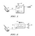
- FIG. 1a simplified and representative system diagram showing a device 101 , e.g., cellular phone or other communication device, with an interface 103 to an auxiliary device 105 will be briefly discussed and described.
- the device 101e.g., cellular phone or other communication device is known other than the modifications and the like discussed and described herein.
- the auxiliary device 105as depicted in FIG. 1 , includes known handsfree functionality and includes means for accessing a power source 106 , e.g., an auxiliary power plug (cigarette lighter plug) as may be found, for example, in an automobile, boat, RV, or the like, or a conventional household AC power outlet.
- a power source 106e.g., an auxiliary power plug (cigarette lighter plug) as may be found, for example, in an automobile, boat, RV, or the like, or a conventional household AC power outlet.
- the stereo systemincludes integrated interface support (interface further described below) and may further include an optional microphone 207 and stereo (right and left) speakers 209 .
- This systemmay be used to support handsfree operation of the device 101 , e.g., cellular phone, or may be used to play stereo music or audio through the stereo system 205 where the music is provided by the device or cellular phone, via for example MP3 player functionality or the like.
- the auxiliary devicemay be integrated with various other functions or apparatus including, for example, a navigation or computing unit or the automobile or the like.
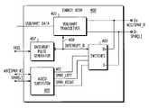
- a conventional communication deviceincludes a processor 307 (it is understood that this may include various other known functionality of communication devices) and in one or more embodiments further includes an interface transceiver 309 .
- the processor and interface transceiverare arranged and constructed to exchange data via data bus 311 .
- the processor 307when suitably equipped can provide speaker audio output at SPKR_L 313 in mono mode or SPKR_L (left audio channel) 313 and SPKR_R (right audio channel) 314 if in stereo mode, where the mono mode may correspond to a conventional phone call and the stereo mode may correspond to playing stereo music via an MP3 player, stereo radio, or the like (incorporated with the communication device).
- Microphone audio 315is an input to the processor 307 . These audio inputs and outputs are coupled to the interface transceiver 309 as shown.
- the interface transceiver 309supports the interface 305 including various modes of operation. These modes of operation are supported via a physical interface comprising at the interface transceiver a 4 wire USB mini-B receptacle and plug 320 with a VBUS, D ⁇ , D+, and GND line as shown.
- the modesinclude a USB mode 321 , a Universal Asynchronous Receiver & Transceiver (UART) mode 323 , a mono mode 325 , and a stereo mode 327 .
- a physical interface at the auxiliary device 303may include a mini-A receptacle and plug 329 or may be hardwired.
- D ⁇carries SPKR_L and D+ carries SPKR_R to the auxiliary device.
- the interface transceiverimposes or inserts an interrupt signal or pulse on SPKR_L when the communication device wants to change the operating mode, e.g., inform the auxiliary device that data is going to be sent and an interrupt pulse is inserted on SPKR_R by the auxiliary device to inform the interface transceiver that data will be sent.
- the auxiliary device 303can take many forms where the exemplary one shown includes power (VBUS 331 ) supplied in a known manner from Regulators 333 that are coupled to a power source such as a 12V automotive battery or other power source as may be appropriate. These regulators also supply power to other functions in the auxiliary device, such as the transceiver amplifier 335 and optional processor 341 .
- the transceiver amplifiersupports the interface 305 in one or more modes of operation and is shown driving speakers 337 and receiving microphone audio from a microphone 339 (e.g., in accordance with a speaker phone or handsfree function or to play a stereo signal).
- the interface transceiver 400 or portion thereofincludes a USB/UART transceiver 401 that is coupled to USB or UART data lines or bus, from, for example, a cellular phone or the like, as well as D+ (MIC or SPKR_R depending on mode) and D ⁇ (SPKR or SPKR_L depending on mode) at an interface, such as, the interface 305 . Further included is a switching function 403 that includes various switches or transmission gates that are used to route, for example audio appropriately, as well as isolate or interrupt various paths as needed.
- the switching function 403is also coupled to D ⁇ and D+ at the interface.
- An audio subsystem 405is coupled via a microphone and SPKR ports to the switching function 403 as well as via microphone or speaker right and speaker or speaker left ports to, the cellular phone, etc.
- a pulse or interrupt pulse generator 407that provides an interrupt or control pulse or signal at 409 . This pulse can be used to control the UART transceiver 401 and the switching function 403 so as to insert, impose, or inject an interrupt pulse in a path (audio path) and concurrently interrupt or disconnect the path for the duration of the pulse, i.e. the path can be reconnected after the pulse.
- a low impedance portion of the pathfrom, for example, a source or audio driver, can be isolated from a second portion while the interrupt pulse is injected using a conventional UART transmitter on the second portion, e.g., the D ⁇ line.
- a conventional UART transmitteron the second portion, e.g., the D ⁇ line.
- an interrupt signalcan be provided in an audio path between a source (audio driver) and a sink (speaker or audio amplifier), where the method includes interrupting the audio path between the source and the sink using the switches or switching function 403 and then injecting an interrupt pulse in the audio path using the UART transceiver 401 .
- the interrupt pulseis inserted while the audio path is interrupted and then reconnecting the audio path via the switching function occurs.
- the interrupting and inserting timing, etc.is controlled by the pulse generator 407 .
- FIG. 5shows a diagram with amplitude 501 on the vertical axis as a function of time 503 on the horizontal axis.
- a signal 505such as an audio signal, is depicted with an interrupt pulse 507 inserted in the signal 505 .
- the interrupt pulsenormally has one or more specifications that may be interface dependent.
- the interrupt pulse 507has a predetermined time or time window 509 that must be greater than 200 nanoseconds (ns) and less than 500 ns as well as a predetermined or specified amplitude that should be greater than 2.9 volts 511 .
- This interrupt pulseis in accordance, for example, with CEA-936 recommendations.
- FIG. 6a more detailed diagram of a system or apparatus suitable for implementation in one or more integrated circuits to provide the interrupt pulse in an audio or other signal path according to FIG. 4 in one or more embodiments will be discussed and described.
- the system of FIG. 6can be implemented as a portion of the UART transceiver 401 , switching function 403 and pulse generator 407 of FIG. 4 .
- FIG. 6depicts an audio driver 601 in exemplary form.
- This driverin various embodiments is a source, e.g. low impedance source, and would typically be part of the communications device 301 or cellular phone.
- the driver 601is coupled to a transmission gate 603 or other (normally) electronic switch that is coupled in turn to a USB connector (D ⁇ or SPKR or SPKR_L depending on operating mode) 605 .
- a transmission gate 603When the transmission gate 603 is enabled, audio or other signals from the source or driver is routed or coupled to a consuming or sink node, e.g., via the interface 305 to the auxiliary device 303 .
- the transmission gateis open or disabled the driver 601 and corresponding portion of the path are isolated from the remainder of the path, i.e. from the transmission gate to the auxiliary device.
- a pulse transmitter 607part of a UART transceiver in one or more embodiments.
- This transceiver 607normally, when enabled in a data mode via an enable signal at 611 as is known and as provided, for example, by the device 307 or communication device, transmits or sends data at 609 from the device or communication device to the USB connector 605 and thus, for example, the auxiliary device.
- the transceiverwhen enabled, receives data from USB connector 613 , thus the auxiliary device, and sends the data to 609 and thus the device or cellular phone.
- a pulse generator 615that is configured such that when triggered by a trig signal 617 from, for example a cellular phone or the like, generates or provides an output pulse or control pulse at 619 .
- this control pulseis a negative pulse and lasts for a time period or predetermined duration, such as 200-500 ns as in FIG. 5 .
- This control pulseis coupled to an AND gate 621 and AND'd with an audio enable signal 623 available from the device or cellular phone, to provide an output signal at 625 . It will be appreciated that the signal at 625 is high if the audio enable signal 623 is high unless the control pulse exists. If the signal at 625 is high the transmission gate is ON or enabled.
- the transmission gateis configured to interrupt a path (e.g., audio path) between a source or communication device, e.g., cellular phone and a sink or interface, e.g., CarKit interface or the like, and thus auxiliary device (Car Kit or the like) responsive to and during the control pulse.
- a pathe.g., audio path
- a source or communication devicee.g., cellular phone and a sink or interface, e.g., CarKit interface or the like
- auxiliary deviceCar Kit or the like
- control pulse at 619is coupled to the UART or pulse transmitter 607 which is responsive to the control pulse and configured to inject or insert an interrupt pulse in the path, signal path, or audio path while the path is interrupted. More specifically the pulse is coupled at an inverting input of an OR gate 727 as well as at an inverting enable input of UART driver or transmitter 629 . Note that the “normal” enable 611 can be OR'd with the control pulse (inverted) with the result used to enable the UART driver or transmitter 629 . This arrangement, while not depicted, would be similar to the arrangement at OR gate 627 .
- UART datais coupled to the other input of the OR gate and thus the output of the OR gate is equal to the UART data until the control pulse is present in which case it is high while or during the control pulse.
- the UART drivertransmits or sends, e.g. injects or inserts an interrupt pulse in the path (audio or other signal path). Note this is concurrent with the transmission gate being open and audio driver or the like thus being isolated from the balance of the path.
- FIG. 6shows a system that includes a pulse generator 615 configured to provide a control pulse at 619 , a switch, e.g., a transmission gate 603 , configured to interrupt a path between a communication device and an auxiliary device via an interface including D ⁇ at 605 during the control pulse and a pulse transmitter 607 that is responsive to the control pulse and configured to inject an interrupt pulse in the path while the path is interrupted.
- the switch or transmission gate 603couples an audio driver 601 to the path when the path between the communication device and the auxiliary device is in an audio mode (audio enable 623 high and the control pulse is not present.
- the transmission gateisolates the audio driver from the path when the control pulse is present.
- the pulse transmitter 607in various embodiments further comprises a universal asynchronous receiver and transmitter 629 (UART) that is enabled and driven by the control pulse to inject an interrupt pulse corresponding to the control pulse in the path when the path is in an audio mode.
- UARTfurther supports data communications between, for example, the communication device and the auxiliary device when the path is in a data mode (e.g., audio enable 623 low and enable 611 high).
- the interrupt pulseis used or injected into the path to signal to the auxiliary device that the path will be switched to a data mode.
- the pulse generator 615 and the pulse transmitter 607are further configured in one or more embodiments to inject a pulse in the path in accordance with a Consumer Electronics Association cellular phone CarKit interface Standard, e.g., CEA-936 standard.
- the system of FIG. 6is suitable for and may be advantageously implemented in integrated circuit form with very few modifications over base requirements for a CarKit interface, since the transmission gate and UART are normally required for the basic interface, at least if any form of data is to be exchanged.
- the control pulse and thus interrupt pulseis arranged to have a predetermined or specified timing characteristic or duration that is dependent on a resistor capacitor circuit and in one or more embodiments this duration or timing characteristic is in accordance with, for example, the CEA-936 standards (see FIG. 5 ).
- the pulse transmitterinsures that the interrupt pulse has a minimum or predetermined, i.e., specified, amplitude (largely dependent on supply voltage to the UART).
- the system or other similarly configured systems or circuitscan implement various methods of providing interrupt signals in, for example, an audio or other signal path between a source and a sink or destination node.
- the methodincludes interrupting the audio path between the source and the sink, injecting an interrupt pulse in the audio path while the audio path is interrupted, and then reconnecting the audio path.
- these methodsinclude generating a control signal wherein the interrupting the audio path and the injecting the interrupt pulse are responsive to the control signal.
- the generating the control signalmay comprise producing a pulse with timing controlled by a resistor capacitor ratio and latching the pulse with a Schmidt trigger to generate the control signal.
- the injecting the interrupt pulsemay advantageously use a UART.
- interrupting the audio pathprovides for or includes isolating a low impedance portion of the audio path and then injecting the interrupt pulse then injecting the interrupt pulse in a second portion of the audio path.
- Thiscan advantageously be utilized for interrupting a path in an audio/UART interface (cell phone to CarKit interface—CEA-936) during an audio mode, thereby allowing for multiplexed control or payload signaling concurrently with audio exchanges.
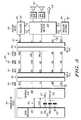
- FIG. 7shows a pulse circuit 701 configured to provide a pulse waveform with a duration dependent on a resistor capacitor circuit and a Schmidt trigger based detector 703 that provides, responsive to the pulse waveform, the control pulse.
- a resistor capacitor pulse circuitis coupled to a Schmidt trigger detector and both are collectively configured to provide the control pulse with a predetermined timing characteristic.
- FIG. 7shows a trig voltage 617 that includes a rising edge 705 . This is coupled to an inverter 707 and an AND gate 709 .
- the inverter 707is coupled via a resistor to the other input of the AND gate 709 which is also a node with a capacitor to ground.
- the resistor capacitor pair 708insures that the AND gate outputs a positive pulse 710 for a time dependent on the resistor capacitor pair, nominally 12 nano seconds (ns) in one embodiment.
- the positive pulse 710turns off a p-channel Field Effect Transistor (FET) 713 and turns on an n-channel FET 711 .
- FETField Effect Transistor
- the resistor string 715has a value of 150 K ohms (the FET adds another 66 K ohms) and the capacitor 717 is 1.62 pico-farads, yielding an RC time constant of 350 ns (midway between the 200-500 ns specification noted in FIG. 5 ).
- the resistor stringis shown as a plurality of resistors (seven), since the pulse generator is intended to be implemented as an integrated circuit and it may be more space efficient to lay out the resistors as many rather than only one or two structures. It is also noted that the p-channel FET 713 is not a low resistance high gain device. Its characteristics versus process and temperature variables tend to help compensate for corresponding variations in the resistor string and capacitor.
- the waveform 718is coupled to and turns off an n-channel FET 719 and turns on a p-channel FET 721 (while the waveform is below a threshold for the n-channel FET 721 ), thus generating a positive pulse 722 .
- the positive pulse 722turns another n-channel FET 723 on thereby pulling the output 619 low and starting the control pulse. This is reinforced by turning on a p-channel FET 725 which tends to turn off another p-channel FET 727 and turn on the n-channel FET 723 .
- the pulse 722When the waveform 718 goes high, the pulse 722 will go low turning n-channel FET 723 off, p-channel FET 727 on, and p-channel FET 725 off, thus completing the Schmidt trigger operation and causing the output at 619 to go high thereby ending the control pulse or signal.
- the output pulseis a negative pulse with a time duration or timing characteristic dependent on the RC circuit including resistor string 715 and capacitor 717 .
- auxiliary device or interface transceiver portion thereofmay be integrated as part of, for example, an automotive stereo unit (see FIG. 2 ) or as will be evident integrated as part of various other functions including, for example, an automobile or the like.
Landscapes
- Engineering & Computer Science (AREA)
- Computer Networks & Wireless Communication (AREA)
- Signal Processing (AREA)
- Telephone Function (AREA)
- Mobile Radio Communication Systems (AREA)
- Fittings On The Vehicle Exterior For Carrying Loads, And Devices For Holding Or Mounting Articles (AREA)
Abstract
Description
Claims (7)
Priority Applications (4)
| Application Number | Priority Date | Filing Date | Title |
|---|---|---|---|
| US11/096,607US8913634B2 (en) | 2005-04-01 | 2005-04-01 | Method and apparatus facilitating multi mode interfaces |
| JP2008504175AJP5294843B2 (en) | 2005-04-01 | 2006-03-24 | Method and apparatus for simplifying a multi-mode interface |
| PCT/US2006/010579WO2006107607A2 (en) | 2005-04-01 | 2006-03-24 | Method and apparatus faciltating multi mode interfaces |
| KR1020077025297AKR101281243B1 (en) | 2005-04-01 | 2006-03-24 | Method and apparatus facilitating multi mode interfaces |
Applications Claiming Priority (1)
| Application Number | Priority Date | Filing Date | Title |
|---|---|---|---|
| US11/096,607US8913634B2 (en) | 2005-04-01 | 2005-04-01 | Method and apparatus facilitating multi mode interfaces |
Publications (2)
| Publication Number | Publication Date |
|---|---|
| US20060222021A1 US20060222021A1 (en) | 2006-10-05 |
| US8913634B2true US8913634B2 (en) | 2014-12-16 |
Family
ID=37070414
Family Applications (1)
| Application Number | Title | Priority Date | Filing Date |
|---|---|---|---|
| US11/096,607Active2032-05-01US8913634B2 (en) | 2005-04-01 | 2005-04-01 | Method and apparatus facilitating multi mode interfaces |
Country Status (4)
| Country | Link |
|---|---|
| US (1) | US8913634B2 (en) |
| JP (1) | JP5294843B2 (en) |
| KR (1) | KR101281243B1 (en) |
| WO (1) | WO2006107607A2 (en) |
Families Citing this family (6)
| Publication number | Priority date | Publication date | Assignee | Title |
|---|---|---|---|---|
| US7899946B2 (en)* | 2008-01-11 | 2011-03-01 | Modu Ltd. | Audio and USB multiplexing |
| US7937109B2 (en)* | 2008-01-24 | 2011-05-03 | Hewlett-Packard Development Company, L.P. | Current source driver for common ground signal interface |
| US9182939B1 (en) | 2008-09-19 | 2015-11-10 | Nvidia Corporation | Method and system for managing the power state of an audio device integrated in a graphics device |
| US8190937B1 (en)* | 2008-09-19 | 2012-05-29 | Nvidia Corporation | Method and system for managing the power state of an audio device integrated in a graphics device |
| US8347118B1 (en) | 2008-09-19 | 2013-01-01 | Nvidia Corporation | Method and system for managing the power state of an audio device integrated in a graphics device |
| CN102201827B (en)* | 2011-06-15 | 2014-02-19 | 天地融科技股份有限公司 | Audio signal receiving and switching device and audio signal transmission system |
Citations (30)
| Publication number | Priority date | Publication date | Assignee | Title |
|---|---|---|---|---|
| US3968333A (en)* | 1973-09-18 | 1976-07-06 | Superior Continental Corporation | Battery charger control circuit for telephone transmission systems |
| US4429997A (en)* | 1978-03-27 | 1984-02-07 | Raytheon Company | Phase-locked loop laser gyroscope system |
| US4979094A (en)* | 1987-04-07 | 1990-12-18 | Possum Controls Limited | Control system |
| US5091725A (en)* | 1989-08-18 | 1992-02-25 | Atlantic Richfield Company | Well logging tool and system having a switched mode power amplifier |
| US5384539A (en)* | 1990-03-30 | 1995-01-24 | Robert Bosch Gmbh | Process for monitoring inductive loads for faults on the control line using sampling techniques |
| US5430408A (en)* | 1993-03-08 | 1995-07-04 | Texas Instruments Incorporated | Transmission gate circuit |
| US5684679A (en)* | 1995-03-31 | 1997-11-04 | Daewoo Electronics Co., Ltd. | Switching mode power supply capable of reducing the response time thereof |
| US5818949A (en)* | 1994-03-17 | 1998-10-06 | Deremer; Dale D. | Microphone with infared on/off switch |
| US5867794A (en)* | 1996-09-20 | 1999-02-02 | Ericsson Inc. | Audio-output for a portable radio telephone utilizing a vehicle's AM/FM radio |
| US5961333A (en)* | 1996-09-05 | 1999-10-05 | Harrison; Robert G. | Educational and training devices and methods |
| US6057555A (en)* | 1993-07-12 | 2000-05-02 | Peregrine Semiconductor Corporation | High-frequency wireless communication system on a single ultrathin silicon on sapphire chip |
| EP1049347A1 (en)* | 1999-04-27 | 2000-11-02 | Robert Bosch Gmbh | A method and device for establishing a connection between a communication system, particularly a mobile phone, and a corresponding kit |
| US20010034246A1 (en)* | 2000-02-04 | 2001-10-25 | Hutchison James A. | Method and circuit for interfacing a modem in a wireless communication device to a subscriber interface module |
| US20020137505A1 (en)* | 2000-02-18 | 2002-09-26 | Eiche Steven A. | Audio detection for hands-free wireless |
| US20020184566A1 (en)* | 2001-06-01 | 2002-12-05 | Michael Catherwood | Register pointer trap |
| US20030045265A1 (en)* | 2001-08-30 | 2003-03-06 | Shih-Sheng Huang | Audio system with automatic mute control triggered by wireless communication of mobile phones |
| US20030065964A1 (en)* | 2001-09-28 | 2003-04-03 | Rupal Parikh | Registering events while clocking multiple domains |
| US6603986B1 (en)* | 1999-02-01 | 2003-08-05 | Sony Corporation | Method and system for controlling cellular telephone accessory functions |
| US20030174779A1 (en) | 2002-02-12 | 2003-09-18 | Shigeru Sugaya | Radio communication system and method, wireless network forming device, radio transmission unit and method, and radio reception unit and method |
| US20030227980A1 (en)* | 2002-06-07 | 2003-12-11 | Anuj Batra | Ultra wideband (UWB) transmitter architecture |
| US20040161064A1 (en) | 2002-11-15 | 2004-08-19 | Brethour Vernon R. | System and method for processing signals in UWB communications |
| US6806742B1 (en)* | 2003-05-23 | 2004-10-19 | Standard Microsystems Corporation | Phase detector for low power applications |
| US6813350B2 (en)* | 1999-12-11 | 2004-11-02 | Zarlink Semiconductor Inc. | Method and apparatus for detecting dual tone alerting signal in telephone systems |
| US20050018785A1 (en) | 1992-03-26 | 2005-01-27 | Mitsuaki Oshima | Communication system |
| US20050068436A1 (en) | 2001-05-29 | 2005-03-31 | Miriam Fraenkel | CMOS imager for cellular applications and methods of using such |
| US20050189969A1 (en)* | 2004-02-27 | 2005-09-01 | Nicholas Ricardo A. | Total harmonic distortion standard |
| US20050268000A1 (en)* | 2004-05-28 | 2005-12-01 | Carlson Mark J | Accessory identifier in an electronic device |
| US20050267672A1 (en)* | 2004-01-20 | 2005-12-01 | Varec, Inc. | Wireless data collection unit for fuel management system |
| US7103381B1 (en)* | 2002-01-22 | 2006-09-05 | Cypress Semiconductor Corp. | Method and/or apparatus for implementing USB and audio signals shared conductors |
| US20100062759A1 (en)* | 2006-11-23 | 2010-03-11 | Nokia Corporation | Method and device for maintaining continuity of radio transmissions |
Family Cites Families (4)
| Publication number | Priority date | Publication date | Assignee | Title |
|---|---|---|---|---|
| JPH0575745A (en)* | 1991-09-17 | 1993-03-26 | Sharp Corp | Data communication multiplexer in telephone |
| JPH10232924A (en)* | 1997-02-19 | 1998-09-02 | Matsushita Electric Ind Co Ltd | Video capture system |
| JPH11282769A (en)* | 1998-03-26 | 1999-10-15 | Sony Corp | Information input/output terminal equipment |
| JP4659175B2 (en)* | 2000-04-25 | 2011-03-30 | 富士通東芝モバイルコミュニケーションズ株式会社 | Mobile communication terminal |
- 2005
- 2005-04-01USUS11/096,607patent/US8913634B2/enactiveActive
- 2006
- 2006-03-24KRKR1020077025297Apatent/KR101281243B1/ennot_activeExpired - Fee Related
- 2006-03-24WOPCT/US2006/010579patent/WO2006107607A2/enactiveApplication Filing
- 2006-03-24JPJP2008504175Apatent/JP5294843B2/ennot_activeExpired - Fee Related
Patent Citations (30)
| Publication number | Priority date | Publication date | Assignee | Title |
|---|---|---|---|---|
| US3968333A (en)* | 1973-09-18 | 1976-07-06 | Superior Continental Corporation | Battery charger control circuit for telephone transmission systems |
| US4429997A (en)* | 1978-03-27 | 1984-02-07 | Raytheon Company | Phase-locked loop laser gyroscope system |
| US4979094A (en)* | 1987-04-07 | 1990-12-18 | Possum Controls Limited | Control system |
| US5091725A (en)* | 1989-08-18 | 1992-02-25 | Atlantic Richfield Company | Well logging tool and system having a switched mode power amplifier |
| US5384539A (en)* | 1990-03-30 | 1995-01-24 | Robert Bosch Gmbh | Process for monitoring inductive loads for faults on the control line using sampling techniques |
| US20050018785A1 (en) | 1992-03-26 | 2005-01-27 | Mitsuaki Oshima | Communication system |
| US5430408A (en)* | 1993-03-08 | 1995-07-04 | Texas Instruments Incorporated | Transmission gate circuit |
| US6057555A (en)* | 1993-07-12 | 2000-05-02 | Peregrine Semiconductor Corporation | High-frequency wireless communication system on a single ultrathin silicon on sapphire chip |
| US5818949A (en)* | 1994-03-17 | 1998-10-06 | Deremer; Dale D. | Microphone with infared on/off switch |
| US5684679A (en)* | 1995-03-31 | 1997-11-04 | Daewoo Electronics Co., Ltd. | Switching mode power supply capable of reducing the response time thereof |
| US5961333A (en)* | 1996-09-05 | 1999-10-05 | Harrison; Robert G. | Educational and training devices and methods |
| US5867794A (en)* | 1996-09-20 | 1999-02-02 | Ericsson Inc. | Audio-output for a portable radio telephone utilizing a vehicle's AM/FM radio |
| US6603986B1 (en)* | 1999-02-01 | 2003-08-05 | Sony Corporation | Method and system for controlling cellular telephone accessory functions |
| EP1049347A1 (en)* | 1999-04-27 | 2000-11-02 | Robert Bosch Gmbh | A method and device for establishing a connection between a communication system, particularly a mobile phone, and a corresponding kit |
| US6813350B2 (en)* | 1999-12-11 | 2004-11-02 | Zarlink Semiconductor Inc. | Method and apparatus for detecting dual tone alerting signal in telephone systems |
| US20010034246A1 (en)* | 2000-02-04 | 2001-10-25 | Hutchison James A. | Method and circuit for interfacing a modem in a wireless communication device to a subscriber interface module |
| US20020137505A1 (en)* | 2000-02-18 | 2002-09-26 | Eiche Steven A. | Audio detection for hands-free wireless |
| US20050068436A1 (en) | 2001-05-29 | 2005-03-31 | Miriam Fraenkel | CMOS imager for cellular applications and methods of using such |
| US20020184566A1 (en)* | 2001-06-01 | 2002-12-05 | Michael Catherwood | Register pointer trap |
| US20030045265A1 (en)* | 2001-08-30 | 2003-03-06 | Shih-Sheng Huang | Audio system with automatic mute control triggered by wireless communication of mobile phones |
| US20030065964A1 (en)* | 2001-09-28 | 2003-04-03 | Rupal Parikh | Registering events while clocking multiple domains |
| US7103381B1 (en)* | 2002-01-22 | 2006-09-05 | Cypress Semiconductor Corp. | Method and/or apparatus for implementing USB and audio signals shared conductors |
| US20030174779A1 (en) | 2002-02-12 | 2003-09-18 | Shigeru Sugaya | Radio communication system and method, wireless network forming device, radio transmission unit and method, and radio reception unit and method |
| US20030227980A1 (en)* | 2002-06-07 | 2003-12-11 | Anuj Batra | Ultra wideband (UWB) transmitter architecture |
| US20040161064A1 (en) | 2002-11-15 | 2004-08-19 | Brethour Vernon R. | System and method for processing signals in UWB communications |
| US6806742B1 (en)* | 2003-05-23 | 2004-10-19 | Standard Microsystems Corporation | Phase detector for low power applications |
| US20050267672A1 (en)* | 2004-01-20 | 2005-12-01 | Varec, Inc. | Wireless data collection unit for fuel management system |
| US20050189969A1 (en)* | 2004-02-27 | 2005-09-01 | Nicholas Ricardo A. | Total harmonic distortion standard |
| US20050268000A1 (en)* | 2004-05-28 | 2005-12-01 | Carlson Mark J | Accessory identifier in an electronic device |
| US20100062759A1 (en)* | 2006-11-23 | 2010-03-11 | Nokia Corporation | Method and device for maintaining continuity of radio transmissions |
Non-Patent Citations (2)
| Title |
|---|
| International Search Report and Written Opinion for correlating PCT Patent Application No. PCT/US06/10579 dated Jun. 4, 2008. |
| Terry Remple, Meagan Hayes and Dave Wilson, Draft DEA-936-A Mini-USB Analog Carkit Interface, Feb. 7, 2005. |
Also Published As
| Publication number | Publication date |
|---|---|
| JP2008538270A (en) | 2008-10-16 |
| JP5294843B2 (en) | 2013-09-18 |
| WO2006107607A2 (en) | 2006-10-12 |
| KR101281243B1 (en) | 2013-07-02 |
| US20060222021A1 (en) | 2006-10-05 |
| KR20080005393A (en) | 2008-01-11 |
| WO2006107607A3 (en) | 2009-04-16 |
Similar Documents
| Publication | Publication Date | Title |
|---|---|---|
| US7103381B1 (en) | Method and/or apparatus for implementing USB and audio signals shared conductors | |
| US6134456A (en) | Integrated mobile-phone handsfree kit combining with vehicular stereo loudspeakers | |
| CN101210829B (en) | In-vehicle electronic apparatus and in-vehicle electronic system | |
| US7679322B1 (en) | Auxiliary power adapter having device controls | |
| US20080032650A1 (en) | Integrated Bluetooth-FM "xrBlue" Adapter | |
| WO2006107607A2 (en) | Method and apparatus faciltating multi mode interfaces | |
| CN105933823B (en) | Backward compatible system and method for providing power and signals to headphones with active noise cancellation using a 4P audio plug | |
| US20050151422A1 (en) | Universal serial bus connector in a vehicle | |
| US20100109749A1 (en) | Signal transmission path selection circuit and method, and electronic device employing the circuit | |
| US10194549B2 (en) | Accessory apparatus, system, and method for supporting hierarchical connection | |
| US20120214549A1 (en) | Land mobile radio and adapter for use with standard mobile phone headset | |
| EP1418791A2 (en) | Improvements in and relating to audio devices | |
| CN105450708B (en) | Vehicle-mounted interaction platform and on-vehicle information processing method based on mobile terminal | |
| CN103123797A (en) | Vehicular audio playing system and vehicular audio playing method | |
| CN105872869A (en) | Method and device for positive and negative insertion of compatible analog headphones | |
| JPH04503898A (en) | Multi-function, single-conductor microphone-controller | |
| US20080161950A1 (en) | Electronic system, electronic apparatus and method of operating audio unit | |
| US20110046954A1 (en) | Portable audio control system and audio control device thereof | |
| US20070026908A1 (en) | Earphone device with separable wireless transmission module | |
| CN210053548U (en) | Audio playing device, sound system and vehicle | |
| CN113206906A (en) | Electronic equipment assembly and digital earphone | |
| JP2011098662A (en) | On-vehicle apparatus and on-vehicle apparatus system | |
| EP1700463B1 (en) | Accessory functions | |
| CN104149689A (en) | Audio output device and automobile | |
| US20130028431A1 (en) | Multifunctional electronic accessory |
Legal Events
| Date | Code | Title | Description |
|---|---|---|---|
| AS | Assignment | Owner name:FREESCALE SEMICONDUCTOR, INC, TEXAS Free format text:ASSIGNMENT OF ASSIGNORS INTEREST;ASSIGNOR:RUFF, ALAN;REEL/FRAME:016456/0572 Effective date:20050401 | |
| AS | Assignment | Owner name:CITIBANK, N.A. AS COLLATERAL AGENT, NEW YORK Free format text:SECURITY AGREEMENT;ASSIGNORS:FREESCALE SEMICONDUCTOR, INC.;FREESCALE ACQUISITION CORPORATION;FREESCALE ACQUISITION HOLDINGS CORP.;AND OTHERS;REEL/FRAME:018855/0129 Effective date:20061201 Owner name:CITIBANK, N.A. AS COLLATERAL AGENT,NEW YORK Free format text:SECURITY AGREEMENT;ASSIGNORS:FREESCALE SEMICONDUCTOR, INC.;FREESCALE ACQUISITION CORPORATION;FREESCALE ACQUISITION HOLDINGS CORP.;AND OTHERS;REEL/FRAME:018855/0129 Effective date:20061201 | |
| AS | Assignment | Owner name:CITIBANK, N.A.,NEW YORK Free format text:SECURITY AGREEMENT;ASSIGNOR:FREESCALE SEMICONDUCTOR, INC.;REEL/FRAME:024085/0001 Effective date:20100219 Owner name:CITIBANK, N.A., NEW YORK Free format text:SECURITY AGREEMENT;ASSIGNOR:FREESCALE SEMICONDUCTOR, INC.;REEL/FRAME:024085/0001 Effective date:20100219 | |
| AS | Assignment | Owner name:CITIBANK, N.A., AS COLLATERAL AGENT,NEW YORK Free format text:SECURITY AGREEMENT;ASSIGNOR:FREESCALE SEMICONDUCTOR, INC.;REEL/FRAME:024397/0001 Effective date:20100413 Owner name:CITIBANK, N.A., AS COLLATERAL AGENT, NEW YORK Free format text:SECURITY AGREEMENT;ASSIGNOR:FREESCALE SEMICONDUCTOR, INC.;REEL/FRAME:024397/0001 Effective date:20100413 | |
| AS | Assignment | Owner name:CITIBANK, N.A., AS NOTES COLLATERAL AGENT, NEW YORK Free format text:SECURITY AGREEMENT;ASSIGNOR:FREESCALE SEMICONDUCTOR, INC.;REEL/FRAME:030633/0424 Effective date:20130521 Owner name:CITIBANK, N.A., AS NOTES COLLATERAL AGENT, NEW YOR Free format text:SECURITY AGREEMENT;ASSIGNOR:FREESCALE SEMICONDUCTOR, INC.;REEL/FRAME:030633/0424 Effective date:20130521 | |
| FEPP | Fee payment procedure | Free format text:PAYOR NUMBER ASSIGNED (ORIGINAL EVENT CODE: ASPN); ENTITY STATUS OF PATENT OWNER: LARGE ENTITY | |
| AS | Assignment | Owner name:CITIBANK, N.A., AS NOTES COLLATERAL AGENT, NEW YORK Free format text:SECURITY AGREEMENT;ASSIGNOR:FREESCALE SEMICONDUCTOR, INC.;REEL/FRAME:031591/0266 Effective date:20131101 Owner name:CITIBANK, N.A., AS NOTES COLLATERAL AGENT, NEW YOR Free format text:SECURITY AGREEMENT;ASSIGNOR:FREESCALE SEMICONDUCTOR, INC.;REEL/FRAME:031591/0266 Effective date:20131101 | |
| STCF | Information on status: patent grant | Free format text:PATENTED CASE | |
| AS | Assignment | Owner name:FREESCALE SEMICONDUCTOR, INC., TEXAS Free format text:PATENT RELEASE;ASSIGNOR:CITIBANK, N.A., AS COLLATERAL AGENT;REEL/FRAME:037356/0143 Effective date:20151207 Owner name:FREESCALE SEMICONDUCTOR, INC., TEXAS Free format text:PATENT RELEASE;ASSIGNOR:CITIBANK, N.A., AS COLLATERAL AGENT;REEL/FRAME:037356/0553 Effective date:20151207 Owner name:FREESCALE SEMICONDUCTOR, INC., TEXAS Free format text:PATENT RELEASE;ASSIGNOR:CITIBANK, N.A., AS COLLATERAL AGENT;REEL/FRAME:037354/0225 Effective date:20151207 | |
| AS | Assignment | Owner name:MORGAN STANLEY SENIOR FUNDING, INC., MARYLAND Free format text:ASSIGNMENT AND ASSUMPTION OF SECURITY INTEREST IN PATENTS;ASSIGNOR:CITIBANK, N.A.;REEL/FRAME:037486/0517 Effective date:20151207 | |
| AS | Assignment | Owner name:MORGAN STANLEY SENIOR FUNDING, INC., MARYLAND Free format text:ASSIGNMENT AND ASSUMPTION OF SECURITY INTEREST IN PATENTS;ASSIGNOR:CITIBANK, N.A.;REEL/FRAME:037518/0292 Effective date:20151207 | |
| AS | Assignment | Owner name:MORGAN STANLEY SENIOR FUNDING, INC., MARYLAND Free format text:SECURITY AGREEMENT SUPPLEMENT;ASSIGNOR:NXP B.V.;REEL/FRAME:038017/0058 Effective date:20160218 | |
| AS | Assignment | Owner name:MORGAN STANLEY SENIOR FUNDING, INC., MARYLAND Free format text:SUPPLEMENT TO THE SECURITY AGREEMENT;ASSIGNOR:FREESCALE SEMICONDUCTOR, INC.;REEL/FRAME:039138/0001 Effective date:20160525 | |
| AS | Assignment | Owner name:MORGAN STANLEY SENIOR FUNDING, INC., MARYLAND Free format text:CORRECTIVE ASSIGNMENT TO CORRECT THE REMOVE APPLICATION 12092129 PREVIOUSLY RECORDED ON REEL 038017 FRAME 0058. ASSIGNOR(S) HEREBY CONFIRMS THE SECURITY AGREEMENT SUPPLEMENT;ASSIGNOR:NXP B.V.;REEL/FRAME:039361/0212 Effective date:20160218 | |
| AS | Assignment | Owner name:NXP, B.V., F/K/A FREESCALE SEMICONDUCTOR, INC., NETHERLANDS Free format text:RELEASE BY SECURED PARTY;ASSIGNOR:MORGAN STANLEY SENIOR FUNDING, INC.;REEL/FRAME:040925/0001 Effective date:20160912 Owner name:NXP, B.V., F/K/A FREESCALE SEMICONDUCTOR, INC., NE Free format text:RELEASE BY SECURED PARTY;ASSIGNOR:MORGAN STANLEY SENIOR FUNDING, INC.;REEL/FRAME:040925/0001 Effective date:20160912 | |
| AS | Assignment | Owner name:NXP B.V., NETHERLANDS Free format text:RELEASE BY SECURED PARTY;ASSIGNOR:MORGAN STANLEY SENIOR FUNDING, INC.;REEL/FRAME:040928/0001 Effective date:20160622 | |
| AS | Assignment | Owner name:NXP USA, INC., TEXAS Free format text:CHANGE OF NAME;ASSIGNOR:FREESCALE SEMICONDUCTOR INC.;REEL/FRAME:040652/0180 Effective date:20161107 | |
| AS | Assignment | Owner name:NXP USA, INC., TEXAS Free format text:CORRECTIVE ASSIGNMENT TO CORRECT THE NATURE OF CONVEYANCE LISTED CHANGE OF NAME SHOULD BE MERGER AND CHANGE PREVIOUSLY RECORDED AT REEL: 040652 FRAME: 0180. ASSIGNOR(S) HEREBY CONFIRMS THE MERGER AND CHANGE OF NAME;ASSIGNOR:FREESCALE SEMICONDUCTOR INC.;REEL/FRAME:041354/0148 Effective date:20161107 | |
| AS | Assignment | Owner name:MORGAN STANLEY SENIOR FUNDING, INC., MARYLAND Free format text:CORRECTIVE ASSIGNMENT TO CORRECT THE REMOVE PATENTS 8108266 AND 8062324 AND REPLACE THEM WITH 6108266 AND 8060324 PREVIOUSLY RECORDED ON REEL 037518 FRAME 0292. ASSIGNOR(S) HEREBY CONFIRMS THE ASSIGNMENT AND ASSUMPTION OF SECURITY INTEREST IN PATENTS;ASSIGNOR:CITIBANK, N.A.;REEL/FRAME:041703/0536 Effective date:20151207 | |
| AS | Assignment | Owner name:MORGAN STANLEY SENIOR FUNDING, INC., MARYLAND Free format text:CORRECTIVE ASSIGNMENT TO CORRECT THE REMOVE APPLICATION 12681366 PREVIOUSLY RECORDED ON REEL 039361 FRAME 0212. ASSIGNOR(S) HEREBY CONFIRMS THE SECURITY AGREEMENT SUPPLEMENT;ASSIGNOR:NXP B.V.;REEL/FRAME:042762/0145 Effective date:20160218 Owner name:MORGAN STANLEY SENIOR FUNDING, INC., MARYLAND Free format text:CORRECTIVE ASSIGNMENT TO CORRECT THE REMOVE APPLICATION 12681366 PREVIOUSLY RECORDED ON REEL 038017 FRAME 0058. ASSIGNOR(S) HEREBY CONFIRMS THE SECURITY AGREEMENT SUPPLEMENT;ASSIGNOR:NXP B.V.;REEL/FRAME:042985/0001 Effective date:20160218 | |
| MAFP | Maintenance fee payment | Free format text:PAYMENT OF MAINTENANCE FEE, 4TH YEAR, LARGE ENTITY (ORIGINAL EVENT CODE: M1551) Year of fee payment:4 | |
| AS | Assignment | Owner name:SHENZHEN XINGUODU TECHNOLOGY CO., LTD., CHINA Free format text:CORRECTIVE ASSIGNMENT TO CORRECT THE TO CORRECT THE APPLICATION NO. FROM 13,883,290 TO 13,833,290 PREVIOUSLY RECORDED ON REEL 041703 FRAME 0536. ASSIGNOR(S) HEREBY CONFIRMS THE THE ASSIGNMENT AND ASSUMPTION OF SECURITYINTEREST IN PATENTS.;ASSIGNOR:MORGAN STANLEY SENIOR FUNDING, INC.;REEL/FRAME:048734/0001 Effective date:20190217 | |
| AS | Assignment | Owner name:NXP B.V., NETHERLANDS Free format text:RELEASE BY SECURED PARTY;ASSIGNOR:MORGAN STANLEY SENIOR FUNDING, INC.;REEL/FRAME:050745/0001 Effective date:20190903 Owner name:NXP B.V., NETHERLANDS Free format text:RELEASE BY SECURED PARTY;ASSIGNOR:MORGAN STANLEY SENIOR FUNDING, INC.;REEL/FRAME:050744/0097 Effective date:20190903 | |
| AS | Assignment | Owner name:MORGAN STANLEY SENIOR FUNDING, INC., MARYLAND Free format text:CORRECTIVE ASSIGNMENT TO CORRECT THE REMOVE APPLICATION 12298143 PREVIOUSLY RECORDED ON REEL 042985 FRAME 0001. ASSIGNOR(S) HEREBY CONFIRMS THE SECURITY AGREEMENT SUPPLEMENT;ASSIGNOR:NXP B.V.;REEL/FRAME:051029/0001 Effective date:20160218 Owner name:MORGAN STANLEY SENIOR FUNDING, INC., MARYLAND Free format text:CORRECTIVE ASSIGNMENT TO CORRECT THE REMOVE APPLICATION 12298143 PREVIOUSLY RECORDED ON REEL 042762 FRAME 0145. ASSIGNOR(S) HEREBY CONFIRMS THE SECURITY AGREEMENT SUPPLEMENT;ASSIGNOR:NXP B.V.;REEL/FRAME:051145/0184 Effective date:20160218 Owner name:MORGAN STANLEY SENIOR FUNDING, INC., MARYLAND Free format text:CORRECTIVE ASSIGNMENT TO CORRECT THE REMOVE APPLICATION 12298143 PREVIOUSLY RECORDED ON REEL 039361 FRAME 0212. ASSIGNOR(S) HEREBY CONFIRMS THE SECURITY AGREEMENT SUPPLEMENT;ASSIGNOR:NXP B.V.;REEL/FRAME:051029/0387 Effective date:20160218 Owner name:MORGAN STANLEY SENIOR FUNDING, INC., MARYLAND Free format text:CORRECTIVE ASSIGNMENT TO CORRECT THE REMOVE APPLICATION12298143 PREVIOUSLY RECORDED ON REEL 039361 FRAME 0212. ASSIGNOR(S) HEREBY CONFIRMS THE SECURITY AGREEMENT SUPPLEMENT;ASSIGNOR:NXP B.V.;REEL/FRAME:051029/0387 Effective date:20160218 Owner name:MORGAN STANLEY SENIOR FUNDING, INC., MARYLAND Free format text:CORRECTIVE ASSIGNMENT TO CORRECT THE REMOVE APPLICATION12298143 PREVIOUSLY RECORDED ON REEL 042985 FRAME 0001. ASSIGNOR(S) HEREBY CONFIRMS THE SECURITY AGREEMENT SUPPLEMENT;ASSIGNOR:NXP B.V.;REEL/FRAME:051029/0001 Effective date:20160218 Owner name:MORGAN STANLEY SENIOR FUNDING, INC., MARYLAND Free format text:CORRECTIVE ASSIGNMENT TO CORRECT THE REMOVE APPLICATION 12298143 PREVIOUSLY RECORDED ON REEL 038017 FRAME 0058. ASSIGNOR(S) HEREBY CONFIRMS THE SECURITY AGREEMENT SUPPLEMENT;ASSIGNOR:NXP B.V.;REEL/FRAME:051030/0001 Effective date:20160218 Owner name:MORGAN STANLEY SENIOR FUNDING, INC., MARYLAND Free format text:CORRECTIVE ASSIGNMENT TO CORRECT THE REMOVE APPLICATION12298143 PREVIOUSLY RECORDED ON REEL 042762 FRAME 0145. ASSIGNOR(S) HEREBY CONFIRMS THE SECURITY AGREEMENT SUPPLEMENT;ASSIGNOR:NXP B.V.;REEL/FRAME:051145/0184 Effective date:20160218 | |
| AS | Assignment | Owner name:MORGAN STANLEY SENIOR FUNDING, INC., MARYLAND Free format text:CORRECTIVE ASSIGNMENT TO CORRECT THE REMOVE APPLICATION11759915 AND REPLACE IT WITH APPLICATION 11759935 PREVIOUSLY RECORDED ON REEL 037486 FRAME 0517. ASSIGNOR(S) HEREBY CONFIRMS THE ASSIGNMENT AND ASSUMPTION OF SECURITYINTEREST IN PATENTS;ASSIGNOR:CITIBANK, N.A.;REEL/FRAME:053547/0421 Effective date:20151207 | |
| AS | Assignment | Owner name:NXP B.V., NETHERLANDS Free format text:CORRECTIVE ASSIGNMENT TO CORRECT THE REMOVEAPPLICATION 11759915 AND REPLACE IT WITH APPLICATION11759935 PREVIOUSLY RECORDED ON REEL 040928 FRAME 0001. ASSIGNOR(S) HEREBY CONFIRMS THE RELEASE OF SECURITYINTEREST;ASSIGNOR:MORGAN STANLEY SENIOR FUNDING, INC.;REEL/FRAME:052915/0001 Effective date:20160622 | |
| AS | Assignment | Owner name:NXP, B.V. F/K/A FREESCALE SEMICONDUCTOR, INC., NETHERLANDS Free format text:CORRECTIVE ASSIGNMENT TO CORRECT THE REMOVEAPPLICATION 11759915 AND REPLACE IT WITH APPLICATION11759935 PREVIOUSLY RECORDED ON REEL 040925 FRAME 0001. ASSIGNOR(S) HEREBY CONFIRMS THE RELEASE OF SECURITYINTEREST;ASSIGNOR:MORGAN STANLEY SENIOR FUNDING, INC.;REEL/FRAME:052917/0001 Effective date:20160912 | |
| MAFP | Maintenance fee payment | Free format text:PAYMENT OF MAINTENANCE FEE, 8TH YEAR, LARGE ENTITY (ORIGINAL EVENT CODE: M1552); ENTITY STATUS OF PATENT OWNER: LARGE ENTITY Year of fee payment:8 |