US8913003B2 - Free-space multi-dimensional absolute pointer using a projection marker system - Google Patents
Free-space multi-dimensional absolute pointer using a projection marker systemDownload PDFInfo
- Publication number
- US8913003B2 US8913003B2US11/777,073US77707307AUS8913003B2US 8913003 B2US8913003 B2US 8913003B2US 77707307 AUS77707307 AUS 77707307AUS 8913003 B2US8913003 B2US 8913003B2
- Authority
- US
- United States
- Prior art keywords
- handheld device
- spots
- optical
- cursor
- image
- Prior art date
- Legal status (The legal status is an assumption and is not a legal conclusion. Google has not performed a legal analysis and makes no representation as to the accuracy of the status listed.)
- Expired - Fee Related, expires
Links
Images


Classifications
- G—PHYSICS
- G06—COMPUTING OR CALCULATING; COUNTING
- G06F—ELECTRIC DIGITAL DATA PROCESSING
- G06F3/00—Input arrangements for transferring data to be processed into a form capable of being handled by the computer; Output arrangements for transferring data from processing unit to output unit, e.g. interface arrangements
- G06F3/01—Input arrangements or combined input and output arrangements for interaction between user and computer
- G06F3/03—Arrangements for converting the position or the displacement of a member into a coded form
- G06F3/041—Digitisers, e.g. for touch screens or touch pads, characterised by the transducing means
- G06F3/042—Digitisers, e.g. for touch screens or touch pads, characterised by the transducing means by opto-electronic means
- G06F3/0421—Digitisers, e.g. for touch screens or touch pads, characterised by the transducing means by opto-electronic means by interrupting or reflecting a light beam, e.g. optical touch-screen
Definitions
- the present inventionrelates generally to a data processing system. More particularly, this invention relates to free-space multi-dimensional absolute pointer using a projection marker system.
- a presentation systemincludes, but is not limited to, a projection-based marker apparatus to project one or more optical spots on a display surface for displaying machine generated content capable of being manipulated via a cursor of a pointing device, a handheld device to wirelessly capture the projected optical spots from the display surface, and a control unit communicatively coupled to the projection-based marker apparatus and the handheld device to determine coordinates of the cursor based on characteristics of the captured light spots.
- FIG. 1is a block diagram illustrating major components of a system which may be used with one embodiment of the invention.
- FIGS. 2A and 2Bare diagrams illustrating certain light spots according to certain embodiments of the invention.
- FIGS. 3A-3Care diagrams illustrating certain configurations of major components of a system according to one embodiment of the invention.
- FIGS. 4A-4Care block diagrams illustrating an operating environment according to one embodiment of the invention.
- FIG. 5is a block diagram illustrating a presentation system according to one embodiment.
- FIG. 6is a block diagram illustrating a presentation system according to an alternative embodiment.
- FIGS. 7A and 7Bare block diagrams illustrating a presentation system according to certain alternative embodiments.
- FIG. 8is a block diagram illustrating a data processing system which may be used with one embodiment of the invention.
- a free-space absolute pointerprovides such a tool by combining simple 3D pointing with a graphical user interface on a large screen monitor/TV.
- the WavItis an absolute pointer, where a user points is where the cursor goes. It works on any type of screen (e.g., CRT, DLP, RPTV, LCD, Plasma etc).
- the WavItalso tracks other degrees of freedom, such as the absolute angle of rotation of the user's wrist, and the user's absolute distance away from the screen. Some versions also track the user's location in the room. All this takes place in real time, and multiple users can use devices at the same time, which is of particular interest for multi-player gaming.
- An embodiment of the inventionis to expand on ways in which the WavIt absolute pointing system may be engineered to work with large front- (and/or rear-) projection screens.
- the techniques described throughout this applicationfocus on how a projection-POD (Photonic Origin Designator) or p-POD may be developed to allow easy usability and setup, primarily for conference room settings.
- a projection-PODPhotonic Origin Designator
- p-PODmay be developed to allow easy usability and setup, primarily for conference room settings.
- the WavIt multi-dimensional pointeris a high precision tracking system in which the core miniature sensing unit resides inside a handheld remote control device.
- the devicetracks multiple degrees of freedom in absolute space, meaning that not only does it sense where the user is pointing, but it also senses whether the user is twisting his wrist, leaning forward, or sitting to the side of the room.
- Functionally, itbasically acts like a localized GPS (global positioning system) device to track where you are with respect to the TV screen as well a laser-pointer to detect where you are pointing, and a tilt sensor to know how much your wrist is twisted.
- FIG. 1is a block diagram illustrating an exemplary system configuration according to one embodiment of the invention.
- system 100includes a handheld device 101 , a display surface 102 , one or more emitters 103 - 104 , and a data processing system 105 .
- the handheld device 101hereafter referred to as the Handset, may be used by an end user as a pointing device.
- This deviceincorporates an optical sensing unit (such as a CMOS camera) that tracks the Optical Beacons transmitted from a photonic origin designator (POD) 106 (having emitters 103 - 104 ) and calculates its own multi-dimensional coordinates.
- the Handset 101then sends various data (including coordinates) to the POD 106 using one of several wireless technologies.
- the handsetcan also receive RF commands from the POD 106 .
- a receiving device 106receives the data from the Handset using a variety of wireless communication protocols, such as, for example IR, Bluetooth, or IEEE 802.xx protocols.
- This deviceis coupled to a computer via a communication link such as a USB connection.
- the receiverchannels the data from the Handset into a data processing system 105 .
- the receiveralso has the ability to “blast” IR signals to all other Infrared sensitive devices within a predetermined proximity such as a room.
- a sub-section of the PODis dedicated to generating the Optical Beacons, which serve as the optical markers that are tracked by the handset.
- a host computer 105receives the data from the POD. This is handled by a driver, which communicates with the Handset using the USB device. A driver will, based on the data sent, calculate position and pointing coordinates and read the button presses and use this information to control the PC and specific programs or environments.
- a display surfacesuch as a TV screen. This is the screen on which the content, e.g., movies or internet pages, will be displayed. It is also where additional graphical overlays may appear as dictated by a specific user interface.
- the WavIt multidimensional trackeris based on optical tracking of one or more spots, or marker images on an optical sensor.
- an optical sensoris incorporated into a handset. This arrangement is one of the key aspects of WavIt system from which many of its highly desirable features are derived.
- the sensorcan be made to only see or detect a light of a specific wavelength range, such as, for example, ranging approximately from 900 to 1000 nm.
- one or more IR LEDsmay be incorporated into a POD unit that is placed near the screen, with the IR LEDs emitting into the room, towards the handset.
- a POD and/or beaconsmay be incorporated with one or more IR LEDs that emit into the room.
- the beaconsmay be built into the RF receiver and/or USB chip enclosure.
- the RF receivermay only contain the beacons, and RF reception is handled separately by a separate USB dongle unit with RF receiver.
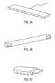
- FIGS. 3A-3Cillustrate certain configurations of devices according to certain embodiments. Other configurations may exist.
- these light sourcesmay be seen or detected by the handset as distinct spots.
- a single spot, as seen by the handset's image sensor and microcontroller,is shown in FIG. 2A according to one embodiment.
- the imageis approximately 13 ⁇ 14 pixels in size.
- spotsmay also be implemented.
- a set of, say, two spotsare processed in the handset unit for their pixel coordinates on the sensor and their signal strengths. This information is subsequently sent to the POD receiver which in turn transmits this data to a computer.
- the coordinatesare sent by a Zigbee RF 2.4 GHz wireless chip.
- the array sizeis approximately 352 ⁇ 288; however, fractional coordinates exist (e.g., a spot can have a location of 251.23, 122.57).
- the resolutionis such that it can effectively have approximately 35200 by 28800 pixels. Other camera resolutions can of course be employed.
- FIGS. 3B and 3COne option is to have a 3-piece system, as shown in FIGS. 3B and 3C , in which the Handset, the RF receiver/USB dongle, and beacons are separate devices.
- the beaconcan now be more portable and adaptable to mounting, such as the spring-loaded battery powered version shown in FIG. 3B .
- the portable beaconscould also have an RF sensor to listen for RF communication and shut down to conserve power if no RF signals are sensed.
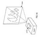
- FIGS. 4A-4Care block diagrams illustrating an operating environment according to one embodiment of the invention.
- FIG. 4Aillustrates a standard projection (front or rear) system.
- FIG. 4Billustrates the same system as detected by the sensor in the handset. Because of the optical filtering in the handset, which blocks substantially all visible light, the screen is essentially blank.
- FIG. 4Cillustrates the system when the IR sources (e.g., lasers) in the projection apparatus are turned on. In this embodiment, two spots, generated by the projected light scattered by the display screen, are detected by the handset's sensor but are invisible to the human eye.
- the IR sourcese.g., lasers
- FIGS. 4A-4Cshow a configuration where all elements of the POD (the RF receiver, the beacons, and the USB PC communication) are co-located in a single unit placed on top of the projector, and where the POD projects the two IR spots onto a screen, for example, into the middle of the screen used by the front (or rear) projector.
- the projection beaconsoriginate from inside the projector (e.g., they are built into the projector system).
- the two spotsare generated by two collimated 980 nm IR lasers, pointing out of the projection-POD at a slightly diverging angle. It should be noted that it is also possible to project light from IR LEDs onto the screen, according to another embodiment, but that care must then be taken to refocus (re-image) the spots whenever the projection-POD is moved so that its distance from the screen changes appreciably. In order to have minimal system dependence (e.g., signal strength and spot size) on the POD location, it is useful to use collimated light sources, and for this reason, lasers are an ideal source.
- the IR spotscould originate from individual sources or from a single source that is optically split into multiple beams.
- the handsetwill now see two spots when pointing in the vicinity of the screen, in a similar way as if a POD had been mounted in the middle of the projection screen.
- the projection-PODhas the benefit of not requiring cables extending from the screen to the PC.
- the setup procedureis also relatively simple—simply point the p-POD at the screen.
- one or more guiding visible lasersare used to facilitate placement of the invisible IR spots onto the screen.
- a wireless radio devicee.g., Chipcon/TI, CC2420 2.4 GHz radio IC
- a micro-controllere.g., Maxim, MaxQ2000
- a computer interface devicee.g., Silicon Labs, CP2102 USB-UART IC
- the Chipcon/TI CC2430combines the wireless radio and micro-controller functions.
- other standard componentssuch as power supply and management circuitry (batteries or voltage regulators), switching and control devices (e.g., mechanical switches), and indicators such as LEDs showing on/off state.
- power supply and management circuitrybatteries or voltage regulators
- switching and control devicese.g., mechanical switches
- indicatorssuch as LEDs showing on/off state.
- a particular configurationwould use the USB computer interface to supply the electrical power for the p-POD, although separate power supplies or batteries may be desirable in some situations (e.g., if the current capacity of the USB interface is exceeded or if remote operation is required).
- An example of the latter casewould be where the lasers are housed separately from the remaining components in the p-POD and the projector is physically separated from the computer. In this case, it may be desirable to power the laser portion using batteries.
- the lasersare mounted such that their emitted beams exit the p-POD at an angle with respect to each other.
- the specific angle between the beamsis not critical, but the optimal range of angles is determined by the range of distances between the POD/projector and the screen and the desired spot separation on the screen. If the separation is too small, then the accuracy in the distance and rotation sensing of the system is reduced, and if the separation is too large, then the angular pointing range of the Handset is reduced since both spots must be within the vision system's field of view.
- a projected spot separation of approximately 15 to 25 cmis a relatively good compromise for a vision system with a 50 degree field of view.
- the p-PODis placed approximately 2 to 3 meters from the screen, where a typical front projector would be located, then the optimal angle between the IR beams would be approximately 3 to 7 degrees. For other operating conditions and system characteristics, different optimal beam angles will result. In some configurations, this angle is fixed, and in other configurations, the angle is made to be adjustable.
- FIG. 6shows an alternative embodiment in which a single IR laser is used to generate the two beams, and a visible alignment laser is incorporated to aid in the placement of the p-POD.
- Lasers that may be used for this purposeare those used in commercially available laser pointers (e.g., red diode lasers). These are typically low power ( ⁇ 5 mW) and inexpensive devices ( ⁇ $1).
- the alignment laserwould be turned on during initial set up of the p-POD and pointing system, and the guide laser would be pointed at, or near, the middle of the screen.
- the visible guide laser beambisects the two IR beams so that when it is pointed at the middle of the screen, it is known that the invisible IR spots are symmetrically located around the middle of the screen.
- the visible guide lasermay be turned off and used only when the p-POD alignment needs to be verified.
- the guide lasermay be controlled by the micro-controller or by other means, such as an electromechanical switch.
- the two IR beamsare generated from a single laser device using optical beamsplitters and mirrors, both standard optical components.
- the beamsplitterdivides the incident IR light from the IR laser into two equal power components and transmits one and reflects the other.
- the reflected beamthen reflects off of the mirror and exits the POD.
- the beamsplitter and mirrorare adjusted to provide the desired beam angle.
- the visible alignment lasermay be included in either the single or two-laser embodiments, and that some or all of the receiver/transmitter components may be housed separately from the lasers.
- the optical components of the p-PODare contained in an enclosure that resides near the projector and the receiver components are contained in a small enclosure that plugs into a computer input port (e.g., a USB dongle device).
- the Handset and receivercommunicate with each other, and the p-POD is used only to project the reference markers onto the screen.
- the p-PODwould then have its own power source and switch. If it is desirable to communicate and control the lasers in the p-POD remotely, then a micro-controller and wireless chip could be included with the p-POD. This arrangement might be desirable in situations where the projector and computer are located far from each other.
- the laser beam vectorsare slightly diverging (as shown in FIGS. 5 and 6 ) and the lasers are co-located with the projector.
- the spot separationwill scale in proportion with the image size.
- the spot separationcan be used to directly calibrate the handset to the screen and no additional pointing and screen calibration, as described in the co-pending applications referenced above, will be required during setup. This is because the ratio of the marker separation and screen size is always the same.
- the lasersmay be mounted such that the divergence between the beams is in the vertical plane instead of the horizontal plane, thus producing spots that are arranged vertically on the screen, or any combination of horizontal and vertical displacement between the beams (e.g., spots arranged diagonally on the screen) is also possible.
- Other geometriesinclude ones in which the beams from the two lasers cross and then diverge before reaching the screen or simply converge from the p-POD and do not cross before hitting the screen.
- the infrared spots that are projected onto a normal screenwill tend to scatter in the same way that the visible light does. This means that for normal screens there will be near Lambertian scatter of the incident light from the p-POD, which will mean that the spots will be visible from very large angles to the screen.
- many projection screens(rear projection in particular) are designed to have asymmetric scattering of the incident light in order to increase the viewing angle, typically in the horizontal plane. Such screens will also work well with the p-POD system since, in general, similar non-uniform scattering will increase the operational region (both in angle and distance from the screen) for the WavIt system.
- projected spotsare relatively easily tailored without the same physical constraints that govern the design of a regular emissive POD.
- the projected spotscan be made bigger without impacting the size of the p-POD.
- Shaped spotssuch as lines and crosses can be projected into various corners of the screen. Larger and shaped spots may be more easily resolved by the detection system in the Handset and thus provide additional information. Multiple spots could be arranged in a circle. The benefit of this is, for example, that if the spots are arranged into a large circle, then the aspect ratio of the circle, which is more accurately determined, could help the WavIt Handset determine its location in the room. For example, a tall oval shape would indicate that the user is positioned to the left or right of the screen and not directly in front. A flat oval would indicate that he is positioned above or below the screen.
- spotscan be used to break the symmetry to allow for discerning whether the user is to the right or left of the screen.
- a four-marker arrangementin which the separation between the markers on the screen is a non-negligible fraction of the user's distance from the screen can permit the distinction between left and right view angle. This can be done using one or more of at least two properties of the markers—their apparent separation (the spot separation on the Handset sensor) and their detected powers. In essence, the pair of markers that are closer to the Handset will both have a larger separation and stronger signal strengths. The side of the screen on which the user is located will determine which pair of spot images is stronger and/or farther apart.
- the WavIt handsetcan be modified to have a very narrowband laser-line band-pass 980 nm filter. This allows light only of very close spectral proximity to 980 nm to pass through to the image sensor.
- a continuous-wave (CW) 980 nm laserusually has a bandwidth of much less than 1 nm, in comparison to an LED, whose spectrum normally spans >10 nm. This means that the system can be made much more optically robust to spurious light sources, such as room lights, essentially increasing the inherent signal to noise ratio of the system.
- the p-POD WavIt systemis compatible with the regular WavIt POD system in that no modifications need be made to the WavIt Handset.
- WavIt tracking systemall the regular benefits of WavIt tracking system apply. For example, it allows for non-interfering robust multi-user operation, and the handset remains relatively low cost, low power, and robust with a very small form factor.
- FIGS. 7A and 7Bshow a rear projection pointing system using a p-POD according to certain embodiments.
- the side viewis shown in FIG. 7A and the top view is shown in FIG. 7B .
- FIGS. 7A and 7Billustrate the use of the p-POD in a conventional folded geometry, a standard arrangement for rear projection systems.
- mirrorsmay be used to direct the expanding cone of light from the projector onto the back of the viewing screen as shown in FIG. 7A . Light incident on the screen is scattered in the general direction of the viewer. This is the basic operational principle for many large screen rear projection televisions (RPTVs).
- RPTVsrear projection televisions
- the screenIn traditional RP systems, the screen is designed to scatter the light isotropically. More recently, systems are designed so that the front surface of the viewing screen scatters the incident light asymmetrically in the horizontal and vertical directions. This is done in order to make more efficient use of the available light since typical viewers will not be located at large vertical angles with respect to the screen. Advanced technologies such as Fresnel lenses and lenticular arrays are used to produce asymmetrically scattering screens.
- FIGS. 7A and 7Bare essentially the equivalent of that shown in FIGS. 5 and 6 for a front projection system.
- the p-PODis mounted adjacent to the projector or projection unit and the projected IR marker spots are positioned near the middle of the screen.
- the IR lightwill be scattered asymmetrically in a manner similar to the visible light, as indicated in FIGS. 7A and 7B .
- the vision system in the Handset held by the viewerwill see two spots located near the center of the screen and displaced horizontally with respect to each other, as shown in FIG. 7B .
- the view angle for the system(wide in the horizontal plane and narrower in the vertical plane) will be similar to that for a normal viewer.
- Other positions for the p-PODare possible.
- the p-PODcould be mounted just below mirror 2 and pointed directly at the back of the screen at a slight angle such that the IR spots hit near the screen center. This arrangement would reduce any losses incurred upon reflections from the mirrors and obviate the need for mirrors with high reflectivity in the IR.
- the p-PODcould be placed behind one of the mirrors with the beams directed at the screen center.
- the mirror behind which the POD is placedwould have to be transparent to the IR.
- Other arrangements that produce the desired spot patternmay also be possible. Note that the folding mirrors are not shown in FIG. 7B , but the essence of the arrangement regarding the placement of the p-POD and the IR spots is not affected. Other configurations may exist.
- laser-based projection TVsare another, recently-developed, type of display system in which the p-POD may be integrated.
- the main difference between standard RP and laser-based RP displaysis the type of light source. Instead of filtered lamp light or, in some cases, visible LEDs, laser-based displays use lasers as the source of illumination.
- the main advantages of laser-based displaysare higher efficiency, smaller size and weight, longer lifetime, and superior color gamut compared with conventional projection systems.
- laser-based TVs and displaysare anticipated to become more prevalent over the next several years due to the continuing improvements in the quality and cost of the component solid state lasers used as the sources.
- Laser-based projection displaysare potentially ideally suited for incorporation of a laser-based p-POD as the source of the reference markers for use with a WavIt pointing device.
- at least one of the three component visible light sourcesred, green, and blue
- the blue lightis obtained by frequency doubling of a near-IR laser, although in some cases, the green and/or the red are also derived from an IR source via second-harmonic generation. This is done because of the difficulty and inefficiency in generating shorter wavelength (e.g. blue) laser light directly.
- a typical wavelength range for the blue componentis 430 nm-490 nm, which places the fundamental wavelength in the 860 nm-980 nm range.
- This lightis typically not used and must be blocked or filtered out of the projection system.
- this rangeis nearly ideal as a near-IR source of marker light.
- the only additional components necessary to use the IR lightmay be collimating, beam steering, and beam splitting optics to separate the IR from the visible light, split it into the desired number of beams (one for each marker), shape the beams as needed, and direct them to the screen.
- IR lasersare generally preferred primarily because of their superior optical properties.
- their inherent brightness (or radiance)is typically many orders of magnitude larger than for incoherent light sources such as LEDs and lamps. This fact results in the ability to more efficiently collect the emitted light from the source and project to a target (e.g., a wall or screen).
- a targete.g., a wall or screen.
- IREDsincoherent light sources
- an IRED-based p-PODBecause of the inherently larger radiance associated with lasers, it is not practical for an IRED-based p-POD to produce the same signal level in a WavIt Handset as a laser-based p-POD with the same optical power. However, it is conceivable, depending on the details of the system, to design a p-POD based on IREDs or other incoherent light sources. The relevant system details include the image detection method in the Handset, the required optical power and beam size, and the distance between the p-POD and the screen.
- the radiance of an optical sourcecannot be increased during transmission through an optical system, and because the inherent radiance of LEDs is much smaller than that of lasers, it is generally difficult to achieve the same amount of detectable optical power scattered off of the screen using LEDs versus using lasers with the same source power. There are a few approaches, however, that may permit the use of LED-based p-PODs in some situations. Note that one of the relevant parameters for determining the signal level is the amount of light from the source that is scattered in the direction of the Handset and not necessarily the radiance of the source. Therefore, even though the radiance of LEDs is much smaller than that of lasers, it is still conceivable that they can be used in some situations.
- the radiancee.g., W/cm 2 -Sr
- the irradiancee.g., W/cm 2
- the required spot sizewill depend on several factors including the detection method, the sensor resolution, and the operating distance.
- the irradiance at the screenmay be increased in one of two ways. Increasing the size of the projection optics (e.g., refractive and/or reflective elements) will decrease the target spot size, thereby increasing the irradiance. However, in many cases, the required optic size would be impractically large. It is also possible to attempt to collimate or focus the light from the LED (or other incoherent light source) to obtain a smaller spot.
- the projection opticse.g., refractive and/or reflective elements
- the required optical systemwould also be impractically large (in length and height).
- the other optionis to simply increase the power projected to the target area by adding additional sources and directing their projected beams to the desired location.
- this approachalso requires a larger effective size for the p-POD and the addition of more sources which results in higher power requirements and additional cost.
- a specific example of an LED-based p-PODuses, for each marker, three separate LEDs, each of which has a narrow divergence angle ( ⁇ 10° is typically achievable for a 5 mm diameter device).
- the LEDsmay be oriented so that their beams have maximum overlap at the target location which may be 1-3 meters away depending on the details of the display system (e.g., front vs rear projection). Additional optics may be added to the system to further reduce the spot size (subject to the inherent radiance limits of the source). In general, the further the p-POD is from the screen, the larger the optics must be to maintain the same irradiance.
- Using a set of three standard high-power (e.g., 35 mW) IREDs for each markerwould result in a ⁇ 100 mW of total power contained in a spot size of ⁇ 10 cm for a screen ⁇ 1 meter away.
- the corresponding irradiance of ⁇ 1.3 mW/cm 2is to be compared with ⁇ 7.5 mW/cm 2 for a 35 mw laser spot of ⁇ 2.5 cm diameter.
- the larger the acceptable spot size for the markerthe more feasible the LED-based p-POD approach becomes since more of the available power is used.
- the maximum acceptable spot sizewill depend on factors such as the detection method and the acceptable separation between the two projected markers.
- the signal on the image sensoris saturated such that the detected image size is much larger than the actual image size.
- broadening the marker size on the screencan be done without significantly affecting the quality of the detected signal.
- the signalmay be improved (larger and/or more stable) by increasing the spot size whether using a laser or LED.
- the upper limit on spot sizeis ultimately determined by the maximum operating distance of the Handset since the images on the sensor approach each other as the user moves farther away from the screen. If the spots are too large then they will become too close to each other on the sensor to resolve for sufficiently large operating distances.
- FIG. 8is a block diagram of a digital processing system, which may be used with one embodiment of the invention.
- the system 800 shown in FIG. 8may be used as a computer system described above, such as, for example, a host computer, a projector, a POD, and/or a handheld device, etc.
- FIG. 8illustrates various components of a computer system, it is not intended to represent any particular architecture or manner of interconnecting the components, as such details are not germane to the present invention. It will also be appreciated that network computers, handheld computers, cell phones, set-top boxes, digital TVs, and other data processing systems which have fewer components or perhaps more components may also be used with the present invention.
- the computer system of FIG. 8may, for example, be an Apple Macintosh computer or an IBM compatible PC.
- the computer system 800which is a form of a data processing system, includes a bus 802 which is coupled to a microprocessor 803 and a ROM 807 , a volatile RAM 805 , and a non-volatile memory 806 .
- the microprocessor 803which may be, for example, a PowerPC G4 or PowerPC G5 microprocessor from Motorola, Inc. or IBM, is coupled to cache memory 804 as shown in the example of FIG. 8 .
- Microprocessor 803may include multiple processors or multiple core logics (e.g., logical processors).
- the bus 802interconnects these various components together and also interconnects these components 803 , 807 , 805 , and 806 to a display controller and display device 808 , as well as to input/output (I/O) devices 810 , which may be mice, keyboards, modems, network interfaces, printers, and other devices which are well-known in the art.
- I/Oinput/output
- the input/output devices 810are coupled to the system through input/output controllers 809 .
- the volatile RAM 805is typically implemented as dynamic RAM (DRAM) which requires power continuously in order to refresh or maintain the data in the memory.
- the non-volatile memory 806is typically a magnetic hard drive, a magnetic optical drive, an optical drive, or a DVD RAM or other type of memory system which maintains data even after power is removed from the system.
- the non-volatile memorywill also be a random access memory, although this is not required.
- FIG. 8shows that the non-volatile memory is a local device coupled directly to the rest of the components in the data processing system
- the present inventionmay utilize a non-volatile memory which is remote from the system; such as, a network storage device which is coupled to the data processing system through a network interface such as a modem or Ethernet interface.
- the bus 802may include one or more buses connected to each other through various bridges, controllers, and/or adapters, as is well-known in the art.
- the I/O controller 809includes a USB (Universal Serial Bus) adapter for controlling USB peripherals.
- I/O controller 809may include an IEEE-1394 adapter, also known as FireWire adapter, for controlling FireWire devices.
- Embodiments of the present inventionalso relate to an apparatus for performing the operations herein.
- This apparatusmay be specially constructed for the required purposes, or it may comprise a general-purpose computer selectively activated or reconfigured by a computer program stored in the computer.
- a computer programmay be stored in a computer readable storage medium, such as, but is not limited to, any type of disk including floppy disks, optical disks, CD-ROMs, and magnetic-optical disks, read-only memories (ROMs), random access memories (RAMs), erasable programmable ROMs (EPROMs), electrically erasable programmable ROMs (EEPROMs), magnetic or optical cards, or any type of media suitable for storing electronic instructions, and each coupled to a computer system bus.
- ROMsread-only memories
- RAMsrandom access memories
- EPROMserasable programmable ROMs
- EEPROMselectrically erasable programmable ROMs
- magnetic or optical cardsor any type of media suitable for storing electronic
- a machine-readable mediummay include any mechanism for storing or transmitting information in a form readable by a machine (e.g., a computer).
- a machine-readable mediumincludes read only memory (“ROM”); random access memory (“RAM”); magnetic disk storage media; optical storage media; flash memory devices; electrical, optical, acoustical or other form of propagated signals (e.g., carrier waves, infrared signals, digital signals, etc.); etc.
Landscapes
- Engineering & Computer Science (AREA)
- General Engineering & Computer Science (AREA)
- Theoretical Computer Science (AREA)
- Human Computer Interaction (AREA)
- Physics & Mathematics (AREA)
- General Physics & Mathematics (AREA)
- Projection Apparatus (AREA)
- Transforming Electric Information Into Light Information (AREA)
Abstract
Description
This application claims the benefit of U.S. Provisional Application No. 60/831,735, filed Jul. 17, 2006, which is incorporated by reference herein in its entirety.
The present invention relates generally to a data processing system. More particularly, this invention relates to free-space multi-dimensional absolute pointer using a projection marker system.
Among the several handheld devices that exist for remotely controlling electronic equipment, the free-space multi-dimensional absolute pointer (as described in the above-incorporated applications) stands to bring the ease of use by unifying control of nearly all devices under one simple operational paradigm, point-twist-zoom. In a similar way that the mouse and the graphical user interface brought the simplicity and user-friendliness to the PC (personal computer) platform in the early 1970's with its “point-and-click” paradigm, the world of the digital living room is now experiencing a rapid convergence of electronic equipment and technologies that are overwhelming the control capabilities of traditional interfaces, such as universal IR remote controls, mice, and keyboards.
This is becoming even more evident with several key consumer trends: 1) strong sales of large screen digital TVs, 2) strong demand for digital video recording functionality (e.g., TiVo) and advanced TV viewing, 3) pervasive entrenchment of the internet in all aspects of human life (e.g., information search, travel, purchase/sales, banking, etc.), 4) nearly complete conversion to digital cameras and camcorders in the USA, and 5) increased demand for gaming for recreational purposes (e.g., on-line games, casual games, multi-player games, etc.). When these trends collide in the digital living room, the user needs a simple device and user paradigm to be able to manage and navigate this flood of content.
Methods and apparatuses for free-space multi-dimensional absolute pointer using a projection marker system are described herein. In one embodiment, a presentation system includes, but is not limited to, a projection-based marker apparatus to project one or more optical spots on a display surface for displaying machine generated content capable of being manipulated via a cursor of a pointing device, a handheld device to wirelessly capture the projected optical spots from the display surface, and a control unit communicatively coupled to the projection-based marker apparatus and the handheld device to determine coordinates of the cursor based on characteristics of the captured light spots.
Other features of the present invention will be apparent from the accompanying drawings and from the detailed description which follows.
The present invention is illustrated by way of example and not limitation in the figures of the accompanying drawings in which like references indicate similar elements.
Methods and apparatuses for a free-space multi-dimensional absolute pointer using a projection marker system are described herein. In the following description, numerous details are set forth to provide a more thorough explanation of embodiments of the present invention. It will be apparent, however, to one skilled in the art, that embodiments of the present invention may be practiced without these specific details. In other instances, well-known structures and devices are shown in block diagram form, rather than in detail, in order to avoid obscuring embodiments of the present invention.
Reference in the specification to “one embodiment” or “an embodiment” means that a particular feature, structure, or characteristic described in connection with the embodiment is included in at least one embodiment of the invention. The appearances of the phrase “in one embodiment” in various places in the specification do not necessarily all refer to the same embodiment.
According to certain embodiments of the invention, a free-space absolute pointer, henceforth referred to as the WavIt, provides such a tool by combining simple 3D pointing with a graphical user interface on a large screen monitor/TV. The WavIt is an absolute pointer, where a user points is where the cursor goes. It works on any type of screen (e.g., CRT, DLP, RPTV, LCD, Plasma etc). The WavIt also tracks other degrees of freedom, such as the absolute angle of rotation of the user's wrist, and the user's absolute distance away from the screen. Some versions also track the user's location in the room. All this takes place in real time, and multiple users can use devices at the same time, which is of particular interest for multi-player gaming.
An embodiment of the invention is to expand on ways in which the WavIt absolute pointing system may be engineered to work with large front- (and/or rear-) projection screens. Specifically, the techniques described throughout this application focus on how a projection-POD (Photonic Origin Designator) or p-POD may be developed to allow easy usability and setup, primarily for conference room settings.
The WavIt multi-dimensional pointer is a high precision tracking system in which the core miniature sensing unit resides inside a handheld remote control device. The device tracks multiple degrees of freedom in absolute space, meaning that not only does it sense where the user is pointing, but it also senses whether the user is twisting his wrist, leaning forward, or sitting to the side of the room. Functionally, it basically acts like a localized GPS (global positioning system) device to track where you are with respect to the TV screen as well a laser-pointer to detect where you are pointing, and a tilt sensor to know how much your wrist is twisted. These functions that typically require several distinct sensing and pointing technologies are achieved using the same underlying optical tracking that is core to the WavIt system.
Areceiving device 106, hereafter referred to as the POD, receives the data from the Handset using a variety of wireless communication protocols, such as, for example IR, Bluetooth, or IEEE 802.xx protocols. This device is coupled to a computer via a communication link such as a USB connection. The receiver channels the data from the Handset into adata processing system 105. The receiver also has the ability to “blast” IR signals to all other Infrared sensitive devices within a predetermined proximity such as a room. A sub-section of the POD is dedicated to generating the Optical Beacons, which serve as the optical markers that are tracked by the handset.
A host computer105 (or set-top box) receives the data from the POD. This is handled by a driver, which communicates with the Handset using the USB device. A driver will, based on the data sent, calculate position and pointing coordinates and read the button presses and use this information to control the PC and specific programs or environments.
All interaction happens via a display surface such as a TV screen. This is the screen on which the content, e.g., movies or internet pages, will be displayed. It is also where additional graphical overlays may appear as dictated by a specific user interface.
The WavIt multidimensional tracker is based on optical tracking of one or more spots, or marker images on an optical sensor. In one embodiment, an optical sensor is incorporated into a handset. This arrangement is one of the key aspects of WavIt system from which many of its highly desirable features are derived. By incorporating specific optical wavelength filtering in the sensor, according to one embodiment, the sensor can be made to only see or detect a light of a specific wavelength range, such as, for example, ranging approximately from 900 to 1000 nm.
There are a number of ways to generate the optical beacons or markers. In one embodiment, one or more IR LEDs may be incorporated into a POD unit that is placed near the screen, with the IR LEDs emitting into the room, towards the handset. However, it is not so limited. Different embodiments of a POD and/or beacons may be incorporated with one or more IR LEDs that emit into the room. For example, the beacons may be built into the RF receiver and/or USB chip enclosure. Alternatively, the RF receiver may only contain the beacons, and RF reception is handled separately by a separate USB dongle unit with RF receiver.FIGS. 3A-3C illustrate certain configurations of devices according to certain embodiments. Other configurations may exist.
With IR LEDs placed in the POD, according to certain embodiments, these light sources may be seen or detected by the handset as distinct spots. A single spot, as seen by the handset's image sensor and microcontroller, is shown inFIG. 2A according to one embodiment. In this example as shown inFIG. 2A , the image is approximately 13×14 pixels in size.
It will be appreciated that multiple spots may also be implemented. For example, as shown inFIG. 2B , a set of, say, two spots are processed in the handset unit for their pixel coordinates on the sensor and their signal strengths. This information is subsequently sent to the POD receiver which in turn transmits this data to a computer. In this example as shown inFIG. 2B , the coordinates are sent by a Zigbee RF 2.4 GHz wireless chip. Note that in this example, the array size is approximately 352×288; however, fractional coordinates exist (e.g., a spot can have a location of 251.23, 122.57). The resolution is such that it can effectively have approximately 35200 by 28800 pixels. Other camera resolutions can of course be employed. Certain detailed operations of the system are described in the co-pending U.S. patent application Ser. Nos. 11/187,435; 11/187,405; and 11/187,387, filed Jul. 21, 2005, where the disclosure of which is incorporated by reference herein in its entirety.
There are situations in which placing a physical POD near a screen is either not very feasible or undesirable. This may be the case, for example, in a conference room scenario. Here the user would need to find a way to mount the POD near a screen and would then have a long USB cable extending back to the user's PC in order to make his system operational. Without prior knowledge of the room and/or time to set up before a meeting, this may be a risky undertaking.
One option is to have a 3-piece system, as shown inFIGS. 3B and 3C , in which the Handset, the RF receiver/USB dongle, and beacons are separate devices. The beacon can now be more portable and adaptable to mounting, such as the spring-loaded battery powered version shown inFIG. 3B . The portable beacons could also have an RF sensor to listen for RF communication and shut down to conserve power if no RF signals are sensed. Alternatively, it could be required that all conference rooms be equipped with an inexpensive set of beacons that are permanently mounted on the wall.
In one embodiment, that obviates the need for the beacons to be mounted or attached to a wall or screen, a virtual POD is created inside the screen.FIGS. 4A-4C are block diagrams illustrating an operating environment according to one embodiment of the invention.FIG. 4A illustrates a standard projection (front or rear) system.FIG. 4B illustrates the same system as detected by the sensor in the handset. Because of the optical filtering in the handset, which blocks substantially all visible light, the screen is essentially blank.FIG. 4C illustrates the system when the IR sources (e.g., lasers) in the projection apparatus are turned on. In this embodiment, two spots, generated by the projected light scattered by the display screen, are detected by the handset's sensor but are invisible to the human eye. In this example,FIGS. 4A-4C show a configuration where all elements of the POD (the RF receiver, the beacons, and the USB PC communication) are co-located in a single unit placed on top of the projector, and where the POD projects the two IR spots onto a screen, for example, into the middle of the screen used by the front (or rear) projector. In one embodiment the projection beacons originate from inside the projector (e.g., they are built into the projector system).
In one embodiment, the two spots are generated by two collimated 980 nm IR lasers, pointing out of the projection-POD at a slightly diverging angle. It should be noted that it is also possible to project light from IR LEDs onto the screen, according to another embodiment, but that care must then be taken to refocus (re-image) the spots whenever the projection-POD is moved so that its distance from the screen changes appreciably. In order to have minimal system dependence (e.g., signal strength and spot size) on the POD location, it is useful to use collimated light sources, and for this reason, lasers are an ideal source. The IR spots could originate from individual sources or from a single source that is optically split into multiple beams.
The handset will now see two spots when pointing in the vicinity of the screen, in a similar way as if a POD had been mounted in the middle of the projection screen. The projection-POD has the benefit of not requiring cables extending from the screen to the PC. The setup procedure is also relatively simple—simply point the p-POD at the screen. In one embodiment, one or more guiding visible lasers are used to facilitate placement of the invisible IR spots onto the screen.
The functional components of a p-POD in which the light source and receiver electronics are integrated into a single unit are shown inFIG. 5 , according to one embodiment. In addition to the one or more IR lasers, according to one embodiment, the following components may be included: a wireless radio device (e.g., Chipcon/TI, CC2420 2.4 GHz radio IC) for receiving and transmitting data from/to the Handset, a micro-controller (e.g., Maxim, MaxQ2000) that controls the data flow between the Handset and computer as well as the switching of the power to the IR lasers, and a computer interface device (e.g., Silicon Labs, CP2102 USB-UART IC).
Note that some or all of these functions (wireless Rx/Tx, micro-control, and computer interface) may be integrated into one or two chips. For example, the Chipcon/TI CC2430 combines the wireless radio and micro-controller functions. Not shown inFIG. 6 are other standard components, such as power supply and management circuitry (batteries or voltage regulators), switching and control devices (e.g., mechanical switches), and indicators such as LEDs showing on/off state. A particular configuration would use the USB computer interface to supply the electrical power for the p-POD, although separate power supplies or batteries may be desirable in some situations (e.g., if the current capacity of the USB interface is exceeded or if remote operation is required). An example of the latter case would be where the lasers are housed separately from the remaining components in the p-POD and the projector is physically separated from the computer. In this case, it may be desirable to power the laser portion using batteries.
Referring toFIG. 5 , according to one embodiment, the lasers are mounted such that their emitted beams exit the p-POD at an angle with respect to each other. The specific angle between the beams is not critical, but the optimal range of angles is determined by the range of distances between the POD/projector and the screen and the desired spot separation on the screen. If the separation is too small, then the accuracy in the distance and rotation sensing of the system is reduced, and if the separation is too large, then the angular pointing range of the Handset is reduced since both spots must be within the vision system's field of view.
For example, for typical operating distances of 2 to 5 meters from a screen with a 50 inch diagonal, a projected spot separation of approximately 15 to 25 cm is a relatively good compromise for a vision system with a 50 degree field of view. If the p-POD is placed approximately 2 to 3 meters from the screen, where a typical front projector would be located, then the optimal angle between the IR beams would be approximately 3 to 7 degrees. For other operating conditions and system characteristics, different optimal beam angles will result. In some configurations, this angle is fixed, and in other configurations, the angle is made to be adjustable.
In a particular embodiment, the visible guide laser beam bisects the two IR beams so that when it is pointed at the middle of the screen, it is known that the invisible IR spots are symmetrically located around the middle of the screen. During subsequent operation of the system, the visible guide laser may be turned off and used only when the p-POD alignment needs to be verified. The guide laser may be controlled by the micro-controller or by other means, such as an electromechanical switch. The two IR beams are generated from a single laser device using optical beamsplitters and mirrors, both standard optical components. In one embodiment, the beamsplitter divides the incident IR light from the IR laser into two equal power components and transmits one and reflects the other. The reflected beam then reflects off of the mirror and exits the POD. The beamsplitter and mirror are adjusted to provide the desired beam angle. The advantage of this arrangement is that only one IR laser is used, thus saving in cost, component count, and space. However this laser must be more powerful than those used in the two-laser arrangement (approximately twice the power) and additional optical components are needed.
Note that the visible alignment laser may be included in either the single or two-laser embodiments, and that some or all of the receiver/transmitter components may be housed separately from the lasers. For example, in an alternative embodiment, the optical components of the p-POD are contained in an enclosure that resides near the projector and the receiver components are contained in a small enclosure that plugs into a computer input port (e.g., a USB dongle device). In this arrangement, the Handset and receiver communicate with each other, and the p-POD is used only to project the reference markers onto the screen. The p-POD would then have its own power source and switch. If it is desirable to communicate and control the lasers in the p-POD remotely, then a micro-controller and wireless chip could be included with the p-POD. This arrangement might be desirable in situations where the projector and computer are located far from each other.
In one embodiment, the laser beam vectors are slightly diverging (as shown inFIGS. 5 and 6 ) and the lasers are co-located with the projector. In this way, the farther away the projector and p-POD are placed from the screen, the larger the image is and the greater the separation of the projected IR spots will be. Moreover, the spot separation will scale in proportion with the image size. In this case, the spot separation can be used to directly calibrate the handset to the screen and no additional pointing and screen calibration, as described in the co-pending applications referenced above, will be required during setup. This is because the ratio of the marker separation and screen size is always the same. Ordinarily, using the standard fixed-marker arrangement, some type of initial pointing calibration is needed because there is no a priori knowledge of the screen size and no fixed relationship between the marker separation (i.e., size of the POD) and the screen dimensions. Furthermore, by pointing the IR laser beams to the center of the screen, the WavIt system's angular operational range will be maximized. This is preferable to placing the spots above or beneath the screen which is the practical limitation of a normal emission-based POD that is not allowed to block the screens image.
Other configurations for the lasers and IR spots are possible. For example, according to one embodiment, the lasers may be mounted such that the divergence between the beams is in the vertical plane instead of the horizontal plane, thus producing spots that are arranged vertically on the screen, or any combination of horizontal and vertical displacement between the beams (e.g., spots arranged diagonally on the screen) is also possible. Other geometries include ones in which the beams from the two lasers cross and then diverge before reaching the screen or simply converge from the p-POD and do not cross before hitting the screen.
The infrared spots that are projected onto a normal screen will tend to scatter in the same way that the visible light does. This means that for normal screens there will be near Lambertian scatter of the incident light from the p-POD, which will mean that the spots will be visible from very large angles to the screen. In addition, many projection screens (rear projection in particular) are designed to have asymmetric scattering of the incident light in order to increase the viewing angle, typically in the horizontal plane. Such screens will also work well with the p-POD system since, in general, similar non-uniform scattering will increase the operational region (both in angle and distance from the screen) for the WavIt system.
Another benefit of projected spots is that they are relatively easily tailored without the same physical constraints that govern the design of a regular emissive POD. For example, according to certain embodiments, the projected spots can be made bigger without impacting the size of the p-POD. Shaped spots, such as lines and crosses can be projected into various corners of the screen. Larger and shaped spots may be more easily resolved by the detection system in the Handset and thus provide additional information. Multiple spots could be arranged in a circle. The benefit of this is, for example, that if the spots are arranged into a large circle, then the aspect ratio of the circle, which is more accurately determined, could help the WavIt Handset determine its location in the room. For example, a tall oval shape would indicate that the user is positioned to the left or right of the screen and not directly in front. A flat oval would indicate that he is positioned above or below the screen.
Multiple arrangements of spots (and/or their powers) can be used to break the symmetry to allow for discerning whether the user is to the right or left of the screen. For example, a four-marker arrangement in which the separation between the markers on the screen is a non-negligible fraction of the user's distance from the screen can permit the distinction between left and right view angle. This can be done using one or more of at least two properties of the markers—their apparent separation (the spot separation on the Handset sensor) and their detected powers. In essence, the pair of markers that are closer to the Handset will both have a larger separation and stronger signal strengths. The side of the screen on which the user is located will determine which pair of spot images is stronger and/or farther apart. The procedures for determining various degrees of freedom using multiple marker configurations are described in detail in the pending applications previously referenced. Returning to the two spot geometry, it is also now more feasible to place the spots much farther apart (perhaps even the length the screen). In addition to permitting better view angle resolution as described above (by using the difference in the received power between the pairs of spots), this has the benefit of improving the resolution of the measurement of distance from the WavIt to the screen since the Handset uses the spot separation to gauge distance from Handset to the screen. It also improves the resolution of the roll angle (the angle of rotation of the WavIt about the axis perpendicular to the sensor surface).
In one embodiment, the WavIt handset can be modified to have a very narrowband laser-line band-pass 980 nm filter. This allows light only of very close spectral proximity to 980 nm to pass through to the image sensor. A continuous-wave (CW) 980 nm laser usually has a bandwidth of much less than 1 nm, in comparison to an LED, whose spectrum normally spans >10 nm. This means that the system can be made much more optically robust to spurious light sources, such as room lights, essentially increasing the inherent signal to noise ratio of the system.
In one embodiment, the p-POD contains two 35 mW 980 nm diode laser sources that each use ˜70 mA with an operating voltage of 3.2V. This is well within the power limit of the USB port of a PC which can support 500 mA at 5V.
While it is noted that an alternative arrangement is possible in which the laser is placed in the Handset and/or the camera is fixed on the table or onto the projector, this “reverse” configuration suffers from a few weaknesses: 1) it does not lend itself very well to non-interfering robust multi-user operation because it will be difficult to distinguish which spots belong to which user without a much more computationally intensive and expensive image analysis system, and 2) it involves placing lasers in a handset where free hand motion is more likely to direct potentially dangerous laser beams into unsuspecting eyes, 3) the lasers consume more power (˜150 mA at 3.3V, or ˜500 mW) and hence would require much more regular recharging when compared to the <20 mA (or ˜70 mW) for a WavIt optical tracking handset, 4) the lasers are significantly more expensive than an optical sensor, and 5) the space requirement for two lasers is generally greater than that for a single image sensor and thus would add to the size of the Handset.
According to one embodiment of the invention, the p-POD WavIt system is compatible with the regular WavIt POD system in that no modifications need be made to the WavIt Handset. This also means that all the regular benefits of WavIt tracking system apply. For example, it allows for non-interfering robust multi-user operation, and the handset remains relatively low cost, low power, and robust with a very small form factor.
Note that, although we have discussed primarily the use of a p-POD configuration for front projectors, it is clear to those with ordinary skill in the art that the same principle applies equally to a rear-projection TV system, in which the lasers, or other projected IR light sources, are mounted inside the TV and the spots are projected onto the back-side of the TV screen along with the normal projected picture.
In traditional RP systems, the screen is designed to scatter the light isotropically. More recently, systems are designed so that the front surface of the viewing screen scatters the incident light asymmetrically in the horizontal and vertical directions. This is done in order to make more efficient use of the available light since typical viewers will not be located at large vertical angles with respect to the screen. Advanced technologies such as Fresnel lenses and lenticular arrays are used to produce asymmetrically scattering screens.
There are several different arrangements that could be employed for the incorporation of the p-POD based absolute pointing device into an RP system. The one shown inFIGS. 7A and 7B is essentially the equivalent of that shown inFIGS. 5 and 6 for a front projection system. According to one embodiment, the p-POD is mounted adjacent to the projector or projection unit and the projected IR marker spots are positioned near the middle of the screen. In systems that employ asymmetrically scattering screens, the IR light will be scattered asymmetrically in a manner similar to the visible light, as indicated inFIGS. 7A and 7B .
The vision system in the Handset held by the viewer will see two spots located near the center of the screen and displaced horizontally with respect to each other, as shown inFIG. 7B . The view angle for the system (wide in the horizontal plane and narrower in the vertical plane) will be similar to that for a normal viewer. Other positions for the p-POD are possible. The p-POD could be mounted just belowmirror 2 and pointed directly at the back of the screen at a slight angle such that the IR spots hit near the screen center. This arrangement would reduce any losses incurred upon reflections from the mirrors and obviate the need for mirrors with high reflectivity in the IR. Alternatively, the p-POD could be placed behind one of the mirrors with the beams directed at the screen center. In this case, the mirror behind which the POD is placed would have to be transparent to the IR. Other arrangements that produce the desired spot pattern may also be possible. Note that the folding mirrors are not shown inFIG. 7B , but the essence of the arrangement regarding the placement of the p-POD and the IR spots is not affected. Other configurations may exist.
In addition to standard RPTV systems, laser-based projection TVs are another, recently-developed, type of display system in which the p-POD may be integrated. The main difference between standard RP and laser-based RP displays is the type of light source. Instead of filtered lamp light or, in some cases, visible LEDs, laser-based displays use lasers as the source of illumination. The main advantages of laser-based displays are higher efficiency, smaller size and weight, longer lifetime, and superior color gamut compared with conventional projection systems. Although still in their infancy, laser-based TVs and displays are anticipated to become more prevalent over the next several years due to the continuing improvements in the quality and cost of the component solid state lasers used as the sources.
Laser-based projection displays (both front and rear) are potentially ideally suited for incorporation of a laser-based p-POD as the source of the reference markers for use with a WavIt pointing device. In typical laser-based displays, at least one of the three component visible light sources (red, green, and blue) is derived from an IR laser source. For example, typically, the blue light is obtained by frequency doubling of a near-IR laser, although in some cases, the green and/or the red are also derived from an IR source via second-harmonic generation. This is done because of the difficulty and inefficiency in generating shorter wavelength (e.g. blue) laser light directly. A typical wavelength range for the blue component is 430 nm-490 nm, which places the fundamental wavelength in the 860 nm-980 nm range. This light is typically not used and must be blocked or filtered out of the projection system. However, this range is nearly ideal as a near-IR source of marker light. Furthermore, because of the relatively low conversion efficiency in the frequency-doubling process (<50%), there is available a high power source of residual ˜920 nm laser light that is otherwise wasted. The only additional components necessary to use the IR light may be collimating, beam steering, and beam splitting optics to separate the IR from the visible light, split it into the desired number of beams (one for each marker), shape the beams as needed, and direct them to the screen.
Note that, although the use of available IR light is ideal in many ways, it may not be practical in some systems. In such cases, an external IR source may be added to the system, as shown inFIGS. 4 and 7 . Finally note that, although integration with laser-based displays may be a natural application of the p-POD, the system will work equally well in projection displays based on conventional light sources.
The preferred embodiments described thus far involve the use of one or more IR lasers as the source of the projected marker light in the p-POD. Lasers are generally preferred primarily because of their superior optical properties. In particular, their inherent brightness (or radiance) is typically many orders of magnitude larger than for incoherent light sources such as LEDs and lamps. This fact results in the ability to more efficiently collect the emitted light from the source and project to a target (e.g., a wall or screen). In some cases, however, it may be necessary or desirable to use more conventional sources such as IREDs, either for cost or safety reasons. Because of the inherently larger radiance associated with lasers, it is not practical for an IRED-based p-POD to produce the same signal level in a WavIt Handset as a laser-based p-POD with the same optical power. However, it is conceivable, depending on the details of the system, to design a p-POD based on IREDs or other incoherent light sources. The relevant system details include the image detection method in the Handset, the required optical power and beam size, and the distance between the p-POD and the screen.
The radiance of an optical source cannot be increased during transmission through an optical system, and because the inherent radiance of LEDs is much smaller than that of lasers, it is generally difficult to achieve the same amount of detectable optical power scattered off of the screen using LEDs versus using lasers with the same source power. There are a few approaches, however, that may permit the use of LED-based p-PODs in some situations. Note that one of the relevant parameters for determining the signal level is the amount of light from the source that is scattered in the direction of the Handset and not necessarily the radiance of the source. Therefore, even though the radiance of LEDs is much smaller than that of lasers, it is still conceivable that they can be used in some situations. In most cases, what matters more than the radiance (e.g., W/cm2-Sr) is the irradiance (e.g., W/cm2) of the projected light at the target. This is because the incident light is typically scattered uniformly at the screen, regardless of the source. Therefore, depending on the required spot size, LEDs may provide sufficient signal strength. The required spot size (or range of spot sizes) will depend on several factors including the detection method, the sensor resolution, and the operating distance.
In general, because of the radiance limitations, it is impractical to maintain sufficiently small spot sizes when the p-POD is located far from the screen (typically more than ˜1 meter) without sacrificing optical power. In such cases, the irradiance at the screen may be increased in one of two ways. Increasing the size of the projection optics (e.g., refractive and/or reflective elements) will decrease the target spot size, thereby increasing the irradiance. However, in many cases, the required optic size would be impractically large. It is also possible to attempt to collimate or focus the light from the LED (or other incoherent light source) to obtain a smaller spot. However, in order to achieve a sufficiently small spot containing a significant fraction of the optical power from the LED, the required optical system would also be impractically large (in length and height). The other option is to simply increase the power projected to the target area by adding additional sources and directing their projected beams to the desired location. Of course, this approach also requires a larger effective size for the p-POD and the addition of more sources which results in higher power requirements and additional cost.
A specific example of an LED-based p-POD uses, for each marker, three separate LEDs, each of which has a narrow divergence angle (<10° is typically achievable for a 5 mm diameter device). The LEDs may be oriented so that their beams have maximum overlap at the target location which may be 1-3 meters away depending on the details of the display system (e.g., front vs rear projection). Additional optics may be added to the system to further reduce the spot size (subject to the inherent radiance limits of the source). In general, the further the p-POD is from the screen, the larger the optics must be to maintain the same irradiance. Using a set of three standard high-power (e.g., 35 mW) IREDs for each marker would result in a ˜100 mW of total power contained in a spot size of ˜10 cm for a screen ˜1 meter away. The corresponding irradiance of ˜1.3 mW/cm2is to be compared with ˜7.5 mW/cm2for a 35 mw laser spot of ˜2.5 cm diameter. The larger the acceptable spot size for the marker, the more feasible the LED-based p-POD approach becomes since more of the available power is used. The maximum acceptable spot size will depend on factors such as the detection method and the acceptable separation between the two projected markers. In some detection methods, the signal on the image sensor is saturated such that the detected image size is much larger than the actual image size. In such cases, broadening the marker size on the screen can be done without significantly affecting the quality of the detected signal. In fact, in some cases, the signal may be improved (larger and/or more stable) by increasing the spot size whether using a laser or LED. The upper limit on spot size is ultimately determined by the maximum operating distance of the Handset since the images on the sensor approach each other as the user moves farther away from the screen. If the spots are too large then they will become too close to each other on the sensor to resolve for sufficiently large operating distances.
Note that whileFIG. 8 illustrates various components of a computer system, it is not intended to represent any particular architecture or manner of interconnecting the components, as such details are not germane to the present invention. It will also be appreciated that network computers, handheld computers, cell phones, set-top boxes, digital TVs, and other data processing systems which have fewer components or perhaps more components may also be used with the present invention. The computer system ofFIG. 8 may, for example, be an Apple Macintosh computer or an IBM compatible PC.
As shown inFIG. 8 , thecomputer system 800, which is a form of a data processing system, includes a bus802 which is coupled to amicroprocessor 803 and aROM 807, avolatile RAM 805, and anon-volatile memory 806. Themicroprocessor 803, which may be, for example, a PowerPC G4 or PowerPC G5 microprocessor from Motorola, Inc. or IBM, is coupled tocache memory 804 as shown in the example ofFIG. 8 .Microprocessor 803 may include multiple processors or multiple core logics (e.g., logical processors). The bus802 interconnects these various components together and also interconnects thesecomponents display device 808, as well as to input/output (I/O) devices810, which may be mice, keyboards, modems, network interfaces, printers, and other devices which are well-known in the art.
Typically, the input/output devices810 are coupled to the system through input/output controllers 809. Thevolatile RAM 805 is typically implemented as dynamic RAM (DRAM) which requires power continuously in order to refresh or maintain the data in the memory. Thenon-volatile memory 806 is typically a magnetic hard drive, a magnetic optical drive, an optical drive, or a DVD RAM or other type of memory system which maintains data even after power is removed from the system. Typically, the non-volatile memory will also be a random access memory, although this is not required.
WhileFIG. 8 shows that the non-volatile memory is a local device coupled directly to the rest of the components in the data processing system, the present invention may utilize a non-volatile memory which is remote from the system; such as, a network storage device which is coupled to the data processing system through a network interface such as a modem or Ethernet interface. The bus802 may include one or more buses connected to each other through various bridges, controllers, and/or adapters, as is well-known in the art. In one embodiment, the I/O controller 809 includes a USB (Universal Serial Bus) adapter for controlling USB peripherals. Alternatively, I/O controller 809 may include an IEEE-1394 adapter, also known as FireWire adapter, for controlling FireWire devices.
Methods and apparatuses for free-space multi-dimensional absolute pointer using a projection marker system have been described herein. Some portions of the preceding detailed descriptions have been presented in terms of algorithms and symbolic representations of operations on data bits within a computer memory. These algorithmic descriptions and representations are the ways used by those skilled in the data processing arts to most effectively convey the substance of their work to others skilled in the art. An algorithm is here, and generally, conceived to be a self-consistent sequence of operations leading to a desired result. The operations are those requiring physical manipulations of physical quantities. Usually, though not necessarily, these quantities take the form of electrical or magnetic signals capable of being stored, transferred, combined, compared, and otherwise manipulated. It has proven convenient at times, principally for reasons of common usage, to refer to these signals as bits, values, elements, symbols, characters, terms, numbers, or the like.
It should be borne in mind, however, that all of these and similar terms are to be associated with the appropriate physical quantities and are merely convenient labels applied to these quantities. Unless specifically stated otherwise as apparent from the above discussion, it is appreciated that throughout the description, discussions utilizing terms such as “processing” or “computing” or “calculating” or “determining” or “displaying” or the like, refer to the action and processes of a computer system, or similar electronic computing device, that manipulates and transforms data represented as physical (electronic) quantities within the computer system's registers and memories into other data similarly represented as physical quantities within the computer system memories or registers or other such information storage, transmission or display devices.
Embodiments of the present invention also relate to an apparatus for performing the operations herein. This apparatus may be specially constructed for the required purposes, or it may comprise a general-purpose computer selectively activated or reconfigured by a computer program stored in the computer. Such a computer program may be stored in a computer readable storage medium, such as, but is not limited to, any type of disk including floppy disks, optical disks, CD-ROMs, and magnetic-optical disks, read-only memories (ROMs), random access memories (RAMs), erasable programmable ROMs (EPROMs), electrically erasable programmable ROMs (EEPROMs), magnetic or optical cards, or any type of media suitable for storing electronic instructions, and each coupled to a computer system bus.
The algorithms and displays presented herein are not inherently related to any particular computer or other apparatus. Various general-purpose systems may be used with programs in accordance with the teachings herein, or it may prove convenient to construct more specialized apparatus to perform the required method operations. The required structure for a variety of these systems will appear from the description below. In addition, embodiments of the present invention are not described with reference to any particular programming language. It will be appreciated that a variety of programming languages may be used to implement the teachings of embodiments of the invention as described herein.
A machine-readable medium may include any mechanism for storing or transmitting information in a form readable by a machine (e.g., a computer). For example, a machine-readable medium includes read only memory (“ROM”); random access memory (“RAM”); magnetic disk storage media; optical storage media; flash memory devices; electrical, optical, acoustical or other form of propagated signals (e.g., carrier waves, infrared signals, digital signals, etc.); etc.
In the foregoing specification, embodiments of the invention have been described with reference to specific exemplary embodiments thereof. It will be evident that various modifications may be made thereto without departing from the broader spirit and scope of the invention as set forth in the following claims. The specification and drawings are, accordingly, to be regarded in an illustrative sense rather than a restrictive sense.
Claims (25)
1. A machine-implemented method, comprising:
capturing an image of two or more spatially fixed optical spots projected onto a display surface, the display surface displaying machine generated content capable of being manipulated via a cursor of a pointing device, wherein the images of the two or more optical spots is captured wirelessly using a handheld device representing the pointing device for which the optical spots serve as reference markers; and
generating in the handheld device separate image data for each of the two or more spots within the image;
processing in the handheld device the separate image data for each of the spots within the image to generate coordinate data for each of the spots within the image;
wherein processing the image data further comprises:
determining an intensity value for each of a plurality of pixels of the pixelated sensor;
identifying a set of pixels in which each pixel has an intensity value above a specified threshold;
generating coordinate data based on the intensity value and the location of each of the pixels in the set of pixels;
transmitting from the handheld device the coordinate data derived from the processing of the image data;
wherein a position of the cursor of the pointing device displayed on the display surface is determined and actively controlled based on the coordinate data transmitted from the handheld device.
2. The method ofclaim 1 , wherein the two or more optical spots are projected from an apparatus from which the machine generated content is projected.
3. The method ofclaim 2 , further comprising in response to the coordinate data of the handheld device in view of the captured images of the optical spots received from the handheld device, calculating the coordinates of the cursor based on the coordinate data of the handheld device in view of the position of the two or more optical spots.
4. The method ofclaim 3 , further comprising displaying a cursor on the display surface at a position based on the calculated coordinates of the cursor.
5. The method ofclaim 4 , wherein the projection apparatus is configured to wirelessly receive the coordinate data from the handheld device and to calculate the coordinates of the cursor.
6. The method ofclaim 4 , wherein the projection apparatus is physically separated from wireless receiving electronics that receive the coordinates of the handheld device and calculate the coordinates of the cursor such that the projection apparatus and receiving electronics may be housed in distinct locations from each other and the display surface.
7. The method ofclaim 2 , wherein the projection apparatus comprises one or more coherent sources of optical radiation.
8. The method ofclaim 2 , wherein the projection apparatus comprises one or more incoherent sources of optical radiation.
9. The method ofclaim 1 , wherein the two or more optical spots are displayed according to a predetermined optical frequency such that the two or more optical spots are invisible to a user looking at the display surface.
10. The method ofclaim 1 , wherein the image of the two or more optical spots is captured using a camera embedded within the handheld device.
11. The method ofclaim 1 , further comprising calibrating initial coordinates of the handheld device by pointing the handheld device to one or more predetermined locations within or near a display area in view of positions of the two or more optical spots.
12. A non-propagating machine-readable medium having instructions stored therein, which when executed by a processor, cause the processor to perform a method, the method comprising:
Capturing an image of two or more spatially fixed optical spots projected onto a display surface, the display surface displaying machine generated content capable of being manipulated via a cursor of a pointing device, wherein the images of the two or more optical spots is captured wirelessly using a handheld device representing the pointing device for which the optical spots serve as reference markers; and
generating in the handheld device separate image data for each of the two or more spots within the image;
processing in the handheld device the separate image data for each of the spots within the image to generate coordinate data for each of the spots within the image;
wherein processing the image data further comprises:
determining an intensity value for each of a plurality of pixels of the pixelated sensor;
identifying a set of pixels in which each pixel has an intensity value above a specified threshold;
generating coordinate data based on the intensity value and the location of each of the pixels in the set of pixels;
transmitting from the handheld device the coordinate data derived from the processing of the image data;
wherein a position of the cursor of the pointing device displayed on the display surface is determined and actively controlled based on the coordinate data transmitted from the handheld device.
13. The machine-readable medium ofclaim 12 , wherein the two or more optical spots are projected from an apparatus from which the machine generated content is projected.
14. The machine-readable medium ofclaim 13 , wherein the method further comprises in response to the coordinate data of the handheld device in view of the captured images of the optical spots received from the handheld device, calculating the coordinates of the cursor based on the coordinates data of the handheld device in view of the position of the two or more optical spots.
15. The machine-readable medium ofclaim 14 , wherein the method further comprises displaying a cursor on the display surface at a position based on the calculated coordinates of the cursor.
16. The machine-readable medium ofclaim 15 , wherein the projection apparatus is configured to wirelessly receive the coordinate data from the handheld device and to calculate the coordinates of the cursor.
17. The machine-readable medium ofclaim 16 , wherein the projection apparatus is physically separated from wireless receiving electronics that receive the coordinates of the handheld device and calculate the coordinates of the cursor such that the projection apparatus and receiving electronics may be housed in distinct locations from each other and the display surface.
18. The machine-readable medium ofclaim 15 , wherein the projection apparatus comprises one or more coherent sources of optical radiation.
19. The machine-readable medium ofclaim 15 , wherein the projection apparatus comprises one or more incoherent sources of optical radiation.
20. The machine-readable medium ofclaim 12 , wherein the two or more optical spots are displayed according to a predetermined optical frequency such that the two or more optical spots are invisible to a user looking at the display surface.
21. The machine-readable medium ofclaim 12 , wherein the image of the two or more optical spots is captured using a camera embedded within the handheld device.
22. The machine-readable medium ofclaim 12 , wherein the method further comprises calibrating initial coordinates of the handheld device by pointing the handheld device to one or more predetermined locations within a display area in view of positions of the two or more optical spots.
23. A presentation system comprising:
a projection apparatus to project two or more spatially fixed optical spots on a display surface for displaying machine generated content capable of being manipulated via a cursor of a pointing device;
a handheld device representing the pointing device to wirelessly capture an images of each of the two or more optical spots projected onto the display surface, the optical spots serving as reference markers for the pointing device;
the handheld device further adapted to generate separate image data for each of the two or more spots within the image, process the separate image data for each image to generate coordinate data for each spots within the image, and transmit from the handheld device the coordinate data derived from the processing of the image data;
wherein processing the image data for each image further comprises: determining an intensity value for each of a plurality of pixels of the pixelated sensor;
identifying a set of pixels in which each pixel has an intensity value above a specified threshold; and
generating coordinate data based on the intensity value and the location of each of the pixels in the set of pixels; and
a control unit communicatively coupled to the projection apparatus and the handheld device to determine and actively control a position of the cursor based on the coordinate data transmitted from the handheld device.
24. The system ofclaim 23 , wherein the two or more optical spots are projected in a predetermined optical frequency such that the two or more optical spots are invisible to a user of the display surface.
25. The system ofclaim 24 , wherein the handheld device comprises a camera to capture an image of each of the two or more optical spots.
Priority Applications (2)
| Application Number | Priority Date | Filing Date | Title |
|---|---|---|---|
| US11/777,073US8913003B2 (en) | 2006-07-17 | 2007-07-12 | Free-space multi-dimensional absolute pointer using a projection marker system |
| PCT/US2007/015955WO2008010950A2 (en) | 2006-07-17 | 2007-07-13 | Free-space multi-dimensional absolute pointer using a projection marker system |
Applications Claiming Priority (2)
| Application Number | Priority Date | Filing Date | Title |
|---|---|---|---|
| US83173506P | 2006-07-17 | 2006-07-17 | |
| US11/777,073US8913003B2 (en) | 2006-07-17 | 2007-07-12 | Free-space multi-dimensional absolute pointer using a projection marker system |
Publications (2)
| Publication Number | Publication Date |
|---|---|
| US20080012824A1 US20080012824A1 (en) | 2008-01-17 |
| US8913003B2true US8913003B2 (en) | 2014-12-16 |
Family
ID=38948771
Family Applications (1)
| Application Number | Title | Priority Date | Filing Date |
|---|---|---|---|
| US11/777,073Expired - Fee RelatedUS8913003B2 (en) | 2006-07-17 | 2007-07-12 | Free-space multi-dimensional absolute pointer using a projection marker system |
Country Status (1)
| Country | Link |
|---|---|
| US (1) | US8913003B2 (en) |
Cited By (6)
| Publication number | Priority date | Publication date | Assignee | Title |
|---|---|---|---|---|
| US20150022449A1 (en)* | 2013-07-16 | 2015-01-22 | Amchael Visual Technology Corporation | Algorithms, software and an interaction system that support the operation of an on the fly mouse |
| US9300893B2 (en)* | 2014-03-24 | 2016-03-29 | Intel Corporation | Image matching-based pointing techniques |
| US20160378243A1 (en)* | 2015-06-24 | 2016-12-29 | Boe Technology Group Co., Ltd. | Three-dimensional touch sensing method, three-dimensional display device and wearable device |
| US20170289418A1 (en)* | 2016-04-01 | 2017-10-05 | Steve Wiyi Yang | Extension Photoflash Light and Camera System Using the Same |
| US10216331B2 (en)* | 2016-02-16 | 2019-02-26 | Coretronic Corporation | Touch projection system and touch sensitivity adjusting method thereof |
| US11273367B1 (en)* | 2019-09-24 | 2022-03-15 | Wayne Hughes Beckett | Non-CRT pointing device |
Families Citing this family (23)
| Publication number | Priority date | Publication date | Assignee | Title |
|---|---|---|---|---|
| JP4773170B2 (en) | 2005-09-14 | 2011-09-14 | 任天堂株式会社 | Game program and game system |
| KR101261550B1 (en)* | 2006-02-01 | 2013-05-06 | 삼성전자주식회사 | Pointing device, pointer displaying device, pointing method and pointer displaying method using virtual area |
| US7566858B2 (en) | 2006-11-07 | 2009-07-28 | Apple Inc. | Remote control systems that can distinguish stray light sources |
| US8102365B2 (en)* | 2007-05-14 | 2012-01-24 | Apple Inc. | Remote control systems that can distinguish stray light sources |
| JP4404924B2 (en)* | 2007-09-13 | 2010-01-27 | シャープ株式会社 | Display system |
| US7874681B2 (en)* | 2007-10-05 | 2011-01-25 | Huebner Kenneth J | Interactive projector system and method |
| WO2010042880A2 (en)* | 2008-10-10 | 2010-04-15 | Neoflect, Inc. | Mobile computing device with a virtual keyboard |
| US8253559B2 (en)* | 2010-02-26 | 2012-08-28 | Thl Holding Company, Llc | System and wireless device for locating a remote object |
| US8588806B2 (en) | 2010-02-26 | 2013-11-19 | Thl Holding Company, Llc | Wireless device and methods for use in a paging network |
| US8254878B2 (en)* | 2010-02-26 | 2012-08-28 | Thl Holding Company, Llc | Methods for use in conjunction with a handheld wireless communication device having an adjunct device coupled thereto |
| US8253560B2 (en)* | 2010-02-26 | 2012-08-28 | Thl Holding Company, Llc | Adjunct device and a handheld wireless communication device with location features |
| US8285248B2 (en)* | 2010-02-26 | 2012-10-09 | Thl Holding Company, Llc | Multi-function adjunct device for use with a handheld wireless communication device |
| US8884871B2 (en)* | 2010-02-26 | 2014-11-11 | Thl Holding Company, Llc | Adjunct device for use with a handheld wireless communication device as a screen pointer |
| JP5693022B2 (en)* | 2010-03-04 | 2015-04-01 | キヤノン株式会社 | Display control device, display control system, and control method, program, and storage medium thereof |
| US8814363B2 (en)* | 2010-04-08 | 2014-08-26 | Disney Enterprises, Inc. | Trackable projection surfaces using hidden marker tracking |
| TW201205361A (en)* | 2010-07-30 | 2012-02-01 | Formosa Ind Computing Inc | Displacement error correction method of screen cursor |
| JP5304848B2 (en)* | 2010-10-14 | 2013-10-02 | 株式会社ニコン | projector |
| KR20120058802A (en)* | 2010-11-30 | 2012-06-08 | 삼성전자주식회사 | Apparatus and method for calibrating 3D Position in 3D position/orientation tracking system |
| US9179182B2 (en) | 2011-04-12 | 2015-11-03 | Kenneth J. Huebner | Interactive multi-display control systems |
| TWI489324B (en) | 2013-07-05 | 2015-06-21 | Pixart Imaging Inc | Pointer positioning method of pointer device |
| CN107728881B (en)* | 2013-07-22 | 2020-08-04 | 原相科技股份有限公司 | Cursor positioning method of handheld pointing device |
| US20170076428A1 (en)* | 2015-09-14 | 2017-03-16 | Canon Kabushiki Kaisha | Information processing apparatus |
| US10740958B2 (en)* | 2017-12-06 | 2020-08-11 | ARWall, Inc. | Augmented reality background for use in live-action motion picture filming |
Citations (389)
| Publication number | Priority date | Publication date | Assignee | Title |
|---|---|---|---|---|
| GB1524334A (en) | 1976-03-30 | 1978-09-13 | Itt | Television receiver with an added facility for displaying play symbols an the screen |
| US4229009A (en) | 1977-04-05 | 1980-10-21 | Nintendo Co., Ltd. | Light-emission gun amusement machine for home use |
| US4285523A (en) | 1978-11-06 | 1981-08-25 | Lemelson Jerome H | Game aiming device securable to television receiver cabinet |
| US4395045A (en) | 1980-06-16 | 1983-07-26 | Sanders Associates, Inc. | Television precision target shooting apparatus and method |
| JPS6077231U (en) | 1983-10-28 | 1985-05-30 | 株式会社東芝 | DC power supply |
| JPS6214527Y2 (en) | 1981-11-11 | 1987-04-14 | ||
| US4813682A (en) | 1985-08-09 | 1989-03-21 | Nintendo Co., Ltd. | Video target control and sensing circuit for photosensitive gun |
| US4955812A (en) | 1988-08-04 | 1990-09-11 | Hill Banford R | Video target training apparatus for marksmen, and method |
| US4959721A (en) | 1988-08-06 | 1990-09-25 | Deutsche Itt Industries Gmbh | Remote control system with menu driven function selection |
| US4964837A (en) | 1989-02-16 | 1990-10-23 | Collier Harry B | Radio controlled model vehicle having coordinated sound effects system |
| DE3930581A1 (en) | 1989-09-13 | 1991-03-21 | Asea Brown Boveri | Work station for process control personnel - has display fields with windows accessed by mouse selection |
| US5009501A (en) | 1986-11-27 | 1991-04-23 | Fenner David F | A remotely controllable position indicator system |
| US5023943A (en) | 1988-12-31 | 1991-06-11 | Deutsche Itt Industries Gmbh | Electrooptical pointing device for remotely controlling electronic apparatus |
| US5027132A (en) | 1988-03-25 | 1991-06-25 | Texas Instruments Incorporated | Position compensation of laser scan for stage movement |
| US5045843A (en) | 1988-12-06 | 1991-09-03 | Selectech, Ltd. | Optical pointing device |
| JPH0359619B2 (en) | 1986-08-06 | 1991-09-11 | Kazuo Hashimoto | |
| JPH0374434B2 (en) | 1982-12-22 | 1991-11-26 | ||
| GB2244546A (en) | 1990-05-10 | 1991-12-04 | Primax Electronics Ltd | Computer input device |
| US5115230A (en) | 1989-07-19 | 1992-05-19 | Bell Communications Research, Inc. | Light-pen system for projected images |
| US5130693A (en) | 1990-01-31 | 1992-07-14 | Gigandet Henri J | Sound-effects generating device for activity toys or vehicles |
| US5170002A (en) | 1987-12-24 | 1992-12-08 | Yamaha Corporation | Motion-controlled musical tone control apparatus |
| US5181181A (en) | 1990-09-27 | 1993-01-19 | Triton Technologies, Inc. | Computer apparatus input device for three-dimensional information |
| US5181015A (en) | 1989-11-07 | 1993-01-19 | Proxima Corporation | Method and apparatus for calibrating an optical computer input system |
| US5187540A (en) | 1990-10-31 | 1993-02-16 | Gec Ferranti Defence Systems Limited | Optical system for the remote determination of position and orientation |
| US5227985A (en) | 1991-08-19 | 1993-07-13 | University Of Maryland | Computer vision system for position monitoring in three dimensions using non-coplanar light sources attached to a monitored object |
| US5237617A (en) | 1991-10-17 | 1993-08-17 | Walter Miller | Sound effects generating system for automobiles |
| JPH0556191B2 (en) | 1987-09-14 | 1993-08-18 | Onoda Cement Co Ltd | |
| WO1994002931A1 (en) | 1992-07-27 | 1994-02-03 | Paley W Bradford | Three-dimensional mouse with tactile feedback |
| US5297061A (en) | 1993-05-19 | 1994-03-22 | University Of Maryland | Three dimensional pointing device monitored by computer vision |
| US5309137A (en) | 1991-02-26 | 1994-05-03 | Mitsubishi Denki Kabushiki Kaisha | Motor car traveling control device |
| US5317140A (en) | 1992-11-24 | 1994-05-31 | Dunthorn David I | Diffusion-assisted position location particularly for visual pen detection |
| JPH06154422A (en) | 1992-11-24 | 1994-06-03 | Namco Ltd | Game device operation buttons |
| US5319387A (en) | 1991-04-19 | 1994-06-07 | Sharp Kabushiki Kaisha | Apparatus for specifying coordinates of a body in three-dimensional space |
| JPH06190144A (en) | 1992-12-28 | 1994-07-12 | Sega Enterp Ltd | Control key device |
| NL9300171A (en) | 1993-01-28 | 1994-08-16 | Josephus Godefridus Wilhelmus | Computer mouse based on a system of acceleration sensors disposed therein |
| JPH06273058A (en) | 1993-03-17 | 1994-09-30 | Natl Res Inst For Metals | Floating melting apparatus |
| US5353042A (en) | 1992-12-02 | 1994-10-04 | Klapman Matthew H | Method for determining an orientation of an object |
| JPH06308879A (en) | 1992-08-19 | 1994-11-04 | Fujitsu Ltd | Optical pointing system |
| US5371802A (en) | 1989-04-20 | 1994-12-06 | Group Lotus Limited | Sound synthesizer in a vehicle |
| JPH0650758Y2 (en) | 1989-11-24 | 1994-12-21 | 合同製鐵株式会社 | Jig device for bending test of rod-shaped material |
| US5388059A (en) | 1992-12-30 | 1995-02-07 | University Of Maryland | Computer vision system for accurate monitoring of object pose |
| US5394326A (en) | 1994-01-24 | 1995-02-28 | Delco Electronics Corporation | Air bag deployment control system and method |
| US5396281A (en) | 1992-02-19 | 1995-03-07 | Fuji Photo Film Co., Ltd. | Image input apparatus for displaying a positionable cursor mark on a reproduced image |
| JPH07146123A (en) | 1993-11-25 | 1995-06-06 | Alps Electric Co Ltd | Inclination detection apparatus and input apparatus using same |
| GB2284478A (en) | 1993-11-25 | 1995-06-07 | Alps Electric Co Ltd | Inclination measurement for cursor control |
| US5424556A (en) | 1993-11-30 | 1995-06-13 | Honeywell Inc. | Gradient reflector location sensing system |
| JPH0728591Y2 (en) | 1989-09-20 | 1995-06-28 | 三洋電機株式会社 | Video tape recorder |
| WO1995019031A1 (en) | 1994-01-07 | 1995-07-13 | S/L Special Projects | System for determining the roll of a remote unit |
| JPH07200142A (en) | 1993-12-27 | 1995-08-04 | Alps Electric Co Ltd | Device and method for position detection |
| JPH07230354A (en) | 1994-02-21 | 1995-08-29 | Oki Electric Ind Co Ltd | Information input device and presentation system using this device |
| US5457478A (en) | 1992-10-26 | 1995-10-10 | Firstperson, Inc. | Control device |
| JPH0744315Y2 (en) | 1988-08-16 | 1995-10-11 | シンガー日鋼株式会社 | Belt guard on the back of the sewing machine |
| JPH07262797A (en) | 1994-02-02 | 1995-10-13 | Hitachi Ltd | Semiconductor integrated circuit device |
| JPH07302148A (en) | 1994-05-02 | 1995-11-14 | Wacom Co Ltd | Information input device |
| JPH07107573B2 (en) | 1986-10-28 | 1995-11-15 | 東レ株式会社 | Optical fiber bundles made of plastic |
| JPH07318332A (en) | 1994-05-26 | 1995-12-08 | Alps Electric Co Ltd | Angle detection apparatus and input device using it |
| JPH07115690B2 (en) | 1988-06-24 | 1995-12-13 | 株式会社東京自働機械製作所 | Carton assembly machine cylinder printing mechanism |
| JPH07121293B2 (en) | 1992-03-13 | 1995-12-25 | サン電子株式会社 | Bar code video games |
| WO1996005766A1 (en) | 1994-08-23 | 1996-02-29 | Assist Advanced Technologies Ltd. | A user controlled combination video game and exercise system |
| JPH0871252A (en) | 1994-09-05 | 1996-03-19 | Taito Corp | Method and device for detecting relative position between video screen and gun on firing game device |
| US5502459A (en) | 1989-11-07 | 1996-03-26 | Proxima Corporation | Optical auxiliary input arrangement and method of using same |
| US5502568A (en) | 1993-03-23 | 1996-03-26 | Wacom Co., Ltd. | Optical position detecting unit, optical coordinate input unit and optical position detecting method employing a pattern having a sequence of 1's and 0's |
| US5504501A (en) | 1989-11-07 | 1996-04-02 | Proxima Corporation | Optical input arrangement and method of using same |
| JPH0895704A (en) | 1994-09-28 | 1996-04-12 | Alps Electric Co Ltd | Spatial coordinate detecting device |
| JPH08106352A (en) | 1994-10-05 | 1996-04-23 | Alps Electric Co Ltd | Spatial coordinate detecting device |
| US5510811A (en) | 1992-11-25 | 1996-04-23 | Microsoft Corporation | Apparatus and method for controlling cursor movement |
| US5510893A (en) | 1993-08-18 | 1996-04-23 | Digital Stream Corporation | Optical-type position and posture detecting device |
| JPH08111144A (en) | 1994-10-12 | 1996-04-30 | Nakamichi Corp | Joy stick |
| JPH08114415A (en) | 1994-10-13 | 1996-05-07 | Alps Electric Co Ltd | Space coordinate detector |
| US5515079A (en) | 1989-11-07 | 1996-05-07 | Proxima Corporation | Computer input system and method of using same |
| JPH08122070A (en) | 1994-10-24 | 1996-05-17 | Alps Electric Co Ltd | Inclination detection device and input device using it |
| JPH08152959A (en) | 1994-11-30 | 1996-06-11 | Alps Electric Co Ltd | Remote coordinate indicating device |
| JPH08211993A (en) | 1995-01-31 | 1996-08-20 | Alps Electric Co Ltd | Inclination detector |
| US5557690A (en) | 1992-12-23 | 1996-09-17 | At&T Corp. | Method and system for locating objects with subpixel precision |
| JPH08292998A (en) | 1995-04-20 | 1996-11-05 | Mitsubishi Electric Corp | Image detecting device and image detecting method |
| JPH08305355A (en) | 1995-05-09 | 1996-11-22 | Yamaha Corp | Automatic performance controller |
| US5581372A (en) | 1990-11-29 | 1996-12-03 | Linotype-Hell Ag | Method for generating and storing digitized density thresholds for rastering a half tone original image |
| JPH08335136A (en) | 1995-06-08 | 1996-12-17 | Canon Inc | Coordinate detection device and method |
| US5594807A (en) | 1994-12-22 | 1997-01-14 | Siemens Medical Systems, Inc. | System and method for adaptive filtering of images based on similarity between histograms |
| US5608528A (en) | 1994-04-13 | 1997-03-04 | Kabushikikaisha Wacom | Optical position detecting method using asynchronous modulation of light source |
| WO1997009101A1 (en) | 1995-09-05 | 1997-03-13 | Interlink Electronics, Inc. | Trigger operated electronic device |
| US5627565A (en) | 1994-05-26 | 1997-05-06 | Alps Electric Co., Ltd. | Space coordinates detecting device and input apparatus using same |
| GB2307133A (en) | 1995-11-13 | 1997-05-14 | Secr Defence | Video camera image stabilisation system |
| WO1997012337B1 (en) | 1996-09-25 | 1997-06-05 | Safe and low cost computer peripherals with force feedback for consumer applications | |
| JPH09166417A (en) | 1995-12-14 | 1997-06-24 | Sega Enterp Ltd | Distance measuring device, method thereof, and game device |
| DE19701374A1 (en) | 1996-01-17 | 1997-07-24 | Lg Electronics Inc | Hand held wireless three dimensional cursor control, remote control for computer systems, television, robots, computer peripherals |
| DE19701344A1 (en) | 1996-01-17 | 1997-07-24 | Lg Electronics Inc | Hand held wireless three dimensional input unit for computer systems |
| WO1997028864A1 (en) | 1996-02-09 | 1997-08-14 | Mattel, Inc. | Remote control wand for computer video game interaction |
| JPH09230997A (en) | 1996-02-20 | 1997-09-05 | Ricoh Co Ltd | Pen-type input device |
| WO1997032641A1 (en) | 1996-03-05 | 1997-09-12 | Sega Enterprises, Ltd. | Controller and extension unit for controller |
| JPH09265346A (en) | 1996-03-29 | 1997-10-07 | Bijiyuaru Sci Kenkyusho:Kk | Space mouse, mouse position detection device and visualization device |
| JPH09274534A (en) | 1996-04-04 | 1997-10-21 | Ricoh Co Ltd | Pen-type input device |
| WO1997041502A1 (en) | 1996-04-27 | 1997-11-06 | Philips Electronics N.V. | Position determination of a laser pointer in a projection display system |
| JPH09319510A (en) | 1996-05-27 | 1997-12-12 | Ricoh Co Ltd | Pen-type input device |
| US5707237A (en) | 1993-04-20 | 1998-01-13 | Kabushiki Kaisha Ace Denken | Driving simulation system |
| JPH1021000A (en) | 1996-06-28 | 1998-01-23 | Sumitomo Metal Ind Ltd | Signal input device |
| JPH1033831A (en) | 1996-07-19 | 1998-02-10 | Data East Kk | Video gun game device |
| GB2316482A (en) | 1993-11-25 | 1998-02-25 | Alps Electric Co Ltd | Inclination detection apparatus |
| US5724106A (en) | 1995-07-17 | 1998-03-03 | Gateway 2000, Inc. | Hand held remote control device with trigger button |
| WO1998011528A1 (en) | 1997-05-09 | 1998-03-19 | Remec Inc. | Computer control device |
| US5733201A (en) | 1996-06-10 | 1998-03-31 | Caldwell; Theodore W. | Golf training glove |
| US5736975A (en) | 1996-02-02 | 1998-04-07 | Interactive Sales System | Interactive video display |
| US5736947A (en) | 1996-05-07 | 1998-04-07 | Mitsubishi Denki Kabushiki Kaisha | Digital information encoding device, digital information decoding device, digital information encoding/decoding device, digital information encoding method, and digital information decoding method |
| US5736974A (en) | 1995-02-17 | 1998-04-07 | International Business Machines Corporation | Method and apparatus for improving visibility and selectability of icons |
| JPH1099542A (en) | 1996-09-27 | 1998-04-21 | Mitsumi Electric Co Ltd | Rear key mounting mechanism of control pad for computer game machine |
| US5754094A (en) | 1994-11-14 | 1998-05-19 | Frushour; Robert H. | Sound generating apparatus |
| GB2319374A (en) | 1994-11-30 | 1998-05-20 | Alps Electric Co Ltd | Remote coordinate designating apparatus |
| JPH10154038A (en) | 1996-11-21 | 1998-06-09 | Hudson Soft Co Ltd | Pointing input device |
| DE19648487C1 (en) | 1996-11-12 | 1998-06-10 | Primax Electronics Ltd | Computer mouse with additional display window controls |
| EP0852961A1 (en) | 1997-01-10 | 1998-07-15 | Konami Co., Ltd. | Shooting video game machine |
| US5793353A (en) | 1995-01-04 | 1998-08-11 | International Business Machines Corporation | Cursor pointing device based on thin-film interference filters |
| US5793361A (en) | 1994-06-09 | 1998-08-11 | Corporation For National Research Initiatives | Unconstrained pointing interface for natural human interaction with a display-based computer system |
| US5796387A (en) | 1994-08-16 | 1998-08-18 | Smith Engineering | Positioning system using infrared radiation |
| JPH10228349A (en) | 1996-12-10 | 1998-08-25 | Kenichi Yamamoto | Indication mark operation system for picture display device |
| US5805165A (en) | 1995-08-31 | 1998-09-08 | Microsoft Corporation | Method of selecting a displayed control item |
| JPH10254614A (en) | 1997-03-06 | 1998-09-25 | Hitachi Ltd | Portable electronic processing device and operation method thereof |
| DE19814254A1 (en) | 1997-03-31 | 1998-10-15 | Microsoft Corp | Query-based electronic program guide |
| US5832139A (en) | 1996-07-31 | 1998-11-03 | Omniplanar, Inc. | Method and apparatus for determining degrees of freedom of a camera |
| US5860648A (en) | 1995-03-22 | 1999-01-19 | Rlt Acquisition, Inc. | Golfing game including object sensing and validation |
| RU2125853C1 (en) | 1987-04-29 | 1999-02-10 | Др.Хельмут Хуберти | Device for checking of load on parts of body |
| RU2126161C1 (en) | 1994-06-27 | 1999-02-10 | Коновалов Сергей Феодосьевич | Compensation accelerometer |
| JPH1153994A (en) | 1997-07-31 | 1999-02-26 | Sega Enterp Ltd | Operating device and grip for operating device |
| US5883569A (en) | 1995-12-12 | 1999-03-16 | Kolefas; Chris | Impact-responsive signal transmitting device |
| JPH1199284A (en) | 1997-09-30 | 1999-04-13 | Sony Corp | controller |
| JPH11114223A (en) | 1997-10-09 | 1999-04-27 | Sony Corp | Operating device for game machine |
| US5900863A (en) | 1995-03-16 | 1999-05-04 | Kabushiki Kaisha Toshiba | Method and apparatus for controlling computer without touching input device |
| US5917472A (en) | 1996-05-29 | 1999-06-29 | International Computers Limited | Cursor control system with multiple pointing devices |
| US5926168A (en)* | 1994-09-30 | 1999-07-20 | Fan; Nong-Qiang | Remote pointers for interactive televisions |
| US5929444A (en) | 1995-01-31 | 1999-07-27 | Hewlett-Packard Company | Aiming device using radiated energy |
| US5953077A (en) | 1997-01-17 | 1999-09-14 | Fox Sports Productions, Inc. | System for displaying an object that is not visible to a camera |
| US5963145A (en) | 1996-02-26 | 1999-10-05 | Universal Electronics Inc. | System for providing wireless pointer control |
| US5973618A (en) | 1996-09-25 | 1999-10-26 | Ellis; Christ G. | Intelligent walking stick |
| US5973757A (en) | 1997-03-31 | 1999-10-26 | Aubuchon; Mark S. | Contoured and balanced remote tv control device |
| JPH11307243A (en) | 1998-11-12 | 1999-11-05 | Tdk Corp | Organic electroluminescent display device and its manufacture |
| JPH11305935A (en) | 1998-04-24 | 1999-11-05 | Image Tec Kk | Position detection system |
| US5983161A (en) | 1993-08-11 | 1999-11-09 | Lemelson; Jerome H. | GPS vehicle collision avoidance warning and control system and method |
| US5986644A (en) | 1997-07-30 | 1999-11-16 | Selectech, Ltd. | Remote control system |
| WO1999058214A1 (en) | 1998-05-13 | 1999-11-18 | Sega Enterprises, Ltd. | Gun-shaped controller and game machine |
| RU2141738C1 (en) | 1994-10-26 | 1999-11-20 | Телефонактиеболагет Лм Эрикссон | Method and device for detection and estimation of movement of mobile sets |
| US5999166A (en) | 1996-04-09 | 1999-12-07 | Rangan; Karur S. | Apparatus and method for optically modulating electronic signals and computer data |
| US6008899A (en) | 1997-06-18 | 1999-12-28 | Sandia Corporation | Apparatus and method for optical pulse measurement |
| US6008800A (en) | 1992-09-18 | 1999-12-28 | Pryor; Timothy R. | Man machine interfaces for entering data into a computer |
| DE19937307A1 (en) | 1998-08-10 | 2000-02-17 | Deutsch Zentr Luft & Raumfahrt | Method for technical control operations using control wheel, where pressure and turning actions are converted into translational and rotational movements of objects being controlled with wheel |
| JP2000063230A (en) | 1998-08-20 | 2000-02-29 | Shiseido Co Ltd | Sheet-shaped cosmetic |
| US6037936A (en) | 1993-09-10 | 2000-03-14 | Criticom Corp. | Computer vision system with a graphic user interface and remote camera control |
| US6045446A (en) | 1996-05-22 | 2000-04-04 | Konami Co., Ltd. | Object-throwing video game system |
| EP0993845A2 (en) | 1998-10-12 | 2000-04-19 | Siemens Aktiengesellschaft | Process and system for monitoring the posture of the user of a training device |
| US6061644A (en) | 1997-12-05 | 2000-05-09 | Northern Digital Incorporated | System for determining the spatial position and orientation of a body |
| US6061055A (en) | 1997-03-21 | 2000-05-09 | Autodesk, Inc. | Method of tracking objects with an imaging device |
| US6067079A (en) | 1996-06-13 | 2000-05-23 | International Business Machines Corporation | Virtual pointing device for touchscreens |
| WO2000033168A1 (en) | 1998-12-03 | 2000-06-08 | Nicolas Frederic | Device indicating movements for software |
| US6091378A (en) | 1998-06-17 | 2000-07-18 | Eye Control Technologies, Inc. | Video processing methods and apparatus for gaze point tracking |
| US6094189A (en) | 1998-04-17 | 2000-07-25 | Quillen; Wendell A. | Visual echo remote laser pointer |
| US6097374A (en) | 1997-03-06 | 2000-08-01 | Howard; Robert Bruce | Wrist-pendent wireless optical keyboard |
| US6110039A (en) | 1995-02-21 | 2000-08-29 | Konami Co., Ltd. | Shooting game machine |
| US6115128A (en) | 1997-09-17 | 2000-09-05 | The Regents Of The Univerity Of California | Multi-dimensional position sensor using range detectors |
| US6125190A (en) | 1997-12-08 | 2000-09-26 | Eastman Kodak Company | Image display and audio device |
| JP2000270237A (en) | 1999-03-15 | 2000-09-29 | Nippon Hoso Kyokai <Nhk> | Selection device for image display device |
| WO2000060534A1 (en) | 1999-03-31 | 2000-10-12 | Koninklijke Philips Electronics N.V. | Remote control for display apparatus |
| JP2000308756A (en) | 1999-04-27 | 2000-11-07 | Taito Corp | Input controller of game device |
| EP1062994A2 (en) | 1999-06-21 | 2000-12-27 | Midway Amusement Games, LLC | Video game system having a control unit with an accelerometer for controlling a video game |
| US6184863B1 (en) | 1998-10-13 | 2001-02-06 | The George Washington University | Direct pointing apparatus and method therefor |
| JP2001038052A (en) | 1999-07-30 | 2001-02-13 | Hori Co Ltd | User interface device for function extension of portable general purpose video game machine |
| US6188388B1 (en) | 1993-12-28 | 2001-02-13 | Hitachi, Ltd. | Information presentation apparatus and information display apparatus |
| WO2000035345A9 (en) | 1998-12-14 | 2001-04-05 | Spinal Sensor Technologies Ltd | Spinal monitor apparatus and method |
| JP2001104643A (en) | 1995-09-07 | 2001-04-17 | Namco Ltd | Shooting game device and information storage medium |
| US6244956B1 (en) | 1999-07-30 | 2001-06-12 | Konami Computer Entertainment Co., Ltd. | Game system for displaying a predicted position to take a given action against an object |
| US6252720B1 (en) | 1999-08-20 | 2001-06-26 | Disney Entpr Inc | Optical system and method for remotely manipulating interactive graphical elements on television screens and the like |
| US6251011B1 (en) | 1996-12-17 | 2001-06-26 | Konami Co., Ltd. | Shooting video game machine and shooting result presentation method |
| JP2001175412A (en) | 1999-12-15 | 2001-06-29 | Shigekazu Koshiba | Remote controller for electronic equipment with multi- axial integral acceleration detector |
| US6259431B1 (en) | 1996-07-04 | 2001-07-10 | Kabushiki Kaisha Sega Enterprises | Image processor, game machine, image display method, and recording medium |
| US20010010514A1 (en) | 1999-09-07 | 2001-08-02 | Yukinobu Ishino | Position detector and attitude detector |
| US6281878B1 (en) | 1994-11-01 | 2001-08-28 | Stephen V. R. Montellese | Apparatus and method for inputing data |
| JP2001236181A (en) | 2000-02-22 | 2001-08-31 | Fuji Electric Co Ltd | pointing device |
| US6287198B1 (en) | 1999-08-03 | 2001-09-11 | Mccauley Jack J. | Optical gun for use with computer games |
| US6295051B1 (en) | 1999-06-02 | 2001-09-25 | International Business Machines Corporation | Intelligent boundless computer mouse system |
| US20010030668A1 (en) | 2000-01-10 | 2001-10-18 | Gamze Erten | Method and system for interacting with a display |
| JP2001306245A (en) | 2000-04-26 | 2001-11-02 | Fujitsu Ltd | Pointing device and pointer moving method |
| US6317784B1 (en) | 1998-09-29 | 2001-11-13 | Radiowave.Com, Inc. | Presenting supplemental information for material currently and previously broadcast by a radio station |
| WO2001087426A2 (en) | 2000-05-15 | 2001-11-22 | M-Dev (Proprietary) Limited | Method and apparatus for monitoring exercise |
| US6324296B1 (en) | 1997-12-04 | 2001-11-27 | Phasespace, Inc. | Distributed-processing motion tracking system for tracking individually modulated light points |
| US6324255B1 (en) | 1998-08-13 | 2001-11-27 | Nikon Technologies, Inc. | X-ray irradiation apparatus and x-ray exposure apparatus |
| US20010045940A1 (en) | 1999-07-06 | 2001-11-29 | Hansen Karl C. | Computer presentation system and method with optical tracking of wireless pointer |
| JP2001356875A (en) | 2000-06-13 | 2001-12-26 | Toshiba Corp | Pointer display system |
| DE10029173A1 (en) | 2000-06-19 | 2002-01-03 | Deutsch Zentr Luft & Raumfahrt | Method and arrangement for commanding control operations for kinematic movements of an object using a hand-operated input device |
| US20020011987A1 (en)* | 2000-03-31 | 2002-01-31 | Seiko Epson Corporation | Detection of pointed position using image processing |
| JP2002032770A (en) | 2000-06-23 | 2002-01-31 | Internatl Business Mach Corp <Ibm> | Method and system for processing document and medium |
| WO2002017054A1 (en) | 2000-08-23 | 2002-02-28 | Nintendo Co., Ltd. | Information processor, information storage medium, program, and operating device for game machine |
| JP2002062981A (en) | 2000-08-16 | 2002-02-28 | Nippon Hoso Kyokai <Nhk> | Display screen indicating device |
| CN1338961A (en) | 1999-10-04 | 2002-03-06 | 新世代株式会社 | Sensing ball game machine |
| JP2002082751A (en) | 2000-09-08 | 2002-03-22 | Mitsubishi Electric Corp | Interaction device with virtual space and virtual space system using it |
| JP2002091642A (en) | 2000-09-11 | 2002-03-29 | Canon Inc | Display control device, display control method, display control system, and medium |
| US6373961B1 (en) | 1996-03-26 | 2002-04-16 | Eye Control Technologies, Inc. | Eye controllable screen pointer |
| US6377242B1 (en) | 1999-12-02 | 2002-04-23 | The United States Of America As Represented By The Secretary Of The Air Force | Display pointer tracking device |
| US20020056136A1 (en) | 1995-09-29 | 2002-05-09 | Wistendahl Douglass A. | System for converting existing TV content to interactive TV programs operated with a standard remote control and TV set-top box |
| JP2002153673A (en) | 2000-11-16 | 2002-05-28 | Konami Co Ltd | Competition type 3-d video game apparatus and controller for it |
| US20020078446A1 (en) | 2000-08-30 | 2002-06-20 | Jon Dakss | Method and apparatus for hyperlinking in a television broadcast |
| WO2001091042A3 (en) | 2000-05-24 | 2002-06-27 | Infineon Technologies Ag | Positioning unit |
| US20020085097A1 (en) | 2000-12-22 | 2002-07-04 | Colmenarez Antonio J. | Computer vision-based wireless pointing system |
| JP2002202843A (en) | 2000-10-27 | 2002-07-19 | Sony Computer Entertainment Inc | Device and method for information processing, operation terminal device, device and method for information transmission, information communication system, processing program, and recording medium with recorded processing program |
| US20020103617A1 (en) | 2000-11-30 | 2002-08-01 | Shinji Uchiyama | Position and orientation determining method and apparatus and storage medium |
| US6429856B1 (en) | 1998-05-11 | 2002-08-06 | Ricoh Company, Ltd. | Coordinate position inputting/detecting device, a method for inputting/detecting the coordinate position, and a display board system |
| US20020107069A1 (en) | 2000-12-06 | 2002-08-08 | Nikon Corporation | Game machine, method of performing game and computer-readable medium |
| JP2002224444A (en) | 2001-01-31 | 2002-08-13 | Konami Co Ltd | Game controller |
| JP2002232549A (en) | 2001-01-31 | 2002-08-16 | Sony Corp | Portable terminal and key entry method |
| US6445409B1 (en) | 1997-05-14 | 2002-09-03 | Hitachi Denshi Kabushiki Kaisha | Method of distinguishing a moving object and apparatus of tracking and monitoring a moving object |
| US6456892B1 (en) | 1998-07-01 | 2002-09-24 | Sony Electronics, Inc. | Data driven interaction for networked control of a DDI target device over a home entertainment network |
| US20020135565A1 (en) | 2001-03-21 | 2002-09-26 | Gordon Gary B. | Optical pseudo trackball controls the operation of an appliance or machine |
| US6489945B1 (en) | 1998-02-11 | 2002-12-03 | Agilent Technologies, Inc. | Method and system for tracking attitude |
| US20030017872A1 (en) | 2001-07-19 | 2003-01-23 | Konami Corporation | Video game apparatus, method and recording medium storing program for controlling viewpoint movement of simulated camera in video game |
| US6515651B1 (en) | 1998-09-24 | 2003-02-04 | International Business Machines Corporation | Reversible wireless pointing device |
| JP2003044220A (en) | 2001-07-30 | 2003-02-14 | Fuji Photo Optical Co Ltd | Presentation system |
| WO2003015005A2 (en) | 2000-06-16 | 2003-02-20 | Bodymedia, Inc. | Apparatus for monitoring health, wellness and fitness |
| JP2003053038A (en) | 2001-08-21 | 2003-02-25 | Nintendo Co Ltd | Game system and game program to be used for the system |
| US20030048280A1 (en) | 2001-09-12 | 2003-03-13 | Russell Ryan S. | Interactive environment using computer vision and touchscreens |
| EP1293237A2 (en) | 2001-09-06 | 2003-03-19 | McCauley, Jack | Method and device for optical gun interaction with a computer game system |
| JP2003083715A (en) | 2001-09-12 | 2003-03-19 | Omron Corp | Method and apparatus for detecting indication position as well as gun controller-type game machine |
| US6540607B2 (en) | 2001-04-26 | 2003-04-01 | Midway Games West | Video game position and orientation detection system |
| US6559935B1 (en)* | 1999-03-25 | 2003-05-06 | University Of York | Sensors of relative position and orientation |
| GB2381686A (en) | 2001-10-31 | 2003-05-07 | Hewlett Packard Co | Apparatus for recording and reproducing pointer positions on a document. |
| DE10241392A1 (en) | 2001-10-26 | 2003-05-15 | Agilent Technologies Inc | Optical sensor device for sensing relative movement, includes movable motion sensor with two arrays of photo detectors, and multiple lenses that direct far-field images onto arrays of photo detectors |
| JP2003140823A (en) | 2001-11-08 | 2003-05-16 | Sony Computer Entertainment Inc | Information input device and information processing program |
| WO2003056505A1 (en) | 2001-12-21 | 2003-07-10 | British Telecommunications Public Limited Company | Device and method for calculating a location on a display |
| JP2003208260A (en) | 2002-01-10 | 2003-07-25 | Nippon Hoso Kyokai <Nhk> | Pointing device |
| US6600475B2 (en) | 2001-01-22 | 2003-07-29 | Koninklijke Philips Electronics N.V. | Single camera system for gesture-based input and target indication |
| US20030144056A1 (en) | 1998-02-13 | 2003-07-31 | Leifer Alan E. | Wireless game control units |
| US6603880B2 (en) | 1997-10-03 | 2003-08-05 | Nec Corporation | Method and device of object detectable and background removal, and storage media for storing program thereof |
| US6618076B1 (en) | 1999-12-23 | 2003-09-09 | Justsystem Corporation | Method and apparatus for calibrating projector-camera system |
| JP2003279799A (en) | 2002-03-22 | 2003-10-02 | Ykk Corp | Conversion sleeve |
| US20030189545A1 (en) | 2002-04-08 | 2003-10-09 | Koninklijke Philips Electronics N.V. | Acoustic based pointing device |
| US20030199324A1 (en) | 2002-04-23 | 2003-10-23 | Xiaoling Wang | Apparatus and a method for more realistic shooting video games on computers or similar devices using visible or invisible light |
| WO2003088147A1 (en) | 2002-04-16 | 2003-10-23 | Koninklijke Philips Electronics N.V. | Image rotation correction for video or photographic equipment |
| US6641269B2 (en) | 2000-03-24 | 2003-11-04 | Seiko Epson Corporation | Indicated position detection by multiple resolution image analysis |
| DE10219198A1 (en) | 2002-04-29 | 2003-11-06 | Univ Leipzig | Cursor movement control device comprises a device that is moved in space so that sensors, such as acceleration sensors, detect the movement which is converted into a command signal that is transmitted to a computer or similar |
| US6650822B1 (en) | 1996-10-29 | 2003-11-18 | Xeotion Corp. | Optical device utilizing optical waveguides and mechanical light-switches |
| JP2003325974A (en) | 2002-05-17 | 2003-11-18 | Nintendo Co Ltd | Game system and game program |
| US20030216176A1 (en) | 2002-05-20 | 2003-11-20 | Takao Shimizu | Game system and game program |
| US6660475B2 (en) | 2000-12-15 | 2003-12-09 | New England Biolabs, Inc. | Use of site-specific nicking endonucleases to create single-stranded regions and applications thereof |
| US6664948B2 (en) | 2001-07-30 | 2003-12-16 | Microsoft Corporation | Tracking pointing device motion using a single buffer for cross and auto correlation determination |
| WO2003107260A2 (en) | 2002-06-14 | 2003-12-24 | Siemens Aktiengesellschaft | Input device for a data processing system |
| US20040004276A1 (en) | 2002-07-03 | 2004-01-08 | Pixart Imaging Inc. | Optical apparatus and method for making the same |
| US6677987B1 (en) | 1997-12-03 | 2004-01-13 | 8×8, Inc. | Wireless user-interface arrangement and method |
| US6683628B1 (en) | 1997-01-10 | 2004-01-27 | Tokyo University Of Agriculture And Technology | Human interactive type display system |
| US20040017473A1 (en) | 2002-07-27 | 2004-01-29 | Sony Computer Entertainment Inc. | Man-machine interface using a deformable device |
| US20040017357A1 (en) | 2000-08-29 | 2004-01-29 | Masahiro Kinoshita | Pointing device |
| US20040016939A1 (en) | 2002-07-26 | 2004-01-29 | Masayuki Akiba | Encapsulation of a stack of semiconductor dice |
| WO2004012130A1 (en) | 2002-07-25 | 2004-02-05 | Andamiro Co., Ltd. | Shooting game machine and method for performing it |
| JP2004062774A (en) | 2002-07-31 | 2004-02-26 | Sharp Corp | Display device for presentation |
| JP2004070502A (en) | 2002-08-02 | 2004-03-04 | Yoryu Kagi Kofun Yugenkoshi | Device for positioning cursor, using photograph system |
| US20040046744A1 (en) | 1999-11-04 | 2004-03-11 | Canesta, Inc. | Method and apparatus for entering data using a virtual input device |
| US20040046736A1 (en) | 1997-08-22 | 2004-03-11 | Pryor Timothy R. | Novel man machine interfaces and applications |
| US20040063481A1 (en) | 2002-09-30 | 2004-04-01 | Xiaoling Wang | Apparatus and a method for more realistic interactive video games on computers or similar devices using visible or invisible light and an input computing device |
| US6724368B2 (en) | 2001-12-14 | 2004-04-20 | Koninklijke Philips Electronics N.V. | Remote control system and method for a television receiver |
| US6727885B1 (en)* | 1999-09-07 | 2004-04-27 | Nikon Corporation | Graphical user interface and position or attitude detector |
| US6727887B1 (en) | 1995-01-05 | 2004-04-27 | International Business Machines Corporation | Wireless pointing device for remote cursor control |
| WO2004039055A2 (en) | 2002-10-22 | 2004-05-06 | Jeffrey Zimmerman | Systems and methods for motion analysis and feedback |
| JP2004139206A (en) | 2002-10-16 | 2004-05-13 | Nikon Gijutsu Kobo:Kk | Image display and shooting system |
| US20040095317A1 (en) | 2002-11-20 | 2004-05-20 | Jingxi Zhang | Method and apparatus of universal remote pointing control for home entertainment system and computer |
| WO2004051391A2 (en) | 2002-11-27 | 2004-06-17 | Commissariat A L'energie Atomique | Method and device for capturing the movement of a solid using at least one camera and one angular sensor |
| US6753849B1 (en) | 1999-10-27 | 2004-06-22 | Ken Curran & Associates | Universal remote TV mouse |
| US6757446B1 (en) | 2000-11-27 | 2004-06-29 | Microsoft Corporation | System and process for image-based relativistic rendering |
| JP2004191906A (en) | 2002-10-18 | 2004-07-08 | Konica Minolta Holdings Inc | Optical compensating film, integrated type angle-of-field compensation polarization plate, and liquid crystal display |
| US6766036B1 (en) | 1999-07-08 | 2004-07-20 | Timothy R. Pryor | Camera based man machine interfaces |
| US6765608B1 (en) | 1999-03-09 | 2004-07-20 | Minolta Co., Ltd. | Image processing apparatus and system executing predetermined image processing on image data shot by camera, and image recording medium recorded with image processing program |
| US6765555B2 (en) | 2001-11-07 | 2004-07-20 | Omnivision Technologies, Inc. | Passive optical mouse using image sensor with optional dual mode capability |
| US20040151218A1 (en) | 2002-12-23 | 2004-08-05 | Vlad Branzoi | Systems and methods for tremor cancellation in pointers |
| US20040160420A1 (en) | 2003-02-19 | 2004-08-19 | Izhak Baharav | Electronic device having an image-based data input system |
| WO2004038328A3 (en) | 2002-10-25 | 2004-08-26 | Univ Bristol | Positional measurement of a feature within an image and monitoring an aircraft structure |
| US20040169639A1 (en)* | 2003-02-28 | 2004-09-02 | Pate Michael A. | Visible pointer tracking with separately detectable pointer tracking signal |
| US20040174340A1 (en) | 1998-06-23 | 2004-09-09 | Bruneau Ryan D. | Haptic trackball device |
| US20040174569A1 (en) | 2003-01-09 | 2004-09-09 | Nobuhiro Karito | Image processing device, method, program and recording medium recording the program |
| US6791531B1 (en) | 1999-06-07 | 2004-09-14 | Dot On, Inc. | Device and method for cursor motion control calibration and object selection |
| US6795068B1 (en) | 2000-07-21 | 2004-09-21 | Sony Computer Entertainment Inc. | Prop input device and method for mapping an object from a two-dimensional camera image to a three-dimensional space for controlling action in a game program |
| US20040196451A1 (en) | 2003-04-07 | 2004-10-07 | Honda Motor Co., Ltd. | Position measurement method, an apparatus, a computer program and a method for generating calibration information |
| US20040207597A1 (en) | 2002-07-27 | 2004-10-21 | Sony Computer Entertainment Inc. | Method and apparatus for light input device |
| US6811489B1 (en) | 2000-08-23 | 2004-11-02 | Nintendo Co., Ltd. | Controller interface for a graphics system |
| JP2004310074A (en) | 2003-03-25 | 2004-11-04 | Canon Inc | Display device |
| JP2004313492A (en) | 2003-04-17 | 2004-11-11 | Hori Co Ltd | Controller for video game machine |
| US20040239670A1 (en) | 2003-05-29 | 2004-12-02 | Sony Computer Entertainment Inc. | System and method for providing a real-time three-dimensional interactive environment |
| JP2004348459A (en) | 2003-05-22 | 2004-12-09 | Tamura Seisakusho Co Ltd | Mark, mark detecting device, method therefor, and screen position indicator |
| US20040246229A1 (en) | 2003-03-28 | 2004-12-09 | Seiko Epson Corporation | Information display system, information processing apparatus, pointing apparatus, and pointer cursor display method in information display system |
| US20040268393A1 (en) | 2003-05-08 | 2004-12-30 | Hunleth Frank A. | Control framework with a zoomable graphical user interface for organizing, selecting and launching media items |
| US20040266528A1 (en) | 2003-06-27 | 2004-12-30 | Xiaoling Wang | Apparatus and a method for more realistic video games on computers or similar devices using visible or invisible light and a light sensing device |
| CN1559644A (en) | 2004-02-23 | 2005-01-05 | 四川长虹电器股份有限公司 | Remote control recreation device |
| US6844871B1 (en) | 1999-11-05 | 2005-01-18 | Microsoft Corporation | Method and apparatus for computer input using six degrees of freedom |
| US6847348B2 (en) | 2001-03-26 | 2005-01-25 | Sap Aktiengesellschaft | Systems and methods for executing functions for objects based on the movement of an input device |
| JP2005025170A (en) | 2003-06-09 | 2005-01-27 | Casio Comput Co Ltd | Electronic device, display control method and program |
| US20050028191A1 (en) | 1999-08-17 | 2005-02-03 | Sullivan Gary E. | Content control system |
| WO2005013115A1 (en) | 2003-08-01 | 2005-02-10 | Sony Corporation | Position-detecting system |
| JP2005040493A (en) | 2003-07-25 | 2005-02-17 | Hori Co Ltd | Controller for video game machine |
| US20050052415A1 (en) | 2000-09-28 | 2005-03-10 | Braun Adam C. | Directional tactile feedback for haptic feedback interface devices |
| JP2005063230A (en) | 2003-08-15 | 2005-03-10 | Alps Electric Co Ltd | Input device |
| US20050059488A1 (en) | 2003-09-15 | 2005-03-17 | Sony Computer Entertainment Inc. | Method and apparatus for adjusting a view of a scene being displayed according to tracked head motion |
| US20050073525A1 (en) | 2003-10-02 | 2005-04-07 | Pixart Imaging, Inc. | Method and buffer device for data stream transformation |
| US6881147B2 (en) | 2003-06-06 | 2005-04-19 | Nyko Technologies, Inc. | Video game controller with integrated microphone and speaker |
| WO2005040493A1 (en) | 2003-10-22 | 2005-05-06 | Trefilarbed Bettembourg S.A. | Method and device for manufacturing a wire cord |
| US20050104632A1 (en) | 2003-11-17 | 2005-05-19 | Lettvin Jonathan D. | Geometric remapping with delay lines |
| US6900791B2 (en) | 2000-07-07 | 2005-05-31 | Canon Kabushiki Kaisha | Coordinate input apparatus and control method and program therefor |
| US20050137774A1 (en) | 2003-12-22 | 2005-06-23 | Ford Global Technologies, Llc | Single vision sensor object detection system |
| US20050168444A1 (en) | 2004-02-03 | 2005-08-04 | Pixart Imaging Inc. | Light control module and method thereof |
| US6926610B2 (en) | 2000-06-27 | 2005-08-09 | Namco Ltd. | Position indication device, and information storage medium |
| US20050200351A1 (en) | 2004-03-09 | 2005-09-15 | Masao Shimizu | Relative position/posture measuring system |
| US20050225536A1 (en) | 2004-04-12 | 2005-10-13 | Pixart Imaging Inc. | Programmable optical pointing device |
| US6956503B2 (en) | 2002-09-13 | 2005-10-18 | Canon Kabushiki Kaisha | Image display apparatus, image display method, measurement apparatus, measurement method, information processing method, information processing apparatus, and identification method |
| US6955598B2 (en) | 2000-05-24 | 2005-10-18 | Alps Electronics Co., Ltd. | Designated position detector and game controller utilizing the same |
| US20050237303A1 (en) | 2004-04-21 | 2005-10-27 | Pixart Imaging Inc. | Wireless optical pointing device with a common oscillation circuit |
| US20050244034A1 (en) | 2004-04-30 | 2005-11-03 | Visteon Global Technologies, Inc. | Single camera system and method for range and lateral position measurement of a preceding vehicle |
| US6973202B2 (en) | 1998-10-23 | 2005-12-06 | Varian Medical Systems Technologies, Inc. | Single-camera tracking of an object |
| US20050272502A1 (en) | 2004-05-10 | 2005-12-08 | Sony Computer Entertainment Inc. | Pattern codes used for interactive control of computer applications and video game applications |
| US6975301B2 (en) | 1999-03-28 | 2005-12-13 | Nongqiang Fan | Remote control for interactive television |
| US6978037B1 (en) | 2000-11-01 | 2005-12-20 | Daimlerchrysler Ag | Process for recognition of lane markers using image data |
| US6982697B2 (en) | 2002-02-07 | 2006-01-03 | Microsoft Corporation | System and process for selecting objects in a ubiquitous computing environment |
| EP1081635A3 (en) | 1999-09-06 | 2006-01-11 | Canon Kabushiki Kaisha | Coordinate input apparatus |
| US20060007142A1 (en) | 2003-06-13 | 2006-01-12 | Microsoft Corporation | Pointing device and cursor for use in intelligent computing environments |
| US6990639B2 (en) | 2002-02-07 | 2006-01-24 | Microsoft Corporation | System and process for controlling electronic components in a ubiquitous computing environment using multimodal integration |
| US20060023111A1 (en) | 2004-07-28 | 2006-02-02 | The University Of Maryland | Device using a camera and light polarization for the remote displacement of a cursor on a display |
| US20060028442A1 (en) | 2002-12-20 | 2006-02-09 | Itac Systems, Inc. | Cursor control device |
| US20060047472A1 (en) | 2004-08-25 | 2006-03-02 | Microsoft Corporation | Relative range camera calibration |
| US20060049930A1 (en) | 2002-07-15 | 2006-03-09 | Levi Zruya | Method and apparatus for implementing multipurpose monitoring system |
| US20060082546A1 (en) | 2003-06-23 | 2006-04-20 | Fun Wey | Computer input device tracking six degrees of freedom |
| JP2006113019A (en) | 2004-10-18 | 2006-04-27 | Alps Electric Co Ltd | Triaxial type electronic compass, and azimuth detecting method using same |
| US7039218B2 (en) | 2002-04-16 | 2006-05-02 | Pixart Imaging Inc. | Motion correction and compensation for image sensor motion estimation |
| US20060094286A1 (en) | 2004-11-03 | 2006-05-04 | Pixart Imaging Inc. | Apparatus including an electronic device capable of communicating using first and second signaling protocols |
| US7050043B2 (en) | 2002-09-02 | 2006-05-23 | Pixart Imagning Inc. | Optical apparatus |
| US20060108507A1 (en) | 2004-11-22 | 2006-05-25 | Pixart Imaging Inc. | Active pixel sensor and image sensing module |
| US7053798B2 (en) | 2000-07-31 | 2006-05-30 | Gerard Popineau | Device for controlling a computer system |
| US7053932B2 (en) | 2001-10-31 | 2006-05-30 | Pixart Imaging Inc. | Method for detecting movement of image sensors |
| JP2006136694A (en) | 2004-11-11 | 2006-06-01 | Akio Toshima | Portable game holder |
| US7061468B2 (en) | 2001-04-10 | 2006-06-13 | Logitech Europe S.A. | Hybrid presentation controller and computer input device |
| US20060125932A1 (en) | 2004-12-13 | 2006-06-15 | Pixart Imaging Inc. | Integrated circuit chip with an image sensor and a backend processing module built therein |
| US7064742B2 (en) | 2001-05-31 | 2006-06-20 | Siemens Corporate Research Inc | Input devices using infrared trackers |
| US7069516B2 (en) | 1999-12-21 | 2006-06-27 | Sony Corporation | Information input/output system and information input/output method |
| US7071908B2 (en) | 2003-05-20 | 2006-07-04 | Kagutech, Ltd. | Digital backplane |
| US20060148563A1 (en) | 2005-01-04 | 2006-07-06 | Pixart Imaging Inc. | Gaming peripheral apparatus for a gaming computing device |
| US20060152489A1 (en) | 2005-01-12 | 2006-07-13 | John Sweetser | Handheld vision based absolute pointing system |
| WO2006076557A2 (en) | 2005-01-12 | 2006-07-20 | Thinkoptics, Inc. | Handheld vision based absolute pointing system |
| US7102616B1 (en) | 1999-03-05 | 2006-09-05 | Microsoft Corporation | Remote control device with pointing capacity |
| US7105795B2 (en) | 2001-07-06 | 2006-09-12 | Palantyr Research, Llc | Imaging system, methodology, and applications employing reciprocal space optical design |
| US7130469B2 (en) | 2002-04-25 | 2006-10-31 | Sharp Kabushiki Kaisha | Image processing apparatus, image processing method, program, recording medium, and image forming apparatus having the same |
| US7133031B2 (en) | 2002-10-31 | 2006-11-07 | Microsoft Corporation | Optical system design for a universal computing device |
| US7136053B2 (en) | 2000-08-18 | 2006-11-14 | International Business Machines Corporation | Projector and camera arrangement with shared optics and optical marker for use with whiteboard systems |
| US7139983B2 (en) | 2000-04-10 | 2006-11-21 | Hillcrest Laboratories, Inc. | Interactive content guide for television programming |
| US20060267935A1 (en) | 2005-05-27 | 2006-11-30 | Sony Computer Entertainment Inc. | Remote input device |
| US20060284841A1 (en) | 2005-06-17 | 2006-12-21 | Samsung Electronics Co., Ltd. | Apparatus, method, and medium for implementing pointing user interface using signals of light emitters |
| US7158181B2 (en) | 2004-05-04 | 2007-01-02 | Andrew G. Cartlidge | System and methods for increasing fill-factor on pixelated sensor arrays |
| US7158118B2 (en) | 2004-04-30 | 2007-01-02 | Hillcrest Laboratories, Inc. | 3D pointing devices with orientation compensation and improved usability |
| US20070002037A1 (en) | 2005-07-01 | 2007-01-04 | Tsuyoshi Kuroki | Image presentation system, image presentation method, program for causing computer to execute the method, and storage medium storing the program |
| US7170492B2 (en) | 2002-05-28 | 2007-01-30 | Reactrix Systems, Inc. | Interactive video display system |
| US20070060228A1 (en) | 2005-09-01 | 2007-03-15 | Nintendo Co., Ltd. | Information processing system and program |
| US20070066394A1 (en) | 2005-09-15 | 2007-03-22 | Nintendo Co., Ltd. | Video game system with wireless modular handheld controller |
| JP2007083024A (en) | 2005-08-22 | 2007-04-05 | Nintendo Co Ltd | Game operating device and game system |
| US20070089915A1 (en) | 2003-05-19 | 2007-04-26 | Xiroku, Inc | Position detection apparatus using area image sensor |
| US7215322B2 (en) | 2001-05-31 | 2007-05-08 | Siemens Corporate Research, Inc. | Input devices for augmented reality applications |
| US20070124694A1 (en) | 2003-09-30 | 2007-05-31 | Koninklijke Philips Electronics N.V. | Gesture to define location, size, and/or content of content window on a display |
| US7227526B2 (en) | 2000-07-24 | 2007-06-05 | Gesturetek, Inc. | Video-based image control system |
| WO2007063449A1 (en) | 2005-11-30 | 2007-06-07 | Koninklijke Philips Electronics N. V. | Light pen input system and method, particularly for use with large area non-crt displays |
| US7232986B2 (en) | 2004-02-17 | 2007-06-19 | Smart Technologies Inc. | Apparatus for detecting a pointer within a region of interest |
| US20070155502A1 (en) | 2005-12-16 | 2007-07-05 | Pixart Imaging Inc. | Device for motion tracking and object for reflecting infrared light |
| US20070176908A1 (en) | 2004-04-01 | 2007-08-02 | Power 2B, Inc. | Control apparatus |
| US20070188447A1 (en) | 2006-02-15 | 2007-08-16 | Pixart Imaging, Inc. | Light-pointing device and light-tracking receiver having a function selection key and system using the same |
| US7268774B2 (en) | 1998-08-18 | 2007-09-11 | Candledragon, Inc. | Tracking motion of a writing instrument |
| US20070211027A1 (en) | 2006-03-09 | 2007-09-13 | Nintendo Co., Ltd. | Image processing apparatus and storage medium storing image processing program |
| WO2007105132A1 (en) | 2006-03-15 | 2007-09-20 | Koninklijke Philips Electronics N.V. | Remote control pointing technology |
| JP2007283134A (en) | 2005-08-24 | 2007-11-01 | Nintendo Co Ltd | Game controller and game system |
| US7292151B2 (en) | 2004-07-29 | 2007-11-06 | Kevin Ferguson | Human movement measurement system |
| US20070298882A1 (en) | 2003-09-15 | 2007-12-27 | Sony Computer Entertainment Inc. | Methods and systems for enabling direction detection when interfacing with a computer program |
| US20080094354A1 (en) | 2004-07-23 | 2008-04-24 | Koninklijke Philips Electronics, N.V. | Pointing device and method for item location and/or selection assistance |
| US20080100574A1 (en) | 2006-10-30 | 2008-05-01 | Imu Solutions, Inc. | Display cursor control device with enhanced multiple dimensional tilt angle operation |
| WO2008065601A2 (en) | 2006-11-27 | 2008-06-05 | Koninklijke Philips Electronics N.V. | 3d control of data processing through handheld pointing device |
| WO2008065579A2 (en) | 2006-11-27 | 2008-06-05 | Koninklijke Philips Electronics N.V. | Remote control pointing technology |
| US20080174550A1 (en) | 2005-02-24 | 2008-07-24 | Kari Laurila | Motion-Input Device For a Computing Terminal and Method of its Operation |
| US20080188959A1 (en) | 2005-05-31 | 2008-08-07 | Koninklijke Philips Electronics, N.V. | Method for Control of a Device |
| US7414596B2 (en) | 2003-09-30 | 2008-08-19 | Canon Kabushiki Kaisha | Data conversion method and apparatus, and orientation measurement apparatus |
| US7417719B2 (en) | 2003-02-21 | 2008-08-26 | Leica Microsystems Semiconductor Gmbh | Method, device and software for the optical inspection of a semi-conductor substrate |
| US20080204404A1 (en) | 2005-07-11 | 2008-08-28 | Koninklijke Philips Electronics, N.V. | Method of Controlling a Control Point Position on a Command Area and Method For Control of a Device |
| US7430303B2 (en) | 2002-03-29 | 2008-09-30 | Lockheed Martin Corporation | Target detection method and system |
| US7440610B1 (en) | 2004-01-28 | 2008-10-21 | The United States Of America As Represented By The Secretary Of The Navy | Apparatus and method for image based coordinate determination |
| US7457439B1 (en) | 2003-12-11 | 2008-11-25 | Motion Reality, Inc. | System and method for motion capture |
| US20090128815A1 (en) | 2006-03-15 | 2009-05-21 | Koninklijke Philips Electronics N.V. | Remote control pointing technology with roll detection |
| US20090295595A1 (en) | 2004-08-12 | 2009-12-03 | Koninklijke Philips Electronics, N.V. | Method for control of a device |
| US20090300535A1 (en) | 2003-12-31 | 2009-12-03 | Charlotte Skourup | Virtual control panel |
| US7787992B2 (en) | 2004-12-22 | 2010-08-31 | Abb Research Ltd. | Method to generate a human machine interface |
| US7800585B2 (en) | 1995-10-06 | 2010-09-21 | Avago Technologies Ecbu Ip (Singapore) Pte. Ltd. | Method of operating an optical mouse |
| US7859523B2 (en) | 2004-08-10 | 2010-12-28 | Microsoft Corporation | Direct navigation of two-dimensional control using a three-dimensional pointing device |
| US7869618B2 (en) | 2003-12-18 | 2011-01-11 | Koninklijke Philips Electronics N.V. | Method and system for control of a device |
| US7893924B2 (en) | 2001-01-08 | 2011-02-22 | Vkb Inc. | Data input device |
| US7912286B2 (en) | 2005-05-10 | 2011-03-22 | Ricoh Company, Ltd. | Image processing apparatus and method of image processing capable of effective labeling |
| US7940986B2 (en) | 2002-11-20 | 2011-05-10 | Koninklijke Philips Electronics N.V. | User interface system based on pointing device |
| US8095200B2 (en) | 2002-03-06 | 2012-01-10 | Mako Surgical Corp. | System and method for using a haptic device as an input device |
Family Cites Families (3)
| Publication number | Priority date | Publication date | Assignee | Title |
|---|---|---|---|---|
| US5691898A (en) | 1995-09-27 | 1997-11-25 | Immersion Human Interface Corp. | Safe and low cost computer peripherals with force feedback for consumer applications |
| US6098458A (en) | 1995-11-06 | 2000-08-08 | Impulse Technology, Ltd. | Testing and training system for assessing movement and agility skills without a confining field |
| JP3686919B2 (en) | 2000-12-06 | 2005-08-24 | 株式会社ニコン技術工房 | GAME DEVICE, GAME PROCESSING METHOD, AND READABLE STORAGE MEDIUM |
- 2007
- 2007-07-12USUS11/777,073patent/US8913003B2/ennot_activeExpired - Fee Related
Patent Citations (436)
| Publication number | Priority date | Publication date | Assignee | Title |
|---|---|---|---|---|
| GB1524334A (en) | 1976-03-30 | 1978-09-13 | Itt | Television receiver with an added facility for displaying play symbols an the screen |
| US4229009A (en) | 1977-04-05 | 1980-10-21 | Nintendo Co., Ltd. | Light-emission gun amusement machine for home use |
| US4285523A (en) | 1978-11-06 | 1981-08-25 | Lemelson Jerome H | Game aiming device securable to television receiver cabinet |
| US4395045A (en) | 1980-06-16 | 1983-07-26 | Sanders Associates, Inc. | Television precision target shooting apparatus and method |
| JPS6214527Y2 (en) | 1981-11-11 | 1987-04-14 | ||
| JPH0374434B2 (en) | 1982-12-22 | 1991-11-26 | ||
| JPS6077231U (en) | 1983-10-28 | 1985-05-30 | 株式会社東芝 | DC power supply |
| US4813682A (en) | 1985-08-09 | 1989-03-21 | Nintendo Co., Ltd. | Video target control and sensing circuit for photosensitive gun |
| JPH0359619B2 (en) | 1986-08-06 | 1991-09-11 | Kazuo Hashimoto | |
| JPH07107573B2 (en) | 1986-10-28 | 1995-11-15 | 東レ株式会社 | Optical fiber bundles made of plastic |
| US5009501A (en) | 1986-11-27 | 1991-04-23 | Fenner David F | A remotely controllable position indicator system |
| RU2125853C1 (en) | 1987-04-29 | 1999-02-10 | Др.Хельмут Хуберти | Device for checking of load on parts of body |
| JPH0556191B2 (en) | 1987-09-14 | 1993-08-18 | Onoda Cement Co Ltd | |
| US5170002A (en) | 1987-12-24 | 1992-12-08 | Yamaha Corporation | Motion-controlled musical tone control apparatus |
| US5027132A (en) | 1988-03-25 | 1991-06-25 | Texas Instruments Incorporated | Position compensation of laser scan for stage movement |
| JPH07115690B2 (en) | 1988-06-24 | 1995-12-13 | 株式会社東京自働機械製作所 | Carton assembly machine cylinder printing mechanism |
| US4955812A (en) | 1988-08-04 | 1990-09-11 | Hill Banford R | Video target training apparatus for marksmen, and method |
| US4959721A (en) | 1988-08-06 | 1990-09-25 | Deutsche Itt Industries Gmbh | Remote control system with menu driven function selection |
| JPH0744315Y2 (en) | 1988-08-16 | 1995-10-11 | シンガー日鋼株式会社 | Belt guard on the back of the sewing machine |
| US5045843A (en) | 1988-12-06 | 1991-09-03 | Selectech, Ltd. | Optical pointing device |
| US5045843B1 (en) | 1988-12-06 | 1996-07-16 | Selectech Ltd | Optical pointing device |
| US5023943A (en) | 1988-12-31 | 1991-06-11 | Deutsche Itt Industries Gmbh | Electrooptical pointing device for remotely controlling electronic apparatus |
| US4964837A (en) | 1989-02-16 | 1990-10-23 | Collier Harry B | Radio controlled model vehicle having coordinated sound effects system |
| US4964837B1 (en) | 1989-02-16 | 1993-09-14 | B. Collier Harry | Radio controlled model vehicle having coordinated sound effects system |
| US5371802A (en) | 1989-04-20 | 1994-12-06 | Group Lotus Limited | Sound synthesizer in a vehicle |
| US5115230A (en) | 1989-07-19 | 1992-05-19 | Bell Communications Research, Inc. | Light-pen system for projected images |
| DE3930581A1 (en) | 1989-09-13 | 1991-03-21 | Asea Brown Boveri | Work station for process control personnel - has display fields with windows accessed by mouse selection |
| JPH0728591Y2 (en) | 1989-09-20 | 1995-06-28 | 三洋電機株式会社 | Video tape recorder |
| US5515079A (en) | 1989-11-07 | 1996-05-07 | Proxima Corporation | Computer input system and method of using same |
| US5181015A (en) | 1989-11-07 | 1993-01-19 | Proxima Corporation | Method and apparatus for calibrating an optical computer input system |
| US5502459A (en) | 1989-11-07 | 1996-03-26 | Proxima Corporation | Optical auxiliary input arrangement and method of using same |
| US5504501A (en) | 1989-11-07 | 1996-04-02 | Proxima Corporation | Optical input arrangement and method of using same |
| JPH0650758Y2 (en) | 1989-11-24 | 1994-12-21 | 合同製鐵株式会社 | Jig device for bending test of rod-shaped material |
| US5130693A (en) | 1990-01-31 | 1992-07-14 | Gigandet Henri J | Sound-effects generating device for activity toys or vehicles |
| GB2244546A (en) | 1990-05-10 | 1991-12-04 | Primax Electronics Ltd | Computer input device |
| US5181181A (en) | 1990-09-27 | 1993-01-19 | Triton Technologies, Inc. | Computer apparatus input device for three-dimensional information |
| US5187540A (en) | 1990-10-31 | 1993-02-16 | Gec Ferranti Defence Systems Limited | Optical system for the remote determination of position and orientation |
| US5581372A (en) | 1990-11-29 | 1996-12-03 | Linotype-Hell Ag | Method for generating and storing digitized density thresholds for rastering a half tone original image |
| US5309137A (en) | 1991-02-26 | 1994-05-03 | Mitsubishi Denki Kabushiki Kaisha | Motor car traveling control device |
| US5319387A (en) | 1991-04-19 | 1994-06-07 | Sharp Kabushiki Kaisha | Apparatus for specifying coordinates of a body in three-dimensional space |
| US5227985A (en) | 1991-08-19 | 1993-07-13 | University Of Maryland | Computer vision system for position monitoring in three dimensions using non-coplanar light sources attached to a monitored object |
| US5237617A (en) | 1991-10-17 | 1993-08-17 | Walter Miller | Sound effects generating system for automobiles |
| US5396281A (en) | 1992-02-19 | 1995-03-07 | Fuji Photo Film Co., Ltd. | Image input apparatus for displaying a positionable cursor mark on a reproduced image |
| JPH07121293B2 (en) | 1992-03-13 | 1995-12-25 | サン電子株式会社 | Bar code video games |
| US5506605A (en) | 1992-07-27 | 1996-04-09 | Paley; W. Bradford | Three-dimensional mouse with tactile feedback |
| WO1994002931A1 (en) | 1992-07-27 | 1994-02-03 | Paley W Bradford | Three-dimensional mouse with tactile feedback |
| JPH06308879A (en) | 1992-08-19 | 1994-11-04 | Fujitsu Ltd | Optical pointing system |
| US6008800A (en) | 1992-09-18 | 1999-12-28 | Pryor; Timothy R. | Man machine interfaces for entering data into a computer |
| US5457478A (en) | 1992-10-26 | 1995-10-10 | Firstperson, Inc. | Control device |
| US5317140A (en) | 1992-11-24 | 1994-05-31 | Dunthorn David I | Diffusion-assisted position location particularly for visual pen detection |
| JPH06154422A (en) | 1992-11-24 | 1994-06-03 | Namco Ltd | Game device operation buttons |
| US5510811A (en) | 1992-11-25 | 1996-04-23 | Microsoft Corporation | Apparatus and method for controlling cursor movement |
| US5353042A (en) | 1992-12-02 | 1994-10-04 | Klapman Matthew H | Method for determining an orientation of an object |
| US5557690A (en) | 1992-12-23 | 1996-09-17 | At&T Corp. | Method and system for locating objects with subpixel precision |
| JPH06190144A (en) | 1992-12-28 | 1994-07-12 | Sega Enterp Ltd | Control key device |
| US5388059A (en) | 1992-12-30 | 1995-02-07 | University Of Maryland | Computer vision system for accurate monitoring of object pose |
| NL9300171A (en) | 1993-01-28 | 1994-08-16 | Josephus Godefridus Wilhelmus | Computer mouse based on a system of acceleration sensors disposed therein |
| JPH06273058A (en) | 1993-03-17 | 1994-09-30 | Natl Res Inst For Metals | Floating melting apparatus |
| JP3000028B2 (en) | 1993-03-17 | 2000-01-17 | 科学技術庁金属材料技術研究所長 | Floating melting equipment |
| US5502568A (en) | 1993-03-23 | 1996-03-26 | Wacom Co., Ltd. | Optical position detecting unit, optical coordinate input unit and optical position detecting method employing a pattern having a sequence of 1's and 0's |
| US5707237A (en) | 1993-04-20 | 1998-01-13 | Kabushiki Kaisha Ace Denken | Driving simulation system |
| US5297061A (en) | 1993-05-19 | 1994-03-22 | University Of Maryland | Three dimensional pointing device monitored by computer vision |
| US5983161A (en) | 1993-08-11 | 1999-11-09 | Lemelson; Jerome H. | GPS vehicle collision avoidance warning and control system and method |
| US5510893A (en) | 1993-08-18 | 1996-04-23 | Digital Stream Corporation | Optical-type position and posture detecting device |
| US6037936A (en) | 1993-09-10 | 2000-03-14 | Criticom Corp. | Computer vision system with a graphic user interface and remote camera control |
| GB2316482A (en) | 1993-11-25 | 1998-02-25 | Alps Electric Co Ltd | Inclination detection apparatus |
| JPH07146123A (en) | 1993-11-25 | 1995-06-06 | Alps Electric Co Ltd | Inclination detection apparatus and input apparatus using same |
| GB2284478A (en) | 1993-11-25 | 1995-06-07 | Alps Electric Co Ltd | Inclination measurement for cursor control |
| US5424556A (en) | 1993-11-30 | 1995-06-13 | Honeywell Inc. | Gradient reflector location sensing system |
| JP2901476B2 (en) | 1993-12-27 | 1999-06-07 | アルプス電気株式会社 | Position detecting device and position detecting method |
| JPH07200142A (en) | 1993-12-27 | 1995-08-04 | Alps Electric Co Ltd | Device and method for position detection |
| US6188388B1 (en) | 1993-12-28 | 2001-02-13 | Hitachi, Ltd. | Information presentation apparatus and information display apparatus |
| WO1995019031A1 (en) | 1994-01-07 | 1995-07-13 | S/L Special Projects | System for determining the roll of a remote unit |
| US5574479A (en) | 1994-01-07 | 1996-11-12 | Selectech, Ltd. | Optical system for determining the roll orientation of a remote unit relative to a base unit |
| US5394326A (en) | 1994-01-24 | 1995-02-28 | Delco Electronics Corporation | Air bag deployment control system and method |
| JPH07262797A (en) | 1994-02-02 | 1995-10-13 | Hitachi Ltd | Semiconductor integrated circuit device |
| JPH07230354A (en) | 1994-02-21 | 1995-08-29 | Oki Electric Ind Co Ltd | Information input device and presentation system using this device |
| US5608528A (en) | 1994-04-13 | 1997-03-04 | Kabushikikaisha Wacom | Optical position detecting method using asynchronous modulation of light source |
| JPH07302148A (en) | 1994-05-02 | 1995-11-14 | Wacom Co Ltd | Information input device |
| JP3262677B2 (en) | 1994-05-02 | 2002-03-04 | 株式会社ワコム | Information input device |
| JPH07318332A (en) | 1994-05-26 | 1995-12-08 | Alps Electric Co Ltd | Angle detection apparatus and input device using it |
| US5627565A (en) | 1994-05-26 | 1997-05-06 | Alps Electric Co., Ltd. | Space coordinates detecting device and input apparatus using same |
| US6404416B1 (en) | 1994-06-09 | 2002-06-11 | Corporation For National Research Initiatives | Unconstrained pointing interface for natural human interaction with a display-based computer system |
| US5793361A (en) | 1994-06-09 | 1998-08-11 | Corporation For National Research Initiatives | Unconstrained pointing interface for natural human interaction with a display-based computer system |
| RU2126161C1 (en) | 1994-06-27 | 1999-02-10 | Коновалов Сергей Феодосьевич | Compensation accelerometer |
| US5796387A (en) | 1994-08-16 | 1998-08-18 | Smith Engineering | Positioning system using infrared radiation |
| WO1996005766A1 (en) | 1994-08-23 | 1996-02-29 | Assist Advanced Technologies Ltd. | A user controlled combination video game and exercise system |
| JP3422383B2 (en) | 1994-09-05 | 2003-06-30 | 株式会社タイトー | Method and apparatus for detecting relative position between video screen and gun in shooting game machine |
| JPH0871252A (en) | 1994-09-05 | 1996-03-19 | Taito Corp | Method and device for detecting relative position between video screen and gun on firing game device |
| JPH0895704A (en) | 1994-09-28 | 1996-04-12 | Alps Electric Co Ltd | Spatial coordinate detecting device |
| US5926168A (en)* | 1994-09-30 | 1999-07-20 | Fan; Nong-Qiang | Remote pointers for interactive televisions |
| JPH08106352A (en) | 1994-10-05 | 1996-04-23 | Alps Electric Co Ltd | Spatial coordinate detecting device |
| JPH08111144A (en) | 1994-10-12 | 1996-04-30 | Nakamichi Corp | Joy stick |
| JPH08114415A (en) | 1994-10-13 | 1996-05-07 | Alps Electric Co Ltd | Space coordinate detector |
| JP3194841B2 (en) | 1994-10-24 | 2001-08-06 | アルプス電気株式会社 | Tilt detecting device and input device using the same |
| JPH08122070A (en) | 1994-10-24 | 1996-05-17 | Alps Electric Co Ltd | Inclination detection device and input device using it |
| RU2141738C1 (en) | 1994-10-26 | 1999-11-20 | Телефонактиеболагет Лм Эрикссон | Method and device for detection and estimation of movement of mobile sets |
| US6281878B1 (en) | 1994-11-01 | 2001-08-28 | Stephen V. R. Montellese | Apparatus and method for inputing data |
| US5754094A (en) | 1994-11-14 | 1998-05-19 | Frushour; Robert H. | Sound generating apparatus |
| JPH08152959A (en) | 1994-11-30 | 1996-06-11 | Alps Electric Co Ltd | Remote coordinate indicating device |
| JP3273531B2 (en) | 1994-11-30 | 2002-04-08 | アルプス電気株式会社 | Remote coordinate pointing device |
| GB2319374A (en) | 1994-11-30 | 1998-05-20 | Alps Electric Co Ltd | Remote coordinate designating apparatus |
| US5594807A (en) | 1994-12-22 | 1997-01-14 | Siemens Medical Systems, Inc. | System and method for adaptive filtering of images based on similarity between histograms |
| US5793353A (en) | 1995-01-04 | 1998-08-11 | International Business Machines Corporation | Cursor pointing device based on thin-film interference filters |
| US6727887B1 (en) | 1995-01-05 | 2004-04-27 | International Business Machines Corporation | Wireless pointing device for remote cursor control |
| JPH08211993A (en) | 1995-01-31 | 1996-08-20 | Alps Electric Co Ltd | Inclination detector |
| JP3228845B2 (en) | 1995-01-31 | 2001-11-12 | アルプス電気株式会社 | Tilt detector |
| US5929444A (en) | 1995-01-31 | 1999-07-27 | Hewlett-Packard Company | Aiming device using radiated energy |
| US5736974A (en) | 1995-02-17 | 1998-04-07 | International Business Machines Corporation | Method and apparatus for improving visibility and selectability of icons |
| US6110039A (en) | 1995-02-21 | 2000-08-29 | Konami Co., Ltd. | Shooting game machine |
| US5900863A (en) | 1995-03-16 | 1999-05-04 | Kabushiki Kaisha Toshiba | Method and apparatus for controlling computer without touching input device |
| US5860648A (en) | 1995-03-22 | 1999-01-19 | Rlt Acquisition, Inc. | Golfing game including object sensing and validation |
| US5694495A (en) | 1995-04-20 | 1997-12-02 | Mitsubishi Denki Kabushiki Kaisha | Image sensing device and image sensing method |
| JPH08292998A (en) | 1995-04-20 | 1996-11-05 | Mitsubishi Electric Corp | Image detecting device and image detecting method |
| JPH08305355A (en) | 1995-05-09 | 1996-11-22 | Yamaha Corp | Automatic performance controller |
| JPH08335136A (en) | 1995-06-08 | 1996-12-17 | Canon Inc | Coordinate detection device and method |
| JP3517482B2 (en) | 1995-06-08 | 2004-04-12 | キヤノン株式会社 | Coordinate detection device and method |
| US5724106A (en) | 1995-07-17 | 1998-03-03 | Gateway 2000, Inc. | Hand held remote control device with trigger button |
| US5805165A (en) | 1995-08-31 | 1998-09-08 | Microsoft Corporation | Method of selecting a displayed control item |
| WO1997009101A1 (en) | 1995-09-05 | 1997-03-13 | Interlink Electronics, Inc. | Trigger operated electronic device |
| JP2001104643A (en) | 1995-09-07 | 2001-04-17 | Namco Ltd | Shooting game device and information storage medium |
| US20020056136A1 (en) | 1995-09-29 | 2002-05-09 | Wistendahl Douglass A. | System for converting existing TV content to interactive TV programs operated with a standard remote control and TV set-top box |
| US7800585B2 (en) | 1995-10-06 | 2010-09-21 | Avago Technologies Ecbu Ip (Singapore) Pte. Ltd. | Method of operating an optical mouse |
| GB2307133A (en) | 1995-11-13 | 1997-05-14 | Secr Defence | Video camera image stabilisation system |
| US5883569A (en) | 1995-12-12 | 1999-03-16 | Kolefas; Chris | Impact-responsive signal transmitting device |
| JPH09166417A (en) | 1995-12-14 | 1997-06-24 | Sega Enterp Ltd | Distance measuring device, method thereof, and game device |
| DE19701344A1 (en) | 1996-01-17 | 1997-07-24 | Lg Electronics Inc | Hand held wireless three dimensional input unit for computer systems |
| DE19701374A1 (en) | 1996-01-17 | 1997-07-24 | Lg Electronics Inc | Hand held wireless three dimensional cursor control, remote control for computer systems, television, robots, computer peripherals |
| US5736975A (en) | 1996-02-02 | 1998-04-07 | Interactive Sales System | Interactive video display |
| WO1997028864A1 (en) | 1996-02-09 | 1997-08-14 | Mattel, Inc. | Remote control wand for computer video game interaction |
| JPH09230997A (en) | 1996-02-20 | 1997-09-05 | Ricoh Co Ltd | Pen-type input device |
| US5963145A (en) | 1996-02-26 | 1999-10-05 | Universal Electronics Inc. | System for providing wireless pointer control |
| US20020098887A1 (en) | 1996-03-05 | 2002-07-25 | Atsunori Himoto | Controller and expansion unit for controller |
| WO1997032641A1 (en) | 1996-03-05 | 1997-09-12 | Sega Enterprises, Ltd. | Controller and extension unit for controller |
| US6373961B1 (en) | 1996-03-26 | 2002-04-16 | Eye Control Technologies, Inc. | Eye controllable screen pointer |
| JPH09265346A (en) | 1996-03-29 | 1997-10-07 | Bijiyuaru Sci Kenkyusho:Kk | Space mouse, mouse position detection device and visualization device |
| JPH09274534A (en) | 1996-04-04 | 1997-10-21 | Ricoh Co Ltd | Pen-type input device |
| US5999166A (en) | 1996-04-09 | 1999-12-07 | Rangan; Karur S. | Apparatus and method for optically modulating electronic signals and computer data |
| US6331848B1 (en) | 1996-04-27 | 2001-12-18 | U.S. Philips Corporation | Projection display system |
| WO1997041502A1 (en) | 1996-04-27 | 1997-11-06 | Philips Electronics N.V. | Position determination of a laser pointer in a projection display system |
| US5736947A (en) | 1996-05-07 | 1998-04-07 | Mitsubishi Denki Kabushiki Kaisha | Digital information encoding device, digital information decoding device, digital information encoding/decoding device, digital information encoding method, and digital information decoding method |
| US6045446A (en) | 1996-05-22 | 2000-04-04 | Konami Co., Ltd. | Object-throwing video game system |
| JPH09319510A (en) | 1996-05-27 | 1997-12-12 | Ricoh Co Ltd | Pen-type input device |
| US5917472A (en) | 1996-05-29 | 1999-06-29 | International Computers Limited | Cursor control system with multiple pointing devices |
| US5733201A (en) | 1996-06-10 | 1998-03-31 | Caldwell; Theodore W. | Golf training glove |
| US6067079A (en) | 1996-06-13 | 2000-05-23 | International Business Machines Corporation | Virtual pointing device for touchscreens |
| JPH1021000A (en) | 1996-06-28 | 1998-01-23 | Sumitomo Metal Ind Ltd | Signal input device |
| US6259431B1 (en) | 1996-07-04 | 2001-07-10 | Kabushiki Kaisha Sega Enterprises | Image processor, game machine, image display method, and recording medium |
| JPH1033831A (en) | 1996-07-19 | 1998-02-10 | Data East Kk | Video gun game device |
| US5832139A (en) | 1996-07-31 | 1998-11-03 | Omniplanar, Inc. | Method and apparatus for determining degrees of freedom of a camera |
| US5973618A (en) | 1996-09-25 | 1999-10-26 | Ellis; Christ G. | Intelligent walking stick |
| WO1997012337B1 (en) | 1996-09-25 | 1997-06-05 | Safe and low cost computer peripherals with force feedback for consumer applications | |
| JPH1099542A (en) | 1996-09-27 | 1998-04-21 | Mitsumi Electric Co Ltd | Rear key mounting mechanism of control pad for computer game machine |
| US6650822B1 (en) | 1996-10-29 | 2003-11-18 | Xeotion Corp. | Optical device utilizing optical waveguides and mechanical light-switches |
| WO1997017598A9 (en) | 1996-11-05 | 1997-07-17 | System for continuous monitoring of physical activity during unrestricted movement | |
| DE19648487C1 (en) | 1996-11-12 | 1998-06-10 | Primax Electronics Ltd | Computer mouse with additional display window controls |
| JPH10154038A (en) | 1996-11-21 | 1998-06-09 | Hudson Soft Co Ltd | Pointing input device |
| JPH10228349A (en) | 1996-12-10 | 1998-08-25 | Kenichi Yamamoto | Indication mark operation system for picture display device |
| US6251011B1 (en) | 1996-12-17 | 2001-06-26 | Konami Co., Ltd. | Shooting video game machine and shooting result presentation method |
| US6146278A (en)* | 1997-01-10 | 2000-11-14 | Konami Co., Ltd. | Shooting video game machine |
| US6683628B1 (en) | 1997-01-10 | 2004-01-27 | Tokyo University Of Agriculture And Technology | Human interactive type display system |
| EP0852961A1 (en) | 1997-01-10 | 1998-07-15 | Konami Co., Ltd. | Shooting video game machine |
| US5953077A (en) | 1997-01-17 | 1999-09-14 | Fox Sports Productions, Inc. | System for displaying an object that is not visible to a camera |
| US6097374A (en) | 1997-03-06 | 2000-08-01 | Howard; Robert Bruce | Wrist-pendent wireless optical keyboard |
| JPH10254614A (en) | 1997-03-06 | 1998-09-25 | Hitachi Ltd | Portable electronic processing device and operation method thereof |
| US6061055A (en) | 1997-03-21 | 2000-05-09 | Autodesk, Inc. | Method of tracking objects with an imaging device |
| DE19814254A1 (en) | 1997-03-31 | 1998-10-15 | Microsoft Corp | Query-based electronic program guide |
| US5973757A (en) | 1997-03-31 | 1999-10-26 | Aubuchon; Mark S. | Contoured and balanced remote tv control device |
| WO1998011528A1 (en) | 1997-05-09 | 1998-03-19 | Remec Inc. | Computer control device |
| US6445409B1 (en) | 1997-05-14 | 2002-09-03 | Hitachi Denshi Kabushiki Kaisha | Method of distinguishing a moving object and apparatus of tracking and monitoring a moving object |
| US6008899A (en) | 1997-06-18 | 1999-12-28 | Sandia Corporation | Apparatus and method for optical pulse measurement |
| US5986644A (en) | 1997-07-30 | 1999-11-16 | Selectech, Ltd. | Remote control system |
| JPH1153994A (en) | 1997-07-31 | 1999-02-26 | Sega Enterp Ltd | Operating device and grip for operating device |
| US20040046736A1 (en) | 1997-08-22 | 2004-03-11 | Pryor Timothy R. | Novel man machine interfaces and applications |
| US6115128A (en) | 1997-09-17 | 2000-09-05 | The Regents Of The Univerity Of California | Multi-dimensional position sensor using range detectors |
| JPH1199284A (en) | 1997-09-30 | 1999-04-13 | Sony Corp | controller |
| US6603880B2 (en) | 1997-10-03 | 2003-08-05 | Nec Corporation | Method and device of object detectable and background removal, and storage media for storing program thereof |
| JPH11114223A (en) | 1997-10-09 | 1999-04-27 | Sony Corp | Operating device for game machine |
| US6677987B1 (en) | 1997-12-03 | 2004-01-13 | 8×8, Inc. | Wireless user-interface arrangement and method |
| US6324296B1 (en) | 1997-12-04 | 2001-11-27 | Phasespace, Inc. | Distributed-processing motion tracking system for tracking individually modulated light points |
| US6061644A (en) | 1997-12-05 | 2000-05-09 | Northern Digital Incorporated | System for determining the spatial position and orientation of a body |
| US6125190A (en) | 1997-12-08 | 2000-09-26 | Eastman Kodak Company | Image display and audio device |
| US6489945B1 (en) | 1998-02-11 | 2002-12-03 | Agilent Technologies, Inc. | Method and system for tracking attitude |
| US20030144056A1 (en) | 1998-02-13 | 2003-07-31 | Leifer Alan E. | Wireless game control units |
| US6094189A (en) | 1998-04-17 | 2000-07-25 | Quillen; Wendell A. | Visual echo remote laser pointer |
| JPH11305935A (en) | 1998-04-24 | 1999-11-05 | Image Tec Kk | Position detection system |
| US6429856B1 (en) | 1998-05-11 | 2002-08-06 | Ricoh Company, Ltd. | Coordinate position inputting/detecting device, a method for inputting/detecting the coordinate position, and a display board system |
| WO1999058214A1 (en) | 1998-05-13 | 1999-11-18 | Sega Enterprises, Ltd. | Gun-shaped controller and game machine |
| US6091378A (en) | 1998-06-17 | 2000-07-18 | Eye Control Technologies, Inc. | Video processing methods and apparatus for gaze point tracking |
| US20040174340A1 (en) | 1998-06-23 | 2004-09-09 | Bruneau Ryan D. | Haptic trackball device |
| US6456892B1 (en) | 1998-07-01 | 2002-09-24 | Sony Electronics, Inc. | Data driven interaction for networked control of a DDI target device over a home entertainment network |
| DE19937307A1 (en) | 1998-08-10 | 2000-02-17 | Deutsch Zentr Luft & Raumfahrt | Method for technical control operations using control wheel, where pressure and turning actions are converted into translational and rotational movements of objects being controlled with wheel |
| US6324255B1 (en) | 1998-08-13 | 2001-11-27 | Nikon Technologies, Inc. | X-ray irradiation apparatus and x-ray exposure apparatus |
| US7773076B2 (en) | 1998-08-18 | 2010-08-10 | CandleDragon Inc. | Electronic pen holding |
| US7268774B2 (en) | 1998-08-18 | 2007-09-11 | Candledragon, Inc. | Tracking motion of a writing instrument |
| JP2000063230A (en) | 1998-08-20 | 2000-02-29 | Shiseido Co Ltd | Sheet-shaped cosmetic |
| US6515651B1 (en) | 1998-09-24 | 2003-02-04 | International Business Machines Corporation | Reversible wireless pointing device |
| US6317784B1 (en) | 1998-09-29 | 2001-11-13 | Radiowave.Com, Inc. | Presenting supplemental information for material currently and previously broadcast by a radio station |
| EP0993845A2 (en) | 1998-10-12 | 2000-04-19 | Siemens Aktiengesellschaft | Process and system for monitoring the posture of the user of a training device |
| US6184863B1 (en) | 1998-10-13 | 2001-02-06 | The George Washington University | Direct pointing apparatus and method therefor |
| US6973202B2 (en) | 1998-10-23 | 2005-12-06 | Varian Medical Systems Technologies, Inc. | Single-camera tracking of an object |
| JPH11307243A (en) | 1998-11-12 | 1999-11-05 | Tdk Corp | Organic electroluminescent display device and its manufacture |
| JP3078268B2 (en) | 1998-11-12 | 2000-08-21 | ティーディーケイ株式会社 | Organic EL display device and manufacturing method thereof |
| WO2000033168A1 (en) | 1998-12-03 | 2000-06-08 | Nicolas Frederic | Device indicating movements for software |
| WO2000035345A9 (en) | 1998-12-14 | 2001-04-05 | Spinal Sensor Technologies Ltd | Spinal monitor apparatus and method |
| US7102616B1 (en) | 1999-03-05 | 2006-09-05 | Microsoft Corporation | Remote control device with pointing capacity |
| US6765608B1 (en) | 1999-03-09 | 2004-07-20 | Minolta Co., Ltd. | Image processing apparatus and system executing predetermined image processing on image data shot by camera, and image recording medium recorded with image processing program |
| JP2000270237A (en) | 1999-03-15 | 2000-09-29 | Nippon Hoso Kyokai <Nhk> | Selection device for image display device |
| US6559935B1 (en)* | 1999-03-25 | 2003-05-06 | University Of York | Sensors of relative position and orientation |
| US6975301B2 (en) | 1999-03-28 | 2005-12-13 | Nongqiang Fan | Remote control for interactive television |
| WO2000060534A1 (en) | 1999-03-31 | 2000-10-12 | Koninklijke Philips Electronics N.V. | Remote control for display apparatus |
| JP2000308756A (en) | 1999-04-27 | 2000-11-07 | Taito Corp | Input controller of game device |
| US6295051B1 (en) | 1999-06-02 | 2001-09-25 | International Business Machines Corporation | Intelligent boundless computer mouse system |
| US6791531B1 (en) | 1999-06-07 | 2004-09-14 | Dot On, Inc. | Device and method for cursor motion control calibration and object selection |
| EP1062994A3 (en) | 1999-06-21 | 2001-12-19 | Midway Amusement Games, LLC | Video game system having a control unit with an accelerometer for controlling a video game |
| US6545661B1 (en) | 1999-06-21 | 2003-04-08 | Midway Amusement Games, Llc | Video game system having a control unit with an accelerometer for controlling a video game |
| EP1062994A2 (en) | 1999-06-21 | 2000-12-27 | Midway Amusement Games, LLC | Video game system having a control unit with an accelerometer for controlling a video game |
| US20010045940A1 (en) | 1999-07-06 | 2001-11-29 | Hansen Karl C. | Computer presentation system and method with optical tracking of wireless pointer |
| US7091949B2 (en) | 1999-07-06 | 2006-08-15 | Hansen Karl C | Computer presentation system and method with optical tracking of wireless pointer |
| US6766036B1 (en) | 1999-07-08 | 2004-07-20 | Timothy R. Pryor | Camera based man machine interfaces |
| JP2001038052A (en) | 1999-07-30 | 2001-02-13 | Hori Co Ltd | User interface device for function extension of portable general purpose video game machine |
| US6244956B1 (en) | 1999-07-30 | 2001-06-12 | Konami Computer Entertainment Co., Ltd. | Game system for displaying a predicted position to take a given action against an object |
| US6287198B1 (en) | 1999-08-03 | 2001-09-11 | Mccauley Jack J. | Optical gun for use with computer games |
| US20050028191A1 (en) | 1999-08-17 | 2005-02-03 | Sullivan Gary E. | Content control system |
| US6252720B1 (en) | 1999-08-20 | 2001-06-26 | Disney Entpr Inc | Optical system and method for remotely manipulating interactive graphical elements on television screens and the like |
| EP1081635A3 (en) | 1999-09-06 | 2006-01-11 | Canon Kabushiki Kaisha | Coordinate input apparatus |
| US6727885B1 (en)* | 1999-09-07 | 2004-04-27 | Nikon Corporation | Graphical user interface and position or attitude detector |
| US20010010514A1 (en) | 1999-09-07 | 2001-08-02 | Yukinobu Ishino | Position detector and attitude detector |
| CN1338961A (en) | 1999-10-04 | 2002-03-06 | 新世代株式会社 | Sensing ball game machine |
| US6753849B1 (en) | 1999-10-27 | 2004-06-22 | Ken Curran & Associates | Universal remote TV mouse |
| US20040046744A1 (en) | 1999-11-04 | 2004-03-11 | Canesta, Inc. | Method and apparatus for entering data using a virtual input device |
| US6844871B1 (en) | 1999-11-05 | 2005-01-18 | Microsoft Corporation | Method and apparatus for computer input using six degrees of freedom |
| US6377242B1 (en) | 1999-12-02 | 2002-04-23 | The United States Of America As Represented By The Secretary Of The Air Force | Display pointer tracking device |
| JP2001175412A (en) | 1999-12-15 | 2001-06-29 | Shigekazu Koshiba | Remote controller for electronic equipment with multi- axial integral acceleration detector |
| US7069516B2 (en) | 1999-12-21 | 2006-06-27 | Sony Corporation | Information input/output system and information input/output method |
| US6618076B1 (en) | 1999-12-23 | 2003-09-09 | Justsystem Corporation | Method and apparatus for calibrating projector-camera system |
| US20010030668A1 (en) | 2000-01-10 | 2001-10-18 | Gamze Erten | Method and system for interacting with a display |
| JP2001236181A (en) | 2000-02-22 | 2001-08-31 | Fuji Electric Co Ltd | pointing device |
| US6641269B2 (en) | 2000-03-24 | 2003-11-04 | Seiko Epson Corporation | Indicated position detection by multiple resolution image analysis |
| US6766066B2 (en) | 2000-03-31 | 2004-07-20 | Seiko Epson Corporation | Detection of pointed position using image processing |
| US20020011987A1 (en)* | 2000-03-31 | 2002-01-31 | Seiko Epson Corporation | Detection of pointed position using image processing |
| US7139983B2 (en) | 2000-04-10 | 2006-11-21 | Hillcrest Laboratories, Inc. | Interactive content guide for television programming |
| JP2001306245A (en) | 2000-04-26 | 2001-11-02 | Fujitsu Ltd | Pointing device and pointer moving method |
| WO2001087426A2 (en) | 2000-05-15 | 2001-11-22 | M-Dev (Proprietary) Limited | Method and apparatus for monitoring exercise |
| US6955598B2 (en) | 2000-05-24 | 2005-10-18 | Alps Electronics Co., Ltd. | Designated position detector and game controller utilizing the same |
| WO2001091042A3 (en) | 2000-05-24 | 2002-06-27 | Infineon Technologies Ag | Positioning unit |
| US20040222969A1 (en) | 2000-05-24 | 2004-11-11 | Klaus Buchenrieder | Positioning unit |
| JP2001356875A (en) | 2000-06-13 | 2001-12-26 | Toshiba Corp | Pointer display system |
| WO2003015005A2 (en) | 2000-06-16 | 2003-02-20 | Bodymedia, Inc. | Apparatus for monitoring health, wellness and fitness |
| DE10029173A1 (en) | 2000-06-19 | 2002-01-03 | Deutsch Zentr Luft & Raumfahrt | Method and arrangement for commanding control operations for kinematic movements of an object using a hand-operated input device |
| JP2002032770A (en) | 2000-06-23 | 2002-01-31 | Internatl Business Mach Corp <Ibm> | Method and system for processing document and medium |
| US6926610B2 (en) | 2000-06-27 | 2005-08-09 | Namco Ltd. | Position indication device, and information storage medium |
| US6900791B2 (en) | 2000-07-07 | 2005-05-31 | Canon Kabushiki Kaisha | Coordinate input apparatus and control method and program therefor |
| US20050026689A1 (en) | 2000-07-21 | 2005-02-03 | Marks Richard L. | System and method for object tracking |
| US6795068B1 (en) | 2000-07-21 | 2004-09-21 | Sony Computer Entertainment Inc. | Prop input device and method for mapping an object from a two-dimensional camera image to a three-dimensional space for controlling action in a game program |
| US7227526B2 (en) | 2000-07-24 | 2007-06-05 | Gesturetek, Inc. | Video-based image control system |
| US7053798B2 (en) | 2000-07-31 | 2006-05-30 | Gerard Popineau | Device for controlling a computer system |
| JP2002062981A (en) | 2000-08-16 | 2002-02-28 | Nippon Hoso Kyokai <Nhk> | Display screen indicating device |
| US7136053B2 (en) | 2000-08-18 | 2006-11-14 | International Business Machines Corporation | Projector and camera arrangement with shared optics and optical marker for use with whiteboard systems |
| WO2002017054A1 (en) | 2000-08-23 | 2002-02-28 | Nintendo Co., Ltd. | Information processor, information storage medium, program, and operating device for game machine |
| US6811489B1 (en) | 2000-08-23 | 2004-11-02 | Nintendo Co., Ltd. | Controller interface for a graphics system |
| US20040017357A1 (en) | 2000-08-29 | 2004-01-29 | Masahiro Kinoshita | Pointing device |
| US20020078446A1 (en) | 2000-08-30 | 2002-06-20 | Jon Dakss | Method and apparatus for hyperlinking in a television broadcast |
| JP2002082751A (en) | 2000-09-08 | 2002-03-22 | Mitsubishi Electric Corp | Interaction device with virtual space and virtual space system using it |
| JP2002091642A (en) | 2000-09-11 | 2002-03-29 | Canon Inc | Display control device, display control method, display control system, and medium |
| US20050052415A1 (en) | 2000-09-28 | 2005-03-10 | Braun Adam C. | Directional tactile feedback for haptic feedback interface devices |
| JP2002202843A (en) | 2000-10-27 | 2002-07-19 | Sony Computer Entertainment Inc | Device and method for information processing, operation terminal device, device and method for information transmission, information communication system, processing program, and recording medium with recorded processing program |
| US6978037B1 (en) | 2000-11-01 | 2005-12-20 | Daimlerchrysler Ag | Process for recognition of lane markers using image data |
| JP2002153673A (en) | 2000-11-16 | 2002-05-28 | Konami Co Ltd | Competition type 3-d video game apparatus and controller for it |
| US6757446B1 (en) | 2000-11-27 | 2004-06-29 | Microsoft Corporation | System and process for image-based relativistic rendering |
| US20020103617A1 (en) | 2000-11-30 | 2002-08-01 | Shinji Uchiyama | Position and orientation determining method and apparatus and storage medium |
| US20020107069A1 (en) | 2000-12-06 | 2002-08-08 | Nikon Corporation | Game machine, method of performing game and computer-readable medium |
| US6660475B2 (en) | 2000-12-15 | 2003-12-09 | New England Biolabs, Inc. | Use of site-specific nicking endonucleases to create single-stranded regions and applications thereof |
| US20020085097A1 (en) | 2000-12-22 | 2002-07-04 | Colmenarez Antonio J. | Computer vision-based wireless pointing system |
| US7893924B2 (en) | 2001-01-08 | 2011-02-22 | Vkb Inc. | Data input device |
| US6600475B2 (en) | 2001-01-22 | 2003-07-29 | Koninklijke Philips Electronics N.V. | Single camera system for gesture-based input and target indication |
| JP2002224444A (en) | 2001-01-31 | 2002-08-13 | Konami Co Ltd | Game controller |
| JP2002232549A (en) | 2001-01-31 | 2002-08-16 | Sony Corp | Portable terminal and key entry method |
| US20020135565A1 (en) | 2001-03-21 | 2002-09-26 | Gordon Gary B. | Optical pseudo trackball controls the operation of an appliance or machine |
| US6847348B2 (en) | 2001-03-26 | 2005-01-25 | Sap Aktiengesellschaft | Systems and methods for executing functions for objects based on the movement of an input device |
| US7061468B2 (en) | 2001-04-10 | 2006-06-13 | Logitech Europe S.A. | Hybrid presentation controller and computer input device |
| US6540607B2 (en) | 2001-04-26 | 2003-04-01 | Midway Games West | Video game position and orientation detection system |
| US7215322B2 (en) | 2001-05-31 | 2007-05-08 | Siemens Corporate Research, Inc. | Input devices for augmented reality applications |
| US7064742B2 (en) | 2001-05-31 | 2006-06-20 | Siemens Corporate Research Inc | Input devices using infrared trackers |
| US7105795B2 (en) | 2001-07-06 | 2006-09-12 | Palantyr Research, Llc | Imaging system, methodology, and applications employing reciprocal space optical design |
| US20030017872A1 (en) | 2001-07-19 | 2003-01-23 | Konami Corporation | Video game apparatus, method and recording medium storing program for controlling viewpoint movement of simulated camera in video game |
| US6890262B2 (en) | 2001-07-19 | 2005-05-10 | Konami Corporation | Video game apparatus, method and recording medium storing program for controlling viewpoint movement of simulated camera in video game |
| EP1279425A2 (en) | 2001-07-19 | 2003-01-29 | Konami Corporation | Video game apparatus, method and recording medium storing program for controlling movement of simulated camera in video game |
| JP2003044220A (en) | 2001-07-30 | 2003-02-14 | Fuji Photo Optical Co Ltd | Presentation system |
| US6664948B2 (en) | 2001-07-30 | 2003-12-16 | Microsoft Corporation | Tracking pointing device motion using a single buffer for cross and auto correlation determination |
| JP2003053038A (en) | 2001-08-21 | 2003-02-25 | Nintendo Co Ltd | Game system and game program to be used for the system |
| EP1293237A2 (en) | 2001-09-06 | 2003-03-19 | McCauley, Jack | Method and device for optical gun interaction with a computer game system |
| JP2003083715A (en) | 2001-09-12 | 2003-03-19 | Omron Corp | Method and apparatus for detecting indication position as well as gun controller-type game machine |
| US20030048280A1 (en) | 2001-09-12 | 2003-03-13 | Russell Ryan S. | Interactive environment using computer vision and touchscreens |
| DE10241392A1 (en) | 2001-10-26 | 2003-05-15 | Agilent Technologies Inc | Optical sensor device for sensing relative movement, includes movable motion sensor with two arrays of photo detectors, and multiple lenses that direct far-field images onto arrays of photo detectors |
| US7053932B2 (en) | 2001-10-31 | 2006-05-30 | Pixart Imaging Inc. | Method for detecting movement of image sensors |
| GB2381686A (en) | 2001-10-31 | 2003-05-07 | Hewlett Packard Co | Apparatus for recording and reproducing pointer positions on a document. |
| US6765555B2 (en) | 2001-11-07 | 2004-07-20 | Omnivision Technologies, Inc. | Passive optical mouse using image sensor with optional dual mode capability |
| JP2003140823A (en) | 2001-11-08 | 2003-05-16 | Sony Computer Entertainment Inc | Information input device and information processing program |
| JP2002233665A5 (en) | 2001-12-06 | 2005-05-26 | ||
| US6724368B2 (en) | 2001-12-14 | 2004-04-20 | Koninklijke Philips Electronics N.V. | Remote control system and method for a television receiver |
| WO2003056505A1 (en) | 2001-12-21 | 2003-07-10 | British Telecommunications Public Limited Company | Device and method for calculating a location on a display |
| US20050104849A1 (en) | 2001-12-21 | 2005-05-19 | British Telecommunications Public Limited Company | Device and method for calculating a location on a display |
| US7161596B2 (en) | 2001-12-21 | 2007-01-09 | British Telecommunications Public Limited Company | Display location calculation means |
| JP2003208260A (en) | 2002-01-10 | 2003-07-25 | Nippon Hoso Kyokai <Nhk> | Pointing device |
| US6990639B2 (en) | 2002-02-07 | 2006-01-24 | Microsoft Corporation | System and process for controlling electronic components in a ubiquitous computing environment using multimodal integration |
| US6982697B2 (en) | 2002-02-07 | 2006-01-03 | Microsoft Corporation | System and process for selecting objects in a ubiquitous computing environment |
| US8095200B2 (en) | 2002-03-06 | 2012-01-10 | Mako Surgical Corp. | System and method for using a haptic device as an input device |
| JP2003279799A (en) | 2002-03-22 | 2003-10-02 | Ykk Corp | Conversion sleeve |
| US7430303B2 (en) | 2002-03-29 | 2008-09-30 | Lockheed Martin Corporation | Target detection method and system |
| US20030189545A1 (en) | 2002-04-08 | 2003-10-09 | Koninklijke Philips Electronics N.V. | Acoustic based pointing device |
| US7039218B2 (en) | 2002-04-16 | 2006-05-02 | Pixart Imaging Inc. | Motion correction and compensation for image sensor motion estimation |
| WO2003088147A1 (en) | 2002-04-16 | 2003-10-23 | Koninklijke Philips Electronics N.V. | Image rotation correction for video or photographic equipment |
| US20030199324A1 (en) | 2002-04-23 | 2003-10-23 | Xiaoling Wang | Apparatus and a method for more realistic shooting video games on computers or similar devices using visible or invisible light |
| US7130469B2 (en) | 2002-04-25 | 2006-10-31 | Sharp Kabushiki Kaisha | Image processing apparatus, image processing method, program, recording medium, and image forming apparatus having the same |
| DE10219198A1 (en) | 2002-04-29 | 2003-11-06 | Univ Leipzig | Cursor movement control device comprises a device that is moved in space so that sensors, such as acceleration sensors, detect the movement which is converted into a command signal that is transmitted to a computer or similar |
| JP2003325974A (en) | 2002-05-17 | 2003-11-18 | Nintendo Co Ltd | Game system and game program |
| US20030216176A1 (en) | 2002-05-20 | 2003-11-20 | Takao Shimizu | Game system and game program |
| US7170492B2 (en) | 2002-05-28 | 2007-01-30 | Reactrix Systems, Inc. | Interactive video display system |
| WO2003107260A2 (en) | 2002-06-14 | 2003-12-24 | Siemens Aktiengesellschaft | Input device for a data processing system |
| US20040004276A1 (en) | 2002-07-03 | 2004-01-08 | Pixart Imaging Inc. | Optical apparatus and method for making the same |
| US20060049930A1 (en) | 2002-07-15 | 2006-03-09 | Levi Zruya | Method and apparatus for implementing multipurpose monitoring system |
| WO2004012130A1 (en) | 2002-07-25 | 2004-02-05 | Andamiro Co., Ltd. | Shooting game machine and method for performing it |
| US20060105842A1 (en) | 2002-07-25 | 2006-05-18 | Yong-Hwan Kim | Shooting game machine and method for performing it |
| US20040016939A1 (en) | 2002-07-26 | 2004-01-29 | Masayuki Akiba | Encapsulation of a stack of semiconductor dice |
| US20040207597A1 (en) | 2002-07-27 | 2004-10-21 | Sony Computer Entertainment Inc. | Method and apparatus for light input device |
| US20040017473A1 (en) | 2002-07-27 | 2004-01-29 | Sony Computer Entertainment Inc. | Man-machine interface using a deformable device |
| JP2004062774A (en) | 2002-07-31 | 2004-02-26 | Sharp Corp | Display device for presentation |
| JP2004070502A (en) | 2002-08-02 | 2004-03-04 | Yoryu Kagi Kofun Yugenkoshi | Device for positioning cursor, using photograph system |
| US7050043B2 (en) | 2002-09-02 | 2006-05-23 | Pixart Imagning Inc. | Optical apparatus |
| US6956503B2 (en) | 2002-09-13 | 2005-10-18 | Canon Kabushiki Kaisha | Image display apparatus, image display method, measurement apparatus, measurement method, information processing method, information processing apparatus, and identification method |
| US20040063481A1 (en) | 2002-09-30 | 2004-04-01 | Xiaoling Wang | Apparatus and a method for more realistic interactive video games on computers or similar devices using visible or invisible light and an input computing device |
| JP2004139206A (en) | 2002-10-16 | 2004-05-13 | Nikon Gijutsu Kobo:Kk | Image display and shooting system |
| JP2004191906A (en) | 2002-10-18 | 2004-07-08 | Konica Minolta Holdings Inc | Optical compensating film, integrated type angle-of-field compensation polarization plate, and liquid crystal display |
| WO2004039055A2 (en) | 2002-10-22 | 2004-05-06 | Jeffrey Zimmerman | Systems and methods for motion analysis and feedback |
| WO2004038328A3 (en) | 2002-10-25 | 2004-08-26 | Univ Bristol | Positional measurement of a feature within an image and monitoring an aircraft structure |
| US7133031B2 (en) | 2002-10-31 | 2006-11-07 | Microsoft Corporation | Optical system design for a universal computing device |
| US7940986B2 (en) | 2002-11-20 | 2011-05-10 | Koninklijke Philips Electronics N.V. | User interface system based on pointing device |
| US20040095317A1 (en) | 2002-11-20 | 2004-05-20 | Jingxi Zhang | Method and apparatus of universal remote pointing control for home entertainment system and computer |
| WO2004051391A2 (en) | 2002-11-27 | 2004-06-17 | Commissariat A L'energie Atomique | Method and device for capturing the movement of a solid using at least one camera and one angular sensor |
| US20060028442A1 (en) | 2002-12-20 | 2006-02-09 | Itac Systems, Inc. | Cursor control device |
| US20040151218A1 (en) | 2002-12-23 | 2004-08-05 | Vlad Branzoi | Systems and methods for tremor cancellation in pointers |
| US20040174569A1 (en) | 2003-01-09 | 2004-09-09 | Nobuhiro Karito | Image processing device, method, program and recording medium recording the program |
| EP1450243A2 (en) | 2003-02-19 | 2004-08-25 | Agilent Technologies Inc | Electronic device having an image-based data input system |
| US7176905B2 (en) | 2003-02-19 | 2007-02-13 | Agilent Technologies, Inc. | Electronic device having an image-based data input system |
| US20040160420A1 (en) | 2003-02-19 | 2004-08-19 | Izhak Baharav | Electronic device having an image-based data input system |
| US7417719B2 (en) | 2003-02-21 | 2008-08-26 | Leica Microsystems Semiconductor Gmbh | Method, device and software for the optical inspection of a semi-conductor substrate |
| US20040169639A1 (en)* | 2003-02-28 | 2004-09-02 | Pate Michael A. | Visible pointer tracking with separately detectable pointer tracking signal |
| JP2004310074A (en) | 2003-03-25 | 2004-11-04 | Canon Inc | Display device |
| US20040246229A1 (en) | 2003-03-28 | 2004-12-09 | Seiko Epson Corporation | Information display system, information processing apparatus, pointing apparatus, and pointer cursor display method in information display system |
| US20040196451A1 (en) | 2003-04-07 | 2004-10-07 | Honda Motor Co., Ltd. | Position measurement method, an apparatus, a computer program and a method for generating calibration information |
| JP2004313492A (en) | 2003-04-17 | 2004-11-11 | Hori Co Ltd | Controller for video game machine |
| US20040268393A1 (en) | 2003-05-08 | 2004-12-30 | Hunleth Frank A. | Control framework with a zoomable graphical user interface for organizing, selecting and launching media items |
| US20070089915A1 (en) | 2003-05-19 | 2007-04-26 | Xiroku, Inc | Position detection apparatus using area image sensor |
| US7071908B2 (en) | 2003-05-20 | 2006-07-04 | Kagutech, Ltd. | Digital backplane |
| JP2004348459A (en) | 2003-05-22 | 2004-12-09 | Tamura Seisakusho Co Ltd | Mark, mark detecting device, method therefor, and screen position indicator |
| US20040239670A1 (en) | 2003-05-29 | 2004-12-02 | Sony Computer Entertainment Inc. | System and method for providing a real-time three-dimensional interactive environment |
| US6881147B2 (en) | 2003-06-06 | 2005-04-19 | Nyko Technologies, Inc. | Video game controller with integrated microphone and speaker |
| JP2005025170A (en) | 2003-06-09 | 2005-01-27 | Casio Comput Co Ltd | Electronic device, display control method and program |
| US20060007142A1 (en) | 2003-06-13 | 2006-01-12 | Microsoft Corporation | Pointing device and cursor for use in intelligent computing environments |
| US20060082546A1 (en) | 2003-06-23 | 2006-04-20 | Fun Wey | Computer input device tracking six degrees of freedom |
| US20040266528A1 (en) | 2003-06-27 | 2004-12-30 | Xiaoling Wang | Apparatus and a method for more realistic video games on computers or similar devices using visible or invisible light and a light sensing device |
| JP2005040493A (en) | 2003-07-25 | 2005-02-17 | Hori Co Ltd | Controller for video game machine |
| WO2005013115A1 (en) | 2003-08-01 | 2005-02-10 | Sony Corporation | Position-detecting system |
| JP2005063230A (en) | 2003-08-15 | 2005-03-10 | Alps Electric Co Ltd | Input device |
| US20050059488A1 (en) | 2003-09-15 | 2005-03-17 | Sony Computer Entertainment Inc. | Method and apparatus for adjusting a view of a scene being displayed according to tracked head motion |
| US20070298882A1 (en) | 2003-09-15 | 2007-12-27 | Sony Computer Entertainment Inc. | Methods and systems for enabling direction detection when interfacing with a computer program |
| US20070124694A1 (en) | 2003-09-30 | 2007-05-31 | Koninklijke Philips Electronics N.V. | Gesture to define location, size, and/or content of content window on a display |
| US7414596B2 (en) | 2003-09-30 | 2008-08-19 | Canon Kabushiki Kaisha | Data conversion method and apparatus, and orientation measurement apparatus |
| US6924809B2 (en) | 2003-10-02 | 2005-08-02 | Pixart Imaging Inc. | Method and buffer device for data stream transformation |
| US20050073525A1 (en) | 2003-10-02 | 2005-04-07 | Pixart Imaging, Inc. | Method and buffer device for data stream transformation |
| WO2005040493A1 (en) | 2003-10-22 | 2005-05-06 | Trefilarbed Bettembourg S.A. | Method and device for manufacturing a wire cord |
| US20050104632A1 (en) | 2003-11-17 | 2005-05-19 | Lettvin Jonathan D. | Geometric remapping with delay lines |
| US7457439B1 (en) | 2003-12-11 | 2008-11-25 | Motion Reality, Inc. | System and method for motion capture |
| US7869618B2 (en) | 2003-12-18 | 2011-01-11 | Koninklijke Philips Electronics N.V. | Method and system for control of a device |
| US20050137774A1 (en) | 2003-12-22 | 2005-06-23 | Ford Global Technologies, Llc | Single vision sensor object detection system |
| US20090300535A1 (en) | 2003-12-31 | 2009-12-03 | Charlotte Skourup | Virtual control panel |
| WO2005073838A3 (en) | 2004-01-16 | 2007-06-07 | Sony Computer Entertainment Inc | Method and apparatus for light input device |
| US7440610B1 (en) | 2004-01-28 | 2008-10-21 | The United States Of America As Represented By The Secretary Of The Navy | Apparatus and method for image based coordinate determination |
| US20050168444A1 (en) | 2004-02-03 | 2005-08-04 | Pixart Imaging Inc. | Light control module and method thereof |
| US7232986B2 (en) | 2004-02-17 | 2007-06-19 | Smart Technologies Inc. | Apparatus for detecting a pointer within a region of interest |
| CN1559644A (en) | 2004-02-23 | 2005-01-05 | 四川长虹电器股份有限公司 | Remote control recreation device |
| US20050200351A1 (en) | 2004-03-09 | 2005-09-15 | Masao Shimizu | Relative position/posture measuring system |
| US20070176908A1 (en) | 2004-04-01 | 2007-08-02 | Power 2B, Inc. | Control apparatus |
| US20050225536A1 (en) | 2004-04-12 | 2005-10-13 | Pixart Imaging Inc. | Programmable optical pointing device |
| US20050237303A1 (en) | 2004-04-21 | 2005-10-27 | Pixart Imaging Inc. | Wireless optical pointing device with a common oscillation circuit |
| US7262760B2 (en) | 2004-04-30 | 2007-08-28 | Hillcrest Laboratories, Inc. | 3D pointing devices with orientation compensation and improved usability |
| US20050244034A1 (en) | 2004-04-30 | 2005-11-03 | Visteon Global Technologies, Inc. | Single camera system and method for range and lateral position measurement of a preceding vehicle |
| US7158118B2 (en) | 2004-04-30 | 2007-01-02 | Hillcrest Laboratories, Inc. | 3D pointing devices with orientation compensation and improved usability |
| US7414611B2 (en) | 2004-04-30 | 2008-08-19 | Hillcrest Laboratories, Inc. | 3D pointing devices with orientation compensation and improved usability |
| US7158181B2 (en) | 2004-05-04 | 2007-01-02 | Andrew G. Cartlidge | System and methods for increasing fill-factor on pixelated sensor arrays |
| US20050272502A1 (en) | 2004-05-10 | 2005-12-08 | Sony Computer Entertainment Inc. | Pattern codes used for interactive control of computer applications and video game applications |
| US20080094354A1 (en) | 2004-07-23 | 2008-04-24 | Koninklijke Philips Electronics, N.V. | Pointing device and method for item location and/or selection assistance |
| US20060023111A1 (en) | 2004-07-28 | 2006-02-02 | The University Of Maryland | Device using a camera and light polarization for the remote displacement of a cursor on a display |
| US7542072B2 (en) | 2004-07-28 | 2009-06-02 | The University Of Maryland | Device using a camera and light polarization for the remote displacement of a cursor on a display |
| US7292151B2 (en) | 2004-07-29 | 2007-11-06 | Kevin Ferguson | Human movement measurement system |
| US7859523B2 (en) | 2004-08-10 | 2010-12-28 | Microsoft Corporation | Direct navigation of two-dimensional control using a three-dimensional pointing device |
| US20090295595A1 (en) | 2004-08-12 | 2009-12-03 | Koninklijke Philips Electronics, N.V. | Method for control of a device |
| US20060047472A1 (en) | 2004-08-25 | 2006-03-02 | Microsoft Corporation | Relative range camera calibration |
| JP2006113019A (en) | 2004-10-18 | 2006-04-27 | Alps Electric Co Ltd | Triaxial type electronic compass, and azimuth detecting method using same |
| US20060094286A1 (en) | 2004-11-03 | 2006-05-04 | Pixart Imaging Inc. | Apparatus including an electronic device capable of communicating using first and second signaling protocols |
| JP2006136694A (en) | 2004-11-11 | 2006-06-01 | Akio Toshima | Portable game holder |
| US20060108507A1 (en) | 2004-11-22 | 2006-05-25 | Pixart Imaging Inc. | Active pixel sensor and image sensing module |
| US20060125932A1 (en) | 2004-12-13 | 2006-06-15 | Pixart Imaging Inc. | Integrated circuit chip with an image sensor and a backend processing module built therein |
| US7787992B2 (en) | 2004-12-22 | 2010-08-31 | Abb Research Ltd. | Method to generate a human machine interface |
| US20060148563A1 (en) | 2005-01-04 | 2006-07-06 | Pixart Imaging Inc. | Gaming peripheral apparatus for a gaming computing device |
| WO2006076557A3 (en) | 2005-01-12 | 2007-01-18 | Thinkoptics Inc | Handheld vision based absolute pointing system |
| US20060152487A1 (en) | 2005-01-12 | 2006-07-13 | Anders Grunnet-Jepsen | Handheld device for handheld vision based absolute pointing system |
| US7864159B2 (en) | 2005-01-12 | 2011-01-04 | Thinkoptics, Inc. | Handheld vision based absolute pointing system |
| US20060152489A1 (en) | 2005-01-12 | 2006-07-13 | John Sweetser | Handheld vision based absolute pointing system |
| WO2006076557A2 (en) | 2005-01-12 | 2006-07-20 | Thinkoptics, Inc. | Handheld vision based absolute pointing system |
| US7852317B2 (en) | 2005-01-12 | 2010-12-14 | Thinkoptics, Inc. | Handheld device for handheld vision based absolute pointing system |
| US7796116B2 (en)* | 2005-01-12 | 2010-09-14 | Thinkoptics, Inc. | Electronic equipment for handheld vision based absolute pointing system |
| US20080174550A1 (en) | 2005-02-24 | 2008-07-24 | Kari Laurila | Motion-Input Device For a Computing Terminal and Method of its Operation |
| US7912286B2 (en) | 2005-05-10 | 2011-03-22 | Ricoh Company, Ltd. | Image processing apparatus and method of image processing capable of effective labeling |
| US20060267935A1 (en) | 2005-05-27 | 2006-11-30 | Sony Computer Entertainment Inc. | Remote input device |
| US20080188959A1 (en) | 2005-05-31 | 2008-08-07 | Koninklijke Philips Electronics, N.V. | Method for Control of a Device |
| US20060284841A1 (en) | 2005-06-17 | 2006-12-21 | Samsung Electronics Co., Ltd. | Apparatus, method, and medium for implementing pointing user interface using signals of light emitters |
| US20070002037A1 (en) | 2005-07-01 | 2007-01-04 | Tsuyoshi Kuroki | Image presentation system, image presentation method, program for causing computer to execute the method, and storage medium storing the program |
| US20080204404A1 (en) | 2005-07-11 | 2008-08-28 | Koninklijke Philips Electronics, N.V. | Method of Controlling a Control Point Position on a Command Area and Method For Control of a Device |
| JP2007083024A (en) | 2005-08-22 | 2007-04-05 | Nintendo Co Ltd | Game operating device and game system |
| JP2007283134A (en) | 2005-08-24 | 2007-11-01 | Nintendo Co Ltd | Game controller and game system |
| US20070060228A1 (en) | 2005-09-01 | 2007-03-15 | Nintendo Co., Ltd. | Information processing system and program |
| US20070066394A1 (en) | 2005-09-15 | 2007-03-22 | Nintendo Co., Ltd. | Video game system with wireless modular handheld controller |
| US7927216B2 (en) | 2005-09-15 | 2011-04-19 | Nintendo Co., Ltd. | Video game system with wireless modular handheld controller |
| WO2007063449A1 (en) | 2005-11-30 | 2007-06-07 | Koninklijke Philips Electronics N. V. | Light pen input system and method, particularly for use with large area non-crt displays |
| US20070155502A1 (en) | 2005-12-16 | 2007-07-05 | Pixart Imaging Inc. | Device for motion tracking and object for reflecting infrared light |
| US20070188447A1 (en) | 2006-02-15 | 2007-08-16 | Pixart Imaging, Inc. | Light-pointing device and light-tracking receiver having a function selection key and system using the same |
| US20070211027A1 (en) | 2006-03-09 | 2007-09-13 | Nintendo Co., Ltd. | Image processing apparatus and storage medium storing image processing program |
| US20090128815A1 (en) | 2006-03-15 | 2009-05-21 | Koninklijke Philips Electronics N.V. | Remote control pointing technology with roll detection |
| US20090085869A1 (en) | 2006-03-15 | 2009-04-02 | Koninklijke Philips Electronics N.V. | Remote control pointing technology |
| WO2007105132A1 (en) | 2006-03-15 | 2007-09-20 | Koninklijke Philips Electronics N.V. | Remote control pointing technology |
| US20080100574A1 (en) | 2006-10-30 | 2008-05-01 | Imu Solutions, Inc. | Display cursor control device with enhanced multiple dimensional tilt angle operation |
| US20100073289A1 (en) | 2006-11-27 | 2010-03-25 | Koninklijke Philips Electronics N.V. | 3d control of data processing through handheld pointing device |
| WO2008065579A2 (en) | 2006-11-27 | 2008-06-05 | Koninklijke Philips Electronics N.V. | Remote control pointing technology |
| WO2008065601A2 (en) | 2006-11-27 | 2008-06-05 | Koninklijke Philips Electronics N.V. | 3d control of data processing through handheld pointing device |
Non-Patent Citations (202)
| Title |
|---|
| 3D Connexion, "SpaceMouse Plus: Premium Motion Controller," www.3Dconnexion.com, 2003., 2 pages. |
| 3rdTech, Inc., "HiBallTM-3000 Wide-Area Tracker and 3D Digitizer", 2002, 2 pages. |
| 3rdTech, Inc., HiBallTM-3000 Wide-Area Tracker and 3D Digitizer: 6 DOF Position and Orientation with Unparalleled Precision and Performance, 3rdTech, Inc., Chapel Hill, 2 pages. |
| 3rdTech, Inc., HiBallTM-3100 Wide-Area, High-Precision Tracker and 3D Digitizer 2003, 3 pges. |
| Agilent Technologies, "Agilent ADNB-6031 and ADNB-6032 Low Power Laser Mouse Bundles: Datasheet," http://www.agilent.com/semiconductors. May 27, 2005, pp. 1-45, Agilent Technologies. |
| Agilent Technologies, "Agilent ADNK-2623 Optical Mouse Designer's Kit: Product Overview," http://www.agilent.com/semiconductors. Jul. 3, 2003. Agilent Technologies., 4 pages. |
| Aihara, T., et al., "Wireless Pointing Device", IBM Technical Disclosure Bulletin, vol. 36, No. 06B, Jun. 1993, pp. 345-346. |
| Air Mouse Go Plus with MotionSense(TM), Gyration, 2009, 2 pages. |
| Air Mouse Go Plus with MotionSense™, Gyration, 2009, 2 pages. |
| AirMouse(TM) Remote Control System Model AM-1 User's Guide, Selectech, Ltd., 1991, 29 pages. |
| AirMouse™ Remote Control System Model AM-1 User's Guide, Selectech, Ltd., 1991, 29 pages. |
| Allen, et al., "Tracking: Beyond 15 Minutes of Thought", SIGGRAPH 2001 Course 11, U.N.C. Chapel Hill, ACM, Inc., Aug. 12-17, 2001, pp. 1-117. |
| Amendment to Office Action from foreign Counterpart Japanese Patent Application JP 2007-551393, filed Nov. 20, 2012, 17 pages. |
| Baca, A., "Spatial Reconstruction of Marker Trajectories from High-Speed Video Image Sequences," Technical Note, Med. Eng. Phys., vol. 19, No. 4, Jun. 1997, pp. 367-74. |
| Billinghurst, M. & Hirokazu Kato, "Collaborative Augmented Reality", Communications of the ACM, vol. 45, No. 7, pp. 64-70, Jul. 2002. |
| Billinghurst, M. & Hirokazu Kato, "Real World Teleconferencing", CHI EA'99, 194-194 May 15-20, 1999. |
| Billinghurst, M. et al., "The MagicBook-Moving Seamlessly between Reality and Virtuality", IEEE Computer Graphics and Applications, vol. 21, No. 3, pp. 6-8, May-Jun. 2001. |
| Bishop, G. Ph.D.,"Self-Tracker: A Smart Optical Sensor on Silicon", dissertation, U.N.C. Chapel Hill, 1984, 65 pages. |
| Browse, R., et al., "Controlling Graphic Objects Naturally: Use Your Head," Proceedings of the ISP Conference on the Engineering Reality of Virtual Reality, 1997, 6 pages. |
| Cameron, A. et al. Proc. SPIE: Helmet- and Head-Mounted Displays and Symbology Design Reqs. II, vol. 2465, 281-95 Helmet Trackers-The Future 1995. |
| Cantzler, H. et al., "A Novel Form of a Pointing Device," Vision, Video, and Graphics, 2003, pp. 1-6. |
| Danette, A., et al. "Tracking: Beyond 15 Minutes of Thought", SIGGRAPH 2001 Course 11, U.N.C. Chapel Hill, ACM, Inc., pp. 8/12-17/2001, 117 pages. |
| Danish Patent and Trademark Office, Novelty Search Dec. 20, 2006, SE2006 05704., 11 pages. |
| Decision of Rejection Office Action from foreign counterpart China Patent Application 200680006415.3 mailed Feb. 17, 2012, 10 pages. |
| Decision of Rejection Office Action from foreign counterpart Japanese Patent Application JP 2007-551393 mailed Apr. 3, 2012, 2 pages. |
| DeMenthon, D. (Principal Investigator) National Science Foundation, "Award Abstract #961576:SBIR Phase I: High Performance Three Dimensional Mouse and Head Tracker" 1996, 2 pages. |
| Dementhon, U.S. Appl. No. 60/591,892, filed Jun. 2, 2009. |
| European Office Action, 06718289.9 mailed Jul. 19, 2011, 6 pages. |
| Exam Report from foreign counterpart Europe Patent Application 06718289.0 mailed Dec. 10, 2010, 6 pages. |
| Final Office Action from foreign counterpart Japanese Patent Application JP 2007-551393 mailed Oct. 16, 2012, 2 pages. |
| Final Office Action from U.S. Appl. No. 11/187,387, mailed Dec. 15, 2008, 24 pages. |
| Final Office Action from U.S. Appl. No. 11/187,405, mailed Aug. 20, 2008, 42 pages. |
| Final Office Action from U.S. Appl. No. 11/187,405, mailed Dec. 17, 2009, 18 pages. |
| Final Office Action from U.S. Appl. No. 11/187,405, mailed Dec. 30, 2008, 30 pages. |
| Final Office Action from U.S. Appl. No. 11/187,435, mailed Dec. 10, 2009, 19 pages. |
| Final Office Action from U.S. Appl. No. 11/187,435, mailed Dec. 30, 2008, 17 pages. |
| Final Office action from U.S. Appl. No. 11/777,078, mailed Jun. 10, 2010, 11 pgs. |
| Final Office Action from U.S. Appl. No. 11/777,078, mailed Jun. 10, 2010, 13 pages. |
| Final Office Action from U.S. Appl. No. 11/777,078, mailed May 2, 2014, 11 pages. |
| Final Office Action from U.S. Appl. No. 11/777,078, mailed Oct. 10, 2012, 11 pages. |
| Final Office action from U.S. Appl. No. 11/777,078, mailed Sep. 29, 2009, 9 pgs. |
| Final Office Action from U.S. Appl. No. 12/983,554 mailed Jul. 26, 2011, 16 pages. |
| Forstner, W., "On the Geometric Precision of Digital Correlation," Proceedings of the ISPRS Symposium Mathematical Models, Accuracy Aspects and Quality Control, Finland 1982, International Archives of Photogrammetry, vol. 24, No. 3, 1982, pp. 176-189. |
| Foxlin, E. & Leonid Naimark, "VIS-Tracker: A Wearable Vision-Inertial Self-Tracker", IEEE VR2003, Mar. 22-26, 2003, 8 pages. |
| Foxlin, E. et al., "FlightTracker: A Novel Optical/Inertial Tracker for Cockpit Enhanced Vision", IEEE/ACM ISMAR 2004, Nov. 2-5, 2004, 1-10 pages. |
| Gordon, G. et al., "The Use of Dense Stereo Range Data in Augmented Reality", IEEE/ACM ISMAR 2002, 10 pages. |
| Gottschalk, S. & John Hughes, "Autocalibration for Virtual Environments Tracking Hardware", SIGGRAPH '93, U.N.C. Chapel Hill, 65-72 1993. |
| Grunnet-Jepsen, A. et al. "Convolution-kernel-based optimal trade-off filters for optical pattern recognition," Applied Optics, vol. 35, No. 20, Jul. 10, 1996, pp. 3874-3879. |
| Gyration, "Gyration Home," pp. 2, printed on Sep. 22, 2006, www.gyration.com/en-US. |
| Gyration, "Gyro Technology," pp. 2, printed on Sep. 22, 2006, www.gyration.com/en-US/GyroTech.html. |
| Gyration, Inc., "MicroGyro MG1101," http://www.gyration.com, pp. 1-18, 2005, DEO1300-001, Data Sheet,MicroGyro MG1101, Rev A. |
| Havelock, D. "Geometric Precision in Noise-Free Digital Images," IEEE Transactions on Pattern Analysis & Machine Intelligence, vol. 11, No. 10, pp. 1065-1075. Oct. 1989. |
| Havelock, D., "Geometric Precision in Digital Images", Int'l Archives of Photogrammetry & Remote Sensing, vol. XXV, part A3, pp. 381-392, 1984. |
| Hobbs, Phillip, C.D., "Building Electro-Optical Systems Making It All Work", Second Edition, Wiley, A John Wiley & Sons, Inc., Publication, copyright page, see p. 29, 2009, ISBN 978-0-470-40229-0, 3 pages. |
| Hogue, A., "MARVIN: A Mobile Automatic Realtime Visual and Inertial Tracking System," Technical Report CSE-2003-13, Ph.D. Thesis, York University, Canada, May 15, 2003, 229 pages. |
| Howard, B. et al., "Lightglove: Wrist-Worn Virtual Typing and Pointing", Lightglove, Inc. Ubiquitous Computing Enabled by Optical Reflectance Controller 2004, Proc. 5th IEEE Int'l Symposium on Wearable Computers (ISWC '01), pp. 172-173, 2001. |
| International Preliminary Report on Patentability and Written Opinion of the International Searching Authority mailed Jan. 30, 2008, for International Patent Application No. PCT/US07/15955, 9 pages. |
| International Search Report mailed Jan. 30, 2008, for International Patent Application No. PCT/US07/15955, filed Jul. 13, 2007, 4 pages. |
| International Search Report mailed Sep. 2, 2008, for related International Application No. PCT/US08/05820, filed May 6, 2008, 2 pages. |
| Intersense, Inc., "The New Standard in Motion Tracking," pp. 2, printed on Sep. 22, 2006, www.intersense.com. |
| Jobbagy, A. , "Centre Estimation in Marker Based Motion Analysis", Department of Measurement and Instrument Engineering Technical University of Budapest, N. TUB-TR-93-EE04, Budapest, Apr. 15, 1993, Technical Report, Ser. Elec. Eng., 95 pages. |
| Kato, H. & Mark Billinghurst, "Marker Tracking and HMD Calibration for a Video-based Augmented Reality Conferencing System", Proc. 2nd IEEE/ACM Int'l Workshop on Augmented Reality (IWAR '99), 1999, 10 pages. |
| Kato, H. et al., "The Effect of Spatial Cues in Augmented Reality Video Conferencing", Proc. 9th Int'l Conf. on Human-Computer Interaction (HCI Int'l 2001), Aug. 5-10, 2001, 4 pages. |
| Kato, H. et al., "Virtual Object Manipulation on a Table-Top AR Environment", Proc. Int'l Symposium on Augmented Reality (ISAR 2000), pp. 111-119, 2000. |
| Kim, D. et al., "An Optical Tracker for Augmented Reality and Wearable Computers", Proc. 1997 Virtual Reality Annual Int'l Symposium (VRAIS '97), pp. 146-150, 1997. |
| Madritsch, F., "CCD-Camera Based Optical Tracking for Human-Computer Interaction." Proceedings 1st European Conference on Disability, Virtual Reality and Associated Technologies, Maidenhead, 1996, pp. 161-170. |
| Moore, Stan , "Optimal Pixel Size", http://www.stanmooreastro.com/pixel-size.htm, 2004, pp. 1-5. |
| Myers, B., et al., "Interacting at a Distance: Measuring the Performance of Laser Pointers and Other Devices," vol. 4: Issue 1, Proceedings of CHI Apr. 2002, Minneapolis, Minnesota, pp. 33-40. |
| Naimark, L., et al., "Encoded LED System for Optical Trackers," Proceedings of the 4th IEEE/ACM Int'l Symposium on Mixed and Augmented Reality, Oct. 5-8, 2005, pp. 1-4. |
| Nalwa, V. Addison-Wesley Publishing Co. A Guided Tour of Computer Vision 1993, 372 pages. |
| NaturalPoint, Inc. TrackIR Software Version 3.10 Manual 2004, 35 pages. |
| NaturalPoint, Inc. TrackIR Software Version 4.0.020 Manual Jan. 9, 2005 35 pages. |
| NaturalPoint's TrackIR(TM) "3-Pro: Put Your Head In The Game", 2 pages, 2003, (located at internet archive's wayback machine) http://web.archive.org/web/20040619225900/http://www.naturalpoint.com. |
| NaturalPoint's TrackiR(TM), "Reviews and Interviews", 9 pages, 2002 http://www.naturalpoint.com/trackir/02-products/ product-reviews.html. |
| NaturalPoint's TrackIR2(TM) "How It Works", 3 pages, 2003, (located at internet archive's wayback machine) http://web.archive.org/web/20040610203639/http://www.naturalpoint.com /. |
| NaturalPoint's TrackIR2™ "How It Works", 3 pages, 2003, (located at internet archive's wayback machine) http://web.archive.org/web/20040610203639/http://www.naturalpoint.com /. |
| NaturalPoint's TrackIR™ "3-Pro: Put Your Head In The Game", 2 pages, 2003, (located at internet archive's wayback machine) http://web.archive.org/web/20040619225900/http://www.naturalpoint.com. |
| NaturalPoint's TrackiR™, "Reviews and Interviews", 9 pages, 2002 http://www.naturalpoint.com/trackir/02-products/ product-reviews.html. |
| Nitzan, D. et al. NSF Grant DAR78-27128 "Machine Intelligence Research Applied to Industrial Automation," Tenth Report, Nov. 1980, 208 pages. |
| Notice of Allowance for U.S. Appl. No. 11/777,073 mailed Aug. 15, 2013, 55 pages. |
| Notice of Allowance for U.S. Appl. No. 11/777,078 mailed Jul. 22, 2013, 11 pages. |
| Notice of Allowance for U.S. Appl. No. 12/115,251 mailed Aug. 16, 2013, 47 pages. |
| Notice of Allowance for U.S. Appl. No. 12/115,251 mailed Nov. 4, 2011, 5 pages. |
| Notice of Allowance from foreign counterpart Japanese Patent Application JP 2007551393 mailed Feb. 26, 2013, 2 pages. |
| Notice of Allowance from U.S. Appl. No. 11/187,387, mailed Apr. 29, 2010, 14 pages. |
| Notice of Allowance from U.S. Appl. No. 11/187,387, mailed Aug. 23, 2010, 9 pages. |
| Notice of Allowance from U.S. Appl. No. 11/187,405, mailed Apr. 29, 2010, 16 pgs. |
| Notice of Allowance from U.S. Appl. No. 11/187,405, mailed Apr. 29, 2010, 18 pages. |
| Notice of Allowance from U.S. Appl. No. 11/187,435, mailed May 3, 2010, 13 pages. |
| Notice of Allowance from U.S. Appl. No. 11/187,435, mailed May 3, 2010, 13 pgs. |
| Notice of Allowance from U.S. Appl. No. 11/187,435, mailed Sep. 2, 2010, 11 pages. |
| Notice of Allowance from U.S. Appl. No. 12/115,251, mailed Feb. 28, 2013, 13 pages. |
| Notice of Allowance from U.S. Appl. No. 12/983,554 mailed Dec. 5, 2013, 26 pages. |
| Notice of Allowance from U.S. Appl. No. 12/983,554 mailed Jun. 11, 2012, 11 pages. |
| Notice of Allowance from U.S. Appl. No. 12/983,554 mailed Mar. 19, 2014, 15 pages. |
| Notice of Allowance from U.S. Appl. No. 12/983,554 mailed Nov. 14, 2011, 13 pages. |
| Notice of Allowance from U.S. Appl. No. 12/983,554, mailed Apr. 1, 2013, 24 pages. |
| Notice of Allowance from U.S. Appl. No. 12/983,554, mailed Dec. 20, 2012, 12 pages. |
| Notice of Allowance from U.S. Appl. No. 12/983,554, mailed Feb. 29, 2012, 18 pages. |
| Notice of Allowance mailed from U.S. Appl. No. 11/187,387, mailed Aug. 23, 2010, 9 pgs. |
| Notice of Allowance mailed from U.S. Appl. No. 11/187,435, mailed Sep. 2, 2010, 11 pgs. |
| Odell, D., FAM 18.5, "An Optical Pointer for Infrared Remote Controllers", IEEE, 1995, pp. 324-325. |
| Office Action for counterpart European Patent Application No. 06718289.9, mailed Dec. 10, 2010, 6 pages. |
| Office Action for counterpart European Patent Application No. 06718289.9, mailed Jul. Sep. 7, 2009, 5 pages. |
| Office Action for counterpart European Patent Application No. 06718289.9, mailed Mar. 9, 2008, 6 pages. |
| Office Action for counterpart European Patent Application No. 06718289.9, mailed Nov. 9, 2007, 7 pages. |
| Office Action for counterpart Japanese Patent Application JP 2007-551393 mailed Sep. 15, 2011, 2 pages, Office Action and English summary. |
| Office Action from counterpart Japanese Patent Application JP 2007-551393 mailed Jan. 16, 2013, 11 pages. |
| Office Action from Foreign Counterpart China Patent Application No. 200680006415.3, mailed Jul. 22, 2009, 2 pgs. |
| Office Action from foreign counterpart Chinese Patent Application No. 200680006415.3 mailed Nov. 20, 2013, 5 pages. (no English Translation). |
| Office Action from foreign counterpart Europe Patent Application 06718289.0 mailed Jul. 19, 2011, 6 pages. |
| Office Action from foreign Counterpart Japanese Patent Application Jp 2007-551393 mailed Oct. 16, 2012, 2 pages. |
| Office Action from Re-examination U.S. Appl. No. 95/002,114, mailed Oct. 15, 2012, 15 pages. |
| Office Action from Re-examination U.S. Appl. No. 95/002,116, mailed Oct. 22, 2012, 15 pages. |
| Office Action from Re-examination U.S. Appl. No. 95/002,118 mailed Nov. 9, 2012, 13 pages. |
| Office Action from Re-examination U.S. Appl. No. 95/002,118, mailed Oct. 4, 2013, 126 pages. |
| Office Action from U.S. Appl. No. 11/187,387 mailed May 13, 2009, 22 pages. |
| Office Action from U.S. Appl. No. 11/187,387, mailed Aug. 19, 2008, 24 pages. |
| Office Action from U.S. Appl. No. 11/187,387, mailed Feb. 4, 2010, pp. 17. |
| Office Action from U.S. Appl. No. 11/187,387, Mailed Feb. 4, 2010., 17 pages. |
| Office Action from U.S. Appl. No. 11/187,387, mailed May 13, 2009, 22 pages. |
| Office Action from U.S. Appl. No. 11/187,405, mailed Aug. 20, 2008, 33 pages. |
| Office Action from U.S. Appl. No. 11/187,405, mailed May 13, 2009, 18 pages. |
| Office Action from U.S. Appl. No. 11/187,435, mailed Aug. 20, 2008, 25 pages. |
| Office Action from U.S. Appl. No. 11/187,435, mailed May 11, 2009, 15 pages. |
| Office Action from U.S. Appl. No. 11/777,078 mailed Nov. 22, 2011, 17 pages. |
| Office Action from U.S. Appl. No. 11/777,078 mailed Oct. 10, 2012, 11 pages. |
| Office Action from U.S. Appl. No. 11/777,078, mailed Sep. 29, 2009, 9 pages. |
| Office Action from U.S. Appl. No. 12/983,554, mailed Feb. 23, 2011, 54 pages. |
| O'Gorman, L. et al., "A Comparison of Fiducial Shapes for Machine Vision Registration", IAPR Workshop on Machine Vision Applications (MVA '90), pp. 253-256, Nov. 28-30, 1990. |
| Olsen, Jr. D., et al., "Laser Pointer Interaction," Proceedings of the SIGCHI Conference on Human Factors in Computing Systems, 2001, Seattle, WA., 7 pages. |
| Owens, R., "Optical Mouse Technology," pp. 15, Printed on Sep. 22, 2006, www.mstarmetro.net/~rlowens/OpticalMouse/. |
| Owens, R., "Optical Mouse Technology," pp. 15, Printed on Sep. 22, 2006, www.mstarmetro.net/˜rlowens/OpticalMouse/. |
| PCT Application No. PCTUS2006001198 International Search Report and Written Opinion of the International Searching Authority, mailed Jul. 17, 2007, 11 pages. |
| PCT Application No. PCTUS2006001198 International Search Report and Written Opinion of the International Searching Authority, mailed Oct. 30, 2006, 14 pages. |
| PCT International Search Report and Written Opinion of the International Searching Authority from PCT Patent Application No. PCT/US2006/001198 mailed Jul. 17, 2007, 11 pages. |
| PCT International Search Report and Written Opinion of the International Searching Authority from PCT Patent Application No. PCT/US2006/001198, mailed Oct. 30, 2006, 14 pages. |
| PCT International Search Report and Written Opinion of the International Searching Authority, Mailed Jul. 17, 2007., 11 pages. |
| PCT International Search Report and Written Opinion of the International Searching Authority, Mailed Oct. 30, 2006., 14 pages. |
| Petition for Appeal to Office Action from foreign Counterpart Japanese Patent Application JP 2007-551393, filed Aug. 1, 2012, 32 pages. |
| Prentke Romich Company, "HeadMouse Extreme," pp. 1, printed on Sep. 22, 2006, http://store.prentrom.com/cgi-bin/store/HE-X.html. |
| Random House Webster's College Dictionary, see p. 273 (Random House, 2d ed. 2000), 3 pages, ISBN 0-375-42560-8 or ISBN 0-375-42561-6 (Deluxe Edition). |
| Re-examination U.S. Appl. No. 95/002,114, filed Aug. 31, 2012, Part 1, 303 pages. |
| Re-examination U.S. Appl. No. 95/002,114, filed Aug. 31, 2012, Part 2, 176 pages. (Total 479 pages). |
| Re-examination U.S. Appl. No. 95/002,116, filed Aug. 31, 2012, Part 1, 302 pages. |
| Re-examination U.S. Appl. No. 95/002,116, filed Aug. 31, 2012, Part 2, 231 pages. (Total 533 pages). |
| Re-examination U.S. Appl. No. 95/002,118, filed Aug. 31, 2012, Part 1, 300 pages. |
| Re-examination U.S. Appl. No. 95/002,118, filed Aug. 31, 2012, Part 2, 242 pages. (Total 542 pages). |
| Response to Decision of Rejection Office Action from Foreign Counterpart China Patent Application No. 200680006415.3, mailed Jun. 2012, 28 pages. |
| Response to Examiners Report from Foreign counterpart European Patent Application No. 06718289.9, mailed Dec. 10, 2010, dated Jun. 8, 2011, 29 pages. |
| Response to Office Action for counterpart European Patent Application No. 06718289.9 dated Jan. 5, 2012, 30 pages. |
| Response to Office Action for counterpart European Patent Application No. 06718289.9 mailed Nov. 9, 2007, dated May 9, 2008, 25 pages. |
| Response to Office Action for counterpart European Patent Application No. 06718289.9 mailed Sep. 7, 2009, dated Mar. 17, 2010, 27 pages. |
| Response to Office Action from Foreign Counterpart China Patent Application No. 200680006415.3, dated Dec. 2009, 27 pages. |
| Response to Second Office Action from Foreign Counterpart China Patent Application No. 200680006415.3, dated Feb. 2011, 33 pages. |
| Response to Summons to Attend Oral Proceedings for counterpart European Patent Application No. 06718289.9 mailed Dec. 4, 2012, filed Jan. 18, 2013, 25 pages. |
| Response to Third Office Action from Foreign Counterpart China Patent Application No. 200680006415.3, dated Oct. 2011, 21 pages. |
| Robinette, W. et al., "The Visual Display Transformation for Virtual Reality," TR94-031, Sep. 1994, pp. 1-30, re-published as appended paper to SIGGRAPH 2001, Course 11, ACM, Inc., Aug. 12-17, 2001. |
| Rose, E. et al., "Annotating Real-World Objects Using Augmented Reality," Technical Report ECRC-94-41, 21 pages (also published in CG International '95 Proceedings, Leeds, UK, Jun. 1995, pp. 357-370). |
| Savvides, M. et al., "Face Verification using Correlation Filters", Proc. 3rd IEEE Workshop. On Automatic Identification Advanced Technologies, pp. 56-61, Mar. 2002. |
| Second Office Action from foreign counterpart China Patent Application No. 200680006415.3 mailed Oct. 8, 2010, pp. 6. |
| Selectech, Ltd.'sAirMouse™ Remote Control System ("AirMouse"). |
| SmartHome, "Philips ProntoPro NG Fully Programmable Remote Control #TSU7000," Printed Sep. 22, 2006, www.smartphone.com/8196.html. pp. 4. |
| SMARTNAV, "Assistive Technology-NaturalPoint head tracking for people with special needs," pp. 6, printed on Sep. 22, 2006, http://rjcooper.com/smartnav/index.html. |
| Smith, S., "The Scientist and Engineer's Guide to Digital Signal Processing," California Technical Publishing 1st Edition, 1997, pp. 503-534. |
| Smith, S., "The Scientist and Engineer's Guide to Digital Signal Processing," California Technical Publishing, 1997, 643 pages. Submitted by pp. 01-199; 200-350; 351-475; and 476-626. |
| Solymar, L. et al. Oxford Series in Optical and Imaging Sciences, Clarendon Press "The Physics and Applications of Photorefractive Materials," 1996, 3 pages. |
| Stern, A. et al., "Shannon number and information capacity of three-dimensional integral imaging", J. Opt. Soc. Am. A, vol. 21, No. 9, pp. 1602-1612, Sep. 2004. |
| Sukthankar, R., et al., "Smarter Presentations: Exploiting Homography in Camera-Projector Systems," Proceedings of International Conference on Computer Vision, 2001., 7 pages. |
| Summons from counterpart European Patent Application No. 06718289.9, mailed Dec. 4, 2012, 8 pages. |
| Tew, A. Med. & Biol. Eng. & Comput., vol. 26, 68-74 The Oxford Optical Pointer: a direction-sensing device with proportional electrical output Jan. 1988. |
| ThinkOptics, Inc v. Nintendo of America et al., "Defendant Nyko Technologies, Inc. and Intec, Inc. Invalidity Contentions Exhibit D," Civ. Action No. 6:11-cv-00455-LED, US. Dist. Ct of Tx., Eastern Dist. Filed Aug. 14, 2012, 3 pages. |
| ThinkOptics, Inc v. Nintendo of America et al., "Defendant Nyko Technologies. Inc. and Intec. Inc. Invalidity Contentions Exhibit B," Civ. Action No. 6:11-cv-00455-LED, US. Dist. Ct of Tx., Eastern Dist. Filed Aug. 14, 2012, 55 pages. |
| ThinkOptics, Inc v. Nintendo of America et al., "Imation Corp's 3-3 and 3-4 Disclosures" Civ. Action No. 6:11-cv-00455-LED, US. Dist. Ct of Tx, Eastern Dist. Filed Aug. 14, 2012, 56 pp. |
| ThinkOptics, Inc v. Nintendo of America et al., "Imation Corp's 3-3 and 3-4 Disclosures," Exhibit A. Civ. Action No. 6:11-cv-00455-LED, US. Dist. Ct of Tx., Eastern Dist. Filed Aug. 12, 2012, 116 pp. |
| ThinkOptics, Inc v. Nintendo of America et al., "Invalidity Contentions Pursuant to P.R. 3-3 and 3-4 of Defendants Nintendo of America Inc. and Nintendo Co. Ltd. Exhibit A.," Civ. Action No. 6:11-cv 00455-LED, US. Dist. Ct. of Tx., Eastern Dist. Filed Aug. 14, 2012, 583 pp. |
| ThinkOptics, Inc v. Nintendo of America et al., "Invalidity Contentions Pursuant to P.R. 3-3 and 3-4 of Defendants Nintendo of America Inc. and Nintendo Co. Ltd. Exhibit B.," Civ. Action No. 6:11-cv-00455-LED, US. Dist. Ct of Tx., Eastern Dist. Filed Aug. 14, 2012, 367 pp. |
| ThinkOptics, Inc. v. Nintendo of America et al., "Defendant Nyko Technologies. Inc. and Intec. Inc, Invalidity Contentions Exhibit C," Civ. Action No. 6:11-cv-00455-LED, US. Dist. Ct of Tx., Eastern Dist., Filed Aug. 14, 2012, 64 pages. |
| ThinkOptics, Inc. v. Nintendo of America et al., "Defendant Nyko Technologies. Inc. and Intec. Inc. Invalidity Contentions," Civ. Action No. 6:11-cv-00455-LED, US. Dist. Ct of Tx., Eastern Dist. Filed Aug. 14, 2012, 9 pages. |
| ThinkOptics, Inc. v. Nintendo of America et al., "Invalidity Contentions Pursuant to P.R. 3-3 and 3-4 of Defendants Nintendo of America Inc. and Nintendo Co. Ltd." Civ. Action No. 6:11-cv-00455-LED, US. Dist. Ct of Tx. Eastern Dist. Filed Aug. 14, 2012 393 pp. |
| ThinkOptics, Inc.v. Nintendo of America et al., "Defendant Nyko Technologies. Inc. and Intec. Inc. Invalidity Contentions Exhibit A," Civ. Action No. 6:11-cv-0045S-LED, US. Dist. Ct of Tx., Eastern Dist. Filed Aug. 14, 2012, 78 pages. |
| ThinkOptics, Inc.v. Nintendo of America et al., "Invalidity Contentions Pursuant to P.R. 3-3 and 3-4 of Defendants Nintendo of America Inc. and Nintendo Co. Ltd. Exhibit C," Civ. Action No. 6:11-cv-00455-LED, US. Dist. Ct of Tx., Eastern Dist. Filed Aug. 14, 2012, 521 pp. |
| Third Office Action of Chinese Patent Application 200680006415.3 , mailed Aug. 12, 2011, 5 pages. |
| Tian, Q., et al., "Algorithms for Subpixel Registration", Computer Vision, Graphics, and Image Processing, vol. 35, pp. 220-233, 1986. |
| Tjan, B. et al., "Digital Sign System for Indoor Wayfinding for the Visually Impaired", 2005 IEEE Computer Science Conf. on Computer Vision and Pattern Recognition (CVPRW'05), 8 pgs. Jun. 20-26, 2005. |
| Van de Valde, G., et al., "Inventory of Embedded Systems for Image Processing," Version 1.3, HOBU-fund research project 030106, De Nayer Instituut, Oct. 8, 2004, 39 pages. |
| Van de Velde, G., et al., "Sub-Pixel Edge Detection," Version: 1.2, HOBU-fund research project 030106, De Nayer Instituut, Oct. 2004, 7 pages. |
| Veligdan, J., "Unique Interactive Projection Display Screen", BNL-64780, U.S. Air Force P.R.A.M. office and by D.A.R.P.A, pp. 9. |
| Vellgdan, J., "Unique Interactive Projection Display Screen", BNL-64780, U.S. Air Force P.R.A.M. office and by D.A.R.P.A, pp. 9. |
| Vicci, L., "Quaternions and Rotations in 3-Space: the Algebra and Its Geometric Interpretation," Technical Report TR01-014, UNC Chapel Hill, Department of Computer Science, pp. 1-11, republished as appended paper to SIGGRAPH 2001, Course 11, ACM, Inc., Aug. 12-17, 2001. |
| Welch, G. et al. "The HiBall Tracker: High-Performance Wide-Area Tracking for Virtual and Augmented Environments", Proc. ACM Symposium on Virtual Reality Software & Technology Dec. 20-22, 1999, pp. 1-11. |
| Welch, G. et al., "High-Performance Wide-Area Optical Tracking—The HiBall Tracking System", SIGGRAPH 2001, Course 11, Feb. 2001, pp. 1-22. |
| Welch, G., et al., "Motion Tracking: No Silver Bullet, but a Respectable Arsenal," IEEE computer Graphics and Applications, vol. 22, No. 6, Nov.-Dec. 2002, pp. 24-38. |
| Welch, G., et al., "SCAAT: Incremental Tracking with Incomplete Information," re-published as appended paper to SIGGRAPH 2001, Course 11, ACM, Inc., Aug. 12-17, 2001, 12 pages. |
| Wilson, A, et al., " Demonstration of the XWand Interface for Intelligent Spaces," UIST '02 companion, 2002. pp. 37-38. |
| Wilson, A. & Steven Shafer, "XWand: UI for Intelligent Spaces", Proc. SIGCHI Conf. on Human factors in computing systems (CHI '03), pp. 545-552, Apr. 5-10, 2003. |
| Wilson, A., "Wireless User Interface Devices for Connected Intelligent Environments", Ubicomp Workshop on Multi-Device Interfaces for Ubiquitous Peripheral Interaction , 2003, 3 pages. |
| Wilson, D. et al., "Gesture Recognition Using the XWand", Tech. Report CMU-RI-TR-04- 57, Robotics Institute, Carnegie Mellon University, Apr. 2004, 10 pages. |
| Woods, E. et al. Proc. 1st Inl'l Conf. on Computer Graphics and Interactive Techniques, MagicMouse: an Inexpensive 6-Degree-of-Freedom Mouse, pp. 285-286, 2003. |
| Wormell, D. & Eric Foxlin, "Advancements in 3D Interactive Devices for Virtual Environments," Proc. Workshop on Virtual Environments (EGVE '03), May 22-23, 2003, pp. 47-56. |
| Yang, H., et al., "Illumination Insensitive Model-Based 3D Object Tracking and Texture Refinement," Proceedings of the 3rd Int'l Symposium on 3D Data Processing, Visualization, & Transmission, 2006, 8 pages. |
| Zuech, N., "Smart Vision Sensors, Consultancy", AIA Vision Online Sep. 3, 2003, 10 pages. |
Cited By (10)
| Publication number | Priority date | Publication date | Assignee | Title |
|---|---|---|---|---|
| US20150022449A1 (en)* | 2013-07-16 | 2015-01-22 | Amchael Visual Technology Corporation | Algorithms, software and an interaction system that support the operation of an on the fly mouse |
| US9507437B2 (en)* | 2013-07-16 | 2016-11-29 | Amchael Visual Technology Corporation | Algorithms, software and an interaction system that support the operation of an on the fly mouse |
| US9300893B2 (en)* | 2014-03-24 | 2016-03-29 | Intel Corporation | Image matching-based pointing techniques |
| US9749574B2 (en) | 2014-03-24 | 2017-08-29 | Intel Corporation | Image matching-based pointing techniques |
| US20160378243A1 (en)* | 2015-06-24 | 2016-12-29 | Boe Technology Group Co., Ltd. | Three-dimensional touch sensing method, three-dimensional display device and wearable device |
| US10725551B2 (en)* | 2015-06-24 | 2020-07-28 | Boe Technology Group Co., Ltd. | Three-dimensional touch sensing method, three-dimensional display device and wearable device |
| US10216331B2 (en)* | 2016-02-16 | 2019-02-26 | Coretronic Corporation | Touch projection system and touch sensitivity adjusting method thereof |
| US20170289418A1 (en)* | 2016-04-01 | 2017-10-05 | Steve Wiyi Yang | Extension Photoflash Light and Camera System Using the Same |
| US9986141B2 (en)* | 2016-04-01 | 2018-05-29 | Steve Wiyi Yang | Extension photoflash light and camera system using the same |
| US11273367B1 (en)* | 2019-09-24 | 2022-03-15 | Wayne Hughes Beckett | Non-CRT pointing device |
Also Published As
| Publication number | Publication date |
|---|---|
| US20080012824A1 (en) | 2008-01-17 |
Similar Documents
| Publication | Publication Date | Title |
|---|---|---|
| US8913003B2 (en) | Free-space multi-dimensional absolute pointer using a projection marker system | |
| US9176598B2 (en) | Free-space multi-dimensional absolute pointer with improved performance | |
| US9807380B2 (en) | Systems and methods for displaying an image or video on a retro-reflective screen | |
| US9411160B2 (en) | Head mounted display, control method for head mounted display, and image display system | |
| US7901084B2 (en) | Image projector with display modes | |
| US10474226B2 (en) | Head-mounted display device, computer program, and control method for head-mounted display device | |
| US20120176311A1 (en) | Optical pointing system and method | |
| US20190285896A1 (en) | Transmission-type head mounted display apparatus, method of controlling transmission-type head mounted display apparatus, and computer program for controlling transmission-type head mounted display apparatus | |
| CN103926694A (en) | Head-mounted display device, control method for head-mounted display device, and image display system | |
| JP2009050701A (en) | Dialogue image system, dialogue apparatus and operation control method thereof | |
| WO2009120299A2 (en) | Computer pointing input device | |
| US20200227007A1 (en) | Display system, control method of display system, information processing device, and control program of information processing device | |
| US10481739B2 (en) | Optical steering of component wavelengths of a multi-wavelength beam to enable interactivity | |
| US11393431B2 (en) | Display system, control program for information processor, and control method for information processor that are configured to adjust display of a first image on a first display unit based on the position of a second display unit | |
| JP6171452B2 (en) | Image processing apparatus, projector, and image processing method | |
| JP6996115B2 (en) | Head-mounted display device, program, and control method of head-mounted display device | |
| CN112513566B (en) | detector for determining the position of at least one object | |
| US7514668B2 (en) | Optical navigation device that utilizes a vertical cavity surface emitting laser (VCSEL) configured to emit visible coherent light | |
| JP6932917B2 (en) | Head-mounted display, program, and head-mounted display control method | |
| JP2018207151A (en) | Display device, receiving device, program, and receiving device control method. | |
| JP2018085595A (en) | Head-mounted display device and method for controlling head-mounted display device | |
| US11086441B2 (en) | Information processing apparatus, method for controlling information processing apparatus, and control program for information processing apparatus | |
| WO2008010950A2 (en) | Free-space multi-dimensional absolute pointer using a projection marker system | |
| US11520414B2 (en) | Display system, control program for information processing device, and method for controlling information processing device | |
| CN108803864B (en) | Projection interaction device and projection interaction system |
Legal Events
| Date | Code | Title | Description |
|---|---|---|---|
| AS | Assignment | Owner name:THINKOPTICS, INC., CALIFORNIA Free format text:ASSIGNMENT OF ASSIGNORS INTEREST;ASSIGNORS:GRUNNET-JEPSEN, ANDERS;SWEETSTER, JOHN;REEL/FRAME:019551/0827 Effective date:20070712 | |
| STCF | Information on status: patent grant | Free format text:PATENTED CASE | |
| MAFP | Maintenance fee payment | Free format text:PAYMENT OF MAINTENANCE FEE, 4TH YR, SMALL ENTITY (ORIGINAL EVENT CODE: M2551) Year of fee payment:4 | |
| FEPP | Fee payment procedure | Free format text:MAINTENANCE FEE REMINDER MAILED (ORIGINAL EVENT CODE: REM.); ENTITY STATUS OF PATENT OWNER: SMALL ENTITY | |
| LAPS | Lapse for failure to pay maintenance fees | Free format text:PATENT EXPIRED FOR FAILURE TO PAY MAINTENANCE FEES (ORIGINAL EVENT CODE: EXP.); ENTITY STATUS OF PATENT OWNER: SMALL ENTITY | |
| STCH | Information on status: patent discontinuation | Free format text:PATENT EXPIRED DUE TO NONPAYMENT OF MAINTENANCE FEES UNDER 37 CFR 1.362 | |
| FP | Lapsed due to failure to pay maintenance fee | Effective date:20221216 |