US8912807B2 - Sensor devices and methods for use in sensing current through a conductor - Google Patents
Sensor devices and methods for use in sensing current through a conductorDownload PDFInfo
- Publication number
- US8912807B2 US8912807B2US13/228,924US201113228924AUS8912807B2US 8912807 B2US8912807 B2US 8912807B2US 201113228924 AUS201113228924 AUS 201113228924AUS 8912807 B2US8912807 B2US 8912807B2
- Authority
- US
- United States
- Prior art keywords
- dielectric material
- conductor
- sensor device
- rogowski coil
- enclosure
- Prior art date
- Legal status (The legal status is an assumption and is not a legal conclusion. Google has not performed a legal analysis and makes no representation as to the accuracy of the status listed.)
- Active, expires
Links
- 239000004020conductorSubstances0.000titleclaimsabstractdescription88
- 238000000034methodMethods0.000titleclaimsabstractdescription38
- 239000003989dielectric materialSubstances0.000claimsabstractdescription112
- 239000000758substrateSubstances0.000claimsdescription27
- 238000004519manufacturing processMethods0.000claimsdescription18
- 239000012815thermoplastic materialSubstances0.000claimsdescription9
- -1polybutylene terephthalatePolymers0.000claimsdescription6
- 229920001707polybutylene terephthalatePolymers0.000claims2
- WABPQHHGFIMREM-UHFFFAOYSA-Nlead(0)Chemical compound[Pb]WABPQHHGFIMREM-UHFFFAOYSA-N0.000description53
- 239000000463materialSubstances0.000description49
- 239000000654additiveSubstances0.000description17
- 230000000996additive effectEffects0.000description17
- 230000008878couplingEffects0.000description13
- 238000010168coupling processMethods0.000description13
- 238000005859coupling reactionMethods0.000description13
- 230000008569processEffects0.000description11
- 238000004804windingMethods0.000description10
- 230000005611electricityEffects0.000description7
- 239000003990capacitorSubstances0.000description6
- 238000010586diagramMethods0.000description5
- 230000006870functionEffects0.000description5
- SYJPAKDNFZLSMV-HYXAFXHYSA-N(Z)-2-methylpropanal oximeChemical compoundCC(C)\C=N/OSYJPAKDNFZLSMV-HYXAFXHYSA-N0.000description4
- 230000002829reductive effectEffects0.000description4
- 229920001169thermoplasticPolymers0.000description4
- 239000004416thermosoftening plasticSubstances0.000description4
- 229910010293ceramic materialInorganic materials0.000description3
- 230000000694effectsEffects0.000description3
- 238000001746injection mouldingMethods0.000description3
- 230000009467reductionEffects0.000description3
- 239000002023woodSubstances0.000description3
- 239000002033PVDF binderSubstances0.000description2
- 239000004734Polyphenylene sulfideSubstances0.000description2
- 239000004927claySubstances0.000description2
- 238000002347injectionMethods0.000description2
- 239000007924injectionSubstances0.000description2
- 239000007769metal materialSubstances0.000description2
- 239000000203mixtureSubstances0.000description2
- 238000000465mouldingMethods0.000description2
- 239000011368organic materialSubstances0.000description2
- 239000004033plasticSubstances0.000description2
- 229920003023plasticPolymers0.000description2
- 229920000139polyethylene terephthalatePolymers0.000description2
- 239000005020polyethylene terephthalateSubstances0.000description2
- 229920000069polyphenylene sulfidePolymers0.000description2
- 229920002981polyvinylidene fluoridePolymers0.000description2
- 229920001187thermosetting polymerPolymers0.000description2
- RYGMFSIKBFXOCR-UHFFFAOYSA-NCopperChemical compound[Cu]RYGMFSIKBFXOCR-UHFFFAOYSA-N0.000description1
- 239000004677NylonSubstances0.000description1
- 229920003189Nylon 4,6Polymers0.000description1
- 229920004880RTP PEKPolymers0.000description1
- 239000004736Ryton®Substances0.000description1
- 229920006102Zytel®Polymers0.000description1
- 230000002411adverseEffects0.000description1
- XAGFODPZIPBFFR-UHFFFAOYSA-NaluminiumChemical compound[Al]XAGFODPZIPBFFR-UHFFFAOYSA-N0.000description1
- 229910052782aluminiumInorganic materials0.000description1
- 230000005540biological transmissionEffects0.000description1
- 238000004891communicationMethods0.000description1
- 229910052802copperInorganic materials0.000description1
- 239000010949copperSubstances0.000description1
- 238000001914filtrationMethods0.000description1
- 230000036039immunityEffects0.000description1
- 230000002401inhibitory effectEffects0.000description1
- 238000009434installationMethods0.000description1
- 230000003993interactionEffects0.000description1
- 239000000696magnetic materialSubstances0.000description1
- 229920001778nylonPolymers0.000description1
- 230000036961partial effectEffects0.000description1
- 229920003223poly(pyromellitimide-1,4-diphenyl ether)Polymers0.000description1
- 229920000642polymerPolymers0.000description1
- 229920001296polysiloxanePolymers0.000description1
- 238000010248power generationMethods0.000description1
- 230000035945sensitivityEffects0.000description1
- 239000007921spraySubstances0.000description1
- 238000005507sprayingMethods0.000description1
Images


Classifications
- G—PHYSICS
- G01—MEASURING; TESTING
- G01R—MEASURING ELECTRIC VARIABLES; MEASURING MAGNETIC VARIABLES
- G01R15/00—Details of measuring arrangements of the types provided for in groups G01R17/00 - G01R29/00, G01R33/00 - G01R33/26 or G01R35/00
- G01R15/14—Adaptations providing voltage or current isolation, e.g. for high-voltage or high-current networks
- G01R15/18—Adaptations providing voltage or current isolation, e.g. for high-voltage or high-current networks using inductive devices, e.g. transformers
- G01R15/181—Adaptations providing voltage or current isolation, e.g. for high-voltage or high-current networks using inductive devices, e.g. transformers using coils without a magnetic core, e.g. Rogowski coils
Definitions
- the field of the inventionrelates generally to sensor devices and methods and, more particularly, sensing current through a conductor.
- At least some known utility metersare used to measure electricity supplied from a power source to a user.
- utility metersoften include one or more sensor devices to sense current flowing through a conductor between the power source and the user. When included in a utility meter, the sensor device is intended to function accurately over an operating range of voltages and/or currents.
- Various types of known current sensor devicesare used in utility meters.
- transformer sensor devicesinclude a magnet core with magnet wire wound thereon to sense current flowing through a conductor.
- Current sensor devices including transformersare generally known to be bulky and expensive.
- Another example of a known current sensor deviceis a Rogowski coil.
- Rogowski coilsinclude a coil and are generally smaller than transformer sensor devices.
- Rogowski coilsare known to provide only limited accuracy during low current and/or high current conditions over a range of voltages.
- utility meters with known Rogowski coilsare often subjected to multiple calibration processes to minimize the effects of these inaccuracies. Although these repeated calibration processes may reduce the inaccuracies of such sensor devices, the processes also increase manufacturing times and costs of the utility meters.
- a sensor devicefor use in sensing current through a conductor.
- the sensor deviceincludes a Rogowski coil defining an aperture and a dielectric material at least partially enclosing the Rogowski coil.
- the dielectric materialhas a dielectric constant of at least about 3.5.
- the dielectric materialis configured such that, when a conductor is at least partially inserted within the aperture, at least a portion of the dielectric material is positioned between the Rogowski coil and the conductor.
- a utility meterfor use in transmitting electrical energy from a power source to a user.
- the utility meterincludes a conductor and a sensor device at least partially circumscribing the conductor.
- the sensor deviceincludes a Rogowski coil and a dielectric material at least partially enclosing the Rogowski coil.
- the dielectric materialhas a dielectric constant of greater than about 3.5. At least a portion of the dielectric material is positioned between the Rogowski coil and the conductor.
- a method of fabricating a sensor device for sensing current through a conductorincludes providing a Rogowski coil and at least partially enclosing the Rogowski coil within a dielectric material such that, when the coil is positioned about a conductor, the dielectric material is positioned between the Rogowski coil and the conductor.
- the dielectric materialhas a dielectric constant of greater than or equal to about 3.5.
- FIG. 1is a block diagram of an exemplary utility meter including an exemplary sensor device.
- FIG. 2is a partially disassembled view of the sensor device shown in FIG. 1 .
- FIG. 3is a perspective view of the sensor device shown in FIG. 1 .
- FIG. 4is a plan view of the sensor device shown in FIG. 1 .
- FIG. 5is a perspective view of an exemplary substrate and coil used with the sensor device shown in FIG. 1 .
- FIG. 6is a cross-sectional view of an exemplary bobbin that may be used with the sensor device shown in FIG. 1 .
- FIG. 7is a circuit diagram of an exemplary coil and shields that may be used with the sensor device shown in FIG. 1 .
- FIG. 8is a perspective view of an exemplary sensor device including four lead wires.
- FIG. 9is a circuit diagram of an exemplary coil and shields that may be used with the sensor device shown in FIG. 8 .
- FIG. 1illustrates a block diagram of an exemplary utility meter 10 .
- utility meter 10includes a sensor device 12 , a conductor 14 , and a meter control board 17 coupled to sensor device 12 .
- Conductor 14may include a bus bar, multi-strand wire, single-strand wire, cable, or other suitable conductor to transmit electricity from a power source to a power user.
- the power sourcemay include, without limitation, an electrical grid and/or a power generator system, such as a gas turbine engine, a hydroelectric turbine, a wind turbine, a solar panel, and/or another suitable generation and/or transmission system.
- the power sourcemay also include a smart-grid in communication with meter control board 17 .
- a usermay include, without limitation, a residential user, a commercial user and/or any other user of electricity at any level.
- Sensor device 12is coupled to conductor 14 to sense current flowing through conductor 14 .
- Sensor device 12provides a signal representative of sensed current to meter control board 17 .
- meter control board 17determines an amount of electricity transmitted through conductor 14 from the power source to the user over time.
- sensor device 12is highly accurate to ensure the user is charged substantially only for electricity received, rather than being charged for substantially all the electricity transmitted to the user by the operator of the power source.
- utility meter 10further includes conductors 15 and 16 and another sensor device 12 coupled to conductor 15 .
- any number of conductors and/or sensor devicese.g., one, three, six, etc.
- sensor device 12is not limited to only being used within utility meter 10 , but may be utilized in virtually any application to sense current through a conductor, such as power generation applications, utility applications, automotive applications, appliance applications, telecommunication applications, etc.
- FIG. 2is a partially disassembled view of exemplary sensor device 12 .
- sensor device 12includes a substrate 102 , a coil 104 including a plurality of turns wound about substrate 102 , and a dielectric material 108 .
- Coil 104includes an aperture 110 defined therein, which is structured (e.g., by size, orientation, and/or shape, etc.) to receive conductor 14 therein.
- Dielectric material 108is positioned adjacent to coil 104 and at least partially within aperture 110 . More specifically, in this embodiment, dielectric material 108 is positioned at least partially between coil 104 and conductor 14 , when conductor 14 is positioned through aperture 110 .
- Dielectric material 108may include one or more dielectric materials having a variety of characteristics configured in a variety of ways.
- dielectric material 108may have a dielectric constant equal to or greater than about 3.0 at about 10-1000 Hz.
- the dielectric constantmay be greater than about 3.5, about 4.0, about 5.0, about 8.0, about 12.0, about 17.0 and/or any other suitable dielectric constant.
- the dielectric constant of dielectric material 108may be approximately equal to about 3.5.
- the dielectric constant of dielectric material 108may be approximately equal to about 6.0.
- dielectric material 108has at least one thickness, and may have various thicknesses.
- dielectric material 108 positioned adjacent to coil 104 and at least partially within aperture 110has a thickness of about 3.0 millimeters.
- dielectric material 108 positioned adjacent to coil 104 but opposite aperture 110has a thickness of about 1.2 millimeters. It should be appreciated that dielectric material 108 may have any thickness or thicknesses, that enables sensor device 12 to function as described herein.
- thickness of dielectric material 108is selected, at least partially based on the dielectric constant of dielectric material 108 , the proximity of coil 104 to one or more conductors 14 , 15 and 16 , and/or space available in an intended environment for installation of the sensor device, etc.
- the thickness of dielectric material 108may range from about 1.0 millimeter to about 3.0 centimeters, or greater in still other embodiments.
- dielectric material 108may be fabricated from one or more of several types of material, such as, without limitation, plastic materials, thermoplastic materials, thermoset materials, ceramic materials, metallic materials, wood materials, clay materials, organic materials, any mixture thereof, and/or other materials suitable to perform as described herein.
- dielectric material 108includes a PBT thermoplastics material commercially available from a Valox® family of materials.
- dielectric material 108includes one or more of, without limitation, Kapton® tape, a polyvinylidene fluoride (PVDF) material, a room temperature vulcanized silicone (RTV) polymer, a PBT thermoplastics material commercially available from a Valox® family of materials (e.g., Valox® 365 or Valox® V9561), a polyethylene terephthalate (PET) thermoplastic material from the Rynite® family of materials, a PPS thermoplastic material commercially available from the Ryton® family of materials, a PPS thermoplastic material commercially available from the Primef® family of materials, a nylon thermoplastic material commercially available from the Zytel®, Stanyl®, or RTP®, families of materials, a LCP thermoplastic material (e.g., Sumitomo® E5008L or E4008L materials), etc.
- PVDFpolyvinylidene fluoride
- RTVroom temperature vulcanized silicone
- PBT thermoplastics materialcommercially available from
- dielectric material 108may be selected based on dielectric constant, suitability for one or more manufacturing techniques, dimensional stability, cost, moldability, workability, rigidity, and/or other characteristic of the material(s). In at least one example, dielectric material 108 is selected at least partially based on the variability of its dielectric constant over temperature.
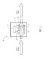
- FIG. 3is a perspective view of sensor device 12 (shown as assembled) with conductor 14 extending through aperture 110 .
- sensor device 12senses current flow through conductor 14 . Specifically, when current flows through conductor 14 , a current is induced in coil 104 . The amount of current induced in coil 104 is representative of the amount of current flowing through conductor 14 .
- coil 104is spaced a distance from conductor 14 . Accordingly, capacitance exists between coil 104 and conductor 14 . The capacitance may affect the accuracy of sensor device 12 at different operating voltages (e.g., a range from about 30V to about 277V).
- dielectric material 108is positioned within at least a portion of an air-gap 106 defined between coil 104 and conductor 14 .
- dielectric material 108affects and/or facilitates a reduction of the capacitance between coil 104 and conductor 14 , while permitting coil 104 and conductor 14 to remain in close proximity.
- the reduction in capacitanceenables sensor device 12 to sense current flowing through conductor 14 with improved accuracy, as compared to known Rogowski coils or other air-gap coils. More specifically, by reducing capacitance coupling between coil 104 and conductor 14 , the sensitivity to operating voltage is reduced. As a result, consistent current sensing is provided at different operating voltages across a range of different currents, including high and low currents. Accordingly, when sensor device 12 is included in utility meter 10 , one or more processes necessary for calibrating known sensor devices may be omitted.
- the consistency of sensor device 12 to accurately detect current across different operating voltagesmay permit meter control board 17 to use only one calibration coefficient for a plurality of operating voltages, as compared to known utility meters, which require multiple calibration coefficients for use at different voltages.
- the reduction in capacitance between coil 104 and conductor 14not only facilitates reducing and/or simplifying the calibration processes, but also facilitates reducing manufacturing cost, resources, and/or time with at least the same and often improved accuracy across operating voltage/current ranges.
- sensor device 12includes an enclosure 112 .
- Enclosure 112may be formed from a variety of materials and/or through a variety of fabrication processes.
- enclosure 112includes substantially only dielectric material 108 , such that dielectric material 108 is positioned about coil 104 , opposite aperture 110 .
- sensor device 12may be positioned about conductors 14 and proximate to at least one other conductor 15 (as shown in FIG. 1 ), and potentially proximate to conductor 16 .
- sensor device 12may provide improved accuracy when used in utility meter 10 having multiple conductors and/or when used in close proximity to one or more other conductors, as compared to known air-gap coils.
- enclosure 112may include one or more materials in addition to dielectric material 108 , such as non-dielectric materials or dielectric materials that have different characteristics.
- enclosure 112includes dielectric material 108 and an additive material, which is provided to support dielectric material 108 in one or more locations relative to coil 104 to enable it to perform as described herein.
- the additive materialmay include plastic materials, thermoplastic materials, thermoset materials, ceramic materials, metallic materials, wood materials, clay materials, organic materials, any mixture thereof, and/or other suitable materials.
- the additive materialmay be selected based on manufacturing techniques, dimensional stability, cost, moldability, workability, rigidity, and/or other characteristics of the material, etc.
- dielectric material 108when dielectric material 108 is a higher cost material (as compared to the additive material), the inclusion of an additive material may reduce the overall cost of sensor device 12 .
- one or more additive materialsmay be used to perform one or more additional functions, such as supporting dielectric material 108 , protecting and/or insulating coil 104 , etc.
- the additive materialmay be used as part of enclosure 112 in various embodiments. In the exemplary embodiment, however, an additive material is omitted, as enclosure 112 substantially only includes dielectric material 108 .
- Enclosure 112may be fabricated from the dielectric material, formed integrally from dielectric material 108 and at least one additive material, or assembled from separate dielectric material(s) 108 and additive material(s). Enclosure 112 and/or dielectric material 108 may be fabricated using one or more injection molding processes and/or other suitable fabrication processes. In the exemplary embodiment, enclosure 112 is constructed via a single injection molding process, in which dielectric material 108 is injected into a mold structured to form enclosure 112 .
- enclosure 112may be constructed from a multi-stage injection molding process.
- a multi-stage processan additive material is molded into a specific shape through an initial molding process. Subsequently, the molded additive material is positioned within a mold, and dielectric material 108 is injected into the mold. Dielectric material 108 flows into voids defined between the mold and/or the additive material, to form enclosure 112 from dielectric material 108 and additive material.
- a multi-stage molding processmay permit a relatively high-cost dielectric material to be specifically positioned relative to coils 104 such that desired performance as described herein is achieved, while still permitting other portions of enclosure 112 to be constructed from one or more relatively low cost materials.
- enclosure 112may be constructed by other fabrication techniques to provide dielectric material 108 throughout or at desired positions relative to coil 104 and/or conductor 14 .
- dielectric material 108is constructed separately from an additive material, and subsequently transformed and/or constructed with the additive material to form enclosure 112 .
- a tubular dielectric materialmay be inserted into an aperture formed by an additive material to form enclosure 112 .
- enclosure 112includes a mount 116 that defines aperture 110 .
- mount 116may include dielectric material 108 and/or another material. It should be appreciated that mount 116 may be formed in a variety of different shapes that are designed to receive and/or couple to various types, shapes, and/or orientations of conductors.
- mount 116defines an aperture that is structured to form a friction fit with a rectangular-shaped bus bar conductor.
- enclosure 112includes a first portion 118 and a second portion 120 .
- First portion 118is releasably coupled to second portion 120 such that substrate 102 and coil 104 are substantially enclosed therein.
- first portion 118is coupled to second portion 120 through at least one ship-lap joint to form enclosure 112 .
- first portion 118 and second portion 120may be coupled together through a variety of different methods, including, without limitation, one or more butt joints, screw joints, hinge joints, tab-slot arrangements, tongue-and-groove arrangements, fasteners, etc.
- enclosure 112has generally toroidal shape, as shown in FIG.
- enclosure embodimentsmay define any shape and/or size, that is sized and/or operates to at least partially enclose substrate 102 , coil 104 and/or shields, and that enables dielectric material 108 to perform as described herein.
- the thickness of dielectric material 108varies throughout enclosure 112 .
- the ship-lap joint between first portion 118 and second portion 120provides an overlap of first portion 118 and second portion 120 .
- first portion 118 and second portion 120each have a thickness of about 1.2 millimeters at aperture 110 .
- first portion 118 and second portion 120at least partially overlap at the ship-lap joint (along aperture 110 ) to create a total thickness of about 2.4 millimeters.
- first portion 118 and second portion 120are structured such that the total thickness about the outside of enclosure 112 at a minor ship-lap joint (opposite aperture 110 ) is less than about 1.2 millimeters. It should be appreciated that various methods of forming enclosure 112 may be used to provide one or more different thicknesses of enclosure 112 and/or dielectric material 108 .
- the thickness of enclosure 112 and/or dielectric material 108may be between about 0.5 millimeters and about 3.0 centimeters. In some embodiments, one or more thicknesses of enclosure 112 and/or dielectric material 108 are between about 1.0 millimeters and 6.0 millimeters. Further, in various embodiments, one or more thicknesses of enclosure 112 and/or dielectric material 108 are between about 1.0 millimeters and 4.0 millimeters. It should be appreciated that enclosure 112 and/or dielectric material 108 may have different thickness in other embodiments, potentially based on a method of assembly/fabrication, the characteristic(s) of a selected dielectric material, and/or desired performance characteristic(s). Further, other shapes, sizes, and/or joints for enclosure 112 may be used to at least partially enclosure coil 104 , while positioning dielectric material 108 relative to coil 104 to perform consistent with one or more aspects of the present disclosure.
- coil 104includes an exemplary Rogowski coil. It should be appreciated, however, that sensor device 12 may include a coil other than a Rogowski coil. Further, aspects of the present disclosure are not limited to only being used with a Rogowski coil as described and illustrated herein.
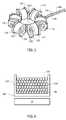
- FIG. 5is a perspective view of substrate 102 and coil 104 separated from enclosure 112 .
- substrate 102includes six bobbins 124 , 126 , 128 , 130 , 132 , and 134 (collectively referred to as bobbins 124 - 134 ).
- Each bobbin 124 - 134has a substantially circular cross-section, and more particular, is a right cylinder that includes flanges 135 at opposite ends that retain coil 104 .
- substrate 102may have a different number, shape, and/or size of bobbins.
- substrate 102may include five bobbins, eight bobbins, ten bobbins, thirty bobbins, or another even or odd number of bobbins. Further, substrate 102 may include bobbins having a different shape, and/or an ovular cross-section, an elliptical cross-section, or rectangular cross-section, etc. In still other embodiments, substrate 102 may include a different structure for supporting coil 104 , in addition to or other than flanges 135 . In at least one embodiment, coil 104 is sufficient rigid to omit substrate 102 .
- bobbins 124 - 134are coupled together via hinged joints 137 . More specifically, bobbins 124 and 126 are hingedly coupled to permit pivotal movement therebetween. In various embodiments, bobbins 124 - 134 may be linearly aligned to enable efficient winding of coil 104 and/or pivoted relative to one another to form a substantially circular shape, as illustrated in FIG. 5 .
- Each of bobbins 124 - 134 of substrate 102is a non-magnetic structure, such that bobbins 124 - 134 are constructed from one or more non-magnetic materials, including, for example, thermoplastic material, ceramic material, wood, material, or other kinds of suitable material(s).
- each of bobbins 124 - 134is fabricated from a dielectric material, potentially consistent with dielectric material 108 .
- substrate 102is shaped and/or sized to provide improved mounting within utility meter 10 and/or to a meter control board 17 , as compared to known sensor devices that include bulky magnetic cores.
- bobbins 124 - 134are formed separate from enclosure 112 . It should be appreciated, however, that bobbins 124 - 134 may be formed integrally with and/or form one or more portions of enclosure 112 in other sensor device embodiments.
- coil 104is wound multiple turns on each bobbin 124 - 134 . More specifically, in the exemplary embodiment, coil 104 includes a single magnet wire that enables coil 104 to be wound from bobbin 124 to bobbin 134 with several turns on each bobbin 124 - 134 , and then wound back to bobbin 124 with additional turns on each bobbin 124 - 134 . It should be appreciated that, in other embodiments, other different winding patterns on bobbins 124 - 134 may be used. Consistent with the above winding pattern across bobbins 124 - 134 , a first end and a second end of coil 104 terminates at bobbin 124 . The first end of coil 104 is terminated at lead wire 136 , and the second end of coil 104 is terminated at lead wire 138 , as shown in FIG. 7 , described further below.
- FIG. 6illustrates a partial cross-sectional view of sensor device 12 at bobbin 124 .
- bobbin 124includes a first shield 140 and a second shield 142 .
- First shield 140is positioned between bobbin 124 and coil 104 .
- Second shield 142is positioned adjacent to coil 104 and opposite from first shield 140 , such that coil 104 is positioned between first shield 140 and second shield 142 .
- Each bobbin 124 - 134includes substantially the same shield-coil-shield pattern as shown in FIG. 6 .
- bobbins 124 - 134may include other winding patterns, including winding patterns, in which the winding pattern varies from one bobbin to another bobbin.
- each shield 140 and 142provides a Faraday shield. More specifically, in this exemplary embodiment, first and second shields 140 and 142 behave substantially consistent with a Faraday cage, in order to facilitate reducing common mode noise on the sensor device 12 and/or to provide a low-pass filter for high frequency noise filtering. As a result, first and second shield 140 and 142 facilitate improved performance in the context of one or more industry standards for electromagnetic interface (EMI) and/or electromagnetic compatibility (EMC).
- EMIelectromagnetic interface
- EMCelectromagnetic compatibility
- first shield 140 and second shield 142are formed from a single magnet wire.
- first shield 140 and second shield 142may include any suitable materials, such as, without limitation, copper, aluminum or other nonferrous conducting material. More generally, the shielding material may be formed as a sheet, a tape, a wire, a spray and/or any other form that enables bobbins 124 - 134 to include shields 140 and 142 . As such, application of shields 140 and/or 142 may be formed, without limitation, via winding, wrapping, and/or spraying, for example. In various embodiments, first and second shield 140 and 142 may be formed separately from coil 104 and subsequently applied to coil 104 .
- sensor device 12includes three lead wires 136 , 138 , and 144 extending therefrom.
- FIG. 7illustrates a circuit diagram of the coupling of lead wires 136 , 138 , and 144 .
- first and second shields 140 and 142are formed from a single magnet wire, with each end coupled together and coupled to lead wire 144 .
- the first end of coil 104(formed from a single magnet wire) is coupled to lead wire 136
- a second end of coil 104is coupled to lead wire 138 .
- lead wires 136 , 138 , and 140extend from enclosure 112 and form a twisted wire set.
- lead wire 144behaves as a low pass filter element to inhibit noise from first shield 140 and/or second shield 142 from being injected into a return path of the current signal provided by sensor device 12 .
- the twisted wire sethas a length of at least about 0.25 inches. In other embodiments, twisted wire set may have a length of at least about 1.0 inches, or a length of at least about 3.0 inches. In further embodiments, twisted wire set may have a length of at least about 6.0 inches.
- lead wires and/or twisted wire setsmay be employed in other sensor device embodiments, possibly based on the performance of the lead wire and/or twisted wire set to function as a filter to inhibit the injection of noise into a current signal transmitted from sensor device 12 .
- FIGS. 8-9illustrates another exemplary sensor device 200 .
- sensor device 200includes a coil 204 and first and second shields 240 and 242 , which are substantially consistent with coil 104 and shields 140 and 142 described above.
- Sensor device 200includes four lead wires 236 , 238 , 244 , and 245 .
- each end of the magnet wire forming first shield 240 and second shield 240are coupled to separate lead wires 244 and 245 to create a filter element.
- two lead wires 236 and 238 coupled to coil 204As illustrated in FIG. 8 , lead wires 236 , 238 , 244 , and 245 form a twisted wire set, which functions substantially consistent with the twisted wire set described above with reference to FIG. 5 .
- each lead wire 244 and 245When coupled to meter control board 17 , each lead wire 244 and 245 may be coupled together and coupled to lead wire 238 . In some embodiments, twisted lead wires 244 and 245 may behave as a filter element. Additionally, or alternatively, a filter element may be coupled between lead wires 244 and 245 and lead wire 238 .
- Such filter elementsmay include, without limitation, a resistor-capacitor circuit, an inductor-capacitor circuit, a resistor-inductor circuit, and/or a resistor-inductor-capacitor circuit.
- each end of the magnet wire forming shields 140 and 142may be coupled together and coupled to lead wire 138 (i.e., one end of coil 104 ), rather than a separate lead wire 144
- sensor device 12may include lead wires 136 and 138 , while omitting lead wire 144 , thereby providing a two-wire sensor device 12 .
- some noise from first shield 140 and/or second shield 142may be injected into the return path of a current signal provided from sensor device 12 , while providing sufficient accuracy and/or repeatability for a desired operating environment.
- lead wiresmay be omitted from a sensor device embodiment to provide for mounting on a circuit board, such as meter control board 17 .
- a filter elementmay be provided by traces on meter control board 17 , with a sufficient length to perform as described above with reference to lead wire 144 .
- filter elementmay include a resistor-capacitor circuit, an inductor-capacitor circuit, a resistor-inductor circuit, and/or a resistor-inductor-capacitor circuit, to inhibit noise from first shield 140 and/or second shield 142 from being injected into a return path for the current signal provided by sensor device 12 .
- sensor device 12is operational between about 10 Hz to about 1000 Hz, and is substantially immune to signals outside this range. More specifically, conductor 14 may act as an antenna to pick up radio frequency (RF) signals and re-radiate the unwanted noise to sensor device 12 .
- First and second shield 140 and 142perform as a low-pass filter to inhibit injection of noise signals to provide a high signal-to-noise-ratio (SNR) output. More particularly, first and second shields 140 and 142 reject re-radiated RF signal (and/or other noise signals) to provide a high SNR for the output of sensor device 12 when sensing low current through conductor 14 .
- SNRsignal-to-noise-ratio
- first and second shields 140 and 142may permit one or more additional filter elements (for low and/or high current performance) to be omitted.
- first and second shields 140 and 142substantially inhibit EMI from affecting the accuracy of sensor device 12 . More specifically, first and second shields 140 and 142 facilitate inhibiting the effects of EMI sources positioned adjacent to sensor device 12 , such as adjacent electronics and/or devices intended to interfere with the accuracy of sensor device 12 and/or utility meter 10 . Additionally, by omitting a magnetic core, as compared to known sensors, sensor device 12 provides enhanced immunity to EMI affects on accuracy. As such, sensor device 12 provides a more robust and/or accurate current sensor device, as compared to other known sensor devices in the presence of one or more EMI sources.
- Accuracy of sensor device 12may be understood as a percentage of the actual value of current flowing through conductor 14 .
- sensor device 12performs within about ⁇ 0.2% of the actual value in the range between about 2 amps and about 200 amps. More specifically, sensor device 12 performs within Class 0.2, 0.1A to 200A at an operating voltage of between about 60V and about 600V, more specifically at about 240V, within an accuracy of 0.2%. It should be appreciated that sensor device 12 consistent with one or more aspects of the present disclosure may conform to one or more different accuracy standards at different operating currents/voltages, possibly depending on the intended application and/or one or more accuracy requirements associated with the intended application.
- sensor device 12for sensing current through a conductor. While these methods are described below with reference to sensor device 12 , it should be understood that the methods are not limited to sensor device 12 and may be utilized to fabricate other sensor device embodiments. Likewise, sensor device 12 and sensor device 200 may be fabricated from methods other than those described below.
- One exemplary method of fabricating sensor device 12 for sensing current through a conductor 14includes providing coil 104 with a plurality of turns about non-magnetic substrate 102 and positioning dielectric material 108 adjacent to coil 104 , such that when conductor 14 is disposed within aperture 110 defined by sensor device 12 , dielectric material 108 is positioned between conductor 14 and coil 104 .
- the exemplary methodmay include at least partially and/or substantially enclosing coil 104 and/or substrate 102 within enclosure 112 .
- Another exemplary method of fabricating sensor device 12 for sensing current through conductor 14includes providing Rogowski coil 104 and at least partially enclosing Rogowski coil 104 within dielectric material 108 such that, when Rogowski coil 104 is disposed about conductor 14 , dielectric material 108 is disposed between Rogowski coil 104 and the conductor 14 .
- Dielectric material 108has a dielectric constant of greater than or equal to about 3.5.
- the exemplary methodmay include assembling a first portion of an enclosure and a second portion of the enclosure with the Rogowski coil disposed therebetween to at least partially enclose the Rogowski coil.
- the enclosureincludes the dielectric material.
- the exemplary methodmay include forming the Rogowski coil on a substrate having a plurality of thermoplastic bobbins. Further, the exemplary method may include forming the plurality of thermoplastic bobbins from a dielectric material.
- Yet another exemplary method of fabricating a sensor device 12 for sensing current through a conductor 14includes winding a first shield of a magnet wire about each of a plurality of bobbins of a substrate, winding a coil about each of the plurality of bobbins of the substrate, and winding a second shield of magnet wire about each of the plurality of bobbins of the substrate.
- the exemplary methodmay include coupling a first end and a second end of the magnet wire to a reference lead 144 of sensor device 12 , coupling a first end of the coil to a first lead 136 of sensor device 12 , and coupling a second end of the coil to a second lead 138 of sensor device 12 . Further, the exemplary method may include at least partially enclosing the coil and the first and second shield within an enclosure, the enclosure comprising at least one dielectric material.
- Another exemplary method of fabricating a sensor device 12 for sensing current through a conductor 14includes providing sensor device 12 including non-magnetic substrate 102 defining aperture 110 , coil 104 having a plurality of coil turns about at least a portion of non-magnetic substrate 102 , first shield 140 disposed between each of substrate 102 and the plurality of coil turns, second shield 142 disposed proximate to the plurality of coil turns, opposite first shield 140 .
- the exemplary methodalso includes coupling lead wire 144 to at least one of first shield 140 and second shield 142 , coupling lead wire 136 to a first end of coil 104 , coupling lead wire 138 to a second end of coil 104 , and forming a twisted set of lead wires from lead wires 136 , 138 and 144 .
- coupling lead wire 144 to at least one of first shield 140 and second shield 142includes coupling lead wire 144 to each of the first shield 140 and second shield 142 .
- coupling lead wire to at least one of first shield and second shieldincludes coupling lead wire 244 to first shield 140 and coupling a lead wire 245 to second shield 142 .
- the sensor devices, utility meters, and methods described hereinmay provide a highly-accurate sensor device that provides an expanded operating range with reduced calibration requirements over known coil sensors.
- the disclosed dielectric materialmay provide reduced capacitance between a coil and one or more conductors, thereby providing improved accuracy across a range of currents and/or voltages. The improved accuracy may be realized with fewer calibration processes during manufacturing, resulting in reduced manufacturing cost and/or time.
- the disclosed shielding techniquesprovide improved rejection of EMI, originating from other electronics and/or tampering devices.
Landscapes
- Engineering & Computer Science (AREA)
- Power Engineering (AREA)
- Physics & Mathematics (AREA)
- General Physics & Mathematics (AREA)
- Measuring Instrument Details And Bridges, And Automatic Balancing Devices (AREA)
Abstract
Description
Claims (20)
Priority Applications (5)
| Application Number | Priority Date | Filing Date | Title |
|---|---|---|---|
| US13/228,924US8912807B2 (en) | 2011-09-09 | 2011-09-09 | Sensor devices and methods for use in sensing current through a conductor |
| JP2012192742AJP2013061327A (en) | 2011-09-09 | 2012-09-03 | Sensor devices and methods for use in sensing current through conductor |
| EP12183612.6AEP2568299B1 (en) | 2011-09-09 | 2012-09-07 | Sensor devices and methods for use in sensing current through a conductor |
| CN201210328043.3ACN102998506B (en) | 2011-09-09 | 2012-09-07 | Sensor devices and methods for use in sensing current through a conductor |
| ES12183612TES2879385T3 (en) | 2011-09-09 | 2012-09-07 | Sensing methods and devices for detecting current through a conductor |
Applications Claiming Priority (1)
| Application Number | Priority Date | Filing Date | Title |
|---|---|---|---|
| US13/228,924US8912807B2 (en) | 2011-09-09 | 2011-09-09 | Sensor devices and methods for use in sensing current through a conductor |
Publications (2)
| Publication Number | Publication Date |
|---|---|
| US20130063161A1 US20130063161A1 (en) | 2013-03-14 |
| US8912807B2true US8912807B2 (en) | 2014-12-16 |
Family
ID=46888919
Family Applications (1)
| Application Number | Title | Priority Date | Filing Date |
|---|---|---|---|
| US13/228,924Active2032-08-08US8912807B2 (en) | 2011-09-09 | 2011-09-09 | Sensor devices and methods for use in sensing current through a conductor |
Country Status (5)
| Country | Link |
|---|---|
| US (1) | US8912807B2 (en) |
| EP (1) | EP2568299B1 (en) |
| JP (1) | JP2013061327A (en) |
| CN (1) | CN102998506B (en) |
| ES (1) | ES2879385T3 (en) |
Cited By (2)
| Publication number | Priority date | Publication date | Assignee | Title |
|---|---|---|---|---|
| US20130214765A1 (en)* | 2010-10-04 | 2013-08-22 | Abb Technology Ag | Multifunctional measuring device |
| US9885590B2 (en)* | 2015-07-31 | 2018-02-06 | Robert Bosch Gmbh | Method for ascertaining a position of a rotor of an electrical machine |
Families Citing this family (15)
| Publication number | Priority date | Publication date | Assignee | Title |
|---|---|---|---|---|
| US9664711B2 (en)* | 2009-07-31 | 2017-05-30 | Pulse Electronics, Inc. | Current sensing devices and methods |
| US9823274B2 (en)* | 2009-07-31 | 2017-11-21 | Pulse Electronics, Inc. | Current sensing inductive devices |
| US9151782B2 (en)* | 2009-07-31 | 2015-10-06 | Pulse Electronics, Inc. | Current sensing devices and methods |
| US8872611B2 (en) | 2011-08-18 | 2014-10-28 | General Electric Company | Rogowski coil assemblies and methods for providing the same |
| US9081040B2 (en) | 2011-09-09 | 2015-07-14 | General Electric Company | Sensor devices and methods for use in sensing current through a conductor |
| US9304149B2 (en) | 2012-05-31 | 2016-04-05 | Pulse Electronics, Inc. | Current sensing devices and methods |
| US20140125446A1 (en) | 2012-11-07 | 2014-05-08 | Pulse Electronics, Inc. | Substrate inductive device methods and apparatus |
| GB201304743D0 (en)* | 2013-03-15 | 2013-05-01 | Dymo Nv | Label Printer |
| EP2980592A1 (en)* | 2014-07-30 | 2016-02-03 | General Electric Company | Sensor devices and methods for use in sensing current through a conductor |
| US9671434B2 (en) | 2014-08-08 | 2017-06-06 | Aclara Meters Llc | Sensor devices and methods for use in sensing current through a conductor |
| DE102015115264B3 (en)* | 2015-09-10 | 2016-08-18 | Semikron Elektronik Gmbh & Co. Kg | Centering device for a Rogowski coil, measuring device, power electronic device and a method for arranging a Rogowski coil |
| FR3053795B1 (en)* | 2016-07-08 | 2019-11-08 | Schneider Electric Industries Sas | APPARATUS FOR MEASURING ELECTRIC CURRENTS IN ELECTRICAL CONDUCTORS |
| CN106448999A (en)* | 2016-09-29 | 2017-02-22 | 湖北大二互科技股份有限公司 | Novel Rogowski coil with no positional deviation |
| CN106526276A (en)* | 2016-10-31 | 2017-03-22 | 国家电网公司 | Rogowski coil and skeleton, skeleton unit and skeleton manufacturing method thereof |
| JP7206803B2 (en)* | 2018-10-26 | 2023-01-18 | スミダコーポレーション株式会社 | Coil wire, current sensor material and current sensor |
Citations (41)
| Publication number | Priority date | Publication date | Assignee | Title |
|---|---|---|---|---|
| US3340353A (en) | 1966-01-28 | 1967-09-05 | Dow Chemical Co | Double-shielded electric cable |
| US4611191A (en) | 1984-05-21 | 1986-09-09 | Merlin Gerin | Non-magnetic core current sensor |
| US4616176A (en) | 1983-02-08 | 1986-10-07 | Hydro Quebec | Dynamic current transducer |
| US5414400A (en) | 1992-06-05 | 1995-05-09 | Gec Alsthom T&D Sa | Rogowski coil |
| US5442280A (en) | 1992-09-10 | 1995-08-15 | Gec Alstom T & D Sa | Device for measuring an electrical current in a conductor using a Rogowski coil |
| US5982265A (en) | 1995-02-09 | 1999-11-09 | Siemens Aktiengesellschaft | Current-detection coil for a current transformer |
| US6094044A (en) | 1998-05-07 | 2000-07-25 | Airpax Corporation, Llc | AC current sensor having high accuracy and large bandwidth |
| US6313623B1 (en) | 2000-02-03 | 2001-11-06 | Mcgraw-Edison Company | High precision rogowski coil |
| US6417661B1 (en) | 1997-08-28 | 2002-07-09 | General Electric Company | Self powered current sensor |
| US6521695B1 (en)* | 1996-06-21 | 2003-02-18 | Pirelli Cavi S.P.A. | Water tree resistant insulating composition |
| US20030112000A1 (en) | 2000-04-17 | 2003-06-19 | Thomas Sorenson Jr | Current measurement device |
| US6614218B1 (en) | 1998-04-22 | 2003-09-02 | Power Electronic Measurements Limited | Current measuring device |
| US6731193B2 (en) | 2001-01-27 | 2004-05-04 | Phoenix Contact Gmbh & Co. Kg | Printed circuit board-based current sensor |
| US6822547B2 (en) | 2001-10-29 | 2004-11-23 | Kabushiki Kaisha Toshiba | Current transformer |
| US20040257061A1 (en) | 2003-06-17 | 2004-12-23 | George De Buda Eric | Coreless current sensor |
| US20050248430A1 (en) | 2004-05-10 | 2005-11-10 | Areva T&D Sa | Current transformer with rogowski type windings, comprising an association of partial circuits forming a complete circuit |
| US20050253573A1 (en) | 2004-05-13 | 2005-11-17 | Gilles Budillon | Electric current measuring device, current sensor, electric trip unit and breaking device comprising such a measuring device |
| US7106162B2 (en) | 2002-09-30 | 2006-09-12 | Kabushiki Kaisha Toshiba | Current transformer |
| US20060220774A1 (en) | 2005-04-01 | 2006-10-05 | Veselin Skendzic | Precision printed circuit board based rogowski coil and method for manufacturing same |
| US7227441B2 (en) | 2005-02-04 | 2007-06-05 | Schweitzer Engineering Laboratories, Inc. | Precision Rogowski coil and method for manufacturing same |
| US20070152651A1 (en) | 2005-12-02 | 2007-07-05 | Matsushita Electric Works, Ltd. | Alternating current detection coil |
| US7253603B2 (en) | 2005-01-06 | 2007-08-07 | S & C Electric Co. | Current sensor arrangement |
| US20070285089A1 (en) | 2006-03-31 | 2007-12-13 | Daihen Corporation | Current detection printed board, voltage detection printed board, current/voltage detection printed board, current/voltage detector, current detector and voltage detector |
| US20070290695A1 (en) | 2004-05-29 | 2007-12-20 | Lem Heme Limited | Method and Apparatus for Measuring Current |
| US20080007249A1 (en) | 2006-07-06 | 2008-01-10 | Wilkerson Donovan E | Precision, temperature-compensated, shielded current measurement device |
| US20080036448A1 (en) | 2006-08-03 | 2008-02-14 | Kovach Daniel J | Method and system for measurement of current flows in fastener arrays |
| US20080079418A1 (en) | 2006-09-29 | 2008-04-03 | Gm Global Technology Operations, Inc. | High-precision rogowski current transformer |
| US20080106253A1 (en) | 2006-11-06 | 2008-05-08 | Cooper Technologies Company | Shielded Rogowski coil assembly and methods |
| US20080211484A1 (en) | 2007-01-19 | 2008-09-04 | Admmicro Properties, L.L.C. | Flexible current transformer assembly |
| US20080303511A1 (en) | 2005-11-28 | 2008-12-11 | Ladislav Grno | Precision flexible current sensor |
| US7538541B2 (en) | 2006-11-06 | 2009-05-26 | Cooper Technologies Company | Split Rogowski coil current measuring device and methods |
| WO2009139521A1 (en)* | 2008-05-13 | 2009-11-19 | Taehwatrans Co., Ltd. | Clamp type current sensor with rogowski coil |
| US20100013460A1 (en)* | 2006-12-21 | 2010-01-21 | Siemens Aktiengesellschaft | Rogowski Sensor and Method for Measuring a Current |
| CN201465698U (en) | 2009-08-14 | 2010-05-12 | 河南电力试验研究院 | A high-precision open-type Rogowski coil |
| US20110025304A1 (en)* | 2009-07-31 | 2011-02-03 | James Douglas Lint | Current sensing devices and methods |
| US20110025305A1 (en) | 2009-07-31 | 2011-02-03 | James Douglas Lint | Current sensing devices and methods |
| US20110043190A1 (en) | 2009-08-20 | 2011-02-24 | Farr Lawrence B | Rogowski coil, medium voltage electrical apparatus including the same, and method of providing electrostatic shielding for a rogowski coil |
| US20110148561A1 (en) | 2009-07-31 | 2011-06-23 | James Douglas Lint | Current sensing devices and methods |
| US20110204879A1 (en) | 2008-11-18 | 2011-08-25 | Alberto Bauer | Construction system for an electrical current and/or voltage sensor |
| US20120098519A1 (en) | 2010-10-26 | 2012-04-26 | Juds Mark A | Sensor assembly, trip unit including the same, and method of manufacturing a sensor assembly |
| US20130043967A1 (en) | 2011-08-18 | 2013-02-21 | General Electric Company | Rogowski coil assemblies and methods for providing the same |
Family Cites Families (12)
| Publication number | Priority date | Publication date | Assignee | Title |
|---|---|---|---|---|
| US5126192A (en)* | 1990-01-26 | 1992-06-30 | International Business Machines Corporation | Flame retardant, low dielectric constant microsphere filled laminate |
| US6710343B2 (en)* | 2000-03-22 | 2004-03-23 | The United States Of America As Represented By The Secretary Of The Navy | Photon detector |
| US6608495B2 (en)* | 2001-03-19 | 2003-08-19 | Applied Materials, Inc. | Eddy-optic sensor for object inspection |
| CN2565187Y (en)* | 2002-07-17 | 2003-08-06 | 天津市万得福变频技术应用开发有限公司 | Luoshi coil intelligent integrated protection relay for motor |
| CN2562191Y (en)* | 2002-07-17 | 2003-07-23 | 天津市万得福变频技术应用开发有限公司 | Rogowski coil current sensor |
| US7164263B2 (en)* | 2004-01-16 | 2007-01-16 | Fieldmetrics, Inc. | Current sensor |
| GB0409549D0 (en)* | 2004-04-29 | 2004-06-02 | Lem Heme Ltd | Current measurement apparatus |
| US7795877B2 (en)* | 2006-11-02 | 2010-09-14 | Current Technologies, Llc | Power line communication and power distribution parameter measurement system and method |
| JP5069978B2 (en)* | 2007-08-31 | 2012-11-07 | 株式会社ダイヘン | Printed circuit board for current / voltage detection and current / voltage detector |
| CN101644752A (en)* | 2009-08-14 | 2010-02-10 | 河南电力试验研究院 | Online accuracy detection method and system of current transformer |
| JP2011174756A (en)* | 2010-02-23 | 2011-09-08 | Autonetworks Technologies Ltd | Current detection device |
| CN102023244A (en)* | 2010-10-26 | 2011-04-20 | 江苏多维科技有限公司 | Independently-packaged electric meter sensor |
- 2011
- 2011-09-09USUS13/228,924patent/US8912807B2/enactiveActive
- 2012
- 2012-09-03JPJP2012192742Apatent/JP2013061327A/enactivePending
- 2012-09-07EPEP12183612.6Apatent/EP2568299B1/enactiveActive
- 2012-09-07CNCN201210328043.3Apatent/CN102998506B/enactiveActive
- 2012-09-07ESES12183612Tpatent/ES2879385T3/enactiveActive
Patent Citations (43)
| Publication number | Priority date | Publication date | Assignee | Title |
|---|---|---|---|---|
| US3340353A (en) | 1966-01-28 | 1967-09-05 | Dow Chemical Co | Double-shielded electric cable |
| US4616176A (en) | 1983-02-08 | 1986-10-07 | Hydro Quebec | Dynamic current transducer |
| US4611191A (en) | 1984-05-21 | 1986-09-09 | Merlin Gerin | Non-magnetic core current sensor |
| US5414400A (en) | 1992-06-05 | 1995-05-09 | Gec Alsthom T&D Sa | Rogowski coil |
| US5442280A (en) | 1992-09-10 | 1995-08-15 | Gec Alstom T & D Sa | Device for measuring an electrical current in a conductor using a Rogowski coil |
| US5461309A (en) | 1992-09-10 | 1995-10-24 | Gec Alsthom T&D Sa | Device for measuring temperature using a Rogowski coil |
| US5982265A (en) | 1995-02-09 | 1999-11-09 | Siemens Aktiengesellschaft | Current-detection coil for a current transformer |
| US6521695B1 (en)* | 1996-06-21 | 2003-02-18 | Pirelli Cavi S.P.A. | Water tree resistant insulating composition |
| US6417661B1 (en) | 1997-08-28 | 2002-07-09 | General Electric Company | Self powered current sensor |
| US6614218B1 (en) | 1998-04-22 | 2003-09-02 | Power Electronic Measurements Limited | Current measuring device |
| US6094044A (en) | 1998-05-07 | 2000-07-25 | Airpax Corporation, Llc | AC current sensor having high accuracy and large bandwidth |
| US6313623B1 (en) | 2000-02-03 | 2001-11-06 | Mcgraw-Edison Company | High precision rogowski coil |
| US20030112000A1 (en) | 2000-04-17 | 2003-06-19 | Thomas Sorenson Jr | Current measurement device |
| US6731193B2 (en) | 2001-01-27 | 2004-05-04 | Phoenix Contact Gmbh & Co. Kg | Printed circuit board-based current sensor |
| US6822547B2 (en) | 2001-10-29 | 2004-11-23 | Kabushiki Kaisha Toshiba | Current transformer |
| US7106162B2 (en) | 2002-09-30 | 2006-09-12 | Kabushiki Kaisha Toshiba | Current transformer |
| US20040257061A1 (en) | 2003-06-17 | 2004-12-23 | George De Buda Eric | Coreless current sensor |
| US20050248430A1 (en) | 2004-05-10 | 2005-11-10 | Areva T&D Sa | Current transformer with rogowski type windings, comprising an association of partial circuits forming a complete circuit |
| US20050253573A1 (en) | 2004-05-13 | 2005-11-17 | Gilles Budillon | Electric current measuring device, current sensor, electric trip unit and breaking device comprising such a measuring device |
| US20070290695A1 (en) | 2004-05-29 | 2007-12-20 | Lem Heme Limited | Method and Apparatus for Measuring Current |
| US7253603B2 (en) | 2005-01-06 | 2007-08-07 | S & C Electric Co. | Current sensor arrangement |
| US7227441B2 (en) | 2005-02-04 | 2007-06-05 | Schweitzer Engineering Laboratories, Inc. | Precision Rogowski coil and method for manufacturing same |
| US7474192B2 (en) | 2005-02-04 | 2009-01-06 | Schweitzer Engineering Laboratories, Inc. | Precision Rogowski coil and method for manufacturing same |
| US20060220774A1 (en) | 2005-04-01 | 2006-10-05 | Veselin Skendzic | Precision printed circuit board based rogowski coil and method for manufacturing same |
| US20080303511A1 (en) | 2005-11-28 | 2008-12-11 | Ladislav Grno | Precision flexible current sensor |
| US20070152651A1 (en) | 2005-12-02 | 2007-07-05 | Matsushita Electric Works, Ltd. | Alternating current detection coil |
| US20070285089A1 (en) | 2006-03-31 | 2007-12-13 | Daihen Corporation | Current detection printed board, voltage detection printed board, current/voltage detection printed board, current/voltage detector, current detector and voltage detector |
| US20080007249A1 (en) | 2006-07-06 | 2008-01-10 | Wilkerson Donovan E | Precision, temperature-compensated, shielded current measurement device |
| US20080036448A1 (en) | 2006-08-03 | 2008-02-14 | Kovach Daniel J | Method and system for measurement of current flows in fastener arrays |
| US20080079418A1 (en) | 2006-09-29 | 2008-04-03 | Gm Global Technology Operations, Inc. | High-precision rogowski current transformer |
| US7538541B2 (en) | 2006-11-06 | 2009-05-26 | Cooper Technologies Company | Split Rogowski coil current measuring device and methods |
| US20080106253A1 (en) | 2006-11-06 | 2008-05-08 | Cooper Technologies Company | Shielded Rogowski coil assembly and methods |
| US20100013460A1 (en)* | 2006-12-21 | 2010-01-21 | Siemens Aktiengesellschaft | Rogowski Sensor and Method for Measuring a Current |
| US20080211484A1 (en) | 2007-01-19 | 2008-09-04 | Admmicro Properties, L.L.C. | Flexible current transformer assembly |
| WO2009139521A1 (en)* | 2008-05-13 | 2009-11-19 | Taehwatrans Co., Ltd. | Clamp type current sensor with rogowski coil |
| US20110204879A1 (en) | 2008-11-18 | 2011-08-25 | Alberto Bauer | Construction system for an electrical current and/or voltage sensor |
| US20110025304A1 (en)* | 2009-07-31 | 2011-02-03 | James Douglas Lint | Current sensing devices and methods |
| US20110025305A1 (en) | 2009-07-31 | 2011-02-03 | James Douglas Lint | Current sensing devices and methods |
| US20110148561A1 (en) | 2009-07-31 | 2011-06-23 | James Douglas Lint | Current sensing devices and methods |
| CN201465698U (en) | 2009-08-14 | 2010-05-12 | 河南电力试验研究院 | A high-precision open-type Rogowski coil |
| US20110043190A1 (en) | 2009-08-20 | 2011-02-24 | Farr Lawrence B | Rogowski coil, medium voltage electrical apparatus including the same, and method of providing electrostatic shielding for a rogowski coil |
| US20120098519A1 (en) | 2010-10-26 | 2012-04-26 | Juds Mark A | Sensor assembly, trip unit including the same, and method of manufacturing a sensor assembly |
| US20130043967A1 (en) | 2011-08-18 | 2013-02-21 | General Electric Company | Rogowski coil assemblies and methods for providing the same |
Non-Patent Citations (18)
| Title |
|---|
| Bakelite, http://en.wikipedia.org/wiki/Bakelite.* |
| Clamp-On Weather Proof Rogowski Coil, available at http://www.taehwatrans.com/bbs/board.php?bo-table=product-02&wr-id=10 on Apr. 3, 2010.* |
| Clamp-On Weather Proof Rogowski Coil, available at http://www.taehwatrans.com/bbs/board.php?bo—table=product—02&wr—id=10 on Apr. 3, 2010.* |
| Co-pending U.S. Appl. No. 13/228,968, filed Sep. 9, 2011, entitled Sensor Devices and Methods for Use in Sensing Current Through a Conductor, by Chamarti et al. |
| Co-pending U.S. Appl. No. 13/229,002, filed Sep. 9, 2011 entitled Sensor Devices and Methods for Use in Sensing Current Through a Conductor, by Chamarti et al. |
| Co-pending U.S. Appl. No. 13/229,038, filed Sep. 9, 2011, entitled Sensor Devices and Methods for Use in Sensing Current Through a Conductor, by Chamarti et al. |
| Dakin, Insulating Materials, Standard Handbook for Electrical Engineers, McGraw Hill, section 4, pp. 124-129, 1969.* |
| Dielectric Constants of Various Materials Table, http://www.csgnetwork.com/dieconstantstable.html.* |
| DuPont(TM) Crastin® Polybutylene Terephthalate (PBT) polyester resin, http://www2.dupont.com/Plastics/en-US/Products/Crastin/Crastin.html.* |
| DuPont™ Crastin® Polybutylene Terephthalate (PBT) polyester resin, http://www2.dupont.com/Plastics/en—US/Products/Crastin/Crastin.html.* |
| Polybutylene terephthalate, available at http://en.wikipedia.org/wiki/Polybutylene-terephthalate on Jun. 18, 2010.* |
| Polybutylene terephthalate, available at http://en.wikipedia.org/wiki/Polybutylene—terephthalate on Jun. 18, 2010.* |
| Rogowski coil, available at http://en.wikipedia.org/wiki/Rogowski-coil on Jun. 7, 2010.* |
| Rogowski coil, available at http://en.wikipedia.org/wiki/Rogowski—coil on Jun. 7, 2010.* |
| Search Report issued in connection with EP Application No. 12180314.2, Nov. 29, 2012. |
| Synthetic Resin, http://en.wikipedia.org/wiki/Synthetic-resin.* |
| Synthetic Resin, http://en.wikipedia.org/wiki/Synthetic—resin.* |
| Thermoplastic Resin, available at http://www.trivenichemical.com/resin4.html. |
Cited By (3)
| Publication number | Priority date | Publication date | Assignee | Title |
|---|---|---|---|---|
| US20130214765A1 (en)* | 2010-10-04 | 2013-08-22 | Abb Technology Ag | Multifunctional measuring device |
| US9297829B2 (en)* | 2010-10-04 | 2016-03-29 | Abb Technology Ag | Multifunctional measuring device |
| US9885590B2 (en)* | 2015-07-31 | 2018-02-06 | Robert Bosch Gmbh | Method for ascertaining a position of a rotor of an electrical machine |
Also Published As
| Publication number | Publication date |
|---|---|
| US20130063161A1 (en) | 2013-03-14 |
| EP2568299A3 (en) | 2017-07-26 |
| CN102998506A (en) | 2013-03-27 |
| EP2568299B1 (en) | 2021-04-14 |
| JP2013061327A (en) | 2013-04-04 |
| ES2879385T3 (en) | 2021-11-22 |
| CN102998506B (en) | 2017-05-03 |
| EP2568299A2 (en) | 2013-03-13 |
Similar Documents
| Publication | Publication Date | Title |
|---|---|---|
| US9075091B2 (en) | Sensor devices and methods for use in sensing current through a conductor | |
| US8912807B2 (en) | Sensor devices and methods for use in sensing current through a conductor | |
| US9429595B2 (en) | Sensor devices and methods for use in sensing current through a conductor | |
| US8829888B2 (en) | Sensor devices and methods for use in sensing current through a conductor | |
| US9081040B2 (en) | Sensor devices and methods for use in sensing current through a conductor | |
| CA2897856C (en) | Sensor devices and methods for use in sensing current through a conductor | |
| CA2898935C (en) | Sensor devices and methods for use in sensing current through a conductor | |
| JP6231265B2 (en) | Rogowski coil assembly and method for providing the same | |
| HK1221773B (en) | Sensor devices and methods for use in sensing current through a conductor |
Legal Events
| Date | Code | Title | Description |
|---|---|---|---|
| AS | Assignment | Owner name:GENERAL ELECTRIC COMPANY, NEW YORK Free format text:ASSIGNMENT OF ASSIGNORS INTEREST;ASSIGNORS:CHAMARTI, SUBRAMANYAM SATYASURYA;BIETZ, STEVEN LEE;SIGNING DATES FROM 20110908 TO 20110909;REEL/FRAME:026880/0900 | |
| FEPP | Fee payment procedure | Free format text:PAYOR NUMBER ASSIGNED (ORIGINAL EVENT CODE: ASPN); ENTITY STATUS OF PATENT OWNER: LARGE ENTITY | |
| STCF | Information on status: patent grant | Free format text:PATENTED CASE | |
| AS | Assignment | Owner name:PNC BANK, NATIONAL ASSOCIATION, PENNSYLVANIA Free format text:SECURITY INTEREST;ASSIGNOR:MRH METERS LLC;REEL/FRAME:037359/0375 Effective date:20151221 Owner name:CERBERUS BUSINESS FINANCE, LLC, AS AGENT, NEW YORK Free format text:PATENT SECURITY AGREEMENT;ASSIGNOR:MRH METERS LLC;REEL/FRAME:037362/0603 Effective date:20151221 | |
| AS | Assignment | Owner name:MRH METERS LLC (F/K/A LJF METERS LLC), FLORIDA Free format text:ASSIGNMENT OF ASSIGNORS INTEREST;ASSIGNOR:GENERAL ELECTRIC COMPANY;REEL/FRAME:037398/0877 Effective date:20151221 | |
| AS | Assignment | Owner name:ACLARA METERS LLC, FLORIDA Free format text:CHANGE OF NAME;ASSIGNOR:MRH METERS LLC;REEL/FRAME:037852/0418 Effective date:20160115 | |
| AS | Assignment | Owner name:MORGAN STANLEY SENIOR FUNDING, INC., AS COLLATERAL Free format text:SECURITY AGREEMENT;ASSIGNORS:ACLARA TECHNOLOGIES LLC;ACLARA METERS LLC;REEL/FRAME:039872/0227 Effective date:20160829 Owner name:ACLARA TECHNOLOGIES LLC, MISSOURI Free format text:RELEASE OF SECURITY INTEREST IN PATENTS;ASSIGNOR:CERBERUS BUSINESS FINANCE, LLC;REEL/FRAME:039880/0908 Effective date:20160829 Owner name:ACLARA METERS LLC F/K/A MRH METERS LLC, MISSOURI Free format text:RELEASE OF SECURITY INTEREST IN PATENTS;ASSIGNOR:CERBERUS BUSINESS FINANCE, LLC;REEL/FRAME:039880/0908 Effective date:20160829 | |
| FEPP | Fee payment procedure | Free format text:PAYOR NUMBER ASSIGNED (ORIGINAL EVENT CODE: ASPN); ENTITY STATUS OF PATENT OWNER: LARGE ENTITY Free format text:PAYER NUMBER DE-ASSIGNED (ORIGINAL EVENT CODE: RMPN); ENTITY STATUS OF PATENT OWNER: LARGE ENTITY | |
| AS | Assignment | Owner name:ACLARA TECHNOLOGIES LLC, MISSOURI Free format text:RELEASE BY SECURED PARTY;ASSIGNOR:MORGAN STANLEY SENIOR FUNDING, INC.;REEL/FRAME:045245/0231 Effective date:20180202 Owner name:ACLARA METERS LLC, MISSOURI Free format text:RELEASE BY SECURED PARTY;ASSIGNOR:MORGAN STANLEY SENIOR FUNDING, INC.;REEL/FRAME:045245/0231 Effective date:20180202 | |
| AS | Assignment | Owner name:MRH METERS LLC, MISSOURI Free format text:TERMINATION AND RELEASE OF PATENT SECURITY AGREEMENT;ASSIGNOR:PNC BANK, NATIONAL ASSOCIATION;REEL/FRAME:046117/0792 Effective date:20180202 | |
| MAFP | Maintenance fee payment | Free format text:PAYMENT OF MAINTENANCE FEE, 4TH YEAR, LARGE ENTITY (ORIGINAL EVENT CODE: M1551) Year of fee payment:4 | |
| MAFP | Maintenance fee payment | Free format text:PAYMENT OF MAINTENANCE FEE, 8TH YEAR, LARGE ENTITY (ORIGINAL EVENT CODE: M1552); ENTITY STATUS OF PATENT OWNER: LARGE ENTITY Year of fee payment:8 |