US8912781B2 - Integrated circuit switching power supply controller with selectable buck mode operation - Google Patents
Integrated circuit switching power supply controller with selectable buck mode operationDownload PDFInfo
- Publication number
- US8912781B2 US8912781B2US12/973,003US97300310AUS8912781B2US 8912781 B2US8912781 B2US 8912781B2US 97300310 AUS97300310 AUS 97300310AUS 8912781 B2US8912781 B2US 8912781B2
- Authority
- US
- United States
- Prior art keywords
- power supply
- operating mode
- circuit
- integrated circuit
- peak
- Prior art date
- Legal status (The legal status is an assumption and is not a legal conclusion. Google has not performed a legal analysis and makes no representation as to the accuracy of the status listed.)
- Expired - Fee Related, expires
Links
- 238000004804windingMethods0.000claimsdescription32
- 238000000034methodMethods0.000claimsdescription12
- 238000001514detection methodMethods0.000claimsdescription6
- 230000008878couplingEffects0.000claims3
- 238000010168coupling processMethods0.000claims3
- 238000005859coupling reactionMethods0.000claims3
- 238000010586diagramMethods0.000description8
- 239000003990capacitorSubstances0.000description6
- 238000002955isolationMethods0.000description2
- 230000004913activationEffects0.000description1
- 239000007795chemical reaction productSubstances0.000description1
- 238000001914filtrationMethods0.000description1
- 230000000717retained effectEffects0.000description1
- 230000000630rising effectEffects0.000description1
Images


Classifications
- H—ELECTRICITY
- H02—GENERATION; CONVERSION OR DISTRIBUTION OF ELECTRIC POWER
- H02M—APPARATUS FOR CONVERSION BETWEEN AC AND AC, BETWEEN AC AND DC, OR BETWEEN DC AND DC, AND FOR USE WITH MAINS OR SIMILAR POWER SUPPLY SYSTEMS; CONVERSION OF DC OR AC INPUT POWER INTO SURGE OUTPUT POWER; CONTROL OR REGULATION THEREOF
- H02M3/00—Conversion of DC power input into DC power output
- H02M3/22—Conversion of DC power input into DC power output with intermediate conversion into AC
- H02M3/24—Conversion of DC power input into DC power output with intermediate conversion into AC by static converters
- H02M3/28—Conversion of DC power input into DC power output with intermediate conversion into AC by static converters using discharge tubes with control electrode or semiconductor devices with control electrode to produce the intermediate AC
- H02M3/325—Conversion of DC power input into DC power output with intermediate conversion into AC by static converters using discharge tubes with control electrode or semiconductor devices with control electrode to produce the intermediate AC using devices of a triode or a transistor type requiring continuous application of a control signal
- H02M3/335—Conversion of DC power input into DC power output with intermediate conversion into AC by static converters using discharge tubes with control electrode or semiconductor devices with control electrode to produce the intermediate AC using devices of a triode or a transistor type requiring continuous application of a control signal using semiconductor devices only
- H02M3/33507—Conversion of DC power input into DC power output with intermediate conversion into AC by static converters using discharge tubes with control electrode or semiconductor devices with control electrode to produce the intermediate AC using devices of a triode or a transistor type requiring continuous application of a control signal using semiconductor devices only with automatic control of the output voltage or current, e.g. flyback converters
- H02M3/33523—Conversion of DC power input into DC power output with intermediate conversion into AC by static converters using discharge tubes with control electrode or semiconductor devices with control electrode to produce the intermediate AC using devices of a triode or a transistor type requiring continuous application of a control signal using semiconductor devices only with automatic control of the output voltage or current, e.g. flyback converters with galvanic isolation between input and output of both the power stage and the feedback loop
- H—ELECTRICITY
- H02—GENERATION; CONVERSION OR DISTRIBUTION OF ELECTRIC POWER
- H02M—APPARATUS FOR CONVERSION BETWEEN AC AND AC, BETWEEN AC AND DC, OR BETWEEN DC AND DC, AND FOR USE WITH MAINS OR SIMILAR POWER SUPPLY SYSTEMS; CONVERSION OF DC OR AC INPUT POWER INTO SURGE OUTPUT POWER; CONTROL OR REGULATION THEREOF
- H02M3/00—Conversion of DC power input into DC power output
- H02M3/02—Conversion of DC power input into DC power output without intermediate conversion into AC
- H02M3/04—Conversion of DC power input into DC power output without intermediate conversion into AC by static converters
- H02M3/10—Conversion of DC power input into DC power output without intermediate conversion into AC by static converters using discharge tubes with control electrode or semiconductor devices with control electrode
- H02M3/145—Conversion of DC power input into DC power output without intermediate conversion into AC by static converters using discharge tubes with control electrode or semiconductor devices with control electrode using devices of a triode or transistor type requiring continuous application of a control signal
- H02M3/155—Conversion of DC power input into DC power output without intermediate conversion into AC by static converters using discharge tubes with control electrode or semiconductor devices with control electrode using devices of a triode or transistor type requiring continuous application of a control signal using semiconductor devices only
- H02M3/156—Conversion of DC power input into DC power output without intermediate conversion into AC by static converters using discharge tubes with control electrode or semiconductor devices with control electrode using devices of a triode or transistor type requiring continuous application of a control signal using semiconductor devices only with automatic control of output voltage or current, e.g. switching regulators
- H02M3/1563—Conversion of DC power input into DC power output without intermediate conversion into AC by static converters using discharge tubes with control electrode or semiconductor devices with control electrode using devices of a triode or transistor type requiring continuous application of a control signal using semiconductor devices only with automatic control of output voltage or current, e.g. switching regulators without using an external clock
- H05B33/0815—
- H05B33/0851—
- H—ELECTRICITY
- H05—ELECTRIC TECHNIQUES NOT OTHERWISE PROVIDED FOR
- H05B—ELECTRIC HEATING; ELECTRIC LIGHT SOURCES NOT OTHERWISE PROVIDED FOR; CIRCUIT ARRANGEMENTS FOR ELECTRIC LIGHT SOURCES, IN GENERAL
- H05B45/00—Circuit arrangements for operating light-emitting diodes [LED]
- H05B45/10—Controlling the intensity of the light
- H—ELECTRICITY
- H05—ELECTRIC TECHNIQUES NOT OTHERWISE PROVIDED FOR
- H05B—ELECTRIC HEATING; ELECTRIC LIGHT SOURCES NOT OTHERWISE PROVIDED FOR; CIRCUIT ARRANGEMENTS FOR ELECTRIC LIGHT SOURCES, IN GENERAL
- H05B45/00—Circuit arrangements for operating light-emitting diodes [LED]
- H05B45/30—Driver circuits
- H05B45/37—Converter circuits
- H05B45/3725—Switched mode power supply [SMPS]
- H05B45/375—Switched mode power supply [SMPS] using buck topology
- H—ELECTRICITY
- H05—ELECTRIC TECHNIQUES NOT OTHERWISE PROVIDED FOR
- H05B—ELECTRIC HEATING; ELECTRIC LIGHT SOURCES NOT OTHERWISE PROVIDED FOR; CIRCUIT ARRANGEMENTS FOR ELECTRIC LIGHT SOURCES, IN GENERAL
- H05B45/00—Circuit arrangements for operating light-emitting diodes [LED]
- H05B45/30—Driver circuits
- H05B45/37—Converter circuits
- H05B45/3725—Switched mode power supply [SMPS]
- H05B45/382—Switched mode power supply [SMPS] with galvanic isolation between input and output
- H—ELECTRICITY
- H05—ELECTRIC TECHNIQUES NOT OTHERWISE PROVIDED FOR
- H05B—ELECTRIC HEATING; ELECTRIC LIGHT SOURCES NOT OTHERWISE PROVIDED FOR; CIRCUIT ARRANGEMENTS FOR ELECTRIC LIGHT SOURCES, IN GENERAL
- H05B45/00—Circuit arrangements for operating light-emitting diodes [LED]
- H05B45/30—Driver circuits
- H05B45/37—Converter circuits
- H05B45/3725—Switched mode power supply [SMPS]
- H05B45/385—Switched mode power supply [SMPS] using flyback topology
- Y—GENERAL TAGGING OF NEW TECHNOLOGICAL DEVELOPMENTS; GENERAL TAGGING OF CROSS-SECTIONAL TECHNOLOGIES SPANNING OVER SEVERAL SECTIONS OF THE IPC; TECHNICAL SUBJECTS COVERED BY FORMER USPC CROSS-REFERENCE ART COLLECTIONS [XRACs] AND DIGESTS
- Y02—TECHNOLOGIES OR APPLICATIONS FOR MITIGATION OR ADAPTATION AGAINST CLIMATE CHANGE
- Y02B—CLIMATE CHANGE MITIGATION TECHNOLOGIES RELATED TO BUILDINGS, e.g. HOUSING, HOUSE APPLIANCES OR RELATED END-USER APPLICATIONS
- Y02B20/00—Energy efficient lighting technologies, e.g. halogen lamps or gas discharge lamps
- Y02B20/30—Semiconductor lamps, e.g. solid state lamps [SSL] light emitting diodes [LED] or organic LED [OLED]
- Y02B20/347—
Definitions
- the present inventionrelates generally to switching power supply circuits, and in particular to an integrated circuit controller for controlling a switching power supply circuit and having selectable buck mode operation.
- Lighting control and power supply integrated circuitsare in common use in both electronic systems and in replaceable consumer lighting devices, e.g., light-emitting-diode (LED) and compact fluorescent lamp (CFL) replacements for traditional incandescent light bulbs.
- LEDlight-emitting-diode
- CFLcompact fluorescent lamp
- the inventionis embodied in an integrated circuit (IC) and its method of operation.
- the ICis a controlled-current switching power supply controller.
- the IChas multiple selectable operating modes, including a buck converter operating mode and another operating mode, which may be a flyback converter operating mode.
- the IC controllercontrols the cycle rate of the converter by controlling one or more switching devices that may be internal to, or external to the IC, in order to maintain a fixed or variable output current level.
- FIG. 1is a block diagram depicting a flyback converter power supply circuit including a switching power supply controller IC 10 in accordance with an embodiment of the present invention.
- FIG. 2is a timing diagram illustrating signals within the circuit of FIG. 1 .
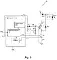
- FIG. 3is a block diagram depicting a buck converter power supply circuit including switching power supply controller IC 10 in accordance with another embodiment of the present invention.
- FIG. 4is a timing diagram illustrating signals within the circuit of FIG. 3 .
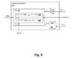
- FIG. 5is a block diagram depicting details of switching power supply controller IC 10 in accordance with an embodiment of the present invention.
- the present inventionencompasses power supply controller integrated circuits (ICs) and their methods of operation.
- power supplies implemented using the controller ICsprovide constant or variable output current levels to lighting devices such as light-emitting diodes (LEDs).
- the brightness of the LEDsmay be controlled by changing the output current level according to a dimming value.
- the ICshave a selectable mode of operation, including a buck converter mode and one other mode.
- the one other modemay be a flyback converter operating mode or a mode supporting another topology.
- the ICsthereby support multiple switching power supply topologies.
- a transformer T 1provides a magnetic storage element through which energy is transferred to an LED LED 1 through diode D 1 and to charge capacitor C 1 , which provides filtering of the ripple voltage produced by the switching action of the power supply circuit 5 .
- Transformer T 1further provides isolation between a primary side circuit coupled to a rectified line voltage source +V S and LED LED 1 , which may be a string of series connected LEDs. While the exemplary lighting devices are LEDs in the Figure, lighting device LED 1 can alternatively be another type of lighting device, in accordance with other embodiments of the invention. Further, the techniques of the present invention may be used in other applications requiring controlled-current power supplies, such as motor control applications.
- An integrated circuit (IC) 10provides a primary-side controller that operates a switching transistor N 1 , which is illustrated as external to IC 10 , but that alternatively may be included within IC 10 .
- a switching controller 12provides a pulse frequency modulated (PFM) gate control signal drive to vary the cycle rate of the switching power supply circuit.
- PFMpulse frequency modulated
- Switching controlleralso receives an indication of the selected operating mode of integrated circuit 10 , which in the illustration is a logical input signal provided from a terminal of integrated circuit 10 , that when in a logic low condition (ground) selects a flyback operating mode, as shown.
- the gate of switching transistor N 1is controlled by the PFM switching signal to control the amount of energy applied to the primary winding of transformer T 1 , according to dimming values DIM, which may be provided by a source internal or external to integrated circuit 10 .
- the current supplied to LED LED 1is thereby controlled by switching controller 12 , according to feedback values provided by a current sense circuit 16 , which senses the magnitude of primary winding current I PRI of transformer T 1 while switching transistor N 1 is conducting, and from a voltage sensing circuit 14 that senses a voltage across the primary winding of transformer T 1 , so that the end of the flyback interval (when switching transistor N 1 is not conducting and secondary winding current I SEC is non-zero) can be determined.
- primary winding current I PRIis measured by including a sense resistor R 1 connected between the source of transistor N 1 and ground.
- Current sense circuit 16determines an indication of the peak current I PEAK through the primary winding of transformer T 1 , by detecting the peak value of a voltage V sense generated across sense resistor R 1 at each cycle. The value of peak current I PEAK is retained (sampled) to use in controlling the next switching cycle(s) of switching controller 12 .
- the duration of the flyback interval, during which secondary winding current I SEC is non-zero and capacitor C 1 is being chargedis determined by voltage sensing circuit 14 , which determines when the voltage across the primary winding of transformer T 1 is negative and non-zero, i.e., the duration of the period t fly extending from the turn-off time of transistor N 1 until diode D 1 ceases conduction.
- Voltage sensing circuit 14generates logic signal z, which is active only during flyback interval t fly . Both the sampled peak primary winding current I peak and the duration of the flyback interval t fly , will be used in determining the cycle rate of the next switching cycle(s) of gate control signal drive.
- a first charging interval t chg between times t 0 and t 1stores energy in transformer T 1 determined by the peak current I peak of primary winding current I PRI at time t 1 .
- the rising value of primary winding current I PRIis caused by activation of switching transistor N 1 according to gate drive signal drive.
- flyback interval t fly between times t 1 and t 2the flyback secondary current I SEC from the secondary winding of transformer T 1 passes through diode D 1 to charge capacitor C 1 , to power LED LED 1 .
- the switching cyclerepeats after the cycle time t cyc has elapsed, which determines the cycle rate of the switching power supply circuit.
- the cycle time formula to generate particular current level I OUTis different, as will be illustrated below.
- integrated circuit 10In order to provide proper operation, integrated circuit 10 must be operated in the mode that corresponds to the topology of the switching power supply circuit in which integrated circuit 10 is installed, and the component values provided in the circuit must be determined for proper operation, e.g., the core of transformer T 1 (or inductor L 1 used in the non-isolated buck converter topology illustrated below) must be sized to avoid saturation during charging interval t chg , along with other usual considerations in switching power supply design and component selection.
- Buck switching power supply circuit 5 Ais similar to flyback switching power supply circuit 5 of FIG. 1 , so only differences between them will be described below.
- the buck operating mode of integrated circuit 10is selected by strapping input terminal BUCK to power supply voltage +V DD .
- An inductor L 1provides the magnetic storage element through which energy is transferred to LED LED 1 .
- currentis supplied through LED LED 1 when transistor N 1 is conducting by conduction of diode D 10 , and also during the flyback interval by conduction of diode D 11 .
- buck switching power supply circuit 5 Ais in the detection of the flyback interval duration t fly .
- An auxiliary windingis provided on inductor L 1 and is used to provide a power supply voltage +V DD for powering integrated circuit 10 through rectifier diode D 12 , filter resistor R 2 and filter capacitor C 10 .
- a voltage divider formed by resistors R 3 and R 4provides an input voltage signal to voltage sense circuit 14 A, which is a scaled version of auxiliary winding voltage V aux .
- voltage sense circuit 14 Awhich may be identical to voltage sense circuit 14 of FIG.
- the auxiliary winding circuit shown in FIG. 3can be used as an alternative to detection of primary winding voltage V PRI in the circuit of FIG. 1 , in accordance with another embodiment of the present invention, by providing an auxiliary winding on transformer T 1 , which may also be used to provide a power supply voltage +V DD for powering integrated circuit 10 , as in the circuit of FIG. 3 .
- inductor current I Lhas both positive and negative portions, the positive portion corresponding to the time when gate control signal drive is active, and the negative portion corresponding to flyback interval t fly .
- Charging interval t chg between times t 0 and t 1stores energy in inductor L 1 determined by the peak current I peak of inductor current I L at time t 1 .
- the current through inductor L 1is also the same as charging current I CHG that charges capacitor C 1 during charging interval t chg .
- Charging current I CHGalso charges capacitor C 1 during flyback interval t fly due to conduction of diode D 11 , leading to the triangular shape of the waveform of charging current I CHG .
- switching controller 12within integrated circuit 10 is shown in accordance with an embodiment of the present invention.
- the depicted circuitis exemplary, and provides only one particular example of a circuit that may be used to implement switching controller 12 .
- current sensing circuit 16is subsumed in switching controller 12 and is provided by an analog-to-digital converter (ADC) 52 and logic or a program within pulse frequency modulator (PFM) 50 that detects the peak current level I PEAK .
- Voltage sensing circuit 14is also subsumed in switching controller 12 , the function of which is provided by a comparator K 1 that generates logic signal z, indicative of the polarity of the auxiliary (or primary) winding voltage.
- PFM 50determines the duration of flyback interval t fly .
- one of buck converter algorithm 54 A or flyback converter algorithm 54 Bis selected to generate gate control signal drive.
Landscapes
- Engineering & Computer Science (AREA)
- Power Engineering (AREA)
- Dc-Dc Converters (AREA)
- Circuit Arrangement For Electric Light Sources In General (AREA)
Abstract
Description
tcyc=0.5*N*Ipeak/IOUT*tfly,
where N is the turns ratio (secondary windings/primary windings) of transformer T1. In the buck operating mode, the cycle time formula to generate particular current level IOUTis different, as will be illustrated below. For the control algorithm, the cycle time can be controlled according to:
tcyc=K*Ipeak*tfly,
since only Ipeakand tflyshould vary in the equation above. In order to provide proper operation, integrated
tcyc=0.5*Ipeak/IOUT*(tchg+tfly).
For the buck control algorithm, the cycle time can be controlled according to:
tcyc=K*Ipeak*(tchg+tfly).
Claims (19)
tcyc=K*Ipeak*(tchg+tfly),
tcyc=K*Ipeak*tfly,
tcyc=K*Ipeak*(tchg+tfly),
tcyc=K*Ipeak*tfly,
Priority Applications (3)
| Application Number | Priority Date | Filing Date | Title |
|---|---|---|---|
| US12/973,003US8912781B2 (en) | 2010-07-30 | 2010-12-20 | Integrated circuit switching power supply controller with selectable buck mode operation |
| GB1109322.6AGB2482371B (en) | 2010-07-30 | 2011-06-03 | Integrated circuit switching power supply controller with selectable buck mode operation |
| CN201110218624.7ACN102347693B (en) | 2010-07-30 | 2011-08-01 | There is the integrated circuit switch power-supply controller of electric of optional decompression mode operation |
Applications Claiming Priority (2)
| Application Number | Priority Date | Filing Date | Title |
|---|---|---|---|
| US36920210P | 2010-07-30 | 2010-07-30 | |
| US12/973,003US8912781B2 (en) | 2010-07-30 | 2010-12-20 | Integrated circuit switching power supply controller with selectable buck mode operation |
Publications (2)
| Publication Number | Publication Date |
|---|---|
| US20120025736A1 US20120025736A1 (en) | 2012-02-02 |
| US8912781B2true US8912781B2 (en) | 2014-12-16 |
Family
ID=44343353
Family Applications (1)
| Application Number | Title | Priority Date | Filing Date |
|---|---|---|---|
| US12/973,003Expired - Fee RelatedUS8912781B2 (en) | 2010-07-30 | 2010-12-20 | Integrated circuit switching power supply controller with selectable buck mode operation |
Country Status (3)
| Country | Link |
|---|---|
| US (1) | US8912781B2 (en) |
| CN (1) | CN102347693B (en) |
| GB (1) | GB2482371B (en) |
Cited By (5)
| Publication number | Priority date | Publication date | Assignee | Title |
|---|---|---|---|---|
| US20140253090A1 (en)* | 2013-03-05 | 2014-09-11 | Atmel Corporation | Configurable integrated circuit enabling multiple switched mode or linear mode power control topologies |
| US9313840B2 (en) | 2011-06-03 | 2016-04-12 | Cirrus Logic, Inc. | Control data determination from primary-side sensing of a secondary-side voltage in a switching power converter |
| US9510401B1 (en) | 2010-08-24 | 2016-11-29 | Cirrus Logic, Inc. | Reduced standby power in an electronic power control system |
| US9635731B2 (en)* | 2015-07-30 | 2017-04-25 | Beyond Innovation Technology Co., Ltd. | Boost apparatus with integration of OCP detection and OVP detection |
| US11094500B2 (en)* | 2019-03-29 | 2021-08-17 | Ngk Spark Plug Co., Ltd. | Discharge control apparatus and method |
Families Citing this family (25)
| Publication number | Priority date | Publication date | Assignee | Title |
|---|---|---|---|---|
| US9253843B2 (en) | 2008-12-12 | 2016-02-02 | 02Micro Inc | Driving circuit with dimming controller for driving light sources |
| US9232591B2 (en) | 2008-12-12 | 2016-01-05 | O2Micro Inc. | Circuits and methods for driving light sources |
| US9030122B2 (en) | 2008-12-12 | 2015-05-12 | O2Micro, Inc. | Circuits and methods for driving LED light sources |
| US9386653B2 (en) | 2008-12-12 | 2016-07-05 | O2Micro Inc | Circuits and methods for driving light sources |
| US8742677B2 (en) | 2010-01-11 | 2014-06-03 | System General Corp. | LED drive circuit with a programmable input for LED lighting |
| CN103391006A (en) | 2012-05-11 | 2013-11-13 | 凹凸电子(武汉)有限公司 | Light source driving circuit and controller and method for controlling power converter |
| US8698419B2 (en) | 2010-03-04 | 2014-04-15 | O2Micro, Inc. | Circuits and methods for driving light sources |
| US8432109B2 (en)* | 2010-10-01 | 2013-04-30 | System General Corp. | Method and apparatus for a LED driver with high power factor |
| WO2012167161A1 (en) | 2011-06-03 | 2012-12-06 | Cirrus Logic, Inc. | Primary-side control of a switching power converter with feed forward delay compensation |
| CN103167665B (en)* | 2011-12-08 | 2014-10-08 | 昂宝电子(上海)有限公司 | System for regulating light-emitting diode current |
| JP5770364B2 (en)* | 2012-03-26 | 2015-08-26 | シャープ株式会社 | Switching power supply circuit and LED lighting device |
| US8896383B2 (en) | 2012-04-30 | 2014-11-25 | Qualcomm Incorporated | Enhanced pulse frequency modulation (PFM) control mode for switching regulators |
| US9420645B2 (en) | 2012-05-17 | 2016-08-16 | Dialog Semiconductor Inc. | Constant current control buck converter without current sense |
| JP2014026954A (en)* | 2012-07-26 | 2014-02-06 | O2 Micro Inc | Circuit and method for driving light source |
| US8937435B1 (en)* | 2012-08-27 | 2015-01-20 | Marvell International Ltd. | Diode bridge |
| CN103066872B (en)* | 2013-01-17 | 2015-06-17 | 矽力杰半导体技术(杭州)有限公司 | Integration switch power supply controller and switch power supply using the same |
| CN105324925B (en) | 2013-03-11 | 2018-05-04 | 飞利浦照明控股有限公司 | Quantization Error Reduction in Constant Output Current Control Drivers |
| US9521712B1 (en)* | 2013-07-29 | 2016-12-13 | Cirrus Logic, Inc. | Measurements of multiple external components through a single pin of an integrated circuit |
| DE102014204127A1 (en) | 2014-03-06 | 2015-09-10 | Tridonic Gmbh & Co Kg | LED driver |
| AT14335U1 (en)* | 2014-03-07 | 2015-08-15 | Tridonic Gmbh & Co Kg | LED driver |
| CN103904897B (en)* | 2014-04-17 | 2016-08-24 | 矽力杰半导体技术(杭州)有限公司 | Switching power source control circuit, Switching Power Supply, leading edge detection circuit and method |
| DE202017101093U1 (en)* | 2017-02-27 | 2018-05-29 | Tridonic Gmbh & Co Kg | Switching regulator for operating light bulbs |
| US10530236B2 (en)* | 2017-09-16 | 2020-01-07 | Ohio State Innovation Foundation | Auxiliary power supply for a gate driver |
| US10999906B1 (en)* | 2020-03-18 | 2021-05-04 | Xiamen Eco Lighting Co. Ltd. | Self-adaptive illuminating device |
| CN114025452B (en)* | 2021-11-15 | 2023-08-01 | 四川莱福德科技有限公司 | Constant current adjusting method and device and LED dimming circuit |
Citations (107)
| Publication number | Priority date | Publication date | Assignee | Title |
|---|---|---|---|---|
| US3790878A (en) | 1971-12-22 | 1974-02-05 | Keithley Instruments | Switching regulator having improved control circuiting |
| US4677366A (en) | 1986-05-12 | 1987-06-30 | Pioneer Research, Inc. | Unity power factor power supply |
| US4683529A (en) | 1986-11-12 | 1987-07-28 | Zytec Corporation | Switching power supply with automatic power factor correction |
| US4737658A (en) | 1985-08-05 | 1988-04-12 | Brown, Boveri & Cie Ag | Centralized control receiver |
| US4937728A (en) | 1989-03-07 | 1990-06-26 | Rca Licensing Corporation | Switch-mode power supply with burst mode standby operation |
| US4940929A (en) | 1989-06-23 | 1990-07-10 | Apollo Computer, Inc. | AC to DC converter with unity power factor |
| US4977366A (en) | 1988-10-07 | 1990-12-11 | Lucas Weinschel Inc. | High frequency power sensing device |
| US5001620A (en) | 1988-07-25 | 1991-03-19 | Astec International Limited | Power factor improvement |
| US5055746A (en) | 1990-08-13 | 1991-10-08 | Electronic Ballast Technology, Incorporated | Remote control of fluorescent lamp ballast using power flow interruption coding with means to maintain filament voltage substantially constant as the lamp voltage decreases |
| US5109185A (en) | 1989-09-29 | 1992-04-28 | Ball Newton E | Phase-controlled reversible power converter presenting a controllable counter emf to a source of an impressed voltage |
| US5278490A (en) | 1990-09-04 | 1994-01-11 | California Institute Of Technology | One-cycle controlled switching circuit |
| US5383109A (en) | 1993-12-10 | 1995-01-17 | University Of Colorado | High power factor boost rectifier apparatus |
| EP0636889A1 (en) | 1993-07-30 | 1995-02-01 | AT&T Corp. | Current estimating circuit for switch mode power supply |
| US5424932A (en) | 1993-01-05 | 1995-06-13 | Yokogawa Electric Corporation | Multi-output switching power supply having an improved secondary output circuit |
| US5481178A (en) | 1993-03-23 | 1996-01-02 | Linear Technology Corporation | Control circuit and method for maintaining high efficiency over broad current ranges in a switching regulator circuit |
| US5565761A (en) | 1994-09-02 | 1996-10-15 | Micro Linear Corp | Synchronous switching cascade connected offline PFC-PWM combination power converter controller |
| US5638265A (en) | 1993-08-24 | 1997-06-10 | Gabor; George | Low line harmonic AC to DC power supply |
| US5691890A (en) | 1995-12-01 | 1997-11-25 | International Business Machines Corporation | Power supply with power factor correction circuit |
| US5747977A (en) | 1995-03-30 | 1998-05-05 | Micro Linear Corporation | Switching regulator having low power mode responsive to load power consumption |
| US5757635A (en) | 1995-12-28 | 1998-05-26 | Samsung Electronics Co., Ltd. | Power factor correction circuit and circuit therefor having sense-FET and boost converter control circuit |
| US5764039A (en) | 1995-11-15 | 1998-06-09 | Samsung Electronics Co., Ltd. | Power factor correction circuit having indirect input voltage sensing |
| US5783909A (en) | 1997-01-10 | 1998-07-21 | Relume Corporation | Maintaining LED luminous intensity |
| US5798635A (en) | 1996-06-20 | 1998-08-25 | Micro Linear Corporation | One pin error amplifier and switched soft-start for an eight pin PFC-PWM combination integrated circuit converter controller |
| US5960207A (en) | 1997-01-21 | 1999-09-28 | Dell Usa, L.P. | System and method for reducing power losses by gating an active power factor conversion process |
| US6043633A (en) | 1998-06-05 | 2000-03-28 | Systel Development & Industries | Power factor correction method and apparatus |
| US6084450A (en) | 1997-01-14 | 2000-07-04 | The Regents Of The University Of California | PWM controller with one cycle response |
| US6091233A (en) | 1999-01-14 | 2000-07-18 | Micro Linear Corporation | Interleaved zero current switching in a power factor correction boost converter |
| US6229292B1 (en) | 1999-02-12 | 2001-05-08 | Analog Devices, Inc. | Voltage regulator compensation circuit and method |
| US6259614B1 (en) | 1999-07-12 | 2001-07-10 | International Rectifier Corporation | Power factor correction control circuit |
| US6300723B1 (en) | 1998-07-29 | 2001-10-09 | Philips Electronics North America Corporation | Apparatus for power factor control |
| US6304473B1 (en) | 2000-06-02 | 2001-10-16 | Iwatt | Operating a power converter at optimal efficiency |
| US6343026B1 (en) | 2000-11-09 | 2002-01-29 | Artesyn Technologies, Inc. | Current limit circuit for interleaved converters |
| EP1213823A2 (en) | 2000-12-04 | 2002-06-12 | Sanken Electric Co., Ltd. | DC-to-DC converter |
| US6445600B2 (en) | 1998-07-13 | 2002-09-03 | Ben-Gurion University Of The Negev Research & Development Authority | Modular structure of an apparatus for regulating the harmonics of current drawn from power lines by an electronic load |
| US6469484B2 (en) | 2000-12-13 | 2002-10-22 | Semiconductor Components Industries Llc | Power supply circuit and method thereof to detect demagnitization of the power supply |
| EP1289107A2 (en) | 2001-08-31 | 2003-03-05 | Power Integrations, Inc. | Method and apparatus for trimming current limit and frequency to maintain a constant maximum power |
| US6531854B2 (en) | 2001-03-30 | 2003-03-11 | Champion Microelectronic Corp. | Power factor correction circuit arrangement |
| US20030090252A1 (en) | 2001-11-13 | 2003-05-15 | Intel Corporation | Method and semiconductor die with multiple phase power converter |
| US6583550B2 (en) | 2000-10-24 | 2003-06-24 | Toyoda Gosei Co., Ltd. | Fluorescent tube with light emitting diodes |
| US20030174520A1 (en) | 2000-10-24 | 2003-09-18 | Igor Bimbaud | Self-oscillating control circuit voltage converter |
| US6628106B1 (en) | 2001-07-30 | 2003-09-30 | University Of Central Florida | Control method and circuit to provide voltage and current regulation for multiphase DC/DC converters |
| US20030214821A1 (en) | 2002-05-16 | 2003-11-20 | Koninklijke Philips Electronics N.V. | System, method and apparatus for contact-less battery charging with dynamic control |
| US6657417B1 (en) | 2002-05-31 | 2003-12-02 | Champion Microelectronic Corp. | Power factor correction with carrier control and input voltage sensing |
| US20030223255A1 (en) | 2002-05-31 | 2003-12-04 | Green Power Technologies Ltd. | Method and apparatus for active power factor correction with minimum input current distortion |
| US20040046683A1 (en) | 2001-03-08 | 2004-03-11 | Shindengen Electric Manufacturing Co., Ltd. | DC stabilized power supply |
| US6724174B1 (en) | 2002-09-12 | 2004-04-20 | Linear Technology Corp. | Adjustable minimum peak inductor current level for burst mode in current-mode DC-DC regulators |
| US6768655B1 (en) | 2003-02-03 | 2004-07-27 | System General Corp. | Discontinuous mode PFC controller having a power saving modulator and operation method thereof |
| US6781351B2 (en) | 2002-08-17 | 2004-08-24 | Supertex Inc. | AC/DC cascaded power converters having high DC conversion ratio and improved AC line harmonics |
| US20040196672A1 (en)* | 2003-02-03 | 2004-10-07 | Smk Corporation | Constant current output control method and constant current output control device for switching power supply circuit |
| US6839247B1 (en) | 2003-07-10 | 2005-01-04 | System General Corp. | PFC-PWM controller having a power saving means |
| US20050057237A1 (en) | 2002-01-11 | 2005-03-17 | Robert Clavel | Power factor controller |
| US6882552B2 (en) | 2000-06-02 | 2005-04-19 | Iwatt, Inc. | Power converter driven by power pulse and sense pulse |
| US6933706B2 (en) | 2003-09-15 | 2005-08-23 | Semiconductor Components Industries, Llc | Method and circuit for optimizing power efficiency in a DC-DC converter |
| US6940733B2 (en) | 2002-08-22 | 2005-09-06 | Supertex, Inc. | Optimal control of wide conversion ratio switching converters |
| US6944034B1 (en) | 2003-06-30 | 2005-09-13 | Iwatt Inc. | System and method for input current shaping in a power converter |
| US20050207190A1 (en) | 2004-03-22 | 2005-09-22 | Gritter David J | Power system having a phase locked loop with a notch filter |
| US6956750B1 (en) | 2003-05-16 | 2005-10-18 | Iwatt Inc. | Power converter controller having event generator for detection of events and generation of digital error |
| US20050231183A1 (en)* | 2004-04-16 | 2005-10-20 | Guojun Li | Driver with control interface facilitating use of the driver with varied DC-to-DC converter circuits |
| US20050270813A1 (en) | 2004-06-04 | 2005-12-08 | Wanfeng Zhang | Parallel current mode control |
| US6975523B2 (en) | 2002-10-16 | 2005-12-13 | Samsung Electronics Co., Ltd. | Power supply capable of protecting electric device circuit |
| US20050275354A1 (en) | 2004-06-10 | 2005-12-15 | Hausman Donald F Jr | Apparatus and methods for regulating delivery of electrical energy |
| US20060013026A1 (en) | 2004-07-09 | 2006-01-19 | Infineon Technologies Ag | Method for driving a switch in a step-up converter and a drive circuit |
| US20060022916A1 (en) | 2004-06-14 | 2006-02-02 | Natale Aiello | LED driving device with variable light intensity |
| WO2006013557A2 (en) | 2004-08-02 | 2006-02-09 | Green Power Technologies Ltd. | Method and control circuitry for improved-performance switch-mode converters |
| WO2006022107A1 (en) | 2004-08-27 | 2006-03-02 | Sanken Electric Co., Ltd. | Power factor improving circuit |
| US7072191B2 (en) | 2002-04-26 | 2006-07-04 | Fdk Corporation | Switching power source circuit for independent per cycle control of ON/OFF time ratio |
| US7099163B1 (en) | 2005-11-14 | 2006-08-29 | Bcd Semiconductor Manufacturing Limited | PWM controller with constant output power limit for a power supply |
| US7102902B1 (en) | 2005-02-17 | 2006-09-05 | Ledtronics, Inc. | Dimmer circuit for LED |
| US20060214603A1 (en) | 2005-03-22 | 2006-09-28 | In-Hwan Oh | Single-stage digital power converter for driving LEDs |
| US20060261754A1 (en) | 2005-05-18 | 2006-11-23 | Samsung Electro-Mechanics Co., Ltd. | LED driving circuit having dimming circuit |
| US7145295B1 (en) | 2005-07-24 | 2006-12-05 | Aimtron Technology Corp. | Dimming control circuit for light-emitting diodes |
| US20060285365A1 (en) | 2005-06-16 | 2006-12-21 | Active Semiconductors International Inc. | Primary side constant output current controller |
| US20070024213A1 (en) | 2005-07-28 | 2007-02-01 | Synditec, Inc. | Pulsed current averaging controller with amplitude modulation and time division multiplexing for arrays of independent pluralities of light emitting diodes |
| US7221130B2 (en) | 2005-01-05 | 2007-05-22 | Fyrestorm, Inc. | Switching power converter employing pulse frequency modulation control |
| US20070170873A1 (en) | 2004-03-26 | 2007-07-26 | Matsushita Electric Works, Ltd. | High-pressure discharge lamp lighting device and lighting fixture |
| US20070182338A1 (en) | 2006-01-20 | 2007-08-09 | Exclara Inc. | Current regulator for modulating brightness levels of solid state lighting |
| US7266001B1 (en) | 2004-03-19 | 2007-09-04 | Marvell International Ltd. | Method and apparatus for controlling power factor correction |
| US7276861B1 (en) | 2004-09-21 | 2007-10-02 | Exclara, Inc. | System and method for driving LED |
| US7292013B1 (en) | 2004-09-24 | 2007-11-06 | Marvell International Ltd. | Circuits, systems, methods, and software for power factor correction and/or control |
| US7310244B2 (en) | 2006-01-25 | 2007-12-18 | System General Corp. | Primary side controlled switching regulator |
| US20080018261A1 (en) | 2006-05-01 | 2008-01-24 | Kastner Mark A | LED power supply with options for dimming |
| US20080043504A1 (en) | 2006-08-16 | 2008-02-21 | On-Bright Electronics (Shanghai) Co., Ltd. | System and method for providing control for switch-mode power supply |
| US20080062586A1 (en)* | 2006-09-05 | 2008-03-13 | Silicon Laboratories, Inc. | Integrated circuit including a switching regulator design for power over Ethernet devices |
| US20080117656A1 (en) | 2006-11-20 | 2008-05-22 | Clarkin John P | Primary side sampled feedback control in power converters |
| US20080130336A1 (en) | 2005-07-01 | 2008-06-05 | Yasutaka Taguchi | Power Supply Device |
| US20080174291A1 (en) | 2002-04-29 | 2008-07-24 | Emerson Energy Systems Ab | Power Supply System and Apparatus |
| US20080175029A1 (en) | 2007-01-18 | 2008-07-24 | Sang-Hwa Jung | Burst mode operation in a DC-DC converter |
| US20080224636A1 (en) | 2007-03-12 | 2008-09-18 | Melanson John L | Power control system for current regulated light sources |
| US20080259655A1 (en) | 2007-04-19 | 2008-10-23 | Da-Chun Wei | Switching-mode power converter and pulse-width-modulation control circuit with primary-side feedback control |
| US20080278132A1 (en) | 2007-05-07 | 2008-11-13 | Kesterson John W | Digital Compensation For Cable Drop In A Primary Side Control Power Supply Controller |
| US20080310194A1 (en) | 2007-06-13 | 2008-12-18 | Pei-Lun Huang | Method and apparatus for improving the light load efficiency of a switching mode converter |
| WO2008152838A1 (en) | 2007-06-14 | 2008-12-18 | Sanken Electric Co., Ltd. | Ac-dc converter |
| US20090059632A1 (en)* | 2007-08-28 | 2009-03-05 | Yong Li | System And Method For Controlling A Current Limit With Primary Side Sensing Using A Hybrid PWM and PFM Control |
| US20090108677A1 (en) | 2007-10-29 | 2009-04-30 | Linear Technology Corporation | Bidirectional power converters |
| US7554473B2 (en) | 2007-05-02 | 2009-06-30 | Cirrus Logic, Inc. | Control system using a nonlinear delta-sigma modulator with nonlinear process modeling |
| US20090184665A1 (en)* | 2006-06-22 | 2009-07-23 | Alberto Ferro | Drive Device for Leds and Related Method |
| US20090284182A1 (en) | 2008-05-15 | 2009-11-19 | Marko Cencur | Method For Dimming Non-Linear Loads Using An AC Phase Control Scheme And A Universal Dimmer Using The Method |
| US7642762B2 (en) | 2007-01-29 | 2010-01-05 | Linear Technology Corporation | Current source with indirect load current signal extraction |
| US7667986B2 (en) | 2006-12-01 | 2010-02-23 | Flextronics International Usa, Inc. | Power system with power converters having an adaptive controller |
| US20100128501A1 (en)* | 2008-10-21 | 2010-05-27 | On-Bright Electronics (Shanghai) Co., Ltd. | Systems and methods for constant voltage mode and constant current mode in flyback power converter with primary-side sensing and regulation |
| US20100141317A1 (en) | 2006-10-11 | 2010-06-10 | Mitsubishi Electric Corporation | Spread-period clock generator |
| WO2010065598A2 (en) | 2008-12-07 | 2010-06-10 | Cirrus Logic, Inc. | Primary-side based control of secondary-side current for a transformer |
| US20100213859A1 (en) | 2006-01-20 | 2010-08-26 | Exclara Inc. | Adaptive Current Regulation for Solid State Lighting |
| US7804480B2 (en) | 2005-12-27 | 2010-09-28 | Lg Display Co., Ltd. | Hybrid backlight driving apparatus for liquid crystal display |
| US7872883B1 (en) | 2008-01-29 | 2011-01-18 | Fairchild Semiconductor Corporation | Synchronous buck power converter with free-running oscillator |
| EP2232949B1 (en) | 2008-01-16 | 2011-11-02 | Melexis NV | Improvements in and relating to low power lighting |
| US20110276938A1 (en)* | 2008-01-26 | 2011-11-10 | Jeffrey Robert Perry | Power supply optimization for electrical circuits designed over the internet |
Family Cites Families (1)
| Publication number | Priority date | Publication date | Assignee | Title |
|---|---|---|---|---|
| TWI483944B (en)* | 2004-03-30 | 2015-05-11 | Euro Celtique Sa | A oxycodone hydrochloride composition containing less than 25 PPM of 14-hydroxycodeinone, a pharmaceutical dosage form, a delayed release oral dosage form, and a pharmaceutically acceptable package |
- 2010
- 2010-12-20USUS12/973,003patent/US8912781B2/ennot_activeExpired - Fee Related
- 2011
- 2011-06-03GBGB1109322.6Apatent/GB2482371B/ennot_activeExpired - Fee Related
- 2011-08-01CNCN201110218624.7Apatent/CN102347693B/ennot_activeExpired - Fee Related
Patent Citations (124)
| Publication number | Priority date | Publication date | Assignee | Title |
|---|---|---|---|---|
| US3790878A (en) | 1971-12-22 | 1974-02-05 | Keithley Instruments | Switching regulator having improved control circuiting |
| US4737658A (en) | 1985-08-05 | 1988-04-12 | Brown, Boveri & Cie Ag | Centralized control receiver |
| US4677366A (en) | 1986-05-12 | 1987-06-30 | Pioneer Research, Inc. | Unity power factor power supply |
| US4683529A (en) | 1986-11-12 | 1987-07-28 | Zytec Corporation | Switching power supply with automatic power factor correction |
| US5001620A (en) | 1988-07-25 | 1991-03-19 | Astec International Limited | Power factor improvement |
| US4977366A (en) | 1988-10-07 | 1990-12-11 | Lucas Weinschel Inc. | High frequency power sensing device |
| US4937728A (en) | 1989-03-07 | 1990-06-26 | Rca Licensing Corporation | Switch-mode power supply with burst mode standby operation |
| US4940929A (en) | 1989-06-23 | 1990-07-10 | Apollo Computer, Inc. | AC to DC converter with unity power factor |
| US5109185A (en) | 1989-09-29 | 1992-04-28 | Ball Newton E | Phase-controlled reversible power converter presenting a controllable counter emf to a source of an impressed voltage |
| US5055746A (en) | 1990-08-13 | 1991-10-08 | Electronic Ballast Technology, Incorporated | Remote control of fluorescent lamp ballast using power flow interruption coding with means to maintain filament voltage substantially constant as the lamp voltage decreases |
| US5278490A (en) | 1990-09-04 | 1994-01-11 | California Institute Of Technology | One-cycle controlled switching circuit |
| US5424932A (en) | 1993-01-05 | 1995-06-13 | Yokogawa Electric Corporation | Multi-output switching power supply having an improved secondary output circuit |
| US5481178A (en) | 1993-03-23 | 1996-01-02 | Linear Technology Corporation | Control circuit and method for maintaining high efficiency over broad current ranges in a switching regulator circuit |
| US5994885A (en) | 1993-03-23 | 1999-11-30 | Linear Technology Corporation | Control circuit and method for maintaining high efficiency over broad current ranges in a switching regulator circuit |
| US6580258B2 (en) | 1993-03-23 | 2003-06-17 | Linear Technology Corporation | Control circuit and method for maintaining high efficiency over broad current ranges in a switching regulator circuit |
| US6304066B1 (en) | 1993-03-23 | 2001-10-16 | Linear Technology Corporation | Control circuit and method for maintaining high efficiency over broad current ranges in a switching regular circuit |
| EP0636889A1 (en) | 1993-07-30 | 1995-02-01 | AT&T Corp. | Current estimating circuit for switch mode power supply |
| EP0636889B1 (en) | 1993-07-30 | 2006-05-17 | AT&T Corp. | Switch mode power supply with output current estimating circuit |
| US5638265A (en) | 1993-08-24 | 1997-06-10 | Gabor; George | Low line harmonic AC to DC power supply |
| US5383109A (en) | 1993-12-10 | 1995-01-17 | University Of Colorado | High power factor boost rectifier apparatus |
| US5565761A (en) | 1994-09-02 | 1996-10-15 | Micro Linear Corp | Synchronous switching cascade connected offline PFC-PWM combination power converter controller |
| US5747977A (en) | 1995-03-30 | 1998-05-05 | Micro Linear Corporation | Switching regulator having low power mode responsive to load power consumption |
| US5764039A (en) | 1995-11-15 | 1998-06-09 | Samsung Electronics Co., Ltd. | Power factor correction circuit having indirect input voltage sensing |
| US5691890A (en) | 1995-12-01 | 1997-11-25 | International Business Machines Corporation | Power supply with power factor correction circuit |
| US5757635A (en) | 1995-12-28 | 1998-05-26 | Samsung Electronics Co., Ltd. | Power factor correction circuit and circuit therefor having sense-FET and boost converter control circuit |
| US5798635A (en) | 1996-06-20 | 1998-08-25 | Micro Linear Corporation | One pin error amplifier and switched soft-start for an eight pin PFC-PWM combination integrated circuit converter controller |
| US5783909A (en) | 1997-01-10 | 1998-07-21 | Relume Corporation | Maintaining LED luminous intensity |
| US6084450A (en) | 1997-01-14 | 2000-07-04 | The Regents Of The University Of California | PWM controller with one cycle response |
| US5960207A (en) | 1997-01-21 | 1999-09-28 | Dell Usa, L.P. | System and method for reducing power losses by gating an active power factor conversion process |
| US6043633A (en) | 1998-06-05 | 2000-03-28 | Systel Development & Industries | Power factor correction method and apparatus |
| US6445600B2 (en) | 1998-07-13 | 2002-09-03 | Ben-Gurion University Of The Negev Research & Development Authority | Modular structure of an apparatus for regulating the harmonics of current drawn from power lines by an electronic load |
| US6300723B1 (en) | 1998-07-29 | 2001-10-09 | Philips Electronics North America Corporation | Apparatus for power factor control |
| US6091233A (en) | 1999-01-14 | 2000-07-18 | Micro Linear Corporation | Interleaved zero current switching in a power factor correction boost converter |
| US6229292B1 (en) | 1999-02-12 | 2001-05-08 | Analog Devices, Inc. | Voltage regulator compensation circuit and method |
| US6259614B1 (en) | 1999-07-12 | 2001-07-10 | International Rectifier Corporation | Power factor correction control circuit |
| US6304473B1 (en) | 2000-06-02 | 2001-10-16 | Iwatt | Operating a power converter at optimal efficiency |
| US6882552B2 (en) | 2000-06-02 | 2005-04-19 | Iwatt, Inc. | Power converter driven by power pulse and sense pulse |
| US20030174520A1 (en) | 2000-10-24 | 2003-09-18 | Igor Bimbaud | Self-oscillating control circuit voltage converter |
| US6583550B2 (en) | 2000-10-24 | 2003-06-24 | Toyoda Gosei Co., Ltd. | Fluorescent tube with light emitting diodes |
| US6343026B1 (en) | 2000-11-09 | 2002-01-29 | Artesyn Technologies, Inc. | Current limit circuit for interleaved converters |
| EP1213823A2 (en) | 2000-12-04 | 2002-06-12 | Sanken Electric Co., Ltd. | DC-to-DC converter |
| US6469484B2 (en) | 2000-12-13 | 2002-10-22 | Semiconductor Components Industries Llc | Power supply circuit and method thereof to detect demagnitization of the power supply |
| US20040046683A1 (en) | 2001-03-08 | 2004-03-11 | Shindengen Electric Manufacturing Co., Ltd. | DC stabilized power supply |
| US6531854B2 (en) | 2001-03-30 | 2003-03-11 | Champion Microelectronic Corp. | Power factor correction circuit arrangement |
| US6628106B1 (en) | 2001-07-30 | 2003-09-30 | University Of Central Florida | Control method and circuit to provide voltage and current regulation for multiphase DC/DC converters |
| EP1289107A2 (en) | 2001-08-31 | 2003-03-05 | Power Integrations, Inc. | Method and apparatus for trimming current limit and frequency to maintain a constant maximum power |
| US20030090252A1 (en) | 2001-11-13 | 2003-05-15 | Intel Corporation | Method and semiconductor die with multiple phase power converter |
| US20050057237A1 (en) | 2002-01-11 | 2005-03-17 | Robert Clavel | Power factor controller |
| US7072191B2 (en) | 2002-04-26 | 2006-07-04 | Fdk Corporation | Switching power source circuit for independent per cycle control of ON/OFF time ratio |
| US20080174291A1 (en) | 2002-04-29 | 2008-07-24 | Emerson Energy Systems Ab | Power Supply System and Apparatus |
| US20030214821A1 (en) | 2002-05-16 | 2003-11-20 | Koninklijke Philips Electronics N.V. | System, method and apparatus for contact-less battery charging with dynamic control |
| US20030223255A1 (en) | 2002-05-31 | 2003-12-04 | Green Power Technologies Ltd. | Method and apparatus for active power factor correction with minimum input current distortion |
| US6657417B1 (en) | 2002-05-31 | 2003-12-02 | Champion Microelectronic Corp. | Power factor correction with carrier control and input voltage sensing |
| US6781351B2 (en) | 2002-08-17 | 2004-08-24 | Supertex Inc. | AC/DC cascaded power converters having high DC conversion ratio and improved AC line harmonics |
| US6940733B2 (en) | 2002-08-22 | 2005-09-06 | Supertex, Inc. | Optimal control of wide conversion ratio switching converters |
| US6724174B1 (en) | 2002-09-12 | 2004-04-20 | Linear Technology Corp. | Adjustable minimum peak inductor current level for burst mode in current-mode DC-DC regulators |
| US6975523B2 (en) | 2002-10-16 | 2005-12-13 | Samsung Electronics Co., Ltd. | Power supply capable of protecting electric device circuit |
| US20040196672A1 (en)* | 2003-02-03 | 2004-10-07 | Smk Corporation | Constant current output control method and constant current output control device for switching power supply circuit |
| US6768655B1 (en) | 2003-02-03 | 2004-07-27 | System General Corp. | Discontinuous mode PFC controller having a power saving modulator and operation method thereof |
| US6956750B1 (en) | 2003-05-16 | 2005-10-18 | Iwatt Inc. | Power converter controller having event generator for detection of events and generation of digital error |
| US6944034B1 (en) | 2003-06-30 | 2005-09-13 | Iwatt Inc. | System and method for input current shaping in a power converter |
| US7161816B2 (en) | 2003-06-30 | 2007-01-09 | Iwatt Inc. | System and method for input current shaping in a power converter |
| US6839247B1 (en) | 2003-07-10 | 2005-01-04 | System General Corp. | PFC-PWM controller having a power saving means |
| US6933706B2 (en) | 2003-09-15 | 2005-08-23 | Semiconductor Components Industries, Llc | Method and circuit for optimizing power efficiency in a DC-DC converter |
| US7266001B1 (en) | 2004-03-19 | 2007-09-04 | Marvell International Ltd. | Method and apparatus for controlling power factor correction |
| US20050207190A1 (en) | 2004-03-22 | 2005-09-22 | Gritter David J | Power system having a phase locked loop with a notch filter |
| US20070170873A1 (en) | 2004-03-26 | 2007-07-26 | Matsushita Electric Works, Ltd. | High-pressure discharge lamp lighting device and lighting fixture |
| US20050231183A1 (en)* | 2004-04-16 | 2005-10-20 | Guojun Li | Driver with control interface facilitating use of the driver with varied DC-to-DC converter circuits |
| US20050270813A1 (en) | 2004-06-04 | 2005-12-08 | Wanfeng Zhang | Parallel current mode control |
| US20050275354A1 (en) | 2004-06-10 | 2005-12-15 | Hausman Donald F Jr | Apparatus and methods for regulating delivery of electrical energy |
| US20060022916A1 (en) | 2004-06-14 | 2006-02-02 | Natale Aiello | LED driving device with variable light intensity |
| US20060013026A1 (en) | 2004-07-09 | 2006-01-19 | Infineon Technologies Ag | Method for driving a switch in a step-up converter and a drive circuit |
| WO2006013557A2 (en) | 2004-08-02 | 2006-02-09 | Green Power Technologies Ltd. | Method and control circuitry for improved-performance switch-mode converters |
| WO2006022107A1 (en) | 2004-08-27 | 2006-03-02 | Sanken Electric Co., Ltd. | Power factor improving circuit |
| US20070103949A1 (en) | 2004-08-27 | 2007-05-10 | Sanken Electric Co., Ltd. | Power factor improving circuit |
| US7710047B2 (en) | 2004-09-21 | 2010-05-04 | Exclara, Inc. | System and method for driving LED |
| US7276861B1 (en) | 2004-09-21 | 2007-10-02 | Exclara, Inc. | System and method for driving LED |
| US20070285031A1 (en) | 2004-09-21 | 2007-12-13 | Exclara Inc. | System and Method for Driving LED |
| US7292013B1 (en) | 2004-09-24 | 2007-11-06 | Marvell International Ltd. | Circuits, systems, methods, and software for power factor correction and/or control |
| US7221130B2 (en) | 2005-01-05 | 2007-05-22 | Fyrestorm, Inc. | Switching power converter employing pulse frequency modulation control |
| US7102902B1 (en) | 2005-02-17 | 2006-09-05 | Ledtronics, Inc. | Dimmer circuit for LED |
| US20060214603A1 (en) | 2005-03-22 | 2006-09-28 | In-Hwan Oh | Single-stage digital power converter for driving LEDs |
| US20060261754A1 (en) | 2005-05-18 | 2006-11-23 | Samsung Electro-Mechanics Co., Ltd. | LED driving circuit having dimming circuit |
| US20060285365A1 (en) | 2005-06-16 | 2006-12-21 | Active Semiconductors International Inc. | Primary side constant output current controller |
| US7388764B2 (en) | 2005-06-16 | 2008-06-17 | Active-Semi International, Inc. | Primary side constant output current controller |
| US20080130336A1 (en) | 2005-07-01 | 2008-06-05 | Yasutaka Taguchi | Power Supply Device |
| US7145295B1 (en) | 2005-07-24 | 2006-12-05 | Aimtron Technology Corp. | Dimming control circuit for light-emitting diodes |
| US20070024213A1 (en) | 2005-07-28 | 2007-02-01 | Synditec, Inc. | Pulsed current averaging controller with amplitude modulation and time division multiplexing for arrays of independent pluralities of light emitting diodes |
| WO2007016373A3 (en) | 2005-07-28 | 2007-11-22 | Synditec Inc | Pulsed current averaging controller with amplitude modulation and time division multiplexing for arrays of independent pluralities of light emitting diodes |
| US7099163B1 (en) | 2005-11-14 | 2006-08-29 | Bcd Semiconductor Manufacturing Limited | PWM controller with constant output power limit for a power supply |
| US7804480B2 (en) | 2005-12-27 | 2010-09-28 | Lg Display Co., Ltd. | Hybrid backlight driving apparatus for liquid crystal display |
| US20070182338A1 (en) | 2006-01-20 | 2007-08-09 | Exclara Inc. | Current regulator for modulating brightness levels of solid state lighting |
| US20100213859A1 (en) | 2006-01-20 | 2010-08-26 | Exclara Inc. | Adaptive Current Regulation for Solid State Lighting |
| US7310244B2 (en) | 2006-01-25 | 2007-12-18 | System General Corp. | Primary side controlled switching regulator |
| US20080018261A1 (en) | 2006-05-01 | 2008-01-24 | Kastner Mark A | LED power supply with options for dimming |
| US20090184665A1 (en)* | 2006-06-22 | 2009-07-23 | Alberto Ferro | Drive Device for Leds and Related Method |
| US20080043504A1 (en) | 2006-08-16 | 2008-02-21 | On-Bright Electronics (Shanghai) Co., Ltd. | System and method for providing control for switch-mode power supply |
| US20090067204A1 (en) | 2006-08-16 | 2009-03-12 | On-Bright Electronics (Shanghai ) Co., Ltd. | System and method for providing control for switch-mode power supply |
| US20080062586A1 (en)* | 2006-09-05 | 2008-03-13 | Silicon Laboratories, Inc. | Integrated circuit including a switching regulator design for power over Ethernet devices |
| US20100141317A1 (en) | 2006-10-11 | 2010-06-10 | Mitsubishi Electric Corporation | Spread-period clock generator |
| US20080117656A1 (en) | 2006-11-20 | 2008-05-22 | Clarkin John P | Primary side sampled feedback control in power converters |
| US7667986B2 (en) | 2006-12-01 | 2010-02-23 | Flextronics International Usa, Inc. | Power system with power converters having an adaptive controller |
| US20080175029A1 (en) | 2007-01-18 | 2008-07-24 | Sang-Hwa Jung | Burst mode operation in a DC-DC converter |
| US7642762B2 (en) | 2007-01-29 | 2010-01-05 | Linear Technology Corporation | Current source with indirect load current signal extraction |
| US7804256B2 (en) | 2007-03-12 | 2010-09-28 | Cirrus Logic, Inc. | Power control system for current regulated light sources |
| US7852017B1 (en) | 2007-03-12 | 2010-12-14 | Cirrus Logic, Inc. | Ballast for light emitting diode light sources |
| US20080224636A1 (en) | 2007-03-12 | 2008-09-18 | Melanson John L | Power control system for current regulated light sources |
| US20080259655A1 (en) | 2007-04-19 | 2008-10-23 | Da-Chun Wei | Switching-mode power converter and pulse-width-modulation control circuit with primary-side feedback control |
| US7894216B2 (en) | 2007-05-02 | 2011-02-22 | Cirrus Logic, Inc. | Switching power converter with efficient switching control signal period generation |
| US7554473B2 (en) | 2007-05-02 | 2009-06-30 | Cirrus Logic, Inc. | Control system using a nonlinear delta-sigma modulator with nonlinear process modeling |
| US7719246B2 (en) | 2007-05-02 | 2010-05-18 | Cirrus Logic, Inc. | Power control system using a nonlinear delta-sigma modulator with nonlinear power conversion process modeling |
| US7719248B1 (en)* | 2007-05-02 | 2010-05-18 | Cirrus Logic, Inc. | Discontinuous conduction mode (DCM) using sensed current for a switch-mode converter |
| US7746043B2 (en) | 2007-05-02 | 2010-06-29 | Cirrus Logic, Inc. | Inductor flyback detection using switch gate change characteristic detection |
| US20080278132A1 (en) | 2007-05-07 | 2008-11-13 | Kesterson John W | Digital Compensation For Cable Drop In A Primary Side Control Power Supply Controller |
| US20080310194A1 (en) | 2007-06-13 | 2008-12-18 | Pei-Lun Huang | Method and apparatus for improving the light load efficiency of a switching mode converter |
| WO2008152838A1 (en) | 2007-06-14 | 2008-12-18 | Sanken Electric Co., Ltd. | Ac-dc converter |
| US20090059632A1 (en)* | 2007-08-28 | 2009-03-05 | Yong Li | System And Method For Controlling A Current Limit With Primary Side Sensing Using A Hybrid PWM and PFM Control |
| US20090108677A1 (en) | 2007-10-29 | 2009-04-30 | Linear Technology Corporation | Bidirectional power converters |
| EP2232949B1 (en) | 2008-01-16 | 2011-11-02 | Melexis NV | Improvements in and relating to low power lighting |
| US20110276938A1 (en)* | 2008-01-26 | 2011-11-10 | Jeffrey Robert Perry | Power supply optimization for electrical circuits designed over the internet |
| US7872883B1 (en) | 2008-01-29 | 2011-01-18 | Fairchild Semiconductor Corporation | Synchronous buck power converter with free-running oscillator |
| US20090284182A1 (en) | 2008-05-15 | 2009-11-19 | Marko Cencur | Method For Dimming Non-Linear Loads Using An AC Phase Control Scheme And A Universal Dimmer Using The Method |
| US20100128501A1 (en)* | 2008-10-21 | 2010-05-27 | On-Bright Electronics (Shanghai) Co., Ltd. | Systems and methods for constant voltage mode and constant current mode in flyback power converter with primary-side sensing and regulation |
| WO2010065598A2 (en) | 2008-12-07 | 2010-06-10 | Cirrus Logic, Inc. | Primary-side based control of secondary-side current for a transformer |
Non-Patent Citations (143)
| Title |
|---|
| Balogh, Laszlo, et al,Power-Factor Correction with Interleaved Boost Converters in Continuous-Inductor-Current Mode, Mar. 1993, IEEE, pp. 168-174, Switzerland. |
| Balogh, Laszlo, et al,Power-Factor Correction with Interleaved Boost Converters in Continuous—Inductor—Current Mode, Mar. 1993, IEEE, pp. 168-174, Switzerland. |
| Ben-Yaakov, et al, The Dynamics of a PWM Boost Converter with Resistive Input, IEEE Transactions on Industrial Electronics, vol. 46., No. 3, Jun. 1999, pp. 1-8, Negev, Beer-Sheva, Israel. |
| Brkovic, Milivoje, Automatic Current Shaper with Fast Output Regulation and Soft-Switching, Telecommunications Energy Conference, INTELEC '93. 15th International, Sep. 27-30, 1993, pp. 379-386, vol. 1, California Institute Technology, Pasadena, California USA. |
| Brown, et al, PFC Converter Design with IR1150 One Cycle Control IC, International Rectifier, Application Note AN-1077, pp. 1-18, Jun. 2005. El Segundo CA, USA. |
| Cheng, Hung L., et al, A Novel Single-Stage High-Power-Factor Electronic Ballast with Symmetrical Topology, Power Electronics and Motion Control Conference, 2006. IPEMC 2006. CES/IEEE 5th International, Aug. 14-16, 2006, vol. 50, No. 4, Aug. 2003, pp. 759-766, Nat. Ilan Univ., Taiwan. |
| Dilouie, Craig, Introducing the LED Driver, Electrical Construction & Maintenance (EC&M), Sep. 1, 2004, ,pp. 28-32, Zing Communications, Inc., Calgary, Alberda, Canada. |
| Erickson, Robert W., et al, Fundamentals of Power Electronics, Second Edition, Chapter 6, 2001, pp. 131-184, Jan. 2001, Boulder CO, USA. |
| Fairchild Semicondctor, Simple Ballast Controller, KA7541, Rev. 1.0.3, Sep. 27, 2001, 14 pages (pp. 1-14 in pdf), San Jose, CA, USA. |
| Fairchild Semicondctor, Simple Ballast Controller, KA7541, Rev. 1.0.3, Sep. 27, 2001, San Jose, CA, USA. |
| Fairchild Semiconductor, 500W Power-Factor-Corrected (PFC) Converter Design with FAN4810, Application Note 6004, Rev. 1.0.1, Oct. 31, 2003, 10 pages (pp. 1-10 in pdf), San Jose, CA, USA. |
| Fairchild Semiconductor, 500W Power-Factor-Corrected (PFC) Converter Design with FAN4810, Application Note 6004, Rev. 1.0.1, Oct. 31, 2003, San Jose, CA, USA. |
| Fairchild Semiconductor, Ballast Control IC FAN7532, Rev. 1.0.2, Jun. 2006, 16 pages (pp. 1-16 in pdf), San Jose, CA, USA. |
| Fairchild Semiconductor, Ballast Control IC FAN7532, Rev. 1.0.2, Jun. 2006, San Jose, CA, USA. |
| Fairchild Semiconductor, Ballast Control IC FAN7711, Rev. 1.0.2, Mar. 2007, 23 pages (pp. 1-23 in pdf), San Jose, CA, USA. |
| Fairchild Semiconductor, Ballast Control IC FAN7711, Rev. 1.0.2, Mar. 2007, San Jose, CA, USA. |
| Fairchild Semiconductor, Design of Power Factor Correction Circuit Using FAN7527B, Application Note AN4121, Rev. 1.0.1, May 30, 2002, 22 pages (pp. 1-22 in pdf), San Jose, CA, USA. |
| Fairchild Semiconductor, Design of Power Factor Correction Circuit Using FAN7527B, Application Note AN4121, Rev. 1.0.1, May 30, 2002, San Jose, CA, USA. |
| Fairchild Semiconductor, Low Start-Up Current PFC/PWM Controller Combos FAN4800, Rev. 1.0.6, Nov. 2006, 20 pages (pp. 1-20 in pdf), San Jose, CA, USA. |
| Fairchild Semiconductor, Low Start-Up Current PFC/PWM Controller Combos FAN4800, Rev. 1.0.6, Nov. 2006, San Jose, CA, USA. |
| Fairchild Semiconductor, Power Factor Controller, ML4812, Rev. 1.0.4, May 31, 2001, 18 pages (pp. 1-18 in pdf), San Jose, CA, USA. |
| Fairchild Semiconductor, Power Factor Controller, ML4812, Rev. 1.0.4, May 31, 2001, San Jose, CA, USA. |
| Fairchild Semiconductor, Power Factor Controller, ML4821, Rev. 1.0.2, Jun. 19, 2001, 11 pages (pp. 1-11 in pdf), San Jose, CA, USA. |
| Fairchild Semiconductor, Power Factor Controller, ML4821, Rev. 1.0.2, Jun. 19, 2001, San Jose, CA, USA. |
| Fairchild Semiconductor, Power Factor Correction Controller FAN4810, Rev. 1.0.12, Sep. 24, 2003, 14 pages (pp. 1-14 in pdf), San Jose, CA, USA. |
| Fairchild Semiconductor, Power Factor Correction Controller FAN4810, Rev. 1.0.12, Sep. 24, 2003, San Jose, CA, USA. |
| Fairchild Semiconductor, Power Factor Correction Controller FAN7527B, Aug. 16, 2003, 12 pages (pp. 1-12 in pdf), San Jose, CA, USA. |
| Fairchild Semiconductor, Power Factor Correction Controller FAN7527B, Aug. 16, 2003, San Jose, CA, USA. |
| Fairchild Semiconductor, Simple Ballast Controller FAN7544, Rev. 1.0.0, Sep. 21, 2004, 14 pages (pp. 1-14 in pdf), San Jose, CA, USA. |
| Fairchild Semiconductor, Simple Ballast Controller FAN7544, Rev. 1.0.0, Sep. 21, 2004, San Jose, CA, USA. |
| Fairchild Semiconductor, Theory and Application of the ML4821 Average Current Mode PFC Controllerr, Fairchild Semiconductor Application Note 42030, Rev. 1.0, Oct. 25, 2000, pp. 1-19, San Jose, California, USA. |
| Fairchild Semiconductor, ZVS Average Current PFC Controller FAN 4822, Rev. 1.0.1, Aug. 10, 2001, 10 pages (pp. 1-10 in pdf), San Jose, CA, USA. |
| Fairchild Semiconductor, ZVS Average Current PFC Controller FAN 4822, Rev. 1.0.1, Aug. 10, 2001, San Jose, CA, USA. |
| Fairfield Semiconductor, Power Factor Correction (PFC) Basics, Application Note 42047, Rev. 0.9.0, Aug. 19, 2004, 11 pages (pp. 1-11 in pdf), San Jose, CA, USA. |
| Fairfield Semiconductor, Power Factor Correction (PFC) Basics, Application Note 42047, Rev. 0.9.0, Aug. 19, 2004, San Jose, CA, USA. |
| Freescale Semiconductor, Design of Indirect Power Factor Correction Using 56F800/E, Freescale Semiconductor Application Note, AN1965, Rev. 1, Jul. 2005, 20 pages (pp. 1-20 in pdf), Chandler, AZ, USA. |
| Freescale Semiconductor, Design of Indirect Power Factor Correction Using 56F800/E, Freescale Semiconductor Application Note, AN1965, Rev. 1, Jul. 2005, Chandler, AZ, USA. |
| Freescale Semiconductor, Dimmable Light Ballast with Power Factor Correction, Designer Reference Manual, DRM067, Rev. 1, Dec. 2005, 72 pags (pp. 1-72 in pdf), M68HC08 Microcontrollers, Chandler, AZ, USA. |
| Freescale Semiconductor, Dimmable Light Ballast with Power Factor Correction, Designer Reference Manual, DRM067, Rev. 1, Dec. 2005, M68HC08 Microcontrollers, Chandler, AZ, USA. |
| Freescale Semiconductor, Implementing PFC Average Current Mode Control using the MC9S12E128, Application Note AN3052, Addendum to Reference Design Manual DRM064, Rev. 0, Nov. 2005, 8 pages (pp. 1-8 in pdf), Chandler, AZ, USA. |
| Freescale Semiconductor, Implementing PFC Average Current Mode Control using the MC9S12E128, Application Note AN3052, Addendum to Reference Design Manual DRM064, Rev. 0, Nov. 2005, Chandler, AZ, USA. |
| Garcia, O., et al, High Efficiency PFC Converter to Meet EN610000302 and A14, Industrial Electronics, 2002. ISIE 2002. Proceedings of the 2002 IEEE International Symposium, vol. 3, pp. 975-980, Nov. 2002, Div. de Ingenieria Electronica, Univ. Politecnica de Madrid, Spain. |
| Hirota, et al, Analysis of Single Switch Delta-Sigma Modulated Pulse Space Modulation PFC Converter Effectively Using Switching Power Device, Power Electronics Specialists Conference, Nov. 2002. PESC 02. 2002 IEEE 33rd Annual, vol. 2, pp. 682-686, Hyogo Japan. |
| Infineon Technologies AG, Standalone Power Factor Correction (PFC) Controller in Continuous Conduction Mode (CCM), Infineon Power Management and Supply, CCM-PFC, ICE2PCS01, ICE2PCS01G, Version 2.1, Feb. 6, 2007, p. 1-22, Munchen, Germany. |
| International Rectifer, PFC One Cycle Control PFC IC, International Rectifier, Data Sheet No. PD60230 rev. C, IR1150(S)(PbF), IR11501(S)(PbF), Feb. 5, 2007, pp. 1-16, El Segundo, CA, USA. |
| International Rectifier, IRAC1150=300W Demo Board, User's Guide, Rev 3.0, International Rectifier Computing and Communications SBU-AC-DC Application Group, pp. 1-18, Aug. 2, 2005, El Segundo, CO USA. |
| International Rectifier, IRAC1150=300W Demo Board, User's Guide, Rev 3.0, International Rectifier Computing and Communications SBU—AC-DC Application Group, pp. 1-18, Aug. 2, 2005, El Segundo, CO USA. |
| Lai, Z., et al, A Family of Power-Factor-Correction Controllerr, Applied Power Electronics Conference and Exposition, 1997. APEC '97 Conference Proceedings 1997., Twelfth Annual, vol. 1, pp. 66-73, Feb. 23-27, 1997, Irvine, CA. |
| Lee, P, et al, Steady-State Analysis of an Interleaved Boost Converter with Coupled Inductors, IEEE Transactions on Industrial Electronics, vol. 47, No. 4, Aug. 2000, pp. 787-795, Hung Hom, Kowloon, Hong Kong. |
| Linear Technology, Power Factor Controller, Linear Technology Corporation, Data Sheet LT1248, pp. 1-12, Apr. 20, 2007, Milpitas, CA, USA. |
| Linear Technology, Single Switch PWM Controller with Auxiliary Boost Converter, Linear Technology Corporation, Data Sheet LT1950, pp. 1-20, 2003, Milpitas, CA, USA. |
| Lu, et al, Bridgeless PFC Implementation Using One Cycle Control Technique, International Rectifier, Mar. 2005, pp. 1-6, Blacksburg, VA, USA. |
| Madigan, et al, Integrated High-Quality Rectifier-Regulators, Industrial Electronics, IEEE Transactions, vol. 46, Issue 4, pp. 749-758, Aug. 1999, Cary, NC, USA. |
| Maksimovic, et al, Impact of Digital Control in Power Electronics, International Symposium on Power Semiconductor Devices and ICS, May 2004, Boulder, CO, USA. |
| Maksimovic, et al, Impact of Digital Control in Power Electronics, International Symposium on Power Semiconductor Devices and ICS, May 2004, pp. 13-22, Boulder, CO, USA. |
| Mammano, Bob, Current Sensing Solutions for Power Supply Designers, Texas Instruments, 2001, 36 pages (pp. 1-36 in pdf), Dallas TX. |
| Mammano, Bob, Current Sensing Solutions for Power Supply Designers, Texas Instruments, 2001, Dallas TX. |
| Miwa, et al, High Efficiency Power Factor Correction Using Interleaving Techniques, Applied Power Electronics Conference and Exposition, 1992. APEC '92. Conference Proceedings 1992., Seventh Annual, Feb. 23-27, 1992, pp. 557-568, MIT, Cambridge, MA, USA. |
| Noon, Jim, High Performance Power Factor Preregulator UC3855A/B, Texas Instruments Application Report, SLUA146A, May 1996-Revised Apr. 2004, 35 pages (pp. 1-35 in pdf), Dallas TX, USA. |
| Noon, Jim, High Performance Power Factor Preregulator UC3855A/B, Texas Instruments Application Report, SLUA146A, May 1996—Revised Apr. 2004, 35 pages (pp. 1-35 in pdf), Dallas TX, USA. |
| Noon, Jim, High Performance Power Factor Preregulator UC3855A/B, Texas Instruments Application Report, SLUA146A, May 1996-Revised Apr. 2004, Dallas TX, USA. |
| Noon, Jim, High Performance Power Factor Preregulator UC3855A/B, Texas Instruments Application Report, SLUA146A, May 1996—Revised Apr. 2004, Dallas TX, USA. |
| NXP Semiconductors, TEA1750, GreenChip III SMPS Control IC Product Data Sheet, Rev.01, Apr. 6, 2007, 30 pages (pp. 1-30 in pdf), Eindhoven, The Netherlands. |
| NXP Semiconductors, TEA1750, GreenChip III SMPS Control IC Product Data Sheet, Rev.01, Apr. 6, 2007, Eindhoven, The Netherlands. |
| On Semiconductor, Cost Effective Power Factor Controller, NCP1606, Mar. 2007, Rev. 3, 22 pages (pp. 1-22 in pdf), Denver, CO, USA. |
| On Semiconductor, Cost Effective Power Factor Controller, NCP1606, Mar. 2007, Rev. 3, Denver, CO, USA. |
| On Semiconductor, Enhanced, High Voltage and Efficient Standby Mode, Power Factor Controller, NCP1605, Feb. 2007, Rev. 1, 32 pages (pp. 1-32 in pdf), Denver, CO, USA. |
| On Semiconductor, Enhanced, High Voltage and Efficient Standby Mode, Power Factor Controller, NCP1605, Feb. 2007, Rev. 1, Denver, CO, USA. |
| On Semiconductor, Four Key Steps to Design a Continuous Conduction Mode PFC Stage Using the NCP1653, Application Note AND8184/D, Nov. 2004, 8 pages (pp. 1-8 in pdf), Phoenix, AZ, USA. |
| On Semiconductor, Four Key Steps to Design a Continuous Conduction Mode PFC Stage Using the NCP1653, Application Note AND8184/D, Nov. 2004, Phoenix, AZ, USA. |
| On Semiconductor, GreenLLine Compact Power Factor Controller: Innovative Circuit for Cost Effective Solutions, MC33260, Semiconductor Components Industries, Sep. 2005-Rev. 9, 22 pages (pp. 1-22 in pdf), Denver, CO, USA. |
| On Semiconductor, GreenLLine Compact Power Factor Controller: Innovative Circuit for Cost Effective Solutions, MC33260, Semiconductor Components Industries, Sep. 2005—Rev. 9, 22 pages (pp. 1-22 in pdf), Denver, CO, USA. |
| On Semiconductor, GreenLLine Compact Power Factor Controller: Innovative Circuit for Cost Effective Solutions, MC33260, Semiconductor Components Industries, Sep. 2005-Rev. 9, Denver, CO, USA. |
| On Semiconductor, GreenLLine Compact Power Factor Controller: Innovative Circuit for Cost Effective Solutions, MC33260, Semiconductor Components Industries, Sep. 2005—Rev. 9, Denver, CO, USA. |
| On Semiconductor, Power Factor Controller for Compact and Robust, Continuous Conduction Mode Pre-Converters, NCP1654, Mar. 2007, 10 pages (pp. 1-10 in pdf), Rev. PO, Denver, CO, USA. |
| On Semiconductor, Power Factor Controller for Compact and Robust, Continuous Conduction Mode Pre-Converters, NCP1654, Mar. 2007, Rev. PO, Denver, CO, USA. |
| Philips Semiconductors, 90W Resonant SMPS with TEA1610 SwingChip, Application Note AN99011, Sep. 14, 1999, 28 pages (pp. 1-28 in pdf), The Netherlands. |
| Philips Semiconductors, 90W Resonant SMPS with TEA1610 SwingChip, Application Note AN99011, Sep. 14, 1999, The Netherlands. |
| Prodic, Aleksander, Compensator Design and Stability Assessment for Fast Voltage Loops of Power Factor Correction Rectifiers, IEEE Transactions on Power Electronics, vol. 22, Issue 5, Sep. 2007, pp. 1719-1730, Toronto, Canada. |
| Prodic, et al, Dead-Zone Digital Controller for Improved Dynamic Response of Power Factor Preregulators, Applied Power Electronics Conference and Exposition, 2003. APEC '03. Eighteenth Annual IEEE, Feb. 9-13, 2003, vol. 1, pp. 382-388, Boulder, CO, USA. |
| Prodic, et al, Digital Controller for High-Frequency Rectifiers with Power Factor Correction Suitable for On-Chip Implementation, Power Conversion Conference—Nagoya, 2007. PCC '07, Apr. 2-5, 2007, pp. 1527-1531, Toronto, Canada. |
| Renesas, PFC Control IC R2A20111 Evaluation Board, Application Note R2A20111 EVB, Feb. 2007, 40 pages (pp. 1-40 in pdf), Rev. 1.0, Tokyo, Japan. |
| Renesas, PFC Control IC R2A20111 Evaluation Board, Application Note R2A20111 EVB, Feb. 2007, Rev. 1.0, Tokyo, Japan. |
| Renesas, Power Factor Correction Controller IC, HA16174P/FP, Rev. 1.0, Jan. 6, 2006, 38 pages (pp. 1-38 in pdf), Tokyo, Japan. |
| Renesas, Power Factor Correction Controller IC, HA16174P/FP, Rev. 1.0, Jan. 6, 2006, Tokyo, Japan. |
| Renesas, Renesas Technology Releases Industry's First Critical-Conduction-Mode Power Factor Correction Control IC Implementing Interleaved Operations, R2A20112, Dec. 18, 2006, 4 pages (pp. 1-4 in pdf), Tokyo, Japan. |
| Renesas, Renesas Technology Releases Industry's First Critical-Conduction-Mode Power Factor Correction Control IC Implementing Interleaved Operations, R2A20112, Dec. 18, 2006, Tokyo, Japan. |
| Seidel, et al, A Practical Comparison Among High-Power-Factor Electronic Ballasts with Similar Ideas, IEEE Transactions on Industry Applications, vol. 41, No. 6, Nov./Dec. 2005, pp. 1574-1583, Santa Maria, Brazil. |
| Spiazzi, Giorgio, Simone Buso and Gaudenzio Meneghesso, Analysis of a High-Power-Factor Electronic Ballast for High Brightness Light Emitting Diode, Power Electronics Specialist Conference, Jun. 16, 2005. PESC '05, IEEE 36th, pp. 1494-1499, 2005, Dept. of Information Engineering, University of Padova, Padova, Italy. |
| Stmicroelectronics, Advanced Transition-Mode PFC Controller L6563 and L6563A, Mar. 2007, 40 pages (pp. 1-40 in pdf), Geneva Switzerland. |
| Stmicroelectronics, Advanced Transition-Mode PFC Controller L6563 and L6563A, Mar. 2007, Geneva Switzerland. |
| Stmicroelectronics, CFL/TL Ballast Driver Preheat and Dimming, L6574, Sep. 2003, Geneva Switzerland. |
| Stmicroelectronics, CFL/TL Ballast Driver Preheat and Dimming, L6574, Sep. 2003, pp. 1-10, Geneva Switzerland. |
| Stmicroelectronics, Electronic Ballast with PFC Using L6574 and L6561, Application Note AN993, May 2004, Geneva Switzerland. |
| Stmicroelectronics, Electronic Ballast with PFC Using L6574 and L6561, Application Note AN993, May 2004, pp. 1-20, Geneva Switzerland. |
| Stmicroelectronics, Power Factor Corrector, L6561, Rev. 16, Jun. 2004, Geneva, Switzerland. |
| Stmicroelectronics, Power Factor Corrector, L6561, Rev. 16, Jun. 2004, pp. 1-13, Geneva, Switzerland. |
| Stmicroelectronics, Transition-Mode PFC Controller, Datasheet L6562, Rev. 8, Nov. 2005, Geneva, Switzerland. |
| Stmicroelectronics, Transition-Mode PFC Controller, Datasheet L6562, Rev. 8, Nov. 2005, pp. 1-16, Geneva, Switzerland. |
| Supertex Inc, 56W Off-line LED Driver, 120VAC with PFC, 160V, 350mA Load, Dimmer Switch Compatible, DN-H05, pp. 1-20, Jun. 17, 2008, Sunnyvale, California, USA. |
| Supertex, Inc., HV9931 Unity Power Factor LED Lamp Driver, Supertex, Inc., Application Note AN-H52, 2007, pp. 1-20, Mar. 7, 2007, Sunnyvale, CA, USA. |
| Texas Instruments, 350-W, Two-Phase Interleaved PFC Pre-regulator Design Review, Application Report SLUA369B, Feb. 2005-Revised Mar. 2007, 22 pages (pp. 1-22 in pdf), Dallas, TX, USA. |
| Texas Instruments, 350-W, Two-Phase Interleaved PFC Pre-regulator Design Review, Application Report SLUA369B, Feb. 2005—Revised Mar. 2007, 22 pages (pp. 1-22 in pdf), Dallas, TX, USA. |
| Texas Instruments, 350-W, Two-Phase Interleaved PFC Pre-regulator Design Review, Application Report SLUA369B, Feb. 2005—Revised Mar. 2007, Dallas, TX, USA. |
| Texas Instruments, Average Current Mode Controlled Power Factor Correction Converter using TMS320LF2407A, Application Report SPRA902A, Jul. 2005, 15 pages (pp. 1-15 in pdf), Dallas, TX, USA. |
| Texas Instruments, Average Current Mode Controlled Power Factor Correction Converter using TMS320LF2407A, Application Report SPRA902A, Jul. 2005, Dallas, TX, USA. |
| Texas Instruments, Avoiding Audible Noise at Light Loads When Using Leading Edge Triggered PFC Converters, Application Report SLUA3091, Mar. 2004—Revised Sep. 2004, Dallas, TX, USA. |
| Texas Instruments, Avoiding Audible Noise at Light Loads When Using Leading Edge Triggered PFC Converters, Application Report SLUA309A, Mar. 2004-Revised Sep. 2004, 4 pages (pp. 1-4 in pdf), Dallas, TX, USA. |
| Texas Instruments, Avoiding Audible Noise at Light Loads When Using Leading Edge Triggered PFC Converters, Application Report SLUA309A, Mar. 2004—Revised Sep. 2004, 4 pages (pp. 1-4 in pdf), Dallas, TX, USA. |
| Texas Instruments, BiCMOS Power Factor Prerefulator Evaluation Board UCC3817, User's Guide, SLUU077C, Sep. 2000-Revised Nov. 2002, 10 pages (pp. 1-10 in pdf), Dallas, TX, USA. |
| Texas Instruments, BiCMOS Power Factor Prerefulator Evaluation Board UCC3817, User's Guide, SLUU077C, Sep. 2000—Revised Nov. 2002, 10 pages (pp. 1-10 in pdf), Dallas, TX, USA. |
| Texas Instruments, BiCMOS Power Factor Prerefulator Evaluation Board UCC3817, User's Guide, SLUU077C, Sep. 2000—Revised Nov. 2002, Dallas, TX, USA. |
| Texas Instruments, Current Sense Transformer Evaluation UCC3817, Application Report SLUA308, Feb. 2004, 3 pages (pp. 1-3 in pdf), Dallas, TX, USA. |
| Texas Instruments, Current Sense Transformer Evaluation UCC3817, Application Report SLUA308, Feb. 2004, Dallas, TX, USA. |
| Texas Instruments, High Performance Power Factor Preregulator, UC2855A/B and UC3855A/B, SLUS328B, Jun. 1998, Revised Oct. 2005, pp. 1-14, Dallas, TX, USA. |
| Texas Instruments, Interleaving Continuous Conduction Mode PFC Controller, UCC28070, SLUS794C, Nov. 2007-Revised Jun. 2009, 44 pages (pp. 1-44 in pdf), Dallas, TX, USA. |
| Texas Instruments, Interleaving Continuous Conduction Mode PFC Controller, UCC28070, SLUS794C, Nov. 2007—Revised Jun. 2009, 44 pages (pp. 1-44 in pdf), Dallas, TX, USA. |
| Texas Instruments, Interleaving Continuous Conduction Mode PFC Controller, UCC28070, SLUS794C, Nov. 2007—Revised Jun. 2009, Dallas, TX, USA. |
| Texas Instruments, Startup Current Transient of the Leading Edge Triggered PFC Controllers, Application Report SLUA321, Jul. 2004, 4 pages (pp. 1-4 in pdf), Dallas, TX, USA. |
| Texas Instruments, Startup Current Transient of the Leading Edge Triggered PFC Controllers, Application Report SLUA321, Jul. 2004, Dallas, TX, USA. |
| Texas Instruments, Transition Mode PFC Controller, UCC28050, UCC28051, UCC38050, UCC38051, Application Note SLUS5150, Sep. 2002-Revised Jul. 2005, 28 pages (pp. 1-28 in pdf), Dallas TX, USA. |
| Texas Instruments, Transition Mode PFC Controller, UCC28050, UCC28051, UCC38050, UCC38051, Application Note SLUS5150, Sep. 2002—Revised Jul. 2005, 28 pages (pp. 1-28 in pdf), Dallas TX, USA. |
| Texas Instruments, Transition Mode PFC Controller, UCC28050, UCC28051, UCC38050, UCC38051, Application Note SLUS5150, Sep. 2002—Revised Jul. 2005, Dallas TX, USA. |
| Turchi, Joel, Power Factor Correction Stages Operating in Critical Conduction Mode, on Semiconductor, Application Note AND8123/D, Sep. 2003-Rev. 1 , 20 pages (pp. 1-20 in pdf), Denver, CO, USA. |
| Turchi, Joel, Power Factor Correction Stages Operating in Critical Conduction Mode, ON Semiconductor, Application Note AND8123/D, Sep. 2003-Rev. 1 , Denver, CO, USA. |
| Turchi, Joel, Power Factor Correction Stages Operating in Critical Conduction Mode, ON Semiconductor, Application Note AND8123/D, Sep. 2003—Rev. 1 , Denver, CO, USA. |
| U.S. Appl. No. 13/105,142, filed May 11, 2012, Sood, et al. |
| Unitrode, BiCMOS Power Factor Preregulator, Texas Instruments, UCC2817, UCC2818, UCC3817, UCC3818, SLUS3951, Feb. 2000-Revised Feb. 2006, 25 pages (pp. 1-25 in pdf), Dallas, TX, USA. |
| Unitrode, BiCMOS Power Factor Preregulator, Texas Instruments, UCC2817, UCC2818, UCC3817, UCC3818, SLUS3951, Feb. 2000—Revised Feb. 2006, 25 pages (pp. 1-25 in pdf), Dallas, TX, USA. |
| Unitrode, BiCMOS Power Factor Preregulator, Texas Instruments, UCC2817, UCC2818, UCC3817, UCC3818, SLUS3951, Feb. 2000—Revised Feb. 2006, Dallas, TX, USA. |
| Unitrode, High Power-Factor Preregulator, UC1852, UC2852, UC3852, Feb. 5, 2007, 8 pages (pp. 1-8 in pdf), Merrimack, ME, USA. |
| Unitrode, High Power-Factor Preregulator, UC1852, UC2852, UC3852, Feb. 5, 2007, Merrimack, ME, USA. |
| Unitrode, Optimizing Performance in UC 3854 Power Factor Correction Applications, Design Note DDN-39E, Nov. 1994, 6 pages (pp. 1-6 in pdf), Merrimack, ME, USA. |
| Unitrode, Optimizing Performance in UC 3854 Power Factor Correction Applications, Design Note DDN-39E, Nov. 1994, Merrimack, ME, USA. |
| Unitrode, Programmable Output Power Factor Preregulator, UCC2819, UCC3819, SLUS482B, Apr. 2001-Revised Dec. 2004, 16 pages (pp. 1-16 in pdf), Merrimack, ME, USA. |
| Unitrode, Programmable Output Power Factor Preregulator, UCC2819, UCC3819, SLUS482B, Apr. 2001—Revised Dec. 2004, 16 pages (pp. 1-16 in pdf), Merrimack, ME, USA. |
| Unitrode, Programmable Output Power Factor Preregulator, UCC2819, UCC3819, SLUS482B, Apr. 2001—Revised Dec. 2004, Merrimack, ME, USA. |
| Unitrode, UC3854A/B and UC3855A/B Provide Power Limiting with Sinusoidal Input Current for PFC Front Ends, SLUA196A, Design Note DN-66, Jun. 1995-Revised Nov. 2001, 6 pages (pp. 1-6 in pdf), Merrimack, ME, USA. |
| Unitrode, UC3854A/B and UC3855A/B Provide Power Limiting with Sinusoidal Input Current for PFC Front Ends, SLUA196A, Design Note DN-66, Jun. 1995—Revised Nov. 2001, 6 pages (pp. 1-6 in pdf), Merrimack, ME, USA. |
| Unitrode, UC3854A/B and UC3855A/B Provide Power Limiting with Sinusoidal Input Current for PFC Front Ends, SLUA196A, Design Note DN-66, Jun. 1995—Revised Nov. 2001, Merrimack, ME, USA. |
| Yao, et al, Soft Switching Circuit for Interleaved Boost Converters, IEEE Transactions on Power Electronics, vol. 22, No. 1, Jan. 2007, pp. 80-86, Zhejiang Univ., Hangzhou. |
| Zhang, et al, A New Duty Cycle Control Strategy for Power Factor Correction and FPGA Implementation, IEEE Transactions on Power Electronics, vol. 21, No. 6, Nov. 2006, pp. 1745-1753, Ontario, Canada. |
| Zhou, et al, Novel Sampling Algorithm for DSP Controlled 2kW PFC Converter, IEEE Transactions on Power Electronics, vol. 16, No. 2, Mar. 2001, pp. 217-222, Zhejiang Univ., Hangzhou. |
Cited By (5)
| Publication number | Priority date | Publication date | Assignee | Title |
|---|---|---|---|---|
| US9510401B1 (en) | 2010-08-24 | 2016-11-29 | Cirrus Logic, Inc. | Reduced standby power in an electronic power control system |
| US9313840B2 (en) | 2011-06-03 | 2016-04-12 | Cirrus Logic, Inc. | Control data determination from primary-side sensing of a secondary-side voltage in a switching power converter |
| US20140253090A1 (en)* | 2013-03-05 | 2014-09-11 | Atmel Corporation | Configurable integrated circuit enabling multiple switched mode or linear mode power control topologies |
| US9635731B2 (en)* | 2015-07-30 | 2017-04-25 | Beyond Innovation Technology Co., Ltd. | Boost apparatus with integration of OCP detection and OVP detection |
| US11094500B2 (en)* | 2019-03-29 | 2021-08-17 | Ngk Spark Plug Co., Ltd. | Discharge control apparatus and method |
Also Published As
| Publication number | Publication date |
|---|---|
| GB2482371A (en) | 2012-02-01 |
| US20120025736A1 (en) | 2012-02-02 |
| GB2482371B (en) | 2015-07-08 |
| CN102347693A (en) | 2012-02-08 |
| GB201109322D0 (en) | 2011-07-20 |
| CN102347693B (en) | 2016-06-29 |
Similar Documents
| Publication | Publication Date | Title |
|---|---|---|
| US8912781B2 (en) | Integrated circuit switching power supply controller with selectable buck mode operation | |
| US9030122B2 (en) | Circuits and methods for driving LED light sources | |
| US10051698B2 (en) | Control method and device employing primary side regulation in a quasi-resonant AC/DC flyback converter without analog divider and line-sensing | |
| US9313840B2 (en) | Control data determination from primary-side sensing of a secondary-side voltage in a switching power converter | |
| US9504111B2 (en) | Duty factor probing of a triac-based dimmer | |
| US9307601B2 (en) | Input voltage sensing for a switching power converter and a triac-based dimmer | |
| KR101248807B1 (en) | Isolation-type flyback converter for light emitting diode driver | |
| TWI468068B (en) | Light source driving circuit, controller and method for controlling brightness of light source | |
| US8233292B2 (en) | Controllers, systems and methods for controlling power of light sources | |
| US20110181199A1 (en) | Controllers, systems and methods for controlling dimming of light sources | |
| US10122252B2 (en) | Supply voltage management | |
| TW201301936A (en) | A cascade boost and inverting buck converter with independent control | |
| CN102299630A (en) | Power converter with compensation circuit for adjusting output current provided to a constant load | |
| KR20130027692A (en) | Isolation-type flyback converter for light emitting diode driver | |
| EP2611263A2 (en) | Circuits and methods for driving LED light sources | |
| TWI533745B (en) | Light source driving circuit, controller and method for controlling power converter | |
| TWI505746B (en) | Circuits and method for powering led light source and power converter thereof | |
| CN105282922B (en) | Light emitting element driving circuit, control circuit and control method thereof | |
| WO2013003810A1 (en) | Input voltage sensing for a switching power converter and a triac-based dimmer | |
| CN218071864U (en) | Dimming control circuit and LED lighting device | |
| US11696381B2 (en) | Converter for driving a load, a LED driver and a LED lighting apparatus | |
| RU96716U1 (en) | POWER-STABILIZING STABILIZED CONVERTER FOR POWERING LED LIGHTING | |
| JP2016051545A (en) | LED driving device and LED lighting device using the same | |
| US9629208B2 (en) | Power converter between halogen transformer and LED |
Legal Events
| Date | Code | Title | Description |
|---|---|---|---|
| AS | Assignment | Owner name:CIRRUS LOGIC, INC., TEXAS Free format text:ASSIGNMENT OF ASSIGNORS INTEREST;ASSIGNORS:SINGH, RAHUL;MELANSON, JOHN L;SIGNING DATES FROM 20110103 TO 20110105;REEL/FRAME:025648/0241 | |
| AS | Assignment | Owner name:KONINKLIJKE PHILIPS N.V., NETHERLANDS Free format text:ASSIGNMENT OF ASSIGNORS INTEREST;ASSIGNOR:CIRRUS LOGIC, INC.;REEL/FRAME:037563/0720 Effective date:20150928 | |
| AS | Assignment | Owner name:PHILIPS LIGHTING HOLDING B.V., NETHERLANDS Free format text:ASSIGNMENT OF ASSIGNORS INTEREST;ASSIGNOR:KONINKLIJKE PHILIPS N.V.;REEL/FRAME:041170/0806 Effective date:20161101 | |
| FEPP | Fee payment procedure | Free format text:MAINTENANCE FEE REMINDER MAILED (ORIGINAL EVENT CODE: REM.) | |
| LAPS | Lapse for failure to pay maintenance fees | Free format text:PATENT EXPIRED FOR FAILURE TO PAY MAINTENANCE FEES (ORIGINAL EVENT CODE: EXP.); ENTITY STATUS OF PATENT OWNER: LARGE ENTITY | |
| STCH | Information on status: patent discontinuation | Free format text:PATENT EXPIRED DUE TO NONPAYMENT OF MAINTENANCE FEES UNDER 37 CFR 1.362 | |
| FP | Lapsed due to failure to pay maintenance fee | Effective date:20181216 |