US8912734B2 - Color mixing of electronic light sources with correlation between phase-cut dimmer angle and predetermined black body radiation function - Google Patents
Color mixing of electronic light sources with correlation between phase-cut dimmer angle and predetermined black body radiation functionDownload PDFInfo
- Publication number
- US8912734B2 US8912734B2US13/673,879US201213673879AUS8912734B2US 8912734 B2US8912734 B2US 8912734B2US 201213673879 AUS201213673879 AUS 201213673879AUS 8912734 B2US8912734 B2US 8912734B2
- Authority
- US
- United States
- Prior art keywords
- led
- black body
- body radiation
- drive current
- radiation function
- Prior art date
- Legal status (The legal status is an assumption and is not a legal conclusion. Google has not performed a legal analysis and makes no representation as to the accuracy of the status listed.)
- Active, expires
Links
- 230000005457Black-body radiationEffects0.000titleclaimsabstractdescription101
- 238000001228spectrumMethods0.000claimsabstractdescription53
- 238000000034methodMethods0.000claimsabstractdescription27
- 239000003086colorantSubstances0.000claimsabstractdescription16
- 230000004044responseEffects0.000claimsabstractdescription12
- 230000002596correlated effectEffects0.000claimsabstractdescription6
- 230000006870functionEffects0.000claimsdescription100
- 230000000875corresponding effectEffects0.000claimsdescription13
- 230000001276controlling effectEffects0.000claimsdescription12
- 239000000463materialSubstances0.000description6
- 238000010586diagramMethods0.000description4
- 230000008901benefitEffects0.000description3
- 230000008859changeEffects0.000description3
- 230000007246mechanismEffects0.000description3
- 239000000203mixtureSubstances0.000description3
- IYZMXHQDXZKNCY-UHFFFAOYSA-N1-n,1-n-diphenyl-4-n,4-n-bis[4-(n-phenylanilino)phenyl]benzene-1,4-diamineChemical compoundC1=CC=CC=C1N(C=1C=CC(=CC=1)N(C=1C=CC(=CC=1)N(C=1C=CC=CC=1)C=1C=CC=CC=1)C=1C=CC(=CC=1)N(C=1C=CC=CC=1)C=1C=CC=CC=1)C1=CC=CC=C1IYZMXHQDXZKNCY-UHFFFAOYSA-N0.000description2
- 239000003990capacitorSubstances0.000description2
- 230000015556catabolic processEffects0.000description2
- 230000003247decreasing effectEffects0.000description2
- 238000005286illuminationMethods0.000description2
- 230000005855radiationEffects0.000description2
- 230000004075alterationEffects0.000description1
- 238000004364calculation methodMethods0.000description1
- 238000006243chemical reactionMethods0.000description1
- 238000010276constructionMethods0.000description1
- 230000000694effectsEffects0.000description1
- 238000005265energy consumptionMethods0.000description1
- 230000005669field effectEffects0.000description1
- 239000000976inkSubstances0.000description1
- 230000008569processEffects0.000description1
- 230000004043responsivenessEffects0.000description1
- 239000007787solidSubstances0.000description1
- 238000006467substitution reactionMethods0.000description1
Images


Classifications
- H05B33/0863—
- H—ELECTRICITY
- H05—ELECTRIC TECHNIQUES NOT OTHERWISE PROVIDED FOR
- H05B—ELECTRIC HEATING; ELECTRIC LIGHT SOURCES NOT OTHERWISE PROVIDED FOR; CIRCUIT ARRANGEMENTS FOR ELECTRIC LIGHT SOURCES, IN GENERAL
- H05B45/00—Circuit arrangements for operating light-emitting diodes [LED]
- H05B45/30—Driver circuits
- H05B45/357—Driver circuits specially adapted for retrofit LED light sources
- H05B45/3574—Emulating the electrical or functional characteristics of incandescent lamps
- H05B45/3577—Emulating the dimming characteristics, brightness or colour temperature of incandescent lamps
- H05B33/0815—
- H05B33/0866—
- H05B33/0872—
- H—ELECTRICITY
- H05—ELECTRIC TECHNIQUES NOT OTHERWISE PROVIDED FOR
- H05B—ELECTRIC HEATING; ELECTRIC LIGHT SOURCES NOT OTHERWISE PROVIDED FOR; CIRCUIT ARRANGEMENTS FOR ELECTRIC LIGHT SOURCES, IN GENERAL
- H05B45/00—Circuit arrangements for operating light-emitting diodes [LED]
- H05B45/20—Controlling the colour of the light
- H05B45/24—Controlling the colour of the light using electrical feedback from LEDs or from LED modules
- H—ELECTRICITY
- H05—ELECTRIC TECHNIQUES NOT OTHERWISE PROVIDED FOR
- H05B—ELECTRIC HEATING; ELECTRIC LIGHT SOURCES NOT OTHERWISE PROVIDED FOR; CIRCUIT ARRANGEMENTS FOR ELECTRIC LIGHT SOURCES, IN GENERAL
- H05B45/00—Circuit arrangements for operating light-emitting diodes [LED]
- H05B45/20—Controlling the colour of the light
- H05B45/28—Controlling the colour of the light using temperature feedback
- H—ELECTRICITY
- H05—ELECTRIC TECHNIQUES NOT OTHERWISE PROVIDED FOR
- H05B—ELECTRIC HEATING; ELECTRIC LIGHT SOURCES NOT OTHERWISE PROVIDED FOR; CIRCUIT ARRANGEMENTS FOR ELECTRIC LIGHT SOURCES, IN GENERAL
- H05B45/00—Circuit arrangements for operating light-emitting diodes [LED]
- H05B45/30—Driver circuits
- H05B45/37—Converter circuits
- H05B45/3725—Switched mode power supply [SMPS]
- H—ELECTRICITY
- H05—ELECTRIC TECHNIQUES NOT OTHERWISE PROVIDED FOR
- H05B—ELECTRIC HEATING; ELECTRIC LIGHT SOURCES NOT OTHERWISE PROVIDED FOR; CIRCUIT ARRANGEMENTS FOR ELECTRIC LIGHT SOURCES, IN GENERAL
- H05B45/00—Circuit arrangements for operating light-emitting diodes [LED]
- H05B45/20—Controlling the colour of the light
- H—ELECTRICITY
- H05—ELECTRIC TECHNIQUES NOT OTHERWISE PROVIDED FOR
- H05B—ELECTRIC HEATING; ELECTRIC LIGHT SOURCES NOT OTHERWISE PROVIDED FOR; CIRCUIT ARRANGEMENTS FOR ELECTRIC LIGHT SOURCES, IN GENERAL
- H05B45/00—Circuit arrangements for operating light-emitting diodes [LED]
- H05B45/40—Details of LED load circuits
- H05B45/44—Details of LED load circuits with an active control inside an LED matrix
- H05B45/46—Details of LED load circuits with an active control inside an LED matrix having LEDs disposed in parallel lines
- H—ELECTRICITY
- H05—ELECTRIC TECHNIQUES NOT OTHERWISE PROVIDED FOR
- H05B—ELECTRIC HEATING; ELECTRIC LIGHT SOURCES NOT OTHERWISE PROVIDED FOR; CIRCUIT ARRANGEMENTS FOR ELECTRIC LIGHT SOURCES, IN GENERAL
- H05B45/00—Circuit arrangements for operating light-emitting diodes [LED]
- H05B45/40—Details of LED load circuits
- H05B45/44—Details of LED load circuits with an active control inside an LED matrix
- H05B45/48—Details of LED load circuits with an active control inside an LED matrix having LEDs organised in strings and incorporating parallel shunting devices
Definitions
- the present inventionrelates in general to the field of electronics, and more specifically to a lighting system and method with color mixing of electronic light sources in accordance with a correlation between phase-cut dimmer angles and a predetermined black body radiation function.
- LEDslight emitting diodes
- lamps with LEDsare designed to approximate the familiar color characteristics of incandescent bulbs.
- LEDs with different color spectracan be mixed within a lamp to obtain a particular color.
- the color spectrum (e.g. the dominant wavelength) and brightness (i.e. luminosity) of light emitted by an LEDis a function of the junction temperature of the LED. Thus, as the junction temperature changes, the color of the LEDs can also change.
- Correlated color temperature (CCT) and color spectrarepresent characteristics to classify the color of light emitted by a light source.
- the CCT of a light sourceis the color of an ideal black-body radiator that radiates light at a certain temperature that is perceived as the same color as the light source.
- the color spectrumis defined by the dominant wavelength of light emitted by the light source.
- FIG. 1depicts a lighting system 100 that includes a lamp 101 that includes a lamp 101 , and the lamp 101 includes two sets of LEDs referred to as LEDs 102 and LEDs 104 .
- LEDs 102have a red-amber color spectrum
- LEDs 104have a blue-white color spectrum.
- the overall color spectrum of the light emitted from lamp 101is a mixture of the color spectra from LEDs 102 and LEDs 104 and varies with the intensity (i.e. brightness) of the respective LEDs 102 and LEDs 104 .
- the intensity of LEDs 102 and LEDs 104is a function of the respective currents i LED — A and i LED — B to LEDs 102 and LEDs 104 .
- the lighting system 100receives an AC supply voltage V SUPPLY from voltage supply 106 .
- the supply voltage V SUPPLYis, for example, a nominally 60 Hz/110 V line voltage in the United States of America or a nominally 50 Hz/220 V line voltage in Europe and the People's Republic of China.
- the full-bridge diode rectifier 105rectifies the supply voltage V SUPPLY for input to switching power converter 110 .
- Controller 112controls the switching power converter 110 to generate a light source current i LDC .
- Capacitors 120 and 122each provide a standard filter across respective LEDs 102 and LEDs 104 .
- the current distributor 114controls the current dividers 116 and 118 to respectively apportion the light source current i LDC as i LED — A to LEDs 102 and i LED — B to LEDs 104 . Since the proportional intensity of LEDs 102 and LEDs 104 and, thus, the color spectrum of lamp 101 , is a function of the currents i LED — A and i LED — B , by apportioning the current distributed to LEDs 102 and 104 , the current distributor 114 causes the lamp 101 to generate a proportion of red-amber color to white-blue color to emit light having a particular color spectra. The particular color spectra can be used to approximate a particular color generated by an incandescent bulb.
- the color spectrum and brightness (i.e. luminosity) of an LEDis a function of the junction temperature of the LED. Thus, as the junction temperature changes, the color of the LEDs can also change.
- the color spectrum of some LEDsvaries with the junction temperatures of the LEDs more than others. For example, the brightness of blue-white LEDs varies less with temperature than that of red-amber LEDs.
- the lamp 101includes a negative temperature coefficient (NTC) resistor 117 to allow the current distributor 114 to sense the ambient temperature in proximity to LEDS 102 and LEDs 104 .
- the resistance of NTC resistor 117is indirectly proportional to changes in the ambient temperature.
- TDATAwhich represents the temperature value from the NTC resistor 117
- Changes in the value of TDATArepresent changes in the ambient temperature.
- the current distributor 114senses changes in the ambient temperature in proximity to LEDs 102 and LEDs 104 .
- the spectrum of red-amber LEDs 102is more sensitive to junction temperature changes than the blue-white LEDs 104 .
- the junction temperaturesalso change.
- Sensing the ambient temperature in proximity to LEDs 102 and LEDs 104represents an indirect mechanism for sensing changes in the junction temperatures of LEDs 102 and LEDs 104 .
- sensing the ambient temperatureapproximates sensing the respective color spectrum of LEDs 102 and LEDs 104 .
- the current distributor 114adjusts the currents i LED — A and i LED — B to maintain an approximately constant color spectrum of lamp 101 .
- an apparatusin one embodiment, includes a controller.
- the controlleris configured to receive a phase-cut dimming level signal.
- the controlleris further configured to control a color of mixed light emitted from at least two light emitting diode (“LED”) emitters by responding to phase-cut angles of the dimming signal and correlating the phase-cut angles with a predetermined black body radiation function to dynamically adjust a color spectra of the mixed light in response to changes in phase cut angles of the phase-cut dimming level signal.
- LED emittersthe LED emitters emit light having at least three dominant wavelengths representing at least three different colors.
- a methodin another embodiment, includes receiving a phase-cut dimming level signal.
- the methodalso includes controlling a color of mixed light emitted from at least two light emitting diode (“LED”) emitters by responding to phase-cut angles of the dimming signal and correlating the phase-cut angles with a predetermined black body radiation function to dynamically adjust a color spectra of the mixed light in response to changes in phase cut angles of the phase-cut dimming level signal.
- the LED emittersemit light having at least three dominant wavelengths representing at least three different colors.
- FIG. 1(labeled prior art) depicts a lighting system that includes two sets of LEDs and compensates for junction temperature changes to maintain a constant color.
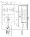
- FIG. 2depicts a lighting system that mixes colors from at least two LEDs in accordance with a correlation between phase-cut dimmer angles and a predetermined black body radiation function.
- FIG. 3depicts exemplary phase cut voltages.
- FIG. 4depicts an exemplary LED emitter.
- FIGS. 5A , 5 B, and 5 Cdepict International Commission on Illumination (CIE) diagrams with color gamuts derived from mixing at least 3 colors from at least two LED emitters.
- CIEInternational Commission on Illumination
- FIG. 6depicts an exemplary control correlated color temperature-brightness correlation profile.
- FIG. 7depicts an embodiment of the lighting system of FIG. 2 .
- FIGS. 8-11depict various configuration of LED emitters.
- a lighting systemincludes methods and systems to mix colors of light emitted from at least two LED emitters.
- the lighting systemincludes a controller that responds to phase-cut angles of the dimming signal and correlates the phase-cut angles with a predetermined black body radiation function to dynamically adjust a color spectra of the mixed light in response to changes in phase cut angles of the phase-cut dimming level signal.
- the controllerutilizes the predetermined black body radiation function to dynamically adjust the color spectra of the mixed, emitted light in response to changes in phase cut angles of a phase-cut dimming level signal.
- the predetermined black body radiation functionspecifies correlated color temperatures (CCTs) that model the CCTs of an actual non-LED based lamp, such as an incandescent lamp.
- the lighting systemincludes a controller that is configured to apply the predetermined black body radiation function to correlate the dimming level signal with at least first and second light emitting diode (“LED”) drive current levels.
- the LED emitterscollectively emit light at three or more dominant wavelengths. The resulting color gamut achievable by the lighting system incorporates all of part of the CCTs of the predetermined black body radiation function.
- the relative brightness of the LED emittersdetermines the dominant wavelength of light emitted by the mixed light of the LED emitters.
- the controllercorrelates dimming levels with the CCTs of the predetermined black body radiation function and utilizes the correlation to control LED drive currents. LED drive currents control the brightness of each LED emitters and, thus, the dominant wavelength of the lighting system.
- the controllerresponds to changes in the dimming level by adjusting the LED drive currents to maintain a correlation between the dimming level, the CCTs of the predetermined black body radiation function, and, thus, the dominant wavelength of the light emitted by the mixed light of the LED emitters.
- the dominant wavelengths of light emitted by the LED emittersdefine a color gamut of light emitted by the lighting system.
- a controller of the lighting systemcorrelates a particular dimming level with a particular CCT defined by the predetermined black body radiation function.
- the predetermined black body radiation functiondefines a curve of CCTs matching a color spectrum of an incandescent bulb from approximately no dimming to approximately fully dimmed.
- the controllervaries drive currents to the LED emitters so that the color spectra of the mixed, emitted light from the LED emitters approximately tracks the color spectrum defined by the predetermined black body radiation function in response to changes in the phase cut angles of the phase-cut dimming level signal.
- the controllerdirectly or indirectly relates the current, the dimming level in the lighting system, and the predetermined black body radiation function to control the adjustable color spectra of the lighting system.
- the controlleris programmable to specify the particular relationships between the current, the dimming level, and the predetermined black body radiation function.
- the predetermined black body radiation functionis also programmable, and programming data and the black body radiation function are stored in a non-volatile memory.
- the values of the drive currentsare pre-calculated based on the color spectra control function, dimming levels, and the predetermined black body radiation function.
- junction temperatures of one or more of the LEDs in the LED emitterscan also be factored into the color spectra control function to maintain a particular color spectra.
- the pre-calculated values of the drive currentscan be stored in a memory in a desired format, such as in a look-up-table.
- some of the drive current valuesare pre-calculated and stored in a memory, and the controller determines other drive current values using the color spectra control function.
- the color spectra or spectrum of light emitted by an LED emitteris a function of the color of light emitted by the LED emitter and any lumiphors incorporated into the LED emitter.
- a lumiphoris a structure that contains any luminescent material that generally converts exciting radiation of one wavelength to responsive radiation, such as visible light, of another wavelength. For example, many lumiphors can receive a photon of a wavelength representing a certain color of light and emit a photon of a wavelength representing a different color of light.
- Luminescent materialsinclude phosphors, scintillators, and glow tapes and inks.
- the particular lumiphors and LEDsdefine the color gamut for the lighting system.
- FIG. 2depicts a lighting system 200 that includes a LED emitter color mixing controller 202 to control the color and intensity of light 209 emitted by the LED emitter group 204 of lamp 205 by controlling LED drive currents i LDC — 1 -i LDC — N to respective LED emitters 206 . 1 - 206 .N using a black body radiation function and a dimming level indicated by the phase-cut dimming level signal DIM_LEVEL. “N” is an integer index number greater than or equal to two (2).
- the LED emitter color mixing controller 202controls the respective LED drive currents i LDC — 1 -i LDC — 3 .
- Controlling the LED drive currents i LDC — 1 -i LDC — Ncontrols the brightness of respective LED emitters 206 . 1 - 206 .N.
- controlling the brightness of the LED emitters 206 . 1 - 206 .Ncontrols the color spectra of mixed light emitted by the LED emitters 206 . 1 - 206 .N.
- the controller 210samples the phase-cut, rectified input voltage V ⁇ — R .
- Each of the N LED emitters 206 . 1 - 206 .Nincludes one or more electronic light sources, such as one or more LEDs.
- the lighting system 200receives a supply voltage V ⁇ .
- the supply voltage V ⁇is, for example, a line voltage such as V SUPPLY ( FIG. 1 ).
- the phase cut dimmer 203phase-cuts the supply voltage V ⁇ , as subsequently described in more detail, to generate the phase cut voltage version of supply voltage V ⁇ .
- the phase cut dimmer 203can be any type of phase cut dimmer, such as a triac-based dimmer or a solid state dimmer, and can be a leading edge or a trailing edge dimmer.
- Full-bridge diode rectifier 105rectifies the phase-cut supply voltage V ⁇ to generate a phase, cut rectified supply voltage V ⁇ — R .
- Switching power converter 208converts the rectified, phase-cut supply voltage V ⁇ — R into one or more, approximately constant (DC) output voltages V OUT and one or more output currents i OUT .
- the particular configuration of the LED emitters 206 . 1 - 206 .Nis a matter of design choice.
- the LED emitters 206 . 1 - 206 .Nare connected in series, and the switching power converter 208 supplies one output voltage V OUT and one output current i OUT to all the LED emitters 206 . 1 - 206 .N.
- the LED emitters 206are connected in series, and the switching power converter 208 supplies one output voltage V OUT and one output current i OUT to all the LED emitters 206 . 1 - 206 .N.
- the LED emitters 206.
- the switching power converter 208generates a separate output voltage and separate output current i OUT for each of LED emitters 206 . 1 - 206 .N.
- the particular type of switching power converter 208is a matter of design choice.
- the switching power converter 208can be a boost, buck, boost-buck, flyback, C ⁇ k type switching power converter or a combination of any of the foregoing types of switching power converters.
- the LED emitter color mixing controller 202is part of a larger controller 210 .
- the controller 210generates P switching power converter control signals CS_SPC to control generation of the output voltage V OUT and output current i OUT .
- Pis an integer greater than or equal to 1.
- U.S. Patent Application Publication 2012/0025733 entitled “Dimming Multiple Lighting Devices by Alternating Energy Transfer From a Magnetic Storage Element”, inventor John L. Melanson, assignee Cirrus Logic, Inc.(referred to herein as “Melanson I”) describes exemplary methods and systems for generating the control signals CS_SPC to control a boost-type switching power converter with a fly-back converter.
- controller 210controls the switching power converter 208 as described in, for example, U.S. patent application Ser. No. 11/967,269, entitled “Power Control System Using a Nonlinear Delta-Sigma Modulator With Nonlinear Power Conversion Process Modeling”, filed on Dec. 31, 2007, inventor John L. Melanson, U.S. patent application Ser. No. 11/967,275, entitled “Programmable Power Control System”, filed on Dec. 31, 2007, and inventor John L. Melanson, U.S. patent application Ser. No.
- controller 210including LED emitter color mixing controller 202 is a matter of design choice.
- controller 210can be implemented as an integrated circuit, discrete components, or as a combination of an integrated circuit and discrete components. Additionally, in at least one embodiment, the controller 210 utilizes software to perform some functions.
- the LED emitter color mixing controller 202determines LED drive current levels to generate LED drive currents for LED emitters 206 . 1 - 206 .N. To determine the LED drive current levels, the LED emitter color mixing controller 202 applies the predetermined black body radiation function 207 to correlate the dimming level signal DIM_LEVEL with LED drive current levels. In at least one embodiment, the predetermined black body radiation function 207 specifies CCTs for a particular dimming level value of the DIM_LEVEL signal, and the controller 202 correlates drive current levels to the CCTs of the predetermined black body radiation function 207 and the dimming level values.
- the LED emitter color mixing controller 202determines drive current levels to generate the LED drive currents i LDC — 1 to i LDC — N so that LED emitters 206 . 1 - 206 .N emit light at respective brightness levels that when mixed has a CCT approximating a CCT of the predetermined black body radiation function 207 .
- the particular predetermined black body radiation function 207is a matter of design choice.
- the predetermined black body radiation functiondefines a curve of CCTs matching a color spectrum of an incandescent bulb from approximately no dimming to approximately fully dimmed.
- the predetermined black body radiation functioncan also include several predetermined black body radiation functions that emulate various types of light sources or provide any desired color effects. Any curve or other function can be approximated using, for example, any well-known curve fitting function tool to define the curve or function as a polynomial equation. Values of the curve can also be stored in a look-up-table.
- the LED emitter color mixing controller 202generates M control signal(s) CS_ILDC to control the currents i LDC — 1 -i LDC — N .
- Mis a positive integer less than or equal to N (N is the number of LED emitters 206 . 1 through 206 .N.)
- the LED emitter color mixing controller 202also responds to the dimming level represented by the signal DIM_LEVEL by adjusting the brightness of light from LED emitter group 204 .
- the LED emitter color mixing controller 202reduces the brightness of light emitted by the LED emitters 206 .
- the LED emitter color mixing controller 202increases the brightness of light emitted by the LED emitters 206 . 1 - 206 .N by increasing one or more of LED drive currents i LDC — 1 -i LDC — N .
- the DIM_LEVEL signalcan be any signal representing a dimming level of the lighting system 200 .
- An exemplary mechanism for generating the control signal(s) CS_ILDCis described in Melanson I. Exemplary generation of the control signal(s) CS_ILDC in accordance with the value of the DIM_LEVEL signal and the black body radiation function 207 is subsequently described.
- the controller 210receives temperature data TEMP and is responsive to changes in the ambient temperature and, thus, changes to the junction temperature of the LED emitters 206 . 1 - 206 .N. Adjusting the LED drive currents i LDC — 1 -i LDC — N is described in “U.S. patent application Ser. No. 13/430,601, entitled “Color Coordination of Electronic Light Sources With Dimming and Temperature Responsiveness”, filed on Mar. 26, 2012, inventors Alfredo R. Linz, Michael A. Kost, and Sahil Singh (referred to herein as the “Linz Patent”).
- FIG. 3depicts exemplary voltage waveforms 300 of the supply voltage V ⁇ and phase cut, rectified input voltage V ⁇ — R .
- the dimmer 203phase cuts a leading edge of the supply voltage V ⁇ at a particular phase angle.
- One cycle 301 of the supply voltage V ⁇is depicted in FIG. 3 .
- the phase cut, rectified input voltage V ⁇ — Rdepicts two cycles, cycle A and cycle B, which are derived from the cycle 301 of the supply voltage V ⁇ .
- Cycle Ais a phase cut version of the first half cycle 302 of the supply voltage V ⁇
- cycle Bis a rectified, phase cut version of the second half cycle 304 of the supply voltage V ⁇
- Cycle Aoccurs from time t 0 until the zero crossing of the supply voltage V ⁇ at time t 2
- Cycle Boccurs from time t 2 until the next zero crossing at time t 4 of the supply voltage V ⁇
- the dimmer 203does not conduct current and, thus, phase cuts the supply voltage V ⁇ until time t 1 and, after time t 2 , until time t 3 .
- the dimmer 203conducts so that the phase cut, rectified input voltage V ⁇ — R equals a rectified version of the supply voltage V ⁇ .
- phase cuts at times t 1 and t 3occur at respective phase angles of the phase cut, rectified voltage V ⁇ — R .
- the phase angles or phase cut timesrepresent specific dimming levels that are used by LED emitter color mixing controller 202 to determine the color spectra of the light 209 emitted from lamp 205 .
- FIG. 4depicts a cross-sectional view of an exemplary LED emitter 400 .
- the LED emitter 400represents an exemplary embodiment LED emitters 206 . 1 - 206 .N.
- the LED emitter 400includes a lead frame 402 that supports a chip 404 .
- the wire 406connected to the chip 404 , conducts the LED drive current i LDC , the chip 404 emits photons.
- the photonsdirectly strike the lumiphor 408 or are reflected to the lumiphor 408 by reflective surface 410 .
- An encapsulate region 412forms an enclosure for the LED emitter 400 .
- Luminscent materialcan also be dispersed on the surface of the encapsulate 412 and/or embedded in the encapsulate 412 so that the encapsulate 412 also becomes a lumiphor.
- the LED emitterdoes not include the lumiphor 408 and/or does not include any significant amount of lumiscent material.
- the particular size, density, disbursement pattern, luminescent material type, color spectra of light emitted from chip 404 , etc.determine the dominant wavelength(s) of light emitted by the LED emitter 400 .
- the particular luminescent materialis a matter of design choice. Construction and design of an exemplary LED emitter 400 having one or more dominant wavelengths is, for example, described in U.S. Pat. No. 7,213,940.
- FIGS. 5A-5Cdepict International Commission on Illumination (CIE) diagrams with color gamuts derived from mixing at least 3 colors from at least two LED emitters 206 . 1 - 206 .N.
- the CIE diagrams 502 A, 502 B, and 502 Crepresent a color space created by CIE in 1931 to define the entire gamut of colors visible to the average human viewer.
- the x and y axesspecify 2-dimensional reference coordinates.
- Numbers on the perimeter of the CIE diagrams 502 A, 502 B, and 502 Crepresent wavelengths of light. Blue wavelengths are approximately 430 nm to 490 nm. Green wavelengths are about 490 nm to about 570 nm.
- the black body radiation curve 504represents the CCTs of an exemplary incandescent bulb in Kelvin over a full dimming range.
- a CCT of approximately 5000Krepresents a dimming level of approximately 100% corresponding to a phase cut angle of approximately 0-5 degrees
- a CCT of approximately 1500Krepresents a dimming level of approximately 2-10% corresponding to a phase cut angle of approximately 4-20 degrees.
- a CCT of approximately 1500Krepresents a phase cut angle of approximately 45°, as described with reference to FIG. 6 .
- the LED emitter group 204has three LED emitters 206 . 1 - 206 . 3 .
- LED emitter 206 . 1emits light with a red dominant wavelength 506 .
- LED emitter 206 . 2emits light with a yellow dominant wavelength 508
- LED emitter 206 . 3emits light using a blue LED and a lumiphor that converts some blue light to a greenish dominant wavelength 510 .
- the lines connecting dominant wavelengths 506 - 508form a triangle that defines a color gamut 512 .
- the lamp 205can emit a light color 209 anywhere within the color gamut 512 .
- the LED emitter color mixing controller 202adjusts the brightness of LED emitters 206 . 1 - 206 . 3 .
- the black body radiation curve 504 of an incandescent bulblies within the color gamut 512 from 1500K-5000K.
- the LED emitter color mixing controller 202can cause the light 209 to have a color spectra anywhere along the black body radiation curve 504 of an incandescent bulb from 1500K-5000K. Determining the values of the respective LED drive currents i LDC — 1 -i LDC — 3 that correspond to CCTs on along the black body radiation curve 504 is a matter of design choice and can be done empirically or by calculation using response characteristics of the LED emitters 206 . 1 - 206 . 3 .
- the efficacy of each of LED emitters 206 . 1 - 206 .Nis calibrated by providing the programming & calibration data to the LED emitter color mixing controller 202 as, for example, described in U.S. Patent Application No. 2010/0277072, inventors William Draper, Robert Grisamore, and John Melanson, and assignee Cirrus Logic, Inc., which is incorporated by reference in its entirety. “Efficacy” is defined herein as the light output of an LED emitter 206 divided by the total electrical power input to the light source, expressed in lumens per watt (lm/W).
- a phase cut anglecorresponds to a particular dimming value of the DIM_LEVEL signal, and the dimming values correlate with respective CCTs along the black body radiation curve 504 .
- the particular correspondenceis a matter of design choice with an example correlation shown in FIG. 6 , which is discussed below.
- the LED emitter color mixing controller 202controls the respective LED drive currents i LDC — 1 -i LDC — 3 so that the light 209 has a dominant wavelength that at least approximates the CCT of the incandescent bulb when dimmed.
- the manner of applying the CCTs of the black body radiation curve 504 to correlate the dimming levels from the phase cut dimmer 203 to LED drive current levels for the respective LED drive currents i LDC — 1 -i LDC — 3is a matter of design choice.
- the dominant wavelength of each of LED emitters 206 . 1 through 206 .Nis known or stored as a value in the LED emitter color mixing controller 202 or is received as data from a color sensor (not shown). Any method including well-known methods can be used to determine a function that specifies the spectra of the mixed light from the LED emitters 206 . 1 through 206 .N as a function of the drive current to LED emitters 206 .
- the LED emitter color mixing controller 202can apply the black body radiation function to correlate the dimming level signal with at least first and second light emitting diode (“LED”) drive current levels to control the drive currents to the LED emitters 206 . 1 through 206 .N.
- LEDlight emitting diode
- the LED emitter color mixing controller 202responds to changes in the corresponding dimming level signal DIM_LEVEL by applying predetermined black body radiation function to re-correlate the dimming level signal DIM_LEVEL with revised current level values of LED drive currents i LDC — 1 -i LDC — 3 .
- the black body radiation curve 504represents one example of a predetermined black body radiation function 207 .
- FIG. 5Butilizes two LED emitters 206 . 1 and 206 . 2 .
- the LED emitter 206 . 1includes a blue LED and lumiphors that shift the color of the blue LED to the dominant wavelengths 520 and 522 .
- the LED emitter 206 . 2includes a red LED with a dominant wavelength 524 , which established a color gamut within triangle 526 .
- the LED emitter color mixing controller 202controls the respective LED drive currents i LDC — 1 -i LDC — 3 so that the light 209 has a dominant wavelength that at least approximates the CCT of the incandescent bulb when dimmed.
- FIG. 5Cutilizes three LED emitters 206 . 1 - 206 . 3 .
- the LED emitter 206 . 1includes a blue LED with dominant wavelength 530 and lumiphors that shift the color of the blue LED to the green dominant wavelength 532 .
- the LED emitter 206 . 1also includes a red LED, which has a dominant wavelength 534 .
- the LED emitter color mixing controller 202can generate an LED drive current i LDC — 1 to cause the LED emitter 206 . 1 to emit light at a dominant wavelength 538 .
- the LED emitter 206.
- the LED emitter color mixing controller 202controls the respective LED drive currents i LDC — 1 -i LDC — 2 so that the light 209 has a dominant wavelength that at least approximates the CCT of the incandescent bulb when dimmed.
- the number of LEDs within each LED emitter 206and the number of LED emitters 206 . 1 - 206 .N is a matter of design choice.
- the colors and color shifting using, for example, lumiphors, of the LED emitters 206 . 1 - 206 .Nis also a matter of design choice.
- the choice of the number of LEDs within each LED emitter 206the number of LED emitters 206 .
- the colors of lightdepend on a number of variables, such as the level of brightness desired, the particular black body radiation function to be applied by the LED emitter color mixing controller 202 , the degree of accuracy desired between the actual CCT of the light 209 and the CCT of the particular, applied black body radiation function, and the cost of the LED emitters 206 . 1 - 206 .N and the LED emitter color mixing controller 202 .
- FIG. 6depicts an exemplary control CCT-brightness correlation profile 600 for use by LED emitter color mixing controller 202 to control the color and intensity of light 209 based on the dimmer level represented by the DIM_LEVEL signal.
- the LED emitter color mixing controller 202At low phase angles, the LED emitter color mixing controller 202 generates the LED drive currents i LDC — 1 -i LDC — N so that the lamp 205 generates light 209 with a CCT of 4500K at a maximum brightness.
- the LED emitter color mixing controller 202As the phase angle cut increases, the LED emitter color mixing controller 202 generates the LED drive currents i LDC — 1 -i LDC — N so that the lamp 205 generates light 209 with a CCT decreasing from 4500K to 1500K while maintaining maximum brightness. As the phase angle cut continues to increase, the LED emitter color mixing controller 202 generates the LED drive currents i LDC — 1 -i N so that the CCT remains at 1500K while the brightness is decreased.
- the control CCT-brightness correlation profile 600can be used to allow the lighting system 200 to replace an incandescent bulb while providing a bright reading mode for all levels of CCTs.
- the particular control CCT-brightness correlation profileis a matter of design choice.
- FIG. 7depicts lighting system 700 , which represents one embodiment of lighting system 200 .
- Controller 701represents one embodiment of controller 210
- LED emitter color mixing controller 702represents one embodiment of LED emitter color mixing controller 202 .
- Lamp 705represents one embodiment of lamp 205 ( FIG. 2 ).
- the LED emitter color mixing controller 702includes a processor 712 to generate the M number of LED control signals CS_ILDC to control the LED drive currents i LDC — 1 -i LDC — N .
- Capacitors 708 . 1 - 708 .Neach provides a standard filter across respective LED emitters 704 . 1 and 704 .N.
- the dimming level detector 720detects the phase cut angle or phase cut time from the phase cut, rectified input voltage V ⁇ — R and provides the dimming level signal DIM_LEVEL to processor 712 .
- Exemplary dimming level detectorsare described in U.S. patent application Ser. No. 13/290,032, entitled “Switching Power Converter Input Voltage Approximate Zero Crossing Determination”, filed on Nov. 4, 2011, inventors Eric J. King, John L. Melanson, which is incorporated by reference in its entirety.
- the processor 712utilizes the temperature of the LED group 714 , the dimming level of the lighting system 700 as represented by the respective TEMP and DIM_LEVEL signals, and the black body radiation function 207 stored in memory 722 to generate the control signals CS_ILDC to control the LED drive currents i LDC — 1 -i LDC — N .
- the predetermined black body radiation functionis represented by a map that correlates dimming level signal DIM_LEVEL values to the levels for the LED drive currents i LDC — 1 -i LDC — N .
- the memory 722stores the map, and the processor 712 retrieves data from the map in the memory 722 that corresponds to the dimming level signal DIM_LEVEL values to generate light from LED emitters 704 . 1 - 704 .N having CCTs that tracks the dimming signal level and the predetermined black body radiation function 207 .
- the predetermined black body radiation function 207is represented by an algorithm stored in the memory 722 .
- the processor 712calculates the LED drive currents i LDC — 1 -i LDC — N levels to cause the LED emitters 704 . 1 - 704 .N to generate light having CCTs that track the dimming signal level and the predetermined black body radiation function 207 .
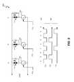
- FIGS. 8-11depict various configuration of LED emitters, which represent embodiments of LED emitters 206 . 1 - 206 .N.
- Each of the LED emitters in FIGS. 8-11is shown for illustrative purposes having two LEDs and illustrative control signal pulses. However, the number of LEDs in each LED emitter is a matter of design choice and can be one, two, or any desired number.
- the LED emitter group 800includes LED emitters A, B, and C arranged in parallel. The voltage and, thus, the drive current i LDC — A is held constant by Zener diode 802 .
- Respective LED drive currents i LDC — B and i LDC — C to LED emitters B and Care controlled by respective switches 804 and 806 .
- switches 804 and 806are field effect transistors (FETs) with conductivity controlled by respective control signals CS B and CS C .
- Control signals CS B and CS Crepresent one embodiment of control signals CS_ILDC ( FIGS. 2 and 7 ).
- control signals CS B and CS Care pulse width modulated signals, and the duty cycle of control signals CS B and CS C is directly proportional to the brightness of respective LED emitters B and C.
- LED emitters A, B, and Chave a color spectrum that defines a color gamut as described with reference to FIGS.
- B ATT ⁇ R TT ⁇ R + TT ⁇ B + TT ⁇ C
- B Ais the contribution brightness of LED emitter A to light 209
- TTis the duration of each pulse of control signals CS B and CS C
- Ris the total number of pulses of control signals CS B and CS C of a desired series of pulses
- Bis the number of pulses of control signal CS B
- Cis the number of pulses of control signal CS C .
- FIG. 9depicts the LED emitter group 900 with LED emitters A, B, and C arranged in parallel.
- Respective LED drive currents i LDC — A , i LDC — B and i LDC — C to LED emitters A, B, and Care controlled by respective switches 902 , 804 and 806 .
- switch 902is also a FET and has conductivity controlled by control signals CS A .
- Control signals CS A , CS B , and CS Crepresent one embodiment of control signals CS_ILDC ( FIGS. 2 and 7 ).
- control signal CS Ais also a pulse width modulated signal, and the duty cycle of control signals CS A is directly proportional to the brightness of LED emitter A.
- LED emitters A, B, and Chave a color spectrum that defines a color gamut as described with reference to FIGS. 5A , 5 B, and 5 C.
- Control signals CS A , CS B , and CS Ccontrol the respective brightness of LED emitters A, B, and C, and, thus, the control signals CS A , CS B , and CS C control the CCT of the light 209 emitted by the mixture of light emitted from LED emitters A, B, and C.
- Exemplary pulse width signals 904generate the combinations 906 of color mixing.
- the contribution of brightness of LED emitter A to light 209 ( FIG. 2 ) relative to the contribution of brightness of LED emitters B and C for a series of R pulses and each pulse having a duration of TTis:
- B ATT ⁇ A TT ⁇ A + TT ⁇ B + TT ⁇ C
- B Ais the contribution brightness of LED emitter A to light 209
- TTis the duration of each pulse of control signals CS B and CS C
- Bis the number of pulses of control signal CS B
- Cis the number of pulses of control signal CS C .
- FIG. 10depicts the LED emitter group 900 with LED emitters A, B, and C arranged in series.
- LED emitters A, B, and Chave a color spectrum that defines a color gamut as described with reference to FIGS. 5A , 5 B, and 5 C.
- Exemplary pulse width signals 1004generate the combinations 1004 of color mixing.
- FIG. 11depicts two LED emitter groups 1102 and 1104 , each group having two LED emitters A and B.
- the operation of LED group 1102is the same as LED group 800 except that LED group 1102 has two strings of LED emitters rather than three.
- the operation of LED group 1104is the same as LED group 900 except that LED group 1104 has two strings of LED emitters rather than three.
- LED groups 1102 and 1104facilitate, for example, obtaining the color gamut 526 ( FIG. 5B ) and correlation between the dimming levels of the phase cut dimmer 203 with the black body radiation curve 504 .
- Melanson Idescribes the mechanism for generating the combinations of pulses of control signals CS A , CS B , and CS C .
- the LED emitter color mixing controllers 202 and 702generate the control signals CS A , CS B , and CS C to apply a predetermined black body radiation function to correlate the dimming level signal DIM_LEVEL with LED drive current levels so that the color spectrum of mixed, emitted light from respective lighting systems 200 and 700 approximates a color spectrum of the predetermined black body radiation function for each value of the dimming level signal DIM_LEVEL.
- a controller of a lighting systemreceives a phase-cut dimming level signal and controls mixing of colors of light emitted from at least two LED emitters by utilizing a predetermined black body radiation function to dynamically adjust a color spectra (i.e. dominant wavelength) of the light in response to changes in phase cut angles of the phase-cut dimming level signal.
Landscapes
- Circuit Arrangement For Electric Light Sources In General (AREA)
Abstract
Description
wherein BAis the contribution brightness of LED emitter A to
wherein BAis the contribution brightness of LED emitter A to
Claims (37)
Priority Applications (3)
| Application Number | Priority Date | Filing Date | Title |
|---|---|---|---|
| PCT/US2012/064543WO2013071181A2 (en) | 2011-11-11 | 2012-11-09 | Color mixing of electronic light sources with correlation between phase-cut dimmer angle and predetermined black body radiation function |
| US13/673,879US8912734B2 (en) | 2011-03-24 | 2012-11-09 | Color mixing of electronic light sources with correlation between phase-cut dimmer angle and predetermined black body radiation function |
| CN201280052122.4ACN103891406B (en) | 2011-11-11 | 2012-11-09 | Using the blend of colors of the electron light source of the correlation between phase-cut dimmer angle and predetermined black body function |
Applications Claiming Priority (6)
| Application Number | Priority Date | Filing Date | Title |
|---|---|---|---|
| US201161467258P | 2011-03-24 | 2011-03-24 | |
| US201161532980P | 2011-09-09 | 2011-09-09 | |
| US201161558529P | 2011-11-11 | 2011-11-11 | |
| US201261600330P | 2012-02-17 | 2012-02-17 | |
| US13/430,601US8823289B2 (en) | 2011-03-24 | 2012-03-26 | Color coordination of electronic light sources with dimming and temperature responsiveness |
| US13/673,879US8912734B2 (en) | 2011-03-24 | 2012-11-09 | Color mixing of electronic light sources with correlation between phase-cut dimmer angle and predetermined black body radiation function |
Related Parent Applications (1)
| Application Number | Title | Priority Date | Filing Date |
|---|---|---|---|
| US13/430,601Continuation-In-PartUS8823289B2 (en) | 2011-03-24 | 2012-03-26 | Color coordination of electronic light sources with dimming and temperature responsiveness |
Publications (2)
| Publication Number | Publication Date |
|---|---|
| US20130069561A1 US20130069561A1 (en) | 2013-03-21 |
| US8912734B2true US8912734B2 (en) | 2014-12-16 |
Family
ID=48290774
Family Applications (1)
| Application Number | Title | Priority Date | Filing Date |
|---|---|---|---|
| US13/673,879Active2032-04-10US8912734B2 (en) | 2011-03-24 | 2012-11-09 | Color mixing of electronic light sources with correlation between phase-cut dimmer angle and predetermined black body radiation function |
Country Status (3)
| Country | Link |
|---|---|
| US (1) | US8912734B2 (en) |
| CN (1) | CN103891406B (en) |
| WO (1) | WO2013071181A2 (en) |
Cited By (11)
| Publication number | Priority date | Publication date | Assignee | Title |
|---|---|---|---|---|
| US20150289335A1 (en)* | 2014-04-04 | 2015-10-08 | Lumenpulse Lighting Inc. | System and method for powering and controlling a solid state lighting unit |
| US9320097B2 (en) | 2013-05-10 | 2016-04-19 | Marvell World Trade Ltd. | Multi-string dimmable LED driver |
| US9693421B2 (en) | 2015-06-24 | 2017-06-27 | Industrial Technology Research Institute | Lighting apparatus of adjustable color temperature and a method for adjusting color temperature thereof |
| US9907132B2 (en) | 2015-10-29 | 2018-02-27 | Abl Ip Holding Llc | Lighting control system for independent adjustment of color and intensity |
| US10159131B1 (en)* | 2018-03-26 | 2018-12-18 | Adam Chaimberg | Dimmable LED light fixture maintaining brightness during color temperature change |
| US10306724B2 (en) | 2017-01-15 | 2019-05-28 | Ecosense Lighting Inc. | Lighting systems, and systems for determining periodic values of a phase angle of a waveform power input |
| US10321532B2 (en) | 2016-03-29 | 2019-06-11 | Azoteq (Pty) Ltd | Power factor dimming |
| US10477636B1 (en) | 2014-10-28 | 2019-11-12 | Ecosense Lighting Inc. | Lighting systems having multiple light sources |
| US10483850B1 (en) | 2017-09-18 | 2019-11-19 | Ecosense Lighting Inc. | Universal input-voltage-compatible switched-mode power supply |
| US10874006B1 (en) | 2019-03-08 | 2020-12-22 | Abl Ip Holding Llc | Lighting fixture controller for controlling color temperature and intensity |
| US11778715B2 (en) | 2020-12-23 | 2023-10-03 | Lmpg Inc. | Apparatus and method for powerline communication control of electrical devices |
Families Citing this family (45)
| Publication number | Priority date | Publication date | Assignee | Title |
|---|---|---|---|---|
| US8476836B2 (en) | 2010-05-07 | 2013-07-02 | Cree, Inc. | AC driven solid state lighting apparatus with LED string including switched segments |
| US10178723B2 (en) | 2011-06-03 | 2019-01-08 | Cree, Inc. | Systems and methods for controlling solid state lighting devices and lighting apparatus incorporating such systems and/or methods |
| US9839083B2 (en) | 2011-06-03 | 2017-12-05 | Cree, Inc. | Solid state lighting apparatus and circuits including LED segments configured for targeted spectral power distribution and methods of operating the same |
| WO2014099681A2 (en) | 2012-12-17 | 2014-06-26 | Ecosense Lighting Inc. | Systems and methods for dimming of a light source |
| US10231300B2 (en) | 2013-01-15 | 2019-03-12 | Cree, Inc. | Systems and methods for controlling solid state lighting during dimming and lighting apparatus incorporating such systems and/or methods |
| US10264638B2 (en) | 2013-01-15 | 2019-04-16 | Cree, Inc. | Circuits and methods for controlling solid state lighting |
| US9565782B2 (en) | 2013-02-15 | 2017-02-07 | Ecosense Lighting Inc. | Field replaceable power supply cartridge |
| US9282597B2 (en)* | 2013-04-02 | 2016-03-08 | Magnitude Holdings Ltd., A Bermuda Exempt Company Limited By Shares | Device and method for controlled LED lighting |
| DE102013210581B4 (en)* | 2013-06-06 | 2015-01-08 | Osram Gmbh | Circuit arrangement and method for operating and dimming at least one LED |
| WO2015085050A1 (en)* | 2013-12-06 | 2015-06-11 | Cree, Inc. | Leds configured for targeted spectral power disbution |
| RU2015145160A (en) | 2014-01-21 | 2017-04-25 | Филипс Лайтинг Холдинг Б.В. | LIGHTING SYSTEM AND METHOD FOR MANAGING A LIGHTING SYSTEM |
| US9214862B2 (en)* | 2014-04-17 | 2015-12-15 | Philips International, B.V. | Systems and methods for valley switching in a switching power converter |
| US9593812B2 (en) | 2014-04-23 | 2017-03-14 | Cree, Inc. | High CRI solid state lighting devices with enhanced vividness |
| DE102014115076A1 (en)* | 2014-10-16 | 2016-04-21 | "Durable" Hunke & Jochheim Gmbh & Co. Kommanditgesellschaft | Method for controlling an LED light and LED light |
| US9301361B1 (en)* | 2014-11-05 | 2016-03-29 | Cooper Technologies Company | Dimming interface module |
| US9702524B2 (en) | 2015-01-27 | 2017-07-11 | Cree, Inc. | High color-saturation lighting devices |
| US11306897B2 (en) | 2015-02-09 | 2022-04-19 | Ecosense Lighting Inc. | Lighting systems generating partially-collimated light emissions |
| US9869450B2 (en) | 2015-02-09 | 2018-01-16 | Ecosense Lighting Inc. | Lighting systems having a truncated parabolic- or hyperbolic-conical light reflector, or a total internal reflection lens; and having another light reflector |
| US9651227B2 (en) | 2015-03-03 | 2017-05-16 | Ecosense Lighting Inc. | Low-profile lighting system having pivotable lighting enclosure |
| US9568665B2 (en) | 2015-03-03 | 2017-02-14 | Ecosense Lighting Inc. | Lighting systems including lens modules for selectable light distribution |
| US9746159B1 (en) | 2015-03-03 | 2017-08-29 | Ecosense Lighting Inc. | Lighting system having a sealing system |
| US9651216B2 (en) | 2015-03-03 | 2017-05-16 | Ecosense Lighting Inc. | Lighting systems including asymmetric lens modules for selectable light distribution |
| CN104936353B (en)* | 2015-06-26 | 2017-06-06 | 复旦大学 | It is a kind of to realize the method that different spectrum are exported by changing LED peak wavelengths |
| USD785218S1 (en) | 2015-07-06 | 2017-04-25 | Ecosense Lighting Inc. | LED luminaire having a mounting system |
| US9451666B1 (en) | 2015-07-08 | 2016-09-20 | Cooper Technologies Company | Adjustable lighting driver |
| US9504112B1 (en)* | 2015-07-08 | 2016-11-22 | Cooper Technologies Company | Adaptive lighting driver |
| USD782093S1 (en) | 2015-07-20 | 2017-03-21 | Ecosense Lighting Inc. | LED luminaire having a mounting system |
| USD782094S1 (en) | 2015-07-20 | 2017-03-21 | Ecosense Lighting Inc. | LED luminaire having a mounting system |
| US9668307B2 (en) | 2015-07-27 | 2017-05-30 | GE Lighting Solutions, LLC | Warm dimming for an LED light source |
| US9651232B1 (en) | 2015-08-03 | 2017-05-16 | Ecosense Lighting Inc. | Lighting system having a mounting device |
| JP6631913B2 (en)* | 2016-01-21 | 2020-01-15 | パナソニックIpマネジメント株式会社 | lighting equipment |
| CN105873269B (en)* | 2016-03-31 | 2018-05-08 | 深圳市九洲光电科技有限公司 | A kind of method and system of compatible silicon controlled light modulation |
| CN105657914B (en)* | 2016-03-31 | 2018-06-29 | 深圳市九洲光电科技有限公司 | The adjusting control circuit and method of a kind of adjustable color temperature |
| WO2017190986A1 (en)* | 2016-05-03 | 2017-11-09 | Philips Lighting Holding B.V. | Dimming controller. |
| CN106332364A (en)* | 2016-10-01 | 2017-01-11 | 普天智能照明研究院有限公司 | Device for adjusting color temperature through thyristor dimming power source |
| US10560993B1 (en)* | 2018-03-08 | 2020-02-11 | Universal Lighting Technologies, Inc. | Dimming controller for LED driver and method of indirect power estimation |
| CN109640459B (en)* | 2019-01-29 | 2021-01-19 | 无锡奥利杰科技有限公司 | Switch color temperature adjusting control circuit based on LED illumination linear driving condition |
| US11252794B2 (en) | 2019-03-29 | 2022-02-15 | Electronic Theatre Controls, Inc. | Systems, devices, and methods for controlling an LED light source based on a color temperature scale factor |
| GB2584772B (en)* | 2019-03-29 | 2022-10-12 | Electronic Theatre Controls Inc | Systems, devices, and methods for controlling an LED light source based on a color temperature scale factor |
| CN112804797B (en)* | 2019-10-28 | 2024-02-09 | 松下知识产权经营株式会社 | Lighting device and lighting system having the lighting device |
| CN115517019A (en)* | 2020-03-31 | 2022-12-23 | 路创技术有限责任公司 | Color temperature control of lighting fixtures |
| WO2021249975A1 (en)* | 2020-06-09 | 2021-12-16 | Signify Holding B.V. | A method of controlling a lighting emitting diode lighting device and a light emitting diode, led, based lighting device |
| CN216087069U (en)* | 2020-11-30 | 2022-03-18 | 赛万特科技有限责任公司 | Lighting device and filament device |
| CN113873212B (en)* | 2021-12-02 | 2022-03-08 | 深圳市爱图仕影像器材有限公司 | Light combination method, intelligent terminal and storage medium |
| CN116107371B (en)* | 2022-11-25 | 2024-06-18 | 深圳市美矽微半导体股份有限公司 | Stable current generation method and circuit |
Citations (67)
| Publication number | Priority date | Publication date | Assignee | Title |
|---|---|---|---|---|
| US4409476A (en) | 1980-06-16 | 1983-10-11 | Asea Aktiebolag | Fiber optic temperature-measuring apparatus |
| US6016038A (en) | 1997-08-26 | 2000-01-18 | Color Kinetics, Inc. | Multicolored LED lighting method and apparatus |
| US6150744A (en) | 1999-08-13 | 2000-11-21 | Brite Star Limited | Sealed type motor arrangement |
| US6211626B1 (en) | 1997-08-26 | 2001-04-03 | Color Kinetics, Incorporated | Illumination components |
| US6211620B1 (en) | 1998-09-24 | 2001-04-03 | Matsushita Electric Industrial Co., Ltd. | Ballast for fluorescent lamp |
| US6369525B1 (en) | 2000-11-21 | 2002-04-09 | Philips Electronics North America | White light-emitting-diode lamp driver based on multiple output converter with output current mode control |
| US6441558B1 (en) | 2000-12-07 | 2002-08-27 | Koninklijke Philips Electronics N.V. | White LED luminary light control system |
| US20020145041A1 (en) | 2001-03-16 | 2002-10-10 | Koninklijke Philips Electronics N.V. | RGB LED based light driver using microprocessor controlled AC distributed power system |
| WO2002091805A2 (en) | 2001-05-10 | 2002-11-14 | Color Kinetics Incorporated | Systems and methods for synchronizing lighting effects |
| US6495964B1 (en) | 1998-12-18 | 2002-12-17 | Koninklijke Philips Electronics N.V. | LED luminaire with electrically adjusted color balance using photodetector |
| US20030057886A1 (en) | 1997-08-26 | 2003-03-27 | Lys Ihor A. | Methods and apparatus for controlling devices in a networked lighting system |
| US20030085749A1 (en) | 2000-02-03 | 2003-05-08 | Koninklijke Philips Electronics N.V. | Supply assembly for a led lighting module |
| US6583550B2 (en) | 2000-10-24 | 2003-06-24 | Toyoda Gosei Co., Ltd. | Fluorescent tube with light emitting diodes |
| US6636003B2 (en) | 2000-09-06 | 2003-10-21 | Spectrum Kinetics | Apparatus and method for adjusting the color temperature of white semiconduct or light emitters |
| US6688753B2 (en) | 2001-02-02 | 2004-02-10 | Koninklijke Philips Electronics N.V. | Integrated light source |
| US20040085030A1 (en) | 2002-10-30 | 2004-05-06 | Benoit Laflamme | Multicolor lamp system |
| US20040105261A1 (en) | 1997-12-17 | 2004-06-03 | Color Kinetics, Incorporated | Methods and apparatus for generating and modulating illumination conditions |
| US6753661B2 (en) | 2002-06-17 | 2004-06-22 | Koninklijke Philips Electronics N.V. | LED-based white-light backlighting for electronic displays |
| US6756772B2 (en) | 2002-07-08 | 2004-06-29 | Cogency Semiconductor Inc. | Dual-output direct current voltage converter |
| US20040169477A1 (en) | 2003-02-28 | 2004-09-02 | Naoki Yanai | Dimming-control lighting apparatus for incandescent electric lamp |
| US6788011B2 (en) | 1997-08-26 | 2004-09-07 | Color Kinetics, Incorporated | Multicolored LED lighting method and apparatus |
| US20040212321A1 (en) | 2001-03-13 | 2004-10-28 | Lys Ihor A | Methods and apparatus for providing power to lighting devices |
| US6888322B2 (en) | 1997-08-26 | 2005-05-03 | Color Kinetics Incorporated | Systems and methods for color changing device and enclosure |
| EP1528785A1 (en) | 2003-10-14 | 2005-05-04 | Archimede Elettronica S.r.l. | Device and method for controlling the color of a light source |
| US20050218838A1 (en) | 2004-03-15 | 2005-10-06 | Color Kinetics Incorporated | LED-based lighting network power control methods and apparatus |
| US20050231459A1 (en) | 2004-04-20 | 2005-10-20 | Sony Corporation | Constant current driving device, backlight light source device, and color liquid crystal display device |
| US6958920B2 (en) | 2003-10-02 | 2005-10-25 | Supertex, Inc. | Switching power converter and method of controlling output voltage thereof using predictive sensing of magnetic flux |
| US20050243022A1 (en) | 2004-04-30 | 2005-11-03 | Arques Technology, Inc. | Method and IC driver for series connected R, G, B LEDs |
| US20050253533A1 (en)* | 2002-05-09 | 2005-11-17 | Color Kinetics Incorporated | Dimmable LED-based MR16 lighting apparatus methods |
| US6967448B2 (en) | 1997-08-26 | 2005-11-22 | Color Kinetics, Incorporated | Methods and apparatus for controlling illumination |
| US6975079B2 (en) | 1997-08-26 | 2005-12-13 | Color Kinetics Incorporated | Systems and methods for controlling illumination sources |
| US20060023002A1 (en) | 2004-08-02 | 2006-02-02 | Oki Electric Industry Co., Ltd. | Color balancing circuit for a display panel |
| US20060125420A1 (en) | 2004-12-06 | 2006-06-15 | Michael Boone | Candle emulation device |
| US7064498B2 (en) | 1997-08-26 | 2006-06-20 | Color Kinetics Incorporated | Light-emitting diode based products |
| WO2006067521A1 (en) | 2004-12-20 | 2006-06-29 | Outside In (Cambridge) Limited | Lightning apparatus and method |
| US7079791B2 (en) | 2003-09-02 | 2006-07-18 | Lite-On Technology Corporation | Apparatus for reducing warm-up time by auxiliary light source and method for the same |
| US7088059B2 (en) | 2004-07-21 | 2006-08-08 | Boca Flasher | Modulated control circuit and method for current-limited dimming and color mixing of display and illumination systems |
| US7116294B2 (en) | 2003-02-07 | 2006-10-03 | Whelen Engineering Company, Inc. | LED driver circuits |
| US20060226795A1 (en) | 2005-04-08 | 2006-10-12 | S.C. Johnson & Son, Inc. | Lighting device having a circuit including a plurality of light emitting diodes, and methods of controlling and calibrating lighting devices |
| US20060232219A1 (en) | 2003-05-07 | 2006-10-19 | Koninklijke Philips Electronics N.V. | Single driver for multiple light emitting diodes |
| US20070029946A1 (en) | 2005-08-03 | 2007-02-08 | Yu Chung-Che | APPARATUS OF LIGHT SOURCE AND ADJUSTABLE CONTROL CIRCUIT FOR LEDs |
| WO2007026170A2 (en) | 2005-09-03 | 2007-03-08 | E-Light Limited | Improvements to lighting systems |
| US7213940B1 (en) | 2005-12-21 | 2007-05-08 | Led Lighting Fixtures, Inc. | Lighting device and lighting method |
| US20070126656A1 (en) | 2005-12-07 | 2007-06-07 | Industrial Technology Research Institute | Illumination brightness and color control system and method therefor |
| US7246919B2 (en) | 2004-03-03 | 2007-07-24 | S.C. Johnson & Son, Inc. | LED light bulb with active ingredient emission |
| WO2007093938A1 (en) | 2006-02-14 | 2007-08-23 | Koninklijke Philips Electronics N.V. | Current driving of leds |
| US20070195526A1 (en) | 1997-08-26 | 2007-08-23 | Color Kinetics Incorporated | Wireless lighting control methods and apparatus |
| US20070211013A1 (en) | 2006-03-03 | 2007-09-13 | Nec Corporation | Light source apparatus, display apparatus, terminal apparatus, and control method thereof |
| US7288902B1 (en) | 2007-03-12 | 2007-10-30 | Cirrus Logic, Inc. | Color variations in a dimmable lighting device with stable color temperature light sources |
| US20070262724A1 (en) | 2006-05-15 | 2007-11-15 | Alexander Mednik | Shunting type pwm dimming circuit for individually controlling brightness of series connected leds operated at constant current and method therefor |
| US20080018261A1 (en) | 2006-05-01 | 2008-01-24 | Kastner Mark A | LED power supply with options for dimming |
| US20080054815A1 (en) | 2006-09-01 | 2008-03-06 | Broadcom Corporation | Single inductor serial-parallel LED driver |
| US20080116818A1 (en) | 2006-11-21 | 2008-05-22 | Exclara Inc. | Time division modulation with average current regulation for independent control of arrays of light emitting diodes |
| WO2008072160A1 (en) | 2006-12-13 | 2008-06-19 | Koninklijke Philips Electronics N.V. | Method for light emitting diode control and corresponding light sensor array, backlight and liquid crystal display |
| US20080150433A1 (en) | 2006-12-26 | 2008-06-26 | Kabushiki Kaisha Toshiba | Backlight control unit and backlight control method |
| US20080224631A1 (en) | 2007-03-12 | 2008-09-18 | Melanson John L | Color variations in a dimmable lighting device with stable color temperature light sources |
| US7498753B2 (en) | 2006-12-30 | 2009-03-03 | The Boeing Company | Color-compensating Fluorescent-LED hybrid lighting |
| US7511437B2 (en) | 2006-02-10 | 2009-03-31 | Philips Solid-State Lighting Solutions, Inc. | Methods and apparatus for high power factor controlled power delivery using a single switching stage per load |
| US20090184616A1 (en) | 2007-10-10 | 2009-07-23 | Cree Led Lighting Solutions, Inc. | Lighting device and method of making |
| US20090218960A1 (en) | 2007-03-13 | 2009-09-03 | Renaissance Lighting, Inc. | Step-wise intensity control of a solid state lighting system |
| US7649326B2 (en) | 2006-03-27 | 2010-01-19 | Texas Instruments Incorporated | Highly efficient series string LED driver with individual LED control |
| WO2010016002A1 (en) | 2008-08-06 | 2010-02-11 | Nxp B.V. | Dimming lighting devices |
| US7804478B2 (en) | 2003-04-25 | 2010-09-28 | Thales | Feedback control device for photo-colorimetric parameters for a light box with color LEDs |
| US20110001440A1 (en)* | 2008-02-06 | 2011-01-06 | Nxp B.V. | Light color tunability |
| WO2011048214A1 (en) | 2009-10-23 | 2011-04-28 | Tridonic Gmbh & Co Kg | Operation of an led luminaire having a variable spectrum |
| WO2011061505A1 (en) | 2009-11-20 | 2011-05-26 | Technelec Ltd | Led power supply |
| US20120146519A1 (en)* | 2010-12-13 | 2012-06-14 | Arkalumen Inc. | Lighting apparatus and circuits for lighting apparatus |
Family Cites Families (3)
| Publication number | Priority date | Publication date | Assignee | Title |
|---|---|---|---|---|
| US8203260B2 (en)* | 2007-04-13 | 2012-06-19 | Intematix Corporation | Color temperature tunable white light source |
| US8482223B2 (en) | 2009-04-30 | 2013-07-09 | Cirrus Logic, Inc. | Calibration of lamps |
| US8729811B2 (en) | 2010-07-30 | 2014-05-20 | Cirrus Logic, Inc. | Dimming multiple lighting devices by alternating energy transfer from a magnetic storage element |
- 2012
- 2012-11-09USUS13/673,879patent/US8912734B2/enactiveActive
- 2012-11-09WOPCT/US2012/064543patent/WO2013071181A2/enactiveApplication Filing
- 2012-11-09CNCN201280052122.4Apatent/CN103891406B/enactiveActive
Patent Citations (73)
| Publication number | Priority date | Publication date | Assignee | Title |
|---|---|---|---|---|
| US4409476A (en) | 1980-06-16 | 1983-10-11 | Asea Aktiebolag | Fiber optic temperature-measuring apparatus |
| US6788011B2 (en) | 1997-08-26 | 2004-09-07 | Color Kinetics, Incorporated | Multicolored LED lighting method and apparatus |
| US6975079B2 (en) | 1997-08-26 | 2005-12-13 | Color Kinetics Incorporated | Systems and methods for controlling illumination sources |
| US6211626B1 (en) | 1997-08-26 | 2001-04-03 | Color Kinetics, Incorporated | Illumination components |
| US6888322B2 (en) | 1997-08-26 | 2005-05-03 | Color Kinetics Incorporated | Systems and methods for color changing device and enclosure |
| US7135824B2 (en) | 1997-08-26 | 2006-11-14 | Color Kinetics Incorporated | Systems and methods for controlling illumination sources |
| US6967448B2 (en) | 1997-08-26 | 2005-11-22 | Color Kinetics, Incorporated | Methods and apparatus for controlling illumination |
| US6016038A (en) | 1997-08-26 | 2000-01-18 | Color Kinetics, Inc. | Multicolored LED lighting method and apparatus |
| US20070195526A1 (en) | 1997-08-26 | 2007-08-23 | Color Kinetics Incorporated | Wireless lighting control methods and apparatus |
| US7064498B2 (en) | 1997-08-26 | 2006-06-20 | Color Kinetics Incorporated | Light-emitting diode based products |
| US20030057886A1 (en) | 1997-08-26 | 2003-03-27 | Lys Ihor A. | Methods and apparatus for controlling devices in a networked lighting system |
| US20040105261A1 (en) | 1997-12-17 | 2004-06-03 | Color Kinetics, Incorporated | Methods and apparatus for generating and modulating illumination conditions |
| US6211620B1 (en) | 1998-09-24 | 2001-04-03 | Matsushita Electric Industrial Co., Ltd. | Ballast for fluorescent lamp |
| US6495964B1 (en) | 1998-12-18 | 2002-12-17 | Koninklijke Philips Electronics N.V. | LED luminaire with electrically adjusted color balance using photodetector |
| US6150744A (en) | 1999-08-13 | 2000-11-21 | Brite Star Limited | Sealed type motor arrangement |
| US7255457B2 (en) | 1999-11-18 | 2007-08-14 | Color Kinetics Incorporated | Methods and apparatus for generating and modulating illumination conditions |
| US20030085749A1 (en) | 2000-02-03 | 2003-05-08 | Koninklijke Philips Electronics N.V. | Supply assembly for a led lighting module |
| US6636003B2 (en) | 2000-09-06 | 2003-10-21 | Spectrum Kinetics | Apparatus and method for adjusting the color temperature of white semiconduct or light emitters |
| US6583550B2 (en) | 2000-10-24 | 2003-06-24 | Toyoda Gosei Co., Ltd. | Fluorescent tube with light emitting diodes |
| US6369525B1 (en) | 2000-11-21 | 2002-04-09 | Philips Electronics North America | White light-emitting-diode lamp driver based on multiple output converter with output current mode control |
| US6441558B1 (en) | 2000-12-07 | 2002-08-27 | Koninklijke Philips Electronics N.V. | White LED luminary light control system |
| US6688753B2 (en) | 2001-02-02 | 2004-02-10 | Koninklijke Philips Electronics N.V. | Integrated light source |
| US20040212321A1 (en) | 2001-03-13 | 2004-10-28 | Lys Ihor A | Methods and apparatus for providing power to lighting devices |
| US20020145041A1 (en) | 2001-03-16 | 2002-10-10 | Koninklijke Philips Electronics N.V. | RGB LED based light driver using microprocessor controlled AC distributed power system |
| WO2002091805A2 (en) | 2001-05-10 | 2002-11-14 | Color Kinetics Incorporated | Systems and methods for synchronizing lighting effects |
| US20050253533A1 (en)* | 2002-05-09 | 2005-11-17 | Color Kinetics Incorporated | Dimmable LED-based MR16 lighting apparatus methods |
| US6753661B2 (en) | 2002-06-17 | 2004-06-22 | Koninklijke Philips Electronics N.V. | LED-based white-light backlighting for electronic displays |
| US6756772B2 (en) | 2002-07-08 | 2004-06-29 | Cogency Semiconductor Inc. | Dual-output direct current voltage converter |
| US20040085030A1 (en) | 2002-10-30 | 2004-05-06 | Benoit Laflamme | Multicolor lamp system |
| US7116294B2 (en) | 2003-02-07 | 2006-10-03 | Whelen Engineering Company, Inc. | LED driver circuits |
| US20040169477A1 (en) | 2003-02-28 | 2004-09-02 | Naoki Yanai | Dimming-control lighting apparatus for incandescent electric lamp |
| US7804478B2 (en) | 2003-04-25 | 2010-09-28 | Thales | Feedback control device for photo-colorimetric parameters for a light box with color LEDs |
| US20060232219A1 (en) | 2003-05-07 | 2006-10-19 | Koninklijke Philips Electronics N.V. | Single driver for multiple light emitting diodes |
| US7079791B2 (en) | 2003-09-02 | 2006-07-18 | Lite-On Technology Corporation | Apparatus for reducing warm-up time by auxiliary light source and method for the same |
| US6958920B2 (en) | 2003-10-02 | 2005-10-25 | Supertex, Inc. | Switching power converter and method of controlling output voltage thereof using predictive sensing of magnetic flux |
| EP1528785A1 (en) | 2003-10-14 | 2005-05-04 | Archimede Elettronica S.r.l. | Device and method for controlling the color of a light source |
| US7246919B2 (en) | 2004-03-03 | 2007-07-24 | S.C. Johnson & Son, Inc. | LED light bulb with active ingredient emission |
| US20080012502A1 (en) | 2004-03-15 | 2008-01-17 | Color Kinetics Incorporated | Led power control methods and apparatus |
| US20050218838A1 (en) | 2004-03-15 | 2005-10-06 | Color Kinetics Incorporated | LED-based lighting network power control methods and apparatus |
| EP1589519A2 (en) | 2004-04-20 | 2005-10-26 | Sony Corporation | Constant current driving device, backlight light source device, and color liquid crystal display device |
| US20050231459A1 (en) | 2004-04-20 | 2005-10-20 | Sony Corporation | Constant current driving device, backlight light source device, and color liquid crystal display device |
| US20050243022A1 (en) | 2004-04-30 | 2005-11-03 | Arques Technology, Inc. | Method and IC driver for series connected R, G, B LEDs |
| US7088059B2 (en) | 2004-07-21 | 2006-08-08 | Boca Flasher | Modulated control circuit and method for current-limited dimming and color mixing of display and illumination systems |
| US20060023002A1 (en) | 2004-08-02 | 2006-02-02 | Oki Electric Industry Co., Ltd. | Color balancing circuit for a display panel |
| US20060125420A1 (en) | 2004-12-06 | 2006-06-15 | Michael Boone | Candle emulation device |
| US20080224635A1 (en) | 2004-12-20 | 2008-09-18 | Outside In (Cambridge) Limited | Lighting Apparatus and Method |
| WO2006067521A1 (en) | 2004-12-20 | 2006-06-29 | Outside In (Cambridge) Limited | Lightning apparatus and method |
| US20060226795A1 (en) | 2005-04-08 | 2006-10-12 | S.C. Johnson & Son, Inc. | Lighting device having a circuit including a plurality of light emitting diodes, and methods of controlling and calibrating lighting devices |
| US7375476B2 (en) | 2005-04-08 | 2008-05-20 | S.C. Johnson & Son, Inc. | Lighting device having a circuit including a plurality of light emitting diodes, and methods of controlling and calibrating lighting devices |
| US20070029946A1 (en) | 2005-08-03 | 2007-02-08 | Yu Chung-Che | APPARATUS OF LIGHT SOURCE AND ADJUSTABLE CONTROL CIRCUIT FOR LEDs |
| WO2007026170A2 (en) | 2005-09-03 | 2007-03-08 | E-Light Limited | Improvements to lighting systems |
| US20070126656A1 (en) | 2005-12-07 | 2007-06-07 | Industrial Technology Research Institute | Illumination brightness and color control system and method therefor |
| US7213940B1 (en) | 2005-12-21 | 2007-05-08 | Led Lighting Fixtures, Inc. | Lighting device and lighting method |
| US7511437B2 (en) | 2006-02-10 | 2009-03-31 | Philips Solid-State Lighting Solutions, Inc. | Methods and apparatus for high power factor controlled power delivery using a single switching stage per load |
| WO2007093938A1 (en) | 2006-02-14 | 2007-08-23 | Koninklijke Philips Electronics N.V. | Current driving of leds |
| US20070211013A1 (en) | 2006-03-03 | 2007-09-13 | Nec Corporation | Light source apparatus, display apparatus, terminal apparatus, and control method thereof |
| US7649326B2 (en) | 2006-03-27 | 2010-01-19 | Texas Instruments Incorporated | Highly efficient series string LED driver with individual LED control |
| US20080018261A1 (en) | 2006-05-01 | 2008-01-24 | Kastner Mark A | LED power supply with options for dimming |
| US20070262724A1 (en) | 2006-05-15 | 2007-11-15 | Alexander Mednik | Shunting type pwm dimming circuit for individually controlling brightness of series connected leds operated at constant current and method therefor |
| US20080054815A1 (en) | 2006-09-01 | 2008-03-06 | Broadcom Corporation | Single inductor serial-parallel LED driver |
| US20080116818A1 (en) | 2006-11-21 | 2008-05-22 | Exclara Inc. | Time division modulation with average current regulation for independent control of arrays of light emitting diodes |
| WO2008072160A1 (en) | 2006-12-13 | 2008-06-19 | Koninklijke Philips Electronics N.V. | Method for light emitting diode control and corresponding light sensor array, backlight and liquid crystal display |
| US20080150433A1 (en) | 2006-12-26 | 2008-06-26 | Kabushiki Kaisha Toshiba | Backlight control unit and backlight control method |
| US7498753B2 (en) | 2006-12-30 | 2009-03-03 | The Boeing Company | Color-compensating Fluorescent-LED hybrid lighting |
| US20080224631A1 (en) | 2007-03-12 | 2008-09-18 | Melanson John L | Color variations in a dimmable lighting device with stable color temperature light sources |
| US7288902B1 (en) | 2007-03-12 | 2007-10-30 | Cirrus Logic, Inc. | Color variations in a dimmable lighting device with stable color temperature light sources |
| US20090218960A1 (en) | 2007-03-13 | 2009-09-03 | Renaissance Lighting, Inc. | Step-wise intensity control of a solid state lighting system |
| US20090184616A1 (en) | 2007-10-10 | 2009-07-23 | Cree Led Lighting Solutions, Inc. | Lighting device and method of making |
| US20110001440A1 (en)* | 2008-02-06 | 2011-01-06 | Nxp B.V. | Light color tunability |
| WO2010016002A1 (en) | 2008-08-06 | 2010-02-11 | Nxp B.V. | Dimming lighting devices |
| WO2011048214A1 (en) | 2009-10-23 | 2011-04-28 | Tridonic Gmbh & Co Kg | Operation of an led luminaire having a variable spectrum |
| WO2011061505A1 (en) | 2009-11-20 | 2011-05-26 | Technelec Ltd | Led power supply |
| US20120146519A1 (en)* | 2010-12-13 | 2012-06-14 | Arkalumen Inc. | Lighting apparatus and circuits for lighting apparatus |
Non-Patent Citations (11)
| Title |
|---|
| C. Dilouie, Introducing the LED Driver, Electrical Construction & Maintenance (EC&M), Sep. 1, 2004, pp. 28-30, Zing Communications, Chicago, IL, USA. |
| Chromacity Shifts in High-Power White LED Systems Due toDifferent Dimming Methods, Solid-State Lighting, 2005, pp. 1-2, http://www.lrc.rpi.edu/programs/solidstate/completedprojects.asp?ID=76, printed May 3, 2007. |
| Color Temperature, Sizes, Inc., www.sizes.com/units/color-temperature.htm, Oct. 10, 2002, pp. 1-3, printed Mar. 27, 2007. |
| Color Temperature, Sizes, Inc., www.sizes.com/units/color—temperature.htm, Oct. 10, 2002, pp. 1-3, printed Mar. 27, 2007. |
| International Preliminary Report on Patentability, PCT/US2012/064543, European Patent Office, May 13, 2014, pp. 1-8. |
| International Search Report and Written Opinion of the International Searching Authority dated May 14, 2013, issued in the corresponding PCT Application No. PCT/US2012/064543, 12 pages. |
| Linear Technology, News Release, Data Sheet LT3496,Triple Output LED Driver Drives Up to 24 x 500mA LEDs & Offers 3,000:1 True Color PWM Dimming, 2007, pp. 1-2, Milpitas, CA, USA. |
| Linear Technology, News Release, Data Sheet LT3496,Triple Output LED Driver Drives Up to 24×500mA LEDs & Offers 3,000:1 True Color PWM Dimming, 2007, pp. 1-2, Milpitas, CA, USA. |
| Wikipedia, Light Emitting Diode, http://er.wikipedia.org/wiki/Light-emiting-diode, Mar. 2007, pp. 1-16, printed Mar. 27, 2007. |
| Wikipedia, Light Emitting Diode, http://er.wikipedia.org/wiki/Light-emiting—diode, Mar. 2007, pp. 1-16, printed Mar. 27, 2007. |
| Y. Ohno, Spectral Design Considerations for White LED Color Rendering, Final Manuscript, Optical Engineering, Nov. 30, 005, pp. 1-20, vol. 44, 111302, Special Section on Solid State Lighting, National Institute of Standards and Technology, Gaithersburg, MD, USA. |
Cited By (13)
| Publication number | Priority date | Publication date | Assignee | Title |
|---|---|---|---|---|
| US9320097B2 (en) | 2013-05-10 | 2016-04-19 | Marvell World Trade Ltd. | Multi-string dimmable LED driver |
| US20150289327A1 (en)* | 2014-04-04 | 2015-10-08 | Lumenpulse Lighting Inc. | System and method for powering and controlling a solid state lighting unit |
| US20150289335A1 (en)* | 2014-04-04 | 2015-10-08 | Lumenpulse Lighting Inc. | System and method for powering and controlling a solid state lighting unit |
| US10477636B1 (en) | 2014-10-28 | 2019-11-12 | Ecosense Lighting Inc. | Lighting systems having multiple light sources |
| US9693421B2 (en) | 2015-06-24 | 2017-06-27 | Industrial Technology Research Institute | Lighting apparatus of adjustable color temperature and a method for adjusting color temperature thereof |
| US9907132B2 (en) | 2015-10-29 | 2018-02-27 | Abl Ip Holding Llc | Lighting control system for independent adjustment of color and intensity |
| US10321532B2 (en) | 2016-03-29 | 2019-06-11 | Azoteq (Pty) Ltd | Power factor dimming |
| US10306724B2 (en) | 2017-01-15 | 2019-05-28 | Ecosense Lighting Inc. | Lighting systems, and systems for determining periodic values of a phase angle of a waveform power input |
| US10483850B1 (en) | 2017-09-18 | 2019-11-19 | Ecosense Lighting Inc. | Universal input-voltage-compatible switched-mode power supply |
| US10159131B1 (en)* | 2018-03-26 | 2018-12-18 | Adam Chaimberg | Dimmable LED light fixture maintaining brightness during color temperature change |
| US10874006B1 (en) | 2019-03-08 | 2020-12-22 | Abl Ip Holding Llc | Lighting fixture controller for controlling color temperature and intensity |
| US11470698B2 (en) | 2019-03-08 | 2022-10-11 | Abl Ip Holding Llc | Lighting fixture controller for controlling color temperature and intensity |
| US11778715B2 (en) | 2020-12-23 | 2023-10-03 | Lmpg Inc. | Apparatus and method for powerline communication control of electrical devices |
Also Published As
| Publication number | Publication date |
|---|---|
| US20130069561A1 (en) | 2013-03-21 |
| WO2013071181A3 (en) | 2013-07-04 |
| WO2013071181A2 (en) | 2013-05-16 |
| CN103891406B (en) | 2017-06-30 |
| CN103891406A (en) | 2014-06-25 |
Similar Documents
| Publication | Publication Date | Title |
|---|---|---|
| US8912734B2 (en) | Color mixing of electronic light sources with correlation between phase-cut dimmer angle and predetermined black body radiation function | |
| US8823289B2 (en) | Color coordination of electronic light sources with dimming and temperature responsiveness | |
| US10057952B2 (en) | Lighting apparatus using a non-linear current sensor and methods of operation thereof | |
| US11172558B2 (en) | Dim-to-warm LED circuit | |
| TWI503052B (en) | Methods and apparatus for controlling multiple light sources via a single regulator circuit to provide variable color and/or color temperature light | |
| US9474111B2 (en) | Solid state lighting apparatus including separately driven LED strings and methods of operating the same | |
| US10143052B2 (en) | Light emitting diode (LED) warm on dim circuit | |
| JP6396431B2 (en) | LED lighting circuit | |
| US9756694B2 (en) | Analog circuit for color change dimming | |
| EP3193564B1 (en) | Led drive circuit | |
| KR20130024975A (en) | Tunable white color methods and uses thereof | |
| JP2013503470A (en) | LED-based luminaire and associated method for temperature management | |
| US12317384B2 (en) | Controllable lighting device | |
| US9756696B1 (en) | Configurable LED lighting apparatus | |
| CN103503560A (en) | Lighting device and control device for controlling a plurality of light-emitting diodes in an open-loop or closed-loop manner | |
| JP2022530708A (en) | Warm color dimming LED circuit | |
| CN114651529B (en) | Light emitting diode (LED) based lighting device arranged to emit a specific emission light following the Planckian locus in color space | |
| US20100060198A1 (en) | LED Lamp and Method for Producing a LED Lamp | |
| EP2777362A2 (en) | Color mixing of electronic light sources with correlation between phase-cut dimmer angle and predetermined black body radiation function | |
| KR20120017914A (en) | LED driving device |
Legal Events
| Date | Code | Title | Description |
|---|---|---|---|
| AS | Assignment | Owner name:CIRRUS LOGIC, INC., TEXAS Free format text:ASSIGNMENT OF ASSIGNORS INTEREST;ASSIGNORS:MELANSON, JOHN L.;LINZ, ALFREDO R.;KOST, MICHAEL A.;AND OTHERS;SIGNING DATES FROM 20130116 TO 20130128;REEL/FRAME:029784/0742 | |
| STCF | Information on status: patent grant | Free format text:PATENTED CASE | |
| AS | Assignment | Owner name:KONINKLIJKE PHILIPS N.V., NETHERLANDS Free format text:ASSIGNMENT OF ASSIGNORS INTEREST;ASSIGNOR:CIRRUS LOGIC, INC.;REEL/FRAME:037563/0720 Effective date:20150928 | |
| AS | Assignment | Owner name:PHILIPS LIGHTING HOLDING B.V., NETHERLANDS Free format text:ASSIGNMENT OF ASSIGNORS INTEREST;ASSIGNOR:KONINKLIJKE PHILIPS N.V.;REEL/FRAME:041170/0806 Effective date:20161101 | |
| MAFP | Maintenance fee payment | Free format text:PAYMENT OF MAINTENANCE FEE, 4TH YEAR, LARGE ENTITY (ORIGINAL EVENT CODE: M1551) Year of fee payment:4 | |
| AS | Assignment | Owner name:SIGNIFY HOLDING B.V., NETHERLANDS Free format text:CHANGE OF NAME;ASSIGNOR:PHILIPS LIGHTING HOLDING B.V.;REEL/FRAME:050837/0576 Effective date:20190201 | |
| MAFP | Maintenance fee payment | Free format text:PAYMENT OF MAINTENANCE FEE, 8TH YEAR, LARGE ENTITY (ORIGINAL EVENT CODE: M1552); ENTITY STATUS OF PATENT OWNER: LARGE ENTITY Year of fee payment:8 |