US8912727B1 - Wagering game lighting device chains - Google Patents
Wagering game lighting device chainsDownload PDFInfo
- Publication number
- US8912727B1 US8912727B1US13/109,427US201113109427AUS8912727B1US 8912727 B1US8912727 B1US 8912727B1US 201113109427 AUS201113109427 AUS 201113109427AUS 8912727 B1US8912727 B1US 8912727B1
- Authority
- US
- United States
- Prior art keywords
- light
- light chain
- lighting devices
- command
- lighting device
- Prior art date
- Legal status (The legal status is an assumption and is not a legal conclusion. Google has not performed a legal analysis and makes no representation as to the accuracy of the status listed.)
- Active, expires
Links
Images


Classifications
- H—ELECTRICITY
- H05—ELECTRIC TECHNIQUES NOT OTHERWISE PROVIDED FOR
- H05B—ELECTRIC HEATING; ELECTRIC LIGHT SOURCES NOT OTHERWISE PROVIDED FOR; CIRCUIT ARRANGEMENTS FOR ELECTRIC LIGHT SOURCES, IN GENERAL
- H05B47/00—Circuit arrangements for operating light sources in general, i.e. where the type of light source is not relevant
- H05B47/10—Controlling the light source
- H05B47/155—Coordinated control of two or more light sources
- H—ELECTRICITY
- H05—ELECTRIC TECHNIQUES NOT OTHERWISE PROVIDED FOR
- H05B—ELECTRIC HEATING; ELECTRIC LIGHT SOURCES NOT OTHERWISE PROVIDED FOR; CIRCUIT ARRANGEMENTS FOR ELECTRIC LIGHT SOURCES, IN GENERAL
- H05B47/00—Circuit arrangements for operating light sources in general, i.e. where the type of light source is not relevant
- H05B47/10—Controlling the light source
- H05B47/175—Controlling the light source by remote control
- H05B47/18—Controlling the light source by remote control via data-bus transmission
- H05B47/184—Controlling the light source by remote control via data-bus transmission using digital multiplexed [DMX] communication protocols
- H—ELECTRICITY
- H05—ELECTRIC TECHNIQUES NOT OTHERWISE PROVIDED FOR
- H05B—ELECTRIC HEATING; ELECTRIC LIGHT SOURCES NOT OTHERWISE PROVIDED FOR; CIRCUIT ARRANGEMENTS FOR ELECTRIC LIGHT SOURCES, IN GENERAL
- H05B47/00—Circuit arrangements for operating light sources in general, i.e. where the type of light source is not relevant
- H05B47/10—Controlling the light source
- H05B47/175—Controlling the light source by remote control
- H05B47/198—Grouping of control procedures or address assignation to light sources
- H05B47/1985—Creation of lighting zones or scenes
- H—ELECTRICITY
- H05—ELECTRIC TECHNIQUES NOT OTHERWISE PROVIDED FOR
- H05B—ELECTRIC HEATING; ELECTRIC LIGHT SOURCES NOT OTHERWISE PROVIDED FOR; CIRCUIT ARRANGEMENTS FOR ELECTRIC LIGHT SOURCES, IN GENERAL
- H05B47/00—Circuit arrangements for operating light sources in general, i.e. where the type of light source is not relevant
- H05B47/10—Controlling the light source
- H05B47/175—Controlling the light source by remote control
- H05B47/196—Controlling the light source by remote control characterised by user interface arrangements
- H05B47/1965—Controlling the light source by remote control characterised by user interface arrangements using handheld communication devices
Definitions
- Embodiments of the inventive subject matterrelate generally to wagering game systems, and more particularly to controlling a chain of lighting devices in a wagering game environment.
- DMX commandsare transmitted to dimmers, moving light controllers, and other light control elements to vary lighting.
- a master DMX controllertransmits DMX commands to slave devices (e.g., the dimmers, the moving light controllers) to produce light effects.
- the master DMX controllertransmits a packet comprising multiple slots.
- the slotseither specify the type of data in the packet or contain control settings for the slave devices.
- the slave device and the function of the slave deviceare determined by the position of the slot in the packet.
- the control settingis indicated by the data in the slot.
- FIG. 1A and FIG. 1Bdepict conceptual diagrams of an example system that uses a light chain to produce light effects across a group of lighting devices.
- FIG. 1Ais an example conceptual diagram for dynamically controlling light effects across a light chain.
- FIG. 1Bcontinues from FIG. 1 and conceptually depicts operations of the light engine 112 , and the light control board 106 to carry out the light chain commands.
- FIG. 2is a flow diagram illustrating example operations for dynamically controlling light effects across a light chain.
- FIG. 3is a flow diagram illustrating example operations for displaying a gradient light effect across a light chain.
- FIG. 4is a block diagram illustrating a wagering game network, according to example embodiments of the invention.
- FIG. 5is a block diagram illustrating wagering game machine architecture, according to example embodiments of the invention.
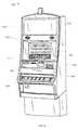
- FIG. 6is a perspective view of a wagering game machine, according to example embodiments of the invention.
- the description that followsincludes exemplary systems, methods, techniques, instruction sequences, and computer program products that embody techniques of the present inventive subject matter. However, it is understood that the described embodiments may be practiced without these specific details. For instance, although examples refer to accessing a structure to determine properties of light bars that constitute a light chain, in other embodiments, the light bars may be queried to determine the properties of the light bars. Also, although examples refer to chaining light bars comprising LEDs, in other embodiments, any suitable lighting devices may be chained together. In other instances, well-known instruction instances, protocols, structures, and techniques have not been shown in detail in order not to obfuscate the description.
- Light effect scriptsdictate how light effects should be displayed across multiple light bars on wagering game machines.
- Alight effect scriptindividually addresses and controls light effect(s) across each of the multiple light bars. For example, to generate a light effect of light appearing to move across multiple light bars, each light bar in the multiple light bars is individually addressed and controlled. Attributes and timing for each of the multiple light bars are coded, into the script, on a frame-by-frame basis because each of the light bars have a different behavior from one light frame (or one time instant) to the next.
- Individually programming each light bar to generate the light effectscan involve determining an exact timing (e.g., when the light source elements in the light bars turn ON/OFF) and attributes (e.g., intensity, color, etc.) or range of attributes for each of the light bars.
- timinge.g., when the light source elements in the light bars turn ON/OFF
- attributese.g., intensity, color, etc.
- the light effectis produced.
- each light barcan be a time-intensive and labor-intensive task.
- the amount of effort associated with individually programming attributes and timing of each light bar to generate the light effectsonly increases with the number of light bars involved in producing the light effects.
- a light effect script that individually addresses each light baris static and cannot handle variations in the light bars (e.g., number and type of light bars) and variations in configuration (e.g., a change in flow of light from one light bar to another). For example, if the number or configuration of light bars across which the light effects are to be produced is changed, the timing and attributes of the light bars may have to be recalculated and the light effect script may have to be reprogrammed to generate the light effects across the new light bars.
- Lighting devicese.g., light bars, light strips, light panels, etc.
- Chaining the lighting devices togetherrefers to grouping individual light devices into a logical group (hereinafter referred to as a “light chain”).
- the group of lighting devices that constitute the light chaincan be addressed and controlled as a single unit. Chaining the lighting devices facilitates configuration of a flow path that describes how light should flow through a light chain from one lighting device to a next lighting device.
- a system or light effect scriptcan use light chain commands to address and control the light chain as a single unit to switch ON/OFF the constituent lighting devices, display fade in/fade out effects across the constituent lighting devices, display moving light effects across the constituent lighting devices, display gradient effects across the constituent lighting devices, etc.
- a light chain commandcan control a mixture of different types of lighting devices as a single unit.
- a light chaincan be comprised of light bars, and an LED light strip.
- a light enginecan determine a number of lighting devices that constitute the light chain, and a chaining configuration (e.g., flow of light from one lighting device to another in the light chain, orientation of the lighting devices, order of the lighting devices, hierarchy of the lighting devices, etc.).
- the light enginecan determine attributes of the constituent lighting devices and compute timing to produce the light effect.
- the light enginegenerates output lighting device commands for controlling the lighting devices and/or light source elements of the constituent lighting devices.
- the light enginecan dynamically handle a variation in the number or chaining configuration of the lighting devices that constitute the light at runtime. Accordingly, the light engine can generate appropriate output lighting device commands to display the appropriate light effects.
- Chaining lighting devices in conjunction with a dynamic determination of lighting device attributes and timing valuesallows for a display of complex light effects with minimal user input, and allows for granularity independent rendering of light effects irrespective of the number or chaining configuration of the lighting devices across which the light effects are to be displayed.
- FIG. 1A and FIG. 1Bdepict conceptual diagrams of an example system that uses a light chain to produce light effects across a group of lighting devices.
- FIG. 1Aconceptually depicts operations of the server 104 and the light engine 112 to carry out light chain commands to produce light effects.
- FIG. 1Bcontinues from FIG. 1 and conceptually depicts operations of the light engine 112 , and the light control board 106 to carry out the light chain commands.
- the server 104may be a wagering game server that controls and presents wagering games on the wagering game machine 102 , a bonus game server that presents bonus games or rewards in response to game-based events, a dedicated lighting server, etc.
- the server 104is communicatively coupled to the light engine 112 , and the light engine 112 is coupled to the lighting control board 106 .
- the light engine 112has access to a lighting device chain structure 110 .
- the lighting control board 106controls lighting of light source elements on the wagering game machine 102 .
- Embodimentscan vary the architecture of the system.
- the server 104can host the light engine 112 and/or the lighting device chain structure 110 .
- the light engine 112can be implemented on a machine separate from the server, and the lighting device chain structure 110 can be implemented in a storage device separate from the server 104 and the light engine 112 .
- the lighting device chain structurecan be implemented as hardware (e.g., a hardware table) in the light engine 112 or the server 104 , as a structure(s) encoded in a network attached storage device, as a structure(s) encoded in a storage device local to the light engine 112 , etc.
- the server 104detects an event for which light effects should be produced at the wagering game machine 102 .
- the server 104can detect a multitude of various events and combinations of events and/or condition for a lighting effect(s). For example, the server 104 may detect or receive a notification of a game-based event and determine one or more lighting effects associated with the game-based event. As another example, the server 104 can detect fulfillment of a time based condition. The server 104 can determine that a light effect should be produced at the wagering game machine 102 when a specified time interval has elapsed, perhaps since a wagering game machine has been active.
- the server 104selects and transmits a light effects script 108 with light chain commands that include CHAIN_ROTATE_RT and CHAIN_FILL to the light engine 112 .
- the server 104can select a light script that maps directly to an event or that maps indirectly to an event.
- a light scriptcan map indirectly to an event through a light effect representation, for example.
- an eventcan map to a light effect category “Celebrate Bonus Win,” which is associated with a particular light script.
- a light chain commandaddresses a light chain and identifies light effects that should be generated across the light chain.
- the light chainis a logical grouping of lighting structures bars on the wagering game machine that allows the group of light bars that constitutes the light chain to be addressed as a single unit (e.g., using a single light chain command).
- a light chainmay comprise the light bar 120 and the light bar 126 .
- a single light chain commanddirecting that light in the light chain move to the right may be issued.
- the server 104selects the light effects script 108 .
- FIG. 1depicts the light effect script 108 as comprising two light chain commands—the CHAIN_FILL command and the CHAIN_ROTATE_RT command.
- the light effects script 108could comprise any suitable number of light chain commands.
- the light effect scripts 108may be part of another script that comprises mechanical commands, audio commands, other lighting commands, etc.
- the CHAIN_FILL and CHAIN_ROTATE_RT commandsmay be preceded by a PLAY_AUDIO command and may be followed by a STOP_AUDIO and MOVE_STRUCTURE command.
- the server 104then transmits the selected light effects script 108 to the light engine 112 .
- a script interpretermay identify the light chain command, and pass the light chain command along with parameters of the light chain command to the light engine 112 .
- the wagering game machine 102selects the light effects script 108 , and transmits the light effects script 108 to the light engine 112 .
- the server 104transmits the light effects script 108 to the wagering game machine 102 , where the wagering game machine 202 executes the light effect script 108 , identifies the light chain commands, and passes the light chain commands to the light engine 112 .
- the light engine 112parses the CHAIN_FILL and the CHAIN_ROTATE_RT commands and determines parameters of the light chain commands.
- the parameters of a light chain commandtypically comprise a light chain identifier, which is associated with an indication of the lighting devices that constitute the light chain.
- the light chain commandmay also indicate other parameters such as a light color, a light intensity, a time for which the light effect should be displayed, etc.
- the parameters of the light chain commandmay vary depending on the light effect to be displayed on the wagering game machine 202 .
- the light engine 112parses the CHAIN_FILL command for setting the color of light source elements in the light chain, and determines that the color of the light source elements in the light chain identified by “CHAIN — 1” should be set to blue. Also, the light engine 112 parses the CHAIN_ROTATE_RT command and determines that the light colors of the light source elements, in the light chain CHAIN — 1, should rotate to the right within a time interval of 5 seconds. To illustrate another example of a light chain command, the light engine 112 may analyze a “CHAIN_GRADIENT” command and determine a beginning light color and an ending light color. The CHAIN_GRADIENT command may also indicate a light intensity, a beginning light intensity, an ending light intensity, etc.
- the light engine 112determines lighting devices that constitute the light chain indicated by the light chain commands.
- the light engine 112accesses the lighting device chain structure 110 to determine the lighting devices that constitute the light chain represented by the light chain identifier.
- the lighting device chain structure 100represents an association or mapping between the lighting devices that constitute the light chain and the light chain identifier.
- the lighting device chain structure 110indicates the lighting devices that should be treated as a single unit when presenting light effects.
- the chain identifiercan be manually assigned or dynamically assigned to lighting devices. As an example of a dynamic assignment, the light engine (or another component, process, etc.) can detect or receive notification of coupling of a new lighting device to a lighting device already associated with a light chain.
- the light engine 112accesses the lighting device chain structure 110 and determines that the light chain represented by CHAIN — 1 comprises a light bar 120 and a light bar 122 .
- the lighting device chain structure 110can also indicate an order in which the light bars 120 and 122 are chained, so that the light engine 112 can determine a flow path for light effects across the light chain.
- the order in which the light bars are chaineddefines a flow of light in the light source elements from one light bar to another.
- the order of the lighting device in a light chaincan be indicated explicitly (e.g., order values) or implicitly (e.g., as they occur in a data structure).
- the light engine 112determines, based on information in the lighting device chain structure 110 , that the light bar 122 follows the light bar 120 for ordering. In other words, movement of light (in the light chain) starts at the light bar 120 and moves to the light bar 122 .
- the light engine 112can also determine other attributes of the light chain and/or the constituent lighting devices.
- the light engine 112determines attributes of the constituent lighting devices and determines timing to implement the chain commands.
- attributesinclude a position of and a number of light source elements in each of the lighting devices that constitute the light chain, a position of the light bars 120 and 122 , color, intensity, tilt, pan, etc. of the light source elements that constitute the light bars 120 and 122 .
- the timing of operations for the light barscan indicate a time instant at which the light source elements are switched ON/OFF, a time interval for which the light effects indicated by the light chain command should be displayed, etc.
- the light engine 112determines how to manipulate the lighting devices based on the parameters of the light chain command, attributes of the lighting devices, and timing to generate the light effects.
- the light engine 112may determine a total number of and identifiers of light bars across which the light effects should be produced. As mentioned above, the light engine can also determine and use attributes of the light chain. Examples of light chain attributes include configuration (e.g., circle, frame, etc.), resolution of the light chain based on the attributes and number of constituent lighting devices, capabilities of the light chain based on the aggregate capabilities of the constituent lighting devices. The attributes of the constituent lighting devices can be maintained in the lighting device chain structure, or in a separate structure. In other embodiments, the light engine 112 can access/query device drivers to determine attributes of the light bars 120 and 122 . The attributes that can be determined and techniques for determining the attributes can vary with each light chain.
- the light engine 112can determine operations to implement the chain commands. For example, for the CHAIN_FILL light chain command, the light engine 112 may determine that each of the light bars should display a blue color with a high intensity. For the CHAIN_ROTATE_RT command, the light engine 112 may determine that to rotate the light around two light bars in 5 seconds, light transitions (e.g., from one light bar to a next light bar) should take place every 2.5 seconds. Additionally, the light engine 112 may also determine a time instant at which each of the light bars should begin displaying the light transitions in order to generate the rotating light effects.
- the CHAIN_FILL light chain commandthe light engine 112 may determine that each of the light bars should display a blue color with a high intensity. For the CHAIN_ROTATE_RT command, the light engine 112 may determine that to rotate the light around two light bars in 5 seconds, light transitions (e.g., from one light bar to a next light bar) should take place every 2.5 seconds. Additionally, the light engine 112 may also
- the light engine 112may also determine position of structures that do not emit light.
- some or all of the light source elementsmay be housed in metal or plastic containers to focus a light beam in a particular direction.
- a light source elementmay be housed in an opaque container with a lens on the top that focuses light in the upwards direction.
- the light engine 112may determine an angle by which to rotate or a distance by which to move the containers to change the direction of the light beam. For example, in order to direct the light beam in the downwards direction, the light engine 112 may determine the container should be rotated by 180 degrees. As another example, light engine 112 may determine an angle by which a yoke should be rotated in order to change the direction of the light beam.
- the light engine 112may also determine how reflectors should be moved so that the light beams from the light source elements reflect off of the reflectors to produce the desired light effects.
- the reflectorsmay be moved around to help direct or guide the light beam in a particular direction.
- FIG. 2depicts the wagering game machine 102 with four light bars 120 , 122 , 124 , and 126 respectively affixed above a secondary display 128 , on a right side of the wagering game machine 102 , below a payout mechanism 130 , and on a left side of the wagering game machine 102 .
- the light barscomprise a set of light source elements. Examples of light source elements include light emitting diodes (LEDs), light bulbs, lamps, fluorescent lights, high intensity discharge lamps (HID lamps), and gas discharge lamps. In some implementations, the light bars comprise a set of LED light pixels.
- Each LED light pixelcan comprise any suitable number of red, green, and blue LEDs that can be used to display a desired color.
- the light barsmay comprise any suitable number of LED light pixels (e.g., 16 LED light pixels, 32 LED light pixels, etc.).
- the wagering game machine 102can comprise any suitable number of light bars.
- the wagering game machine 102can comprise eight light bars—two light bars affixed above the secondary display 128 , two light bars on the right side, two light bars on the left side, and two light bars on below the payout mechanism 130 of the wagering game machine 102 .
- the wagering game machine 102can comprise any suitable lighting structure that constitutes any suitable light source elements.
- the wagering gamemachine 102may comprise strip lights (instead of light bars) comprising multiple LEDs—each of which emit different colored light.
- the light barmay comprise lamps covered with colored glass lenses or gels so that the lamps project different colors of light.
- the light engine 112generates and transmits, to the lighting control board 106 , a set of output lighting device commands to implement the light chain commands.
- the light engine 112can generate output lighting device commands, in this case bar commands, in accordance with different techniques.
- the light engine 112maps or translates the light chain commands to lighting device commands.
- the light enginecan consult libraries of lighting device commands, and build output lighting device commands based on the targeted lighting device and attributes. The generation of lighting device commands for light chain commands will vary based on the attributes of the light chain, parameters of the light chain commands, attributes of the lighting devices, etc. In FIG.
- the light engine 112determines that the CHAIN_FILL command is implemented with a BAR_FILL command for each constituent light bar in FIG. 2 .
- the light engine 112In the output lighting device commands 114 , the light engine 112 generates lighting device commands BAR_FILL (BAR 120 , Blue) and BAR_FILL (BAR 122 , Blue) in response to the CHAIN_FILL command to indicate the light source elements in the light bars 120 and 122 should display a blue color.
- BAR_FILLBAR 120 , Blue
- BAR_FILLBAR 122 , Blue
- the light engine 112determines that the chain command can be implemented with BAR_SHIFTRT commands for each constituent light bar, as well as a DELAY command between the BAR_SHIFTRT commands. Instead of carry over the parameter value of 5 seconds from the light chain command, the light engine 112 determines that a timing parameter for the BARSHIFT_RT commands should be set to 2.5 seconds.
- the output lighting device command BAR_SHIFTRT(BAR 120 , 2.5 seconds) indicates that the light in the light source elements comprising the light bar 120 should be shifted to the right so that light shift effects are completed in 2.5 seconds (determined as the total amount of time the rotating light effect should be displayed (e.g., 5 seconds) divided by the number of light bars in the light chain (e.g., 2)).
- the DELAY commandcan indicate a time interval for which the lighting control board 106 should wait before initiating the BAR_SHIFTRT command for the light bar 122 .
- the lighting control board 106controls the light bars 120 and 122 that constitute the light chain in accordance with the output lighting device commands to produce the light effects. Based on the output lighting device commands 114 received from the light engine 112 , the lighting control board 106 can generate control commands to control lighting control structures and consequently the attributes of the light source elements in the light bar.
- the lighting control structurescan comprise dimmers and faders that control the intensity of the light emitted by light source elements.
- the lighting control structuresmay also comprise automated lighting controllers that control movement, orientation (e.g., pan and tilt), and color of lights.
- the light control boardmay comprise a DMX controller that receives the output lighting device commands, and generates and transmits DMX data to the lighting control elements. For example, in response to receiving the BAR_FILL commands, the lighting control board 106 may generate DMX data (or other digital data) that directs dimmers to vary intensity of light emitted by light source elements that constitute the light bar in order to display the blue color.
- any suitable number of lighting devicescan be chained together to form a light chain and that the lighting devices in the light chain can be chained together in any order.
- multiple light chainscan be implemented on a wagering game machine using the same lighting devices.
- the light bars 120 , 122 , 124 , and 126can be chained to form a first light chain, while the light bars 122 and 126 may be chained together to form a second light chain.
- different light chainsmay comprise the same light bar(s) chained together using different combinations.
- a first light chainmay comprise the light bars 120 , 122 , and 126 chained together so that light moves from the light bar 120 , to the light bar 122 , and finally to the light bar 126 .
- a second light chainmay comprise the same three light bars 120 , 122 , and 126 chained in a different order so that the lighting effects begin at the light bar 126 and move from the light bar 126 , to the light bar 120 , and finally to the light bar 122 .
- the number of light bars in the light chaincan be changed at any point in time without affecting the light chain commands in the light effect script 108 or affecting execution of the light effect script 108 .
- the light effect scriptis independent of the number of the light bars that constitute the light chain and the number of light source elements in each light bar.
- the light effect script 108is a generic script that addresses the light chain and that allows for dynamic querying of a current configuration of the light bars in order to create light effects. Because the light effect script 108 addresses the light chains instead of individual light bars, the light effect script 108 is adaptable to variations in hardware configurations.
- the lighting device chain structure 110may be updated to reflect changes made to the light bars that constitute the light chain.
- the lighting device chain structure 110may be updated to add the light bar 126 to the light chain identified by “CHAIN — 1”.
- CHAIN — 1When light commands that address CHAIN — 1 are received, the light bars 120 , 122 , and 124 are identified as the light bars that constitute CHAIN — 1 and light effects are displayed across the three light bars 120 , 122 , and 124 as described with reference to FIG. 1 .
- the light barsmay comprise variable-wavelength light source elements and the light engine 112 may determine wavelengths of light that the light source elements should emit in order to produce light with varying colors.
- parameters of the BAR_FILL command in the output lighting device commands 114may comprise the light bar identifier and a wavelength of the light color that should be emitted by the light source elements.
- BARFILLBAR 120 , 475 nm
- BARFILLmay indicate that the light source elements in the light bar 120 should emit color with a wavelength of 475 nm (i.e., a blue colored light).
- the operationscan be performed by logic not described in the block diagrams.
- the operationscan be performed by executing instructions residing on machine-readable media (e.g., software), while in other embodiments, the operations can be performed by hardware and/or other logic (e.g., firmware).
- the operationscan be performed in series, while in other embodiments, one or more of the operations can be performed in parallel.
- some embodimentscan perform less than all the operations shown in any flow diagram.
- FIG. 2is a flow diagram illustrating example operations for controlling light effects across a light chain.
- Flow 200begins at block 202 .
- a light chain commandthat indicates how lighting across a light chain should be varied is received.
- a light engine 112 of FIG. 1may receive the light chain command from a server.
- the servermay be a wagering gamemachine server that detects an event (e.g., a game based event, an elapsed time interval, etc.) and executes a light effect script based on the detecting the event. On encountering the light chain command in the light effect script, the server can pass the light chain command to the light engine.
- the light chain commandmay be received from the wagering game machine.
- a script interpreter running on the wagering game machinemay identify the light chain command and transmit the light chain command to the light engine 112 .
- the flowcontinues at block 204 .
- the light chain commandis parsed to determine parameters of the light chain command.
- At least one of the parameters of the light chain commandcan indicate a light chain identifier that represents lighting devices that constitute the light chain.
- the parameters of the light chain commandcan also indicate an intensity of light source elements that constitute the lighting devices, a time interval for which the light source elements should display a light effect, a starting and an ending light intensity (for light effects sselling a variation of light intensity), a starting and an ending color (for gradient light effects), etc.
- the flowcontinues at block 206 .
- the lighting devices that constitute the light chainare determined based on the light chain identifier indicated by the light chain command.
- the light chainis a logical grouping of multiple lighting devices. Once chained, the lighting devices that constitute the light chain may be addressed and controlled as a single unit.
- the light chain identifieridentifies the lighting devices that constitute the light chain and a configuration of the light lighting devices that constitute the light chain.
- the lighting devices that constitute the light chainmay be chained together in any order and the order of chaining indicates a flow path of light from one lighting device to a next lighting device. For example, it may be determined that a light bar on top of the wagering machine is chained to a light bar on the left of the wagering game machine.
- the two light barsare chained such that the light bar on the top is the first light bar while the light bar on the left is the second light bar in the light chain. Lighting effects, when initiated for the light chain will, therefore, start at the first light bar, move through the first light bar, spill into the second light bar, move through the second light bar, spill back into the first light bar (based on the light chain command), and so on. Different combinations of a same set of light bars may be assigned different light chain identifiers.
- the information about the light chaincan be stored in accordance with a variety of techniques (e.g., a light chain configuration file, a data structure indexed by the light chain identifier, a data structure identified by the chain identifier, etc.). The flow continues at block 208 .
- attributes of each lighting deviceare determined. Examples of attributes include intensity, color, number of nodes, type of lighting device, etc.
- Embodimentscan determine the lighting device attributes in accordance with different techniques.
- Embodimentscan indicate the attributes of each lighting device in the same data structure that indicates the light chain.
- Embodimentscan indicate the attributes in a separate structure referenced by or associated with the light chain data structure. For instance, a light engine can follow references in a light chain data structure to lighting device attribute data. In other embodiments, the light engine can query a store of attribute data or the lighting devices themselves to determine lighting device data.
- output lighting device commands to implement the light chain commandare determined. Parameter values for the commands are also determined. Determining the lighting device commands can involve multiple operations and/or multiple levels of analysis of the light chain command. In addition, the operations and/or level of analysis can vary based on the light chain command.
- associationscan be pre-defined between a light chain command and the one or more lighting device commands to implement the light chain command. There may be no parameter values, or the parameters values may translate directly from the light chain command to the implementing lighting device commands. For example, a color parameter value in a light chain command may carry over to the lighting device command(s). Although a single lighting device command may implement a light chain command, multiple instances of the lighting device command will implement the light chain command across the constituent lighting devices.
- a light chain commandcan cause a light chain to create a gradient effect.
- the light chain commandcan have parameters for a starting color and an ending color.
- An example light enginewill use the starting color for a lighting device command directed to a first constituent lighting device, and generate an ending color for the first constituent lighting device.
- the light enginewill determine a starting and ending color based on the configuration of the light chain.
- the light enginewill use the ending color from the light chain command, and generate a starting color.
- a light enginemay dynamically construct a sequence of implementing lighting device commands to implement a light chain command.
- a light chain commandcan be defined with tags and/or a description of the lighting effect to be created with the light chain command.
- the light enginecan analyze the tags and/or description and select lighting device commands based on evaluating names of lighting device commands against the tags and/or description.
- lighting device commandsmay be categorized.
- a light enginecan construct a sequence of lighting device commands based on analysis of the light chain command tags and/or description against categories of the lighting device commands. The light engine can further refine the selection of lighting device commands within categories based on analyzing tags of the lighting device commands.
- the lighting device commandsare not categorized, but have tags and/or descriptions.
- a light enginecan select lighting device commands based on the tags/descriptions, and heuristics or language analysis.
- timingit is determined if timing is a factor in the light chain command.
- a light enginecan determine that timing is a factor based on parameters of a light chain command.
- the light chain commandmay explicitly have a time parameter.
- timingcan be a factor because the light effect involves activity by the constituent lighting devices at different times (e.g., a light effect that moves across constituent lighting devices).
- the light enginecan determine that timing is a factor based on the light chain command (e.g., a light chain command to cause a moving light effect has a timing element), based on parameters of implementing lighting device commands (e.g., output lighting device commands have a timing parameter), etc.
- controlflows to block 214 .
- timingis not a factor then control flows to block 216 .
- timing values for output lighting device commandsare computed. It may also be determined delay should be utilized to implement the light chain command. Computing time values and/or determining utility of delay can range from less complex operations to more complex operations.
- a light enginecan divide the timing value of the light chain command by the number of constituent lighting devices. Similarly, the light engine can insert delay between output lighting device commands of different lighting devices. In other cases, the light engine may evaluate the lighting device attributes, characteristic of a lighting effect (e.g., perceived speed of a light effect across constituent lighting devices), current environment conditions (e.g., timing can vary or depend upon number of players or whether a bonus is occurring), etc.
- the light enginemay compute start time and end time parameters as well as duration.
- a command sequence to implement the light chain commandis constructed.
- the command sequenceis constructed with the lighting device commands and parameter values determined at block 210 .
- the command sequenceis also constructed based on the timing values and delay, if any, determined at block 214 .
- a light engineestablishes an order for the lighting device commands to occur.
- the light enginecan construct the command sequence in accordance with the order of the lighting devices (i.e., add lighting devices commands as it traverses the constituent lighting devices of the light chain).
- the light enginemay modify an initially constructed command sequence based on subsequent passes of the command sequence. For example, the light engine can evaluate the command sequence to determine whether later added lighting device commands affect predecessor lighting commands in the command sequence.
- the light enginecan construct a command sequence or modify a command sequence based on conditionals or rules defined for light chain commands, lighting device commands, lighting devices, user preference data, gaming establishment preference/configuration data, etc.
- the light enginecan communicate the command sequence in different forms and in accordance with various techniques.
- the light enginemay generate an executable/interpretable file (e.g., a script), and then transmit the file for execution by another device and/or process.
- the light enginemay communicate the sequence of commands to another device (e.g., lighting controller) by a variety of means (e.g., streaming the sequences, issuing each command, etc).
- the light enginecan implement delay with a DELAY command, or implement the delay by waiting to send a next command.
- Light chaining and dynamic controlling of multiple lighting devices that constitute a light chainimproves efficiency of producing light effects, including the gradient light effect.
- Manual programming of individual light bars to produce the gradient light effect across the multiple light barscan be very tedious. This is because displaying the gradient light effect requires knowledge of the number of light bars across which the gradient light effect is to be produced, and also involves calculating a gradient step based on the number of light bars involved and the desired variation of color. In other words, a step function at any particular light bar in the multiple light bars should be known and the each light bar should be independently programmed so that the light source elements in each of the multiple light bars, collectively, produce the gradient light effect.
- Chaining light bars together to operate as a single unitimproves efficiency and ease to dynamically generate the gradient effect without prior knowledge of the number of light bars or number of light source elements in each light bar as will be described with reference to FIG. 3 .
- FIG. 3is a flow diagram illustrating example operations for displaying a gradient light effect across a light chain.
- Flow 300begins at block 302 .
- a light chain command for generating a color gradient light effect across a light chain(“gradient light chain command”) is received.
- a server or the wagering gamemachinemay execute a light effect script in response to detecting an event and a script interpreter on the server/wagering game machine may identify the gradient light chain command and pass the gradient light chain command to a light engine.
- the flowcontinues at block 304 .
- the gradient light chain commandis parsed to determine parameters of the gradient light chain command.
- the gradient light chain commandcomprises a parameter values that at least indicate a light chain across which the gradient light effect should be displayed, a beginning color of the gradient, an ending color of the gradient, and a light intensity.
- a light chain identifiermay be determined from the parameters of the gradient light chain command.
- the light chain identifieridentifies lighting devices, on one or more wagering game machines, that are logically grouped together to form the light chain.
- the light chain identifiercan also be used to determine an order in which the light bars of the light chain are linked so as to define a flow of light from one lighting device to another lighting device within the light chain.
- the beginning and ending colors of the gradientmay be indicated, in the gradient light chain command, in terms of RGB values.
- CHAIN_GRADIENTCHAIN_GRADIENT (CHAIN — 1, 255,0,0, 0,0,255) may indicate that the gradient light effect should be displayed across CHAIN — 1 such that the beginning color of the gradient is red and the ending color of the gradient is blue.
- the beginning and the ending colors of the gradientmay be indicated using pre-defined words.
- the gradient light chain commandmay be received in the form CHAIN_GRADIENT (CHAIN — 1,RED,BLUE).
- color transitions in the light chainmay be indicated in terms of a percentage.
- the gradient light chain commandmay indicate that 80% of the light chain should display a hue of red and 20% of the light chain should display a hue of blue.
- the flowcontinues at block 306 .
- the light lighting devices that constitute the light chainare determined based on the light chain identifier. For example, a lighting device chain structure or a light chain configuration file can be accessed to determine lighting device identifiers of the lighting device that constitute the light chain. The lighting device identifiers may also be indicative of properties of the lighting device. The lighting device identifiers can be used to determine a position (orientation) of the lighting device on the wagering game machine(s). In some implementations, a number of light source elements in each of the lighting device, a relative position of each of the light source elements, light source element identification numbers, etc., may also be determined. The flow continues at block 308 .
- a gradient step by which attributes of the lighting device that constitute the light chain should be variedis calculated.
- the gradient stepmay be used to determine a color gradient for the lighting device within the light chain.
- the gradient stepmay also be used to calculate a timing by which gradient effects should be displayed on the lighting device.
- the gradient step, by which attributes and timing of lighting device in the light chain should be varied,may be determined based on a total number of lighting device that constitute the light chain.
- the gradient stepmay also be determined based on the beginning color of the gradient, the ending color of the gradient, and a percentage (if specified) of the light chain that should comprise a certain hue of color.
- the gradient stepis determined as an inverse of the total number of lighting devices in the light chain. For example, if there are 4 light bars in the light chain, the gradient step may be determined to be 1 ⁇ 4. The flow continues at block 310 .
- the attributes and timing of the lighting devices that constitute the light chainare determined in order to generate the gradient light effect across the light chain. Based on knowledge of the beginning color, the ending color, and the gradient step, a proper transition from one color to another color across the light chain can be calculated by dividing the color transition by the total number of lighting devices in the light chain. Based on knowledge of the beginning color, the ending color and the gradient step, a percentage of color variation across the lighting devices that constitute the light chain can also be determined. Accordingly, the light intensity/light color of LED light pixels, for instance, in each of the lighting devices in the light chain can be scaled/varied by the determined percentage.
- the first light barshould display the range of colors that start with a color of 100% red and 0% blue and end with a color of 50% red and 50% blue. Additionally, it may be determined that the second light bar should display the range of colors that start with a color of 50% red and 50% blue and end with color of 0% red and 100% blue.
- a sequence of output lighting device commands to display the gradient light effectare transmitted and generated to a lighting control board.
- Each of the output lighting device commandscan indicate the parameter values and timing of light source elements that constitute a lighting device.
- BAR_GRADIENTBAR — 1, 255, 0, 0, 127, 0, 128) may indicate that the gradient light effect across the light bar BAR — 1 should range from 100% red to 50% red and 50% blue.
- BAR_GRADIENT(BAR — 2, 127, 0, 128, 0, 0, 255) may indicate that the gradient light effect across the light bar BAR — 2 should range from 50% red and 50% blue to 100% blue.
- the lighting control boardin turn, can receive the output lighting device commands and analyze the output lighting device commands.
- the lighting control boardcan translate the output lighting device commands into control data (e.g., DMX data) that indicates how lighting control structures (e.g., dimmers) should vary the attributes of light source elements that constitute lighting devices.
- each lighting device in the light chainmay be stored in specified memory locations.
- each light barmay be associated with a data structure that holds indications of light hue, light intensity, etc.
- light bar identifiers and corresponding memory addressesfrom where the attributes of the lighting devices can be retrieved may be transmitted.
- the lighting control unitcan, in turn, retrieve the set of output lighting device commands from memory and generate control data to vary attributes of the light source elements to produce the desired gradient light effect. From block 312 , the flow ends.
- the gradient stepcan be dynamically calculated based on determining, at runtime, the total number of lighting devices that constitute the light chain. This precludes the need for individually programming each lighting device in a set of multiple lighting devices to generate the gradient light effect.
- a light enginee.g., the light engine 112 of FIG. 1
- the number of lighting devices in the light chainmay change, e.g., from four light bars to six light bars.
- light engine 112can determine a new number of lighting devices that constitute the light chain, identify the lighting devices that constitute the light chain, accordingly calculate a new gradient step, and issue output lighting device commands for producing the gradient light effect.
- FIGS. 1-3describe light chains as constituting lighting devices on a single wagering game machine
- the light chaincan constitute lighting devices across any suitable number of wagering game machines and associate non-wagering game machines (e.g., overhead lighting devices associated with a bank of wagering game machines).
- Light chain commandsmay be executed (as described with reference to FIGS. 1-3 ) to produce light effects across multiple wagering game machines.
- a light chaincan constitute two light bars where a first light bar is located on a first wagering gamemachine and a second light bar is located on a second wagering gamemachine.
- the light engine 112can perform operations to display a gradient light effect across the two wagering game machines.
- the light engine 112could identify output lighting device commands associated with each of the two wagering game machines and accordingly transmit the appropriate output lighting device commands to the wagering game machines.
- the light enginemay determine a first set of output lighting device commands for the first light bar on the first wagering game machine and a second set of output lighting device commands for the second light bar on the second wagering game machine.
- the light enginecan transmit the first set of output lighting device commands to a lighting control board associated with the first wagering game machine and can transmit the second set of output lighting device commands to a lighting control board associated with the second wagering gamemachine, so as to generate the light effect indicated by the light chain command.
- a common lighting control unitmay control the light bars of multiple wagering game machines in a casino.
- the light enginemay, therefore, transmit the output lighting device commands to the common lighting control unit and direct the lighting control unit to vary lighting of the light bars in accordance with the output lighting device commands so as to generate the light effects.
- the light engine 112may also control light source elements that provide lighting on a casino floor.
- the light engine 112may control a color, intensity, and position of striplights.
- the striplightsmay comprise light bulbs covered with colored glass or gels.
- the light enginemay control an intensity of light emitted by various light bulbs that constitute the striplight to produce light effects across the casino.
- the striplightcan even comprise LEDs.
- the light engine 112may control timing and attributes (e.g., intensity, color, direction of light) of spotlights to produce light shows across the casino.
- This sectiondescribes an example operating environment and presents structural aspects of some embodiments. This section includes discussion about wagering game networks and wagering game machine architectures.
- FIG. 4is a block diagram illustrating a wagering game network 400 , according to example embodiments of the invention.
- the wagering game network 400includes a plurality of casinos 412 , 420 , and 422 connected to a communications network 414 .
- the plurality of casinos 412 , 420 , and 422is also connected to a light engine 431 and a lighting device chain structure 418 via the communications network 414 .
- Each casino 412includes a local area network 416 , which includes an access point 404 , a wagering game server 406 , and wagering game machines 402 .
- the access point 404provides wireless communication links 410 and wired communication links 408 .
- the wired and wireless communication linkscan employ any suitable connection technology, such as Bluetooth, 802.11, Ethernet, public switched telephone networks, SONET, etc.
- the wagering game server 406can serve wagering games and distribute content to devices located in other casinos 412 or at other locations on the communications network 414 .
- the light engine 431implements functionality for dynamically determining a set of lighting device commands to implement a light chain command across multiple lighting devices that constitute a light chain.
- the wagering game server 406detects a game based event, executes a light effect script in response to detecting the game-based event, identifies a light chain command, and transmits the light chain command to the light engine 431 .
- the wagering game machine 402 or any suitable server in the network 400may identify and transmit the light chain command to the light engine 412 .
- the light engine 431selects a light chain command responsive to the wagering game server 406 detecting a trigger for a light effect.
- the light chain commandreferences a light chain, which represents a combination of one or more light bars across which light effects should be displayed.
- the light engine 412queries, using the light chain identifier, the lighting device chain structure 418 and determines the light bars that constitute the light chain.
- the light engine 431also determines attributes of the light bars based on knowledge of the light bars that constitute the light chain, so as to generate light effects in accordance with the light chain command.
- the light engine 431generates a set of output lighting device commands and transmits the set of output lighting device commands to a lighting control board.
- the lighting control boardcan, based on the output lighting device commands, generate control commands to vary the attributes and timing of each light source element that constitutes the light bars.
- the wagering game machines 402 described hereincan take any suitable form, such as floor standing models, bartop models, workstation-type console models, etc., which can be associated with lighting devices. Further, the wagering game machines 402 can be primarily dedicated for use in conducting wagering games, or can include non-dedicated devices, such as mobile phones, personal digital assistants, personal computers, etc. In one embodiment, the wagering game network 400 can include other network devices, such as accounting servers, wide area progressive servers, player tracking servers, and/or other devices suitable for use in connection with embodiments of the invention.
- wagering game machines 402 and wagering game servers 406work together such that a wagering game machine 402 can be operated as a thin, thick, or intermediate client.
- a wagering game machine 402can be operated as a thin, thick, or intermediate client.
- one or more elements of game playmay be controlled by the wagering game machine 402 (client) or the wagering game server 406 (server).
- Game play elementscan include executable game code, lookup tables, configuration files, game outcome, audio or visual representations of the game, game assets or the like.
- the wagering game server 406can perform functions such as determining game outcome or managing assets, while the wagering game machine 402 can present a graphical representation of such outcome or asset modification to the user (e.g., player).
- the wagering game machines 402can determine game outcomes and communicate the outcomes to the wagering game server 406 for recording or managing a player's account.
- either the wagering game machines 402 (client) or the wagering game server 406can provide functionality that is not directly related to game play.
- account transactions and account rulesmay be managed centrally (e.g., by the wagering game server 406 ) or locally (e.g., by the wagering gamemachine 402 ).
- Other functionality not directly related to game playmay include power management, presentation of advertising, software or firmware updates, system quality or security checks, etc.
- wagering game network componentse.g., the wagering game machines 402
- the wagering game machines 402can include hardware and machine-readable media including instructions for performing the operations described herein.
- the following sectiondescribes architecture of the wagering game machine.
- FIG. 5is a block diagram illustrating wagering game machine architecture, according to example embodiments of the invention.
- the wagering game machine architecture 500includes a wagering game machine 506 , which includes a central processing unit (CPU) 526 connected to main memory 528 .
- the CPU 526can include any suitable processor, such as an Intel® Pentium processor, Intel® Core 2 Duo processor, AMD OpteronTM processor, or UltraSPARC processor.
- the main memory 528comprises a wagering game unit 532 .
- the wagering game unit 532can present wagering games, such as video poker, video blackjack, video slots, video lottery, etc., in whole or part.
- the wagering game machine 506also comprises a lighting controller 536 .
- the lighting controller 536can be an application specific integrated circuit, a lighting control board, field programmable gate array, co-processor, etc.
- the lighting controller 536implements functionality to control lighting on the wagering gamemachine 502 in accordance with instructions from a light engine (e.g., as described with reference to FIGS. 1-4 ).
- the lighting controller 536receives output lighting device commands from a light engine, and generates and transmits digital or analog control data to a set of lighting control structures (e.g., dimmers, faders, rotary encoders, etc.).
- the control datacan indicate a current (or voltage) that should be applied to, an intensity of, and an angle of rotation of structures that house the light source elements of each lighting device that constitutes a light chain.
- the lighting controller 536may transmit DMX data to the lighting control structures and the lighting control structures can, in turn, control the light source elements.
- the lighting controller 536can vary the inputs to light source element LEDs, for example, in each of the lighting devices so as to generate light effects in accordance with the light chain commands.
- a light enginecan be embodied on a server as described with reference to FIG. 4 , which communicates with the lighting controller 536 . But in some embodiments, functionality of a light engine can be implemented at both a server and a wagering game machine, or in the wagering game machine alone.
- the memory unit 528can comprise a light engine (not shown) that performs the functionality for receiving light chain commands, determining lighting devices that constitute the light chain, and determining output lighting device commands with any determined parameter values and/or timing values.
- embodimentscan implement an architecture that allows for a wagering gamemachine to control light chains on other wagering game machines, or even a light chain that spans multiple wagering game machines and non-wagering game machines.
- a light enginecan be installed on a wagering game machine that issues lighting device commands to machines associated with light chains.
- multiple wagering game machinescan comprise light engines.
- One of the wagering game machinescan be designated as a currently active light engine, while the other light engines operate as failover light engines.
- the CPU 526is also connected to an input/output (I/O) bus 522 , which can include any suitable bus technologies, such as an AGTL+ frontside bus and a PCI backside bus.
- the I/O bus 522is connected to the lighting controller 536 , a payout mechanism 508 , primary display 510 , secondary display 512 , value input device 514 , player input device 516 , information reader 518 , and storage unit 530 .
- the player input device 516can include the value input device 514 to the extent the player input device 516 is used to place wagers.
- the I/O bus 522is also connected to an external system interface 524 , which is connected to external systems 504 (e.g., wagering game networks).
- the wagering game machine 506can include additional peripheral devices and/or more than one of each component shown in FIG. 5 .
- the wagering game machine 506can include multiple external system interfaces 524 and/or multiple CPUs 526 .
- any of the componentscan be integrated or subdivided.
- Machine-readable mediaincludes any mechanism that provides (i.e., stores and/or transmits) information in a form readable by a machine (e.g., a wagering game machine, computer, etc.).
- a machine-readable storage mediuminclude read only memory (ROM), random access memory (RAM), magnetic disk storage media, optical storage media, flash memory machines, etc.
- a machine-readable signal transmission mediuminclude copper wires, fiber optics, wireless transmission media, etc.
- FIG. 6is a perspective view of a wagering game machine, according to example embodiments of the invention.
- a wagering game machine 600is used in gaming establishments, such as casinos.
- the wagering game machine 600can be any type of wagering game machine and can have varying structures and methods of operation.
- the wagering gamemachine 600can be an electromechanical wagering game machine configured to play mechanical slots, or it can be an electronic wagering gamemachine configured to play video casino games, such as blackjack, slots, keno, poker, blackjack, roulette, etc.
- the wagering game machine 600comprises a housing 612 and includes input devices, including value input devices 618 and a player input device 624 .
- the wagering game machine 600includes a primary display 614 for displaying information about a basic wagering game.
- the primary display 614can also display information about a bonus wagering game and a progressive wagering game.
- the wagering game machine 600also includes a secondary display 616 for displaying wagering game events, wagering game outcomes, and/or signage information. While some components of the wagering game machine 600 are described herein, numerous other elements can exist and can be used in any number or combination to create varying forms of the wagering game machine 600 .
- the value input devices 618can take any suitable form and can be located on the front of the housing 612 .
- the value input devices 618can receive currency and/or credits inserted by a player.
- the value input devices 618can include coin acceptors for receiving coin currency and bill acceptors for receiving paper currency.
- the value input devices 618can include ticket readers or barcode scanners for reading information stored on vouchers, cards, or other tangible portable storage devices.
- the vouchers or cardscan authorize access to central accounts, which can transfer money to the wagering gamemachine 600 .
- the player input device 624comprises a plurality of push buttons on a button panel 626 for operating the wagering game machine 600 .
- the player input device 624can comprise a touch screen 628 mounted over the primary display 614 and/or secondary display 616 .
- the various components of the wagering gamemachine 600can be connected directly to, or contained within, the housing 612 .
- some of the wagering gamemachine's componentscan be located outside of the housing 612 , while being communicatively coupled with the wagering game machine 600 using any suitable wired or wireless communication technology.
- the operation of the basic wagering gamecan be displayed to the player on the primary display 614 .
- the primary display 614can also display a bonus game associated with the basic wagering game.
- the primary display 614can include a cathode ray tube (CRT), a high resolution liquid crystal display (LCD), a plasma display, light emitting diodes (LEDs), or any other type of display suitable for use in the wagering gamemachine 600 .
- the primary display 614can include a number of mechanical reels to display the outcome.
- the wagering gamemachine 600is an “upright” version in which the primary display 614 is oriented vertically relative to the player.
- the wagering game machinecan be a “slant-top” version in which the primary display 614 is slanted at about a thirty-degree angle toward the player of the wagering game machine 600 .
- the wagering game machine 60000can exhibit any suitable form factor, such as a free standing model, bartop model, mobile handheld model, or workstation console model.
- a playerbegins playing a basic wagering game by making a wager via the value input device 618 .
- the playercan initiate play by using the player input device's buttons or touch screen 628 .
- the basic gamecan include arranging a plurality of symbols along a payline 632 , which indicates one or more outcomes of the basic game. Such outcomes can be randomly selected in response to player input. At least one of the outcomes, which can include any variation or combination of symbols, can trigger a bonus game.
- the wagering game machine 600can also include an information reader 652 , which can include a card reader, ticket reader, bar code scanner, RFID transceiver, or computer readable storage medium interface.
- the information reader 652can be used to award complimentary services, restore game assets, track player habits, etc.
Landscapes
- Circuit Arrangement For Electric Light Sources In General (AREA)
Abstract
Description
Claims (25)
Priority Applications (1)
| Application Number | Priority Date | Filing Date | Title |
|---|---|---|---|
| US13/109,427US8912727B1 (en) | 2010-05-17 | 2011-05-17 | Wagering game lighting device chains |
Applications Claiming Priority (2)
| Application Number | Priority Date | Filing Date | Title |
|---|---|---|---|
| US34530810P | 2010-05-17 | 2010-05-17 | |
| US13/109,427US8912727B1 (en) | 2010-05-17 | 2011-05-17 | Wagering game lighting device chains |
Publications (1)
| Publication Number | Publication Date |
|---|---|
| US8912727B1true US8912727B1 (en) | 2014-12-16 |
Family
ID=52015248
Family Applications (1)
| Application Number | Title | Priority Date | Filing Date |
|---|---|---|---|
| US13/109,427Active2033-10-16US8912727B1 (en) | 2010-05-17 | 2011-05-17 | Wagering game lighting device chains |
Country Status (1)
| Country | Link |
|---|---|
| US (1) | US8912727B1 (en) |
Cited By (9)
| Publication number | Priority date | Publication date | Assignee | Title |
|---|---|---|---|---|
| US20140206432A1 (en)* | 2013-01-22 | 2014-07-24 | Wms Gaming, Inc. | Configuring wagering game machines for gaming effects |
| US20140335956A1 (en)* | 2010-04-26 | 2014-11-13 | Wms Gaming, Inc. | Presenting lighting content in wagering game systems |
| US9728041B2 (en) | 2009-11-04 | 2017-08-08 | Bally Gaming, Inc. | Wagering game machine layout mapping |
| WO2017213821A1 (en)* | 2016-06-09 | 2017-12-14 | Konami Gaming, Inc. | Gaming machine, system, and method for an associated stage effect |
| US10032332B2 (en) | 2009-06-15 | 2018-07-24 | Bally Gaming, Inc. | Controlling wagering game system audio |
| US10269207B2 (en) | 2009-07-31 | 2019-04-23 | Bally Gaming, Inc. | Controlling casino lighting content and audio content |
| WO2020078793A1 (en)* | 2018-10-18 | 2020-04-23 | Signify Holding B.V. | Determining a light effect impact based on a determined input pattern |
| US10728989B2 (en) | 2017-03-02 | 2020-07-28 | Signify Holding B.V. | Lighting script control |
| US11386661B2 (en)* | 2017-09-18 | 2022-07-12 | Signify Holding B.V. | Method and system for creating a light script for a video |
Citations (134)
| Publication number | Priority date | Publication date | Assignee | Title |
|---|---|---|---|---|
| US5259613A (en) | 1992-04-08 | 1993-11-09 | Rio Hotel Casino, Inc. | Casino entertainment system |
| US5483631A (en) | 1990-05-01 | 1996-01-09 | Hitachi, Ltd. | Communication network management system for displaying operation states of network elements on a remote display unit |
| US5633933A (en) | 1994-06-10 | 1997-05-27 | Sun Microsystems, Inc. | Method and apparatus for a key-management scheme for internet protocols |
| US6040831A (en) | 1995-07-13 | 2000-03-21 | Fourie Inc. | Apparatus for spacially changing sound with display location and window size |
| US6081266A (en) | 1997-04-21 | 2000-06-27 | Sony Corporation | Interactive control of audio outputs on a display screen |
| US6146273A (en) | 1997-10-24 | 2000-11-14 | Mikohn Gaming Corporation | Progressive jackpot gaming system with secret bonus pool |
| US6217448B1 (en) | 1998-09-18 | 2001-04-17 | Mikohn Gaming Corporation | Controller-based linked gaming machine bonus system |
| US20010021666A1 (en) | 1999-12-22 | 2001-09-13 | Hiroshi Yoshida | Gaming machine |
| US20020010018A1 (en) | 1999-09-13 | 2002-01-24 | Lemay Steven C. | Bonusing apparatus and method for gaming system providing flexibility and interest |
| US20020055978A1 (en) | 2000-07-25 | 2002-05-09 | Samsung Electronics Co., Ltd. | Method for managing network when master disappears |
| US20020160826A1 (en) | 2001-04-27 | 2002-10-31 | Gomez Benjamin T. | Linked gaming machines |
| US20030002246A1 (en) | 2001-06-15 | 2003-01-02 | Apple Computers, Inc. | Active enclousure for computing device |
| US20030007648A1 (en) | 2001-04-27 | 2003-01-09 | Christopher Currell | Virtual audio system and techniques |
| US20030017865A1 (en) | 2001-07-19 | 2003-01-23 | Nicole Beaulieu | Gaming method and gaming apparatus with in-game player stimulation |
| US20030130033A1 (en) | 2002-01-09 | 2003-07-10 | Loose Timothy C. | Synchronization of display indicia on standalone gaming machines |
| US20030132722A1 (en) | 1993-11-12 | 2003-07-17 | Chansky Leonard M. | Theatrical lighting control network |
| US6647119B1 (en) | 1998-06-29 | 2003-11-11 | Microsoft Corporation | Spacialization of audio with visual cues |
| US20040072610A1 (en) | 2002-10-11 | 2004-04-15 | Rick White | Gaming machine and method having symbols capable of displaying movement |
| EP1439507A2 (en) | 2003-01-16 | 2004-07-21 | WMS Gaming Inc | Selectable audio preferences for a gaming machine |
| US20040160199A1 (en) | 2001-05-30 | 2004-08-19 | Color Kinetics, Inc. | Controlled lighting methods and apparatus |
| WO2004075129A1 (en) | 2003-02-20 | 2004-09-02 | Igt | Usb light controller for controlling a display on a light device in a gaming unit |
| WO2004075128A1 (en) | 2003-02-20 | 2004-09-02 | Igt | Gaming apparatus with controllable light device |
| US20040178750A1 (en)* | 2003-03-10 | 2004-09-16 | Belliveau Richard S. | Image projection lighting device displays and interactive images |
| WO2004086320A1 (en) | 2003-03-28 | 2004-10-07 | Igt | Gaming units with an enhanced group bonus round |
| US20040209692A1 (en) | 2003-04-17 | 2004-10-21 | Grips Elektronik G.M.B.H. | Player insert for a gaming machine, a gaming system and a method of operating a gaming system |
| WO2004014501A3 (en) | 2002-08-07 | 2005-01-13 | Bally Gaming Inc | Gaming machine with automatic sound level adjustment and method therefor |
| US6843723B2 (en) | 2000-10-04 | 2005-01-18 | Wms Gaming Inc. | Gaming machine with visual and audio indicia changed over time |
| US20050044500A1 (en) | 2003-07-18 | 2005-02-24 | Katsunori Orimoto | Agent display device and agent display method |
| US20050043090A1 (en) | 2000-10-04 | 2005-02-24 | Pryzby Eric M. | Audio network for gaming machines |
| US20050054440A1 (en) | 2003-09-10 | 2005-03-10 | Wms Gaming Inc. | Gaming machine with audio synchronization feature |
| US20050077843A1 (en) | 2003-10-11 | 2005-04-14 | Ronnie Benditt | Method and apparatus for controlling a performing arts show by an onstage performer |
| US20050116667A1 (en) | 2001-09-17 | 2005-06-02 | Color Kinetics, Incorporated | Tile lighting methods and systems |
| US20050128751A1 (en) | 2003-05-05 | 2005-06-16 | Color Kinetics, Incorporated | Lighting methods and systems |
| US20050153780A1 (en)* | 2004-01-12 | 2005-07-14 | Atronic International Gmbh | Multicolor top light for gaming machines |
| US20050164786A1 (en) | 2004-01-26 | 2005-07-28 | Wms Gaming Inc. | Gaming device having continuous rhythm reel sound |
| US20050164787A1 (en) | 2004-01-26 | 2005-07-28 | Wms Gaming Inc. | Gaming device with directional audio cues |
| US20050164788A1 (en) | 2004-01-26 | 2005-07-28 | Wms Gaming Inc. | Gaming device audio status indicator |
| US20050164785A1 (en) | 2004-01-26 | 2005-07-28 | Wms Gaming Inc. | Gaming device having independently selected concurrent audio |
| US20050174473A1 (en) | 1999-11-18 | 2005-08-11 | Color Kinetics, Inc. | Photography methods and systems |
| US20050200318A1 (en)* | 1992-09-25 | 2005-09-15 | Production Resource Group L.L.C. | Stage lighting lamp unit and stage lighting system including such unit |
| US20050239545A1 (en) | 2003-07-14 | 2005-10-27 | Bruce Rowe | Programmatic control of gaming devices |
| US6960136B2 (en) | 2000-10-04 | 2005-11-01 | Wms Gaming Inc. | Gaming machine with visual and audio indicia changed over time |
| US20050248299A1 (en) | 2003-11-20 | 2005-11-10 | Color Kinetics Incorporated | Light system manager |
| WO2005114599A1 (en) | 2004-05-13 | 2005-12-01 | Wms Gaming Inc. | Midi in a wagering game machine |
| WO2005113089A1 (en) | 2004-05-13 | 2005-12-01 | Wms Gaming, Inc. | Wagering game machine audio module interface |
| WO2005114598A1 (en) | 2004-05-13 | 2005-12-01 | Wms Gaming Inc. | Ambient audio environment in a wagering game |
| US6972528B2 (en) | 2003-11-21 | 2005-12-06 | Chiliang Shao | Structure for LED lighting chain |
| US6974385B2 (en) | 2000-10-04 | 2005-12-13 | Wms Gaming Inc. | Gaming machine with visual and audio indicia changed over time |
| US20050275626A1 (en) | 2000-06-21 | 2005-12-15 | Color Kinetics Incorporated | Entertainment lighting system |
| WO2005117647A1 (en) | 2004-05-28 | 2005-12-15 | Wms Gaming Inc. | Gaming device with attached audio-capable chair |
| US20050282631A1 (en) | 2003-01-16 | 2005-12-22 | Wms Gaming Inc. | Gaming machine with surround sound features |
| US20060009285A1 (en) | 2003-01-16 | 2006-01-12 | Wms Gaming Inc. | Gaming machine environment having controlled audio and visual media presentation |
| US20060025211A1 (en) | 2004-07-30 | 2006-02-02 | Wilday Peter B | Gaming system constructions and methods |
| US20060022214A1 (en) | 2004-07-08 | 2006-02-02 | Color Kinetics, Incorporated | LED package methods and systems |
| US6997803B2 (en) | 2002-03-12 | 2006-02-14 | Igt | Virtual gaming peripherals for a gaming machine |
| US20060046829A1 (en) | 2004-08-30 | 2006-03-02 | Wms Gaming Inc. | Gaming machine having a game outcome determined in response to an audio cue |
| WO2006033941A1 (en) | 2004-09-20 | 2006-03-30 | Wms Gaming Inc. | Virtual radio in a wagering game machine |
| WO2006017444A3 (en) | 2004-08-02 | 2006-03-30 | Wms Gaming Inc | Gaming machine with environment aware audio configuration |
| US20060076908A1 (en) | 2004-09-10 | 2006-04-13 | Color Kinetics Incorporated | Lighting zone control methods and apparatus |
| WO2006039323A1 (en) | 2004-09-30 | 2006-04-13 | Wms Gaming Inc. | Audio object location in a computerized wagering game |
| US7082572B2 (en) | 2002-12-30 | 2006-07-25 | The Board Of Trustees Of The Leland Stanford Junior University | Methods and apparatus for interactive map-based analysis of digital video content |
| WO2006017445A3 (en) | 2004-08-02 | 2006-08-24 | Wms Gaming Inc | Gaming machine with self-changing audio configuration |
| US7112139B2 (en) | 2001-12-19 | 2006-09-26 | Wms Gaming Inc. | Gaming machine with ambient noise attenuation |
| US20060244622A1 (en) | 2005-04-12 | 2006-11-02 | J & J Electronics, Inc. (A Corporation Of California) | Networkable controllers for LED lighting |
| US20070004510A1 (en) | 2004-01-12 | 2007-01-04 | Igt | Casino display methods and devices |
| US20070008711A1 (en) | 2005-07-11 | 2007-01-11 | Mox Tronix Co., Ltd. | Multifunction lighting and audio system |
| US20070032288A1 (en) | 2000-10-19 | 2007-02-08 | Igt | Remote configuration of gaming terminals |
| US20070036368A1 (en) | 2003-03-11 | 2007-02-15 | Igt | Differentiated audio |
| US7181370B2 (en) | 2003-08-26 | 2007-02-20 | Siemens Energy & Automation, Inc. | System and method for remotely obtaining and managing machine data |
| US20070086754A1 (en) | 1999-07-14 | 2007-04-19 | Color Kinetics Incorporated | Systems and methods for authoring lighting sequences |
| WO2006039284A3 (en) | 2004-10-01 | 2007-04-19 | Wms Gaming Inc | Audio markers in a computerized wagering game |
| US20070111776A1 (en) | 2005-11-17 | 2007-05-17 | Igt | Gaming machine with movable display |
| WO2007022343A3 (en) | 2005-08-17 | 2007-05-18 | Wms Gaming Inc | Wagering game system with independent volume control |
| US7228190B2 (en) | 2000-06-21 | 2007-06-05 | Color Kinetics Incorporated | Method and apparatus for controlling a lighting system in response to an audio input |
| WO2007022294A3 (en) | 2005-08-16 | 2007-06-07 | Wms Gaming Inc | Presenting streaming video content in a gaming machine |
| US20070218970A1 (en) | 2005-07-06 | 2007-09-20 | Bally Gaming, Inc. | Configurable celebration system |
| US20070218974A1 (en) | 2005-07-06 | 2007-09-20 | Bally Gaming, Inc. | Method for configuring celebration activity |
| US20070219000A1 (en) | 2006-03-16 | 2007-09-20 | Konami Gaming Incorporated | Gaming system recommending specific games |
| WO2007061904B1 (en) | 2005-11-17 | 2007-10-25 | Konami Gaming Inc | System and method for controlling volume associated with gaming system |
| WO2006125013A3 (en) | 2005-05-17 | 2007-11-01 | Wms Gaming Inc | Wagering game adaptive on-screen user volume control |
| WO2007133566A2 (en) | 2006-05-11 | 2007-11-22 | Wms Gaming Inc. | Audio management in a wireless wagering game |
| US20080039213A1 (en) | 2006-08-03 | 2008-02-14 | Wms Gaming Inc. | Gaming machine having auxiliary lighting feature |
| US20080094005A1 (en) | 2006-10-19 | 2008-04-24 | Philips Solid-State Lighting Solutions | Networkable led-based lighting fixtures and methods for powering and controlling same |
| US7364508B2 (en) | 2003-01-16 | 2008-04-29 | Wms Gaming, Inc. | Gaming machine environment having controlled audio and visual media presentation |
| US20080113715A1 (en) | 2006-11-09 | 2008-05-15 | Igt | Controllable array of networked gaming machine displays |
| WO2008057538A2 (en) | 2006-11-06 | 2008-05-15 | Wms Gaming Inc. | Wagering game machine with remote audio configuration |
| US20080113821A1 (en) | 2006-11-09 | 2008-05-15 | Igt | Gaming machine with vertical door-mounted display |
| US20080113796A1 (en) | 2006-11-09 | 2008-05-15 | Igt | Speaker arrangement and control on a gaming machine |
| US20080143267A1 (en)* | 2006-11-20 | 2008-06-19 | Neuman Robert C | Variable effect light string |
| US20080161108A1 (en) | 2004-05-13 | 2008-07-03 | Wms Gaming Inc. | Wagering Game Machine Digital Audio Amplifier |
| WO2008063391A3 (en) | 2006-11-10 | 2008-07-10 | Wms Gaming Inc | Wagering games using multi-level gaming structure |
| US20080176647A1 (en) | 2006-01-13 | 2008-07-24 | Acres-Fiore, Inc. | Method and apparatus for selectively indicating win proximity |
| US20080231203A1 (en) | 2005-07-27 | 2008-09-25 | Koninklijke Philips Electronics, N.V. | Lighting System and Method for Controlling a Plurality of Light Sources |
| US20080274793A1 (en) | 2007-05-04 | 2008-11-06 | Atlantic City Coin & Slot Service Company, Inc. | Lighting system for gaming devices and method of use |
| US7449839B1 (en) | 2007-01-10 | 2008-11-11 | Ching-Chao Chen | Structure of LED lighting chain |
| US20080278946A1 (en) | 2007-05-08 | 2008-11-13 | The Coleman Company, Inc. | Led spotlight |
| WO2008137130A1 (en) | 2007-05-07 | 2008-11-13 | Wms Gaming Inc. | Wagering game machine with scalable fidelity audio |
| US20080288607A1 (en) | 2002-03-07 | 2008-11-20 | Cisco Technology, Inc. | Method and apparatus for exchanging heartbeat messages and configuration information between nodes operating in a master-slave configuration |
| US20080309259A1 (en) | 2005-12-01 | 2008-12-18 | Koninklijke Philips Electronics, N.V. | Lighting System and a Method For Controlling a Lighting System |
| US20090009997A1 (en) | 2007-06-21 | 2009-01-08 | James Sanfilippo | Modular lighting arrays |
| US20090023485A1 (en) | 2002-11-28 | 2009-01-22 | Yoshifumi Ishihata | Control program for action game |
| WO2009054930A1 (en) | 2007-10-22 | 2009-04-30 | Wms Gaming Inc. | Wagering game table audio system |
| US20090149242A1 (en) | 2007-12-07 | 2009-06-11 | Igt, A Nevada Corporation | Gaming device with configurable reel lighting |
| US20090197673A1 (en) | 2006-05-19 | 2009-08-06 | Wms Gaming Inc. | Wagering game machine with wireless peripherals |
| US20090206773A1 (en) | 2008-02-18 | 2009-08-20 | Chris Chang | Interactive led lighting system for entertainment and network thereof |
| US20090270167A1 (en) | 2008-04-23 | 2009-10-29 | Aruze Corp. | Gaming System Having A Plurality Of Gaming Machines Linked By Network And Control Method Thereof |
| US20090298579A1 (en) | 2008-06-03 | 2009-12-03 | Wms Gaming Inc. | Wagering game machine with area sound panning |
| US20090318223A1 (en) | 2008-06-23 | 2009-12-24 | Microsoft Corporation | Arrangement for audio or video enhancement during video game sequences |
| US20100022305A1 (en) | 2008-07-22 | 2010-01-28 | Namco Bandai Games Inc. | Program, information storage medium, image generation system, and image/sound control method |
| US20100022298A1 (en) | 2008-07-22 | 2010-01-28 | Aruze Corp. | Lighting device using light-emitting diode and gaming machine including the lighting device |
| US20100031186A1 (en) | 2008-05-28 | 2010-02-04 | Erick Tseng | Accelerated Panning User Interface Interactions |
| US7682249B2 (en) | 2001-05-04 | 2010-03-23 | Igt | Light emitting interface displays for a gaming machine |
| WO2010048068A1 (en) | 2008-10-21 | 2010-04-29 | Wms Gaming Inc. | Game machine with improved lighting arrangement |
| US20100213876A1 (en) | 2006-09-06 | 2010-08-26 | Koninklijke Philips Electronics N.V. | Lighting control |
| US20100234107A1 (en) | 2006-01-12 | 2010-09-16 | Arzue Corp | Game machine |
| US20100277079A1 (en) | 2008-01-15 | 2010-11-04 | Koninklijke Philips Electronics N.V. | light source |
| US20100309016A1 (en) | 2008-01-30 | 2010-12-09 | Koninklijke Philips Electronics N.V. | Lighting system and method for operating a lighting system |
| US20100317437A1 (en) | 2009-06-15 | 2010-12-16 | Wms Gaming, Inc. | Controlling wagering game system audio |
| WO2011005798A1 (en) | 2009-07-07 | 2011-01-13 | Wms Gaming, Inc. | Controlling wagering game lighting content |
| WO2011005797A1 (en) | 2009-07-07 | 2011-01-13 | Wms Gaming, Inc. | Controlling gaming effects for gaming network nodes |
| WO2011014760A1 (en) | 2009-07-31 | 2011-02-03 | Wms Gaming, Inc. | Controlling casino lighting content and audio content |
| US20110035404A1 (en) | 2007-12-31 | 2011-02-10 | Koninklijke Philips Electronics N.V. | Methods and apparatus for facilitating design, selection and/or customization of lighting effects or lighting shows |
| US20110045905A1 (en) | 2009-08-20 | 2011-02-24 | Wms Gaming, Inc. | Controlling sound distribution in wagering game applications |
| US20110050101A1 (en) | 2009-08-28 | 2011-03-03 | Joel Brad Bailey | Controllable Lighting System |
| US20110070948A1 (en) | 2007-12-19 | 2011-03-24 | Wms Gaming, Inc. | Modular wagering game machine signage |
| US20110118018A1 (en) | 2008-07-08 | 2011-05-19 | Konami Digital Entertainment Co., Ltd. | Game device |
| US20110118034A1 (en) | 2009-11-13 | 2011-05-19 | MWS Gaming, Inc. | Immersive wagering game machine lighting structures |
| US20110190052A1 (en) | 2010-02-03 | 2011-08-04 | Nintendo Co., Ltd. | Game system, controller device and game method |
| US20120009995A1 (en) | 2006-01-09 | 2012-01-12 | Bally Gaming International, Inc. | Game machine audio control using a backend server |
| US20120040738A1 (en) | 2000-10-16 | 2012-02-16 | Bally Gaming, Inc. | Gaming machine having a display and speaker system with light piping material |
| US20120122571A1 (en) | 2010-11-14 | 2012-05-17 | Multimedia Games, Inc. | Top box wheel assembly and gaming machine having a top box wheel assembly |
| US20130005458A1 (en) | 2011-07-01 | 2013-01-03 | 3G Studios, Inc. | Dynamic lighting and rendering techniques implemented in gaming environments |
| US20130184078A1 (en) | 2009-12-21 | 2013-07-18 | Wms Gaming, Inc. | Position-based lighting coordination in wagering game systems |
| US20130310178A1 (en) | 2009-09-30 | 2013-11-21 | Wms Gaming, Inc. | Configuring and controlling wagering game audio |
- 2011
- 2011-05-17USUS13/109,427patent/US8912727B1/enactiveActive
Patent Citations (161)
| Publication number | Priority date | Publication date | Assignee | Title |
|---|---|---|---|---|
| US5483631A (en) | 1990-05-01 | 1996-01-09 | Hitachi, Ltd. | Communication network management system for displaying operation states of network elements on a remote display unit |
| US5259613A (en) | 1992-04-08 | 1993-11-09 | Rio Hotel Casino, Inc. | Casino entertainment system |
| US20050200318A1 (en)* | 1992-09-25 | 2005-09-15 | Production Resource Group L.L.C. | Stage lighting lamp unit and stage lighting system including such unit |
| US20030132722A1 (en) | 1993-11-12 | 2003-07-17 | Chansky Leonard M. | Theatrical lighting control network |
| US5633933A (en) | 1994-06-10 | 1997-05-27 | Sun Microsystems, Inc. | Method and apparatus for a key-management scheme for internet protocols |
| US6040831A (en) | 1995-07-13 | 2000-03-21 | Fourie Inc. | Apparatus for spacially changing sound with display location and window size |
| US6081266A (en) | 1997-04-21 | 2000-06-27 | Sony Corporation | Interactive control of audio outputs on a display screen |
| US6146273A (en) | 1997-10-24 | 2000-11-14 | Mikohn Gaming Corporation | Progressive jackpot gaming system with secret bonus pool |
| US6647119B1 (en) | 1998-06-29 | 2003-11-11 | Microsoft Corporation | Spacialization of audio with visual cues |
| US6217448B1 (en) | 1998-09-18 | 2001-04-17 | Mikohn Gaming Corporation | Controller-based linked gaming machine bonus system |
| US20070086754A1 (en) | 1999-07-14 | 2007-04-19 | Color Kinetics Incorporated | Systems and methods for authoring lighting sequences |
| US20020010018A1 (en) | 1999-09-13 | 2002-01-24 | Lemay Steven C. | Bonusing apparatus and method for gaming system providing flexibility and interest |
| US20050174473A1 (en) | 1999-11-18 | 2005-08-11 | Color Kinetics, Inc. | Photography methods and systems |
| US20010021666A1 (en) | 1999-12-22 | 2001-09-13 | Hiroshi Yoshida | Gaming machine |
| US7228190B2 (en) | 2000-06-21 | 2007-06-05 | Color Kinetics Incorporated | Method and apparatus for controlling a lighting system in response to an audio input |
| US20050275626A1 (en) | 2000-06-21 | 2005-12-15 | Color Kinetics Incorporated | Entertainment lighting system |
| US20020055978A1 (en) | 2000-07-25 | 2002-05-09 | Samsung Electronics Co., Ltd. | Method for managing network when master disappears |
| US6939226B1 (en) | 2000-10-04 | 2005-09-06 | Wms Gaming Inc. | Gaming machine with visual and audio indicia changed over time |
| US7666091B2 (en) | 2000-10-04 | 2010-02-23 | Wms Gaming Inc. | Gaming machine with visual and audio indicia changed over time |
| US6843723B2 (en) | 2000-10-04 | 2005-01-18 | Wms Gaming Inc. | Gaming machine with visual and audio indicia changed over time |
| US6991543B2 (en) | 2000-10-04 | 2006-01-31 | Wms Gaming Inc. | Gaming machine with visual and audio indicia changed over time |
| US6960136B2 (en) | 2000-10-04 | 2005-11-01 | Wms Gaming Inc. | Gaming machine with visual and audio indicia changed over time |
| US7479063B2 (en) | 2000-10-04 | 2009-01-20 | Wms Gaming Inc. | Audio network for gaming machines |
| US6974385B2 (en) | 2000-10-04 | 2005-12-13 | Wms Gaming Inc. | Gaming machine with visual and audio indicia changed over time |
| US20100113136A1 (en) | 2000-10-04 | 2010-05-06 | Wms Gaming Inc. | Gaming Machine With Visual And Audio Indicia Changed Over Time |
| US20050043090A1 (en) | 2000-10-04 | 2005-02-24 | Pryzby Eric M. | Audio network for gaming machines |
| US20120040738A1 (en) | 2000-10-16 | 2012-02-16 | Bally Gaming, Inc. | Gaming machine having a display and speaker system with light piping material |
| US20070032288A1 (en) | 2000-10-19 | 2007-02-08 | Igt | Remote configuration of gaming terminals |
| US20020160826A1 (en) | 2001-04-27 | 2002-10-31 | Gomez Benjamin T. | Linked gaming machines |
| US20030007648A1 (en) | 2001-04-27 | 2003-01-09 | Christopher Currell | Virtual audio system and techniques |
| US7811170B2 (en) | 2001-05-04 | 2010-10-12 | Igt | Light emitting interface displays for a gaming machine |
| US7682249B2 (en) | 2001-05-04 | 2010-03-23 | Igt | Light emitting interface displays for a gaming machine |
| US20070291483A1 (en) | 2001-05-30 | 2007-12-20 | Color Kinetics Incorporated | Controlled lighting methods and apparatus |
| US7550931B2 (en) | 2001-05-30 | 2009-06-23 | Philips Solid-State Lighting Solutions, Inc. | Controlled lighting methods and apparatus |
| US20040160199A1 (en) | 2001-05-30 | 2004-08-19 | Color Kinetics, Inc. | Controlled lighting methods and apparatus |
| US20030002246A1 (en) | 2001-06-15 | 2003-01-02 | Apple Computers, Inc. | Active enclousure for computing device |
| US20030017865A1 (en) | 2001-07-19 | 2003-01-23 | Nicole Beaulieu | Gaming method and gaming apparatus with in-game player stimulation |
| US20050116667A1 (en) | 2001-09-17 | 2005-06-02 | Color Kinetics, Incorporated | Tile lighting methods and systems |
| US7112139B2 (en) | 2001-12-19 | 2006-09-26 | Wms Gaming Inc. | Gaming machine with ambient noise attenuation |
| US20030130033A1 (en) | 2002-01-09 | 2003-07-10 | Loose Timothy C. | Synchronization of display indicia on standalone gaming machines |
| US20080288607A1 (en) | 2002-03-07 | 2008-11-20 | Cisco Technology, Inc. | Method and apparatus for exchanging heartbeat messages and configuration information between nodes operating in a master-slave configuration |
| US6997803B2 (en) | 2002-03-12 | 2006-02-14 | Igt | Virtual gaming peripherals for a gaming machine |
| WO2004014501A3 (en) | 2002-08-07 | 2005-01-13 | Bally Gaming Inc | Gaming machine with automatic sound level adjustment and method therefor |
| US20040072610A1 (en) | 2002-10-11 | 2004-04-15 | Rick White | Gaming machine and method having symbols capable of displaying movement |
| US20090023485A1 (en) | 2002-11-28 | 2009-01-22 | Yoshifumi Ishihata | Control program for action game |
| US20060253781A1 (en) | 2002-12-30 | 2006-11-09 | Board Of Trustees Of The Leland Stanford Junior University | Methods and apparatus for interactive point-of-view authoring of digital video content |
| US7082572B2 (en) | 2002-12-30 | 2006-07-25 | The Board Of Trustees Of The Leland Stanford Junior University | Methods and apparatus for interactive map-based analysis of digital video content |
| US20050277469A1 (en) | 2003-01-16 | 2005-12-15 | Wms Gaming Inc. | Selectable audio preferences for a gaming machine |
| EP1439507A2 (en) | 2003-01-16 | 2004-07-21 | WMS Gaming Inc | Selectable audio preferences for a gaming machine |
| US7867085B2 (en) | 2003-01-16 | 2011-01-11 | Wms Gaming Inc. | Gaming machine environment having controlled audio and visual media presentation |
| US20050282631A1 (en) | 2003-01-16 | 2005-12-22 | Wms Gaming Inc. | Gaming machine with surround sound features |
| US20060009285A1 (en) | 2003-01-16 | 2006-01-12 | Wms Gaming Inc. | Gaming machine environment having controlled audio and visual media presentation |
| US7367886B2 (en) | 2003-01-16 | 2008-05-06 | Wms Gaming Inc. | Gaming system with surround sound |
| US7364508B2 (en) | 2003-01-16 | 2008-04-29 | Wms Gaming, Inc. | Gaming machine environment having controlled audio and visual media presentation |
| WO2004075129A1 (en) | 2003-02-20 | 2004-09-02 | Igt | Usb light controller for controlling a display on a light device in a gaming unit |
| WO2004075128A1 (en) | 2003-02-20 | 2004-09-02 | Igt | Gaming apparatus with controllable light device |
| US20040178750A1 (en)* | 2003-03-10 | 2004-09-16 | Belliveau Richard S. | Image projection lighting device displays and interactive images |
| US6927545B2 (en)* | 2003-03-10 | 2005-08-09 | Richard S. Belliveau | Image projection lighting device displays and interactive images |
| US20070036368A1 (en) | 2003-03-11 | 2007-02-15 | Igt | Differentiated audio |
| WO2004086320A1 (en) | 2003-03-28 | 2004-10-07 | Igt | Gaming units with an enhanced group bonus round |
| US20040209692A1 (en) | 2003-04-17 | 2004-10-21 | Grips Elektronik G.M.B.H. | Player insert for a gaming machine, a gaming system and a method of operating a gaming system |
| US20050128751A1 (en) | 2003-05-05 | 2005-06-16 | Color Kinetics, Incorporated | Lighting methods and systems |
| US20050239545A1 (en) | 2003-07-14 | 2005-10-27 | Bruce Rowe | Programmatic control of gaming devices |
| US20050044500A1 (en) | 2003-07-18 | 2005-02-24 | Katsunori Orimoto | Agent display device and agent display method |
| US7181370B2 (en) | 2003-08-26 | 2007-02-20 | Siemens Energy & Automation, Inc. | System and method for remotely obtaining and managing machine data |
| US20050054440A1 (en) | 2003-09-10 | 2005-03-10 | Wms Gaming Inc. | Gaming machine with audio synchronization feature |
| US20050077843A1 (en) | 2003-10-11 | 2005-04-14 | Ronnie Benditt | Method and apparatus for controlling a performing arts show by an onstage performer |
| US7495671B2 (en) | 2003-11-20 | 2009-02-24 | Philips Solid-State Lighting Solutions, Inc. | Light system manager |
| US20070189026A1 (en) | 2003-11-20 | 2007-08-16 | Color Kinetics Incorporated | Light system manager |
| US20050248299A1 (en) | 2003-11-20 | 2005-11-10 | Color Kinetics Incorporated | Light system manager |
| US6972528B2 (en) | 2003-11-21 | 2005-12-06 | Chiliang Shao | Structure for LED lighting chain |
| US20070004510A1 (en) | 2004-01-12 | 2007-01-04 | Igt | Casino display methods and devices |
| US20050153780A1 (en)* | 2004-01-12 | 2005-07-14 | Atronic International Gmbh | Multicolor top light for gaming machines |
| US20050164785A1 (en) | 2004-01-26 | 2005-07-28 | Wms Gaming Inc. | Gaming device having independently selected concurrent audio |
| US20050164786A1 (en) | 2004-01-26 | 2005-07-28 | Wms Gaming Inc. | Gaming device having continuous rhythm reel sound |
| US20050164787A1 (en) | 2004-01-26 | 2005-07-28 | Wms Gaming Inc. | Gaming device with directional audio cues |
| US20050164788A1 (en) | 2004-01-26 | 2005-07-28 | Wms Gaming Inc. | Gaming device audio status indicator |
| US20080161108A1 (en) | 2004-05-13 | 2008-07-03 | Wms Gaming Inc. | Wagering Game Machine Digital Audio Amplifier |
| WO2005114598A1 (en) | 2004-05-13 | 2005-12-01 | Wms Gaming Inc. | Ambient audio environment in a wagering game |
| US20070293304A1 (en) | 2004-05-13 | 2007-12-20 | Wms Gaming, Inc. | Wagering Game Machine Audio Module Interface |
| WO2005114599A1 (en) | 2004-05-13 | 2005-12-01 | Wms Gaming Inc. | Midi in a wagering game machine |
| WO2005113089A1 (en) | 2004-05-13 | 2005-12-01 | Wms Gaming, Inc. | Wagering game machine audio module interface |
| WO2005117647A1 (en) | 2004-05-28 | 2005-12-15 | Wms Gaming Inc. | Gaming device with attached audio-capable chair |
| US20100171145A1 (en) | 2004-07-08 | 2010-07-08 | Koninklijke Philips Electronics N.V. | Led package methods and systems |
| US20060022214A1 (en) | 2004-07-08 | 2006-02-02 | Color Kinetics, Incorporated | LED package methods and systems |
| US20060025211A1 (en) | 2004-07-30 | 2006-02-02 | Wilday Peter B | Gaming system constructions and methods |
| WO2006017445A3 (en) | 2004-08-02 | 2006-08-24 | Wms Gaming Inc | Gaming machine with self-changing audio configuration |
| WO2006017444A3 (en) | 2004-08-02 | 2006-03-30 | Wms Gaming Inc | Gaming machine with environment aware audio configuration |
| US20060046829A1 (en) | 2004-08-30 | 2006-03-02 | Wms Gaming Inc. | Gaming machine having a game outcome determined in response to an audio cue |
| US20060076908A1 (en) | 2004-09-10 | 2006-04-13 | Color Kinetics Incorporated | Lighting zone control methods and apparatus |
| WO2006033941A1 (en) | 2004-09-20 | 2006-03-30 | Wms Gaming Inc. | Virtual radio in a wagering game machine |
| US20080070685A1 (en) | 2004-09-30 | 2008-03-20 | Pryzby Eric M | Audio Object Location in a Computerized Wagering Game |
| WO2006039323A1 (en) | 2004-09-30 | 2006-04-13 | Wms Gaming Inc. | Audio object location in a computerized wagering game |
| WO2006039284A3 (en) | 2004-10-01 | 2007-04-19 | Wms Gaming Inc | Audio markers in a computerized wagering game |
| US20060244622A1 (en) | 2005-04-12 | 2006-11-02 | J & J Electronics, Inc. (A Corporation Of California) | Networkable controllers for LED lighting |
| WO2006125013A3 (en) | 2005-05-17 | 2007-11-01 | Wms Gaming Inc | Wagering game adaptive on-screen user volume control |
| US20070218970A1 (en) | 2005-07-06 | 2007-09-20 | Bally Gaming, Inc. | Configurable celebration system |
| US20070218974A1 (en) | 2005-07-06 | 2007-09-20 | Bally Gaming, Inc. | Method for configuring celebration activity |
| US20070008711A1 (en) | 2005-07-11 | 2007-01-11 | Mox Tronix Co., Ltd. | Multifunction lighting and audio system |
| US20080231203A1 (en) | 2005-07-27 | 2008-09-25 | Koninklijke Philips Electronics, N.V. | Lighting System and Method for Controlling a Plurality of Light Sources |
| WO2007022294A3 (en) | 2005-08-16 | 2007-06-07 | Wms Gaming Inc | Presenting streaming video content in a gaming machine |
| WO2007022343A3 (en) | 2005-08-17 | 2007-05-18 | Wms Gaming Inc | Wagering game system with independent volume control |
| WO2007061904B1 (en) | 2005-11-17 | 2007-10-25 | Konami Gaming Inc | System and method for controlling volume associated with gaming system |
| US20070111776A1 (en) | 2005-11-17 | 2007-05-17 | Igt | Gaming machine with movable display |
| US20080309259A1 (en) | 2005-12-01 | 2008-12-18 | Koninklijke Philips Electronics, N.V. | Lighting System and a Method For Controlling a Lighting System |
| US20120009995A1 (en) | 2006-01-09 | 2012-01-12 | Bally Gaming International, Inc. | Game machine audio control using a backend server |
| US20100234107A1 (en) | 2006-01-12 | 2010-09-16 | Arzue Corp | Game machine |
| US20080176647A1 (en) | 2006-01-13 | 2008-07-24 | Acres-Fiore, Inc. | Method and apparatus for selectively indicating win proximity |
| US20070219000A1 (en) | 2006-03-16 | 2007-09-20 | Konami Gaming Incorporated | Gaming system recommending specific games |
| US20090170597A1 (en) | 2006-05-11 | 2009-07-02 | Wms Gaming Inc. | Audio management in a wireless wagering game |
| WO2007133566A2 (en) | 2006-05-11 | 2007-11-22 | Wms Gaming Inc. | Audio management in a wireless wagering game |
| US20090197673A1 (en) | 2006-05-19 | 2009-08-06 | Wms Gaming Inc. | Wagering game machine with wireless peripherals |
| US20080039213A1 (en) | 2006-08-03 | 2008-02-14 | Wms Gaming Inc. | Gaming machine having auxiliary lighting feature |
| US20100213876A1 (en) | 2006-09-06 | 2010-08-26 | Koninklijke Philips Electronics N.V. | Lighting control |
| US20080094005A1 (en) | 2006-10-19 | 2008-04-24 | Philips Solid-State Lighting Solutions | Networkable led-based lighting fixtures and methods for powering and controlling same |
| WO2008057538A2 (en) | 2006-11-06 | 2008-05-15 | Wms Gaming Inc. | Wagering game machine with remote audio configuration |
| US20100029385A1 (en) | 2006-11-06 | 2010-02-04 | Wms Gaming Inc. | Wagering game machine with remote audio configuration |
| US20080113821A1 (en) | 2006-11-09 | 2008-05-15 | Igt | Gaming machine with vertical door-mounted display |
| US20080113715A1 (en) | 2006-11-09 | 2008-05-15 | Igt | Controllable array of networked gaming machine displays |
| US20080113796A1 (en) | 2006-11-09 | 2008-05-15 | Igt | Speaker arrangement and control on a gaming machine |
| US20100075750A1 (en) | 2006-11-10 | 2010-03-25 | Wms Gaming Inc. | Wagering Games Using Multi-Level Gaming Structure |
| WO2008063391A3 (en) | 2006-11-10 | 2008-07-10 | Wms Gaming Inc | Wagering games using multi-level gaming structure |
| US20080143267A1 (en)* | 2006-11-20 | 2008-06-19 | Neuman Robert C | Variable effect light string |
| US7449839B1 (en) | 2007-01-10 | 2008-11-11 | Ching-Chao Chen | Structure of LED lighting chain |
| US20080274793A1 (en) | 2007-05-04 | 2008-11-06 | Atlantic City Coin & Slot Service Company, Inc. | Lighting system for gaming devices and method of use |
| WO2008137130A1 (en) | 2007-05-07 | 2008-11-13 | Wms Gaming Inc. | Wagering game machine with scalable fidelity audio |
| US20080278946A1 (en) | 2007-05-08 | 2008-11-13 | The Coleman Company, Inc. | Led spotlight |
| US20090009997A1 (en) | 2007-06-21 | 2009-01-08 | James Sanfilippo | Modular lighting arrays |
| WO2009054930A1 (en) | 2007-10-22 | 2009-04-30 | Wms Gaming Inc. | Wagering game table audio system |
| US20090149242A1 (en) | 2007-12-07 | 2009-06-11 | Igt, A Nevada Corporation | Gaming device with configurable reel lighting |
| US20110070948A1 (en) | 2007-12-19 | 2011-03-24 | Wms Gaming, Inc. | Modular wagering game machine signage |
| US20110035404A1 (en) | 2007-12-31 | 2011-02-10 | Koninklijke Philips Electronics N.V. | Methods and apparatus for facilitating design, selection and/or customization of lighting effects or lighting shows |
| US20100277079A1 (en) | 2008-01-15 | 2010-11-04 | Koninklijke Philips Electronics N.V. | light source |
| US20100309016A1 (en) | 2008-01-30 | 2010-12-09 | Koninklijke Philips Electronics N.V. | Lighting system and method for operating a lighting system |
| US20090206773A1 (en) | 2008-02-18 | 2009-08-20 | Chris Chang | Interactive led lighting system for entertainment and network thereof |
| US20090270167A1 (en) | 2008-04-23 | 2009-10-29 | Aruze Corp. | Gaming System Having A Plurality Of Gaming Machines Linked By Network And Control Method Thereof |
| US20100031186A1 (en) | 2008-05-28 | 2010-02-04 | Erick Tseng | Accelerated Panning User Interface Interactions |
| US20090298579A1 (en) | 2008-06-03 | 2009-12-03 | Wms Gaming Inc. | Wagering game machine with area sound panning |
| US20090318223A1 (en) | 2008-06-23 | 2009-12-24 | Microsoft Corporation | Arrangement for audio or video enhancement during video game sequences |
| US20110118018A1 (en) | 2008-07-08 | 2011-05-19 | Konami Digital Entertainment Co., Ltd. | Game device |
| US20100022305A1 (en) | 2008-07-22 | 2010-01-28 | Namco Bandai Games Inc. | Program, information storage medium, image generation system, and image/sound control method |
| US20100022298A1 (en) | 2008-07-22 | 2010-01-28 | Aruze Corp. | Lighting device using light-emitting diode and gaming machine including the lighting device |
| WO2010048068A1 (en) | 2008-10-21 | 2010-04-29 | Wms Gaming Inc. | Game machine with improved lighting arrangement |
| US20100317437A1 (en) | 2009-06-15 | 2010-12-16 | Wms Gaming, Inc. | Controlling wagering game system audio |
| WO2011005797A1 (en) | 2009-07-07 | 2011-01-13 | Wms Gaming, Inc. | Controlling gaming effects for gaming network nodes |
| WO2011005798A1 (en) | 2009-07-07 | 2011-01-13 | Wms Gaming, Inc. | Controlling wagering game lighting content |
| US20120178523A1 (en) | 2009-07-07 | 2012-07-12 | Wms Gaming, Inc. | Controlling gaming effects for gaming network nodes |
| US20120178528A1 (en) | 2009-07-07 | 2012-07-12 | Wms Gaming, Inc. | Controlling wagering game lighting content |
| WO2011014760A1 (en) | 2009-07-31 | 2011-02-03 | Wms Gaming, Inc. | Controlling casino lighting content and audio content |
| US20120129601A1 (en) | 2009-07-31 | 2012-05-24 | Wms Gaming, Inc. | Controlling casino lighting content and audio content |
| US20110045905A1 (en) | 2009-08-20 | 2011-02-24 | Wms Gaming, Inc. | Controlling sound distribution in wagering game applications |
| US8622830B2 (en) | 2009-08-20 | 2014-01-07 | Wms Gaming, Inc. | Controlling sound distribution in wagering game applications |
| US20110050101A1 (en) | 2009-08-28 | 2011-03-03 | Joel Brad Bailey | Controllable Lighting System |
| US20130310178A1 (en) | 2009-09-30 | 2013-11-21 | Wms Gaming, Inc. | Configuring and controlling wagering game audio |
| US20110118034A1 (en) | 2009-11-13 | 2011-05-19 | MWS Gaming, Inc. | Immersive wagering game machine lighting structures |
| US20130184078A1 (en) | 2009-12-21 | 2013-07-18 | Wms Gaming, Inc. | Position-based lighting coordination in wagering game systems |
| US8613667B2 (en) | 2009-12-21 | 2013-12-24 | Wms Gaming, Inc. | Position-based lighting coordination in wagering game systems |
| US20140073430A1 (en) | 2009-12-21 | 2014-03-13 | Wms Gaming, Inc. | Position-based lighting coordination in wagering game systems |
| US20110190052A1 (en) | 2010-02-03 | 2011-08-04 | Nintendo Co., Ltd. | Game system, controller device and game method |
| US20120122571A1 (en) | 2010-11-14 | 2012-05-17 | Multimedia Games, Inc. | Top box wheel assembly and gaming machine having a top box wheel assembly |
| US20130005458A1 (en) | 2011-07-01 | 2013-01-03 | 3G Studios, Inc. | Dynamic lighting and rendering techniques implemented in gaming environments |
Non-Patent Citations (44)
| Title |
|---|
| "Coyote Moon", IGThttp://web.archive.org/web/20131213220054/http://media.igt.com/marketing/Promotionalliterature/GamePromolit-111E3-29BC7.pdf 2005 , 2 pages. |
| "Coyote Moon", IGThttp://web.archive.org/web/20131213220054/http://media.igt.com/marketing/Promotionalliterature/GamePromolit—111E3-29BC7.pdf 2005 , 2 pages. |
| "Elvis Little More Action", 24Hr-Slots http://www.24hr-slots.co.uk/WagerWorks/Elvis-ALMA.html Sep. 5, 2009, 4 pages. |
| "Elvis Little More Action", 24Hr-Slots http://www.24hr-slots.co.uk/WagerWorks/Elvis—ALMA.html Sep. 5, 2009, 4 pages. |
| "PCT Application No. PCT/US10/41111 International Preliminary Report on Patentability", Oct. 24, 2011 , 13 pages. |
| "PCT Application No. PCT/US10/41111 International Search Report", Sep. 1, 2010 , 12 pages. |
| "PCT Application No. PCT/US10/41112 International Preliminary Report on Patentability", Aug. 31, 2012 , 4 pages. |
| "PCT Application No. PCT/US10/41112 International Search Report", Sep. 2, 2010 , 11 pages. |
| "PCT Application No. PCT/US10/43886 International Preliminary Report on Patentability", May 3, 2012 , 4 pages. |
| "PCT Application No. PCT/US10/43886 International Search Report", Sep. 16, 2010 , 12 pages. |
| "U.S. Appl. No. 12/797,756 Office Action", Nov. 7, 2013 , 7 Pages. |
| "U.S. Appl. No. 12/860,467 Office Action", Jan. 17, 2013 , 16 pages. |
| "U.S. Appl. No. 12/965,749 Final Office Action", Apr. 22, 2013 , 30 pages. |
| "U.S. Appl. No. 12/965,749 Office Action", Dec. 17, 2013 , 35 Pages. |
| "U.S. Appl. No. 12/965,749 Office Action", Nov. 8, 2012 , 30 pages. |
| "U.S. Appl. No. 12/971,544 Final Office Action", Mar. 14, 2013 , 38 pages. |
| "U.S. Appl. No. 12/971,544 Office Action", Nov. 6, 2012 , 43 pages. |
| "U.S. Appl. No. 13/094,560 Office Action", Dec. 6, 2013 , 9 Pages. |
| "U.S. Appl. No. 13/094,560 Office Action", Mar. 30, 2012 , 13 pages. |
| "U.S. Appl. No. 13/094,701 Final Office Action", Nov. 28, 2012 , 14 pages. |
| "U.S. Appl. No. 13/094,701 Office Action", Mar. 27, 2012 , 26 pages. |
| "U.S. Appl. No. 13/094,811 Final Office Action", Dec. 24, 2013 , 15 Pages. |
| "U.S. Appl. No. 13/094,811 Office Action", Apr. 3, 2012 , 16 pages. |
| "U.S. Appl. No. 13/094,811 Office Action", Jun. 21, 2013 , 19 pages. |
| "U.S. Appl. No. 13/204,225 Office Action", Feb. 27, 2013 , 19 pages. |
| "U.S. Appl. No. 13/204,225 Office Action", Jun. 22, 2012 , 23 pages. |
| "U.S. Appl. No. 13/382,738 Final Office Action", Mar. 12, 2014 , 23 Pages. |
| "U.S. Appl. No. 13/382,738 Office Action", Feb. 7, 2013 , 41 pages. |
| "U.S. Appl. No. 13/382,738 Office Action", Sep. 24, 2013 , 24 Pages. |
| "U.S. Appl. No. 13/382,783 Office Action", Feb. 28, 2012 , 26 pages. |
| "U.S. Appl. No. 13/382,783 Office Action", Jul. 25, 2013 , 20 Pages. |
| "U.S. Appl. No. 13/388,118 Office Action", Oct. 11, 2013 , 9 Pages. |
| Gusella, Riccardo et al., "An Election Algorithm for a Distributed Clock Synchronization Program", Berkley http://www.eecs.berkeley.edu/Pubs/TechRpts/1986/CSD-86-275.pdf Dec. 1985, 19 pages. |
| NYPHINIX13, "Star Wars Cloud City Slot Bonus-IGT", YouTube http://www.youtube.com/watch?v=wfYL9hjLxg4 Mar. 18, 2010 , 1 page. |
| NYPHINIX13, "Star Wars Cloud City Slot Bonus—IGT", YouTube http://www.youtube.com/watch?v=wfYL9hjLxg4 Mar. 18, 2010 , 1 page. |
| U.S. Appl. No. 12/797,756, filed Jun. 10, 2010, Berry, Robert G., et al. |
| U.S. Appl. No. 12/860,467, filed Aug. 20, 2010, Radek, Paul J. |
| U.S. Appl. No. 12/965,749, filed Dec. 10, 2010, Brunell, Edward G., et al. |
| U.S. Appl. No. 12/971,544, filed Dec. 17, 2010, Brunell, Edward G., et al. |
| U.S. Appl. No. 13/094,560, filed Apr. 26, 2011, Brunell, Edward G., et al. |
| U.S. Appl. No. 13/094,701, filed Apr. 26, 2011, Brunell, Edward G., et al. |
| U.S. Appl. No. 13/094,811, filed Apr. 26, 2011, Brunell, Edward G., et al. |
| U.S. Appl. No. 14/080,272, filed Nov. 14, 2013, Brunell, Edward G., et al. |
| U.S. Appl. No. 14/254,656, filed Apr. 16, 2014, Berry, Robert G., et al. |
Cited By (16)
| Publication number | Priority date | Publication date | Assignee | Title |
|---|---|---|---|---|
| US10032332B2 (en) | 2009-06-15 | 2018-07-24 | Bally Gaming, Inc. | Controlling wagering game system audio |
| US10068416B2 (en) | 2009-06-15 | 2018-09-04 | Bally Gaming, Inc. | Controlling wagering game system audio |
| US10269207B2 (en) | 2009-07-31 | 2019-04-23 | Bally Gaming, Inc. | Controlling casino lighting content and audio content |
| US9728041B2 (en) | 2009-11-04 | 2017-08-08 | Bally Gaming, Inc. | Wagering game machine layout mapping |
| US20140335956A1 (en)* | 2010-04-26 | 2014-11-13 | Wms Gaming, Inc. | Presenting lighting content in wagering game systems |
| US9547952B2 (en)* | 2010-04-26 | 2017-01-17 | Bally Gaming, Inc. | Presenting lighting content in wagering game systems |
| US10169958B2 (en) | 2013-01-22 | 2019-01-01 | Bally Gaming, Inc. | Configuring wagering game machines for gaming effects |
| US20140206432A1 (en)* | 2013-01-22 | 2014-07-24 | Wms Gaming, Inc. | Configuring wagering game machines for gaming effects |
| US9070249B2 (en)* | 2013-01-22 | 2015-06-30 | Wms Gaming, Inc. | Configuring wagering game machines for gaming effects |
| WO2017213821A1 (en)* | 2016-06-09 | 2017-12-14 | Konami Gaming, Inc. | Gaming machine, system, and method for an associated stage effect |
| US10600280B2 (en) | 2016-06-09 | 2020-03-24 | Konami Gaming, Incorporated | Gaming machine, system, and method for an associated stage effect |
| US11250664B2 (en) | 2016-06-09 | 2022-02-15 | Konami Gaming, Inc. | Gaming machine, system, and method for an associated stage effect |
| US11670131B2 (en) | 2016-06-09 | 2023-06-06 | Konami Gaming, Inc. | Gaming machine, system, and method for an associated stage effect |
| US10728989B2 (en) | 2017-03-02 | 2020-07-28 | Signify Holding B.V. | Lighting script control |
| US11386661B2 (en)* | 2017-09-18 | 2022-07-12 | Signify Holding B.V. | Method and system for creating a light script for a video |
| WO2020078793A1 (en)* | 2018-10-18 | 2020-04-23 | Signify Holding B.V. | Determining a light effect impact based on a determined input pattern |
Similar Documents
| Publication | Publication Date | Title |
|---|---|---|
| US8912727B1 (en) | Wagering game lighting device chains | |
| US9011247B2 (en) | Controlling casino lighting content and audio content | |
| US9520018B2 (en) | Controlling priority of wagering game lighting content | |
| US10002491B2 (en) | Controlling gaming effects on available presentation devices of gaming network nodes | |
| US20110115413A1 (en) | Configuring and controlling casino multimedia content shows | |
| US8613667B2 (en) | Position-based lighting coordination in wagering game systems | |
| US8814673B1 (en) | Presenting lighting content in wagering game systems | |
| US20040166932A1 (en) | Method and apparatus for controlling a display on a light device in a gaming unit | |
| US20040166917A1 (en) | USB light controller for controlling a display on a light device in a gaming unit | |
| US20030157980A1 (en) | Simulation of mechanical reels on a gaming machine | |
| US8840464B1 (en) | Coordinating media in a wagering game environment | |
| US10269207B2 (en) | Controlling casino lighting content and audio content | |
| US10068412B2 (en) | Coordinating media content in wagering game systems | |
| AU2013205354A1 (en) | Gaming machine | |
| US20120115568A1 (en) | Gaming machine capable of broadcasting a status of a game by a reel action | |
| US20140315618A1 (en) | Gaming machine capable of repeatedly executing a unit game | |
| US9183698B2 (en) | Gaming machine | |
| US9367987B1 (en) | Selecting color in wagering game systems | |
| US8591328B2 (en) | Mechanical-based control of video reels in a game machine | |
| US20130310142A1 (en) | Mechanical slot machine reel having four viewable front symbol positions | |
| US20130288806A1 (en) | Gaming machine | |
| US9558616B2 (en) | Gaming machine | |
| AU2013205372B2 (en) | Gaming machine and control method thereof | |
| AU2013205374A1 (en) | Gaming machine |
Legal Events
| Date | Code | Title | Description |
|---|---|---|---|
| AS | Assignment | Owner name:WMS GAMING, INC., ILLINOIS Free format text:ASSIGNMENT OF ASSIGNORS INTEREST;ASSIGNORS:BRUNELL, EDWARD G.;RADEK, PAUL J.;REEL/FRAME:026301/0991 Effective date:20100517 | |
| AS | Assignment | Owner name:BANK OF AMERICA, N.A., AS COLLATERAL AGENT, TEXAS Free format text:SECURITY AGREEMENT;ASSIGNORS:SCIENTIFIC GAMES INTERNATIONAL, INC.;WMS GAMING INC.;REEL/FRAME:031847/0110 Effective date:20131018 | |
| STCF | Information on status: patent grant | Free format text:PATENTED CASE | |
| AS | Assignment | Owner name:BALLY GAMING, INC., NEVADA Free format text:MERGER;ASSIGNOR:WMS GAMING INC.;REEL/FRAME:036225/0464 Effective date:20150629 | |
| AS | Assignment | Owner name:DEUTSCHE BANK TRUST COMPANY AMERICAS, AS COLLATERAL AGENT, NEW YORK Free format text:SECURITY AGREEMENT;ASSIGNORS:SCIENTIFIC GAMES INTERNATIONAL, INC.;BALLY GAMING, INC.;REEL/FRAME:044889/0662 Effective date:20171214 Owner name:DEUTSCHE BANK TRUST COMPANY AMERICAS, AS COLLATERA Free format text:SECURITY AGREEMENT;ASSIGNORS:SCIENTIFIC GAMES INTERNATIONAL, INC.;BALLY GAMING, INC.;REEL/FRAME:044889/0662 Effective date:20171214 | |
| AS | Assignment | Owner name:DEUTSCHE BANK TRUST COMPANY AMERICAS, AS COLLATERAL AGENT, NEW YORK Free format text:SECURITY AGREEMENT;ASSIGNORS:SCIENTIFIC GAMES INTERNATIONAL, INC.;BALLY GAMING, INC.;REEL/FRAME:045909/0513 Effective date:20180409 Owner name:DEUTSCHE BANK TRUST COMPANY AMERICAS, AS COLLATERA Free format text:SECURITY AGREEMENT;ASSIGNORS:SCIENTIFIC GAMES INTERNATIONAL, INC.;BALLY GAMING, INC.;REEL/FRAME:045909/0513 Effective date:20180409 | |
| MAFP | Maintenance fee payment | Free format text:PAYMENT OF MAINTENANCE FEE, 4TH YEAR, LARGE ENTITY (ORIGINAL EVENT CODE: M1551) Year of fee payment:4 | |
| AS | Assignment | Owner name:SG GAMING, INC., NEVADA Free format text:CHANGE OF NAME;ASSIGNOR:BALLY GAMING, INC.;REEL/FRAME:051642/0910 Effective date:20200103 | |
| AS | Assignment | Owner name:DON BEST SPORTS CORPORATION, NEVADA Free format text:RELEASE BY SECURED PARTY;ASSIGNOR:BANK OF AMERICA, N.A.;REEL/FRAME:059756/0397 Effective date:20220414 Owner name:BALLY GAMING, INC., NEVADA Free format text:RELEASE BY SECURED PARTY;ASSIGNOR:BANK OF AMERICA, N.A.;REEL/FRAME:059756/0397 Effective date:20220414 Owner name:WMS GAMING INC., NEVADA Free format text:RELEASE BY SECURED PARTY;ASSIGNOR:BANK OF AMERICA, N.A.;REEL/FRAME:059756/0397 Effective date:20220414 Owner name:SCIENTIFIC GAMES INTERNATIONAL, INC., NEVADA Free format text:RELEASE BY SECURED PARTY;ASSIGNOR:BANK OF AMERICA, N.A.;REEL/FRAME:059756/0397 Effective date:20220414 | |
| AS | Assignment | Owner name:JPMORGAN CHASE BANK, N.A., NEW YORK Free format text:SECURITY AGREEMENT;ASSIGNOR:SG GAMING INC.;REEL/FRAME:059793/0001 Effective date:20220414 | |
| MAFP | Maintenance fee payment | Free format text:PAYMENT OF MAINTENANCE FEE, 8TH YEAR, LARGE ENTITY (ORIGINAL EVENT CODE: M1552); ENTITY STATUS OF PATENT OWNER: LARGE ENTITY Year of fee payment:8 | |
| AS | Assignment | Owner name:LNW GAMING, INC., NEVADA Free format text:CHANGE OF NAME;ASSIGNOR:SG GAMING, INC.;REEL/FRAME:062669/0341 Effective date:20230103 | |
| AS | Assignment | Owner name:SG GAMING, INC., UNITED STATES Free format text:CORRECTIVE ASSIGNMENT TO CORRECT THE THE NUMBERS 7963843, 8016666, 9076281, AND 9257001 PREVIOUSLY RECORDED AT REEL: 051642 FRAME: 0910. ASSIGNOR(S) HEREBY CONFIRMS THE ASSIGNMENT;ASSIGNOR:BALLY GAMING, INC.;REEL/FRAME:063122/0307 Effective date:20200103 | |
| AS | Assignment | Owner name:JPMORGAN CHASE BANK, N.A., AS COLLATERAL AGENT, NEW YORK Free format text:SECURITY AGREEMENT;ASSIGNOR:LNW GAMING, INC.;REEL/FRAME:071340/0404 Effective date:20250521 |