US8912704B2 - Sectionalized electromechanical machines having low torque ripple and low cogging torque characteristics - Google Patents
Sectionalized electromechanical machines having low torque ripple and low cogging torque characteristicsDownload PDFInfo
- Publication number
- US8912704B2 US8912704B2US13/240,731US201113240731AUS8912704B2US 8912704 B2US8912704 B2US 8912704B2US 201113240731 AUS201113240731 AUS 201113240731AUS 8912704 B2US8912704 B2US 8912704B2
- Authority
- US
- United States
- Prior art keywords
- poles
- stator
- sections
- section
- pole pitch
- Prior art date
- Legal status (The legal status is an assumption and is not a legal conclusion. Google has not performed a legal analysis and makes no representation as to the accuracy of the status listed.)
- Expired - Fee Related
Links
Images


Classifications
- H—ELECTRICITY
- H02—GENERATION; CONVERSION OR DISTRIBUTION OF ELECTRIC POWER
- H02K—DYNAMO-ELECTRIC MACHINES
- H02K1/00—Details of the magnetic circuit
- H02K1/06—Details of the magnetic circuit characterised by the shape, form or construction
- H02K1/12—Stationary parts of the magnetic circuit
- H02K1/16—Stator cores with slots for windings
- H02K1/165—Shape, form or location of the slots
- H—ELECTRICITY
- H02—GENERATION; CONVERSION OR DISTRIBUTION OF ELECTRIC POWER
- H02K—DYNAMO-ELECTRIC MACHINES
- H02K15/00—Processes or apparatus specially adapted for manufacturing, assembling, maintaining or repairing of dynamo-electric machines
- H02K15/02—Processes or apparatus specially adapted for manufacturing, assembling, maintaining or repairing of dynamo-electric machines of stator or rotor bodies
- H02K15/021—Magnetic cores
- H02K15/026—Wound cores
- H—ELECTRICITY
- H02—GENERATION; CONVERSION OR DISTRIBUTION OF ELECTRIC POWER
- H02K—DYNAMO-ELECTRIC MACHINES
- H02K21/00—Synchronous motors having permanent magnets; Synchronous generators having permanent magnets
- H02K21/12—Synchronous motors having permanent magnets; Synchronous generators having permanent magnets with stationary armatures and rotating magnets
- H02K21/14—Synchronous motors having permanent magnets; Synchronous generators having permanent magnets with stationary armatures and rotating magnets with magnets rotating within the armatures
- H02K21/16—Synchronous motors having permanent magnets; Synchronous generators having permanent magnets with stationary armatures and rotating magnets with magnets rotating within the armatures having annular armature cores with salient poles
- H—ELECTRICITY
- H02—GENERATION; CONVERSION OR DISTRIBUTION OF ELECTRIC POWER
- H02K—DYNAMO-ELECTRIC MACHINES
- H02K29/00—Motors or generators having non-mechanical commutating devices, e.g. discharge tubes or semiconductor devices
- H02K29/03—Motors or generators having non-mechanical commutating devices, e.g. discharge tubes or semiconductor devices with a magnetic circuit specially adapted for avoiding torque ripples or self-starting problems
- H—ELECTRICITY
- H02—GENERATION; CONVERSION OR DISTRIBUTION OF ELECTRIC POWER
- H02K—DYNAMO-ELECTRIC MACHINES
- H02K1/00—Details of the magnetic circuit
- H02K1/06—Details of the magnetic circuit characterised by the shape, form or construction
- H02K1/12—Stationary parts of the magnetic circuit
- H02K1/14—Stator cores with salient poles
- H02K1/146—Stator cores with salient poles consisting of a generally annular yoke with salient poles
- H02K1/148—Sectional cores
- H—ELECTRICITY
- H02—GENERATION; CONVERSION OR DISTRIBUTION OF ELECTRIC POWER
- H02K—DYNAMO-ELECTRIC MACHINES
- H02K1/00—Details of the magnetic circuit
- H02K1/06—Details of the magnetic circuit characterised by the shape, form or construction
- H02K1/22—Rotating parts of the magnetic circuit
- H02K1/27—Rotor cores with permanent magnets
- H02K1/2706—Inner rotors
- H02K1/272—Inner rotors the magnetisation axis of the magnets being perpendicular to the rotor axis
- H02K1/274—Inner rotors the magnetisation axis of the magnets being perpendicular to the rotor axis the rotor consisting of two or more circumferentially positioned magnets
- H02K1/2753—Inner rotors the magnetisation axis of the magnets being perpendicular to the rotor axis the rotor consisting of two or more circumferentially positioned magnets the rotor consisting of magnets or groups of magnets arranged with alternating polarity
- H02K1/278—Surface mounted magnets; Inset magnets
- H—ELECTRICITY
- H02—GENERATION; CONVERSION OR DISTRIBUTION OF ELECTRIC POWER
- H02K—DYNAMO-ELECTRIC MACHINES
- H02K2213/00—Specific aspects, not otherwise provided for and not covered by codes H02K2201/00 - H02K2211/00
- H02K2213/03—Machines characterised by numerical values, ranges, mathematical expressions or similar information
- H—ELECTRICITY
- H02—GENERATION; CONVERSION OR DISTRIBUTION OF ELECTRIC POWER
- H02K—DYNAMO-ELECTRIC MACHINES
- H02K2213/00—Specific aspects, not otherwise provided for and not covered by codes H02K2201/00 - H02K2211/00
- H02K2213/12—Machines characterised by the modularity of some components
- Y—GENERAL TAGGING OF NEW TECHNOLOGICAL DEVELOPMENTS; GENERAL TAGGING OF CROSS-SECTIONAL TECHNOLOGIES SPANNING OVER SEVERAL SECTIONS OF THE IPC; TECHNICAL SUBJECTS COVERED BY FORMER USPC CROSS-REFERENCE ART COLLECTIONS [XRACs] AND DIGESTS
- Y02—TECHNOLOGIES OR APPLICATIONS FOR MITIGATION OR ADAPTATION AGAINST CLIMATE CHANGE
- Y02E—REDUCTION OF GREENHOUSE GAS [GHG] EMISSIONS, RELATED TO ENERGY GENERATION, TRANSMISSION OR DISTRIBUTION
- Y02E10/00—Energy generation through renewable energy sources
- Y02E10/70—Wind energy
- Y02E10/72—Wind turbines with rotation axis in wind direction
- Y—GENERAL TAGGING OF NEW TECHNOLOGICAL DEVELOPMENTS; GENERAL TAGGING OF CROSS-SECTIONAL TECHNOLOGIES SPANNING OVER SEVERAL SECTIONS OF THE IPC; TECHNICAL SUBJECTS COVERED BY FORMER USPC CROSS-REFERENCE ART COLLECTIONS [XRACs] AND DIGESTS
- Y10—TECHNICAL SUBJECTS COVERED BY FORMER USPC
- Y10T—TECHNICAL SUBJECTS COVERED BY FORMER US CLASSIFICATION
- Y10T29/00—Metal working
- Y10T29/49—Method of mechanical manufacture
- Y10T29/49002—Electrical device making
- Y10T29/49009—Dynamoelectric machine
- Y10T29/49012—Rotor
Definitions
- the present inventiongenerally relates to the field of electromechanical machines.
- the present inventionis directed to a sectionalized electromechanical machine having low torque ripple and low cogging torque characteristics.
- Electromechanical machinesi.e., generators or motors
- Given the size of some of these machinesthere has been interest in creating machines from a compellation of smaller components, such as segmented rotors or stators, to allow for ease in manufacturing, installation, and maintenance.
- segmented designs to datehave had a variety of drawbacks such as increased expense due to more difficult manufacture and maintenance, greater possibility of damage to coils, lost torque, and/or increase in torque ripple and cogging torque.
- One known way to simplify manufacture and maintenance, and to reduce cost,is to employ a less complex design.
- One example of a less complex design for electromechanical machinesis a single tooth, concentric wound design.
- each tooth of the stator or rotoris wound with a single coil of wire concentrically around the tooth. While this design can be less expensive than more complex winding patterns, it can suffer from even more significant negative effects due to cogging torque and torque ripple.
- various tooth skewing schemeshave been developed but these again raise cost of the design and can be incompatible with segmented designs due to the difficulty of assembly.
- the present disclosuredescribes apparatus and methods for reducing torque ripple and cogging torque in an electromechanical machine.
- the present disclosureis directed to an electromechanical machine according to an embodiment of the invention comprising inner and outer structures, at least one of the structures rotating relative to the other structure, a plurality of rotor poles disposed on the rotating structure, a plurality of stator poles disposed on the other structure, wherein the rotor poles and stator poles cooperate to generate electricity from rotation or convert electricity to rotation.
- At least one of the structuresis formed as a plurality of sections, with each section containing a number of its respective poles.
- One or more circuitsare included through which the rotor poles or stator poles cooperate, with the circuits being arranged in one or more electrical phases.
- the number of sectionsis an integer multiple of the number of phases
- the number of circuitsis one of the factors of a maximum number of circuits
- the number of poles per sectionis an integer that is not a whole number multiple of the number of phases
- the maximum number of circuitscorrespond to one of the following parameters: if the number of poles per section is an even number, the maximum number of circuits is equal to twice the number of sections divided by the number of phases, or if the number of poles per section is an odd number, the maximum number of circuits is half of twice the number of sections divided by the number of phases.
- the present disclosureis directed to an electromechanical machine having rotor poles and stator poles that cooperate to generate electricity from rotation or convert electricity to rotation.
- the electromechanical machineincludes: inner and outer structures, at least one of the structures rotating relative to the other of the structures with the rotor poles disposed on the rotating structure and the stator poles disposed on the other structure, at least one of the structures including a plurality of sections; and wherein the poles of the structure including the plurality of sections are arranged in sets of poles as sectionalized poles, a set of the poles is disposed in each one of the plurality of sections and each set has two end poles, one at each section end, and where end poles are distributed in circuits such that torque ripple due to end pole variations is minimized.
- the poles within each setcan be positioned as a function of the frequency of a torque ripple harmonic to be reduced in operation of the machine.
- the present disclosureis directed to a segment of a rotor or stator in an electromechanical machine having rotor poles and stator poles that cooperate to generate electricity from rotation or convert electricity to rotation.
- the machineincludes: inner and outer structures, at least one of the structures rotating relative to the other of the structures with the rotor poles disposed on the rotating structure and the stator poles disposed on the other structure, at least one of the structures including a plurality of sections; wherein the poles of the structure including the plurality of sections are arranged in sets of poles as sectionalized poles, a set of the poles is disposed in each one of the plurality of sections and each set has two end poles, one at each section end, the sectionalized poles within each set are arranged at a section pole pitch, the section pole pitch being a function of the frequency of a torque ripple harmonic to be at least reduced in operation of the machine, the end poles of adjacent sections are spaced at a boundary pole pitch, the boundary pole pitch being a function of the section pole pitch, the
- the present disclosureis directed to a method for reducing torque ripple and cogging torque in an electromechanical machine having rotor poles and stator poles disposed on relatively rotating structures that cooperate to generate electricity from rotation or convert electricity to.
- the methodincludes: conceptually dividing at least one of the relatively rotating structures into a plurality of sections to provide a sectionalized structure with each section having ends adjacent a next section; arranging the poles of the sectionalized structure in a plurality of sets of poles, each set disposed within one the section and having two end poles, one at each section end; and positioning adjacent poles within each set of poles as a function of the frequency of the torque ripple harmonic to be reduced.
- an embodiment of an electromechanical machine having rotor poles and stator poles that cooperate to generate electricity from rotation or convert electricity to rotationincludes inner and outer structures, at least one of the structures rotating relative to the other structure. Rotor poles are disposed on the rotating structure and stator poles are disposed on the other structure. At least one of structures includes a plurality of sections. The poles of structure including the plurality of sections are arranged in sets of wound poles formed on teeth having a depth. One of each of the sets of poles is disposed in each one of the plurality of sections and each set has two end poles, one at each section end.
- the end polesare spaced from the section ends by an end space at each section end, the end space having a width of approximately the distance from the end pole winding to the section end, and a depth of approximately the depth of the wound pole teeth to define an end space area.
- An unwound toothis disposed in each end space such that the unwound teeth occupies not more than 90% of the end space area.
- FIG. 1is a flow diagram illustrating a method of constructing a sectionalized electromechanical machine having low torque ripple and low cogging torque characteristics according to an embodiment of the present invention
- FIG. 1Ais another flow diagram illustrating a method of stator design in an alternative embodiment of the present invention.
- FIG. 2is a plan view of an electromechanical machine having a segmented stator according to an embodiment of the present invention
- FIG. 3is a plan view of a portion of an electromechanical machine having a segmented stator according to an alternative embodiment of the present invention
- FIG. 4is a plan view of an electromechanical machine having a sectionalized stator according to another embodiment of the present invention.
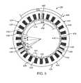
- FIG. 5is a plan view of an electromechanical machine having a segmented rotor design according to an embodiment of the present invention.
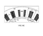
- FIGS. 6A-Care partial plan views of alternative embodiments of the present invention employing varying end tooth configurations.
- An electromechanical machine as referred to hereinis a machine for the generation of electrical energy from mechanical work, e.g., producing electricity from the rotation of turbine blades, or the conversion of electrical energy to mechanical work, e.g., the use of electricity to rotate an object.
- the present disclosureis directed to an apparatus and method including sectionalized stator and rotor designs, and for reducing cogging torque and torque ripple in an electromechanical machine.
- Embodiments of the inventionhave particular application to single tooth concentric wound devices, although it may be applicable to other designs as well.
- sectionalizing and segmentingare used in many ways in the art with respect to electromechanical machines. For example, they can refer to constructing a rotor or stator of a machine in a plurality of arched or curved sections that can be installed into a structural frame to create a stator or rotor.
- Sectionalizingmeans that the rotor or stator are provided in conceptual sections, or, in other words, that the stator or rotor have repeated arched design portions corresponding to each section, but may be generally unitary structures, i.e., the stator or rotor sections are not made from separate pieces.
- the sectionscan be formed as individual segments that are assembled to form a complete rotor or stator.
- Sectionalizing a machine in accordance with embodiments of the present inventioninvolves an analysis of the physical layout, e.g., position and numbers of stator and rotor poles, etc., and an electrical layout, e.g., the number of phases, number of circuits, and the coil arrangements, etc.
- the physical layoute.g., position and numbers of stator and rotor poles, etc.
- an electrical layoute.g., the number of phases, number of circuits, and the coil arrangements, etc.
- Poles on the stator and rotorare referred to, respectively, as stator poles and rotor poles.
- stator poles and rotor polesFor simplicity and clarity of description, the illustrative embodiments discussed herein have three phases on the stator and two phases on the rotor. Other combinations may be used in practice and still fall within the invention.
- the rotor phasesare north and south magnetic poles and the stator phases are single tooth, concentrically wound poles.
- magnets for the polesit may be practical to have just two phases, but in a rotor having wound poles there could be any number of phases. If the stator has wound poles, it is possible to have any number of phases as well.
- exemplary stator designsuse single coil, single tooth concentric wound poles. This also may be a desirable structure for many large machines. However, as will be appreciated by persons of ordinary skill in the art, it is possible to have a single pole formed from a number of teeth and a number of coils. In such a case, the concepts discussed for the present invention are the same, but the description and details are more complex. Thus, for simplicity we use the terms rotor pole and stator pole to refer to either a permanent magnet pole or a wound coil on a tooth on the rotor or stator, respectively. Persons of ordinary skill in the art will be able to apply the teaching of the present invention to even more complex designs.
- Certain aspects of the present inventionrelate to the spacing of the stator or rotor poles. For uniform application, spacing is measured between the pole center lines.
- the center of wound polesare at the center of the teeth around which the wire is wound.
- the center of the magnetic polesis at the center of the magnets.
- the centers of the poles of a machinewere generally equally spaced around the machine.
- aspects of the present inventioninclude a structure and method for using unequal spacing to lower torque ripple and cogging torque while minimizing the decrease in torque or power density resulting from the new arrangement.
- the design for a generatormay include, at step 14 , an initial determination of the basic configuration, such as the winding type, e.g., single tooth concentric wound, a number of phases, a desired voltage, and/or desired current for the power delivered.
- step 14may include an initial determination of the number of phases, a desired torque, or desired speed of the motor shaft. Other initial considerations may be taken into account as determined applicable by persons of ordinary skill in the art.
- a next step 16would be the selection of the number of poles on each the rotor and stator.
- a next step, step 18would be a determination of the sectional structure, such as the number of sections and arrangement of poles, including the number of poles per series string and number of sections and circuits.
- each poleis composed of coil wrapped around a core, frequently called a tooth, a plurality of the coils can be connected together in series to create a string. Each string is then connected in parallel to obtain the desired design result.
- each string of polesshould have the same number of poles and an equal number of end poles (poles at the end of a section) so that the strings share current properly.
- the width of the polesis another physical parameter that may also be set at this time.
- a determination of the number of conceptual sectionsmay be included in step 18 .
- the number of sections of either the rotor or the statoris a whole number multiple of the number of phases.
- the choice for the number of sectionsalso may be influenced, in part, by the needs of manufacturing and assembly.
- the number of stator phasesmay be twice the number of electrical phases.
- persons of ordinary skill in the artmay determine the number of sections based on their own applications and preferred parameters taking into account the teachings of the present invention.
- step 18may be broken down into a series of sub-steps for stator design as illustrated in FIG. 1A .
- step 18may be broken down into a series of sub-steps for stator design as illustrated in FIG. 1A .
- step 18may be broken down into a series of sub-steps for stator design as illustrated in FIG. 1A .
- step 18may be broken down into a series of sub-steps for stator design as illustrated in FIG. 1A .
- step 18may be broken down into a series of sub-steps for stator design as illustrated in FIG. 1A .
- three phase designsgenerally predominate, it is possible to design and use machines with any integer number of phases.
- the number of poles per section and the arrangement of the poles within the sectionsis selected with the following design requirements in mind: First, the number of poles per section should be an integer that is not a whole number multiple of the number of phases. Second, each series string of poles should have the same number of poles. Third, each series string of poles should include equal numbers of end poles.
- step 20the number of sections is set to an integer multiple of the number of phases.
- step 22the maximum number of circuits is set as follows: if the number of poles per section is an even number, set the maximum number of circuits as equal to twice the number of sections divided by the number of phases; alternatively, if the number of poles per section is an odd number, set the maximum number of circuits as half the above number. Then, in step 24 , the number of circuits is selected from the possible number of circuits, which are the factors of the maximum number of circuits. It will be appreciated by persons of ordinary skill in the art that the steps illustrated in FIG.
- 1Aare just one exemplary method for arriving at a workable arrangement of coils, sections and circuits, in the case that the characteristics of the end pole are different enough to cause possible imbalances in the phase or the circuit's currents, which in turn would cause complex torque ripple patterns. If the end pole characteristics are of no significance, then many other techniques may be employed for arriving at a workable arrangement without departing from the scope of the present invention as set forth in the appended claims.
- the polesmay be arranged as
- each letter A, B, or Crepresents a phase that is connected to each pole and each “
- the overall design processmay continue with step 26 .
- the ratio of the number of coils to the number of magnets(pole ratio) generates a characteristic torque ripple at one or more harmonic integer multiples of the fundamental frequency and a resultant cogging torque harmonic.
- the harmonic integer of the frequency that is to be eliminated or reducedis identified at step 26 .
- an electromechanical machinegenerates numerous harmonics of the characteristic torque ripple frequency, each of which has a varying amount of influence on machine operation.
- the chosen harmonic torque ripple frequency to be canceledwill generally be the one with the greatest influence on the operation of the machine, e.g., the dominant harmonic torque ripple frequency.
- Torque ripple and cogging torquemay then be reduced or eliminated by appropriate arrangement of the spacing of poles within sections and across the boundaries between adjacent sections in either the rotor or stator. In one embodiment of the invention, this can be accomplished at steps 30 and 34 based on only a small number of selected parameters: the number of poles, the number of phases, the number of sections and a balancing factor.
- Equation 1the pole pitch within each section is calculated in step 30 using Equation 1 as follows:
- balancing factor Xis selected to be in the range of about 0.45 to about 0.95. In another embodiment, balancing factor X is in the range of about 0.60 to about 0.90.
- the boundary pole pitch, the center to center distance between adjacent end poles across section divisions,is calculated according to Equation 2 based on the calculated section pole pitch as follows:
- the sections of either a rotor or stator, wound or permanent magnetmay be arranged to reduce or eliminate a selected torque ripple harmonic.
- the number of phaseswill be two—north and south.
- the polesare arranged within each section with their centers at the section pole pitch and the last pole at each end of the section spaced from the section edge by one-half the boundary pole pitch. Tooth/coil or magnet sizes as previously selected still apply with the only caveat being that they should not be so large as to overlap when spaced at the calculated section pole pitch.
- stator and stator sectionsare described in more detail below. If the stator or rotor are individual segments, the segments may then be assembled at step 42 . It will be appreciated by persons of ordinary skill in the art that the design process steps illustrated in FIGS. 1 and 1A need not be followed linearly as depicted. Steps may be looped or reordered as appropriate to a particular design or process.
- FIG. 2shows an exemplary embodiment in which electromechanical machine 100 has a sectionalized and segmented stator design according to the present invention.
- Electromechanical machine 100has, among other things, a rotor assembly 104 and a stator assembly 108 .
- the wound stator poles of the stator assemblyare arranged in sections 109 , wherein each section is an individual segment 124 A-C as described below.
- rotor assembly 104 and stator assembly 108have a common central axis and reside within a housing (not shown).
- stator assembly 104is rotated by a shaft 106 , or other mechanism known in the art, that is acted upon by an external force, e.g., the wind, or the rotor assembly may rotate the shaft by being acted upon by stator assembly 108 , e.g., by periodic excitement of the coils 136 .
- stator assembly 108remains stationary.
- Stator assembly 108includes a stator frame 120 , carrying plural stator segments 124 A-C that each include a stator back iron 128 and a plurality of inwardly directed teeth 132 (also sometimes called cores).
- Coils 136are wound on teeth 132 to provide wound poles 144 .
- End poles 146are located at the end of each section. In the case of wound poles 144 , an end space 148 is presented between the end coils on end poles 146 that represent a space where a skipped tooth or pole would have been disposed in a conventional design.
- Stator back iron 128may be fabricated out of materials known in the art, such as various metals, composites, or other materials with sufficient rigidity and electrical characteristics, with laminated or solid construction, to meet the desired design specifications.
- the teeth (cores)may be disposed on the back iron or fabricated as a unitary body with the back iron, and are also made of materials known in the art.
- Rotor assembly 104includes plural magnets 116 disposed at least about equally around the surface of rotor member 112 .
- Magnets 116are typically, although not necessarily, permanent magnets composed of materials known in the art, such as composite metals or rare earth magnets.
- Rotor member 112is generally annular and may be fabricated out of materials readily apparent to those skilled in the art such as various metals, composites, or other materials with sufficient rigidity to maintain the annular shape of rotor member 112 under rotational stress.
- the attachment of magnets 116 to rotor member 112may be accomplished by means well known in the art.
- stator polesmay be arranged according to Equation 1 above.
- the number of poles (P), in this case stator poles,is 24, the number of phases (Ph) is 3, the harmonic to be eliminated (H) is 6 and the number of sections (N) is 3.
- the section pole pitch (PPs) within each sectionis calculated to be 14.0625 mechanical degrees.
- the end poles 146are then spaced from the section ends 126 by a distance equal to one-half the boundary pole pitch (PPb), calculated according to Equation 2 above. Based on the above parameters, the boundary pole pitch is 21.5625 mechanical degrees, one-half of which is 10.78125 mechanical degrees. If the width of the teeth 132 is hypothetically selected at 7.0 degrees, the slot between teeth in each section would be 7.0625 degrees, and the space at the end of each section, to the outside of the end teeth would be 7.28125 mechanical degrees.
- the unoccupied end space 148 between windings at the ends of segments or sectionsmay or may not be occupied by unwound end teeth as discussed in more detail below.
- electromechanical machine 100indicates that stator assembly 108 with the previously specified components encircles rotor assembly 104 (described as an “inside rotating configuration”)
- stator assembly 108 with the previously specified componentsencircles rotor assembly 104
- other configurations of electromechanical machine 100would be readily apparent to those skilled in the art.
- the rotor assemblymay encircle the stator assembly (described as an “outside rotating configuration”), or the rotor assembly may include a plurality of cores and a plurality of coils as poles, while the stator assembly may include a plurality of magnets as poles.
- more than one rotor assembly/stator assemblymay be used in an electromechanical machine according to the invention, such as where rotor assemblies and stator assemblies exist in a stacked configuration (not shown).
- rotor assemblies and stator assembliesexist in a stacked configuration (not shown).
- Those skilled in the artwould readily appreciate that the embodiments and methodology taught herein are applicable to electromechanical machines utilizing multiple rotor assemblies and stator assemblies in various configurations.
- FIG. 2although only three segments are shown in FIG. 2 , as would be apparent to those skilled in the art, more or fewer segments are possible.
- machine 200includes a rotor assembly 204 with a rotor member 224 comprising plural sections 224 A and 224 B and a plurality of poles 216 disposed there around. In this example there are sixteen poles and two rotor sections. Although machine 200 shows two distinct rotor segments forming sections 224 A and 224 B, in other embodiments the rotor sections may be conceptual sections that form an undivided rotor member.
- Stator assembly 208may include a stator frame 220 , a stator back iron 228 , a plurality of teeth 232 and a plurality of coils 236 that surround teeth 232 to form stator poles 244 .
- Teeth 232generally, although not necessarily, extend radially toward the central axis of stator assembly 208 an amount sufficient to provide for coils 236 , but not so far as to interfere with the movement of rotor assembly 204 .
- the design and configuration of a machine consisting of sixteen rotor poles 216 and twenty-four stator poles 244may, if constructed by typical procedures used in the art, generate, as a predominant frequency, a sixth harmonic torque ripple frequency.
- the configuration of the rotor assemblyis modified in accordance with the exemplary methodology described above as follows.
- Equation 1the pole pitch in each section (PPs) is calculated to be 21.5625 mechanical degrees if the balancing factor X is set at 1.
- the boundary pole pitch (PPb)is calculated to be 29.0625 mechanical degrees.
- the centers of each pole at the end of each sectionare spaced at one-half the boundary pole pitch, or 14.53125 mechanical degrees from each section edge 226 .
- the magnet widthcorresponds to the width of the rotor poles.
- the distance between magnetsfollows from the section pole pitch. For example if the magnet width were selected as being 20 mechanical degrees, when spaced at a section pole pitch of 21.5625 mechanical degrees, the distance between magnets would be 1.5625 degrees.
- the exemplary machinemay be constructed and assembled as described at steps 38 and 42 of FIG. 1 .
- Electromechanical machine 300 as shown in FIG. 4illustrates a further alternative exemplary embodiment of the present invention in which stator assembly 308 is formed with sections 309 provided as individual segments.
- the design and configuration of stator assembly 308 and machine 300is similar to that of machine 100 , as machine 300 includes a rotor assembly 304 that may include a rotor member 312 and a plurality of magnets 316 .
- Stator assembly 308may include a stator frame 320 , and a plurality of stator segments 324 with a stator back iron 328 , a plurality of inwardly extending teeth 332 and a plurality of coils 336 .
- section ends 326also correspond to the physical ends of the segments.
- the basic structureis selected as a three-phase machine comprising eighteen separate stator segments 324 A-R (all segments not shown), each including ten poles for a total of 180 poles.
- Teeth 332are selected with a width of 1.0 degrees.
- Teeth 332 and coils 336are paired to form stator poles 344 .
- the space between end poles 346is occupied by unwound end teeth 348 , which are formed by two halves, one on each section/segment end 326 .
- each segment 324has end teeth 348 .
- end teeth 348 from neighboring segmentsmay combine to form a divided unwound, skip tooth.
- the spacing of end polesmay be initially determined dividing 360 electrical degrees by the identified harmonic integer corresponding to the frequency to be reduced, which results in the spacing being approximately equal to the torque ripple frequency wave length.
- the pole pitch on the statormay then be determined by subtracting the spacing, Ss, from the electrical degree span of the segment, i.e., angular measurement around the circumference of the machine in electrical degrees divided by the number of segments, and then dividing that result by the number of poles in the segment.
- the pole pitch within each segmentcan alternatively be determined using Equation 4:
- FIG. 5shows a further alternative embodiment of machine 400 having a three stator pole to two rotor pole pole ratio, i.e., twenty-four coils to sixteen magnets.
- Machine 400includes a rotor assembly 404 with a rotor member 412 that supports magnets 416 .
- Stator assembly 408may include a stator frame 420 , and a plurality of stator sections 424 that include a stator back iron 428 , a plurality of teeth 432 and a plurality of coils 436 as previously described.
- sections 424are not formed as individual segments as the stator is a single piece construction. Teeth 432 and coils 436 are once again paired to form stator poles 442 .
- rotor poles 416normally would be spaced about equally around the circumference at, in this example, about 22.5 mechanical degrees (180 electrical degree) intervals.
- the twenty-four stator poles 442also would be typically spaced equally around the stator assembly 408 , at about 15.0 mechanical degree (120 electrical degree) intervals.
- skip teeth 440are added and sized using Equations 3-5 as described above. For example, if one desires to cancel the sixth harmonic frequency to the greatest extent and thus sets the balancing factor X as 1, spacing Ss will be 7.5 mechanical degrees.
- Pole pitch, PPwill thus be 14.0625 mechanical degrees and the slot width, D, between teeth will be 7.0625 degrees, assuming a tooth width, Wt, of 7.0 degrees.
- Skip teeth 440are disposed within the space between end poles 446 , but since the stator is of unitary construction, skip teeth 440 are also unitary.
- FIGS. 6A-CExemplary designs of skip teeth in this regard are shown in FIGS. 6A-C , illustrating three alternative embodiments each with magnets 516 , teeth 532 , coils 536 and back irons 528 .
- FIGS. 6A-CExemplary designs of skip teeth in this regard are shown in FIGS. 6A-C , illustrating three alternative embodiments each with magnets 516 , teeth 532 , coils 536 and back irons 528 .
- the leakage inductance of the end poleswill be somewhat higher than the other poles since the end slots are narrower than the others.
- the leakage inductanceis lower.
- an intermediate shapecan be chosen that will provide similar leakage inductance closer to the internal sector poles.
- FIG. 6Ashows a short skip tooth 540 A
- FIG. 6Bshows a tapered skip tooth 540 B
- FIG. 6Cshows a thin skip tooth 540 C.
- the rotor flux couplingcan generally be controlled by adjusting the amount of the skip tooth that is near the rotor and how far it is from the rotor.
- the exact shape and dimensions of the skip toothare functions of many generator design details and must be adjusted for each design. It will depend on choices of parameters such as the air gap between the rotor and stator, the tooth width, the slot width, and the desired performance at full or partial power as may be determined by a person of ordinary skill in the art (for a particular application) based on the teachings continued herein.
- skip teethmay be configured to employ features of each of the embodiments of FIGS. 6A-C .
- the skip teethmay be short skip teeth with a trapezoidal shape wherein the base is narrower than the available end space.
- the skipped teethmay have a depth from stator back iron 528 of about 125 mm as compared to the full depth of about 133 mm of wound teeth 532 (i.e.
- the end space area between coils 536 of the end polesmay be only approximately 68% filled by a skip tooth.
- the end space areamay be not more than 90% occupied by an unwound tooth.
- the end space areamay be between about 55% and about 80% filled by a skip tooth.
- the short skip toothmay have a depth of about 90% to about 98% of the wound teeth.
- the skipped teethmay be about 5-15 mm shorter than adjacent wound teeth.
- solid skip teeth as shown in FIGS. 6A-Cmay also be formed in parts when segmented designs are employed as illustrated, for example, by end teeth 348 in FIG. 4 .
- the skipped toothmay be added as a separate component.
Landscapes
- Engineering & Computer Science (AREA)
- Power Engineering (AREA)
- Manufacturing & Machinery (AREA)
- Iron Core Of Rotating Electric Machines (AREA)
- Permanent Magnet Type Synchronous Machine (AREA)
Abstract
Description
- PPs is the section pole pitch;
- P is the number of poles;
- Ph is the number of phases;
- H is the harmonic number to be eliminated;
- N is the number of sections; and
- X is a factor in the range of greater than zero to one.
- PPb is the boundary pole pitch;
- PPs is the section pole pitch;
- P is the number of poles; and
- N is the number sections.
Ss=X*720/(H*Pr) [Equation 3]
- Ss is the sector spacing in mechanical degrees for the stator (this parameter corresponds to the boundary pole pitch minus the sector pole pitch (PPb−PPs) as calculated above);
- H is the harmonic integer associated with the harmonic torque ripple frequency to be reduced or eliminated;
- Pr is the number of rotor poles; and
- X is a factor in the range of greater than zero to one.
As described above, balancing factor X may be applied to adjust the balance between cogging torque reduction and loss of torque density.
- PPs is the stator pole pitch within a sector in mechanical degrees;
- N is the number of sections;
- Ss is the sector spacing in mechanical degrees; and
- Ps is the number of poles per stator segment.
D=PP−Wt [Equation 5]
- PP is the stator pole pitch in mechanical degrees;
- Wt is the angular width of the stator tooth; and
- D is the angular distance between stator teeth, e.g. the slots of a stator core.
With the distance, D, determined, a person of ordinary skill in the art may construct the physical or conceptual sections with the determined pole pitch and distance between poles to at least substantially eliminate the selected torque ripple harmonic.
Claims (10)
Priority Applications (7)
| Application Number | Priority Date | Filing Date | Title |
|---|---|---|---|
| US13/240,731US8912704B2 (en) | 2010-09-23 | 2011-09-22 | Sectionalized electromechanical machines having low torque ripple and low cogging torque characteristics |
| PCT/US2011/052893WO2012040542A1 (en) | 2010-09-23 | 2011-09-23 | Sectionalized electrochemical machines having low torque ripple and low cogging torque characteristics |
| CN201180054715.XACN103210566B (en) | 2010-09-23 | 2011-09-23 | Segmented electromechanical machines with low torque ripple and low variable torque characteristics |
| CA2812209ACA2812209A1 (en) | 2010-09-23 | 2011-09-23 | Sectionalized electromechanical machines having low torque ripple and low cogging torque characteristics |
| EP11764444.3AEP2619880A1 (en) | 2010-09-23 | 2011-09-23 | Sectionalized electrochemical machines having low torque ripple and low cogging torque characteristics |
| BR112013006902ABR112013006902A2 (en) | 2010-09-23 | 2011-09-23 | electromechanical machine, segment of a rotor or stator in an electromechanical machine and method to reduce roughing torque ripple in an eketromechanical machine |
| US14/566,193US9812909B2 (en) | 2010-09-23 | 2014-12-10 | Sectionalized electromechanical machines having low torque ripple and low cogging torque characteristics |
Applications Claiming Priority (2)
| Application Number | Priority Date | Filing Date | Title |
|---|---|---|---|
| US38566010P | 2010-09-23 | 2010-09-23 | |
| US13/240,731US8912704B2 (en) | 2010-09-23 | 2011-09-22 | Sectionalized electromechanical machines having low torque ripple and low cogging torque characteristics |
Related Child Applications (1)
| Application Number | Title | Priority Date | Filing Date |
|---|---|---|---|
| US14/566,193DivisionUS9812909B2 (en) | 2010-09-23 | 2014-12-10 | Sectionalized electromechanical machines having low torque ripple and low cogging torque characteristics |
Publications (2)
| Publication Number | Publication Date |
|---|---|
| US20120074797A1 US20120074797A1 (en) | 2012-03-29 |
| US8912704B2true US8912704B2 (en) | 2014-12-16 |
Family
ID=44736100
Family Applications (2)
| Application Number | Title | Priority Date | Filing Date |
|---|---|---|---|
| US13/240,731Expired - Fee RelatedUS8912704B2 (en) | 2010-09-23 | 2011-09-22 | Sectionalized electromechanical machines having low torque ripple and low cogging torque characteristics |
| US14/566,193Expired - Fee RelatedUS9812909B2 (en) | 2010-09-23 | 2014-12-10 | Sectionalized electromechanical machines having low torque ripple and low cogging torque characteristics |
Family Applications After (1)
| Application Number | Title | Priority Date | Filing Date |
|---|---|---|---|
| US14/566,193Expired - Fee RelatedUS9812909B2 (en) | 2010-09-23 | 2014-12-10 | Sectionalized electromechanical machines having low torque ripple and low cogging torque characteristics |
Country Status (6)
| Country | Link |
|---|---|
| US (2) | US8912704B2 (en) |
| EP (1) | EP2619880A1 (en) |
| CN (1) | CN103210566B (en) |
| BR (1) | BR112013006902A2 (en) |
| CA (1) | CA2812209A1 (en) |
| WO (1) | WO2012040542A1 (en) |
Cited By (9)
| Publication number | Priority date | Publication date | Assignee | Title |
|---|---|---|---|---|
| US20140230235A1 (en)* | 2013-02-18 | 2014-08-21 | David Thomas Allen | Method and apparatus for removal and replacement of a wound stator core |
| US20140354388A1 (en)* | 2013-05-29 | 2014-12-04 | Snu R&Db Foundation | Omni-directional shear-horizontal wave magnetostrictive patch transducer and method of winding coil |
| US9281731B2 (en) | 2010-09-23 | 2016-03-08 | Northem Power Systems, Inc. | Method for maintaining a machine having a rotor and a stator |
| US9359994B2 (en) | 2010-09-23 | 2016-06-07 | Northern Power Systems, Inc. | Module-handling tool for installing/removing modules into/from an electromagnetic rotary machine having a modularized active portion |
| US9812909B2 (en) | 2010-09-23 | 2017-11-07 | Weg Electric Corp | Sectionalized electromechanical machines having low torque ripple and low cogging torque characteristics |
| US20190360465A1 (en)* | 2018-05-22 | 2019-11-28 | Christopher T. Moore | Vertical axis wind turbine apparatus and system |
| US20210328466A1 (en)* | 2012-02-03 | 2021-10-21 | Green Ray Technologies Llc | Electric Machines with Energizable and Non-Energizerable U-Shaped Stator Segments |
| US11177710B2 (en)* | 2016-05-11 | 2021-11-16 | Wobben Properties Gmbh | Synchronous generator of a gearless wind turbine and method for producing a synchronous generator, and use of form coils |
| US11431216B1 (en) | 2014-06-19 | 2022-08-30 | Turboroto, Inc. | Electric motor, generator and commutator system, device and method |
Families Citing this family (25)
| Publication number | Priority date | Publication date | Assignee | Title |
|---|---|---|---|---|
| US8789274B2 (en) | 2010-09-23 | 2014-07-29 | Northern Power Systems, Inc. | Method and system for servicing a horizontal-axis wind power unit |
| US8816546B2 (en) | 2010-09-23 | 2014-08-26 | Northern Power Systems, Inc. | Electromagnetic rotary machines having modular active-coil portions and modules for such machines |
| JP5940421B2 (en)* | 2012-09-25 | 2016-06-29 | 株式会社デンソー | Rotating electric machine stator |
| US10224767B2 (en)* | 2012-11-20 | 2019-03-05 | Jaguar Land Rover Limited | Electric machine and method of operation thereof |
| CN203312934U (en)* | 2013-05-16 | 2013-11-27 | 张嘉宏 | Motor stator with improved structure |
| DE102013222643A1 (en)* | 2013-11-07 | 2015-05-07 | Robert Bosch Gmbh | Flat package for the production of a stator |
| DE102014200947A1 (en)* | 2014-01-20 | 2015-08-06 | Wobben Properties Gmbh | Synchronous generator of a gearless wind turbine |
| US10270300B2 (en)* | 2015-04-08 | 2019-04-23 | Nidec Motor Corporation | Motor with sectioned stator |
| EP3104499A1 (en)* | 2015-06-12 | 2016-12-14 | Siemens Aktiengesellschaft | Armature of an electrical machine |
| AU2017305647B2 (en)* | 2016-08-03 | 2022-01-27 | Intelligent Electric Motor Solutions Pty Ltd | Electric machines |
| US10833541B2 (en)* | 2016-11-21 | 2020-11-10 | Unison Industries, Inc. | Tooth-wound stator assembly |
| FR3061370B1 (en)* | 2016-12-27 | 2022-05-13 | Francecol Tech | ELECTROMAGNETIC ASSEMBLY WITH POLYPHASE STRUCTURE |
| WO2018141579A1 (en) | 2017-02-02 | 2018-08-09 | Siemens Wind Power A/S | Segmented stator electrical machine |
| CN108880014B (en)* | 2018-05-29 | 2021-10-29 | 南方电机科技有限公司 | A stator, motor and automation equipment |
| EP3648306A1 (en) | 2018-10-30 | 2020-05-06 | Siemens Gamesa Renewable Energy A/S | Electrical machine having a segmented stator or rotor |
| EP3648305B1 (en) | 2018-10-30 | 2021-06-30 | Siemens Gamesa Renewable Energy A/S | Electrical machine with hybrid tooth design |
| CN120127852A (en)* | 2018-12-28 | 2025-06-10 | 福特全球技术公司 | Stator and motor for electric motor |
| GB2582941B (en)* | 2019-04-09 | 2023-08-02 | Centre Nat Rech Scient | A stator winding arrangement |
| GB2587186A (en)* | 2019-09-11 | 2021-03-24 | Rolls Royce Plc | Electric Machines |
| JP2022055707A (en)* | 2020-09-29 | 2022-04-08 | 本田技研工業株式会社 | Rotary electric machine |
| US11621623B2 (en)* | 2021-01-15 | 2023-04-04 | Lin Engineering, Inc. | 4-stator-pole step motor with passive inter-poles |
| PL247156B1 (en)* | 2021-03-25 | 2025-05-19 | Akademia Gorniczo Hutnicza Im Stanislawa Staszica W Krakowie | Electric hook-up machine |
| JP7693387B2 (en)* | 2021-05-17 | 2025-06-17 | 株式会社Subaru | Vehicle motor |
| CN116488366A (en)* | 2022-11-02 | 2023-07-25 | 重庆润通科技有限公司 | Three-phase permanent magnet generator stator core, stator, three-phase permanent magnet generator and generator set for direct current charging |
| WO2025151428A1 (en)* | 2024-01-10 | 2025-07-17 | Electric Torque Machines, Inc. | Electric rotational machine |
Citations (77)
| Publication number | Priority date | Publication date | Assignee | Title |
|---|---|---|---|---|
| CH75705A (en) | 1917-06-12 | 1917-09-01 | Westinghouse Sa | Advanced training in dynamo-electric machines |
| US2078668A (en) | 1935-11-29 | 1937-04-27 | Westinghouse Electric & Mfg Co | Low-loss dynamo-electric machine |
| US3708707A (en) | 1970-05-21 | 1973-01-02 | Bbc Brown Boveri & Cie | Frame and core-type dynamo-electric machine |
| JPS5351407A (en) | 1976-10-21 | 1978-05-10 | Toshiba Corp | Revolving electrical machinery |
| US4315171A (en) | 1977-05-23 | 1982-02-09 | Ernest Schaeffer | Step motors |
| US4424463A (en) | 1981-05-27 | 1984-01-03 | Musil J Donald | Apparatus for minimizing magnetic cogging in an electrical machine |
| DE3546226A1 (en) | 1984-12-28 | 1986-07-03 | Kumagaya Seimitsu Co. Ltd., Kumagaya, Saitama | ROTATING ELECTRICAL MACHINE |
| US4769567A (en) | 1986-06-23 | 1988-09-06 | Tamagawa Seiki Kabushiki Kaisha | Brushless DC motor with cogging reduction |
| JPH01231645A (en) | 1988-03-11 | 1989-09-14 | Yaskawa Electric Mfg Co Ltd | Multiphase permanent magnet synchronous machine |
| US4868438A (en)* | 1986-04-01 | 1989-09-19 | Nec Corporation | Three-phase induction motor |
| US4990809A (en) | 1987-04-27 | 1991-02-05 | The Superior Electric Company | Variable reluctance motor |
| JPH04289759A (en) | 1991-03-18 | 1992-10-14 | Matsushita Electric Ind Co Ltd | brushless motor |
| US5196751A (en) | 1989-04-28 | 1993-03-23 | Siemens Aktiengesellschaft | Large-diameter a.c. motor with joints in the stator |
| US5675196A (en) | 1995-11-20 | 1997-10-07 | Quantum Corporation | High speed ten pole/twelve slot D.C. brushless motor with minimized net radial force and low cogging torque |
| US5691589A (en) | 1995-06-30 | 1997-11-25 | Kaman Electromagnetics Corporation | Detachable magnet carrier for permanent magnet motor |
| US5844341A (en) | 1993-06-03 | 1998-12-01 | Aea Technology Plc | Electromagnetic machine with at least one pair of concentric rings having modularized magnets and yokes |
| DE19905748A1 (en) | 1998-02-12 | 1999-08-19 | Okuma Machinery Works Ltd | Permanent magnet motor |
| EP0938181A1 (en) | 1998-02-13 | 1999-08-25 | Siemens Aktiengesellschaft | A.C. motor |
| DE19920309A1 (en) | 1998-05-07 | 1999-11-25 | Okuma Machinery Works Ltd | Electric multi-phase AC motor |
| JPH11335074A (en) | 1998-05-29 | 1999-12-07 | Toshiba Plant Kensetsu Co Ltd | Jig for disassembly and assembly of generator |
| US6093984A (en)* | 1998-08-21 | 2000-07-25 | Kabushiki Kaisha Toshiba | Rotor for electric motor |
| WO2000060719A1 (en) | 1998-12-15 | 2000-10-12 | Bonus Energy A/S | Generator for a windmill, stator module for use in such a generator and use of such a generator |
| WO2001021956A1 (en) | 1999-09-24 | 2001-03-29 | Lagerwey Windturbine B.V. | Wind power generator |
| US6265804B1 (en)* | 1998-09-08 | 2001-07-24 | Kabushiki Kaisha Toshiba | Electric motor with split stator core and method of making the same |
| DE10027246C1 (en) | 2000-05-31 | 2001-10-31 | Mannesmann Sachs Ag | Electrical machine has axial cooling channels in first set of stator laminations coupled together via deflection elements provided via second set of stator laminations |
| US6321439B1 (en) | 1997-01-21 | 2001-11-27 | Siemens Westinghouse Power Corporation | Method for assembly of a stator in the field |
| US20020074887A1 (en) | 2000-12-20 | 2002-06-20 | Tadashi Takano | Permanent magnet type rotor and permanent magnet type rotary electrical machine |
| US20020163272A1 (en) | 1996-11-04 | 2002-11-07 | Bertil Larsson | Stator for a rotating electric machine and a method of manufacturing a stator |
| WO2004017497A1 (en) | 2002-07-26 | 2004-02-26 | W.B.T.-S.A. World Business Technology | Generator for use in wind turbines or water-powered wheels |
| US6717323B1 (en) | 2002-06-04 | 2004-04-06 | Wavecrest Laboratories, Llc | Rotary electric motor having a plurality of skewed stator poles and/or rotor poles |
| EP1422806A2 (en) | 2002-11-19 | 2004-05-26 | Fanuc Ltd | Electric motor |
| US6777850B2 (en) | 2001-03-28 | 2004-08-17 | Mitsubishi Denki Kabushiki Kaisha | Stator and stator core for a dynamoelectric machine and a method for manufacture thereof |
| EP1458080A1 (en) | 2001-12-20 | 2004-09-15 | Mitsubishi Denki Kabushiki Kaisha | Permanent magnet type dynamo-electric machine and wind power generation-use permanent magnet type synchronous generator |
| JP2004289919A (en) | 2003-03-20 | 2004-10-14 | Nsk Ltd | Permanent magnet motor |
| US6819016B2 (en) | 2002-07-18 | 2004-11-16 | Tm4 Inc. | Liquid cooling arrangement for electric machines |
| US6844656B1 (en) | 1999-02-10 | 2005-01-18 | Neg Micon Control Systems A/S | Electric multipole motor/generator with axial magnetic flux |
| EP1519040A1 (en) | 2003-09-29 | 2005-03-30 | General Electric Company | Method and apparatus to remotely control a wind turbine park |
| WO2005031159A1 (en) | 2003-09-26 | 2005-04-07 | Neg Micon A/S | Method of conducting service on a wind turbine using equipment mounted on the hub |
| US6891298B2 (en)* | 2002-08-28 | 2005-05-10 | Emerson Electric Co. | Interior permanent magnet machine with reduced magnet chattering |
| ES2233146A1 (en) | 2002-11-21 | 2005-06-01 | Manuel Torres Martinez | Multipolar alternator for wind turbine, has permanent magnets arranged between steel side plates that are attached to support, where support is made of non-magnetic material i.e. aluminum |
| JP2005210790A (en) | 2004-01-21 | 2005-08-04 | Honda Motor Co Ltd | Rotating electric machine |
| US6975051B2 (en) | 2001-03-27 | 2005-12-13 | Rexroth Indramat Gmbh | Cooled primary or secondary part of an electric motor |
| WO2006032969A2 (en) | 2004-09-20 | 2006-03-30 | High Technology Investments B.V. | Generator/electric motor, in particular for wind power plants, cable controlled plants or for hydraulic plants |
| WO2006045772A1 (en) | 2004-10-26 | 2006-05-04 | Siemens Aktiengesellschaft | Electrical machine |
| US20060131985A1 (en) | 2004-12-16 | 2006-06-22 | General Electric Company | Electrical machines and assemblies including a yokeless stator with modular lamination stacks |
| US7113899B2 (en) | 2001-05-01 | 2006-09-26 | General Electric Company | Method and system for designing an electric machine stator including keybars |
| US20060279160A1 (en)* | 2005-06-08 | 2006-12-14 | Denso Corporation | Rotary electric machine with a stator core made of magnetic steel sheets and the stator core thereof |
| US7183689B2 (en) | 2002-03-08 | 2007-02-27 | Ina Drives & Mechatronics Gmbh & Co. Ohg | Torque motor having a segment design |
| WO2008014584A1 (en) | 2006-08-04 | 2008-02-07 | Clean Current Power Systems Incorporated | Axial air gap machine having stator and rotor discs formed of multiple detachable segments |
| WO2008021401A2 (en) | 2006-08-16 | 2008-02-21 | Gary Dickes | Permanent magnet alternator with segmented construction |
| US20080115347A1 (en) | 2004-04-26 | 2008-05-22 | Siemens Power Generation, Inc. | Horizontal Assembly of Stator Core Using Keybar Extensions |
| WO2008069818A1 (en) | 2006-12-08 | 2008-06-12 | General Electric Company | Portable hub crane for wind turbine components |
| US20080197742A1 (en) | 2006-01-20 | 2008-08-21 | Siemens Aktiengesellschaft | Electrical Machine Having a Three-Phase Winding System |
| EP1988282A2 (en) | 2007-04-26 | 2008-11-05 | M. Torres Disenos Industriales, S.A. | High electricity production wind generator |
| US20090026858A1 (en) | 2006-02-06 | 2009-01-29 | Axel Knauff | Cooling device for an electrical machine, electrical machines having a cooling device such as this, core laminate and production method for such electrical machines |
| US20090091210A1 (en) | 2005-06-27 | 2009-04-09 | Siemens Aktiengesellschaft | Direct drive for large-scale drives |
| US20090129931A1 (en) | 2007-11-21 | 2009-05-21 | Siemens Aktiengesellschaft | Module of a nacelle of a wind turbine, nacelle of a wind turbine, wind turbineand method for the assembly of a nacelle of a wind turbine |
| JP2009131030A (en) | 2007-11-22 | 2009-06-11 | Tamagawa Seiki Co Ltd | Motor core structure |
| EP2072814A2 (en) | 2007-12-19 | 2009-06-24 | General Electric Company | Braking and positioning system for a wind turbine rotor |
| US20090172934A1 (en) | 2008-01-08 | 2009-07-09 | Waheed Tony Mall | Methods and systems for in-situ machine maintenance |
| WO2009112887A1 (en) | 2008-03-13 | 2009-09-17 | Tecsis Tecnologia E Sistemas Avançados Ltda | Method and apparatus for handling aerogenerator blades |
| US20090261668A1 (en) | 2008-04-18 | 2009-10-22 | Abb Oy | Cooling element for an electrical machine |
| EP2131475A2 (en) | 2008-06-02 | 2009-12-09 | Siemens Aktiengesellschaft | Rotor for an electric machine |
| WO2010024510A1 (en) | 2008-09-01 | 2010-03-04 | Doosan Heavy Industries & Construction Co., Ltd | Maintenance system for wind turbine equipment |
| EP2163528A1 (en) | 2008-09-12 | 2010-03-17 | Waltec Maschinen GmbH | Glass machine with direct drive |
| WO2010037392A2 (en) | 2008-09-30 | 2010-04-08 | Vestas Wind Systems A/S | A service crane for a wind turbine |
| EP2182570A1 (en) | 2008-10-28 | 2010-05-05 | Siemens Aktiengesellschaft | Arrangement for cooling of an electrical machine |
| EP2187506A1 (en) | 2008-11-13 | 2010-05-19 | Wilic S.Àr.L. | Wind power turbine for producing electric energy |
| DE102008063783A1 (en) | 2008-12-18 | 2010-06-24 | Wind-Direct Gmbh | Generator for a wind turbine and method for its production |
| EP2226502A1 (en) | 2009-03-03 | 2010-09-08 | Siemens Aktiengesellschaft | Method and arrangement to install a wind-turbine |
| WO2011031165A1 (en) | 2009-09-11 | 2011-03-17 | Blaaster Wind Technologies As | Wind turbine |
| EP2320080A1 (en) | 2009-11-06 | 2011-05-11 | Siemens Aktiengesellschaft | Arrangement for cooling of an electrical generator |
| US20110309712A1 (en)* | 2009-02-27 | 2011-12-22 | Robert Chin | Stator with intermediate teeth |
| US8083212B2 (en) | 2007-06-20 | 2011-12-27 | Mitsubishi Heavy Industries, Ltd. | Wind-turbine rotor-blade hoisting apparatus, method for attaching wind-turbine rotor blade, and method for constructing wind power generator |
| WO2012040542A1 (en) | 2010-09-23 | 2012-03-29 | Northern Power Systems, Inc. | Sectionalized electrochemical machines having low torque ripple and low cogging torque characteristics |
| WO2012040538A1 (en) | 2010-09-23 | 2012-03-29 | Northern Power Systems, Inc. | Module-handling tool for installing/removing modules into/from an electromagnetic rotary machine having a modularized active portion |
| WO2012040536A1 (en) | 2010-09-23 | 2012-03-29 | Northern Power Systems, Inc. | Method and system for maintaining a machine having a rotor and a stator |
Family Cites Families (10)
| Publication number | Priority date | Publication date | Assignee | Title |
|---|---|---|---|---|
| EP1217713B1 (en)* | 2000-12-20 | 2010-02-10 | Yamaha Motor Electronics Kabushiki Kaisha | Permanent magnet type rotor and permanent magnet type rotary electrical machine |
| DE10311674B4 (en) | 2003-03-11 | 2007-02-01 | aeroconcept Ingenieurgesellschaft für Luftfahrttechnik und Faserverbundtechnologie mbH | maintenance platform |
| DE102004044697B4 (en)* | 2004-09-15 | 2009-02-26 | Siemens Ag | synchronous machine |
| JP4626405B2 (en)* | 2005-06-01 | 2011-02-09 | 株式会社デンソー | Brushless motor |
| US8061999B2 (en) | 2008-11-21 | 2011-11-22 | General Electric Company | Spinner-less hub access and lifting system for a wind turbine |
| US8664819B2 (en) | 2009-08-18 | 2014-03-04 | Northern Power Systems Utility Scale, Inc. | Method and apparatus for permanent magnet attachment in an electromechanical machine |
| KR101124622B1 (en) | 2009-10-26 | 2012-03-19 | 한국생명공학연구원 | Activation method for Natural killer cell via regulating SOCS2 expression |
| CN101881758A (en) | 2010-06-25 | 2010-11-10 | 南开大学 | A method for measuring phthalates in atmospheric particles |
| US8816546B2 (en) | 2010-09-23 | 2014-08-26 | Northern Power Systems, Inc. | Electromagnetic rotary machines having modular active-coil portions and modules for such machines |
| US8789274B2 (en) | 2010-09-23 | 2014-07-29 | Northern Power Systems, Inc. | Method and system for servicing a horizontal-axis wind power unit |
- 2011
- 2011-09-22USUS13/240,731patent/US8912704B2/ennot_activeExpired - Fee Related
- 2011-09-23CNCN201180054715.XApatent/CN103210566B/ennot_activeExpired - Fee Related
- 2011-09-23EPEP11764444.3Apatent/EP2619880A1/ennot_activeWithdrawn
- 2011-09-23BRBR112013006902Apatent/BR112013006902A2/ennot_activeIP Right Cessation
- 2011-09-23WOPCT/US2011/052893patent/WO2012040542A1/enactiveApplication Filing
- 2011-09-23CACA2812209Apatent/CA2812209A1/ennot_activeAbandoned
- 2014
- 2014-12-10USUS14/566,193patent/US9812909B2/ennot_activeExpired - Fee Related
Patent Citations (81)
| Publication number | Priority date | Publication date | Assignee | Title |
|---|---|---|---|---|
| CH75705A (en) | 1917-06-12 | 1917-09-01 | Westinghouse Sa | Advanced training in dynamo-electric machines |
| US2078668A (en) | 1935-11-29 | 1937-04-27 | Westinghouse Electric & Mfg Co | Low-loss dynamo-electric machine |
| US3708707A (en) | 1970-05-21 | 1973-01-02 | Bbc Brown Boveri & Cie | Frame and core-type dynamo-electric machine |
| JPS5351407A (en) | 1976-10-21 | 1978-05-10 | Toshiba Corp | Revolving electrical machinery |
| US4315171A (en) | 1977-05-23 | 1982-02-09 | Ernest Schaeffer | Step motors |
| US4424463A (en) | 1981-05-27 | 1984-01-03 | Musil J Donald | Apparatus for minimizing magnetic cogging in an electrical machine |
| DE3546226A1 (en) | 1984-12-28 | 1986-07-03 | Kumagaya Seimitsu Co. Ltd., Kumagaya, Saitama | ROTATING ELECTRICAL MACHINE |
| US4868438A (en)* | 1986-04-01 | 1989-09-19 | Nec Corporation | Three-phase induction motor |
| US4769567A (en) | 1986-06-23 | 1988-09-06 | Tamagawa Seiki Kabushiki Kaisha | Brushless DC motor with cogging reduction |
| US4990809A (en) | 1987-04-27 | 1991-02-05 | The Superior Electric Company | Variable reluctance motor |
| JPH01231645A (en) | 1988-03-11 | 1989-09-14 | Yaskawa Electric Mfg Co Ltd | Multiphase permanent magnet synchronous machine |
| US5196751A (en) | 1989-04-28 | 1993-03-23 | Siemens Aktiengesellschaft | Large-diameter a.c. motor with joints in the stator |
| JPH04289759A (en) | 1991-03-18 | 1992-10-14 | Matsushita Electric Ind Co Ltd | brushless motor |
| US5844341A (en) | 1993-06-03 | 1998-12-01 | Aea Technology Plc | Electromagnetic machine with at least one pair of concentric rings having modularized magnets and yokes |
| US5691589A (en) | 1995-06-30 | 1997-11-25 | Kaman Electromagnetics Corporation | Detachable magnet carrier for permanent magnet motor |
| US5675196A (en) | 1995-11-20 | 1997-10-07 | Quantum Corporation | High speed ten pole/twelve slot D.C. brushless motor with minimized net radial force and low cogging torque |
| US20020163272A1 (en) | 1996-11-04 | 2002-11-07 | Bertil Larsson | Stator for a rotating electric machine and a method of manufacturing a stator |
| US6321439B1 (en) | 1997-01-21 | 2001-11-27 | Siemens Westinghouse Power Corporation | Method for assembly of a stator in the field |
| DE19905748A1 (en) | 1998-02-12 | 1999-08-19 | Okuma Machinery Works Ltd | Permanent magnet motor |
| EP0938181A1 (en) | 1998-02-13 | 1999-08-25 | Siemens Aktiengesellschaft | A.C. motor |
| DE19920309A1 (en) | 1998-05-07 | 1999-11-25 | Okuma Machinery Works Ltd | Electric multi-phase AC motor |
| JPH11335074A (en) | 1998-05-29 | 1999-12-07 | Toshiba Plant Kensetsu Co Ltd | Jig for disassembly and assembly of generator |
| US6093984A (en)* | 1998-08-21 | 2000-07-25 | Kabushiki Kaisha Toshiba | Rotor for electric motor |
| US6265804B1 (en)* | 1998-09-08 | 2001-07-24 | Kabushiki Kaisha Toshiba | Electric motor with split stator core and method of making the same |
| WO2000060719A1 (en) | 1998-12-15 | 2000-10-12 | Bonus Energy A/S | Generator for a windmill, stator module for use in such a generator and use of such a generator |
| US6781276B1 (en) | 1998-12-15 | 2004-08-24 | Bonus Enegy A/S | Generator for a windmill, stator module for use in such a generator and use of such a generator |
| US6844656B1 (en) | 1999-02-10 | 2005-01-18 | Neg Micon Control Systems A/S | Electric multipole motor/generator with axial magnetic flux |
| WO2001021956A1 (en) | 1999-09-24 | 2001-03-29 | Lagerwey Windturbine B.V. | Wind power generator |
| DE10027246C1 (en) | 2000-05-31 | 2001-10-31 | Mannesmann Sachs Ag | Electrical machine has axial cooling channels in first set of stator laminations coupled together via deflection elements provided via second set of stator laminations |
| US20020074887A1 (en) | 2000-12-20 | 2002-06-20 | Tadashi Takano | Permanent magnet type rotor and permanent magnet type rotary electrical machine |
| US6975051B2 (en) | 2001-03-27 | 2005-12-13 | Rexroth Indramat Gmbh | Cooled primary or secondary part of an electric motor |
| US6777850B2 (en) | 2001-03-28 | 2004-08-17 | Mitsubishi Denki Kabushiki Kaisha | Stator and stator core for a dynamoelectric machine and a method for manufacture thereof |
| US7113899B2 (en) | 2001-05-01 | 2006-09-26 | General Electric Company | Method and system for designing an electric machine stator including keybars |
| EP1458080A1 (en) | 2001-12-20 | 2004-09-15 | Mitsubishi Denki Kabushiki Kaisha | Permanent magnet type dynamo-electric machine and wind power generation-use permanent magnet type synchronous generator |
| US7183689B2 (en) | 2002-03-08 | 2007-02-27 | Ina Drives & Mechatronics Gmbh & Co. Ohg | Torque motor having a segment design |
| US6717323B1 (en) | 2002-06-04 | 2004-04-06 | Wavecrest Laboratories, Llc | Rotary electric motor having a plurality of skewed stator poles and/or rotor poles |
| US6819016B2 (en) | 2002-07-18 | 2004-11-16 | Tm4 Inc. | Liquid cooling arrangement for electric machines |
| WO2004017497A1 (en) | 2002-07-26 | 2004-02-26 | W.B.T.-S.A. World Business Technology | Generator for use in wind turbines or water-powered wheels |
| US6891298B2 (en)* | 2002-08-28 | 2005-05-10 | Emerson Electric Co. | Interior permanent magnet machine with reduced magnet chattering |
| EP1422806A2 (en) | 2002-11-19 | 2004-05-26 | Fanuc Ltd | Electric motor |
| ES2233146A1 (en) | 2002-11-21 | 2005-06-01 | Manuel Torres Martinez | Multipolar alternator for wind turbine, has permanent magnets arranged between steel side plates that are attached to support, where support is made of non-magnetic material i.e. aluminum |
| JP2004289919A (en) | 2003-03-20 | 2004-10-14 | Nsk Ltd | Permanent magnet motor |
| WO2005031159A1 (en) | 2003-09-26 | 2005-04-07 | Neg Micon A/S | Method of conducting service on a wind turbine using equipment mounted on the hub |
| EP1519040A1 (en) | 2003-09-29 | 2005-03-30 | General Electric Company | Method and apparatus to remotely control a wind turbine park |
| JP2005210790A (en) | 2004-01-21 | 2005-08-04 | Honda Motor Co Ltd | Rotating electric machine |
| US20080115347A1 (en) | 2004-04-26 | 2008-05-22 | Siemens Power Generation, Inc. | Horizontal Assembly of Stator Core Using Keybar Extensions |
| WO2006032969A2 (en) | 2004-09-20 | 2006-03-30 | High Technology Investments B.V. | Generator/electric motor, in particular for wind power plants, cable controlled plants or for hydraulic plants |
| US20080309189A1 (en) | 2004-09-20 | 2008-12-18 | High Technology Investments, B.V. | Generator/Electric Motor, in Particular for Wind Power Plants, Cable Controlled Plants or for Hydraulic Plants |
| WO2006045772A1 (en) | 2004-10-26 | 2006-05-04 | Siemens Aktiengesellschaft | Electrical machine |
| US20060131985A1 (en) | 2004-12-16 | 2006-06-22 | General Electric Company | Electrical machines and assemblies including a yokeless stator with modular lamination stacks |
| US20060279160A1 (en)* | 2005-06-08 | 2006-12-14 | Denso Corporation | Rotary electric machine with a stator core made of magnetic steel sheets and the stator core thereof |
| US20090091210A1 (en) | 2005-06-27 | 2009-04-09 | Siemens Aktiengesellschaft | Direct drive for large-scale drives |
| US20080197742A1 (en) | 2006-01-20 | 2008-08-21 | Siemens Aktiengesellschaft | Electrical Machine Having a Three-Phase Winding System |
| US7808136B2 (en) | 2006-02-06 | 2010-10-05 | Siemens Aktiengesellschaft | Cooling device for an electrical machine, electrical machines having a cooling device such as this, core laminate and production method for such electrical machines |
| US20090026858A1 (en) | 2006-02-06 | 2009-01-29 | Axel Knauff | Cooling device for an electrical machine, electrical machines having a cooling device such as this, core laminate and production method for such electrical machines |
| WO2008014584A1 (en) | 2006-08-04 | 2008-02-07 | Clean Current Power Systems Incorporated | Axial air gap machine having stator and rotor discs formed of multiple detachable segments |
| WO2008021401A2 (en) | 2006-08-16 | 2008-02-21 | Gary Dickes | Permanent magnet alternator with segmented construction |
| WO2008069818A1 (en) | 2006-12-08 | 2008-06-12 | General Electric Company | Portable hub crane for wind turbine components |
| EP1988282A2 (en) | 2007-04-26 | 2008-11-05 | M. Torres Disenos Industriales, S.A. | High electricity production wind generator |
| US8083212B2 (en) | 2007-06-20 | 2011-12-27 | Mitsubishi Heavy Industries, Ltd. | Wind-turbine rotor-blade hoisting apparatus, method for attaching wind-turbine rotor blade, and method for constructing wind power generator |
| US20090129931A1 (en) | 2007-11-21 | 2009-05-21 | Siemens Aktiengesellschaft | Module of a nacelle of a wind turbine, nacelle of a wind turbine, wind turbineand method for the assembly of a nacelle of a wind turbine |
| JP2009131030A (en) | 2007-11-22 | 2009-06-11 | Tamagawa Seiki Co Ltd | Motor core structure |
| EP2072814A2 (en) | 2007-12-19 | 2009-06-24 | General Electric Company | Braking and positioning system for a wind turbine rotor |
| US20090172934A1 (en) | 2008-01-08 | 2009-07-09 | Waheed Tony Mall | Methods and systems for in-situ machine maintenance |
| WO2009112887A1 (en) | 2008-03-13 | 2009-09-17 | Tecsis Tecnologia E Sistemas Avançados Ltda | Method and apparatus for handling aerogenerator blades |
| US20090261668A1 (en) | 2008-04-18 | 2009-10-22 | Abb Oy | Cooling element for an electrical machine |
| EP2131475A2 (en) | 2008-06-02 | 2009-12-09 | Siemens Aktiengesellschaft | Rotor for an electric machine |
| WO2010024510A1 (en) | 2008-09-01 | 2010-03-04 | Doosan Heavy Industries & Construction Co., Ltd | Maintenance system for wind turbine equipment |
| EP2163528A1 (en) | 2008-09-12 | 2010-03-17 | Waltec Maschinen GmbH | Glass machine with direct drive |
| WO2010037392A2 (en) | 2008-09-30 | 2010-04-08 | Vestas Wind Systems A/S | A service crane for a wind turbine |
| EP2182570A1 (en) | 2008-10-28 | 2010-05-05 | Siemens Aktiengesellschaft | Arrangement for cooling of an electrical machine |
| EP2187506A1 (en) | 2008-11-13 | 2010-05-19 | Wilic S.Àr.L. | Wind power turbine for producing electric energy |
| DE102008063783A1 (en) | 2008-12-18 | 2010-06-24 | Wind-Direct Gmbh | Generator for a wind turbine and method for its production |
| US20110309712A1 (en)* | 2009-02-27 | 2011-12-22 | Robert Chin | Stator with intermediate teeth |
| EP2226502A1 (en) | 2009-03-03 | 2010-09-08 | Siemens Aktiengesellschaft | Method and arrangement to install a wind-turbine |
| WO2011031165A1 (en) | 2009-09-11 | 2011-03-17 | Blaaster Wind Technologies As | Wind turbine |
| EP2320080A1 (en) | 2009-11-06 | 2011-05-11 | Siemens Aktiengesellschaft | Arrangement for cooling of an electrical generator |
| WO2012040542A1 (en) | 2010-09-23 | 2012-03-29 | Northern Power Systems, Inc. | Sectionalized electrochemical machines having low torque ripple and low cogging torque characteristics |
| WO2012040538A1 (en) | 2010-09-23 | 2012-03-29 | Northern Power Systems, Inc. | Module-handling tool for installing/removing modules into/from an electromagnetic rotary machine having a modularized active portion |
| US20120073118A1 (en) | 2010-09-23 | 2012-03-29 | Northern Power Systems, Inc. | Module-Handling Tool for Installing/Removing Modules Into/From an Electromagnetic Rotary Machine Having a Modularized Active Portion |
| WO2012040536A1 (en) | 2010-09-23 | 2012-03-29 | Northern Power Systems, Inc. | Method and system for maintaining a machine having a rotor and a stator |
Non-Patent Citations (25)
| Title |
|---|
| "Cogging Torque Minimization Technique for Multiple-Rotor, Axial-Flux, Surface-Mounted-PM Motors: Alternating Magnet Pole-Arcs in Facing Rotors," by Metin Aydin, Ronghai Qu, and Thomas A. Lipo, Industry Applications Conference, 38th IAS Annual Meeting, Oct. 12-16, 2003. |
| "Nature and Measurements of Torque Ripple of Permanent-Magnet Adjustable-Speed Motors," by John S. Hsu, Brian P. Scoggins, Matthew B. Scudiere, et al., Industry Applications Convference, 1995, 30th IAS Annual Meeting, Oct. 8-12, 1995. |
| Bianchi, N. et al., "Design Techniques for Reducing the Cogging Torque in Surface-Mounted PM Motors," IEEE Transactions on Industry Applications, Sep./Oct. 2002, 1259-1265, vol. 38, No. 5. |
| J.R. Hendershot Jr., Design of Brushless Permanent-Magnet Motors, Magna Physics Publishing and Clarendon Press Oxford 1994, pp. 10, 12 and 13.* |
| Notice of Allowance dated Apr. 25, 2014, in related U.S. Appl. No. 13/240,768, filed Sep. 22, 2011. |
| Notice of Allowance dated Mar. 28, 2014, in related U.S. Appl. No. 13/240,756, filed Sep. 22, 2011. |
| Office Action dated Dec. 19, 2013, in related U.S. Appl. No. 13/240,756, filed Sep. 22, 2011. |
| Office Action dated Jul. 29, 2014, in related U.S. Appl. No. 13/240,788, filed on Sep. 22, 2011. |
| Office Action dated Jun. 10, 2014, in related U.S. Appl. No. 13/240,779, filed Sep. 22, 2011. |
| Oxford English Dictionary, Definition of "integra," Mar. 17, 2013. |
| PCT International Search Report dated Sep. 23, 2012 for related PCT/US2011/052893 entitled "Sectionalized Electrochemical Machines Having Low Torque Ripple and Low Cogging Torque Characteristics," Petter et al. |
| RCE dated Oct. 25, 2013, in related U.S. Appl. No. 13/240,768, filed Sep. 22, 2011. |
| Response to Final Office Action dated Oct. 25, 2013, in related U.S. Appl. No. 13/240,768, filed Sep. 22, 2011. |
| Response to Office Action dated Mar. 19, 2014, in related U.S. Appl. No. 13/240,756, filed Sep. 22, 2011. |
| Response to Restriction Requirement dated Jul. 14, 2014, in related U.S. Appl. No. 13/240,788, filed on Sep. 22, 2011. |
| Response to Restriction Requirement dated May 12, 2014, in related U.S. Appl. No. 13/240,779, filed Sep. 22, 2011. |
| Restriction Requirement dated Mar. 11, 2014, in related U.S. Appl. No. 13/240,779, filed Sep. 22, 2011. |
| Restriction Requirement dated Mar. 13, 2014, in related U.S. Appl. No. 13/240,788, filed Sep. 22, 2011. |
| U.S. Appl. No. 13/240,756, filed Sep. 22, 2011. |
| U.S. Appl. No. 13/240,768, Aug. 6, 2013, Final Office Action. |
| U.S. Appl. No. 13/240,768, filed Sep. 22, 2011. |
| U.S. Appl. No. 13/240,768, Jun. 25, 2013, Response to Office Action. |
| U.S. Appl. No. 13/240,768, Mar. 15, 2013, Office Action. |
| U.S. Appl. No. 13/240,779, filed Sep. 22, 2011. |
| U.S. Appl. No. 13/240,788, filed Sep. 22, 2011. |
Cited By (14)
| Publication number | Priority date | Publication date | Assignee | Title |
|---|---|---|---|---|
| US9812909B2 (en) | 2010-09-23 | 2017-11-07 | Weg Electric Corp | Sectionalized electromechanical machines having low torque ripple and low cogging torque characteristics |
| US9281731B2 (en) | 2010-09-23 | 2016-03-08 | Northem Power Systems, Inc. | Method for maintaining a machine having a rotor and a stator |
| US9359994B2 (en) | 2010-09-23 | 2016-06-07 | Northern Power Systems, Inc. | Module-handling tool for installing/removing modules into/from an electromagnetic rotary machine having a modularized active portion |
| US20210328466A1 (en)* | 2012-02-03 | 2021-10-21 | Green Ray Technologies Llc | Electric Machines with Energizable and Non-Energizerable U-Shaped Stator Segments |
| US9190890B2 (en)* | 2013-02-18 | 2015-11-17 | Siemens Energy, Inc. | Method and apparatus for removal and replacement of a wound stator core |
| US20140230235A1 (en)* | 2013-02-18 | 2014-08-21 | David Thomas Allen | Method and apparatus for removal and replacement of a wound stator core |
| US9450169B2 (en)* | 2013-05-29 | 2016-09-20 | Snu R&Db Foundation | Omni-directional shear-horizontal wave magnetostrictive patch transducer and method of winding coil |
| US20140354388A1 (en)* | 2013-05-29 | 2014-12-04 | Snu R&Db Foundation | Omni-directional shear-horizontal wave magnetostrictive patch transducer and method of winding coil |
| US11431216B1 (en) | 2014-06-19 | 2022-08-30 | Turboroto, Inc. | Electric motor, generator and commutator system, device and method |
| US11735971B1 (en) | 2014-06-19 | 2023-08-22 | Turboroto, Inc. | Electric motor, generator and commutator system, device and method |
| US11177710B2 (en)* | 2016-05-11 | 2021-11-16 | Wobben Properties Gmbh | Synchronous generator of a gearless wind turbine and method for producing a synchronous generator, and use of form coils |
| US10724502B2 (en)* | 2018-05-22 | 2020-07-28 | Creating Moore, Llc | Vertical axis wind turbine apparatus and system |
| US11149715B2 (en) | 2018-05-22 | 2021-10-19 | Harmony Turbines Inc. | Vertical axis wind turbine apparatus and system |
| US20190360465A1 (en)* | 2018-05-22 | 2019-11-28 | Christopher T. Moore | Vertical axis wind turbine apparatus and system |
Also Published As
| Publication number | Publication date |
|---|---|
| US20120074797A1 (en) | 2012-03-29 |
| CN103210566A (en) | 2013-07-17 |
| WO2012040542A1 (en) | 2012-03-29 |
| US20150137652A1 (en) | 2015-05-21 |
| EP2619880A1 (en) | 2013-07-31 |
| BR112013006902A2 (en) | 2019-09-24 |
| US9812909B2 (en) | 2017-11-07 |
| CA2812209A1 (en) | 2012-03-29 |
| CN103210566B (en) | 2016-10-12 |
Similar Documents
| Publication | Publication Date | Title |
|---|---|---|
| US8912704B2 (en) | Sectionalized electromechanical machines having low torque ripple and low cogging torque characteristics | |
| JP4725684B1 (en) | Generator and wind power generation system | |
| JP5480962B2 (en) | Winding type rotor brushless double feeding motor | |
| US7982352B2 (en) | Electrical motor/generator having a number of stator pole cores being larger than a number of rotor pole shoes | |
| EP3648305B1 (en) | Electrical machine with hybrid tooth design | |
| US20110169363A1 (en) | Variable Speed Electric Motor/Generator | |
| US20180367005A1 (en) | Stator assembly with uneven conductors | |
| US10916981B2 (en) | Permanent magnet rotating device having minimized cogging torque, permanent magnet generator using same, and permanent magnet motor | |
| KR20160094250A (en) | Wind power generator as well as stator core and stator core module thereof | |
| CN102255406B (en) | There is generator and the wind turbine of compact single turn wave winding | |
| WO2018141579A1 (en) | Segmented stator electrical machine | |
| WO2014030246A1 (en) | Rotating electrical machine and wind generator system | |
| CA2584925C (en) | Electrical machines with reduced cogging | |
| CN110247488B (en) | Cooling of generator end windings | |
| US20110285142A1 (en) | Generator with Single Turn Wave Winding, Wind Turbine and Method for Determining the Thickness of the Slot Insulation of a Generator | |
| KR20150032790A (en) | Permanent magnet rotary electrical machine and wind-power generation system | |
| Cardoso et al. | Design of a wind turbines synchronous generator, with longitudinal excitation from permanent magnets | |
| Jiang et al. | Segmented permanent magnet synchronous machines for wind energy conversion system | |
| KR101905512B1 (en) | Permanent magnet single phase motor without starting device | |
| US20250246959A1 (en) | Multi-winding set fractional slot synchronous machine | |
| JP2017163796A (en) | Dynamo-electric machine | |
| RU2516246C2 (en) | Stator of rotating electric machine with constant excitation | |
| EP2388893A1 (en) | Generator with single turn wave winding and wind turbine | |
| EP3496233A1 (en) | Electric generator having end-windings with reduced axial protrusion |
Legal Events
| Date | Code | Title | Description |
|---|---|---|---|
| AS | Assignment | Owner name:NORTHERN POWER SYSTEMS, INC., VERMONT Free format text:ASSIGNMENT OF ASSIGNORS INTEREST;ASSIGNORS:PETTER, JEFFREY K.;HURTADO, HECTOR;REEL/FRAME:026951/0700 Effective date:20110922 | |
| AS | Assignment | Owner name:NORTHERN POWER SYSTEMS UTILITY SCALE, INC., VERMON Free format text:ASSIGNMENT OF ASSIGNORS INTEREST;ASSIGNOR:WIND POWER HOLDINGS, INC.;REEL/FRAME:027657/0598 Effective date:20120131 Owner name:WIND POWER HOLDINGS, INC., VERMONT Free format text:ASSIGNMENT OF ASSIGNORS INTEREST;ASSIGNOR:NORTHERN POWER SYSTEMS, INC.;REEL/FRAME:027657/0548 Effective date:20120131 | |
| AS | Assignment | Owner name:NORTHERN POWER SYSTEMS, INC., VERMONT Free format text:MERGER;ASSIGNOR:NORTHERN POWER SYSTEMS UTILITY SCALE, INC.;REEL/FRAME:032461/0921 Effective date:20131231 | |
| AS | Assignment | Owner name:WEG ELECTRIC CORP., GEORGIA Free format text:ASSIGNMENT OF ASSIGNORS INTEREST;ASSIGNOR:NORTHERN POWER SYSTEMS, INC.;REEL/FRAME:042293/0927 Effective date:20161026 | |
| FEPP | Fee payment procedure | Free format text:MAINTENANCE FEE REMINDER MAILED (ORIGINAL EVENT CODE: REM.) | |
| LAPS | Lapse for failure to pay maintenance fees | Free format text:PATENT EXPIRED FOR FAILURE TO PAY MAINTENANCE FEES (ORIGINAL EVENT CODE: EXP.); ENTITY STATUS OF PATENT OWNER: SMALL ENTITY | |
| STCH | Information on status: patent discontinuation | Free format text:PATENT EXPIRED DUE TO NONPAYMENT OF MAINTENANCE FEES UNDER 37 CFR 1.362 | |
| FP | Lapsed due to failure to pay maintenance fee | Effective date:20181216 |