US8911910B2 - Multi-mode charging of hierarchical anode - Google Patents
Multi-mode charging of hierarchical anodeDownload PDFInfo
- Publication number
- US8911910B2 US8911910B2US13/299,167US201113299167AUS8911910B2US 8911910 B2US8911910 B2US 8911910B2US 201113299167 AUS201113299167 AUS 201113299167AUS 8911910 B2US8911910 B2US 8911910B2
- Authority
- US
- United States
- Prior art keywords
- electrode
- fuel
- charging
- electrochemical cell
- bodies
- Prior art date
- Legal status (The legal status is an assumption and is not a legal conclusion. Google has not performed a legal analysis and makes no representation as to the accuracy of the status listed.)
- Active, expires
Links
Images


Classifications
- H—ELECTRICITY
- H01—ELECTRIC ELEMENTS
- H01M—PROCESSES OR MEANS, e.g. BATTERIES, FOR THE DIRECT CONVERSION OF CHEMICAL ENERGY INTO ELECTRICAL ENERGY
- H01M8/00—Fuel cells; Manufacture thereof
- H01M8/18—Regenerative fuel cells, e.g. redox flow batteries or secondary fuel cells
- H01M8/184—Regeneration by electrochemical means
- H—ELECTRICITY
- H01—ELECTRIC ELEMENTS
- H01M—PROCESSES OR MEANS, e.g. BATTERIES, FOR THE DIRECT CONVERSION OF CHEMICAL ENERGY INTO ELECTRICAL ENERGY
- H01M12/00—Hybrid cells; Manufacture thereof
- H01M12/04—Hybrid cells; Manufacture thereof composed of a half-cell of the fuel-cell type and of a half-cell of the primary-cell type
- H—ELECTRICITY
- H01—ELECTRIC ELEMENTS
- H01M—PROCESSES OR MEANS, e.g. BATTERIES, FOR THE DIRECT CONVERSION OF CHEMICAL ENERGY INTO ELECTRICAL ENERGY
- H01M8/00—Fuel cells; Manufacture thereof
- H01M8/06—Combination of fuel cells with means for production of reactants or for treatment of residues
- H01M8/0606—Combination of fuel cells with means for production of reactants or for treatment of residues with means for production of gaseous reactants
- H01M8/0656—Combination of fuel cells with means for production of reactants or for treatment of residues with means for production of gaseous reactants by electrochemical means
- Y—GENERAL TAGGING OF NEW TECHNOLOGICAL DEVELOPMENTS; GENERAL TAGGING OF CROSS-SECTIONAL TECHNOLOGIES SPANNING OVER SEVERAL SECTIONS OF THE IPC; TECHNICAL SUBJECTS COVERED BY FORMER USPC CROSS-REFERENCE ART COLLECTIONS [XRACs] AND DIGESTS
- Y02—TECHNOLOGIES OR APPLICATIONS FOR MITIGATION OR ADAPTATION AGAINST CLIMATE CHANGE
- Y02E—REDUCTION OF GREENHOUSE GAS [GHG] EMISSIONS, RELATED TO ENERGY GENERATION, TRANSMISSION OR DISTRIBUTION
- Y02E60/00—Enabling technologies; Technologies with a potential or indirect contribution to GHG emissions mitigation
- Y02E60/10—Energy storage using batteries
- Y—GENERAL TAGGING OF NEW TECHNOLOGICAL DEVELOPMENTS; GENERAL TAGGING OF CROSS-SECTIONAL TECHNOLOGIES SPANNING OVER SEVERAL SECTIONS OF THE IPC; TECHNICAL SUBJECTS COVERED BY FORMER USPC CROSS-REFERENCE ART COLLECTIONS [XRACs] AND DIGESTS
- Y02—TECHNOLOGIES OR APPLICATIONS FOR MITIGATION OR ADAPTATION AGAINST CLIMATE CHANGE
- Y02E—REDUCTION OF GREENHOUSE GAS [GHG] EMISSIONS, RELATED TO ENERGY GENERATION, TRANSMISSION OR DISTRIBUTION
- Y02E60/00—Enabling technologies; Technologies with a potential or indirect contribution to GHG emissions mitigation
- Y02E60/30—Hydrogen technology
- Y02E60/50—Fuel cells
- Y02E60/528—
- Y—GENERAL TAGGING OF NEW TECHNOLOGICAL DEVELOPMENTS; GENERAL TAGGING OF CROSS-SECTIONAL TECHNOLOGIES SPANNING OVER SEVERAL SECTIONS OF THE IPC; TECHNICAL SUBJECTS COVERED BY FORMER USPC CROSS-REFERENCE ART COLLECTIONS [XRACs] AND DIGESTS
- Y02—TECHNOLOGIES OR APPLICATIONS FOR MITIGATION OR ADAPTATION AGAINST CLIMATE CHANGE
- Y02P—CLIMATE CHANGE MITIGATION TECHNOLOGIES IN THE PRODUCTION OR PROCESSING OF GOODS
- Y02P70/00—Climate change mitigation technologies in the production process for final industrial or consumer products
- Y02P70/50—Manufacturing or production processes characterised by the final manufactured product
Definitions
- the present inventionrelates to a rechargeable electrochemical cell system.
- Electrochemical cellsare well known.
- An electrochemical cellincludes an anode or fuel electrode at which a fuel oxidation reaction takes place, a cathode or oxidant electrode at which an oxidant reduction reaction takes place, and an ionically conductive medium for supporting the transport of ions.
- the fuel electrodecomprises a plurality of scaffolded electrode bodies, on which metal fuel is reduced and electrodeposited.
- Electrochemical cell systemsmay comprise a plurality of electrochemical cells.
- the fuel electrode of the first cellmay be coupled to a first terminal
- the oxidant electrode of each cell within the cell systemmay be connected to the fuel electrode of the subsequent cell
- the oxidant electrode of the last cell in the seriesmay be connected to a second terminal.
- the present applicationendeavors to provide a more efficient and effective architecture for recharging and discharging electrochemical cells and electrochemical cell systems.
- an electrochemical cellincludes a fuel electrode comprising a series of permeable electrode bodies arranged in spaced apart relation, an oxidant electrode spaced apart from the fuel electrode, and a charging electrode selected from the group consisting of (a) the oxidant electrode, (b) a third electrode spaced from the fuel electrode and the oxidant electrode, and (c) a portion of the fuel electrode.
- the electrochemical cellfurther includes an ionically conductive medium contacting the electrodes, and a charge/discharge controller coupled to a plurality of the electrode bodies of the fuel electrode.
- the charge/discharge controlleris configured to apply an electrical current between the charging electrode and at least one of the permeable electrode bodies, with the charging electrode functioning as an anode and the at least one permeable electrode body functioning as a cathode, such that reducible metal fuel ions in the ionically conductive medium are reduced and electrodeposited as metal fuel in oxidizable form on the at least one permeable electrode body, so that said electrodeposition causes growth of the metal fuel among the permeable electrode bodies, with the electrodeposited metal fuel establishing an electrical connection between the permeable electrode bodies.
- the charge/discharge controlleris configured to selectively apply the electrical current to a different number of said permeable electrode bodies, each functioning as a cathode, based on at least one input parameter so as to adjust a rate and density of the growth of the electrodeposited metal fuel.
- a method of recharging an electrochemical cellincludes a fuel electrode comprising a series of permeable electrode bodies arranged in spaced apart relation, an oxidant electrode spaced apart from the fuel electrode, and a charging electrode selected from the group consisting of (a) the oxidant electrode, (b) a third electrode spaced from the fuel electrode and the oxidant electrode, and (c) a portion of the fuel electrode.
- the electrochemical cellfurther includes an ionically conductive medium contacting the electrodes, and a charge/discharge controller coupled to a plurality of the electrode bodies of the fuel electrode.
- the charge/discharge controlleris configured to apply an electrical current between the charging electrode and at least one of the permeable electrode bodies, with the charging electrode functioning as an anode, and the at least one permeable electrode body functioning as a cathode, such that reducible metal fuel ions in the ionically conductive medium are reduced and electrodeposited as metal fuel in oxidizable form on the at least one permeable electrode body, so that said electrodeposition causes growth of the metal fuel among the permeable electrode bodies with the electrodeposited metal fuel establishing an electrical connection between the permeable electrode bodies.
- the charge/discharge controlleris configured to selectively apply the electrical current to a different number of said permeable electrode bodies based on at least one input parameter so as to adjust a rate and density of the growth of the electrodeposited metal fuel.
- the methodincludes selecting, based on the at least one input parameter, between a higher density progressive growth mode and a higher rate growth mode.
- the methodfurther includes charging the electrochemical cell based on the selected one of the higher density progressive charge mode and the higher rate growth mode.
- said chargingcomprises applying the electrical current to a terminal one of the permeable electrode bodies, with the charging electrode functioning as the anode and the terminal electrode body functioning as the cathode, such that the reducible metal fuel ions are reduced and electrodeposited as metal fuel in oxidizable form on the terminal permeable electrode body.
- the electrodepositioncauses growth of the metal fuel among the permeable electrode bodies such that the electrodeposited metal fuel establishes an electrical connection between the terminal electrode body and each subsequent permeable electrode body with said reduction and deposition occurring on each subsequent permeable electrode body upon establishment of said electrical connection.
- said chargingcomprises applying the electrical current simultaneously to a plurality of said electrode bodies, with the charging electrode functioning as the anode and each of the plurality of electrode bodies functioning as cathodes, such that the reducible metal fuel ions are reduced and electrodeposited as metal fuel in oxidizable form on the terminal permeable electrode body, said electrodeposition causing growth of the metal fuel among the permeable electrode bodies.
- the methodfurther includes disconnecting the electrical current to discontinue the charging.
- FIG. 1illustrates a cross-sectional view of an electrochemical cell system that includes two electrochemical cells
- FIG. 2illustrates an exploded view of the electrochemical cell system of FIG. 1 ;
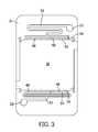
- FIG. 3illustrates an electrode holder of one of the electrochemical cells of FIG. 1 ;
- FIG. 4illustrates the electrode holder of FIG. 3 , holding a fuel electrode and a plurality of spacers connected to the electrode holder
- FIG. 5illustrates one of the spacers of FIG. 4 in greater detail
- FIG. 6illustrates a connection between the spacers of FIG. 5 and the electrode holder of FIG. 3 in greater detail
- FIG. 7schematically illustrates electrical connections between the electrochemical cell and an external load or power supply according to an embodiment of a cell system in accordance with the present invention
- FIG. 8schematically illustrates electrical connections between the electrochemical cell and an external load or power supply according to an embodiment of a cell system in accordance with the present invention
- FIG. 9schematically illustrates a switching system according to an embodiment of the cell system of FIG. 8 ;
- FIG. 10schematically illustrates a switching system according to another embodiment of the cell system of FIG. 8 ;
- FIG. 11schematically illustrates a switching system according to another embodiment of the cell system of FIG. 8 ;
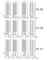
- FIGS. 12A-Cschematically illustrate the embodiments of FIGS. 9-11 further comprising a plurality of cells a switching system according to another embodiment of the cell of FIG. 8 ;
- FIG. 13schematically illustrates a switching system similar to the embodiment of FIG. 11 , further comprising a controller
- FIG. 14shows a flowchart illustrating an embodiment of a method of charging the cell, in accordance with the present invention
- FIG. 15shows a flowchart illustrating an embodiment of a method of discharging the cell
- FIG. 16schematically illustrates a switching system according to another embodiment of the cell of FIG. 8 ;
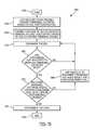
- FIG. 17shows a flowchart illustrating an embodiment of an algorithm for charging the cell, in accordance with the present invention.
- FIGS. 1 and 2illustrate an electrochemical cell system 100 that includes two electrochemical cells 10 according to an embodiment of the invention.
- each cell 10includes a fuel electrode 12 , and an oxidant electrode 14 that is spaced from the fuel electrode 12 .
- the fuel electrode 12supported by an electrode holder 16 .
- the electrochemical system 100also includes a cover 19 that is used to cover the electrochemical cells 10 on one side of the system 100 , while one of the electrode holders 16 is used to cover the opposite side of the system 100 , as illustrated in FIG. 1 .
- the fuel electrode 12is a metal fuel electrode that functions as an anode when the cell 10 operates in discharge, or electricity generating, mode, as discussed in further detail below.
- the fuel electrode 12may comprise a plurality of permeable electrode bodies 12 a - d , such as screens that are made of any formation able to capture and retain, through electrodepositing, or otherwise, particles or ions of metal fuel from an ionically conductive medium that circulates in the cell 10 , as discussed in further detail below.
- Components of the cell 10may be of any suitable construction or configuration, including but not limited to being constructed of Nickel or Nickel alloys (including Nickel-Cobalt, Nickel-Iron, Nickel-Copper (i.e. Monel), or superalloys), Copper or Copper alloys, brass, bronze, or any other suitable metal.
- a catalyst filmmay be applied to some or all of the permeable electrode bodies 12 a - d and/or the oxidant electrode 14 , and have a high surface material that may be made of some of the materials described above.
- the catalyst filmmay be formed by techniques such as thermal spray, plasma spray, electrodeposition, or any other particle coating method.
- the fuelmay be a metal, such as iron, zinc, aluminum, magnesium, or lithium.
- metalthis term is meant to encompass all elements regarded as metals on the periodic table, including but not limited to alkali metals, alkaline earth metals, lanthanides, actinides, and transition metals, either in atomic, molecular (including metal hydrides), or alloy form when collected on the electrode body.
- the fuelmay be provided to the cell 10 as particles suspended in the ionically conductive medium.
- a metal hydride fuelmay be utilized in cell 10 .
- the ionically conductive mediummay be an aqueous solution.
- suitable mediumsinclude aqueous solutions comprising sulfuric acid, phosphoric acid, triflic acid, nitric acid, potassium hydroxide, sodium hydroxide, sodium chloride, potassium nitrate, or lithium chloride.
- the mediummay also use a non-aqueous solvent or an ionic liquid.
- the mediumis aqueous potassium hydroxide.
- the ionically conductive mediummay comprise an electrolyte.
- a conventional liquid or semi-solid electrolyte solutionmay be used, or a room temperature ionic liquid may be used, as mentioned in U.S. patent application Ser. No.
- the fuelmay be oxidized at the fuel electrode 12 when the fuel electrode 12 is operating as an anode, and an oxidizer, such as oxygen, may be reduced at the oxidant electrode 14 when the oxidant electrode 14 is operating as a cathode, which is when the cell 10 is connected to a load L and the cell 10 is in discharge or electricity generation mode, as discussed in further detail below.
- the reactions that occur during discharge modemay generate by-product precipitates, e.g., a reducible fuel species, in the ionically conductive medium.
- zinc oxidemay be generated as a by-product precipitate/reducible fuel species.
- the oxidized zinc or other metalmay also be supported by, oxidized with or solvated in the electrolyte solution, without forming a precipitate (e.g. zincate may be a dissolved reducible fuel species remaining in the fuel).
- the reducible fuel speciese.g., zinc oxide
- the fuele.g., zinc
- either the oxidant electrode 14 or a separate charging electrode 70(which may be of similar construction or configuration as permeable electrode bodies 12 a - d in some embodiments), and/or another portion of the fuel electrode 12 , as described below, functions as the anode.
- the switching between discharge and recharge modesis discussed in further detail below.
- the electrode holder 16defines a cavity 18 in which the fuel electrode 12 is held.
- the electrode holder 16also defines an inlet 20 and an outlet 22 for the cell 10 .
- the inlet 20is configured to allow the ionically conductive medium to enter the cell 10 and/or recirculate through the cell 10 .
- the inlet 20may be connected to the cavity 18 via an inlet channel 24
- the outlet 22may be connected to the cavity 18 via an outlet channel 26 .
- the inlet channel 24 and the outlet channel 26may each provide a meandering tortuous path through which the ionically conductive medium may flow.
- the meandering path defined by the inlet channel 24preferably does not include any sharp corners in which the flow of the medium may become stagnated or in which any particulates in the medium may collect.
- the length of the channels 24 , 26may be designed to provide an increased ionic resistance between cells that are fluidly connected in series.
- a permeable seal member 17may be bonded between sealing surfaces on the electrode holders 16 and/or the cover 19 , as appropriate, to enclose at least the fuel electrode 12 in the cavity 18 .
- the seal member 17also covers the inlet and outlet channels 24 , 26 .
- the seal member 17is non-conductive and electrochemically inert, and is preferably designed to be permeable to the ionically conductive medium in the orthogonal direction (i.e., through its thickness), without permitting lateral transport of the ionically conductive medium.
- seal member 17This enables the ionically conductive medium to permeate through the seal member 17 for enabling ion conductivity with the oxidant electrode 14 on the opposing side to support the electrochemical reactions, without “wicking” the ionically conductive medium laterally outwardly from the cell 10 .
- a suitable material for the seal member 17are EPDM and TEFLON®.
- the cavity 18has a generally rectangular, or square, cross-section that substantially matches the shape of the fuel electrode 12 .
- the cavity 18may be connected to the inlet channel 24 by a plurality of inlets 34 so that when the ionically conductive medium and precipitates or reducible fuel species enter the cavity 18 , the ionically conductive medium and fuel are distributed along a side of the fuel electrode 12 .
- one side of the cavity 18specifically, the side of the cavity 18 that is connected to the inlet channel 24 , may include a plurality of fluidization zones, such as is described in U.S. patent application Ser. No. 12/901,410, incorporated herein in its entirety by reference.
- the ionically conductive mediummay enter the cavity 18 through a diffuser, such as is described in U.S. Provisional Patent Application No. 61/301,377, now converted into U.S. patent application Ser. No. 13/019,923 (published as U.S. Patent Application Publication No. 2011/0189551), each of which is also incorporated herein in its entirety by reference.
- the ionically conductive mediummay flow in parallel or in series through a plurality of cells 10 .
- the ionically conductive mediummay utilize a combination of parallel and series flows.
- the ionically conductive mediummay flow at a varying rate, and even may flow intermittently (i.e. static for a time) during operation of the one or more cells 10 .
- a plurality of spacers 40may be connected to the electrode holder 16 so that the fuel electrode 12 may be held in place relative to the electrode holder 16 and to the oxidant electrode 14 .
- the plurality of permeable electrode bodies 12 a - 12 dmay be separated by sets of the plurality of spacers 40 , so that each set of spacers 40 is positioned in between adjacent electrode bodies to electrically isolate the electrode bodies 12 a - 12 d from each other.
- the spacers 40are positioned in a spaced relation in a manner that creates so-called “flow lanes” 42 therebetween, as discussed in greater detail below.
- the flow lanes 42are three-dimensional and have a height that is substantially equal to the height of the spacers 40 .
- the spacers 40may be provided by a single frame that has cut-outs corresponding to the flow lanes.
- the flow lanes 42may include a foam or honeycomb-type structure that is configured to allow the ionically conductive medium to flow therethrough.
- the flow lanes 42may include an array of pins that are configured to disrupt the flow of the ionically conductive medium through the flow lanes.
- the frame, spacers 40 , flow lanes 42 , and/or other elements of cell 10may be defined by plastic formed by injection molding, or epoxy/insulating material formed using chemical processes. The illustrated embodiment is not intended to by limiting in any way.
- the spacers 40are non-conductive and electrochemically inert so they are inactive with regard to the electrochemical reactions in the cell 10 .
- the spacers 40are preferably sized so that when they are connected to the electrode holder 16 , the spacers 40 are in tension, which allows the spacers 40 to press against the fuel electrode 12 , or one of the electrode bodies 12 a - 12 c , so as to hold the fuel electrode 12 or bodies thereof in a flat relation relative to the electrode holder 16 .
- the spacers 40may be made from a plastic material, such as polypropylene, polyethylene, noryl, fluoropolymer, etc. that allows the spacers 40 to be connected to the electrode holder 16 in tension.
- the spacers 40may be attached together by techniques such as (but not limited to) thermal bonding, chemical bonding, or ultrasonic welding/bonding
- each spacerhas an elongated middle portion 44 , and a shaped connecting portion 46 at each end.
- the shaped connecting portions 46are configured to be held by openings 48 having substantially similar shapes in the electrode holder 16 , as illustrated in FIG. 6 .
- the shaped portions 46 and the openings 48have a substantially triangular shape, although the illustrated shape is not intended to be limiting in any way.
- the substantially triangular shapeprovides surfaces 50 on opposite sides of the elongated portion 44 of the spacer 40 that are configured to contact corresponding surfaces 52 on the electrode holder 16 .
- the surfaces 50 , 52are angled with respect to a major axis MA of the elongated portion 44 of the spacer 40 and the tension in the spacer 40 will be along the major axis MA, the forces created by the tension may be distributed across a larger surface, as compared to a shaped portion having a circular or square shape with the same area.
- the flow lanes 42are defined across the cavity 18 of the electrode holder 16 .
- the spacers 40are configured to essentially seal off one flow lane 42 a from an adjacent flow lane 42 b , that is separated by one of the spacers 40 so that the ionically conductive medium is guided to generally flow in substantially one direction.
- the ionically conductive mediummay generally flow in a first direction FD across the fuel electrode 12 , from the inlet channel 24 to the outlet channel 26 .
- a suitable pressure dropis generated between the inlet channel 24 and the inlets 34 so that the ionically conductive medium may flow across the cavity 18 and to the outlet channel 26 , even when the cell 10 is oriented such that the flow is substantially upward and against gravity.
- the ionically conductive mediummay also permeate through the fuel electrode 12 , or an individual permeable electrode body 12 a - 12 d , in a second direction SD and into a flow lane that is on the opposite side of the fuel electrode 12 or permeable electrode body 12 a - 12 d.
- the fuel electrode 12 of cell 10 in electrochemical cell system 100may be selectively connected to an external load L so that electrons given off by the fuel as the fuel is oxidized at the fuel electrode 12 may flow to the external load L.
- a switching system 60comprising a plurality of switches, may selectively electrically connect each of the individual permeable electrode bodies 12 a - 12 d of the fuel electrode 12 , and may also selectively connect the permeable electrode bodies 12 a - 12 d to the oxidant electrode 14 .
- electrochemical cell system 100may further comprise other cells 10 .
- the switching system 60may comprise a terminal selector system 62 configured to couple or decouple the external load L for use in discharging the cell 10 , or couple or decouple a power supply PS for use in charging the cell 10 .
- the switching system 60 and the terminal selector system 62may be separate, but may, in an embodiment, communicate with each other. The switching system 60 is discussed in greater detail below.
- the oxidant electrode 14functions as a cathode when the oxidant electrode 14 is connected to the external load L and the cell 10 operates in discharge mode. When functioning as a cathode, the oxidant electrode 14 is configured to receive electrons from the external load L and reduce an oxidizer that contacts the oxidant electrode 14 .
- the oxidizermay be any species of the oxidant available for oxidation at the charging electrode.
- the speciesmay be a free ion, or an ion bonded to or coordinated with other ions or constituents in the ionically conductive medium.
- the oxidant electrode 14comprises an air breathing electrode and the oxidizer comprises oxygen in the surrounding air.
- the oxidizermay be delivered to the oxidant electrode 14 by a passive transport system.
- a passive transport systemFor example, where oxygen present in ambient air is the oxidizer, simply exposing the oxidant electrode 14 to ambient air via openings in the cell, such as the openings that are provided by grooves 54 in the cover 19 and grooves 56 in the electrode holder 16 provided in the center of the electrochemical cell system 100 , may be sufficient to allow diffusion/permeation of oxygen into the oxidant electrode 14 .
- Other suitable oxidizersmay be used and embodiments described herein are not limited to the use of oxygen as the oxidizer.
- a peripheral gasket 15may be positioned between the periphery of the oxidant electrode 14 and the cover 19 or electrode holder 16 , as appropriate, to prevent the ionically conductive medium from leaking around the oxidant electrode 14 and into the area in the grooves 54 , 56 for air exposure.
- a pumpsuch as an air blower, may be used to deliver the oxidizer to the oxidant electrode 14 under pressure.
- the oxidizer sourcemay be a contained source of oxidizer.
- the oxygenmay be recycled from the cell 10 , such as is disclosed in U.S. patent application Ser. No. 12/549,617 (published as U.S. Patent Application Publication No. 2010/0119895), incorporated in its entirety herein by reference.
- the oxidizer sourcewhen the oxidizer is oxygen from ambient air, the oxidizer source may be broadly regarded as the delivery mechanism, whether it be passive or active (e.g., pumps, blowers, etc.), by which the air is permitted to flow to the oxidant electrode 14 .
- the term “oxidizer source”is intended to encompass both contained oxidizers and/or arrangements for passively or actively delivering oxygen from ambient air to the oxidant electrode 14 .
- Electricity that can be drawn by the external load Lis generated when the oxidizer at the oxidant electrode 14 is reduced, while the fuel at the fuel electrode 12 is oxidized to an oxidized form.
- the electrical potential of the cell 10is depleted once the fuel at the fuel electrode 12 is entirely oxidized or oxidation is arrested due to passivation of the fuel electrode.
- a portion of the switching system 60may be positioned in between the oxidant electrode 14 and the load L so that the oxidant electrode 14 may be connected and disconnected from the load L, as desired. Again, more details about the switching system 60 , and the electrical configuration thereof, is provided below.
- saltsmay be added to retard such a reaction.
- Salts of stannous, lead, copper, mercury, indium, bismuth, or any other material having a high hydrogen overpotentialmay be used.
- salts of tartrate, phosphate, citrate, succinate, ammonium or other hydrogen evolution suppressing additivesmay be added.
- metal fuel alloys, such as Al/Mgmay be used to suppress hydrogen evolution.
- Other additivesmay also or alternatively be added to the ionically conductive medium, including, but not limited to additives which enhance the electrodeposition process of the metal fuel on the fuel electrode 12 , such as is described in U.S.
- the power supply PSis configured to charge the cell 10 by applying a potential difference between the fuel electrode 12 and the oxidant electrode 14 such that the reducible species of the fuel is reduced and electrodeposited onto at least one of the permeable electrode bodies 12 a - 12 d and the corresponding oxidation reaction takes place at the oxidant electrode 14 , which is typically oxidation of an oxidizable species to evolve oxygen, which may be off-gassed from the cell 10 .
- oxygenis the oxidant
- oxygen ions in an aqueous electrolytic solutionare oxidized.
- the oxygen ionsmay be available from an oxide of the fuel (e.g., ZnO when zinc is the fuel), hydroxide ions (OH ⁇ ), or water molecules (H 2 O).
- the permeable electrode bodies 12 ais connected to the power supply PS so that the fuel reduces onto the permeable electrode body and progressively grows to and on the other permeable electrode bodies 12 b - 12 d , one by one.
- the switching system 60may control how the permeable electrode bodies 12 a - 12 d and the oxidant electrode 14 participate in the electrochemical reactions of the cell, as is described in greater detail below.
- FIG. 8shows an embodiment where a separate charging electrode 70 of cell 10 in electrochemical cell system 100 is provided to function as the charging electrode, rather than the oxidant electrode 14 .
- other cells 10may be part of electrochemical cell system 100 , as shown.
- the separate charging electrode 70may be positioned between the fuel electrode 12 and the oxidant electrode 14 , with a spacer 72 and the seal member 17 being positioned between the separate charging electrode 70 and the oxidant electrode 14 .
- the spacer 72is non-conductive and has openings through which the ionically conductive medium may flow.
- the oxidant electrode 14functions as the cathode during power generation/discharge, and as the anode during charging, as described above.
- the oxidant electrode 14remains the cathode during power generation/discharge, but may be disconnected during charging, while the separate charging electrode 70 is connected to the power supply PS to function as the anode.
- the fuel on the fuel electrode 12is oxidized, generating electrons that are conducted to power the load L and then conducted to the oxidant electrode 14 for reduction of the oxidizer (as discussed in more detail above).
- the switching system 60may control how the permeable electrode bodies 12 a - 12 d the oxidant electrode 14 , and the separate charging electrode 70 participate in the electrochemical reactions of the cell, as is described in greater detail below.
- any of the embodiments of the inventionit is also possible in any of the embodiments of the invention to apply the cathodic potential to any or all of the electrode bodies 12 a - 12 d of the fuel electrode 12 , rather than to just one to produce body-by-body progressive growth. Progressive growth emanating from one terminal is advantageous because it provides more density of the electrodeposited fuel. Specifically, the growth in the previously connected electrode bodies continues as each subsequent body is connected by the progressing growth. This and other advantages are discussed in greater detail in U.S. patent application Ser. No. 12/385,489, which has been incorporated herein by reference. With all the electrode bodies subject to the same potential, the growth will only occur until a short occurs between the charging electrode, which is the oxidant electrode 14 in the embodiment of FIG. 7 and the separate charging electrode 70 in the embodiment of FIG. 8 , and the electrode body proximate to it. Thus, it is possible to have a faster, but less dense, growth in this manner, which may be amenable to certain re-charging needs.
- FIGS. 7 and 8should not be considered to be limiting in any way and are provided as non-limiting examples of how the cell 10 may be configured to be rechargeable.
- the recharge mode of the present inventionin the context of the switching system 60 , is discussed in greater detail below.
- U.S. patent application Ser. No. 12/885,268published as U.S. Patent Application Publication No. 2011/0070506, filed on Sep. 17, 2010, the entire content of each of which is incorporated herein by reference, describes embodiments of a rechargeable electrochemical cell system with charge/discharge mode switching in the cells.
- the mediummay flow into the outlet channel 26 that is connected to the outlets 36 of the cavity 18 of the electrode holder 16 and the outlet 22 .
- the outlet 22may be connected to the inlet 20 in embodiments where the medium is recirculated in the cell 10 , or to an inlet of an adjacent cell, as discussed in further detail below, when a plurality of cells 10 are fluidly connected in series.
- the outlet 22may be connected to a vessel to collect the medium that has been used in the cell 10 .
- the flow of the ionically conductive mediummay vary, for example by flowing through a plurality of cells 10 in series or parallel, at a constant rate or a varying rate, continuously or intermittently.
- the cells 10 illustrated in FIGS. 1 and 2may be fluidly connected in series. Details of embodiments of cells that are connected in series are provided in U.S. patent application Ser. No. 12/631,484 (published as U.S. Patent Application Publication No. 2010/0316935), filed Dec. 4, 2009 and incorporated herein by reference in its entirety.
- the outlet 22 of a first cell 10may be fluidly connected to the inlet 20 of a second cell 10
- the outlet 22 of the second cell 10may be connected to the inlet 20 of a third cell, and so on.
- FIGS. 1 and 2illustrates two cells 10
- additional cellsmay be stacked and fluidly connected to the illustrated cells.
- the length of the flow passageways for the medium via the channels 24 , 26is greater than the distance between the fuel electrode 12 and the oxidant electrode 14 in each of the cells 10 . This creates an ionic resistance between the pair of fluidly connected cells that is greater than an ionic resistance within an individual cell 10 . This may reduce or minimize internal ionic resistance loss of the stack of cells 100 , as discussed in U.S. patent application Ser. No. 12/631,484.
- the fuel electrode 12which already has metal fuel deposited thereon, is connected to the load L and the oxidant electrode 14 is connected to the load L.
- the ionically conductive mediumenters the inlet 20 under positive pressure and flows through the inlet channel 24 , the inlets 34 of the cavity 18 , and into the flow lanes 42 .
- the ionically conductive mediumflows across the permeable electrode bodies 12 a - 12 d in the flow lanes 42 defined by the elongated middle portions 22 of the spacers 40 .
- the ionically conductive mediummay also permeate through the permeable electrode bodies 12 a - 12 d of the fuel electrode 12 .
- the ionically conductive mediumsimultaneously contacts the fuel electrode 12 and the oxidant electrode 14 , thereby allowing the fuel to oxidize and conduct electrons to the load L, while the oxidizer is reduced at the oxidant electrode 14 via the electrons that are conducted to the oxidant electrode 14 by the load L.
- the mediumflows out of the cavity 18 via the outlets 36 of the cavity 18 , through the outlet channel 24 , and out the outlet 22 of the cell 10 .
- the fuel electrode 12When the potential of the cell 10 has been depleted or when it is otherwise desirable to recharge the cell 10 , the fuel electrode 12 is connected to the negative terminal of the power supply PS and the charging electrode, which may be the oxidant electrode 14 or the separate charging electrode 70 , is connected to the positive terminal of the power supply PS. Such connections may again be through the switching system 60 , discussed below.
- the charging or recharge modea cathode portion of the fuel electrode 12 becomes the cathode and an anode portion of the fuel electrode 12 and/or the charging electrode 14 , 70 becomes the anode, as is described in greater detail below.
- fuel ionsmay reduce into fuel and redeposit onto the permeable electrode bodies 12 a - 12 d , as is described in greater detail below, while the ionically conductive medium circulates through the cell 10 in the same manner as described above with respect to the discharge mode.
- the flow lanes 42provide directionality and distribution of the ionically conductive medium across the fuel electrode 12 .
- the flow lanes 42may also prevent the particulates from settling and/or covering the electrodes.
- the improved distribution of the particulates across the fuel electrode 12allows for a more uniform deposition of the reduced fuel onto the fuel electrode 12 , which improves the density of the fuel on the fuel electrode 12 , and increases the capacity and energy density of the cell 10 , thereby enhancing the cycle-life of the cell 10 .
- by having the ability to control the distribution of the precipitates or reaction by-product during dischargeearly passivation/deposition of the by-product on the fuel electrode 12 may be prevented. Passivation leads to lower fuel utilization and lower cycle life, which is undesirable.
- FIGS. 1-8are not limiting, and are provided solely for context to understand general principles of an embodiment of the cells 10 of the cell system 100 . Any cell construction or configuration may be used. With an understanding of the cell system provided, attention is turned to the configuration and operation of the switching system 60 of the invention.
- a potential differenceis applied across electrodes in the cell 10 .
- an anodic potentialmay be applied to other electrodes, such as some of the electrode bodies in the fuel electrode 12 .
- a cathodic potentialmay be initially applied to electrode body 12 a of the fuel electrode 12 , but may also be initially applied to one or more of the other permeable electrode bodies 12 b - 12 d of the fuel electrode 12 .
- those permeable electrode bodies 12 a - 12 d of fuel electrode 12 having a cathodic potentialbehave as a cathode during charge, and serve as a reduction site for a reducible fuel species, such as the oxidized fuel ions created in the cell during discharging.
- the oxidant electrode 14 or the separate charging electrode 70 and/or those of the permeable electrode bodies 12 b - 12 d having the anodic potentialwill oxidize an oxidizable oxygen species, such as the reduced oxidant species created in the cell during discharging.
- an oxidizable oxygen speciessuch as the reduced oxidant species created in the cell during discharging.
- the reducible metal fuel speciesis being reduced and electrodeposited on some of the permeable electrode bodies 12 a - 12 d of the fuel electrode 12 , and the oxidizable oxygen species is being oxidized to oxygen gas, which may be off-gassed from the cell 10 .
- those electrodes and electrode bodies having an anodic potentialmay be considered an oxygen evolving electrode (OEE).
- electrical connections therebetweenmay be controlled by the switching system 60 , as is discussed in greater detail below.
- the fuel growthmay be advantageous to the fuel growth for the potential difference used to charge the cell 10 to be applied between adjacent bodies in the cell 10 , such that an electrode body having the anodic potential is adjacent to an electrode body having the cathodic potential.
- the electrode having the anodic potentialmay change, so that the permeable electrode body that previously was part of a set of electrode bodies having an anodic potential may become part of a set of electrode bodies having the cathodic potential.
- the application of the anodic potential from the power source to permeable electrode bodies 2 to N and the charging electrodemay comprise connecting all of the electrode bodies plus the charging electrode together at the same time, then disconnecting each of electrode bodies 2 to N in order.
- the application of the anodic potential from the power source to permeable electrode bodies 2 to N and the charging electrodecould comprise connecting and disconnecting each of the electrode bodies and the charging electrode individually in order (such that electrode body 2 is connecting to the anodic potential, then is disconnected and electrode 3 is connected to the anodic potential, and so on until the charging electrode is finally connected to complete the growth).
- the charging electrodemay merely be the last electrode to receive the anodic potential during charging.
- the charging electrodecould be the oxidant electrode or a separate electrode.
- the charging electrodeis a separate electrode, it could have a specialized construction different from the electrode bodies of the fuel electrode, or could be the same as the permeable electrode bodies (i.e. just one more electrode body), but for the fact that growth of the fuel during charging does not continue past it.
- the progressive changing of which electrode(s) have the anodic potentialmay follow the fuel growth through each of the permeable electrode bodies 12 a - 12 d , so that an electrode having an anodic potential remains the electrode body spaced adjacent to an electrode having the cathodic potential.
- the switch system 60may be configured to selectively connect and disconnect the various electrodes and electrode bodies to maintain the adjacent positions of the anodic potential and the cathodic potential.
- FIGS. 9-12show embodiments of the switching system 60 of the cell 10 .
- the cell 10is connectable to the power supply PS, the load L, or to other cells 10 in series, through a first terminal 130 and a second terminal 140 , wherein the first terminal 130 is negative (cathodic) during recharging, and the second terminal 140 is positive (anodic) during recharging.
- the cell 10has a fuel electrode 12 comprising permeable electrode bodies 12 a - 12 d , a charging electrode 70 , and an oxidant electrode 14 .
- the plurality of switchesmay selectively couple at least some of the permeable electrode bodies 12 b - 12 d to a power source, such as power supply PS, for application of an anodic potential during a recharging mode of the cell 10 , in which a cathodic potential is applied to at least electrode body 12 a , as will be described in greater detail below.
- a power sourcesuch as power supply PS
- the switching system 60includes a bypass switch 150 , configured to provide a direct connection between the first terminal 130 and the second terminal 140 .
- the bypass switch 150may be similar to that described in U.S. patent application Ser. No. 12/885,268, which has been incorporated herein in its entirety by reference.
- a cell 10can be bypassed with bypass switch 150 for a number of reasons that affect the performance of the stack.
- a short between charging electrode 70 and the electrode bodies 12 a - 12 d having a cathodic potential during chargemay lead to expense of parasitic power during charge.
- An electrical shortmay lead to a sudden drop in voltage between the charging and fuel electrodes as the current is shunted between the charging and fuel electrodes.
- Another exampleis during discharge, where any cell 10 that has a higher kinetic or ohmic loss affects the round trip efficiency and discharge power of the stack.
- consumption of fuel in the cell 10 during discharge earlier than other cells 10can lead to voltage reversal in the cell 10 and stack power loss, and can be prevented by bypassing the cell 10 when the discharge voltage falls below a critical value.
- the switching system 60 of FIG. 9also includes an oxidant electrode switch 160 associated with the oxidant electrode 14 .
- the oxidant electrode switch 160would be closed during discharge, so that an electric potential across the fuel electrode 12 and the oxidant electrode 14 may allow a current to be drawn by a load L connected between the first terminal 130 and the second terminal 140 , which during discharge would have positive and negative polarities respectively.
- a charging electrode switch 170may be associated with the charging electrode 70 , such that the charging electrode 70 may be electrically connected to the second terminal 140 when the power supply PS is connected between the first terminal 130 and the second terminal 140 .
- the charging electrode 70may not always have an anodic potential applied to it, and in an embodiment may only have an anodic potential when fuel growth between it and electrode body 12 d is desired.
- switches 180 , 190 , and 200associated with electrode bodies 12 b - 12 d respectively, all of which are configured to connect electrode bodies 12 b - 12 d to the second terminal 140 as well.
- an electrode having an anodic potentialbe adjacent to an electrode having a cathodic potential, so that growth on the electrode having the cathodic potential is enhanced.
- Such enhancementmay, for example, include greater density of fuel growth than if the electrode having the anodic potential is further from the closest electrode having the cathodic potential (i.e. if a neutral electrode separates the electrodes having the anodic and cathodic potentials).
- This enhanced densitymay be due to the initial dendrites that first contact the anodic body being disrupted because they lack sufficient cross-section to carry the current between the anodic and cathodic bodies. That is, they burn off similarly to a fuse element subject to excess current.
- Another advantagemay be lower electrolyte IR loss in configurations where the distance between the charging electrode 70 and the fuel electrode 12 is lower, as compared to configurations wherein the electrode having the anodic potential is further from the closest electrode having the cathodic potential (i.e. where neutral electrodes separate the electrodes having the anodic and cathodic potentials).
- This IR efficiency advantage resulting from less distance between anodic and cathodic electrodesmay be realized both in embodiments where metallic growth is occurring between the electrodes and in other embodiments, such as a metal hydride fuel where the hydrogen ions are being reduced.
- the cell 10 in the charging modewould be configured such that the bypass switch 150 is open, so that current does not bypass the cell 10 . Because the cell is in a charging mode, the oxidant electrode switch 160 is also open, so that the oxidant electrode 14 is electrically disconnected from the cell 10 . Since initially fuel growth is desired on electrode body 12 a , only electrode body 12 a is electrically connected to first terminal 130 , applying the cathodic potential thereto. To establish an anodic potential on the electrode body adjacent to electrode body 12 a , at least electrode body 12 b will be electrically connected to second terminal 140 .
- electrode bodies 12 c - 12 d , and charging electrode 70may also be electrically connected to second terminal 140 , and thus may also have the anodic potential. Because of the potential difference between the electrode(s) having the anodic potential (i.e. initially electrode body 12 a ) and the electrode(s) having the cathodic potential (i.e.
- reducible fuel species in the ionically conductive mediummay be reduced at the electrode having the initial cathodic potential (electrode body 12 a ) while cations in the ionically conductive medium are oxidized at electrode body 12 b (and any other body/electrode to which the anodic potential is applied).
- the switching system 60may disconnect the shorting electrode body that had the anodic potential, such that that electrode body has a cathodic potential applied to it, and a potential difference may be formed again between adjacent electrode bodies. This may require the further electrical connection of the adjacent electrode body to the second terminal 140 , if the electrical connection did not already exist, so as to create the anodic potential on that body. For example, in FIG.
- switch 180is opened so that both electrode body 12 a and, through the electric connection of the fuel growth, electrode body 12 b , have the cathodic potential.
- switch 190closes (if it was not already closed before), such that at least electrode body 12 c has an anodic potential, thus maintaining the adjacent electrode body separation for the potential difference between the electrode(s) having the cathodic potential and the electrode(s) having the anodic potential.
- the progressive shifting of which electrodes have the cathodic potential and which electrodes have the anodic potentialmay continue throughout the cell 10 , with the opening of switches 190 and 200 , until no further progression is desired or possible.
- the progressionwill end when the separate charging electrode 70 is the only electrode body having the anodic potential, and all permeable electrode bodies 12 a - 12 d of the fuel electrode 12 have the cathodic potential.
- Charging of the cell 10may subsequently end when fuel growth on electrode body 12 d causes an electrical connection between electrode body 12 d and charging electrode 70 .
- the switching system 70may be configured to have an over-charge configuration, wherein the cell may be configured to selectively apply a cathodic potential to charging electrode 70 by opening switch 170 , and closing switch 160 , applying the anodic potential to the oxidant electrode 14 , utilizing it for further charging of cell 10 by permitting fuel growth on the charging electrode 70 .
- Charging of the cell 10may in various embodiments progress from electrode body to electrode body among the plurality of permeable electrode bodies 12 a - 12 d , or may end based on criteria such as the voltage, current, slope of voltage, slope of current, charge capacity, or value of impedance or resistance. Such measurements in various embodiments may be taken over one or more of the electrode bodies 12 a - 12 d , or across one or more cells 10 . In an embodiment, charging may end based on a sensing electrode placed between the charging electrode and the last permeable electrode body 12 d of the fuel electrode 12 .
- oxidant electrode switch 160During discharge of the cell 10 in the embodiment of FIG. 9 , oxidant electrode switch 160 would be closed, while charging electrode switch 170 would be open. Additionally, switches 180 , 190 , and 200 would be open, and fuel consumption would be from electrode body 12 d to electrode body 12 a , wherein the electrical connection between the electrode bodies 12 a - 12 d are through the fuel growth. In the illustrated embodiment, this is so electrode bodies 12 a - 12 d are not shorted to the oxidant electrode 14 by oxidant electrode switch 160 .
- FIG. 10another embodiment of switching system 60 is illustrated for the cell 10 .
- the switching system 60also includes a series of connecting switches 210 a - d , configured to selectively and progressively connect each of the electrode bodies 12 b - d to either the first terminal 130 or the second terminal 140 , such that each of the electrode bodies 12 b - d either has a cathodic potential (i.e. is connected to at least electrode body 12 a ) or an anodic potential (i.e. is connected to at least charging electrode 70 ).
- bypass switch 150would be open so the cell is not bypassed.
- Oxidant electrode switch 160would also be open, so that oxidant electrode 14 is disconnected during the charging process.
- Charging electrode switch 170would be closed so that at least charging electrode 70 would have an anodic potential.
- switches 210 b , 201 c , and 210 dwould be closed, so that the anodic potential created through the electrical connection to second terminal 140 is applied through electrode bodies 12 b - 12 d , as well as charging electrode 70 .
- switch 210 bwould open, so that electrode bodies 12 a - 12 b have the cathodic potential, while electrode bodies 12 c - 12 d and charging electrode 70 have the anodic potential.
- switch 210 awould also be closed, so that a stronger electrical connection between electrode bodies 12 a - 12 b is formed, beyond the electrical connection of the fuel growth.
- Such progressioncould continue, as above, with the opening of switches 210 c and 210 d respectively, as the number of electrode bodies having the anodic potential shrinks, while the number of electrodes having the cathodic potential grows.
- switches 210 b and 210 ccould close in progression, to form a stronger electrical connection between electrode bodies 12 a - 12 d as the number of electrodes having a cathodic potential progressively grows.
- oxidant electrode switch 160would be closed, while charging electrode switch 170 would be open.
- switches 210 a - 210 dcould remain open and fuel consumption would be from electrode body 12 d to electrode body 12 a , wherein the electrical connection between the electrode bodies 12 a - 12 d are through the fuel growth.
- switches 210 a - 210 dcould be closed, so that an electrical connection is between all electrode bodies 12 a - 12 d of the fuel electrode 12 , and fuel is oxidized throughout the fuel electrode 12 while an oxidant is reduced at the oxidant electrode 14 . This is permissible in this embodiment because opening switch 170 also prevents the electrode bodies 12 a - d from being shorted to the oxidant electrode 14 by oxidant electrode switch 160 .
- the switching system 60comprises the bypass switch 150 , configured to selectively connect the first terminal 130 directly to the second terminal 140 , in order to bypass the cell 10 .
- the switching system 60 of the embodiment of FIG. 11also includes another series of connecting switches 220 a - d , configured to selectively connect each of the electrode bodies 12 a - d to the charging electrode 70 .
- the switching system 60may be configured to allow progressive change of those electrodes having the cathodic potential (i.e. at least electrode body 12 a ) and those electrodes having the anodic potential (i.e. at least charging electrode 70 ).
- bypass switch 150would be open so the cell is not bypassed.
- Oxidant electrode switch 160would also be open, so that oxidant electrode 14 is disconnected during the charging process.
- Charging electrode switch 170would be closed so that at least charging electrode 70 would have an anodic potential.
- Switch 220 awould be opened so that the cell is not bypassed from first terminal 130 to second terminal 140 through switch 220 a and switch 170 .
- At least switch 220 bwould be closed, so that at least electrode bodies 12 b , as well as charging electrode 70 , have the anodic potential.
- switch 220 bwould open, so that electrode bodies 12 a - 12 b have a cathodic potential (connected through the fuel growth).
- Switch 220 cwould then close, if it was not closed before, so that at least electrode body 12 c , as well as charging electrode 70 , would have the anodic potential.
- Such progressioncould continue, as above, with the opening of switches 210 c and 210 d respectively, as the number of electrode bodies having the anodic potential shrinks, while the number of electrode bodies having the cathodic potential grow.
- oxidant electrode switch 160would be closed, while charging electrode switch 170 would be open.
- switches 220 a - 220 dcould remain open and fuel consumption would be from electrode body 12 d to electrode body 12 a , wherein the electrical connection between the electrode bodies 12 a - 12 d are through the fuel growth therebetween.
- the progressive shifting of which electrode bodies have a cathodic potential versus which electrode bodies have an anodic potentialmay be analogized as the cell 10 having N electrode bodies defining two conceptual electrodes, a cathodic potential electrode and an anodic potential electrode.
- the constituent makeup of the cathodic potential electrodemay begin with a single electrode body, while the anodic potential electrode may comprise at least the adjacent electrode body, up to all other electrode bodies.
- fuelgrows on the cathodic potential electrode until, for example, no further growth on the electrode body is possible (i.e. the cathodic potential electrode has shorted to the anodic potential electrode).
- the electrode body of the anodic potential electrode that is adjacent to the cathodic potential electrodeis reassigned to become part of the cathodic potential electrode, through an electrical connection formed by the fuel growth and/or through the use of electrical circuitry or switches associated with the electrode bodies of the cell.
- the cathodic potential electrodenow comprises two electrode bodies, while the anodic potential electrode has one less than its initial number of electrode bodies.
- fuel growth from chargingmay resume, again until, for example, no further growth on the electrode bodies of the cathodic potential electrode is possible.
- the progressive shifting of the constituent makeup of the cathodic potential electrode and the anodic potential electrodemay continue throughout the cell, for example with the opening and/or closing of switches associated with the electrode bodies, until no further progression is desired or is possible. For example, once the anodic potential electrode comprises only a single electrode body, no further progression is possible.
- the charging of the cellmay subsequently end when fuel growth on the cell causes an electrical connection to form between the conceptual cathodic potential electrode and the conceptual anodic potential electrode that comprises only a single electrode body.
- charging of the cell 10may progress from electrode body to electrode body among the plurality of permeable electrode bodies 12 a - 12 d , or may end based on criteria such as the voltage, current, slope of voltage, slope of current, charge capacity, or value of impedance or resistance. Such measurements in various embodiments may be taken over one or more of the electrode bodies 12 a - 12 d , or across one or more cells 10 . In an embodiment, charging may end based on a sensing electrode placed between the charging electrode and the last permeable electrode body 12 d of the fuel electrode 12 .
- multiple electrochemical cells 10may be combined in cell system 100 .
- Shown in FIGS. 12A-Care electrochemical cell systems 100 of the embodiments of FIGS. 9-11 , however comprising N electrochemical cells 10 .
- the number Nis any integer greater than or equal to two, and is not limited to any particular number.
- the bypass switches 150 in the switching systems 60 of each cell 10are configured to selectively bypass each cell 10 by providing a direct connection between the first terminal 130 and the second terminal 140 . Such a connection may again be used to bypass defective cells 10 , or for any other reason.
- different embodiments of the switching system 60may be used in conjunction with one another in a single cell system 100 .
- the switches of the switching system 60may be of any type, and the term switch is broadly intended to describe any device capable of switching between the modes or states described.
- the switchesmay be single pole single throw or single pole double throw. They may be of the pivoting, sliding or latching relay type.
- semiconductor based switchesmay be used as well.
- the switchesmay be activated electrically (electromechanical relay) or magnetically or by other methods known to those familiar in the art. Any other suitable type of switch may be used, and the examples herein are not limiting.
- the plurality of switchesmay be connected in series if the switch has a leakage current in one direction.
- the body diode of a MOSFET semiconductor based switchwill conduct in one direction and the leakage current can be eliminated by placing MOSFET semiconductor based switches facing back to back in series.
- any suitable control mechanismmay be provided to control the action of switches in the switching system 60 and/or the terminal selector system 62 .
- the switches of the switching system 60may be controlled by a controller 230 .
- the controller 230may be of any construction and configuration.
- the controller 230may be configured to manage application of the anodic potential from the power supply PS to permeable electrode bodies 12 b - d and the charging electrode 70 .
- the controller 230may cause electrodeposition of metal fuel, through reduction of reducible ions of the metal fuel from the ionically conductive medium, to progressively grow from permeable electrode body 12 a to each subsequent electrode body 12 b - d for application of a cathodic potential to each subsequently connected electrode body 12 b - d .
- the controller 230may also cause removal of the anodic potential from each subsequently connected electrode body, and may cause application of the anodic potential to at least the subsequent electrode body unconnected by the electrodeposition, or the charging electrode where the last electrode body (i.e. electrode body 12 d ) has been electrically connected by the electrodeposition to the prior electrode bodies 12 a - c .
- Such application of the anodic potentialmay be configured to permit or cause oxidization of an oxidizable species of the oxidant.
- the controller 230may comprise hard-wired circuitry 232 that manipulates the switches based on an input 234 determining the proper switch configuration.
- the controller 230may also include a microprocessor for executing more complex decisions, as an option.
- the controller 230may also function to manage connectivity between the load L and the power source and the first and Nth cells (i.e. may control the terminal selector system 62 described above).
- the controller 230may include appropriate logic or circuitry for actuating the appropriate bypass switches 150 in response to detecting a voltage reaching a predetermined threshold (such as drop below a predetermined threshold).
- the controller 230may further comprise or be associated with a sensing device 236 , including but not limited to a voltmeter (digital or analog) or potentiometer or other voltage measuring device or devices, that can be used to determine when to modify the configuration of the plurality of switches, such as to maintain the proximity of the anode and the cathode as fuel growth progresses during charging.
- the sensing device 236may instead measure current, resistance, or any other electrical or physical property across or of the cell 10 that may be used to determine when to modify the configuration of the plurality of switches.
- the sensing device 236may measure a spike in current or a drop in potential difference between two electrode bodies.
- the controller 230may control the switches of the switching system 60 based on the passage of increments of time. For example, in an embodiment the time for fuel growth to progress between adjacent electrode bodies may be known, and used to calculate when to operate the switching system 60 so as to progressively rewire the electrodes to maintain an adjacent separation between the anode and the cathode. In an embodiment, the controller 230 may control the switches of switching system 60 to provide a high efficiency mode for the cell, such as is disclosed in U.S. Provisional Patent Application 61/323,384, now pending as U.S. patent application Ser. No. 13/083,929, each of which is incorporated in its entirety herein by reference.
- the controller 230may be configured to selectively enter different charging modes. For example, in one mode a plurality of electrode bodies may initially have an anodic potential, but the number decreases as the electrode bodies are given a cathodic potential. In another mode, only a single electrode body has an anodic potential at any given time, and the electrode body with the anodic potential changes as prior electrode bodies are given the cathodic potential. For example, in the former mode, the controller 230 may close all switches associated with the charging electrode 70 and electrode bodies 12 b - d during recharge, such that an anodic potential is applied to each of electrode bodies 12 b - d and the charging electrode 70 .
- the controller 230may then progressively open the switches associated with each of electrode bodies 12 b - d as the electrode bodies 12 b - d progressively become electrically connected to electrode body 12 a , and thus have a cathodic potential.
- the controllermay initially close only the switch associated with electrode body 12 b , giving electrode body 12 b an anodic potential while electrode body 12 a has a cathodic potential.
- the controller 230may open the switch associated with electrode body 12 b that gave electrode body 12 b the anodic potential, such that electrode body has a cathodic potential through its electrical connection to electrode body 12 a .
- the controller 230may then proceed to close the switch associated with electrode body 12 c , to provide electrode body 12 c with the anodic potential, again creating a potential difference, and the progression of fuel growth. These progressions of switch reassignments by the controller 230 may continue through or until only the charging electrode 70 has the anodic potential, as is described above.
- electrochemical cell 10comprises the fuel electrode 12 comprising the plurality of permeable electrode bodies 12 a - d . Although four permeable electrode bodies are listed, any number greater than or equal to two are possible.
- the cell 10further includes the oxidant electrode 14 , and the charging electrode, which may be the oxidant electrode 14 or the separate charging electrode 70 .
- the cell 10additionally includes the ionically conductive medium, and the switching system 60 comprising a plurality of switches, wherein at least some of the plurality of switches are associated with one of the permeable electrode bodies 12 a - d , the oxidant electrode 14 , and the charging electrode (i.e. oxidant electrode 14 or separate charging electrode 70 ).
- the switching system 60comprising a plurality of switches, wherein at least some of the plurality of switches are associated with one of the permeable electrode bodies 12 a - d , the oxidant electrode 14 , and the charging electrode (i.e. oxidant electrode 14 or separate charging electrode 70 ).
- reducible fuel ions in the ionically conductive mediumare reduced and electrodeposited as fuel in oxidizable form on a cathode comprising at least permeable electrode body 12 a while an oxidant is oxidized on an anode comprising at least an adjacent one of the permeable electrode bodies 12 b - d and/or the charging electrode (
- the method 240starts at 250 , and includes at 260 electrically connecting the cathode (i.e. in an embodiment, initially just permeable electrode body 12 a ), distal from the charging electrode, to the negative terminal of power supply PS, and the anode (i.e. initially at least permeable electrode body 12 b ) to the positive terminal of the power supply PS, creating a potential difference therebetween.
- the method 240continues at 270 , wherein, the fuel is electrodeposited on the cathode (i.e. at least permeable electrode body 12 a ).
- the method 240may continue by determining if fuel growth has progressed to beyond a threshold amount.
- the threshold amountmay be ascertained when the cell 10 is shorted by the fuel growth creating an electrical connection through the fuel growth between the cathode (i.e. permeable electrode body 12 a ) and the anode (i.e. permeable electrode body 12 b ). As shown, if fuel growth has not reached the threshold amount, the growth of fuel at 270 is repeated. Once the threshold amount is reached, the method continues at 290 , wherein it may be determined if further fuel growth is both possible and desired. In an embodiment, the determination at 290 may include ascertaining if there are additional electrode bodies, such as permeable electrode bodies 12 c - d , that fuel growth may be possible on.
- the methodcontinues at 300 by using the plurality of switches of the switching system 60 to disconnect the connecting electrode body (i.e. permeable electrode body 12 b ) from the anode, and if it were not connected through the switching system 60 before, connecting the next adjacent electrode body (i.e. permeable electrode body 12 c ) to the anode.
- the method 240then returns to 270 wherein fuel growth continues on the cathode. If no further fuel growth is possible or desired at 290 , the method 240 continues to 310 by disconnecting at least the negative terminal of the power source PS from the cell 10 to discontinue the charging process.
- the method 240may then end at 320 .
- FIG. 15another aspect of the present invention may include a method 330 for discharging the electrochemical cell 10 , which may be similar to that described above as related to FIG. 14 .
- fuel on permeable electrode bodies 12 a - 12 dis oxidized (and thus is consumed into the ionically conductive medium as reducible fuel ions), while an oxidizer is reduced at the oxidant electrode 14 .
- the method 330starts at 340 , and includes at 350 using the plurality of switches of the switching system 60 to connect the permeable electrode bodies 12 a - d that contain fuel.
- the plurality of switches of the switching system 60would be configured to electrically disconnect the separate charging electrode 70 (if present).
- the method 330would continue at 360 by electrically connecting the cathode (i.e. the air cathode, oxidant electrode 14 ) to the negative terminal of load L, and the anode (i.e.
- the method 330continues at 370 , wherein the fuel is consumed on the fuel electrode 12 .
- the plurality of switches 60connect the permeable electrode bodies 12 a - d , an anodic potential is applied to each of the permeable electrode bodies 12 a - d , and fuel may be consumed from each or any of permeable electrode bodies 12 a - d .
- the method 330may continue by determining if consumable fuel has been depleted from any permeable electrode body 12 a - d .
- a sensorsuch as the sensing device 236 above, which may include a current or a voltage sensor, may be present in the cell 10 , and may indicate when consumable fuel has been depleted from one or more of the permeable electrode bodies 12 a - d . If no depletion is detected, the discharging may continue as method 330 returns to step 370 . If, however, consumable fuel has been depleted from one or more of permeable electrode bodies 12 a - d , then method 330 may continue to step 390 , wherein it may be determined whether there are any remaining permeable electrode bodies 12 a - d that contain consumable fuel. This determination may be made simultaneously with the determination of depletion in step 380 , and may be made through a survey of sensing device(s) 236 , or by any other appropriate method.
- the method 330may continue at step 400 , wherein the switching system 60 adjusts the plurality of switches so that any of permeable electrode bodies 12 a - d that lack consumable fuel are disconnected from fuel electrode 12 .
- consumption of fuelmay initially be from the electrode body that is closest to the oxidant electrode 14 (such as, for example, permeable electrode body 12 d in the illustrated embodiments above), and switching system 60 may disconnect permeable electrode body 12 d , 12 c , and 12 b in that order, until all fuel is consumed from permeable electrode body 12 a .
- the methodmay continue to step 410 , wherein the load L may be disconnected.
- the load Lmay remain connected to the cell 10 when it is depleted, until the cell 10 is recharged, in which case it may be disconnected so that the cell 10 may be connected instead to the power supply PS.
- the method 330may then end at 420 .
- FIG. 16depicts another embodiment of the cell 10 .
- the embodiment of cell 10 in FIG. 16has the fuel electrode 12 with five electrode bodies 12 a - e .
- Cell 10further has a separate charging electrode 70 (i.e. a dedicated OEE), and an oxidant electrode 14 .
- cell 10includes a switching system 60 configured to selectively connect these electrodes and electrode bodies to one of the first terminal 130 or the second terminal 140 .
- the switching system 60may include the controller 230 , configured to control the plurality of switches connected to it through circuitry 232 .
- the controller 230may have the sensing device 236 included within it. Controller 230 may also receive instructions through the input 234 regarding how to control the switches.
- the cell 10may have the bypass switch 150 configured to connect first terminal 130 directly to second terminal 140 , bypassing the cell 10 in cases such as where a fault is present within the cell 10 , or for any other reason where utilization of the cell 10 is not desired.
- the oxidant electrode 14is again selectively connected to the second terminal 140 for discharging by oxidant electrode switch 160
- the separate charging electrode 70is again selectively connected to the second terminal 140 for charging by the charging electrode switch 170 .
- the electrode bodies 12 b - emay be selectively connected to either the first terminal 130 or the second terminal 140 by electrode body switches 425 b - e , where “b” through “e” indicate which of electrode bodies 12 b - e are associated with the respective switch.
- electrode body switches 425 b - eare configured to alternatively connect each of electrode bodies 12 b - e to either a first bus 427 a associated with electrode body 12 a (and thus first terminal 130 ), or a second bus 427 b associated with the separate charging electrode 70 (and thus second terminal 140 through charging electrode switch 170 ).
- electrode body switches 425 b - emay be characterized as Single Pole, Double Throw.
- electrode body switches 425 b - emay have three alternative settings, such that each electrode body 12 b - e may be electrically connected to electrode body 12 a (and first terminal 130 ), separate charging electrode 70 , or disconnected from both electrode body 12 a and separate charging electrode 70 .
- electrode body switches 425 b - emay be characterized as Single Pole, Triple Throw.
- Electrode bodies 12 b - emay be selectively coupled to the anode or the cathode in this embodiment, charging techniques such as but not limited to the progressive OEE described above, or that disclosed in U.S. Provisional Patent Application No. 61/383,510 and U.S. patent application Ser. No. 13/230,549, each of which is incorporated herein in its entirety by reference, may be utilized.
- the operation of electrode body switches 425 b - e in some embodimentsis discussed in greater detail below.
- another aspect of the present inventionmay include an algorithm 430 associated with different charge modes for the electrochemical cell 10 .
- the algorithm 430may be implemented onto any suitable embodiment of the electrochemical cell 10 by any appropriate mechanism.
- a more complex multiplexing switching system 60may be utilized.
- a plurality of Single Pole, Single Throw switchesmay be configured in an array to allow for electrical connection or isolation between any two or more of electrode bodies 12 a - e and separate charging electrode 70 . Any suitable system for electrically connecting electrode bodies 12 a - e and/or separate charging electrode 70 may be utilized.
- the algorithm 430may include instructions, such as computer interpretable or readable instructions, that may program or otherwise control the controller 230 .
- the algorithm 430may be located on a system that is networked with or otherwise connected to controller 230 .
- the algorithm 430may be stored on a medium within controller 230 , or within any other controller that may allow programmatic control of the switches in switching system 60 .
- algorithm 430may be configured, at 440 , to select a particular charge mode for the cell 10 .
- the selection of the charge modemay be made by any appropriate determination criteria 450 .
- the determination criteria 450may include measurements 460 of the cell 10 .
- the measurements 460 of the cell 10may be any appropriate measure of the status of the cell, including but not limited to sensor readings pertaining to the current status of fuel growth on permeable electrode bodies 12 a - e , readings of the current electrical connections formed by the switching system 60 , measurements of a voltage and/or current from or through the cell 10 , or so on.
- controller 230may utilize sensing device 236 , which in the current embodiment shows leads extending across the cell 10 , between first terminal 130 and second terminal 140 .
- Measurements 460may also include measures of the environment.
- measurements 460 of the environmentmay include ascertaining the current time. For example, where the cell 10 is associated with a solar power system, charging earlier in the day may utilize a different charge mode than charging when the sun is closer to setting.
- Other measurements 460 of the environmentare also possible.
- measurements 460may be of the environmental temperature, weather conditions, ambient light, movement of the cell 10 (i.e. if the cell 10 is utilized in a vehicle, different charge modes may be utilized for different speeds or braking styles), or so on.
- Determination criteria 450may also include manual overrides 470 , which may include any form of manual selection as to which charge mode is desired. Such a manual selection for manual overrides 470 may, in an embodiment, be provided to the controller 230 by input 234 .
- determination criteria 450may also include limits 480 , which for example may determine an appropriate charge mode based on exceeding predefined tolerances or settings.
- limits 480may be based on the measurements 460 , and include, for example, voltage difference between electrodes or electrode bodies, current impedance between electrodes or electrode bodies, or so on.
- limits 480may be based on voltage, current, slope of voltage, slope of current, charge capacity, or value of impedance or resistance, for example.
- Such limits 480may be based on measurements 460 on or across one or more electrode bodies 12 a - e , or on or across one or more cells 10 .
- the controller 230may identify the charge mode at 490 , and proceed to charge the cell 10 accordingly.
- the charge modemay be one which utilizes a progressive OEE, such as that described above, in the illustrated embodiment the controller 230 is configured to select from two alternative charge modes, a progressive charge mode 500 , and a parallel charge mode 600 .
- additional or alternative charge modesmay be utilized, and may be in accordance with the algorithm 430 .
- progressive charge mode 500is a high capacity charge mode.
- this high capacity charge modemay take a longer interval of time to complete the charging process, but may enable the greatest amount of energy storage within the cell 10 .
- Such a charging modemay be useful for a number of applications, including but not limited to emergency backup power and uninterruptible power supplies, where a larger amount of power may be needed, and a relatively large amount of time is available to recharge the cell 10 following its use. In such applications the amount of energy stored in cells 10 is of greater importance than the charging rate.
- the progressive charging mode 500may include five phases.
- the progressive charge mode 500may begin at a first phase 505 , wherein only the first electrode body 12 a forms the cathode, while electrode bodies 12 b - e and the separate charging electrode 70 form the charging electrodes.
- the first phase 505would have electrode body switches 425 b - e connecting electrode bodies 12 b - e to the separate charging electrode 70 through second bus 427 b , which would be connected to second terminal 140 through charging electrode switch 170 .
- only electrode body 12 awould be electrically connected to first terminal 130 , creating a potential difference between electrode body 12 a and the group of charging electrodes formed by the electrode bodies 12 b - e and the separate charging electrode 70 .
- Fuel growthwould then proceed on electrode body 12 a towards the adjacent electrode body 12 b.
- the progressive charge mode 500would proceed to a second phase at 515 , wherein electrode bodies 12 a - b form the cathode, while electrode bodies 12 c - e and the separate charging electrode 70 form the charging electrodes.
- the second phase 515would have electrode body switch 425 b disconnect electrode body 12 b from the group of charging electrodes on second bus 427 b , and electrically connect it to electrode body 12 a through first bus 427 a .
- the determination that electrode bodies 12 a - b have shorted at 510may be made through any suitable mechanism.
- the sensing device 236 associated with controller 230may measure a voltage drop or a current spike across the cell 10 .
- other sensing devices 236may ascertain the electrical connection, indicating the need to proceed to the second phase at 515 .
- the progressive charge mode 500may electrically disconnect the contacting electrode body 12 b - e from the second bus 427 b , and connect it instead to the first bus 427 a , progressively reassigning it form a charging electrode to a cathode.
- electrode body switches 425 b - eare Single Pole, Triple Throw
- the electrode body switches 425 b - emay either be configured to connect contacting electrode bodies 12 b - e along first bus 427 a , or the electrode body switches 425 b - e may move to their electrically disconnected position, such that their electrical connection to first terminal 130 is through the fuel growth alone. As depicted in the flowchart of FIG.
- progressive charge mode 500continues at 520 with determining the shorting of electrode bodies 12 b - c , before proceeding to a third phase at 525 , where electrode body 12 c would be disconnected from electrode body 12 d , such as by the throwing of electrode body switch 425 c .
- Fuel growthprogresses until the shorting between electrode bodies 12 c - d at 530 .
- a fourth phasewould begin at 535 , with electrode body 12 d being electrically disconnected from electrode body 12 e , such as by the throwing of electrode body switch 425 d , connecting electrode body 12 d with the first bus 427 a .
- the fuel growth progression to electrically short electrode bodies 12 d and 12 eis determined, and a fifth phase 545 begins, where electrode body 12 e is electrically disconnected from the separate charging electrode 70 , such as by the throwing of electrode body switch 425 e , connecting electrode body 12 e with the first bus 427 a , such that none of the charging electrodes 12 b - 3 are connected to the separate charging electrode 70 through the second bus 427 b.
- Electrode bodies 12 b - eare connected with electrode body 12 a , by the fuel growth through electrode bodies 12 a - e and/or electrical connections through the first bus 427 a , the fuel may continue to grow on electrode body 12 e towards the separate charging electrode 70 , due to the potential difference between those electrodes.
- a threshold capacitymay be defined so that the cell does not “over-charge.” For example, in some embodiments it may be undesirable that fuel growth reach and form an electrical connection to the separate charging electrode 70 .
- the threshold charge capacitymay be approximately 80-100% of the maximum possible charge capacity for the cell 10 .
- the measurement of capacitymay be made by any suitable mechanism, including in some embodiments taking measurements with the sensing device 236 , or computing or estimating a charge capacity through controller 230 . Regardless, once the threshold capacity has been reached, or electrode body 12 e has shorted with the separate charging electrode 70 , the cell may enter an idle state, to await a future discharge mode.
- the parallel charge mode 600may be selected at 490 .
- mini-cellsmay be formed within the cell 10 , with alternating bodies between electrode body 12 a and the separate charging electrode 70 acting as either an anode or a cathode.
- the parallel charge mode 600may be N times faster than progressive charge mode 500 (where N is the number of electrode bodies that metal fuel is being plated on).
- the growth rate on a given electrode bodyis limited by the diffusion-limited current density of the metal fuel deposition, which is affected by a number of factors, including viscosity, concentration, diffusity, and so on.
- the parallel charge mode 600would be faster than the progressive charge mode 500 , the fuel growth may be potentially less dense than in the progressive charge mode 500 , because the total charge deposited is limited by the time taken for electrical connections to form between all electrode bodies.
- the energy density held by the cell 10 charged by the parallel charge mode 600may be 1 ⁇ 4 to 1 ⁇ 2 that of the cell 10 charged by the progressive charge mode 500 .
- Some examples of applications that would prefer the parallel charge mode 600may include, for example, electric vehicles such as forklifts or cars, where a faster charge rate may be of greater importance than a larger charge density, like when the vehicle is being continuously used in close proximity to charging opportunities.
- the parallel charge mode 600may begin at a first phase 605 , with electrode bodies 12 a , 12 c , and 12 e connected to the first terminal 130 , while electrode bodies 12 b and 12 d , as well as the separate charging electrode 70 , are connected to the second terminal 140 .
- electrode body switches 425 c and 425 emay initially be controlled to connect electrode bodies 12 c and 12 e to the first bus 427 a .
- electrode body switches 425 b and 425 dmay be controlled to connect electrode bodies 12 b and 12 d to the second bus 427 b , where they are electrically connected to the second terminal 140 by charging electrode switch 170 , which is closed during charging.
- fuel growthmay be bi-directional on the intermediate electrode bodies 12 c and 12 e that are acting as cathodes.
- metal fuelis initially growing on electrode body 12 a towards electrode body 12 b , due to the potential difference therebetween.
- Fuelis also growing on electrode body 12 c both towards electrode body 12 b and towards electrode body 12 d Likewise, bidirectional fuel growth is occurring on electrode body 12 e , towards both electrode body 12 d and the separate charging electrode 70 .
- theremay be, at 610 , a number of continuity tests.
- N electrode bodiesthere may be N ⁇ 1 continuity tests performed to determine if an electrical connection has formed between any of the anodes and any of the cathodes. For example, at 610 a , it may be determined if electrode body 12 a has shorted to electrode body 12 b Likewise, at 610 b , it may be determined if an intermediate electrode body (i.e. electrode body 12 c - d in the illustrated embodiment) has shorted with either of the electrode bodies adjacent to it. Additionally, at 610 c , it may be determined if the last electrode body (i.e. the “N ⁇ 1” th electrode, which is electrode body 12 e in FIG. 16 ) has shorted with the separate charging electrode 70 .
- the last electrode bodyi.e. the “N ⁇ 1” th electrode, which is electrode body 12 e in FIG. 16
- the parallel charge mode 600may progress to an iterative next phase at 615 , wherein any shorted charging electrode (i.e. electrode body 12 b or electrode body 12 d ) is electrically disconnected from the second terminal 140 .
- any shorted charging electrodei.e. electrode body 12 b or electrode body 12 d
- any of the intermediate electrode bodies 12 b - emay be reassigned from acting as anodes to acting as cathodes, or vice versa, based on the electrical connections formed during the parallel charge mode 600 .
- the controller 230may assign the pair of fuel-linked electrode bodies 12 c - d to act together as a charging electrode, in that both electrode body switches 425 c - d connect electrode bodies 12 c - d to second terminal 140 via second bus 427 b , so that bidirectional fuel growth of fuel on electrode body 12 e continues.
- electrode body 12 bwould be electrically disconnected from second bus 427 b , such that a potential difference exists between electrode bodies 12 a - b and electrode bodies 12 c - d , so that additional fuel growth can occur on electrode bodies 12 a - b (as a cathode) towards electrode bodies 12 c - d (as a charging electrode).
- controller 230may then throw electrode body switch 425 e to electrically disconnect electrode body 425 e from first bus 427 a , such that electrode body 12 e and the separate charging electrode 70 , as well as the metal fuel therebetween, all act as an interconnected charging electrode. If electrode body 12 d is then reassigned as a cathode (due to electrical connection with electrode body 12 c , for example), then fuel growth may continue from electrode body 12 d toward electrode body 12 e , due to the potential difference therebetween.
- the reassignment of electrode bodies 12 b - dmay progress, measured by the continuity tests at 610 , until, at 620 , either all electrode bodies 12 a - e and the separate charging electrode 70 have shorted, or a threshold capacity for the cell 10 has been reached.
- the reaching of the threshold capacitymay be ascertained by any suitable mechanism, including in some embodiments taking measurements with the sensing device 236 , or computing or estimating a charge capacity through controller 230 .
- the cellmay end the parallel charge mode 600 and enter an idle state, to await a future discharge mode.
- the controller 230may be configured to charge the cell 10 such that some of the electrode bodies 12 a - e are charging in accordance with progressive charge mode 500 , while others of electrode bodies 12 a - e are charging in accordance with parallel charge mode 600 .
- the varying desires of charge rate and energy densitymay be implemented in the charge mode selection at 440 throughout the charging of the cell 10 , such that the real time needs of the application utilizing the cell 10 may be taken into account.
- the controller 230may measure typical discharge characteristics of the cell 10 over time, and modify the selection of the charge mode at 440 accordingly.
- the controller 230may utilize the parallel charge mode 600 to quickly charge the vehicle as needed during the daylight, however may utilize the progressive charge mode at night, so that the greater amount of stored energy is held by the cell 10 for use the following day.
- the controller 230may be more sophisticated, and may compute a more complex optimal energy vs. charge rate, to provide the optimal quantity of run time based on the usage of the cell 10 .
- the controller 230may also be configured to discharge the cell 10 in a variety of modes.
- the algorithm 430may be further configured to select between a charging mode and a discharging mode.
- a separate discharging algorithmmay be provided for the discharge mode or modes.
- differing modes of charging and discharging the cell 10may be managed by a broader “cell operations” algorithm, which may be run on controller 230 , for example.
- only the oxidant electrode 14 and a distal electrode bodyi.e. permeable electrode body 12 a
- are electrically connected to the load Lsuch that only the fuel electrically connects the permeable electrode bodies 12 a - e .
- the fuelDuring discharge, the fuel would progressively be consumed from electrode body 12 e (proximal to the oxidant electrode 14 ), towards the distal electrode body 12 a . Once fuel is sufficiently consumed from each of the intermediate permeable electrode bodies 12 b - d , those bodies would electrically disconnect from the fuel electrode 12 connected to the load L.
- the switching system 60may be used to selectively connect the permeable electrode bodies 12 b - e to the load L.
- permeable electrode bodies 12 b - emay all be connected to the load L throughout the discharging of the cell 10 .
- control of which electrode bodies (i.e. permeable electrode bodies 12 b - e ) are electrically connected to the load Lmay be ascertained by the discharging algorithm, and may depend on a particular discharge mode.
- the determination to selectively connect or disconnect the permeable electrode bodies 12 b - e from the load Lmay be based on measurements, manual overrides, or limits, which may be similar to those of determination criteria 450 that are used to determine the charge mode at 440 described above.
- the decision to connect or disconnect one of the permeable electrode bodiesmay be based on criteria such as the voltage, current, slope of voltage, slope of current, charge capacity, or value of impedance or resistance.
- Such measurementsin various embodiments may be taken over one or more of the electrode bodies 12 a - 12 e , or across one or more cells 10 .
- sensorssuch as sensing device 236 associated with one or more of the electrode bodies 12 a - e and/or one or more of the cells 10 may be utilized to take the measurements.
- the sensing device 236may be, for example, a voltmeter (digital or analog), potentiometer, or other voltage measuring device or devices, which can be used to determine when to modify the configuration of the plurality of switches.
- the sensing device 236may instead measure current, resistance, or any other electrical or physical property across or of the cell 10 that may be used to determine when to modify the configuration of the plurality of switches.
- the controller 230may control the switches of the switching system 60 based on the passage of increments of time. For example, in an embodiment the time for fuel consumption between adjacent electrode bodies may be known, and used to calculate when to operate the switching system 60 so as to disconnect depleted ones of the electrode bodies 12 b - e.
Landscapes
- Engineering & Computer Science (AREA)
- Manufacturing & Machinery (AREA)
- Chemical & Material Sciences (AREA)
- Chemical Kinetics & Catalysis (AREA)
- Electrochemistry (AREA)
- General Chemical & Material Sciences (AREA)
- Life Sciences & Earth Sciences (AREA)
- Sustainable Development (AREA)
- Sustainable Energy (AREA)
- Hybrid Cells (AREA)
- Fuel Cell (AREA)
- Secondary Cells (AREA)
Abstract
Description
Claims (33)
Priority Applications (1)
| Application Number | Priority Date | Filing Date | Title |
|---|---|---|---|
| US13/299,167US8911910B2 (en) | 2010-11-17 | 2011-11-17 | Multi-mode charging of hierarchical anode |
Applications Claiming Priority (2)
| Application Number | Priority Date | Filing Date | Title |
|---|---|---|---|
| US41457910P | 2010-11-17 | 2010-11-17 | |
| US13/299,167US8911910B2 (en) | 2010-11-17 | 2011-11-17 | Multi-mode charging of hierarchical anode |
Publications (2)
| Publication Number | Publication Date |
|---|---|
| US20120139496A1 US20120139496A1 (en) | 2012-06-07 |
| US8911910B2true US8911910B2 (en) | 2014-12-16 |
Family
ID=45923583
Family Applications (1)
| Application Number | Title | Priority Date | Filing Date |
|---|---|---|---|
| US13/299,167Active2033-07-12US8911910B2 (en) | 2010-11-17 | 2011-11-17 | Multi-mode charging of hierarchical anode |
Country Status (7)
| Country | Link |
|---|---|
| US (1) | US8911910B2 (en) |
| JP (1) | JP5908251B2 (en) |
| CN (1) | CN202695667U (en) |
| AU (1) | AU2011101611B4 (en) |
| BR (1) | BRPI1105606A2 (en) |
| DE (1) | DE202011051993U1 (en) |
| FR (1) | FR2967525B3 (en) |
Cited By (14)
| Publication number | Priority date | Publication date | Assignee | Title |
|---|---|---|---|---|
| WO2016149702A1 (en) | 2015-03-19 | 2016-09-22 | Fluidic, Inc. | Electrochemical cell comprising an electrodeposited fuel |
| WO2016160418A1 (en) | 2015-03-30 | 2016-10-06 | Fluidic, Inc. | Water management system in electrochemical cells with vapor return comprising air electrodes |
| US9484587B2 (en) | 2014-02-12 | 2016-11-01 | Fluidic, Inc. | Method of operating electrochemical cells comprising electrodeposited fuel |
| WO2018018037A1 (en) | 2016-07-22 | 2018-01-25 | Fluidic, Inc. | Mist elimination system for electrochemical cells |
| WO2018018036A1 (en) | 2016-07-22 | 2018-01-25 | Fluidic, Inc. | Moisture and carbon dioxide management system in electrochemical cells |
| WO2018191148A1 (en) | 2017-04-09 | 2018-10-18 | Nantenergy, Inc. | Fast switching back-up power supply system employing rechargeable electrochemical cells |
| US11552290B2 (en) | 2018-07-27 | 2023-01-10 | Form Energy, Inc. | Negative electrodes for electrochemical cells |
| US11611115B2 (en) | 2017-12-29 | 2023-03-21 | Form Energy, Inc. | Long life sealed alkaline secondary batteries |
| US12237548B2 (en) | 2018-06-29 | 2025-02-25 | Form Energy, Inc. | Stack of electric batteries including series of fluidly connected unit cells |
| US12261281B2 (en) | 2018-06-29 | 2025-03-25 | Form Energy, Inc. | Metal air electrochemical cell architecture |
| US12294086B2 (en) | 2019-07-26 | 2025-05-06 | Form Energy, Inc. | Low cost metal electrodes |
| US12308414B2 (en) | 2019-06-28 | 2025-05-20 | Form Energy, Inc. | Device architectures for metal-air batteries |
| US12381244B2 (en) | 2020-05-06 | 2025-08-05 | Form Energy, Inc. | Decoupled electrode electrochemical energy storage system |
| US12444755B2 (en) | 2024-02-08 | 2025-10-14 | Form Energy, Inc. | Corrugated fuel electrode |
Families Citing this family (24)
| Publication number | Priority date | Publication date | Assignee | Title |
|---|---|---|---|---|
| US7820321B2 (en) | 2008-07-07 | 2010-10-26 | Enervault Corporation | Redox flow battery system for distributed energy storage |
| US8785023B2 (en) | 2008-07-07 | 2014-07-22 | Enervault Corparation | Cascade redox flow battery systems |
| US8980484B2 (en) | 2011-03-29 | 2015-03-17 | Enervault Corporation | Monitoring electrolyte concentrations in redox flow battery systems |
| US8916281B2 (en) | 2011-03-29 | 2014-12-23 | Enervault Corporation | Rebalancing electrolytes in redox flow battery systems |
| US10326144B2 (en) | 2011-07-19 | 2019-06-18 | Nantenergy, Inc. | Hygrophobic conductor layer for electrochemical cell |
| US9214708B2 (en) | 2011-08-05 | 2015-12-15 | Fluidic, Inc. | Gas vent for electrochemical cell |
| US9444105B2 (en) | 2011-11-04 | 2016-09-13 | Fluidic, Inc. | Immersible gaseous oxidant cathode for electrochemical cell system |
| US9413048B2 (en) | 2011-11-04 | 2016-08-09 | Fluidic, Inc. | Air cathode with graphite bonding/barrier layer |
| CN203225320U (en) | 2011-11-04 | 2013-10-02 | 流体公司 | Electrochemical cell system |
| EP2909880B1 (en)* | 2012-10-18 | 2021-12-01 | NantEnergy, Inc. | Electrochemical cell with doping of metallic anodes |
| FR2998719B1 (en) | 2012-11-29 | 2016-05-06 | Electricite De France | METAL-AIR BATTERY WITH DEVICE FOR CONTROLLING THE POTENTIAL OF THE NEGATIVE ELECTRODE |
| US9461341B2 (en)* | 2012-12-26 | 2016-10-04 | Semiconductor Energy Laboratory Co., Ltd. | Power storage device and method for charging the same |
| AU2014214641B2 (en) | 2013-02-11 | 2018-07-05 | Form Energy, Inc. | Water recapture/recycle system in electrochemical cells |
| US9269998B2 (en) | 2013-03-13 | 2016-02-23 | Fluidic, Inc. | Concave gas vent for electrochemical cell |
| CA2905943A1 (en)* | 2013-03-13 | 2014-10-02 | Fluidic, Inc. | Hetero-ionic aromatic additives for electrochemical cells comprising a metal fuel |
| EP2971259B8 (en) | 2013-03-13 | 2018-11-21 | NantEnergy, Inc. | Synergistic additives for electrochemical cells with electrodeposited fuel |
| KR102193268B1 (en)* | 2013-03-14 | 2020-12-23 | 에네베이트 코포레이션 | Clamping device for an electrochemical cell stack |
| JP6200217B2 (en)* | 2013-06-14 | 2017-09-20 | シャープ株式会社 | Metal-air secondary battery |
| CN105765781B (en) | 2013-10-14 | 2019-04-19 | 南特能源公司 | Methods of operating and conditioning electrochemical cells including electrodeposited fuels |
| JP6491737B2 (en)* | 2014-07-02 | 2019-03-27 | ペリオン テクノロジーズ インク. | Multi-electrode electrochemical cell and manufacturing method thereof |
| US10879552B2 (en) | 2016-02-18 | 2020-12-29 | National Technology & Engineering Solutions Of Sandia, Llc | Radical-ion battery and operation thereof |
| US11424484B2 (en) | 2019-01-24 | 2022-08-23 | Octet Scientific, Inc. | Zinc battery electrolyte additive |
| JP7223114B2 (en)* | 2019-03-05 | 2023-02-15 | シャープ株式会社 | Anode and metal-air batteries |
| WO2025179283A1 (en)* | 2024-02-22 | 2025-08-28 | Form Energy, Inc. | Separator attachment in metal-air batteries |
Citations (246)
| Publication number | Priority date | Publication date | Assignee | Title |
|---|---|---|---|---|
| US2083364A (en) | 1934-08-08 | 1937-06-08 | Jr Charles B Cook | Shield for anodes |
| US3219486A (en) | 1961-07-21 | 1965-11-23 | Yardney International Corp | Rechargeable fuel cell |
| US3223611A (en) | 1962-01-31 | 1965-12-14 | W W Wells Ltd | Anode basket with dangler for electrolytic plating |
| US3338746A (en) | 1963-05-30 | 1967-08-29 | Bbc Brown Boveri & Cie | Low-temperature fuel cell in combination with a power accumulator |
| US3378406A (en) | 1965-12-30 | 1968-04-16 | Leesona Corp | Metal-oxygen-containing electro-chemical battery |
| US3483036A (en) | 1966-08-19 | 1969-12-09 | Harry P Gregor | Fuel cell with ion exchange electrolyte |
| US3525643A (en) | 1966-04-13 | 1970-08-25 | Anita Ryhiner | Process for producing electrical energy in a fuel cell |
| US3532548A (en) | 1966-10-25 | 1970-10-06 | Yardney International Corp | Electrochemical cell utilizing three electrodes |
| US3615843A (en) | 1968-09-03 | 1971-10-26 | Gen Electric | Method of charging a metal-air cell |
| US3615844A (en) | 1968-10-09 | 1971-10-26 | Allis Chalmers Mfg Co | Method of operating a battery having consumable anode material |
| US3650837A (en) | 1970-04-06 | 1972-03-21 | Leesona Corp | Secondary metal/air cell |
| US3713892A (en) | 1971-06-28 | 1973-01-30 | Gen Electric | Method of charging secondary metal-air cell |
| US3716413A (en) | 1970-07-15 | 1973-02-13 | Norton Co | Rechargeable electrochemical power supply |
| US3717505A (en) | 1970-06-25 | 1973-02-20 | Gulf Oil Corp | Electrochemical cell stack |
| US3728244A (en) | 1971-06-21 | 1973-04-17 | A Cooley | High current density electrolytic cell |
| US3785868A (en) | 1970-11-20 | 1974-01-15 | Gates Rubber Co | Zinc electrode |
| US3801376A (en) | 1971-08-16 | 1974-04-02 | Svenska Utvecklings Ab | Auxiliary electrolyte system |
| US3822149A (en) | 1972-02-17 | 1974-07-02 | Du Pont | Rechargeable zinc electrochemical energy conversion device |
| US3840455A (en) | 1972-02-24 | 1974-10-08 | Eastman Kodak Co | Electrolytic cell for recovering metals from solution |
| US3850696A (en) | 1972-06-05 | 1974-11-26 | United Aircraft Corp | Purge timer for a fuel cell |
| US3886426A (en) | 1973-03-16 | 1975-05-27 | Eagle Picher Ind Inc | Battery switching circuit |
| US3919062A (en) | 1974-04-29 | 1975-11-11 | Grace W R & Co | Electrochemical system graduated porous bed sections |
| US3972727A (en) | 1975-08-13 | 1976-08-03 | The United States Of America As Represented By The Administrator Of The National Aeronautics And Space Administration | Rechargeable battery which combats shape change of the zinc anode |
| US4119772A (en) | 1974-10-31 | 1978-10-10 | Chloride Group Limited | Lead acid cells and batteries |
| US4201653A (en) | 1977-10-11 | 1980-05-06 | Inco Limited | Electrowinning cell with bagged anode |
| US4312927A (en) | 1980-06-27 | 1982-01-26 | Minnesota Mining And Manufacturing Company | Energy conversion and storage process |
| US4317863A (en) | 1980-06-03 | 1982-03-02 | Universal Fuel Systems, Inc. | Fuel cell |
| US4340449A (en) | 1977-10-11 | 1982-07-20 | Texas Instruments Incorporated | Method for selectively electroplating portions of articles |
| EP0058090A1 (en) | 1981-02-09 | 1982-08-18 | Ray-O-Vac Corporation | A cathode assembly for metal-air button cells |
| US4385101A (en) | 1980-04-28 | 1983-05-24 | Catanzarite Vincent Owen | Electrochemical cell structure |
| US4385967A (en) | 1981-10-07 | 1983-05-31 | Chemcut Corporation | Electroplating apparatus and method |
| US4447504A (en) | 1983-01-03 | 1984-05-08 | Gte Products Corporation | Electrochemical cell with two rate battery stacks |
| US4461817A (en) | 1982-08-09 | 1984-07-24 | Meidensha Electric Mfg. Co., Ltd. | Electrode for electrolyte circulation-type cell stack secondary battery |
| US4521497A (en) | 1984-05-18 | 1985-06-04 | Lth Associates, Ltd. | Electrochemical generators and method for the operation thereof |
| US4581064A (en) | 1984-07-04 | 1986-04-08 | Noranda Inc. | Treatment of anode slimes in a top blown rotary converter |
| US4684585A (en) | 1985-10-11 | 1987-08-04 | LTH Associates (c/o Blaxley-Maddox) | Electrochemical generation apparatus and method |
| US4693946A (en) | 1986-03-11 | 1987-09-15 | Eltech Systems Corporation | Battery with modular air cathode and anode cage |
| US4732823A (en) | 1984-12-10 | 1988-03-22 | Kabushiki Kaisha Meidensha | Electrolyte flowing construction for electrolyte circulation-type cell stack secondary battery |
| EP0277937A1 (en) | 1987-02-02 | 1988-08-10 | S.E.A. Studiengesellschaft für Energiespeicher und Antriebssysteme Gesellschaft m.b.H. | Method for dissolving irregular deposits on the electrodes of a battery |
| WO1989005528A1 (en) | 1987-12-10 | 1989-06-15 | Unisearch Limited | Vanadium charging cell and vanadium dual battery system |
| US4871627A (en) | 1986-10-22 | 1989-10-03 | Alcan International Limited | Multi-cell metal/air battery |
| US4894355A (en) | 1984-10-17 | 1990-01-16 | Hitachi, Ltd. | Flexible, water-repellent baked carbon plate, its production, fuel cell electrode, fuel cell electrode plate and its production and fuel cell |
| US5009755A (en) | 1990-01-22 | 1991-04-23 | Shor Peter S | Refining method |
| US5104497A (en) | 1984-01-19 | 1992-04-14 | Tetzlaff Karl Heinz | Electrochemical process for treating liquid electrolytes |
| US5185218A (en) | 1990-12-31 | 1993-02-09 | Luz Electric Fuel Israel Ltd | Electrodes for metal/air batteries and fuel cells and metal/air batteries incorporating the same |
| US5190833A (en) | 1990-12-31 | 1993-03-02 | Luz Electric Fuel Israel Ltd. | Electrodes for metal/air batteries and fuel cells and bipolar metal/air batteries incorporating the same |
| EP0589144A1 (en) | 1992-09-23 | 1994-03-30 | GESELLSCHAFT FÜR BEFESTIGUNGSTECHNIK GEBR. TITGEMEYER GmbH & CO. KG. | Rivet connection |
| US5318861A (en) | 1992-01-10 | 1994-06-07 | Electric Fuel Limited | Electrochemical metal-air cell and electrically and mechanically rechargeable anodes for use therein |
| US5376471A (en) | 1990-09-18 | 1994-12-27 | Alcan International Limited | Aluminium battery with electrolyte circulation means |
| US5415949A (en) | 1992-10-02 | 1995-05-16 | Voltek, Inc. | Metal-air cell and power system using metal-air cells |
| US5431823A (en) | 1994-08-18 | 1995-07-11 | Electric Fuel(E.F.L.) Ltd. | Process for supporting and cleaning a mesh anode bag |
| US5434020A (en) | 1993-11-15 | 1995-07-18 | The Regents Of The University Of California | Continuous-feed electrochemical cell with nonpacking particulate electrode |
| US5439758A (en) | 1992-10-02 | 1995-08-08 | Voltek, Inc. | Electrochemical power generating system |
| US5458988A (en) | 1993-08-10 | 1995-10-17 | Matsi, Inc. | Metal-air-cells having improved anode assemblies |
| US5650240A (en) | 1995-08-21 | 1997-07-22 | Hughes Aircraft Company | Multicell battery system with individually controllable cell bypasses |
| US5652068A (en) | 1995-11-14 | 1997-07-29 | Northrop Grumman Corporation | Metal-air battery with improved air supply |
| US5733677A (en) | 1997-05-19 | 1998-03-31 | Aer Energy Resources, Inc. | Metal-air electrochemical cell with oxygen reservoir |
| US5850136A (en) | 1996-12-26 | 1998-12-15 | Integran, Inc. | Battery charger |
| US5935724A (en) | 1997-04-04 | 1999-08-10 | Wilson Greatbatch Ltd. | Electrochemical cell having multiplate electrodes with differing discharge rate regions |
| US5935728A (en) | 1997-04-04 | 1999-08-10 | Wilson Greatbatch Ltd. | Electrochemical cell having multiplate and jellyroll electrodes with differing discharge rate regions |
| US5938899A (en) | 1997-10-28 | 1999-08-17 | Forand; James L. | Anode basket for continuous electroplating |
| US5972531A (en) | 1996-12-24 | 1999-10-26 | Canon Kabushiki Kaisha | Process and apparatus for recovering constituent components of battery |
| US5998967A (en) | 1998-02-16 | 1999-12-07 | Rohm Co., Ltd. | Lithium-ion battery pack |
| US6014013A (en) | 1998-12-16 | 2000-01-11 | Space Systems/Loral, Inc. | Battery charge management architecture |
| US6025696A (en) | 1998-03-27 | 2000-02-15 | Space Systems/Loral, Inc. | Battery cell bypass module |
| US6027834A (en) | 1996-09-30 | 2000-02-22 | Matsushita Electric Industrial Co., Ltd. | Nickel positive electrode and alkaline storage battery using the same |
| US6034506A (en) | 1998-01-16 | 2000-03-07 | Space Systems/Loral, Inc. | Lithium ion satellite battery charge control circuit |
| US6046514A (en) | 1997-07-25 | 2000-04-04 | 3M Innovative Properties Company | Bypass apparatus and method for series connected energy storage devices |
| US6054840A (en) | 1997-02-25 | 2000-04-25 | Matsushita Electric Industrial Co., Ltd. | Power supply device |
| US6057052A (en) | 1995-05-25 | 2000-05-02 | Electric Fuel (E.F.L.) Ltd. | Cell for a metal-air battery |
| US6091230A (en) | 1998-09-18 | 2000-07-18 | Timex Corporation | Voltage recovery method for a zinc-air battery |
| US6121752A (en) | 1997-11-21 | 2000-09-19 | Hitachi, Ltd. | Battery unit having a plurality of rechargeable battery cells and method of charging the same |
| US6127061A (en) | 1999-01-26 | 2000-10-03 | High-Density Energy, Inc. | Catalytic air cathode for air-metal batteries |
| US6153328A (en) | 1999-11-24 | 2000-11-28 | Metallic Power, Inc. | System and method for preventing the formation of dendrites in a metal/air fuel cell, battery or metal recovery apparatus |
| US6162555A (en) | 1999-07-15 | 2000-12-19 | Metallic Power, Inc. | Particle feeding apparatus for electrochemical power source and method of making same |
| US6207037B1 (en) | 1998-07-13 | 2001-03-27 | Eastman Kodak Company | Recovery of metal from solution |
| US6211650B1 (en) | 2000-01-12 | 2001-04-03 | Lockheed Martin Corporation | Battery cell by-pass circuit |
| US20010007725A1 (en) | 1997-10-06 | 2001-07-12 | Sadeg M. Faris | Metal-air fuel cell battery system employing a plurality of moving cathode structures for improved volumetric power density |
| US6265846B1 (en) | 2000-10-03 | 2001-07-24 | International Business Machines Corporation | Active bypass circuit for extending energy capacity and operational life of a multi-cell battery |
| US6271646B1 (en) | 2000-07-05 | 2001-08-07 | The United States Of America As Represented By The Administrator Of The National Aeronautics And Space Administration | Battery cell by-pass circuit |
| US6277508B1 (en) | 1998-07-17 | 2001-08-21 | International Fuel Cells Corporation | Fuel cell power supply with exhaust recycling for improved water management |
| US6312846B1 (en) | 1999-11-24 | 2001-11-06 | Integrated Fuel Cell Technologies, Inc. | Fuel cell and power chip technology |
| US20020015871A1 (en) | 2000-04-18 | 2002-02-07 | Tao Tao T. | Electrochemical device and methods for energy conversion |
| US20020028372A1 (en) | 1999-11-17 | 2002-03-07 | Ohlsen Leroy J. | Hydrodynamic transport and flow channel passageways associated with fuel cell electrode structures and fuel cell electrode stack assemblies |
| US6355369B1 (en) | 1999-10-29 | 2002-03-12 | Eontech Group, Inc. | Ecologically clean mechanically rechargeable air-metal current source |
| US20020045075A1 (en) | 2000-03-08 | 2002-04-18 | Martin Pinto | Refuelable electrochemical power source capable of being maintained in a substantially constant full condition and method of using the same |
| US6379828B1 (en) | 1997-10-20 | 2002-04-30 | European Community Represented By The Commission Of The European Communities | Fuel cell |
| US6383673B1 (en) | 1997-10-06 | 2002-05-07 | Reveo, Inc. | Metal-fuel card with a plurality of metal-fuel elements and corresponding contact apertures, and electro-chemical electric power generation devices employing same |
| US6383675B1 (en) | 1999-04-20 | 2002-05-07 | Zinc Air Power Corporation | Lanthanum nickel compound/metal mixture as a third electrode in a metal-air battery |
| US20020076602A1 (en) | 2000-12-18 | 2002-06-20 | More Energy Ltd. | Direct liquid fuel cell and a novel binary electrode therefor |
| US6410174B1 (en) | 1997-10-06 | 2002-06-25 | Reveo, Inc. | Metal-air fuel cell battery system having means for bi-directionally transporting metal-fuel tape and managing metal-fuel available therealong |
| US20020098398A1 (en) | 2001-01-22 | 2002-07-25 | Muguo Chen | Electrolyte balance in electrochemical cells |
| US6458480B1 (en) | 1999-03-15 | 2002-10-01 | Reveo, Inc. | Movable anode fuel cell battery |
| US20020142203A1 (en) | 2001-03-08 | 2002-10-03 | Fuyuan Ma | Refuelable metal air electrochemical cell and refuelabel anode structure for electrochemical cells |
| US20020146600A1 (en) | 2001-04-06 | 2002-10-10 | Aditi Vartak | Electrochemical cell recharging system |
| US6465638B2 (en) | 1997-06-25 | 2002-10-15 | Ortho-Clinical Diagnostics, Inc. | Multiplexed PCR assay for detecting disseminated Mycobacterium avium complex infection |
| US6541941B2 (en) | 1996-07-05 | 2003-04-01 | Estco Battery Management, Inc. | Fuel cell manager |
| US20030077501A1 (en) | 2001-10-23 | 2003-04-24 | Ballard Power Systems Inc. | Electrochemical fuel cell with non-uniform fluid flow design |
| US6558830B2 (en) | 1997-10-06 | 2003-05-06 | Reveo, Inc. | Metal-air fuel cell battery systems having mechanism for extending the path length of metal-fuel tape during discharging and recharging modes of operation |
| US6562504B2 (en) | 1997-10-06 | 2003-05-13 | Reveo, Inc. | Metal-air fuel cell battery (FCB) electrical power producing module with multi-element cathode structure and insertable metal-fuel card(s) |
| US6562494B1 (en) | 1997-10-06 | 2003-05-13 | Reveo, Inc. | Electro-chemical power generation systems employing arrays of electronically-controllable discharging and/or recharging cells within a unitary support structure |
| US6566000B1 (en) | 2000-12-07 | 2003-05-20 | Eontech Group Inc. | Metal-air battery having in-situ generatable electrolyte |
| US6569555B1 (en) | 1997-10-06 | 2003-05-27 | Reveo, Inc. | Refuelable and rechargeable metal-air fuel cell battery power supply unit for integration into an appliance |
| US20030099882A1 (en) | 2001-06-12 | 2003-05-29 | Hampden-Smith Mark J. | Methods and materials for the preparation of a zinc anode useful for batteries and fuel cells |
| US6579637B1 (en) | 2000-05-31 | 2003-06-17 | General Motors Corporation | Fuel cell system having a compact water separator |
| US6586909B1 (en) | 2001-12-21 | 2003-07-01 | Ron Trepka | Parallel battery charging device |
| US20030134163A1 (en) | 2002-01-14 | 2003-07-17 | The Board Of Trustees Of University Of Illinois. | Electrochemical cells comprising laminar flow induced dynamic conducting interfaces, electronic devices comprising such cells, and methods employing same |
| US20030165727A1 (en) | 2000-03-24 | 2003-09-04 | Priestnall Michael Alexander | Mixed reactant fuel cells with flow through porous electrodes |
| US20030190504A1 (en) | 2002-04-08 | 2003-10-09 | Fisher Allison M. | System and method for controlling gas transport in a fuel cell |
| US20030198862A1 (en) | 2002-04-19 | 2003-10-23 | Enernext | Liquid gallium alkaline electrolyte fuel cell |
| US6641943B1 (en)* | 1997-10-06 | 2003-11-04 | Reveo, Inc. | Metal-air fuel cell battery system having means for recording and reading operating parameters during discharging and recharging modes of operation |
| US6646418B1 (en) | 2002-07-24 | 2003-11-11 | Motorola, Inc. | Method and apparatus for fuel cell protection |
| US6653252B2 (en) | 1996-01-19 | 2003-11-25 | Toyota Jidosha Kabushiki Kaisha | Method of manufacturing electrode or electrode-electrolyte membrane joint body for fuel cell and electrode for fuel cell |
| US6673490B2 (en) | 1999-04-07 | 2004-01-06 | Sanyo Electric Co., Ltd. | Nickel-hydrogen storage battery and method of producing the same |
| US20040005488A1 (en) | 2000-10-24 | 2004-01-08 | Faris Sadeg M. | Appliance with refuelable and rechargeable metal-air fuel cell battery power supply unit integrated therein |
| US6677077B2 (en) | 1997-04-04 | 2004-01-13 | Wilson Greatbatch Ltd. | Electrochemical cell having multiplate electrodes with differing discharge rate regions |
| US20040023112A1 (en) | 2002-07-26 | 2004-02-05 | Yung-Jen Lin | Granular anode for metal-air fuel cell battery |
| US20040053132A1 (en) | 2002-09-12 | 2004-03-18 | Smedley Stuart I. | Improved fuel for a zinc-based fuel cell and regeneration thereof |
| US20040058203A1 (en) | 2000-03-24 | 2004-03-25 | Priestnall Michael Alexander | Mixed reactant fuel cells |
| US20040058217A1 (en) | 2002-09-20 | 2004-03-25 | Ohlsen Leroy J. | Fuel cell systems having internal multistream laminar flow |
| US20040058226A1 (en) | 2002-04-25 | 2004-03-25 | Lamarre Philip A. | Efficiency lateral micro fuel cell |
| US20040121208A1 (en) | 2002-12-23 | 2004-06-24 | Doug James | Tubular direct methanol fuel cell |
| US6762587B1 (en) | 2000-09-12 | 2004-07-13 | Recon Industrial Controls Corp. | Device and method for monitoring fuel cell performance and controlling a fuel cell system |
| US6764588B2 (en) | 2002-05-17 | 2004-07-20 | Metallic Power, Inc. | Method of and system for flushing one or more cells in a particle-based electrochemical power source in standby mode |
| US20040157101A1 (en) | 2003-02-11 | 2004-08-12 | Smedley Stuart I. | Fuel cell electrode assembly |
| US20040157092A1 (en) | 2003-02-07 | 2004-08-12 | Serge Kimberg | Polygonal fuel cell |
| US6787260B2 (en) | 2002-09-12 | 2004-09-07 | Metallic Power, Inc. | Electrolyte-particulate fuel cell anode |
| US20040175603A1 (en) | 2001-11-20 | 2004-09-09 | De-Qian Yang | Durable and an easy refueling metal-gas battery with soft pocket |
| US20040180246A1 (en) | 2003-03-10 | 2004-09-16 | Smedley Stuart I. | Self-contained fuel cell |
| US20040185323A1 (en) | 2003-01-31 | 2004-09-23 | Fowler Burt W. | Monolithic fuel cell structure and method of manufacture |
| US20040185328A1 (en) | 2003-03-21 | 2004-09-23 | Lifun Lin | Chemoelectric generating |
| US6802946B2 (en) | 2000-12-21 | 2004-10-12 | Nutool Inc. | Apparatus for controlling thickness uniformity of electroplated and electroetched layers |
| US20040225249A1 (en) | 2003-03-14 | 2004-11-11 | Leonard Edward F. | Systems and methods of blood-based therapies having a microfluidic membraneless exchange device |
| US20040229107A1 (en) | 2003-05-14 | 2004-11-18 | Smedley Stuart I. | Combined fuel cell and battery |
| US6822423B2 (en) | 2001-09-03 | 2004-11-23 | Gpe International Limited | Intelligent serial battery charger and charging block |
| US20040247969A1 (en) | 1998-08-31 | 2004-12-09 | Faris Sadeg M. | System and method for producing electrical power using metal-air fuel cell battery technology |
| US20040265684A1 (en) | 2003-05-08 | 2004-12-30 | Faris Sadeg M | Electrochemical cell refueling and maintenance system |
| US6838203B2 (en) | 2002-06-19 | 2005-01-04 | Yongjian Zheng | Monolithic fuel cell and method of manufacture of same |
| US20050019634A1 (en) | 2003-07-23 | 2005-01-27 | Legg Larry K. | Device for extending zinc-air battery life for intermittent use |
| US20050019651A1 (en) | 2001-12-31 | 2005-01-27 | Tsepin Tsai | Rechargeable metal air electrochemical cell incorporating collapsible cathode assembly |
| US20050031911A1 (en) | 2003-08-07 | 2005-02-10 | Srinivasan Venkatesan | Hybrid fuel cell |
| US6855455B1 (en) | 1999-05-26 | 2005-02-15 | Fraunhofer-Gesellschaft zur Förderung der angewandten Forschung e.V. | Electrode unit for rechargeable electrochemical cells |
| US6858347B2 (en) | 2000-03-24 | 2005-02-22 | Matsushita Electric Industrial Co., Ltd. | Paste type positive electrode for alkaline storage battery, and nickel-metal hydride storage battery |
| US6866950B2 (en) | 2000-12-08 | 2005-03-15 | Questair Technologies Inc. | Methods and apparatuses for gas separation by pressure swing adsorption with partial gas product feed to fuel cell power source |
| US20050084737A1 (en) | 2003-10-20 | 2005-04-21 | Wine David W. | Fuel cells having cross directional laminar flowstreams |
| US6902602B2 (en) | 2002-03-14 | 2005-06-07 | Questair Technologies Inc. | Gas separation by combined pressure swing and displacement purge |
| US20050123815A1 (en) | 2001-09-26 | 2005-06-09 | Tsepin Tsai | Rechargeable and refuelable metal air electrochemical cell |
| US6911274B1 (en) | 2001-10-19 | 2005-06-28 | Metallic Power, Inc. | Fuel cell system |
| US20050196656A1 (en) | 2003-10-08 | 2005-09-08 | Gomez Rodolfo A.M. | Fuel cell |
| US6942105B2 (en) | 2002-05-17 | 2005-09-13 | Metallic Power, Inc. | In-line filtration for a particle-based electrochemical power system |
| US20050208343A1 (en) | 2002-05-14 | 2005-09-22 | Korea Institute Of Science And Technology | Membraneless and mediatorless microbial fuel cell |
| US20050233191A1 (en) | 2004-04-20 | 2005-10-20 | Takeshi Ushio | Fuel cell system |
| US6967064B2 (en) | 2002-06-24 | 2005-11-22 | Delphi Technologies, Inc. | Co-flow anode/cathode supply heat exchanger for a solid-oxide fuel cell assembly |
| US20060003217A1 (en) | 2004-06-10 | 2006-01-05 | Cornell Research Foundation, Inc. | Planar membraneless microchannel fuel cell |
| US6986964B2 (en) | 2001-05-14 | 2006-01-17 | Reveo, Inc. | Metal air cell incorporating ionic isolation systems |
| US20060024551A1 (en) | 2004-02-20 | 2006-02-02 | Nuvant Systems, Inc. | Array fuel cell reactors with a switching system |
| US20060038536A1 (en) | 1998-03-10 | 2006-02-23 | Lafollette Rodney M | Microscopic batteries for MEMS systems |
| US7020355B2 (en) | 2001-11-02 | 2006-03-28 | Massachusetts Institute Of Technology | Switchable surfaces |
| US20060076295A1 (en) | 2004-03-15 | 2006-04-13 | The Trustees Of Columbia University In The City Of New York | Systems and methods of blood-based therapies having a microfluidic membraneless exchange device |
| US20060127731A1 (en) | 2000-05-12 | 2006-06-15 | Faris Sadeg M | Fuel containment and recycling system |
| US20060210867A1 (en) | 2005-03-21 | 2006-09-21 | Kenis Paul J | Membraneless electrochemical cell and microfluidic device without pH constraint |
| US20060228622A1 (en) | 2004-06-10 | 2006-10-12 | Cohen Jamie L | Dual electrolyte membraneless microchannel fuel cells |
| US20060234855A1 (en) | 2004-10-12 | 2006-10-19 | Gorte Raymond J | Preparation of solid oxide fuel cell electrodes by electrodeposition |
| US7126310B1 (en) | 2001-04-20 | 2006-10-24 | Abiomed, Inc. | Apparatus and method for balanced charging of a multiple-cell battery pack |
| US20060269826A1 (en) | 2003-03-03 | 2006-11-30 | Eugenii Katz | Novel electrode with switchable and tunable power output and fuel cell using such electrode |
| US7150933B1 (en) | 2002-02-06 | 2006-12-19 | Angstrom Power, Inc. | Method of manufacturing high power density fuel cell layers with micro structured components |
| US20060292407A1 (en) | 2004-12-15 | 2006-12-28 | Dominic Gervasio | Microfluidic fuel cell system and method for portable energy applications |
| US20070020496A1 (en) | 2005-07-19 | 2007-01-25 | Pelton Walter E | System of distributed electrochemical cells integrated with microelectronic structures |
| US20070031714A1 (en)* | 2003-05-09 | 2007-02-08 | Huang Wen C | Metal-air battery system with programmed-timing activation |
| US20070048577A1 (en) | 2005-08-30 | 2007-03-01 | The Government Of The United States Of America, As Represented By The Secretary Of The Navy Naval Re | Scalable microbial fuel cell with fluidic and stacking capabilities |
| US20070077491A1 (en) | 2003-10-21 | 2007-04-05 | Trygve Burchardt | Electrode, method of its production, metal-air fuel cell and metal hydride cell |
| US7201857B2 (en) | 2003-03-03 | 2007-04-10 | Texaco Ovonic Battery Systems, Llc | Performance enhancing additive material for the nickel hydroxide positive electrode in rechargeable alkaline cells |
| US20070092787A1 (en) | 2004-02-06 | 2007-04-26 | Nan Ya Plastics Corporation | Air cathode having multiple layered sintering structure and its process for producing the same |
| US20070141450A1 (en) | 2005-12-21 | 2007-06-21 | General Electric Company | Rechargeable fuel cell with double cathode |
| US20070141430A1 (en) | 2005-12-21 | 2007-06-21 | Qunjian Huang | Gas scrubber and method related thereto |
| US20070141415A1 (en) | 2005-12-21 | 2007-06-21 | General Electric Company | Fuel cell apparatus and associated method |
| US20070141432A1 (en) | 2005-12-21 | 2007-06-21 | General Electric Company | Third electrode frame structure and method related thereto |
| US20070141440A1 (en) | 2005-12-21 | 2007-06-21 | General Electric Company | Cylindrical structure fuel cell |
| US7238440B2 (en) | 2003-10-03 | 2007-07-03 | E. I. Du Pont De Nemours And Company | Membrane free fuel cell |
| US20070154766A1 (en) | 2004-02-16 | 2007-07-05 | Dong-Soo Baik | Collapsible metal air battery |
| US20070166602A1 (en) | 2005-12-06 | 2007-07-19 | Revolt Technology As | Bifunctional air electrode |
| US7252898B2 (en) | 2002-01-14 | 2007-08-07 | The Board Of Trustees Of The University Of Illinois | Fuel cells comprising laminar flow induced dynamic conducting interfaces, electronic devices comprising such cells, and methods employing same |
| US20070184314A1 (en) | 2003-12-03 | 2007-08-09 | Nissan Motor Co., Ltd. | Fuel cell system |
| US7270906B2 (en) | 2002-06-24 | 2007-09-18 | Delphi Technologies, Inc. | Solid-oxide fuel cell module for a fuel cell stack |
| US7273541B2 (en) | 2004-05-11 | 2007-09-25 | The Board Of Trustees Of The University Of Illinois | Microfluid device and synthetic methods |
| US20070224500A1 (en) | 2006-03-22 | 2007-09-27 | White Leo J | Zinc/air cell |
| US7276309B2 (en) | 2002-09-12 | 2007-10-02 | Teck Cominco Metals, Ltd. | Methods and devices for controlling flow and particle fluidization in a fuel cell |
| US7279245B1 (en) | 2002-12-09 | 2007-10-09 | Lockheed Martin Corporation | System for removal of inerts from fuel cell reactants |
| US20070237993A1 (en) | 2003-03-21 | 2007-10-11 | Karin Carlsson | Fuel cell reforming |
| US20070234900A1 (en) | 2005-09-19 | 2007-10-11 | General Electric Company | Gas-liquid separator and method of operation |
| US20070248868A1 (en) | 2006-04-19 | 2007-10-25 | Haltiner Karl J Jr | Solid oxide fuel cell stack having an integral gas distribution manifold |
| US20070248845A1 (en) | 2004-09-13 | 2007-10-25 | Armstrong Fraser A | Biochemical Fuel Cell |
| US7291186B2 (en) | 2004-11-01 | 2007-11-06 | Teck Cominco Metals Ltd. | Solid porous zinc electrodes and methods of making same |
| US20070259234A1 (en) | 2006-05-06 | 2007-11-08 | David Chua | Metal-air semi-fuel cell with an aqueous acid based cathode |
| US20070264550A1 (en) | 2006-03-30 | 2007-11-15 | Magpower Systems Inc. | Air diffusion cathodes for fuel cells |
| US20070269695A1 (en) | 2004-04-08 | 2007-11-22 | Toyota Jidosha Kabushiki Kaisha | Fuel Cell System |
| US7303835B2 (en) | 2003-01-15 | 2007-12-04 | General Motors Corporation | Diffusion media, fuel cells, and fuel cell powered systems |
| US20070278107A1 (en) | 2006-05-30 | 2007-12-06 | Northwest Aluminum Technologies | Anode for use in aluminum producing electrolytic cell |
| US20070287034A1 (en) | 2004-03-15 | 2007-12-13 | Saint Louis University | Microfluidic Biofuel Cell |
| US20080008911A1 (en) | 2006-05-03 | 2008-01-10 | Stroock Abraham D | Designs of fuel cell electrode with improved mass transfer from liquid fuels and oxidants |
| US20080026265A1 (en) | 2002-01-14 | 2008-01-31 | Markoski Larry J | Electrochemical cells comprising laminar flow induced dynamic conducting interfaces, electronic devices comprising such cells, and methods employing same |
| US20080032170A1 (en) | 2004-09-14 | 2008-02-07 | Wainright Jesse S | Light-weight, flexible edge collected fuel cells |
| US20080044721A1 (en) | 2002-05-02 | 2008-02-21 | Adam Heller | Miniature biological fuel cell that is operational under physiological conditions, and associated devices and methods |
| WO2008058165A2 (en) | 2006-11-06 | 2008-05-15 | Akermin, Inc. | Bioanode and biocathode stack assemblies |
| US20080145721A1 (en) | 2006-12-14 | 2008-06-19 | General Electric Company | Fuel cell apparatus and associated method |
| US20080145737A1 (en) | 2006-12-19 | 2008-06-19 | General Electric Company | Rechargeable fuel cell system |
| US20080145719A1 (en) | 2006-12-15 | 2008-06-19 | General Electric Company | Fuel cell apparatus and associated method |
| US20080154101A1 (en) | 2006-09-27 | 2008-06-26 | Faquir Jain | Implantable Biosensor and Methods of Use Thereof |
| US20080231231A1 (en) | 2007-03-20 | 2008-09-25 | Enerdel, Inc. | System and method for balancing state of charge of series connected cells |
| US20080241617A1 (en) | 2007-03-28 | 2008-10-02 | Yuusuke Sato | Fuel cell |
| US20080252257A1 (en) | 2005-04-05 | 2008-10-16 | Energy Control Systems Engineering, Inc. D/B/A Energycs | Multiplexer and Switch-Based Electrochemical Cell Monitor and Management System and Method |
| US20080268341A1 (en) | 2007-03-14 | 2008-10-30 | Teck Cominco Metals Ltd. | High power batteries and electrochemical cells and methods of making same |
| US7466104B2 (en) | 2006-10-13 | 2008-12-16 | O2 Micro International Limited | System and method for balancing cells in a battery pack with selective bypass paths |
| US7482081B2 (en) | 2004-02-11 | 2009-01-27 | Zongxuan Hong | Battery system with in-situ and on-time continuous regeneration of the electrodes |
| US20090027006A1 (en) | 2006-01-27 | 2009-01-29 | Berner Fachhochschule, Technik Und Informatik | Device for Improving the Charging or Discharging Process of a Battery |
| US7488547B1 (en) | 2003-04-22 | 2009-02-10 | Benedetto Anthony Iacovelli | Fuel cell, components and systems |
| US20090081488A1 (en) | 2007-09-25 | 2009-03-26 | Kabushiki Kaisha Toshiba | Fuel cell |
| US20090117429A1 (en) | 2007-11-06 | 2009-05-07 | Zillmer Andrew J | Direct carbon fuel cell having a separation device |
| US20090123796A1 (en)* | 2007-11-13 | 2009-05-14 | Honda Motor Co., Ltd. | Hydrogen and power generation system and method of activating hydrogen generation mode thereof |
| US7535199B2 (en) | 2005-02-25 | 2009-05-19 | Panasonic Corporation | Battery pack |
| US20090167242A1 (en) | 2007-12-26 | 2009-07-02 | Honda Motor Co., Ltd. | Discharge Control System |
| US20090230921A1 (en) | 2006-08-01 | 2009-09-17 | Aeneas Energy Technology Co., Ltd. | Charging circuit for balance charging serially connected batteries |
| US7598706B2 (en) | 2007-01-26 | 2009-10-06 | General Electric Company | Cell balancing battery pack and method of balancing the cells of a battery |
| US20090286149A1 (en) | 2008-05-13 | 2009-11-19 | Board Of Regents Of The University Of Nebraska | Adaptive reconfigurable battery |
| US20090284229A1 (en) | 2008-05-19 | 2009-11-19 | Arizona Board Of Regents For And On Behalf Of Arizona State University | Electrochemical cell, and particularly a cell with electrodeposited fuel |
| US20090305090A1 (en) | 2006-09-13 | 2009-12-10 | The University Of Akron | Catalysts compositions for use in fuel cells |
| US7670724B1 (en) | 2005-01-05 | 2010-03-02 | The United States Of America As Represented By The Secretary Of The Army | Alkali-hydroxide modified poly-vinylidene fluoride/polyethylene oxide lithium-air battery |
| US7670575B2 (en) | 2004-07-07 | 2010-03-02 | Outotec Oyj | Method and device for treating anode slime |
| US7670705B2 (en) | 2004-03-12 | 2010-03-02 | Panasonic Corporation | Fuel cell system with purifying apparatus |
| US20100062303A1 (en) | 2008-09-08 | 2010-03-11 | Joongmyeon Bae | Metal-supported solid oxide fuel cell and manufacturing method thereof |
| US20100119883A1 (en) | 2006-12-21 | 2010-05-13 | Arizona Board Of Regents For An On Behalf Of Arizona State University | Fuel cell with transport flow across gap |
| US7722988B2 (en) | 2005-08-16 | 2010-05-25 | Eveready Battery Company, Inc. | All-temperature LiFeS2 battery with ether and low concentration LiI electrolyte |
| WO2010065890A1 (en) | 2008-12-05 | 2010-06-10 | Fluidic, Llc | Electrochemical cells connected in fluid flow series |
| US20100285375A1 (en) | 2009-05-11 | 2010-11-11 | Arizona Board Of Regents For And On Behalf Of Arizona Status University | Metal-air low temperature ionic liquid cell |
| US20110039181A1 (en) | 2008-04-04 | 2011-02-17 | Arizona Board Of Regents For And On Behalf Of Arizona State University | Electrochemical cell, and particularly a metal fueled cell with non-parallel flow |
| US20110044528A1 (en) | 2009-08-18 | 2011-02-24 | Nuflare Technology, Inc. | Inspection system |
| US20110070506A1 (en) | 2009-09-18 | 2011-03-24 | Fluidic, Inc. | Rechargeable electrochemical cell system with a charging electrode charge/discharge mode switching in the cells |
| US20110086278A1 (en) | 2009-10-08 | 2011-04-14 | Fluidic, Inc. | Electrochemical cell with flow management system |
| US20110189551A1 (en) | 2010-02-04 | 2011-08-04 | Fluidic, Inc. | Electrochemical cell with diffuser |
| US20110200893A1 (en) | 2010-02-16 | 2011-08-18 | Fluidic, Inc. | Electrochemical cell, and particularly a cell with electrodeposited fuel |
| US20110250512A1 (en) | 2010-04-13 | 2011-10-13 | Fluidic, Inc. | Metal-air electrochemical cell with high energy efficiency mode |
| US8058165B2 (en) | 2005-07-26 | 2011-11-15 | Renesas Electronics Corporation | Semiconductor device and method of manufacturing the same |
| US20110305959A1 (en) | 2010-06-15 | 2011-12-15 | Fluidic, Inc. | Tuned hydrophobicity |
| US20110316485A1 (en) | 2010-06-24 | 2011-12-29 | Fluidic, Inc. | Electrochemical cell with stepped scaffold fuel anode |
| US20120015264A1 (en) | 2010-07-19 | 2012-01-19 | Fluidic, Inc. | Electrochemical cell with catch tray |
| US20120068667A1 (en) | 2010-09-16 | 2012-03-22 | Fluidic, Inc. | Electrochemical cell system with a progressive oxygen evolving electrode / fuel electrode |
Family Cites Families (1)
| Publication number | Priority date | Publication date | Assignee | Title |
|---|---|---|---|---|
| JPS4828113Y1 (en)* | 1970-11-06 | 1973-08-22 |
- 2011
- 2011-10-27JPJP2011236544Apatent/JP5908251B2/enactiveActive
- 2011-11-09CNCN2011204488618Upatent/CN202695667U/ennot_activeExpired - Fee Related
- 2011-11-10FRFR1160269Apatent/FR2967525B3/ennot_activeExpired - Lifetime
- 2011-11-16DEDE202011051993Upatent/DE202011051993U1/ennot_activeExpired - Lifetime
- 2011-11-17USUS13/299,167patent/US8911910B2/enactiveActive
- 2011-11-17BRBRPI1105606-1Apatent/BRPI1105606A2/enactiveSearch and Examination
- 2011-12-08AUAU2011101611Apatent/AU2011101611B4/ennot_activeExpired
Patent Citations (267)
| Publication number | Priority date | Publication date | Assignee | Title |
|---|---|---|---|---|
| US2083364A (en) | 1934-08-08 | 1937-06-08 | Jr Charles B Cook | Shield for anodes |
| US3219486A (en) | 1961-07-21 | 1965-11-23 | Yardney International Corp | Rechargeable fuel cell |
| US3223611A (en) | 1962-01-31 | 1965-12-14 | W W Wells Ltd | Anode basket with dangler for electrolytic plating |
| US3338746A (en) | 1963-05-30 | 1967-08-29 | Bbc Brown Boveri & Cie | Low-temperature fuel cell in combination with a power accumulator |
| US3378406A (en) | 1965-12-30 | 1968-04-16 | Leesona Corp | Metal-oxygen-containing electro-chemical battery |
| US3525643A (en) | 1966-04-13 | 1970-08-25 | Anita Ryhiner | Process for producing electrical energy in a fuel cell |
| US3483036A (en) | 1966-08-19 | 1969-12-09 | Harry P Gregor | Fuel cell with ion exchange electrolyte |
| US3532548A (en) | 1966-10-25 | 1970-10-06 | Yardney International Corp | Electrochemical cell utilizing three electrodes |
| US3615843A (en) | 1968-09-03 | 1971-10-26 | Gen Electric | Method of charging a metal-air cell |
| US3615844A (en) | 1968-10-09 | 1971-10-26 | Allis Chalmers Mfg Co | Method of operating a battery having consumable anode material |
| US3650837A (en) | 1970-04-06 | 1972-03-21 | Leesona Corp | Secondary metal/air cell |
| US3717505A (en) | 1970-06-25 | 1973-02-20 | Gulf Oil Corp | Electrochemical cell stack |
| US3716413A (en) | 1970-07-15 | 1973-02-13 | Norton Co | Rechargeable electrochemical power supply |
| US3785868A (en) | 1970-11-20 | 1974-01-15 | Gates Rubber Co | Zinc electrode |
| US3728244A (en) | 1971-06-21 | 1973-04-17 | A Cooley | High current density electrolytic cell |
| US3713892A (en) | 1971-06-28 | 1973-01-30 | Gen Electric | Method of charging secondary metal-air cell |
| US3801376A (en) | 1971-08-16 | 1974-04-02 | Svenska Utvecklings Ab | Auxiliary electrolyte system |
| US3822149A (en) | 1972-02-17 | 1974-07-02 | Du Pont | Rechargeable zinc electrochemical energy conversion device |
| US3840455A (en) | 1972-02-24 | 1974-10-08 | Eastman Kodak Co | Electrolytic cell for recovering metals from solution |
| US3850696A (en) | 1972-06-05 | 1974-11-26 | United Aircraft Corp | Purge timer for a fuel cell |
| US3886426A (en) | 1973-03-16 | 1975-05-27 | Eagle Picher Ind Inc | Battery switching circuit |
| US3919062A (en) | 1974-04-29 | 1975-11-11 | Grace W R & Co | Electrochemical system graduated porous bed sections |
| US4119772A (en) | 1974-10-31 | 1978-10-10 | Chloride Group Limited | Lead acid cells and batteries |
| US3972727A (en) | 1975-08-13 | 1976-08-03 | The United States Of America As Represented By The Administrator Of The National Aeronautics And Space Administration | Rechargeable battery which combats shape change of the zinc anode |
| US4340449A (en) | 1977-10-11 | 1982-07-20 | Texas Instruments Incorporated | Method for selectively electroplating portions of articles |
| US4201653A (en) | 1977-10-11 | 1980-05-06 | Inco Limited | Electrowinning cell with bagged anode |
| US4385101A (en) | 1980-04-28 | 1983-05-24 | Catanzarite Vincent Owen | Electrochemical cell structure |
| US4317863A (en) | 1980-06-03 | 1982-03-02 | Universal Fuel Systems, Inc. | Fuel cell |
| US4312927A (en) | 1980-06-27 | 1982-01-26 | Minnesota Mining And Manufacturing Company | Energy conversion and storage process |
| EP0058090A1 (en) | 1981-02-09 | 1982-08-18 | Ray-O-Vac Corporation | A cathode assembly for metal-air button cells |
| US4385967A (en) | 1981-10-07 | 1983-05-31 | Chemcut Corporation | Electroplating apparatus and method |
| US4461817A (en) | 1982-08-09 | 1984-07-24 | Meidensha Electric Mfg. Co., Ltd. | Electrode for electrolyte circulation-type cell stack secondary battery |
| US4447504A (en) | 1983-01-03 | 1984-05-08 | Gte Products Corporation | Electrochemical cell with two rate battery stacks |
| US5104497A (en) | 1984-01-19 | 1992-04-14 | Tetzlaff Karl Heinz | Electrochemical process for treating liquid electrolytes |
| US4521497A (en) | 1984-05-18 | 1985-06-04 | Lth Associates, Ltd. | Electrochemical generators and method for the operation thereof |
| US4581064A (en) | 1984-07-04 | 1986-04-08 | Noranda Inc. | Treatment of anode slimes in a top blown rotary converter |
| US4894355A (en) | 1984-10-17 | 1990-01-16 | Hitachi, Ltd. | Flexible, water-repellent baked carbon plate, its production, fuel cell electrode, fuel cell electrode plate and its production and fuel cell |
| US4732823A (en) | 1984-12-10 | 1988-03-22 | Kabushiki Kaisha Meidensha | Electrolyte flowing construction for electrolyte circulation-type cell stack secondary battery |
| US4684585A (en) | 1985-10-11 | 1987-08-04 | LTH Associates (c/o Blaxley-Maddox) | Electrochemical generation apparatus and method |
| US4693946A (en) | 1986-03-11 | 1987-09-15 | Eltech Systems Corporation | Battery with modular air cathode and anode cage |
| US4871627A (en) | 1986-10-22 | 1989-10-03 | Alcan International Limited | Multi-cell metal/air battery |
| EP0277937A1 (en) | 1987-02-02 | 1988-08-10 | S.E.A. Studiengesellschaft für Energiespeicher und Antriebssysteme Gesellschaft m.b.H. | Method for dissolving irregular deposits on the electrodes of a battery |
| WO1989005528A1 (en) | 1987-12-10 | 1989-06-15 | Unisearch Limited | Vanadium charging cell and vanadium dual battery system |
| US5009755A (en) | 1990-01-22 | 1991-04-23 | Shor Peter S | Refining method |
| US5376471A (en) | 1990-09-18 | 1994-12-27 | Alcan International Limited | Aluminium battery with electrolyte circulation means |
| US5185218A (en) | 1990-12-31 | 1993-02-09 | Luz Electric Fuel Israel Ltd | Electrodes for metal/air batteries and fuel cells and metal/air batteries incorporating the same |
| US5190833A (en) | 1990-12-31 | 1993-03-02 | Luz Electric Fuel Israel Ltd. | Electrodes for metal/air batteries and fuel cells and bipolar metal/air batteries incorporating the same |
| US5318861A (en) | 1992-01-10 | 1994-06-07 | Electric Fuel Limited | Electrochemical metal-air cell and electrically and mechanically rechargeable anodes for use therein |
| EP0589144A1 (en) | 1992-09-23 | 1994-03-30 | GESELLSCHAFT FÜR BEFESTIGUNGSTECHNIK GEBR. TITGEMEYER GmbH & CO. KG. | Rivet connection |
| US5439758A (en) | 1992-10-02 | 1995-08-08 | Voltek, Inc. | Electrochemical power generating system |
| US5415949A (en) | 1992-10-02 | 1995-05-16 | Voltek, Inc. | Metal-air cell and power system using metal-air cells |
| US5567540A (en)* | 1992-10-02 | 1996-10-22 | Voltek, Inc. | Electrochemical power generating system |
| US5458988A (en) | 1993-08-10 | 1995-10-17 | Matsi, Inc. | Metal-air-cells having improved anode assemblies |
| US5434020A (en) | 1993-11-15 | 1995-07-18 | The Regents Of The University Of California | Continuous-feed electrochemical cell with nonpacking particulate electrode |
| US5431823A (en) | 1994-08-18 | 1995-07-11 | Electric Fuel(E.F.L.) Ltd. | Process for supporting and cleaning a mesh anode bag |
| US6057052A (en) | 1995-05-25 | 2000-05-02 | Electric Fuel (E.F.L.) Ltd. | Cell for a metal-air battery |
| US5650240A (en) | 1995-08-21 | 1997-07-22 | Hughes Aircraft Company | Multicell battery system with individually controllable cell bypasses |
| US5652068A (en) | 1995-11-14 | 1997-07-29 | Northrop Grumman Corporation | Metal-air battery with improved air supply |
| US6653252B2 (en) | 1996-01-19 | 2003-11-25 | Toyota Jidosha Kabushiki Kaisha | Method of manufacturing electrode or electrode-electrolyte membrane joint body for fuel cell and electrode for fuel cell |
| US6541941B2 (en) | 1996-07-05 | 2003-04-01 | Estco Battery Management, Inc. | Fuel cell manager |
| US6027834A (en) | 1996-09-30 | 2000-02-22 | Matsushita Electric Industrial Co., Ltd. | Nickel positive electrode and alkaline storage battery using the same |
| US5972531A (en) | 1996-12-24 | 1999-10-26 | Canon Kabushiki Kaisha | Process and apparatus for recovering constituent components of battery |
| US5850136A (en) | 1996-12-26 | 1998-12-15 | Integran, Inc. | Battery charger |
| US6054840A (en) | 1997-02-25 | 2000-04-25 | Matsushita Electric Industrial Co., Ltd. | Power supply device |
| US5935728A (en) | 1997-04-04 | 1999-08-10 | Wilson Greatbatch Ltd. | Electrochemical cell having multiplate and jellyroll electrodes with differing discharge rate regions |
| US5935724A (en) | 1997-04-04 | 1999-08-10 | Wilson Greatbatch Ltd. | Electrochemical cell having multiplate electrodes with differing discharge rate regions |
| US6677077B2 (en) | 1997-04-04 | 2004-01-13 | Wilson Greatbatch Ltd. | Electrochemical cell having multiplate electrodes with differing discharge rate regions |
| US6165638A (en) | 1997-04-04 | 2000-12-26 | Wilson Greatbatch Ltd. | Electrochemical cell having multiplate and jellyroll electrodes with differing discharge rate regions |
| US5733677A (en) | 1997-05-19 | 1998-03-31 | Aer Energy Resources, Inc. | Metal-air electrochemical cell with oxygen reservoir |
| US6465638B2 (en) | 1997-06-25 | 2002-10-15 | Ortho-Clinical Diagnostics, Inc. | Multiplexed PCR assay for detecting disseminated Mycobacterium avium complex infection |
| US6046514A (en) | 1997-07-25 | 2000-04-04 | 3M Innovative Properties Company | Bypass apparatus and method for series connected energy storage devices |
| US20030054217A1 (en) | 1997-10-06 | 2003-03-20 | Faris Sadeg M. | Metal-air fuel cell battery system having means for bi-directionally transporting metal-fuel tape and managing metal-fuel available therealong |
| US6641943B1 (en)* | 1997-10-06 | 2003-11-04 | Reveo, Inc. | Metal-air fuel cell battery system having means for recording and reading operating parameters during discharging and recharging modes of operation |
| US20040146764A1 (en) | 1997-10-06 | 2004-07-29 | Reveo, Inc. | Metal-air fuel cell battery device and system with selectively activatable cathode and anode elements |
| US6472093B2 (en) | 1997-10-06 | 2002-10-29 | Reveo, Inc. | Metal-air fuel cell battery systems having a metal-fuel card storage cartridge, insertable within a fuel cartridge insertion port, containing a supply of substantially planar discrete metal-fuel cards, and fuel card transport mechanisms therein |
| US6558830B2 (en) | 1997-10-06 | 2003-05-06 | Reveo, Inc. | Metal-air fuel cell battery systems having mechanism for extending the path length of metal-fuel tape during discharging and recharging modes of operation |
| US6569555B1 (en) | 1997-10-06 | 2003-05-27 | Reveo, Inc. | Refuelable and rechargeable metal-air fuel cell battery power supply unit for integration into an appliance |
| US6383673B1 (en) | 1997-10-06 | 2002-05-07 | Reveo, Inc. | Metal-fuel card with a plurality of metal-fuel elements and corresponding contact apertures, and electro-chemical electric power generation devices employing same |
| US20010007725A1 (en) | 1997-10-06 | 2001-07-12 | Sadeg M. Faris | Metal-air fuel cell battery system employing a plurality of moving cathode structures for improved volumetric power density |
| US6562494B1 (en) | 1997-10-06 | 2003-05-13 | Reveo, Inc. | Electro-chemical power generation systems employing arrays of electronically-controllable discharging and/or recharging cells within a unitary support structure |
| US6649294B2 (en) | 1997-10-06 | 2003-11-18 | Revco, Inc. | Metal-air fuel cell battery systems having mechanism for extending the path length of metal-fuel tape during discharging and recharging modes of operation |
| US6544678B2 (en) | 1997-10-06 | 2003-04-08 | Reveo, Inc. | Metal-air fuel cell battery system employing metal-fuel cards |
| US6410174B1 (en) | 1997-10-06 | 2002-06-25 | Reveo, Inc. | Metal-air fuel cell battery system having means for bi-directionally transporting metal-fuel tape and managing metal-fuel available therealong |
| US6562504B2 (en) | 1997-10-06 | 2003-05-13 | Reveo, Inc. | Metal-air fuel cell battery (FCB) electrical power producing module with multi-element cathode structure and insertable metal-fuel card(s) |
| US20030143446A1 (en) | 1997-10-06 | 2003-07-31 | Faris Sadeg M. | Metal-air fuel cell battery systems having a metal-fuel card storage cassette, insertable within a port in a system housing, containing a supply of substantially planar discrete metal-fuel cards, and fuel card transport mechanisms therein |
| US6379828B1 (en) | 1997-10-20 | 2002-04-30 | European Community Represented By The Commission Of The European Communities | Fuel cell |
| US5938899A (en) | 1997-10-28 | 1999-08-17 | Forand; James L. | Anode basket for continuous electroplating |
| US6121752A (en) | 1997-11-21 | 2000-09-19 | Hitachi, Ltd. | Battery unit having a plurality of rechargeable battery cells and method of charging the same |
| US6034506A (en) | 1998-01-16 | 2000-03-07 | Space Systems/Loral, Inc. | Lithium ion satellite battery charge control circuit |
| US5998967A (en) | 1998-02-16 | 1999-12-07 | Rohm Co., Ltd. | Lithium-ion battery pack |
| US20060038536A1 (en) | 1998-03-10 | 2006-02-23 | Lafollette Rodney M | Microscopic batteries for MEMS systems |
| US7468221B2 (en) | 1998-03-10 | 2008-12-23 | Bipolar Technologies, Inc. | Microscopic batteries for MEMS systems |
| US6025696A (en) | 1998-03-27 | 2000-02-15 | Space Systems/Loral, Inc. | Battery cell bypass module |
| US6207037B1 (en) | 1998-07-13 | 2001-03-27 | Eastman Kodak Company | Recovery of metal from solution |
| US6277508B1 (en) | 1998-07-17 | 2001-08-21 | International Fuel Cells Corporation | Fuel cell power supply with exhaust recycling for improved water management |
| US20040247969A1 (en) | 1998-08-31 | 2004-12-09 | Faris Sadeg M. | System and method for producing electrical power using metal-air fuel cell battery technology |
| US6091230A (en) | 1998-09-18 | 2000-07-18 | Timex Corporation | Voltage recovery method for a zinc-air battery |
| US6014013A (en) | 1998-12-16 | 2000-01-11 | Space Systems/Loral, Inc. | Battery charge management architecture |
| US6127061A (en) | 1999-01-26 | 2000-10-03 | High-Density Energy, Inc. | Catalytic air cathode for air-metal batteries |
| US6458480B1 (en) | 1999-03-15 | 2002-10-01 | Reveo, Inc. | Movable anode fuel cell battery |
| US6673490B2 (en) | 1999-04-07 | 2004-01-06 | Sanyo Electric Co., Ltd. | Nickel-hydrogen storage battery and method of producing the same |
| US6383675B1 (en) | 1999-04-20 | 2002-05-07 | Zinc Air Power Corporation | Lanthanum nickel compound/metal mixture as a third electrode in a metal-air battery |
| US6855455B1 (en) | 1999-05-26 | 2005-02-15 | Fraunhofer-Gesellschaft zur Förderung der angewandten Forschung e.V. | Electrode unit for rechargeable electrochemical cells |
| US6162555A (en) | 1999-07-15 | 2000-12-19 | Metallic Power, Inc. | Particle feeding apparatus for electrochemical power source and method of making same |
| US6355369B1 (en) | 1999-10-29 | 2002-03-12 | Eontech Group, Inc. | Ecologically clean mechanically rechargeable air-metal current source |
| US20020028372A1 (en) | 1999-11-17 | 2002-03-07 | Ohlsen Leroy J. | Hydrodynamic transport and flow channel passageways associated with fuel cell electrode structures and fuel cell electrode stack assemblies |
| US6153328A (en) | 1999-11-24 | 2000-11-28 | Metallic Power, Inc. | System and method for preventing the formation of dendrites in a metal/air fuel cell, battery or metal recovery apparatus |
| US6312846B1 (en) | 1999-11-24 | 2001-11-06 | Integrated Fuel Cell Technologies, Inc. | Fuel cell and power chip technology |
| US6211650B1 (en) | 2000-01-12 | 2001-04-03 | Lockheed Martin Corporation | Battery cell by-pass circuit |
| US20020045075A1 (en) | 2000-03-08 | 2002-04-18 | Martin Pinto | Refuelable electrochemical power source capable of being maintained in a substantially constant full condition and method of using the same |
| US6706433B2 (en) | 2000-03-08 | 2004-03-16 | Martin Pinto | Refuelable electrochemical power source capable of being maintained in a substantially constant full condition and method of using the same |
| US6858347B2 (en) | 2000-03-24 | 2005-02-22 | Matsushita Electric Industrial Co., Ltd. | Paste type positive electrode for alkaline storage battery, and nickel-metal hydride storage battery |
| US20030165727A1 (en) | 2000-03-24 | 2003-09-04 | Priestnall Michael Alexander | Mixed reactant fuel cells with flow through porous electrodes |
| US20040058203A1 (en) | 2000-03-24 | 2004-03-25 | Priestnall Michael Alexander | Mixed reactant fuel cells |
| US20020015871A1 (en) | 2000-04-18 | 2002-02-07 | Tao Tao T. | Electrochemical device and methods for energy conversion |
| US20060127731A1 (en) | 2000-05-12 | 2006-06-15 | Faris Sadeg M | Fuel containment and recycling system |
| US7226676B2 (en) | 2000-05-12 | 2007-06-05 | Reveo, Inc. | Fuel containment and recycling system |
| US6579637B1 (en) | 2000-05-31 | 2003-06-17 | General Motors Corporation | Fuel cell system having a compact water separator |
| US6271646B1 (en) | 2000-07-05 | 2001-08-07 | The United States Of America As Represented By The Administrator Of The National Aeronautics And Space Administration | Battery cell by-pass circuit |
| US6762587B1 (en) | 2000-09-12 | 2004-07-13 | Recon Industrial Controls Corp. | Device and method for monitoring fuel cell performance and controlling a fuel cell system |
| US6265846B1 (en) | 2000-10-03 | 2001-07-24 | International Business Machines Corporation | Active bypass circuit for extending energy capacity and operational life of a multi-cell battery |
| US20040005488A1 (en) | 2000-10-24 | 2004-01-08 | Faris Sadeg M. | Appliance with refuelable and rechargeable metal-air fuel cell battery power supply unit integrated therein |
| US6566000B1 (en) | 2000-12-07 | 2003-05-20 | Eontech Group Inc. | Metal-air battery having in-situ generatable electrolyte |
| US6866950B2 (en) | 2000-12-08 | 2005-03-15 | Questair Technologies Inc. | Methods and apparatuses for gas separation by pressure swing adsorption with partial gas product feed to fuel cell power source |
| US20020076602A1 (en) | 2000-12-18 | 2002-06-20 | More Energy Ltd. | Direct liquid fuel cell and a novel binary electrode therefor |
| US6802946B2 (en) | 2000-12-21 | 2004-10-12 | Nutool Inc. | Apparatus for controlling thickness uniformity of electroplated and electroetched layers |
| US20020098398A1 (en) | 2001-01-22 | 2002-07-25 | Muguo Chen | Electrolyte balance in electrochemical cells |
| US20020142203A1 (en) | 2001-03-08 | 2002-10-03 | Fuyuan Ma | Refuelable metal air electrochemical cell and refuelabel anode structure for electrochemical cells |
| US20050170245A1 (en) | 2001-04-06 | 2005-08-04 | Aditi Vartak | Electrochemical cell recharging system |
| US20020146600A1 (en) | 2001-04-06 | 2002-10-10 | Aditi Vartak | Electrochemical cell recharging system |
| US6811903B2 (en) | 2001-04-06 | 2004-11-02 | Evlonyx, Inc. | Electrochemical cell recharging system |
| US7126310B1 (en) | 2001-04-20 | 2006-10-24 | Abiomed, Inc. | Apparatus and method for balanced charging of a multiple-cell battery pack |
| US6986964B2 (en) | 2001-05-14 | 2006-01-17 | Reveo, Inc. | Metal air cell incorporating ionic isolation systems |
| US20030099882A1 (en) | 2001-06-12 | 2003-05-29 | Hampden-Smith Mark J. | Methods and materials for the preparation of a zinc anode useful for batteries and fuel cells |
| US6822423B2 (en) | 2001-09-03 | 2004-11-23 | Gpe International Limited | Intelligent serial battery charger and charging block |
| US20050123815A1 (en) | 2001-09-26 | 2005-06-09 | Tsepin Tsai | Rechargeable and refuelable metal air electrochemical cell |
| US6911274B1 (en) | 2001-10-19 | 2005-06-28 | Metallic Power, Inc. | Fuel cell system |
| US6756149B2 (en) | 2001-10-23 | 2004-06-29 | Ballard Power Systems Inc. | Electrochemical fuel cell with non-uniform fluid flow design |
| US20030077501A1 (en) | 2001-10-23 | 2003-04-24 | Ballard Power Systems Inc. | Electrochemical fuel cell with non-uniform fluid flow design |
| US7020355B2 (en) | 2001-11-02 | 2006-03-28 | Massachusetts Institute Of Technology | Switchable surfaces |
| US20040175603A1 (en) | 2001-11-20 | 2004-09-09 | De-Qian Yang | Durable and an easy refueling metal-gas battery with soft pocket |
| US6586909B1 (en) | 2001-12-21 | 2003-07-01 | Ron Trepka | Parallel battery charging device |
| US20050019651A1 (en) | 2001-12-31 | 2005-01-27 | Tsepin Tsai | Rechargeable metal air electrochemical cell incorporating collapsible cathode assembly |
| US20080026265A1 (en) | 2002-01-14 | 2008-01-31 | Markoski Larry J | Electrochemical cells comprising laminar flow induced dynamic conducting interfaces, electronic devices comprising such cells, and methods employing same |
| US6713206B2 (en) | 2002-01-14 | 2004-03-30 | Board Of Trustees Of University Of Illinois | Electrochemical cells comprising laminar flow induced dynamic conducting interfaces, electronic devices comprising such cells, and methods employing same |
| US20030134163A1 (en) | 2002-01-14 | 2003-07-17 | The Board Of Trustees Of University Of Illinois. | Electrochemical cells comprising laminar flow induced dynamic conducting interfaces, electronic devices comprising such cells, and methods employing same |
| US7252898B2 (en) | 2002-01-14 | 2007-08-07 | The Board Of Trustees Of The University Of Illinois | Fuel cells comprising laminar flow induced dynamic conducting interfaces, electronic devices comprising such cells, and methods employing same |
| US7150933B1 (en) | 2002-02-06 | 2006-12-19 | Angstrom Power, Inc. | Method of manufacturing high power density fuel cell layers with micro structured components |
| US6902602B2 (en) | 2002-03-14 | 2005-06-07 | Questair Technologies Inc. | Gas separation by combined pressure swing and displacement purge |
| US20030190504A1 (en) | 2002-04-08 | 2003-10-09 | Fisher Allison M. | System and method for controlling gas transport in a fuel cell |
| US20030198862A1 (en) | 2002-04-19 | 2003-10-23 | Enernext | Liquid gallium alkaline electrolyte fuel cell |
| US20040058226A1 (en) | 2002-04-25 | 2004-03-25 | Lamarre Philip A. | Efficiency lateral micro fuel cell |
| US20080044721A1 (en) | 2002-05-02 | 2008-02-21 | Adam Heller | Miniature biological fuel cell that is operational under physiological conditions, and associated devices and methods |
| US20050208343A1 (en) | 2002-05-14 | 2005-09-22 | Korea Institute Of Science And Technology | Membraneless and mediatorless microbial fuel cell |
| US6764588B2 (en) | 2002-05-17 | 2004-07-20 | Metallic Power, Inc. | Method of and system for flushing one or more cells in a particle-based electrochemical power source in standby mode |
| US6942105B2 (en) | 2002-05-17 | 2005-09-13 | Metallic Power, Inc. | In-line filtration for a particle-based electrochemical power system |
| US6838203B2 (en) | 2002-06-19 | 2005-01-04 | Yongjian Zheng | Monolithic fuel cell and method of manufacture of same |
| US6967064B2 (en) | 2002-06-24 | 2005-11-22 | Delphi Technologies, Inc. | Co-flow anode/cathode supply heat exchanger for a solid-oxide fuel cell assembly |
| US7270906B2 (en) | 2002-06-24 | 2007-09-18 | Delphi Technologies, Inc. | Solid-oxide fuel cell module for a fuel cell stack |
| US6646418B1 (en) | 2002-07-24 | 2003-11-11 | Motorola, Inc. | Method and apparatus for fuel cell protection |
| US20040023112A1 (en) | 2002-07-26 | 2004-02-05 | Yung-Jen Lin | Granular anode for metal-air fuel cell battery |
| US20040053132A1 (en) | 2002-09-12 | 2004-03-18 | Smedley Stuart I. | Improved fuel for a zinc-based fuel cell and regeneration thereof |
| US6787260B2 (en) | 2002-09-12 | 2004-09-07 | Metallic Power, Inc. | Electrolyte-particulate fuel cell anode |
| US7276309B2 (en) | 2002-09-12 | 2007-10-02 | Teck Cominco Metals, Ltd. | Methods and devices for controlling flow and particle fluidization in a fuel cell |
| US20040058217A1 (en) | 2002-09-20 | 2004-03-25 | Ohlsen Leroy J. | Fuel cell systems having internal multistream laminar flow |
| US7279245B1 (en) | 2002-12-09 | 2007-10-09 | Lockheed Martin Corporation | System for removal of inerts from fuel cell reactants |
| US20040121208A1 (en) | 2002-12-23 | 2004-06-24 | Doug James | Tubular direct methanol fuel cell |
| US7303835B2 (en) | 2003-01-15 | 2007-12-04 | General Motors Corporation | Diffusion media, fuel cells, and fuel cell powered systems |
| US20040185323A1 (en) | 2003-01-31 | 2004-09-23 | Fowler Burt W. | Monolithic fuel cell structure and method of manufacture |
| US20040157092A1 (en) | 2003-02-07 | 2004-08-12 | Serge Kimberg | Polygonal fuel cell |
| US20040157101A1 (en) | 2003-02-11 | 2004-08-12 | Smedley Stuart I. | Fuel cell electrode assembly |
| US20070120091A1 (en) | 2003-03-03 | 2007-05-31 | Ovshinsky Stanford R | Performance enhancing additive material for the nickel hydroxide positive electrode in rechargeable alkaline cells |
| US20060269826A1 (en) | 2003-03-03 | 2006-11-30 | Eugenii Katz | Novel electrode with switchable and tunable power output and fuel cell using such electrode |
| US7201857B2 (en) | 2003-03-03 | 2007-04-10 | Texaco Ovonic Battery Systems, Llc | Performance enhancing additive material for the nickel hydroxide positive electrode in rechargeable alkaline cells |
| US20040180246A1 (en) | 2003-03-10 | 2004-09-16 | Smedley Stuart I. | Self-contained fuel cell |
| US20080009780A1 (en) | 2003-03-14 | 2008-01-10 | The Trustees Of Columbia University In The City Of New York | Systems and methods of blood-based therapies having a microfluidic membraneless exchange device |
| US20040225249A1 (en) | 2003-03-14 | 2004-11-11 | Leonard Edward F. | Systems and methods of blood-based therapies having a microfluidic membraneless exchange device |
| US20070237993A1 (en) | 2003-03-21 | 2007-10-11 | Karin Carlsson | Fuel cell reforming |
| US20040185328A1 (en) | 2003-03-21 | 2004-09-23 | Lifun Lin | Chemoelectric generating |
| US7488547B1 (en) | 2003-04-22 | 2009-02-10 | Benedetto Anthony Iacovelli | Fuel cell, components and systems |
| US20040265684A1 (en) | 2003-05-08 | 2004-12-30 | Faris Sadeg M | Electrochemical cell refueling and maintenance system |
| US20070031714A1 (en)* | 2003-05-09 | 2007-02-08 | Huang Wen C | Metal-air battery system with programmed-timing activation |
| US20040229107A1 (en) | 2003-05-14 | 2004-11-18 | Smedley Stuart I. | Combined fuel cell and battery |
| US20050019634A1 (en) | 2003-07-23 | 2005-01-27 | Legg Larry K. | Device for extending zinc-air battery life for intermittent use |
| US20050031911A1 (en) | 2003-08-07 | 2005-02-10 | Srinivasan Venkatesan | Hybrid fuel cell |
| US7238440B2 (en) | 2003-10-03 | 2007-07-03 | E. I. Du Pont De Nemours And Company | Membrane free fuel cell |
| US20050196656A1 (en) | 2003-10-08 | 2005-09-08 | Gomez Rodolfo A.M. | Fuel cell |
| US20050084737A1 (en) | 2003-10-20 | 2005-04-21 | Wine David W. | Fuel cells having cross directional laminar flowstreams |
| US20070077491A1 (en) | 2003-10-21 | 2007-04-05 | Trygve Burchardt | Electrode, method of its production, metal-air fuel cell and metal hydride cell |
| US20070184314A1 (en) | 2003-12-03 | 2007-08-09 | Nissan Motor Co., Ltd. | Fuel cell system |
| US20070092787A1 (en) | 2004-02-06 | 2007-04-26 | Nan Ya Plastics Corporation | Air cathode having multiple layered sintering structure and its process for producing the same |
| US7482081B2 (en) | 2004-02-11 | 2009-01-27 | Zongxuan Hong | Battery system with in-situ and on-time continuous regeneration of the electrodes |
| US20070154766A1 (en) | 2004-02-16 | 2007-07-05 | Dong-Soo Baik | Collapsible metal air battery |
| US20060024551A1 (en) | 2004-02-20 | 2006-02-02 | Nuvant Systems, Inc. | Array fuel cell reactors with a switching system |
| US7670705B2 (en) | 2004-03-12 | 2010-03-02 | Panasonic Corporation | Fuel cell system with purifying apparatus |
| US20070287034A1 (en) | 2004-03-15 | 2007-12-13 | Saint Louis University | Microfluidic Biofuel Cell |
| US20060076295A1 (en) | 2004-03-15 | 2006-04-13 | The Trustees Of Columbia University In The City Of New York | Systems and methods of blood-based therapies having a microfluidic membraneless exchange device |
| US20070269695A1 (en) | 2004-04-08 | 2007-11-22 | Toyota Jidosha Kabushiki Kaisha | Fuel Cell System |
| US20050233191A1 (en) | 2004-04-20 | 2005-10-20 | Takeshi Ushio | Fuel cell system |
| US7273541B2 (en) | 2004-05-11 | 2007-09-25 | The Board Of Trustees Of The University Of Illinois | Microfluid device and synthetic methods |
| US20060003217A1 (en) | 2004-06-10 | 2006-01-05 | Cornell Research Foundation, Inc. | Planar membraneless microchannel fuel cell |
| US20060228622A1 (en) | 2004-06-10 | 2006-10-12 | Cohen Jamie L | Dual electrolyte membraneless microchannel fuel cells |
| US7670575B2 (en) | 2004-07-07 | 2010-03-02 | Outotec Oyj | Method and device for treating anode slime |
| US20070248845A1 (en) | 2004-09-13 | 2007-10-25 | Armstrong Fraser A | Biochemical Fuel Cell |
| US20080032170A1 (en) | 2004-09-14 | 2008-02-07 | Wainright Jesse S | Light-weight, flexible edge collected fuel cells |
| US20060234855A1 (en) | 2004-10-12 | 2006-10-19 | Gorte Raymond J | Preparation of solid oxide fuel cell electrodes by electrodeposition |
| US7291186B2 (en) | 2004-11-01 | 2007-11-06 | Teck Cominco Metals Ltd. | Solid porous zinc electrodes and methods of making same |
| US20060292407A1 (en) | 2004-12-15 | 2006-12-28 | Dominic Gervasio | Microfluidic fuel cell system and method for portable energy applications |
| US7670724B1 (en) | 2005-01-05 | 2010-03-02 | The United States Of America As Represented By The Secretary Of The Army | Alkali-hydroxide modified poly-vinylidene fluoride/polyethylene oxide lithium-air battery |
| US7535199B2 (en) | 2005-02-25 | 2009-05-19 | Panasonic Corporation | Battery pack |
| US20060210867A1 (en) | 2005-03-21 | 2006-09-21 | Kenis Paul J | Membraneless electrochemical cell and microfluidic device without pH constraint |
| US20080252257A1 (en) | 2005-04-05 | 2008-10-16 | Energy Control Systems Engineering, Inc. D/B/A Energycs | Multiplexer and Switch-Based Electrochemical Cell Monitor and Management System and Method |
| US20070020496A1 (en) | 2005-07-19 | 2007-01-25 | Pelton Walter E | System of distributed electrochemical cells integrated with microelectronic structures |
| US8058165B2 (en) | 2005-07-26 | 2011-11-15 | Renesas Electronics Corporation | Semiconductor device and method of manufacturing the same |
| US7722988B2 (en) | 2005-08-16 | 2010-05-25 | Eveready Battery Company, Inc. | All-temperature LiFeS2 battery with ether and low concentration LiI electrolyte |
| US20070048577A1 (en) | 2005-08-30 | 2007-03-01 | The Government Of The United States Of America, As Represented By The Secretary Of The Navy Naval Re | Scalable microbial fuel cell with fluidic and stacking capabilities |
| US20070234900A1 (en) | 2005-09-19 | 2007-10-11 | General Electric Company | Gas-liquid separator and method of operation |
| US20070166602A1 (en) | 2005-12-06 | 2007-07-19 | Revolt Technology As | Bifunctional air electrode |
| US20070141432A1 (en) | 2005-12-21 | 2007-06-21 | General Electric Company | Third electrode frame structure and method related thereto |
| US20070141450A1 (en) | 2005-12-21 | 2007-06-21 | General Electric Company | Rechargeable fuel cell with double cathode |
| US20070141430A1 (en) | 2005-12-21 | 2007-06-21 | Qunjian Huang | Gas scrubber and method related thereto |
| US20070141415A1 (en) | 2005-12-21 | 2007-06-21 | General Electric Company | Fuel cell apparatus and associated method |
| US20070141440A1 (en) | 2005-12-21 | 2007-06-21 | General Electric Company | Cylindrical structure fuel cell |
| US20090027006A1 (en) | 2006-01-27 | 2009-01-29 | Berner Fachhochschule, Technik Und Informatik | Device for Improving the Charging or Discharging Process of a Battery |
| US20070224500A1 (en) | 2006-03-22 | 2007-09-27 | White Leo J | Zinc/air cell |
| US20070264550A1 (en) | 2006-03-30 | 2007-11-15 | Magpower Systems Inc. | Air diffusion cathodes for fuel cells |
| US20070248868A1 (en) | 2006-04-19 | 2007-10-25 | Haltiner Karl J Jr | Solid oxide fuel cell stack having an integral gas distribution manifold |
| US20080008911A1 (en) | 2006-05-03 | 2008-01-10 | Stroock Abraham D | Designs of fuel cell electrode with improved mass transfer from liquid fuels and oxidants |
| US20070259234A1 (en) | 2006-05-06 | 2007-11-08 | David Chua | Metal-air semi-fuel cell with an aqueous acid based cathode |
| US20070278107A1 (en) | 2006-05-30 | 2007-12-06 | Northwest Aluminum Technologies | Anode for use in aluminum producing electrolytic cell |
| US20090230921A1 (en) | 2006-08-01 | 2009-09-17 | Aeneas Energy Technology Co., Ltd. | Charging circuit for balance charging serially connected batteries |
| US20090305090A1 (en) | 2006-09-13 | 2009-12-10 | The University Of Akron | Catalysts compositions for use in fuel cells |
| US20080154101A1 (en) | 2006-09-27 | 2008-06-26 | Faquir Jain | Implantable Biosensor and Methods of Use Thereof |
| US7466104B2 (en) | 2006-10-13 | 2008-12-16 | O2 Micro International Limited | System and method for balancing cells in a battery pack with selective bypass paths |
| WO2008058165A2 (en) | 2006-11-06 | 2008-05-15 | Akermin, Inc. | Bioanode and biocathode stack assemblies |
| US20080145721A1 (en) | 2006-12-14 | 2008-06-19 | General Electric Company | Fuel cell apparatus and associated method |
| US20080145719A1 (en) | 2006-12-15 | 2008-06-19 | General Electric Company | Fuel cell apparatus and associated method |
| US20080145737A1 (en) | 2006-12-19 | 2008-06-19 | General Electric Company | Rechargeable fuel cell system |
| US20100119883A1 (en) | 2006-12-21 | 2010-05-13 | Arizona Board Of Regents For An On Behalf Of Arizona State University | Fuel cell with transport flow across gap |
| US7598706B2 (en) | 2007-01-26 | 2009-10-06 | General Electric Company | Cell balancing battery pack and method of balancing the cells of a battery |
| US20080268341A1 (en) | 2007-03-14 | 2008-10-30 | Teck Cominco Metals Ltd. | High power batteries and electrochemical cells and methods of making same |
| US20080231231A1 (en) | 2007-03-20 | 2008-09-25 | Enerdel, Inc. | System and method for balancing state of charge of series connected cells |
| US20080241617A1 (en) | 2007-03-28 | 2008-10-02 | Yuusuke Sato | Fuel cell |
| US20090081488A1 (en) | 2007-09-25 | 2009-03-26 | Kabushiki Kaisha Toshiba | Fuel cell |
| US20090117429A1 (en) | 2007-11-06 | 2009-05-07 | Zillmer Andrew J | Direct carbon fuel cell having a separation device |
| US20090123796A1 (en)* | 2007-11-13 | 2009-05-14 | Honda Motor Co., Ltd. | Hydrogen and power generation system and method of activating hydrogen generation mode thereof |
| US20090167242A1 (en) | 2007-12-26 | 2009-07-02 | Honda Motor Co., Ltd. | Discharge Control System |
| US20110039181A1 (en) | 2008-04-04 | 2011-02-17 | Arizona Board Of Regents For And On Behalf Of Arizona State University | Electrochemical cell, and particularly a metal fueled cell with non-parallel flow |
| US20090286149A1 (en) | 2008-05-13 | 2009-11-19 | Board Of Regents Of The University Of Nebraska | Adaptive reconfigurable battery |
| US20090284229A1 (en) | 2008-05-19 | 2009-11-19 | Arizona Board Of Regents For And On Behalf Of Arizona State University | Electrochemical cell, and particularly a cell with electrodeposited fuel |
| US20100062303A1 (en) | 2008-09-08 | 2010-03-11 | Joongmyeon Bae | Metal-supported solid oxide fuel cell and manufacturing method thereof |
| WO2010065890A1 (en) | 2008-12-05 | 2010-06-10 | Fluidic, Llc | Electrochemical cells connected in fluid flow series |
| US20100316935A1 (en) | 2008-12-05 | 2010-12-16 | Fluidic, Llc | Electrochemical cells connected in fluid flow series |
| US20100285375A1 (en) | 2009-05-11 | 2010-11-11 | Arizona Board Of Regents For And On Behalf Of Arizona Status University | Metal-air low temperature ionic liquid cell |
| US20110044528A1 (en) | 2009-08-18 | 2011-02-24 | Nuflare Technology, Inc. | Inspection system |
| US20110070506A1 (en) | 2009-09-18 | 2011-03-24 | Fluidic, Inc. | Rechargeable electrochemical cell system with a charging electrode charge/discharge mode switching in the cells |
| WO2011035176A1 (en) | 2009-09-18 | 2011-03-24 | Fluidic, Inc. | Rechargeable electrochemical cell system with a charging electrode charge/discharge mode switching in the cells |
| US20110086278A1 (en) | 2009-10-08 | 2011-04-14 | Fluidic, Inc. | Electrochemical cell with flow management system |
| WO2011044528A1 (en) | 2009-10-08 | 2011-04-14 | Fluidic, Inc. | Rechargeable metal-air cell with flow management system |
| US20110189551A1 (en) | 2010-02-04 | 2011-08-04 | Fluidic, Inc. | Electrochemical cell with diffuser |
| US20110200893A1 (en) | 2010-02-16 | 2011-08-18 | Fluidic, Inc. | Electrochemical cell, and particularly a cell with electrodeposited fuel |
| US20110250512A1 (en) | 2010-04-13 | 2011-10-13 | Fluidic, Inc. | Metal-air electrochemical cell with high energy efficiency mode |
| US20110305959A1 (en) | 2010-06-15 | 2011-12-15 | Fluidic, Inc. | Tuned hydrophobicity |
| US20110316485A1 (en) | 2010-06-24 | 2011-12-29 | Fluidic, Inc. | Electrochemical cell with stepped scaffold fuel anode |
| WO2011163553A1 (en) | 2010-06-24 | 2011-12-29 | Fluidic, Inc. | Electrochemical cell with stepped scaffold fuel anode |
| US20120015264A1 (en) | 2010-07-19 | 2012-01-19 | Fluidic, Inc. | Electrochemical cell with catch tray |
| US20120068667A1 (en) | 2010-09-16 | 2012-03-22 | Fluidic, Inc. | Electrochemical cell system with a progressive oxygen evolving electrode / fuel electrode |
Non-Patent Citations (11)
| Title |
|---|
| "Application Note: FSA337 Single Pole/Triple Throw Eliminates Second Single Pole/Double Throw and Reduces Board Space". (c)2002 Fairchild Semiconductor Corporation (Dec. 2002). |
| Cherepy et al., "A Zinc/Air Fuel Cell for Electric Vehicles," IEEE publication, 1999, pp. 11-13. |
| Cohen et al., "Fabrication and preliminary testing of a planar membraneless microchannel fuel cell," J. Power Sources, 2005,139, 96-105. |
| Examiner's First Report dated Feb. 6, 2012 of Australian Innovation Patent No. 2011101611 (2 pages). |
| Ferrigno et al., "Membraneless Vanadium Redox Fuel Cell Using Laminar Flow," J. Am. Chem. Soc. 2002, 124, pp. 12930-12931. |
| Final Office Action dated Aug. 29, 2013 of U.S. Appl. No. 12/885,268, filed Sep. 17, 2010 (15 pages). |
| Jayashree et al., "Air-Breathing Laminar Flow-Based Microfluidic Fuel Cell," J. Am. Chem. Soc., 2005, 127, pp. 16758-16759. |
| Jorne et al. "Journal of the Electrochemical Society," vol. 134 No. 6, pp. 1399-1402 (Jun. 1987). |
| Salloum et al., "Sequential flow membraneless microfluidic fuel cell with porous electrodes," Journal of Power Sources 180, 2008, pp. 243-252. |
| Smedley et al., "A regenerative zinc-air fuel cell," Journal of Power Sources, vol. 165, 2007, pp. 897-904. |
| Thirsk (Electrochemistry vol. 4 p. 16, Thirsk, ed. The Chemical Society Great Britain Oxford Alden Press 1974). |
Cited By (24)
| Publication number | Priority date | Publication date | Assignee | Title |
|---|---|---|---|---|
| US9484587B2 (en) | 2014-02-12 | 2016-11-01 | Fluidic, Inc. | Method of operating electrochemical cells comprising electrodeposited fuel |
| US10461554B2 (en) | 2014-02-12 | 2019-10-29 | Nantenergy, Inc. | Method of operating electrochemical cells comprising electrodeposited fuel |
| WO2016149702A1 (en) | 2015-03-19 | 2016-09-22 | Fluidic, Inc. | Electrochemical cell comprising an electrodeposited fuel |
| US10818988B2 (en) | 2015-03-19 | 2020-10-27 | Form Energy, Inc. | Electrochemical cell comprising an electrodeposited fuel |
| EP3396740A1 (en) | 2015-03-19 | 2018-10-31 | NantEnergy, Inc. | Electrochemical cell comprising an electrodeposited fuel |
| US10218017B2 (en) | 2015-03-30 | 2019-02-26 | Nantenergy, Inc. | Water management system in electrochemical cells with vapor return comprising air electrodes |
| WO2016160418A1 (en) | 2015-03-30 | 2016-10-06 | Fluidic, Inc. | Water management system in electrochemical cells with vapor return comprising air electrodes |
| US11228066B2 (en) | 2016-07-22 | 2022-01-18 | Form Energy, Inc. | Mist elimination system for electrochemical cells |
| US12136723B2 (en) | 2016-07-22 | 2024-11-05 | Form Energy, Inc. | Mist elimination system for electrochemical cells |
| US11664547B2 (en) | 2016-07-22 | 2023-05-30 | Form Energy, Inc. | Moisture and carbon dioxide management system in electrochemical cells |
| WO2018018036A1 (en) | 2016-07-22 | 2018-01-25 | Fluidic, Inc. | Moisture and carbon dioxide management system in electrochemical cells |
| US11018387B2 (en) | 2016-07-22 | 2021-05-25 | Form Energy, Inc. | Moisture and carbon dioxide management system in electrochemical cells |
| WO2018018037A1 (en) | 2016-07-22 | 2018-01-25 | Fluidic, Inc. | Mist elimination system for electrochemical cells |
| US10644537B2 (en) | 2017-04-09 | 2020-05-05 | Nantenergy, Inc. | Fast switching back-up power supply system employing rechargeable electrochemical cells |
| WO2018191148A1 (en) | 2017-04-09 | 2018-10-18 | Nantenergy, Inc. | Fast switching back-up power supply system employing rechargeable electrochemical cells |
| US11611115B2 (en) | 2017-12-29 | 2023-03-21 | Form Energy, Inc. | Long life sealed alkaline secondary batteries |
| US12155047B2 (en) | 2017-12-29 | 2024-11-26 | Form Energy, Inc. | Long life sealed alkaline secondary batteries |
| US12237548B2 (en) | 2018-06-29 | 2025-02-25 | Form Energy, Inc. | Stack of electric batteries including series of fluidly connected unit cells |
| US12261281B2 (en) | 2018-06-29 | 2025-03-25 | Form Energy, Inc. | Metal air electrochemical cell architecture |
| US11552290B2 (en) | 2018-07-27 | 2023-01-10 | Form Energy, Inc. | Negative electrodes for electrochemical cells |
| US12308414B2 (en) | 2019-06-28 | 2025-05-20 | Form Energy, Inc. | Device architectures for metal-air batteries |
| US12294086B2 (en) | 2019-07-26 | 2025-05-06 | Form Energy, Inc. | Low cost metal electrodes |
| US12381244B2 (en) | 2020-05-06 | 2025-08-05 | Form Energy, Inc. | Decoupled electrode electrochemical energy storage system |
| US12444755B2 (en) | 2024-02-08 | 2025-10-14 | Form Energy, Inc. | Corrugated fuel electrode |
Also Published As
| Publication number | Publication date |
|---|---|
| FR2967525B3 (en) | 2013-08-16 |
| CN202695667U (en) | 2013-01-23 |
| FR2967525A3 (en) | 2012-05-18 |
| JP5908251B2 (en) | 2016-04-26 |
| JP2012178331A (en) | 2012-09-13 |
| AU2011101611B4 (en) | 2012-08-16 |
| AU2011101611A4 (en) | 2012-02-02 |
| BRPI1105606A2 (en) | 2017-11-07 |
| US20120139496A1 (en) | 2012-06-07 |
| DE202011051993U1 (en) | 2012-03-07 |
Similar Documents
| Publication | Publication Date | Title |
|---|---|---|
| US8911910B2 (en) | Multi-mode charging of hierarchical anode | |
| US9178207B2 (en) | Electrochemical cell system with a progressive oxygen evolving electrode / fuel electrode | |
| US9214830B2 (en) | Battery resetting process for scaffold fuel electrode | |
| EP3271957B1 (en) | Electrochemical cell comprising an electrodeposited fuel | |
| CN102549834A (en) | Rechargeable metal-air battery with flow management system | |
| US20110207001A1 (en) | Rechargeable zinc-air battery | |
| CN105765781A (en) | Method of operating and conditioning electrochemical cells comprising electrodeposited fuel | |
| AU2011101425A4 (en) | Multi-mode charging of hierarchical anode | |
| HK1219576B (en) | Electrochemical cell system with a progressive oxygen evolving electrode/fuel electrode | |
| HK1220043B (en) | Battery resetting process for scaffold fuel electrode |
Legal Events
| Date | Code | Title | Description |
|---|---|---|---|
| AS | Assignment | Owner name:FLUIDIC, INC., ARIZONA Free format text:ASSIGNMENT OF ASSIGNORS INTEREST;ASSIGNORS:KRISHNAN, RAMKUMAR;FRIESEN, CODY A.;SIGNING DATES FROM 20120126 TO 20120130;REEL/FRAME:027748/0307 | |
| STCF | Information on status: patent grant | Free format text:PATENTED CASE | |
| FEPP | Fee payment procedure | Free format text:PAYOR NUMBER ASSIGNED (ORIGINAL EVENT CODE: ASPN); ENTITY STATUS OF PATENT OWNER: SMALL ENTITY | |
| AS | Assignment | Owner name:NANT CAPITAL, LLC, CALIFORNIA Free format text:SECURITY INTEREST;ASSIGNOR:FLUIDIC, INC.;REEL/FRAME:045060/0240 Effective date:20171221 | |
| MAFP | Maintenance fee payment | Free format text:PAYMENT OF MAINTENANCE FEE, 4TH YR, SMALL ENTITY (ORIGINAL EVENT CODE: M2551) Year of fee payment:4 | |
| AS | Assignment | Owner name:NANTENERGY, INC., ARIZONA Free format text:RELEASE BY SECURED PARTY;ASSIGNOR:NANT CAPITAL, LLC;REEL/FRAME:046392/0101 Effective date:20180618 | |
| AS | Assignment | Owner name:NANTENERGY, INC., ARIZONA Free format text:CHANGE OF NAME;ASSIGNOR:FLUIDIC, INC.;REEL/FRAME:046882/0671 Effective date:20180216 | |
| FEPP | Fee payment procedure | Free format text:ENTITY STATUS SET TO UNDISCOUNTED (ORIGINAL EVENT CODE: BIG.); ENTITY STATUS OF PATENT OWNER: LARGE ENTITY | |
| AS | Assignment | Owner name:FLUIDIC, INC. (NKA NANTENERGY, INC.), ARIZONA Free format text:CORRECTIVE ASSIGNMENT TO CORRECT THE ASSIGNEE NAME PREVIOUSLY RECORDED ON REEL 046392 FRAME 0101. ASSIGNOR(S) HEREBY CONFIRMS THE RELEASE OF SECURITY INTEREST;ASSIGNOR:NANT CAPITAL, LLC;REEL/FRAME:049609/0442 Effective date:20180618 | |
| AS | Assignment | Owner name:FORM ENERGY, INC., MASSACHUSETTS Free format text:ASSIGNMENT OF ASSIGNORS INTEREST;ASSIGNORS:NANTENERGY, INC.;NANTENEGY, LLC;FLUIDIC, INC.;AND OTHERS;REEL/FRAME:053430/0590 Effective date:20200720 | |
| FEPP | Fee payment procedure | Free format text:ENTITY STATUS SET TO SMALL (ORIGINAL EVENT CODE: SMAL); ENTITY STATUS OF PATENT OWNER: SMALL ENTITY | |
| MAFP | Maintenance fee payment | Free format text:PAYMENT OF MAINTENANCE FEE, 8TH YR, SMALL ENTITY (ORIGINAL EVENT CODE: M2552); ENTITY STATUS OF PATENT OWNER: SMALL ENTITY Year of fee payment:8 | |
| AS | Assignment | Owner name:FORM ENERGY, INC.,, MASSACHUSETTS Free format text:ASSIGNMENT OF ASSIGNORS INTEREST;ASSIGNORS:NANTENERGY, INC.;NANTENERGY, LLC;FLUIDIC, INC.,;AND OTHERS;REEL/FRAME:063264/0171 Effective date:20200720 | |
| FEPP | Fee payment procedure | Free format text:ENTITY STATUS SET TO UNDISCOUNTED (ORIGINAL EVENT CODE: BIG.); ENTITY STATUS OF PATENT OWNER: LARGE ENTITY | |
| AS | Assignment | Owner name:FORM ENERGY, INC., MASSACHUSETTS Free format text:AFFIDAVIT OF ADDRESS CHANGE;ASSIGNOR:FORM ENERGY, INC.;REEL/FRAME:072357/0777 Effective date:20250924 |