US8911497B2 - Minimally invasive spine augmentation and stabilization system and method - Google Patents
Minimally invasive spine augmentation and stabilization system and methodDownload PDFInfo
- Publication number
- US8911497B2 US8911497B2US12/755,256US75525610AUS8911497B2US 8911497 B2US8911497 B2US 8911497B2US 75525610 AUS75525610 AUS 75525610AUS 8911497 B2US8911497 B2US 8911497B2
- Authority
- US
- United States
- Prior art keywords
- chassis
- cannula
- containment device
- vertebral body
- shape
- Prior art date
- Legal status (The legal status is an assumption and is not a legal conclusion. Google has not performed a legal analysis and makes no representation as to the accuracy of the status listed.)
- Active, expires
Links
- 238000000034methodMethods0.000titleabstractdescription41
- 230000003416augmentationEffects0.000titleabstractdescription12
- 230000006641stabilisationEffects0.000titledescription14
- 238000011105stabilizationMethods0.000titledescription14
- 239000000463materialSubstances0.000claimsabstractdescription33
- 239000000945fillerSubstances0.000claimsabstractdescription26
- 239000011148porous materialSubstances0.000claimsabstractdescription11
- 238000003780insertionMethods0.000claimsdescription13
- 230000037431insertionEffects0.000claimsdescription13
- 239000012781shape memory materialSubstances0.000claimsdescription9
- 230000007704transitionEffects0.000claims3
- 210000000988bone and boneAnatomy0.000abstractdescription36
- 239000002639bone cementSubstances0.000description21
- 230000008569processEffects0.000description11
- 239000004568cementSubstances0.000description10
- 230000037361pathwayEffects0.000description10
- 239000007943implantSubstances0.000description6
- 230000007246mechanismEffects0.000description5
- 206010010214Compression fractureDiseases0.000description4
- 229920003229poly(methyl methacrylate)Polymers0.000description4
- 239000004926polymethyl methacrylateSubstances0.000description4
- 238000011282treatmentMethods0.000description4
- 208000010392Bone FracturesDiseases0.000description3
- 206010017076FractureDiseases0.000description3
- 239000004696Poly ether ether ketoneSubstances0.000description3
- 206010058907Spinal deformityDiseases0.000description3
- 230000004888barrier functionEffects0.000description3
- 230000006835compressionEffects0.000description3
- 238000007906compressionMethods0.000description3
- 238000002347injectionMethods0.000description3
- 239000007924injectionSubstances0.000description3
- 229920002530polyetherether ketonePolymers0.000description3
- 238000013459approachMethods0.000description2
- 230000003190augmentative effectEffects0.000description2
- 230000008878couplingEffects0.000description2
- 238000010168coupling processMethods0.000description2
- 238000005859coupling reactionMethods0.000description2
- 239000012530fluidSubstances0.000description2
- 230000003248secreting effectEffects0.000description2
- 210000000115thoracic cavityAnatomy0.000description2
- 239000011800void materialSubstances0.000description2
- 206010072132Fracture painDiseases0.000description1
- 208000007623LordosisDiseases0.000description1
- 208000001132OsteoporosisDiseases0.000description1
- 208000000875Spinal CurvaturesDiseases0.000description1
- 208000020339Spinal injuryDiseases0.000description1
- RTAQQCXQSZGOHL-UHFFFAOYSA-NTitaniumChemical compound[Ti]RTAQQCXQSZGOHL-UHFFFAOYSA-N0.000description1
- 210000003484anatomyAnatomy0.000description1
- 238000004873anchoringMethods0.000description1
- 238000005452bendingMethods0.000description1
- 230000008901benefitEffects0.000description1
- 238000012937correctionMethods0.000description1
- 230000001054cortical effectEffects0.000description1
- 230000006378damageEffects0.000description1
- 230000008030eliminationEffects0.000description1
- 238000003379elimination reactionMethods0.000description1
- 230000029142excretionEffects0.000description1
- 238000003384imaging methodMethods0.000description1
- 238000002513implantationMethods0.000description1
- 230000008676importEffects0.000description1
- 230000008595infiltrationEffects0.000description1
- 238000001764infiltrationMethods0.000description1
- 208000014674injuryDiseases0.000description1
- 230000001045lordotic effectEffects0.000description1
- 208000028755loss of heightDiseases0.000description1
- 210000004705lumbosacral regionAnatomy0.000description1
- 238000004519manufacturing processMethods0.000description1
- 206010061289metastatic neoplasmDiseases0.000description1
- 238000012978minimally invasive surgical procedureMethods0.000description1
- 230000004048modificationEffects0.000description1
- 238000012986modificationMethods0.000description1
- HLXZNVUGXRDIFK-UHFFFAOYSA-Nnickel titaniumChemical compound[Ti].[Ti].[Ti].[Ti].[Ti].[Ti].[Ti].[Ti].[Ti].[Ti].[Ti].[Ni].[Ni].[Ni].[Ni].[Ni].[Ni].[Ni].[Ni].[Ni].[Ni].[Ni].[Ni].[Ni].[Ni]HLXZNVUGXRDIFK-UHFFFAOYSA-N0.000description1
- 229910001000nickel titaniumInorganic materials0.000description1
- 230000000399orthopedic effectEffects0.000description1
- 230000002265preventionEffects0.000description1
- 230000002035prolonged effectEffects0.000description1
- 230000009467reductionEffects0.000description1
- 230000008439repair processEffects0.000description1
- 230000028327secretionEffects0.000description1
- 210000004872soft tissueAnatomy0.000description1
- 210000001519tissueAnatomy0.000description1
- 229910052719titaniumInorganic materials0.000description1
- 239000010936titaniumSubstances0.000description1
- 230000008733traumaEffects0.000description1
Images


Classifications
- A—HUMAN NECESSITIES
- A61—MEDICAL OR VETERINARY SCIENCE; HYGIENE
- A61B—DIAGNOSIS; SURGERY; IDENTIFICATION
- A61B17/00—Surgical instruments, devices or methods
- A61B17/56—Surgical instruments or methods for treatment of bones or joints; Devices specially adapted therefor
- A61B17/58—Surgical instruments or methods for treatment of bones or joints; Devices specially adapted therefor for osteosynthesis, e.g. bone plates, screws or setting implements
- A61B17/88—Osteosynthesis instruments; Methods or means for implanting or extracting internal or external fixation devices
- A—HUMAN NECESSITIES
- A61—MEDICAL OR VETERINARY SCIENCE; HYGIENE
- A61B—DIAGNOSIS; SURGERY; IDENTIFICATION
- A61B17/00—Surgical instruments, devices or methods
- A61B17/56—Surgical instruments or methods for treatment of bones or joints; Devices specially adapted therefor
- A61B17/58—Surgical instruments or methods for treatment of bones or joints; Devices specially adapted therefor for osteosynthesis, e.g. bone plates, screws or setting implements
- A61B17/68—Internal fixation devices, including fasteners and spinal fixators, even if a part thereof projects from the skin
- A61B17/70—Spinal positioners or stabilisers, e.g. stabilisers comprising fluid filler in an implant
- A61B17/7097—Stabilisers comprising fluid filler in an implant, e.g. balloon; devices for inserting or filling such implants
- A61B17/7098—Stabilisers comprising fluid filler in an implant, e.g. balloon; devices for inserting or filling such implants wherein the implant is permeable or has openings, e.g. fenestrated screw
- A—HUMAN NECESSITIES
- A61—MEDICAL OR VETERINARY SCIENCE; HYGIENE
- A61B—DIAGNOSIS; SURGERY; IDENTIFICATION
- A61B17/00—Surgical instruments, devices or methods
- A61B17/56—Surgical instruments or methods for treatment of bones or joints; Devices specially adapted therefor
- A61B17/58—Surgical instruments or methods for treatment of bones or joints; Devices specially adapted therefor for osteosynthesis, e.g. bone plates, screws or setting implements
- A61B17/68—Internal fixation devices, including fasteners and spinal fixators, even if a part thereof projects from the skin
- A61B17/70—Spinal positioners or stabilisers, e.g. stabilisers comprising fluid filler in an implant
- A61B17/7097—Stabilisers comprising fluid filler in an implant, e.g. balloon; devices for inserting or filling such implants
- A—HUMAN NECESSITIES
- A61—MEDICAL OR VETERINARY SCIENCE; HYGIENE
- A61L—METHODS OR APPARATUS FOR STERILISING MATERIALS OR OBJECTS IN GENERAL; DISINFECTION, STERILISATION OR DEODORISATION OF AIR; CHEMICAL ASPECTS OF BANDAGES, DRESSINGS, ABSORBENT PADS OR SURGICAL ARTICLES; MATERIALS FOR BANDAGES, DRESSINGS, ABSORBENT PADS OR SURGICAL ARTICLES
- A61L29/00—Materials for catheters, medical tubing, cannulae, or endoscopes or for coating catheters
- A61L29/14—Materials characterised by their function or physical properties, e.g. lubricating compositions
- A—HUMAN NECESSITIES
- A61—MEDICAL OR VETERINARY SCIENCE; HYGIENE
- A61M—DEVICES FOR INTRODUCING MEDIA INTO, OR ONTO, THE BODY; DEVICES FOR TRANSDUCING BODY MEDIA OR FOR TAKING MEDIA FROM THE BODY; DEVICES FOR PRODUCING OR ENDING SLEEP OR STUPOR
- A61M25/00—Catheters; Hollow probes
- A61M25/01—Introducing, guiding, advancing, emplacing or holding catheters
- A61M25/09—Guide wires
- A—HUMAN NECESSITIES
- A61—MEDICAL OR VETERINARY SCIENCE; HYGIENE
- A61B—DIAGNOSIS; SURGERY; IDENTIFICATION
- A61B17/00—Surgical instruments, devices or methods
- A61B17/34—Trocars; Puncturing needles
- A61B17/3472—Trocars; Puncturing needles for bones, e.g. intraosseus injections
- A61B2019/307—
- A61B2019/5437—
- A—HUMAN NECESSITIES
- A61—MEDICAL OR VETERINARY SCIENCE; HYGIENE
- A61B—DIAGNOSIS; SURGERY; IDENTIFICATION
- A61B90/00—Instruments, implements or accessories specially adapted for surgery or diagnosis and not covered by any of the groups A61B1/00 - A61B50/00, e.g. for luxation treatment or for protecting wound edges
- A61B90/03—Automatic limiting or abutting means, e.g. for safety
- A61B2090/037—Automatic limiting or abutting means, e.g. for safety with a frangible part, e.g. by reduced diameter
- A—HUMAN NECESSITIES
- A61—MEDICAL OR VETERINARY SCIENCE; HYGIENE
- A61B—DIAGNOSIS; SURGERY; IDENTIFICATION
- A61B90/00—Instruments, implements or accessories specially adapted for surgery or diagnosis and not covered by any of the groups A61B1/00 - A61B50/00, e.g. for luxation treatment or for protecting wound edges
- A61B90/39—Markers, e.g. radio-opaque or breast lesions markers
- A61B2090/3937—Visible markers
Definitions
- VCFVertebral compression fractures
- VCFmay result in deformation of the normal alignment or curvature, e.g., lordosis, of the vertebral bodies in the affected area of the spine.
- VCF and/or related spinal deformitiesmay initiate from, for example, metastatic diseases of the spine, trauma and/or osteoporosis. Until recently, doctors were limited in their treatment options for VCF and related spinal deformities.
- a cannula or other access toolsare typically inserted through the posterior of the targeted vertebral body, usually through the pedicles in such procedures.
- U.S. Published Patent Application No. 2009-0069850describes a balloon with an implant mounted thereon that is insertable through a posterior duct into a compressed vertebral body and expanded to urge endplates of the vertebral body toward an original spacing or shape.
- a cannula or bone needleis passed through the soft tissue of the patient's back.
- a small amount of polymethylmethacrylate (PMMA) or other orthopedic bone cementis pushed through the needle into the targeted vertebral body.
- PMMApolymethylmethacrylate
- This techniquemay be effective in the reduction or elimination of fracture pain, prevention of further collapse, and a return to mobility in patients.
- this techniquetypically does not reposition the fractured bone into its original size and/or shape and, therefore, may not address the problem of spinal deformity due to the fracture.
- VCFVCF
- Other treatments for VCFgenerally involve two phases including (1) reposition or restoration of the original height of the vertebral body and consequent lordotic correction of the spinal curvature; and (2) augmentation or addition of material to support or strengthen the fractured or collapsed vertebral body.
- This procedureis generally referred to as Kyphoplasty and is generally described in U.S. Pat. No. 6,241,734.
- One such treatmentinvolves inserting a catheter having a balloon mounted on a distal end into an interior volume of a fractured vertebral body, wherein the interior volume has a relatively soft cancellous bone surrounded by fractured cortical bone.
- the balloonis expanded within the interior volume in an attempt to restore the vertebral body towards its original height.
- the balloonis deflated and removed from the interior volume, leaving a void within the vertebral body.
- PMMA or other bone filler materialis injected through the cannula into the void to stabilize the vertebral body.
- the cannulais then removed and the cement cures to augment, fill, or fix the size and general shape of the vertebral body.
- VCFAnother approach for treating VCF involves inserting an expandable mesh balloon into the targeted vertebral body.
- the balloonremains inside the vertebral body after it is inflated with PMMA or an allograft product, which limits intra-operative loss of height of the repositioned endplates.
- a containment devicesuch as, for example, an implant or a balloon
- the present inventionrelates generally to a system, method and instrumentation for augmenting bones or other structures such as, for example, a vertebral body. More specifically, the present invention relates to an improved system and method for inserting a containment device, implant, balloon, etc. into an interior volume of a patient's vertebral body for the treatment of compressed bone voids, more specifically, vertebral compression fractures.
- the system for accessing and inserting a containment device within an interior volume of a vertebral bodyincludes an expandable containment, a chassis, a first guidewire, a working cannula, a second guidewire, a sleeve and a chassis.
- the expandable containment devicepreferably includes an outer surface encasing an interior cavity.
- the chassispreferably includes an interior cavity for at least partially enclosing the expandable containment device.
- the working cannulapreferably includes a proximal end, a distal end and a hollow interior passageway extending from the proximal end to the distal end.
- the second guidewirepreferably includes a partially flexible distal end portion such that the distal end portion can generally extend laterally across an anterior portion of the vertebral body in an insertion position.
- the sleevepreferably includes a proximal portion, a distal portion and a cannulated passageway extending from the proximal portion to the distal portion.
- the sleevebeing sized and configured for insertion into the interior passageway of the working cannula.
- the distal portion of the sleevebeing detachably coupled to the chassis while the proximal portion is preferably operatively associated with a bone filler injecting mechanism for introducing bone filler material through the cannulated passageway of the sleeve and into the interior cavity of the containment device.
- the systempreferably also includes a plunger including a partially flexible distal end portion and a cannulated bore so that the plunger can be advanced over the second guidewire.
- the chassispreferably includes a leading end, a trailing end, an anterior portion and a posterior portion, the anterior portion including a window to enable and direct the outward expansion of the expandable containment device as the bone filler material is being introduced.
- the containment devicepreferably includes a plurality of anteriorly disposed cement-directing pores.
- a preferred method for augmenting a vertebral bodyrequires the steps of: (a) inserting a first guidewire into the interior of the vertebral body through one of a transverse process and a pedicle of the vertebral body; (b) advancing a working cannula over the first guidewire and into contact with the vertebral body; (c) removing the first guidewire from the vertebral body while retaining the position of the working cannula; (d) advancing a second guidewire through the working cannula and into the interior of the vertebral body, the second guidewire preferably assumes a curved configuration upon exiting a distal end of the working cannula so that a convex side of the second guidewire faces the anterior portion of the vertebral body and a concave side of the second guidewire faces the posterior portion of the vertebral body in an inserted configuration, advancement of the second guidewire into the interior of the vertebral body creates a curvilinear introductory pathway; (e) advancing a plunge
- the bone cement introduction steppreferably includes a two-step process wherein an amount of a lower viscosity cement is introduced followed by introducing an amount of a higher viscosity cement.
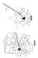
- FIGS. 1-13illustrate various steps of practicing a preferred method of a minimally invasive spine augmentation and stabilization system of the present invention, with portions of a vertebra being generally transparent for clarity;
- FIG. 14Aillustrates a front perspective view of a chassis of the minimally invasive spine augmentation and stabilization system
- FIG. 14Billustrates a top plan, partial cross-sectional view of the chassis of FIG. 14A .
- a containment device 125a containment device 125
- the containment device 125preferably creates a cavity within the interior volume of the vertebral body V, restores the height of the vertebral body V, fills the cavity formed in the vertebral body V and stabilizes, aids and/or augments the patient's vertebral body V and spine.
- the preferred containment device 125will be described as and may generally be used in the spine (for example, in the lumbar, thoracic or cervical regions), those skilled in the art will appreciate that the containment device 125 may be used in other parts of the body such as, for example, long bones or bones in the hand, face, feet, extremities, cranium, or in nearly any bone in the human body.
- FIGS. 10A-13As disclosed in International Patent Application No. PCT/US2008/083350 (published application No. WO 2009/064847), filed Nov. 13, 2008, titled “Porous Containment Device and Associated Method for Stabilization of Vertebral Compression Fractures, which claims priority to U.S. Provisional Patent Application No. 60/988,696, filed Nov.
- the system, method and instrumentation of the present inventionis preferably used in conjunction with a porous or permeable containment device 125 for implantation into the interior volume of a targeted vertebral body V for use in restoring the anatomy of the targeted vertebral body V.
- the containment device 125is expandable from an insertion configuration to an expanded configuration via, for example, a bone filler material such as, for example, a bone cement.
- Expansion of the containment device 125 by injection of the bone filler materialpreferably facilitates (i) cavity creation within the interior volume of the targeted vertebral body V, (ii) height restoration of the targeted vertebral body V, (iii) filling of the cavity formed in the interior volume of the targeted vertebral body V, and (iv) stabilization, aiding and/or augmentation of the targeted vertebral body V.
- the porous or permeable containment device 125preferably enables (i) controlled bone cement outflow, (ii) increased contact surface with the surrounding cancellous bone and (iii) stabilization of the rotational and axial-translational movements of the porous containment device 125 with respect to the surrounding cancellous bone.
- the containment device 125may be formed from a compliant, semi-compliant or non-compliant material.
- the containment device 125is preferably constructed from a PEEK material and is designed to have a pre-determined, specific shape when in the expanded configuration. More preferably, the containment device 125 has a dogbone-like or barbell-like shape in the expanded configuration to enhance stabilization with the surrounding cancellous bone. That is, the containment device 125 , upon expansion or inflation, includes a leading end portion 125 a , a trailing end portion 125 b and a middle portion 125 c therebetween such that the containment device 125 has first and second bulbous end portions and a comparatively narrow middle portion.
- the containment device 125preferably permits the bone filler material to flow out of or through the outer surface of the containment device 125 .
- the containment device 125includes a plurality of holes or pores (not shown) formed in the outer surface for secreting the bone filler material.
- the plurality of holes or poresare position in the anterior-facing surface of the middle portion 125 c of the containment device 125 to direct the excretion of the bone filler material anteriorly out of the containment device 125 as the containment device 125 expands via injection of the bone filler material.
- the geometry of the containment device 125 in the expanded configurationserves as a barrier to confine the excreted bolus of bone filler material 130 anterior to the expanded containment device 125 and to limit bone filler material from flowing posteriorly or laterally with respect to the middle portion 125 c of the containment device 125 .
- the pores or holesmay also incorporate a specifically designed shape and configuration to optimally meet the requirements of secreting the bone filler material, tissue infiltration and anchorage of the containment device 125 to the surrounding bone tissue.
- the containment device 125may include one or more flow-directing tentacles (not shown) extending from the outer surface or be formed at least partially from a permeable material, etc. to enable the bone filler material to be secreted from the containment device 125 to interdigitate with the surrounding bone tissue.
- the containment device 125may also include one or more knobs or ribs (not shown) to facilitate anchoring of the containment device 125 to the surrounding bone tissue, one or more air or fluid evacuation pores (not shown) to permit air or fluid from escaping from the interior volume of the containment device 125 , and/or one or more radiopacity rings or markers (not shown) to enable a surgeon to locate and/or position the containment device 125 under X-ray imaging.
- the targeted vertebral body Vincludes an anterior side, a posterior side, lateral sides therebetween, a superior portion, an inferior portion with a height therebetween, a spinous process, first and second transverse processes, and an intervertebral disc that is adhered both superiorly and inferiorly with respect to the damaged vertebral body V and which separates the damaged vertebral body V from adjacent vertebral bodies or vertebrae.
- the damaged vertebral body Vis shown in a generally transparent configuration in FIGS. 1-13 to generally improve clarity of the components and steps of the preferred minimally invasive spine augmentation and stabilization system and method.
- the system and methodpreferably includes a rigid first guidewire 102 , a working cannula 103 and a second guidewire 104 .
- the first guidewire 102may be a stylet, a K-wire, a guide pin, etc.
- the working cannula 103preferably includes a proximal end (not shown), a distal end 103 a and a hollow interior passageway (not shown) extending from the proximal end to the distal end 103 a for enabling other instruments or elements to be advanced into the targeted vertebral body V.
- the second guidewire 104which may also be in the form of a stylet, K-wire or guide pin, is designed and constructed so that at least a distal portion 104 a thereof is at least partially flexible.
- the second guidewire 104includes a curved distal portion 104 a .
- the curved distal portion 104 a of the second guidewire 104may be constructed by manufacturing the second guidewire 104 from a shape memory material so that the curved distal portion 104 a of the second guide wire 104 can assume a straight configuration so that it can be inserted through the hollow interior passageway of the working cannula 103 . Thereafter, at least the distal portion 104 a of the second guidewire 104 reassumes, bends or curves upon exiting the distal end 103 a of the working cannula 103 .
- the second guidewire 104is not limited to being manufactured from a shape memory material and that the second guidewire 104 may be manufactured from any material as long as the distal portion 104 a thereof is designed and constructed to have a curved or bent distal end such that the distal end 104 a generally extends laterally across an anterior portion of the vertebral body V when the second guidewire 104 extends out of the cannula 103 in an insertion position.
- the system and methodpreferably also includes a hollow plunger or other cavity creation device 105 that is advanceable over the second guidewire 104 and into the vertebral body V.
- the plunger or other cavity creation device 105is guided along the path created by the second guidewire 104 .
- the plunger or other cavity creation device 105assists in further creating or enlarging the introduction pathway for subsequently introduced elements of the system by creating a cavity along the exterior of the second guidewire 104 and thus enlarging the pathway created by the second guidewire 104 .
- the exterior of the plunger 105may include corrugation or other exterior surface features to assist in developing the pathway.
- the hollow plunger or cavity creation device 105is preferably at least partially flexible and includes a bendable or curveable distal portion 105 a so that upon exiting the distal end 103 a of the working cannula 103 , the distal portion 105 a of the plunger or cavity creation device 105 bends or curves to follow the path of the second guidewire 104 .
- the plunger or cavity creation device 105may be manufactured from a shape memory material so that the distal portion 105 a of the plunger or cavity creation device 105 initially assumes a straight configuration so that it can be inserted through the hollow interior passageway of the working cannula 103 . Thereafter, at least the distal portion 105 a of the plunger or cavity creation device 105 reassumes a distally bent or curved shape upon exiting the distal end 103 a of the working cannula 103 .
- the plunger or cavity creation device 105is not limited to being manufactured from a shape memory material and that the plunger or cavity creation device 105 may be manufactured from any material as long as the distal portion 105 a thereof is designed and constructed to have a curved or bent distal end such that the distal end 105 a is capable of bending or curving to follow the path of the second guidewire 104 .
- the plunger or cavity creation device 105may be generally flexible to follow the path of the second guidewire 104 to direct the distal end 105 a of the plunger or cavity creation device 105 along the path defined by the second guidewire 104 within the vertebral body V.
- the system and methodpreferably also includes a cannulated sleeve 108 , a containment device chassis 110 and the containment device 125 .
- the cannulated sleeve 108includes a proximal portion (not shown), a distal portion (not shown) and a interior passageway extending from the proximal portion to the distal portion.
- the cannulated sleeve 108is sized and configured to be inserted into the interior passageway of the working cannula 103 .
- the distal portion of the cannulated sleeve 108is preferably detachably coupled to the containment device chassis 110 .
- the proximal portionis preferably coupleable with a mechanism such as, for example, a syringe (not shown) for introducing bone filler material or bone cement through the cannulated sleeve 108 and into the interior of the containment device 125 , which is preferably housed inside of the chassis 110 .
- a mechanismsuch as, for example, a syringe (not shown) for introducing bone filler material or bone cement through the cannulated sleeve 108 and into the interior of the containment device 125 , which is preferably housed inside of the chassis 110 .
- the chassis 110includes a leading end 110 a and a trailing end 110 b wherein the leading end 110 a may include a bullet nose tip or other taper for ease of advancement within the interior of the vertebral body V.
- the trailing end 110 bis detachably coupled to the cannulated sleeve 108 .
- the chassis 110preferably also includes a hollow cavity 110 c sized and configured to house or contain the containment device 125 when the containment device 125 is in the insertion configuration.
- An anterior portion of the chassis 110preferably includes a window 111 to direct outward expansion of the containment device 125 upon inflation with the bone filler material or bone cement.
- the chassis 110preferably has a curvature similar to the curvature of the distal end 104 a of the second guidewire 104 and the distal end 105 a of the plunger or cavity creation device 105 .
- the chassis 110may be manufactured from a shape memory material so that the chassis 110 assumes the shape of the hollow interior passageway of the working cannula 103 , as the chassis 110 is being inserted through the working cannula 103 .
- the chassis 110Upon exiting the distal end 103 a of the working cannula 103 , the chassis 110 preferably reassume its curved shape.
- the chassis 110is not limited to being manufactured from a shape memory material and that the chassis 110 may be manufactured from any material as long as the chassis 110 is curveable or bendable to follow the path of the second guidewire 104 .
- the chassis 110is preferably formed from a material such as polyetheretherketone (PEEK), Nitinol, titanium, etc., but is not so limited.
- PEEKpolyetheretherketone
- the posterior exterior or interior surface of the chassis 110preferably includes a groove or slot 114 that is configured to mate with the second guide wire 104 such that the chassis 110 can be directed along the second guide wire 104 and into a desired position within the interior of the damaged vertebral body V.
- the detachable coupling between the proximal end 110 b of the chassis 110 and the distal end of the cannulated sleeve 108may be by any mechanism now or hereafter known including, but not limited to, a friction fit, a press fit, or a force fit.
- the cannulated sleeve 108may be coupled to the chassis 110 by pressure and all forces can be transmitted by friction.
- the chassis 110can be decoupled from the cannulated sleeve 108 by holding the chassis 110 in place and pulling the cannulated sleeve 108 away from the chassis 110 .
- the cannulated sleeve 108may be coupled to the chassis 110 by a threaded connection, a bayonet coupling, or a plug-in connector such as by a pin formed in the cannulated sleeve 108 for engaging a slot formed in the chassis 110 .
- the cannulated sleeve 108may be coupled to the chassis 110 via deformation of an elastic element (not shown). That is, the cannulated sleeve 108 may include an inner cannulated sleeve (not shown) and an outer cannulated sleeve (not shown) wherein the outer cannulated sleeve is movably associated with the inner cannulated sleeve.
- the elastic elementmay surround the inner cannulated sleeve, preferably adjacent the distal end thereof. The inner cannulated sleeve and elastic element are inserted into the chassis 110 .
- the outer cannulated sleeveis moved relative to the inner cannulated sleeve so that the distal end of the outer cannulated sleeve contacts the elastic element.
- the elastic elementis moved relative to the inner cannulated sleeve so that the distal end of the outer cannulated sleeve contacts the elastic element.
- the outer cannulated sleevemay be coupled to the elastic compression ring so that movement of the inner cannulated sleeve with respect to the outer cannulated sleeve causes the inner cannulated sleeve to contact and subsequently compress the elastic compression ring, which in turn causes the compression ring to expand and press against the chassis 110 .
- the cannulated sleeve 108may be coupled to the chassis 110 by an intermediate clamping element (not shown).
- the cannulated sleeve 108may include an inner cannulated sleeve (not shown) and an outer cannulated sleeve (not shown) wherein the outer cannulated sleeve is movably associated with the inner cannulated sleeve.
- the intermediate clamping elementmay be formed on or coupled to the inner cannulated sleeve, preferably on the outer surface of the inner cannulated sleeve adjacent to a distal end thereof.
- the chassis 110is thereafter placed between the inner cannulated sleeve and the intermediate clamping element.
- the cannulated sleeve 108may be integrally formed with the chassis 110 .
- the integrally formed cannulated sleeve 108 and implant chassis 110may be separated by a predefined breaking region such that during the procedure the chassis 110 is separated from the cannulated sleeve 108 by rupturing the breaking region.
- the first guide wire 102is introduced through the skin and musculature and into the interior volume of the targeted damaged vertebral body V, as illustrated in FIG. 1 .
- the first guide wire 102is introduced through a single transverse process or through one of the pedicles.
- the working cannula 103is introduced over the first guidewire 102 until the distal end 103 a of the working cannula 103 is placed adjacent to an exterior of the targeted vertebral body V, as illustrated in FIG. 2 .
- the distal end 103 a of the working cannula 103may be placed with the interior volume of the vertebral body V.
- the first guidewire 102is then removed leaving the working cannula 103 in place, as illustrated in FIG. 3 .
- the second guidewire 104is then introduced through the working cannula 103 and into the interior of the vertebral body V, as illustrated in FIGS. 4A and 4B .
- the second guidewire 104Upon exiting the distal end 103 a of the working cannula 103 , the second guidewire 104 curves or bends toward an opposite side of the vertebral body V as the second guidewire 104 is being introduced into the interior volume of the vertebral body V.
- the second guidewire 104follows a path interior to the vertebral body V that has a concave side facing the posterior of the vertebral body V and a convex side facing the anterior of the vertebral body V.
- the distal end 104 a of the second guidewire 104is preferably position proximate the posterior wall of the vertebral body V. The insertion and positioning of the second guidewire 104 creates an introduction pathway for subsequently introduced elements of the system.
- the plunger or cavity creation device 105is introduced over the second guidewire 104 .
- the plunger or cavity creation device 105is directed along the path created by the second guidewire 104 , as illustrated in FIGS. 5A and 5B .
- the plunger or cavity creation device 105assists in further enlarging the introduction pathway for subsequently introduced elements of the system by creating a cavity along the exterior of the second guidewire 104 and thus enlarging the pathway created by the second guidewire 104 .
- the exterior of the plunger 105may include corrugation or other exterior surface features to assist in developing the pathway.
- the plunger 105is then removed from the interior volume of the vertebral body V while retaining the second guidewire 104 and the working cannula 103 in place, as illustrated in FIGS. 6A and 6B .
- the cannulated sleeve 108which includes the chassis 110 detachably coupled to the distal end thereof, is advanced through the working cannula 103 and into the interior volume of the vertebral body V along the introductory pathway created by the second guidewire 104 and the plunger or cavity creation device 105 .
- the chassis 110is inserted and travels over the second guidewire 104 .
- the slot 114 formed on the interior or exterior posterior surface of the chassis 110preferably interacts with the second guidewire 104 to steer the chassis 110 into position within the vertebral body V, as illustrated in FIGS. 7A-8B .
- the folded containment device 125is protected from damage during insertion due to its partial enclosure by the chassis 110 .
- the containment device 125may be introduced in a second step that occurs after positioning the chassis 110 —filling and expansion of the containment device 125 is preformed as described below.
- the containment device 125is then expanded via introduction of the bone filler matter (e.g., bone cement).
- the introduction of bone cementis preferably performed via a two step process. That is, a low viscosity bone cement is injected through the cannulated sleeve 108 and into the containment device 125 causing the containment device 125 to unfold and partially expand anteriorly out of the anterior window 111 formed in the chassis 110 .
- a small amount of bone cementis secreted through the pores toward the anterior portion of the vertebral body V. Secretion of the bone cement through the pores preferably forms the cement bolus 130 .
- a higher viscosity bone cementis then preferably injected through the cannulated sleeve 108 and into the containment device 125 to further expand the containment device 125 .
- additional bone cementis secreted through the pores formed in the containment device 125 .
- injection of the higher viscosity bone cementpreferably restores the height of the vertebral body V.
- the outflow of bone cement through the pores, resulting in the cement bolus 130is preferably directed anteriorly to limit posterior or lateral cement flow within the vertebral body V. The posterior and lateral cement flow is limited by the barrier formed by the geometry of the expanded containment device 125 and the chassis 110 .
- the secreted bone cement 130preferably provides interdigitation and stabilization to limit slippage between the containment device 125 and the surrounding bone tissue interior to the vertebral body V.
- the bone cement injected into the containment device 125provides height restoration and conservation of the spacing between the endplates of the vertebral body V.
- the barrier to posterior cement flow within the vertebral body Vthat is provided by the geometry of the expanded containment device 125 and the chassis 110 limits the bone cement from leaking through any fracture lines inherent on the posterior wall of the vertebral body V, a condition noted in about forty percent (40%) of all vertebral body fracture cases.
- the system and methoduses a two-step process for injecting the bone cement
- the system and methodis not so limited and the containment device 125 may be inflated using a single-step process or a process involving more than two steps.
- the introduction of the containment device 125 through a single transverse process or pedicle and the elongated curved or bent geometry of the second guidewire 104permits a less invasive procedure than a bi-pedicular or bi-transverse process approach in which a pair of devices or implants are introduced into the interior of the vertebral body V.
- the chassis 110is uncoupled from the distal end of the cannulated sleeve 108 by actuating or employing any of the above described appropriate detachment mechanisms, depending on the particular mechanism chosen for the system, at which point the cannulated sleeve 108 is removed from the working cannula 103 .
- the working cannula 103 and the second guidewire 104are preferably removed from the patient's body, as illustrated in FIGS. 12A-13 , while leaving the containment device 125 and chassis 110 , as well as the cement bolus 130 , within the interior of the vertebral body V.
- the containment device 125may be partially or fully removed from the vertebral body V by creating weakened portions in the containment device 125 along which the containment device 125 may tear to permit at least partial removal of the containment device 125 from the vertebral body V.
Landscapes
- Health & Medical Sciences (AREA)
- Orthopedic Medicine & Surgery (AREA)
- Life Sciences & Earth Sciences (AREA)
- Surgery (AREA)
- Neurology (AREA)
- General Health & Medical Sciences (AREA)
- Veterinary Medicine (AREA)
- Public Health (AREA)
- Animal Behavior & Ethology (AREA)
- Engineering & Computer Science (AREA)
- Biomedical Technology (AREA)
- Heart & Thoracic Surgery (AREA)
- Molecular Biology (AREA)
- Medical Informatics (AREA)
- Nuclear Medicine, Radiotherapy & Molecular Imaging (AREA)
- Biophysics (AREA)
- Pulmonology (AREA)
- Anesthesiology (AREA)
- Hematology (AREA)
- Epidemiology (AREA)
- Surgical Instruments (AREA)
- Prostheses (AREA)
Abstract
Description
Claims (27)
Priority Applications (1)
| Application Number | Priority Date | Filing Date | Title |
|---|---|---|---|
| US12/755,256US8911497B2 (en) | 2009-04-09 | 2010-04-06 | Minimally invasive spine augmentation and stabilization system and method |
Applications Claiming Priority (2)
| Application Number | Priority Date | Filing Date | Title |
|---|---|---|---|
| US16804609P | 2009-04-09 | 2009-04-09 | |
| US12/755,256US8911497B2 (en) | 2009-04-09 | 2010-04-06 | Minimally invasive spine augmentation and stabilization system and method |
Publications (2)
| Publication Number | Publication Date |
|---|---|
| US20100262242A1 US20100262242A1 (en) | 2010-10-14 |
| US8911497B2true US8911497B2 (en) | 2014-12-16 |
Family
ID=42225115
Family Applications (1)
| Application Number | Title | Priority Date | Filing Date |
|---|---|---|---|
| US12/755,256Active2032-02-06US8911497B2 (en) | 2009-04-09 | 2010-04-06 | Minimally invasive spine augmentation and stabilization system and method |
Country Status (9)
| Country | Link |
|---|---|
| US (1) | US8911497B2 (en) |
| EP (1) | EP2416721B1 (en) |
| JP (1) | JP5662999B2 (en) |
| KR (1) | KR20120028873A (en) |
| CN (1) | CN102448393A (en) |
| BR (1) | BRPI1014890A2 (en) |
| CA (1) | CA2757829A1 (en) |
| ES (1) | ES2430913T3 (en) |
| WO (1) | WO2010118021A1 (en) |
Cited By (13)
| Publication number | Priority date | Publication date | Assignee | Title |
|---|---|---|---|---|
| US10617530B2 (en) | 2011-07-14 | 2020-04-14 | Seaspine, Inc. | Laterally deflectable implant |
| US10905440B2 (en) | 2008-09-26 | 2021-02-02 | Relievant Medsystems, Inc. | Nerve modulation systems |
| US11007010B2 (en) | 2019-09-12 | 2021-05-18 | Relevant Medsysterns, Inc. | Curved bone access systems |
| US11065046B2 (en) | 2013-08-08 | 2021-07-20 | Relievant Medsystems, Inc. | Modulating nerves within bone |
| US11160563B2 (en) | 2012-11-05 | 2021-11-02 | Relievant Medsystems, Inc. | Systems for navigation and treatment within a vertebral body |
| US20220304824A1 (en)* | 2019-03-07 | 2022-09-29 | Spinal Surgical Strategies, Inc., A Nevada Corporation D/B/A Kleiner Device Labs | Bone graft delivery system and method for using same |
| US11471210B2 (en) | 2011-12-30 | 2022-10-18 | Relievant Medsystems, Inc. | Methods of denervating vertebral body using external energy source |
| US11596468B2 (en) | 2002-09-30 | 2023-03-07 | Relievant Medsystems, Inc. | Intraosseous nerve treatment |
| US11690667B2 (en) | 2012-09-12 | 2023-07-04 | Relievant Medsystems, Inc. | Radiofrequency ablation of tissue within a vertebral body |
| US12039731B2 (en) | 2020-12-22 | 2024-07-16 | Relievant Medsystems, Inc. | Prediction of candidates for spinal neuromodulation |
| US12082876B1 (en) | 2020-09-28 | 2024-09-10 | Relievant Medsystems, Inc. | Introducer drill |
| US12303166B2 (en) | 2008-09-26 | 2025-05-20 | Relievant Medsystems, Inc. | Methods for accessing nerves within bone |
| US12433668B1 (en) | 2021-11-08 | 2025-10-07 | Relievant Medsystems, Inc. | Impedance stoppage mitigation during radiofrequency tissue ablation procedures |
Families Citing this family (41)
| Publication number | Priority date | Publication date | Assignee | Title |
|---|---|---|---|---|
| US20180228621A1 (en) | 2004-08-09 | 2018-08-16 | Mark A. Reiley | Apparatus, systems, and methods for the fixation or fusion of bone |
| US7988735B2 (en)* | 2005-06-15 | 2011-08-02 | Matthew Yurek | Mechanical apparatus and method for delivering materials into the inter-vertebral body space for nucleus replacement |
| US8114156B2 (en)* | 2008-05-30 | 2012-02-14 | Edwin Burton Hatch | Flexibly compliant ceramic prosthetic meniscus for the replacement of damaged cartilage in orthopedic surgical repair or reconstruction of hip, knee, ankle, shoulder, elbow, wrist and other anatomical joints |
| US8998925B2 (en)* | 2011-06-20 | 2015-04-07 | Rdc Holdings, Llc | Fixation system for orthopedic devices |
| US8814873B2 (en) | 2011-06-24 | 2014-08-26 | Benvenue Medical, Inc. | Devices and methods for treating bone tissue |
| US9724132B2 (en) | 2011-08-31 | 2017-08-08 | DePuy Synthes Products, Inc. | Devices and methods for cervical lateral fixation |
| US9044321B2 (en) | 2012-03-09 | 2015-06-02 | Si-Bone Inc. | Integrated implant |
| US10363140B2 (en) | 2012-03-09 | 2019-07-30 | Si-Bone Inc. | Systems, device, and methods for joint fusion |
| EP3818947B1 (en) | 2012-05-04 | 2023-08-30 | SI-Bone, Inc. | Fenestrated implant |
| CN103027731A (en)* | 2012-12-29 | 2013-04-10 | 陈秋良 | Vertebral body support for vertebral body bone cement implanting operation |
| US10085783B2 (en) | 2013-03-14 | 2018-10-02 | Izi Medical Products, Llc | Devices and methods for treating bone tissue |
| US9572676B2 (en)* | 2013-03-14 | 2017-02-21 | DePuy Synthes Products, Inc. | Adjustable multi-volume balloon for spinal interventions |
| US9480574B2 (en) | 2013-03-14 | 2016-11-01 | Benvenue Medical, Inc. | Spinal fusion implants and devices and methods for deploying such implants |
| US9585761B2 (en) | 2013-03-14 | 2017-03-07 | DePuy Synthes Products, Inc. | Angulated rings and bonded foils for use with balloons for fusion and dynamic stabilization |
| US9358120B2 (en) | 2013-03-14 | 2016-06-07 | DePuy Synthes Products, Inc. | Expandable coil spinal implant |
| WO2014145902A1 (en) | 2013-03-15 | 2014-09-18 | Si-Bone Inc. | Implants for spinal fixation or fusion |
| US11147688B2 (en) | 2013-10-15 | 2021-10-19 | Si-Bone Inc. | Implant placement |
| CN103690228B (en)* | 2013-12-12 | 2015-11-25 | 宁波华科润生物科技有限公司 | Centrum expansion ball bag system |
| US10314605B2 (en)* | 2014-07-08 | 2019-06-11 | Benvenue Medical, Inc. | Apparatus and methods for disrupting intervertebral disc tissue |
| US10166033B2 (en)* | 2014-09-18 | 2019-01-01 | Si-Bone Inc. | Implants for bone fixation or fusion |
| JP6542362B2 (en) | 2014-09-18 | 2019-07-10 | エスアイ−ボーン・インコーポレイテッドSi−Bone, Inc. | Matrix implant |
| KR101647457B1 (en)* | 2014-11-25 | 2016-08-10 | 주식회사 메드릭스 | Band coupling device for spinous process |
| CN104546089A (en)* | 2015-01-09 | 2015-04-29 | 彭大勇 | Percutaneous puncture transverse balloon distraction percutaneous kyphoplasty surgical instrument |
| US10022243B2 (en) | 2015-02-06 | 2018-07-17 | Benvenue Medical, Inc. | Graft material injector system and method |
| CN105167836B (en)* | 2015-08-07 | 2017-12-08 | 昆明医科大学第一附属医院 | A kind of guided by saccule device for the operation of pedicle of vertebral arch approach kyphoplasty |
| CN106420033B (en)* | 2016-09-28 | 2023-06-20 | 上海凯利泰医疗科技股份有限公司 | Bone filler push injection system |
| CN106388924A (en)* | 2016-09-28 | 2017-02-15 | 上海凯利泰医疗科技股份有限公司 | Bone filler injecting system |
| ES2672265B1 (en)* | 2016-11-07 | 2019-04-10 | Inst Biomecanico De Barcelona S L | DEVICE FOR INTERVERTEBRAL FUSION COMPRISING AN INTERVERTEBRAL STABILIZATION SCREW AND A COMPOSITION FOR BONE REMODELING |
| US10758286B2 (en) | 2017-03-22 | 2020-09-01 | Benvenue Medical, Inc. | Minimal impact access system to disc space |
| US11116519B2 (en) | 2017-09-26 | 2021-09-14 | Si-Bone Inc. | Systems and methods for decorticating the sacroiliac joint |
| WO2019148083A1 (en) | 2018-01-29 | 2019-08-01 | Benvenue Medical, Inc. | Minimally invasive interbody fusion |
| WO2019178575A1 (en) | 2018-03-16 | 2019-09-19 | Benvenue Medical, Inc. | Articulated instrumentation and methods of using the same |
| ES3011907T3 (en) | 2018-03-28 | 2025-04-08 | Si Bone Inc | Threaded implants for use across bone segments |
| US11369419B2 (en) | 2019-02-14 | 2022-06-28 | Si-Bone Inc. | Implants for spinal fixation and or fusion |
| EP4613244A2 (en) | 2019-02-14 | 2025-09-10 | SI-Bone Inc. | Implants for spinal fixation and or fusion |
| JP7646654B2 (en) | 2019-11-21 | 2025-03-17 | エスアイ-ボーン・インコーポレイテッド | Rod coupling assembly for bone stabilization construct - Patent application |
| AU2020392121B2 (en) | 2019-11-27 | 2025-05-22 | Si-Bone, Inc. | Bone stabilizing implants and methods of placement across SI joints |
| EP4072452A4 (en) | 2019-12-09 | 2023-12-20 | SI-Bone, Inc. | Sacro-iliac joint stabilizing implants and methods of implantation |
| EP4259015A4 (en) | 2020-12-09 | 2024-09-11 | SI-Bone, Inc. | SACROILIAC JOINT STABILIZATION IMPLANTS AND METHODS OF IMPLANTATION |
| CN115500926B (en)* | 2022-09-21 | 2024-09-13 | 宁波华科润生物科技有限公司 | Directional expansion sacculus system |
| WO2025038769A1 (en) | 2023-08-15 | 2025-02-20 | Si-Bone Inc. | Pelvic stabilization implants, methods of use and manufacture |
Citations (122)
| Publication number | Priority date | Publication date | Assignee | Title |
|---|---|---|---|---|
| US2381050A (en) | 1943-12-04 | 1945-08-07 | Mervyn G Hardinge | Fracture reducing device |
| US3701703A (en) | 1969-12-04 | 1972-10-31 | Norton Co | Method of making an abrasive foam laminate |
| US3867728A (en) | 1971-12-30 | 1975-02-25 | Cutter Lab | Prosthesis for spinal repair |
| US4055029A (en) | 1975-03-07 | 1977-10-25 | Heinz Kalbow | Cleaning, scouring and/or polishing pads |
| US4327736A (en) | 1979-11-20 | 1982-05-04 | Kanji Inoue | Balloon catheter |
| US4364392A (en) | 1980-12-04 | 1982-12-21 | Wisconsin Alumni Research Foundation | Detachable balloon catheter |
| US4735625A (en) | 1985-09-11 | 1988-04-05 | Richards Medical Company | Bone cement reinforcement and method |
| US4755184A (en) | 1986-01-09 | 1988-07-05 | Mark Silverberg | Bone augmentation implant |
| US4820349A (en) | 1987-08-21 | 1989-04-11 | C. R. Bard, Inc. | Dilatation catheter with collapsible outer diameter |
| US4969888A (en) | 1989-02-09 | 1990-11-13 | Arie Scholten | Surgical protocol for fixation of osteoporotic bone using inflatable device |
| US4986830A (en) | 1989-09-22 | 1991-01-22 | Schneider (U.S.A.) Inc. | Valvuloplasty catheter with balloon which remains stable during inflation |
| US5041114A (en) | 1986-06-23 | 1991-08-20 | Pfizer Hospital Products Group, Inc. | Modular femoral fixation system |
| US5049132A (en) | 1990-01-08 | 1991-09-17 | Cordis Corporation | Balloon catheter for delivering therapeutic agents |
| US5059193A (en) | 1989-11-20 | 1991-10-22 | Spine-Tech, Inc. | Expandable spinal implant and surgical method |
| US5098381A (en) | 1988-04-20 | 1992-03-24 | Schneider Europe | Catheter for recanalizing constricted vessels |
| US5192326A (en) | 1990-12-21 | 1993-03-09 | Pfizer Hospital Products Group, Inc. | Hydrogel bead intervertebral disc nucleus |
| US5352199A (en) | 1993-05-28 | 1994-10-04 | Numed, Inc. | Balloon catheter |
| US5390683A (en) | 1991-02-22 | 1995-02-21 | Pisharodi; Madhavan | Spinal implantation methods utilizing a middle expandable implant |
| WO1995005209A1 (en) | 1993-08-18 | 1995-02-23 | Technology Development Center | Treatment chamber catheter |
| US5443496A (en) | 1992-03-19 | 1995-08-22 | Medtronic, Inc. | Intravascular radially expandable stent |
| WO1996004952A1 (en) | 1994-08-08 | 1996-02-22 | Schneider (Usa) Inc. | Drug delivery and dilatation-drug delivery catheters in a rapid exchange configuration |
| US5549679A (en) | 1994-05-20 | 1996-08-27 | Kuslich; Stephen D. | Expandable fabric implant for stabilizing the spinal motion segment |
| US5599301A (en) | 1993-11-22 | 1997-02-04 | Advanced Cardiovascular Systems, Inc. | Motor control system for an automatic catheter inflation system |
| US5601593A (en) | 1995-03-06 | 1997-02-11 | Willy Rusch Ag | Stent for placement in a body tube |
| EP0493789B1 (en) | 1990-12-29 | 1997-03-26 | MUDR. MILAN KRAJICEK CSc. | Device for the osteosynthesis of bones |
| US5674295A (en) | 1994-10-17 | 1997-10-07 | Raymedica, Inc. | Prosthetic spinal disc nucleus |
| US5693100A (en) | 1991-02-22 | 1997-12-02 | Pisharodi; Madhavan | Middle expandable intervertebral disk implant |
| US5707390A (en) | 1990-03-02 | 1998-01-13 | General Surgical Innovations, Inc. | Arthroscopic retractors |
| US5759191A (en) | 1989-06-27 | 1998-06-02 | C. R. Bard, Inc. | Coaxial PTCA catheter with anchor joint |
| US5800392A (en) | 1995-01-23 | 1998-09-01 | Emed Corporation | Microporous catheter |
| EP0872257A2 (en) | 1997-04-15 | 1998-10-21 | Schneider (Europe) GmbH | Catheter |
| US5827289A (en) | 1994-01-26 | 1998-10-27 | Reiley; Mark A. | Inflatable device for use in surgical protocols relating to treatment of fractured or diseased bones |
| WO1998056301A1 (en) | 1997-06-09 | 1998-12-17 | Kyphon Inc. | Systems for treating fractured or diseased bone using expandable bodies |
| US5893850A (en) | 1996-11-12 | 1999-04-13 | Cachia; Victor V. | Bone fixation device |
| US5972015A (en) | 1997-08-15 | 1999-10-26 | Kyphon Inc. | Expandable, asymetric structures for deployment in interior body regions |
| WO2000033909A1 (en) | 1998-12-09 | 2000-06-15 | Cook Incorporated | Hollow, curved, superelastic medical needle |
| US6096038A (en) | 1988-06-13 | 2000-08-01 | Michelson; Gary Karlin | Apparatus for inserting spinal implants |
| US6127597A (en) | 1997-03-07 | 2000-10-03 | Discotech N.V. | Systems for percutaneous bone and spinal stabilization, fixation and repair |
| US6179856B1 (en) | 1989-07-05 | 2001-01-30 | Medtronic Ave, Inc. | Coaxial PTCA catheter with anchor joint |
| US6235043B1 (en) | 1994-01-26 | 2001-05-22 | Kyphon, Inc. | Inflatable device for use in surgical protocol relating to fixation of bone |
| US6241734B1 (en) | 1998-08-14 | 2001-06-05 | Kyphon, Inc. | Systems and methods for placing materials into bone |
| US6248110B1 (en) | 1994-01-26 | 2001-06-19 | Kyphon, Inc. | Systems and methods for treating fractured or diseased bone using expandable bodies |
| US6306177B1 (en) | 1994-05-06 | 2001-10-23 | Advanced Bio Surfaces, Inc. | Biomaterial system for in situ tissue repair |
| WO2001076514A3 (en) | 2000-04-05 | 2002-05-02 | Kyphon Inc | Methods and devices for treating fractured and/or diseased bone |
| US20020058947A1 (en) | 2000-02-28 | 2002-05-16 | Stephen Hochschuler | Method and apparatus for treating a vertebral body |
| US6395032B1 (en) | 1998-12-11 | 2002-05-28 | Dimso (Distribution Medicale Du Sud-Ouest) | Intervertebral disc prosthesis with liquid chamber |
| WO2002043628A1 (en) | 2000-12-01 | 2002-06-06 | Sabitzer Ronald J | Method and device for expanding a body cavity |
| US20020068974A1 (en) | 2000-07-21 | 2002-06-06 | Kuslich Stephen D. | Expandable porous mesh bag device and methods of use for reduction, filling, fixation and supporting of bone |
| US6402784B1 (en) | 1997-07-10 | 2002-06-11 | Aberdeen Orthopaedic Developments Limited | Intervertebral disc nucleus prosthesis |
| US6440138B1 (en) | 1998-04-06 | 2002-08-27 | Kyphon Inc. | Structures and methods for creating cavities in interior body regions |
| US6478800B1 (en) | 2000-05-08 | 2002-11-12 | Depuy Acromed, Inc. | Medical installation tool |
| WO2003007853A1 (en) | 2000-07-21 | 2003-01-30 | The Spineology Group, Llc | An expandable porous mesh bag device and its use for bone surgery |
| US6558390B2 (en) | 2000-02-16 | 2003-05-06 | Axiamed, Inc. | Methods and apparatus for performing therapeutic procedures in the spine |
| US6565606B1 (en) | 1998-09-09 | 2003-05-20 | Lanka Limited | Implant, method of making the same and use the same |
| US6620162B2 (en) | 2001-07-20 | 2003-09-16 | Spineology, Inc. | Device for inserting fill material particles into body cavities |
| US6632235B2 (en) | 2001-04-19 | 2003-10-14 | Synthes (U.S.A.) | Inflatable device and method for reducing fractures in bone and in treating the spine |
| US6638246B1 (en) | 2000-11-28 | 2003-10-28 | Scimed Life Systems, Inc. | Medical device for delivery of a biologically active material to a lumen |
| US6679886B2 (en) | 2000-09-01 | 2004-01-20 | Synthes (Usa) | Tools and methods for creating cavities in bone |
| US6706069B2 (en) | 2001-09-13 | 2004-03-16 | J. Lee Berger | Spinal grooved director with built in balloon |
| US6716216B1 (en) | 1998-08-14 | 2004-04-06 | Kyphon Inc. | Systems and methods for treating vertebral bodies |
| US6719773B1 (en) | 1998-06-01 | 2004-04-13 | Kyphon Inc. | Expandable structures for deployment in interior body regions |
| US6719761B1 (en) | 1997-08-13 | 2004-04-13 | Kyphon Inc. | System and methods for injecting flowable materials into bones |
| US6733532B1 (en) | 1998-12-11 | 2004-05-11 | Stryker Spine | Intervertebral disc prosthesis with improved mechanical behavior |
| US20040098017A1 (en) | 2002-09-30 | 2004-05-20 | Advanced Polymers, Incorporated | Apparatus and methods for bone, tissue and duct dilatation |
| US20040097930A1 (en) | 2002-08-27 | 2004-05-20 | Justis Jeff R. | Systems and methods for intravertebral reduction |
| US20040102774A1 (en) | 2002-11-21 | 2004-05-27 | Trieu Hai H. | Systems and techniques for intravertebral spinal stabilization with expandable devices |
| WO2004043271A1 (en) | 2002-11-08 | 2004-05-27 | Sdgi Holdings, Inc. | Transpedicular intervertebral disk access methods and devices |
| US20040167625A1 (en) | 1999-01-27 | 2004-08-26 | Disc-O-Tech Orthopedic Technologies Inc. | Spacer filler |
| JP2004248791A (en) | 2003-02-19 | 2004-09-09 | Mitsubishi Materials Corp | Instrument for bone treatment |
| US20040210297A1 (en) | 2003-04-18 | 2004-10-21 | A-Spine Holding Group Corp. | Filling device and system for treating a deformed or diseased spine |
| US20040220615A1 (en) | 2003-04-30 | 2004-11-04 | A-Spine Holding Group Corp. | Device and system for anchoring tissue to bone |
| US20050010297A1 (en) | 2003-05-08 | 2005-01-13 | Kuros Biosurgery Ag | Balloon technologies for tissue repair |
| US6852095B1 (en) | 1997-07-09 | 2005-02-08 | Charles D. Ray | Interbody device and method for treatment of osteoporotic vertebral collapse |
| US20050070911A1 (en) | 2003-09-29 | 2005-03-31 | Scimed Life Systems, Inc. | Apparatus and methods for reducing compression bone fractures using high strength ribbed members |
| WO2005048856A1 (en) | 2003-11-10 | 2005-06-02 | Umc Utrecht Holding B.V. | Expandable implant for treating fractured and/or collapsed bone |
| US20050209595A1 (en) | 2000-05-09 | 2005-09-22 | Regeneex Ltd. | Expandable devices and methods for tissue expansion, regeneration and fixation |
| US20050209629A1 (en) | 2001-04-19 | 2005-09-22 | Kerr Sean H | Resorbable containment device and process for making and using same |
| US20050234498A1 (en) | 2002-05-25 | 2005-10-20 | Dietrich Gronemeyer | Dilatable balloon implant |
| US6969404B2 (en) | 1999-10-08 | 2005-11-29 | Ferree Bret A | Annulus fibrosis augmentation methods and apparatus |
| US20050273049A1 (en) | 2004-06-08 | 2005-12-08 | Peter Krulevitch | Drug delivery device using microprojections |
| US20060009844A1 (en) | 2004-06-18 | 2006-01-12 | Aesculap Ag & Co. Kg | Implant |
| US7011684B2 (en) | 2002-01-17 | 2006-03-14 | Concept Matrix, Llc | Intervertebral disk prosthesis |
| US7025771B2 (en) | 2000-06-30 | 2006-04-11 | Spineology, Inc. | Tool to direct bone replacement material |
| US20060079905A1 (en) | 2003-06-17 | 2006-04-13 | Disc-O-Tech Medical Technologies Ltd. | Methods, materials and apparatus for treating bone and other tissue |
| WO2006034396A3 (en) | 2004-09-21 | 2006-05-11 | Stout Medical Group Lp | Balloon and methods of making and using |
| US20060100706A1 (en) | 2004-11-10 | 2006-05-11 | Shadduck John H | Stent systems and methods for spine treatment |
| US7044954B2 (en) | 1994-01-26 | 2006-05-16 | Kyphon Inc. | Method for treating a vertebral body |
| US20060106459A1 (en) | 2004-08-30 | 2006-05-18 | Csaba Truckai | Bone treatment systems and methods |
| US20060155296A1 (en) | 2005-01-07 | 2006-07-13 | Celonova Biosciences, Inc. | Three-dimensional implantable bone support |
| US20060173464A1 (en) | 2005-02-03 | 2006-08-03 | Ellman Alan G | Spinal fill for disk surgery |
| US20060182780A1 (en) | 2005-02-16 | 2006-08-17 | Riley Susan L | Resorbable hollow devices for implantation and delivery of therapeutic agents |
| US20060190083A1 (en) | 2003-07-25 | 2006-08-24 | Uri Arnin | Elastomeric spinal disc nucleus replacement |
| US20060217736A1 (en) | 2005-03-24 | 2006-09-28 | Gc Corporation | Bone cement injecting and filling method and leakage prevention bag for injecting and filling bone cement |
| US20060229625A1 (en) | 2004-11-10 | 2006-10-12 | Csaba Truckai | Bone treatment systems and methods |
| US20060271061A1 (en) | 2001-07-25 | 2006-11-30 | Disc-O-Tech, Ltd. | Deformable tools and implants |
| US20060293750A1 (en) | 2005-06-03 | 2006-12-28 | Sherman Michael C | Formed in place corpectomy device |
| US7166121B2 (en) | 1994-01-26 | 2007-01-23 | Kyphon Inc. | Systems and methods using expandable bodies to push apart cortical bone surfaces |
| US7175627B2 (en) | 2003-05-21 | 2007-02-13 | Crosstrees Medical, Inc. | Extractable filler for inserting medicine into animal tissue |
| US7175628B2 (en) | 2003-05-21 | 2007-02-13 | Crosstrees Medical, Inc. | Extractable filler for inserting medicine into animal tissue |
| US7175629B2 (en) | 2003-09-29 | 2007-02-13 | Crosstrees Medical, Inc. | Extractable filler for inserting medicine into vertebral body |
| US20070118142A1 (en) | 2005-11-18 | 2007-05-24 | Krueger John A | Device, system and method for delivering a curable material into bone |
| US7241303B2 (en) | 1994-01-26 | 2007-07-10 | Kyphon Inc. | Devices and methods using an expandable body with internal restraint for compressing cancellous bone |
| US20070168031A1 (en) | 2006-01-13 | 2007-07-19 | Zimmer Spine, Inc. | Devices and methods for disc replacement |
| US20070213760A1 (en) | 2004-10-15 | 2007-09-13 | Futuremed Interventional, Inc. | Non-compliant medical balloon having an integral woven fabric layer |
| US20070219490A1 (en) | 2004-10-15 | 2007-09-20 | Futuremed Interventional, Inc. | Non-compliant medical balloon having an integral non-woven fabric layer |
| US20070233258A1 (en) | 2006-02-28 | 2007-10-04 | Zimmer Spine, Inc. | Vertebroplasty- device and method |
| US20070282443A1 (en) | 1997-03-07 | 2007-12-06 | Disc-O-Tech Medical Technologies Ltd. | Expandable element |
| US20080009828A1 (en)* | 2004-04-16 | 2008-01-10 | Kyphon, Inc. | Spinal diagnostic methods and apparatus |
| US20080027546A1 (en) | 2006-07-25 | 2008-01-31 | Semler Eric J | Packed demineralized cancellous tissue forms for disc nucleus augmentation, restoration, or replacement and methods of implantation |
| US20080086133A1 (en) | 2003-05-16 | 2008-04-10 | Spineology | Expandable porous mesh bag device and methods of use for reduction, filling, fixation and supporting of bone |
| WO2008097659A2 (en) | 2007-02-08 | 2008-08-14 | Krueger John A | Device, system and method for delivering a curable material into bone |
| US20080300687A1 (en)* | 2007-05-30 | 2008-12-04 | Kwan-Ku Lin | Medical implantation device for spine |
| US20090030468A1 (en) | 2004-04-15 | 2009-01-29 | Sennett Andrew R | Cement-directing orthopedic implants |
| US20090069850A1 (en) | 2001-11-03 | 2009-03-12 | Sebastian Fuerderer | Device for straightening and stabilizing the vertebral column |
| US20090131945A1 (en) | 2007-11-16 | 2009-05-21 | Osseon Therapeutics, Inc. | Closed vertebroplasty bone cement injection system |
| US20090131950A1 (en) | 2007-11-16 | 2009-05-21 | Liu Y King | Vertebroplasty method with enhanced control |
| US20090131867A1 (en) | 2007-11-16 | 2009-05-21 | Liu Y King | Steerable vertebroplasty system with cavity creation element |
| WO2009064847A2 (en) | 2007-11-16 | 2009-05-22 | Synthes (U.S.A.) | Porous containment device and associated method for stabilization of vertebral compression fractures |
| US20090182427A1 (en) | 2007-12-06 | 2009-07-16 | Osseon Therapeutics, Inc. | Vertebroplasty implant with enhanced interfacial shear strength |
| US20090299282A1 (en) | 2007-11-16 | 2009-12-03 | Osseon Therapeutics, Inc. | Steerable vertebroplasty system with a plurality of cavity creation elements |
| US20090326538A1 (en) | 2006-12-15 | 2009-12-31 | Sennett Andrew R | Devices and methods for fracture reduction |
| US20100168858A1 (en)* | 2008-12-30 | 2010-07-01 | Mitchell Hardenbrook | Expandable interbody implant and method |
- 2010
- 2010-04-06EPEP10713098.1Apatent/EP2416721B1/enactiveActive
- 2010-04-06CACA2757829Apatent/CA2757829A1/ennot_activeAbandoned
- 2010-04-06KRKR1020117026563Apatent/KR20120028873A/ennot_activeWithdrawn
- 2010-04-06CNCN2010800226578Apatent/CN102448393A/enactivePending
- 2010-04-06ESES10713098Tpatent/ES2430913T3/enactiveActive
- 2010-04-06WOPCT/US2010/030089patent/WO2010118021A1/enactiveApplication Filing
- 2010-04-06BRBRPI1014890Apatent/BRPI1014890A2/ennot_activeApplication Discontinuation
- 2010-04-06JPJP2012504778Apatent/JP5662999B2/enactiveActive
- 2010-04-06USUS12/755,256patent/US8911497B2/enactiveActive
Patent Citations (154)
| Publication number | Priority date | Publication date | Assignee | Title |
|---|---|---|---|---|
| US2381050A (en) | 1943-12-04 | 1945-08-07 | Mervyn G Hardinge | Fracture reducing device |
| US3701703A (en) | 1969-12-04 | 1972-10-31 | Norton Co | Method of making an abrasive foam laminate |
| US3867728A (en) | 1971-12-30 | 1975-02-25 | Cutter Lab | Prosthesis for spinal repair |
| US4055029A (en) | 1975-03-07 | 1977-10-25 | Heinz Kalbow | Cleaning, scouring and/or polishing pads |
| US4327736A (en) | 1979-11-20 | 1982-05-04 | Kanji Inoue | Balloon catheter |
| US4364392A (en) | 1980-12-04 | 1982-12-21 | Wisconsin Alumni Research Foundation | Detachable balloon catheter |
| US4735625A (en) | 1985-09-11 | 1988-04-05 | Richards Medical Company | Bone cement reinforcement and method |
| US4755184A (en) | 1986-01-09 | 1988-07-05 | Mark Silverberg | Bone augmentation implant |
| US5041114A (en) | 1986-06-23 | 1991-08-20 | Pfizer Hospital Products Group, Inc. | Modular femoral fixation system |
| US4820349A (en) | 1987-08-21 | 1989-04-11 | C. R. Bard, Inc. | Dilatation catheter with collapsible outer diameter |
| US5098381A (en) | 1988-04-20 | 1992-03-24 | Schneider Europe | Catheter for recanalizing constricted vessels |
| US6096038A (en) | 1988-06-13 | 2000-08-01 | Michelson; Gary Karlin | Apparatus for inserting spinal implants |
| US5108404A (en) | 1989-02-09 | 1992-04-28 | Arie Scholten | Surgical protocol for fixation of bone using inflatable device |
| US4969888A (en) | 1989-02-09 | 1990-11-13 | Arie Scholten | Surgical protocol for fixation of osteoporotic bone using inflatable device |
| US5759191A (en) | 1989-06-27 | 1998-06-02 | C. R. Bard, Inc. | Coaxial PTCA catheter with anchor joint |
| US6179856B1 (en) | 1989-07-05 | 2001-01-30 | Medtronic Ave, Inc. | Coaxial PTCA catheter with anchor joint |
| US4986830A (en) | 1989-09-22 | 1991-01-22 | Schneider (U.S.A.) Inc. | Valvuloplasty catheter with balloon which remains stable during inflation |
| US5059193A (en) | 1989-11-20 | 1991-10-22 | Spine-Tech, Inc. | Expandable spinal implant and surgical method |
| US5049132A (en) | 1990-01-08 | 1991-09-17 | Cordis Corporation | Balloon catheter for delivering therapeutic agents |
| US5707390A (en) | 1990-03-02 | 1998-01-13 | General Surgical Innovations, Inc. | Arthroscopic retractors |
| US5192326A (en) | 1990-12-21 | 1993-03-09 | Pfizer Hospital Products Group, Inc. | Hydrogel bead intervertebral disc nucleus |
| EP0493789B1 (en) | 1990-12-29 | 1997-03-26 | MUDR. MILAN KRAJICEK CSc. | Device for the osteosynthesis of bones |
| US5693100A (en) | 1991-02-22 | 1997-12-02 | Pisharodi; Madhavan | Middle expandable intervertebral disk implant |
| US5390683A (en) | 1991-02-22 | 1995-02-21 | Pisharodi; Madhavan | Spinal implantation methods utilizing a middle expandable implant |
| US5443496A (en) | 1992-03-19 | 1995-08-22 | Medtronic, Inc. | Intravascular radially expandable stent |
| US5352199A (en) | 1993-05-28 | 1994-10-04 | Numed, Inc. | Balloon catheter |
| WO1995005209A1 (en) | 1993-08-18 | 1995-02-23 | Technology Development Center | Treatment chamber catheter |
| US5599301A (en) | 1993-11-22 | 1997-02-04 | Advanced Cardiovascular Systems, Inc. | Motor control system for an automatic catheter inflation system |
| US7044954B2 (en) | 1994-01-26 | 2006-05-16 | Kyphon Inc. | Method for treating a vertebral body |
| US6235043B1 (en) | 1994-01-26 | 2001-05-22 | Kyphon, Inc. | Inflatable device for use in surgical protocol relating to fixation of bone |
| US6423083B2 (en) | 1994-01-26 | 2002-07-23 | Kyphon Inc. | Inflatable device for use in surgical protocol relating to fixation of bone |
| US7241303B2 (en) | 1994-01-26 | 2007-07-10 | Kyphon Inc. | Devices and methods using an expandable body with internal restraint for compressing cancellous bone |
| US20070055284A1 (en) | 1994-01-26 | 2007-03-08 | Kyphon Inc. | Methods and devices for treating fractured and/or diseased bone using an expandable structure that remains within the bone |
| US5827289A (en) | 1994-01-26 | 1998-10-27 | Reiley; Mark A. | Inflatable device for use in surgical protocols relating to treatment of fractured or diseased bones |
| US6663647B2 (en) | 1994-01-26 | 2003-12-16 | Kyphon Inc. | Inflatable device for use in surgical protocol relating to fixation of bone |
| US6981981B2 (en) | 1994-01-26 | 2006-01-03 | Kyphon Inc. | Inflatable device for use in surgical protocol relating to fixation of bone |
| US20070055266A1 (en) | 1994-01-26 | 2007-03-08 | Kyphon Inc. | Methods and devices for treating fractured and/or diseased bone using an expandable stent structure that remains within the bone |
| US6899719B2 (en) | 1994-01-26 | 2005-05-31 | Kyphon Inc. | Systems and methods for treating fractured or diseased bone using expandable bodies |
| US6248110B1 (en) | 1994-01-26 | 2001-06-19 | Kyphon, Inc. | Systems and methods for treating fractured or diseased bone using expandable bodies |
| US7166121B2 (en) | 1994-01-26 | 2007-01-23 | Kyphon Inc. | Systems and methods using expandable bodies to push apart cortical bone surfaces |
| US6306177B1 (en) | 1994-05-06 | 2001-10-23 | Advanced Bio Surfaces, Inc. | Biomaterial system for in situ tissue repair |
| US7001431B2 (en) | 1994-05-06 | 2006-02-21 | Disc Dynamics, Inc. | Intervertebral disc prosthesis |
| US20030220649A1 (en) | 1994-05-06 | 2003-11-27 | Qi-Bin Bao | Intervertebral disc prosthesis |
| US5549679A (en) | 1994-05-20 | 1996-08-27 | Kuslich; Stephen D. | Expandable fabric implant for stabilizing the spinal motion segment |
| US5571189A (en) | 1994-05-20 | 1996-11-05 | Kuslich; Stephen D. | Expandable fabric implant for stabilizing the spinal motion segment |
| WO1996004952A1 (en) | 1994-08-08 | 1996-02-22 | Schneider (Usa) Inc. | Drug delivery and dilatation-drug delivery catheters in a rapid exchange configuration |
| US5674295A (en) | 1994-10-17 | 1997-10-07 | Raymedica, Inc. | Prosthetic spinal disc nucleus |
| US5800392A (en) | 1995-01-23 | 1998-09-01 | Emed Corporation | Microporous catheter |
| US5601593A (en) | 1995-03-06 | 1997-02-11 | Willy Rusch Ag | Stent for placement in a body tube |
| US5893850A (en) | 1996-11-12 | 1999-04-13 | Cachia; Victor V. | Bone fixation device |
| US6127597A (en) | 1997-03-07 | 2000-10-03 | Discotech N.V. | Systems for percutaneous bone and spinal stabilization, fixation and repair |
| US20070282443A1 (en) | 1997-03-07 | 2007-12-06 | Disc-O-Tech Medical Technologies Ltd. | Expandable element |
| EP0872257A2 (en) | 1997-04-15 | 1998-10-21 | Schneider (Europe) GmbH | Catheter |
| US20070055267A1 (en) | 1997-06-09 | 2007-03-08 | Kyphon Inc. | Methods and devices for treating fractured and/or diseased bone using a mesh structure |
| WO1998056301A1 (en) | 1997-06-09 | 1998-12-17 | Kyphon Inc. | Systems for treating fractured or diseased bone using expandable bodies |
| US6852095B1 (en) | 1997-07-09 | 2005-02-08 | Charles D. Ray | Interbody device and method for treatment of osteoporotic vertebral collapse |
| US6402784B1 (en) | 1997-07-10 | 2002-06-11 | Aberdeen Orthopaedic Developments Limited | Intervertebral disc nucleus prosthesis |
| US6719761B1 (en) | 1997-08-13 | 2004-04-13 | Kyphon Inc. | System and methods for injecting flowable materials into bones |
| US5972015A (en) | 1997-08-15 | 1999-10-26 | Kyphon Inc. | Expandable, asymetric structures for deployment in interior body regions |
| US6440138B1 (en) | 1998-04-06 | 2002-08-27 | Kyphon Inc. | Structures and methods for creating cavities in interior body regions |
| US6863672B2 (en) | 1998-04-06 | 2005-03-08 | Kyphon Inc. | Structures and methods for creating cavities in interior body regions |
| US6719773B1 (en) | 1998-06-01 | 2004-04-13 | Kyphon Inc. | Expandable structures for deployment in interior body regions |
| US6726691B2 (en) | 1998-08-14 | 2004-04-27 | Kyphon Inc. | Methods for treating fractured and/or diseased bone |
| US7153307B2 (en) | 1998-08-14 | 2006-12-26 | Kyphon Inc. | Systems and methods for placing materials into bone |
| US6613054B2 (en) | 1998-08-14 | 2003-09-02 | Kyphon Inc. | Systems and methods for placing materials into bone |
| US6241734B1 (en) | 1998-08-14 | 2001-06-05 | Kyphon, Inc. | Systems and methods for placing materials into bone |
| US20070055285A1 (en) | 1998-08-14 | 2007-03-08 | Kyphon Inc. | Methods and devices for treating fractured and/or diseased bone using an expandable stent structure |
| US6716216B1 (en) | 1998-08-14 | 2004-04-06 | Kyphon Inc. | Systems and methods for treating vertebral bodies |
| US20070055280A1 (en) | 1998-08-14 | 2007-03-08 | Kyphon Inc. | Methods for treating fractured and/or diseased bone by introduction of a bone filling material |
| US6565606B1 (en) | 1998-09-09 | 2003-05-20 | Lanka Limited | Implant, method of making the same and use the same |
| WO2000033909A1 (en) | 1998-12-09 | 2000-06-15 | Cook Incorporated | Hollow, curved, superelastic medical needle |
| JP2002531229A (en) | 1998-12-09 | 2002-09-24 | クック インコーポレイティド | Hollow and curved super-elastic medical needle |
| US6395032B1 (en) | 1998-12-11 | 2002-05-28 | Dimso (Distribution Medicale Du Sud-Ouest) | Intervertebral disc prosthesis with liquid chamber |
| US6733532B1 (en) | 1998-12-11 | 2004-05-11 | Stryker Spine | Intervertebral disc prosthesis with improved mechanical behavior |
| US20050143827A1 (en) | 1999-01-27 | 2005-06-30 | Disco-O-Tech Medical Technologies Ltd. | Expandable intervertebral spacer |
| US20040167625A1 (en) | 1999-01-27 | 2004-08-26 | Disc-O-Tech Orthopedic Technologies Inc. | Spacer filler |
| US7097648B1 (en) | 1999-01-27 | 2006-08-29 | Disc-O-Tech Medical Technologies Ltd. | Expandable element delivery system |
| US6969404B2 (en) | 1999-10-08 | 2005-11-29 | Ferree Bret A | Annulus fibrosis augmentation methods and apparatus |
| US6558390B2 (en) | 2000-02-16 | 2003-05-06 | Axiamed, Inc. | Methods and apparatus for performing therapeutic procedures in the spine |
| US6740093B2 (en) | 2000-02-28 | 2004-05-25 | Stephen Hochschuler | Method and apparatus for treating a vertebral body |
| US20040215344A1 (en) | 2000-02-28 | 2004-10-28 | Stephen Hochschuler | Method and apparatus for treating a vertebral body |
| US20040215343A1 (en) | 2000-02-28 | 2004-10-28 | Stephen Hochschuler | Method and apparatus for treating a vertebral body |
| US20020058947A1 (en) | 2000-02-28 | 2002-05-16 | Stephen Hochschuler | Method and apparatus for treating a vertebral body |
| WO2001076514A3 (en) | 2000-04-05 | 2002-05-02 | Kyphon Inc | Methods and devices for treating fractured and/or diseased bone |
| US6478800B1 (en) | 2000-05-08 | 2002-11-12 | Depuy Acromed, Inc. | Medical installation tool |
| US20050209595A1 (en) | 2000-05-09 | 2005-09-22 | Regeneex Ltd. | Expandable devices and methods for tissue expansion, regeneration and fixation |
| US7025771B2 (en) | 2000-06-30 | 2006-04-11 | Spineology, Inc. | Tool to direct bone replacement material |
| US7226481B2 (en) | 2000-07-21 | 2007-06-05 | Spineology, Inc. | Expandable porous mesh bag device and methods of use for reduction, filling, fixation, and supporting of bone |
| WO2003007853A1 (en) | 2000-07-21 | 2003-01-30 | The Spineology Group, Llc | An expandable porous mesh bag device and its use for bone surgery |
| US20060149379A1 (en) | 2000-07-21 | 2006-07-06 | Spineology, Inc. | Expandable porous mesh bag device and methods of use for reduction, filling, fixation and supporting of bone |
| US20040073308A1 (en) | 2000-07-21 | 2004-04-15 | Spineology, Inc. | Expandable porous mesh bag device and methods of use for reduction, filling, fixation, and supporting of bone |
| US20020068974A1 (en) | 2000-07-21 | 2002-06-06 | Kuslich Stephen D. | Expandable porous mesh bag device and methods of use for reduction, filling, fixation and supporting of bone |
| US6679886B2 (en) | 2000-09-01 | 2004-01-20 | Synthes (Usa) | Tools and methods for creating cavities in bone |
| US6638246B1 (en) | 2000-11-28 | 2003-10-28 | Scimed Life Systems, Inc. | Medical device for delivery of a biologically active material to a lumen |
| WO2002043628A1 (en) | 2000-12-01 | 2002-06-06 | Sabitzer Ronald J | Method and device for expanding a body cavity |
| US6632235B2 (en) | 2001-04-19 | 2003-10-14 | Synthes (U.S.A.) | Inflatable device and method for reducing fractures in bone and in treating the spine |
| US20050209629A1 (en) | 2001-04-19 | 2005-09-22 | Kerr Sean H | Resorbable containment device and process for making and using same |
| US20070156251A1 (en) | 2001-05-09 | 2007-07-05 | Ben-Zion Karmon | Bioresorbable Inflatable Devices, Incision Tool And Method For Tissue Expansion And Tissue Regeneration |
| US6620162B2 (en) | 2001-07-20 | 2003-09-16 | Spineology, Inc. | Device for inserting fill material particles into body cavities |
| US20060271061A1 (en) | 2001-07-25 | 2006-11-30 | Disc-O-Tech, Ltd. | Deformable tools and implants |
| US6706069B2 (en) | 2001-09-13 | 2004-03-16 | J. Lee Berger | Spinal grooved director with built in balloon |
| US20090069850A1 (en) | 2001-11-03 | 2009-03-12 | Sebastian Fuerderer | Device for straightening and stabilizing the vertebral column |
| US7261720B2 (en) | 2002-01-11 | 2007-08-28 | Kyphon Inc. | Inflatable device for use in surgical protocol relating to fixation of bone |
| US7011684B2 (en) | 2002-01-17 | 2006-03-14 | Concept Matrix, Llc | Intervertebral disk prosthesis |
| US20050234498A1 (en) | 2002-05-25 | 2005-10-20 | Dietrich Gronemeyer | Dilatable balloon implant |
| US20040097930A1 (en) | 2002-08-27 | 2004-05-20 | Justis Jeff R. | Systems and methods for intravertebral reduction |
| US20040098017A1 (en) | 2002-09-30 | 2004-05-20 | Advanced Polymers, Incorporated | Apparatus and methods for bone, tissue and duct dilatation |
| WO2004043271A1 (en) | 2002-11-08 | 2004-05-27 | Sdgi Holdings, Inc. | Transpedicular intervertebral disk access methods and devices |
| JP2006522612A (en) | 2002-11-08 | 2006-10-05 | ヴァーテリンク・コーポレーション | Method and apparatus for access to transcarpal intervertebral disc |
| US20040102774A1 (en) | 2002-11-21 | 2004-05-27 | Trieu Hai H. | Systems and techniques for intravertebral spinal stabilization with expandable devices |
| JP2004248791A (en) | 2003-02-19 | 2004-09-09 | Mitsubishi Materials Corp | Instrument for bone treatment |
| US20040210297A1 (en) | 2003-04-18 | 2004-10-21 | A-Spine Holding Group Corp. | Filling device and system for treating a deformed or diseased spine |
| US20060235425A1 (en) | 2003-04-18 | 2006-10-19 | A-Spine Holding Group Corp. | Filling device and system for treating a deformed or diseased spine |
| US20040220615A1 (en) | 2003-04-30 | 2004-11-04 | A-Spine Holding Group Corp. | Device and system for anchoring tissue to bone |
| US20050010297A1 (en) | 2003-05-08 | 2005-01-13 | Kuros Biosurgery Ag | Balloon technologies for tissue repair |
| US20080086133A1 (en) | 2003-05-16 | 2008-04-10 | Spineology | Expandable porous mesh bag device and methods of use for reduction, filling, fixation and supporting of bone |
| US7175627B2 (en) | 2003-05-21 | 2007-02-13 | Crosstrees Medical, Inc. | Extractable filler for inserting medicine into animal tissue |
| US7175628B2 (en) | 2003-05-21 | 2007-02-13 | Crosstrees Medical, Inc. | Extractable filler for inserting medicine into animal tissue |
| US20060079905A1 (en) | 2003-06-17 | 2006-04-13 | Disc-O-Tech Medical Technologies Ltd. | Methods, materials and apparatus for treating bone and other tissue |
| US20060190083A1 (en) | 2003-07-25 | 2006-08-24 | Uri Arnin | Elastomeric spinal disc nucleus replacement |
| US7175629B2 (en) | 2003-09-29 | 2007-02-13 | Crosstrees Medical, Inc. | Extractable filler for inserting medicine into vertebral body |
| US20050070911A1 (en) | 2003-09-29 | 2005-03-31 | Scimed Life Systems, Inc. | Apparatus and methods for reducing compression bone fractures using high strength ribbed members |
| WO2005048856A1 (en) | 2003-11-10 | 2005-06-02 | Umc Utrecht Holding B.V. | Expandable implant for treating fractured and/or collapsed bone |
| US20090030468A1 (en) | 2004-04-15 | 2009-01-29 | Sennett Andrew R | Cement-directing orthopedic implants |
| US20080009828A1 (en)* | 2004-04-16 | 2008-01-10 | Kyphon, Inc. | Spinal diagnostic methods and apparatus |
| US20050273049A1 (en) | 2004-06-08 | 2005-12-08 | Peter Krulevitch | Drug delivery device using microprojections |
| US20060009844A1 (en) | 2004-06-18 | 2006-01-12 | Aesculap Ag & Co. Kg | Implant |
| US20060106459A1 (en) | 2004-08-30 | 2006-05-18 | Csaba Truckai | Bone treatment systems and methods |
| WO2006034396A3 (en) | 2004-09-21 | 2006-05-11 | Stout Medical Group Lp | Balloon and methods of making and using |
| US20070219490A1 (en) | 2004-10-15 | 2007-09-20 | Futuremed Interventional, Inc. | Non-compliant medical balloon having an integral non-woven fabric layer |
| US20070213760A1 (en) | 2004-10-15 | 2007-09-13 | Futuremed Interventional, Inc. | Non-compliant medical balloon having an integral woven fabric layer |
| US20060229625A1 (en) | 2004-11-10 | 2006-10-12 | Csaba Truckai | Bone treatment systems and methods |
| US20060100706A1 (en) | 2004-11-10 | 2006-05-11 | Shadduck John H | Stent systems and methods for spine treatment |
| US20060155296A1 (en) | 2005-01-07 | 2006-07-13 | Celonova Biosciences, Inc. | Three-dimensional implantable bone support |
| US20060173464A1 (en) | 2005-02-03 | 2006-08-03 | Ellman Alan G | Spinal fill for disk surgery |
| US20060182780A1 (en) | 2005-02-16 | 2006-08-17 | Riley Susan L | Resorbable hollow devices for implantation and delivery of therapeutic agents |
| US20060217736A1 (en) | 2005-03-24 | 2006-09-28 | Gc Corporation | Bone cement injecting and filling method and leakage prevention bag for injecting and filling bone cement |
| US20060293750A1 (en) | 2005-06-03 | 2006-12-28 | Sherman Michael C | Formed in place corpectomy device |
| US20070118142A1 (en) | 2005-11-18 | 2007-05-24 | Krueger John A | Device, system and method for delivering a curable material into bone |
| US20070168031A1 (en) | 2006-01-13 | 2007-07-19 | Zimmer Spine, Inc. | Devices and methods for disc replacement |
| US20070233258A1 (en) | 2006-02-28 | 2007-10-04 | Zimmer Spine, Inc. | Vertebroplasty- device and method |
| US20080027546A1 (en) | 2006-07-25 | 2008-01-31 | Semler Eric J | Packed demineralized cancellous tissue forms for disc nucleus augmentation, restoration, or replacement and methods of implantation |
| US20090326538A1 (en) | 2006-12-15 | 2009-12-31 | Sennett Andrew R | Devices and methods for fracture reduction |
| WO2008097659A2 (en) | 2007-02-08 | 2008-08-14 | Krueger John A | Device, system and method for delivering a curable material into bone |
| US20080300687A1 (en)* | 2007-05-30 | 2008-12-04 | Kwan-Ku Lin | Medical implantation device for spine |
| US20090131948A1 (en) | 2007-11-16 | 2009-05-21 | Osseon Therapeutics, Inc. | Steerable vertebroplasty system |
| US20090131886A1 (en) | 2007-11-16 | 2009-05-21 | Liu Y King | Steerable vertebroplasty system |
| US20090131950A1 (en) | 2007-11-16 | 2009-05-21 | Liu Y King | Vertebroplasty method with enhanced control |
| US20090131867A1 (en) | 2007-11-16 | 2009-05-21 | Liu Y King | Steerable vertebroplasty system with cavity creation element |
| WO2009064847A2 (en) | 2007-11-16 | 2009-05-22 | Synthes (U.S.A.) | Porous containment device and associated method for stabilization of vertebral compression fractures |
| US20090299282A1 (en) | 2007-11-16 | 2009-12-03 | Osseon Therapeutics, Inc. | Steerable vertebroplasty system with a plurality of cavity creation elements |
| US20090131945A1 (en) | 2007-11-16 | 2009-05-21 | Osseon Therapeutics, Inc. | Closed vertebroplasty bone cement injection system |
| US20090182427A1 (en) | 2007-12-06 | 2009-07-16 | Osseon Therapeutics, Inc. | Vertebroplasty implant with enhanced interfacial shear strength |
| US20100168858A1 (en)* | 2008-12-30 | 2010-07-01 | Mitchell Hardenbrook | Expandable interbody implant and method |
Non-Patent Citations (6)
| Title |
|---|
| Cotten, Anne, et al., "Preoperative Percutaneous Injection of Methyl Methacrylate and N-Butyl Cyanoacrylate in Vertebral Hemangiomas"; AJNR 17:137-142 (1996). |
| Cotten, Anne., MD., et al. "Percutaneous Vertebroplasty for Osteolytic Metastases and Myeloma: Effects of the Percentage of Lesion Filling and the Leakage of Methyl Methacrylate at Clinical Follow-up"., Radiology 1996; 200:525-530. |
| Gangi, Afshin, et al., "Percutaneous Vertebroplasty Guided by a Combination of CT and Fluoroscopy"., AJNR 15:83-86, Jan. 1994. |
| Jensen, Mary E., et al., "Percutaneous Polymethylmethacrylate Vertebroplasty in the Treatment of Osteoporotic Vertebral Body Compression Fractures: Technical Aspects"., AJNR: 18, Nov. 1997. |
| Maciunas, Robert J., MD., "Endovascular Neurological Intervention"; American Association of Neurological Surgeons; 153-158. |
| Microporous PTA balloon catheter; Schneider (Europe) AG. |
Cited By (28)
| Publication number | Priority date | Publication date | Assignee | Title |
|---|---|---|---|---|
| US11596468B2 (en) | 2002-09-30 | 2023-03-07 | Relievant Medsystems, Inc. | Intraosseous nerve treatment |
| US11471171B2 (en) | 2008-09-26 | 2022-10-18 | Relievant Medsystems, Inc. | Bipolar radiofrequency ablation systems for treatment within bone |
| US10905440B2 (en) | 2008-09-26 | 2021-02-02 | Relievant Medsystems, Inc. | Nerve modulation systems |
| US12329412B2 (en) | 2008-09-26 | 2025-06-17 | Relievant Medsystems, Inc. | Systems for accessing nerves within bone |
| US12303166B2 (en) | 2008-09-26 | 2025-05-20 | Relievant Medsystems, Inc. | Methods for accessing nerves within bone |
| US12161350B2 (en) | 2008-09-26 | 2024-12-10 | Relievant Medsystems, Inc. | Systems for treating nerves within bone using steam |
| US10617530B2 (en) | 2011-07-14 | 2020-04-14 | Seaspine, Inc. | Laterally deflectable implant |
| US12029655B2 (en) | 2011-07-14 | 2024-07-09 | Seaspine, Inc. | Laterally deflectable implant |
| US12059193B2 (en) | 2011-12-30 | 2024-08-13 | Relievant Medsystems, Inc. | Methods of denervating vertebral body using external energy source |
| US11471210B2 (en) | 2011-12-30 | 2022-10-18 | Relievant Medsystems, Inc. | Methods of denervating vertebral body using external energy source |
| US11737814B2 (en) | 2012-09-12 | 2023-08-29 | Relievant Medsystems, Inc. | Cryotherapy treatment for back pain |
| US11690667B2 (en) | 2012-09-12 | 2023-07-04 | Relievant Medsystems, Inc. | Radiofrequency ablation of tissue within a vertebral body |
| US11701168B2 (en) | 2012-09-12 | 2023-07-18 | Relievant Medsystems, Inc. | Radiofrequency ablation of tissue within a vertebral body |
| US11160563B2 (en) | 2012-11-05 | 2021-11-02 | Relievant Medsystems, Inc. | Systems for navigation and treatment within a vertebral body |
| US11234764B1 (en) | 2012-11-05 | 2022-02-01 | Relievant Medsystems, Inc. | Systems for navigation and treatment within a vertebral body |
| US11291502B2 (en) | 2012-11-05 | 2022-04-05 | Relievant Medsystems, Inc. | Methods of navigation and treatment within a vertebral body |
| US11974759B2 (en) | 2012-11-05 | 2024-05-07 | Relievant Medsystems, Inc. | Methods of navigation and treatment within a vertebral body |
| US11065046B2 (en) | 2013-08-08 | 2021-07-20 | Relievant Medsystems, Inc. | Modulating nerves within bone |
| US12193719B2 (en) | 2013-08-08 | 2025-01-14 | Relievant Medsystems, Inc. | Modulating nerves within bone |
| US20220304824A1 (en)* | 2019-03-07 | 2022-09-29 | Spinal Surgical Strategies, Inc., A Nevada Corporation D/B/A Kleiner Device Labs | Bone graft delivery system and method for using same |
| US11123103B2 (en) | 2019-09-12 | 2021-09-21 | Relievant Medsystems, Inc. | Introducer systems for bone access |
| US11202655B2 (en) | 2019-09-12 | 2021-12-21 | Relievant Medsystems, Inc. | Accessing and treating tissue within a vertebral body |
| US11207100B2 (en) | 2019-09-12 | 2021-12-28 | Relievant Medsystems, Inc. | Methods of detecting and treating back pain |
| US11426199B2 (en) | 2019-09-12 | 2022-08-30 | Relievant Medsystems, Inc. | Methods of treating a vertebral body |
| US11007010B2 (en) | 2019-09-12 | 2021-05-18 | Relevant Medsysterns, Inc. | Curved bone access systems |
| US12082876B1 (en) | 2020-09-28 | 2024-09-10 | Relievant Medsystems, Inc. | Introducer drill |
| US12039731B2 (en) | 2020-12-22 | 2024-07-16 | Relievant Medsystems, Inc. | Prediction of candidates for spinal neuromodulation |
| US12433668B1 (en) | 2021-11-08 | 2025-10-07 | Relievant Medsystems, Inc. | Impedance stoppage mitigation during radiofrequency tissue ablation procedures |
Also Published As
| Publication number | Publication date |
|---|---|
| KR20120028873A (en) | 2012-03-23 |
| CA2757829A1 (en) | 2010-10-14 |
| JP5662999B2 (en) | 2015-02-04 |
| EP2416721B1 (en) | 2013-07-10 |
| BRPI1014890A2 (en) | 2016-05-03 |
| WO2010118021A1 (en) | 2010-10-14 |
| JP2012523280A (en) | 2012-10-04 |
| CN102448393A (en) | 2012-05-09 |
| US20100262242A1 (en) | 2010-10-14 |
| EP2416721A1 (en) | 2012-02-15 |
| ES2430913T3 (en) | 2013-11-22 |
Similar Documents
| Publication | Publication Date | Title |
|---|---|---|
| US8911497B2 (en) | Minimally invasive spine augmentation and stabilization system and method | |
| US10646349B2 (en) | Expandable bone implant | |
| JP5366966B2 (en) | Porous containment device and related method for stabilizing vertebral compression fractures | |
| KR101179856B1 (en) | Insertion devices and method of use | |
| NZ521800A (en) | Insertion devices and directing the expansion of an expandable structure of the device within a bone | |
| AU2001253183A1 (en) | Insertion devices and method of use | |
| CA2771386A1 (en) | Method and apparatus for augmenting bone | |
| US10105116B2 (en) | Fracture fragment mobility testing for vertebral body procedures |
Legal Events
| Date | Code | Title | Description |
|---|---|---|---|
| AS | Assignment | Owner name:SYNTHES GMBH, SWITZERLAND Free format text:ASSIGNMENT OF ASSIGNORS INTEREST;ASSIGNORS:CHAVATTE, KRIS;WEBER, MARKUS;REEL/FRAME:026214/0031 Effective date:20100111 Owner name:SYNTHES USA, LLC, PENNSYLVANIA Free format text:ASSIGNMENT OF ASSIGNORS INTEREST;ASSIGNOR:SYNTHES GMBH;REEL/FRAME:026214/0094 Effective date:20100111 | |
| AS | Assignment | Owner name:DEPUY SYNTHES PRODUCTS, LLC, MASSACHUSETTS Free format text:CHANGE OF NAME;ASSIGNOR:HAND INNOVATIONS LLC;REEL/FRAME:030359/0036 Effective date:20121231 Owner name:DEPUY SPINE, LLC, MASSACHUSETTS Free format text:ASSIGNMENT OF ASSIGNORS INTEREST;ASSIGNOR:SYNTHES USA, LLC;REEL/FRAME:030358/0945 Effective date:20121230 Owner name:HAND INNOVATIONS LLC, FLORIDA Free format text:ASSIGNMENT OF ASSIGNORS INTEREST;ASSIGNOR:DEPUY SPINE, LLC;REEL/FRAME:030359/0001 Effective date:20121230 | |
| STCF | Information on status: patent grant | Free format text:PATENTED CASE | |
| AS | Assignment | Owner name:HAND INNOVATIONS LLC, FLORIDA Free format text:CORRECTIVE ASSIGNMENT TO CORRECT THE INCORRECT APPL. NO. 13/486,591 PREVIOUSLY RECORDED AT REEL: 030359 FRAME: 0001. ASSIGNOR(S) HEREBY CONFIRMS THE ASSIGNMENT;ASSIGNOR:DEPUY SPINE, LLC;REEL/FRAME:042621/0565 Effective date:20121230 | |
| AS | Assignment | Owner name:DEPUY SPINE, LLC, MASSACHUSETTS Free format text:CORRECTIVE ASSIGNMENT TO CORRECT THE INCORRECT APPLICATION NO. US 13/486,591 PREVIOUSLY RECORDED ON REEL 030358 FRAME 0945. ASSIGNOR(S) HEREBY CONFIRMS THE ASSIGNMENT;ASSIGNOR:SYNTHES USA, LLC;REEL/FRAME:042687/0849 Effective date:20121230 | |
| MAFP | Maintenance fee payment | Free format text:PAYMENT OF MAINTENANCE FEE, 4TH YEAR, LARGE ENTITY (ORIGINAL EVENT CODE: M1551) Year of fee payment:4 | |
| MAFP | Maintenance fee payment | Free format text:PAYMENT OF MAINTENANCE FEE, 8TH YEAR, LARGE ENTITY (ORIGINAL EVENT CODE: M1552); ENTITY STATUS OF PATENT OWNER: LARGE ENTITY Year of fee payment:8 |