US8911487B2 - Manual actuation system for deployment of implant - Google Patents
Manual actuation system for deployment of implantDownload PDFInfo
- Publication number
- US8911487B2 US8911487B2US12/888,137US88813710AUS8911487B2US 8911487 B2US8911487 B2US 8911487B2US 88813710 AUS88813710 AUS 88813710AUS 8911487 B2US8911487 B2US 8911487B2
- Authority
- US
- United States
- Prior art keywords
- slider
- shuttle
- pull wire
- wire
- handle
- Prior art date
- Legal status (The legal status is an assumption and is not a legal conclusion. Google has not performed a legal analysis and makes no representation as to the accuracy of the status listed.)
- Active, expires
Links
- 239000007943implantSubstances0.000titleclaimsabstractdescription52
- 238000004146energy storageMethods0.000claimsdescription24
- 238000000034methodMethods0.000claimsdescription22
- 238000005381potential energyMethods0.000claimsdescription8
- 230000037452primingEffects0.000claimsdescription7
- 230000000284resting effectEffects0.000claimsdescription6
- 230000006835compressionEffects0.000claimsdescription5
- 238000007906compressionMethods0.000claimsdescription5
- 230000013011matingEffects0.000claimsdescription5
- 230000008878couplingEffects0.000claimsdescription4
- 238000010168coupling processMethods0.000claimsdescription4
- 238000005859coupling reactionMethods0.000claimsdescription4
- 230000000717retained effectEffects0.000claims2
- 210000003813thumbAnatomy0.000abstractdescription23
- 239000000463materialSubstances0.000description6
- 230000007246mechanismEffects0.000description6
- 206010002329AneurysmDiseases0.000description2
- 230000009471actionEffects0.000description2
- 230000003993interactionEffects0.000description2
- 230000002792vascularEffects0.000description2
- 210000005166vasculatureAnatomy0.000description2
- 208000022211Arteriovenous MalformationsDiseases0.000description1
- IAYPIBMASNFSPL-UHFFFAOYSA-NEthylene oxideChemical compoundC1CO1IAYPIBMASNFSPL-UHFFFAOYSA-N0.000description1
- 229920006382LustranPolymers0.000description1
- 208000027418Wounds and injuryDiseases0.000description1
- 230000005856abnormalityEffects0.000description1
- 239000004676acrylonitrile butadiene styreneSubstances0.000description1
- 230000005744arteriovenous malformationEffects0.000description1
- 230000008901benefitEffects0.000description1
- 210000004204blood vesselAnatomy0.000description1
- 230000008859changeEffects0.000description1
- 238000000576coating methodMethods0.000description1
- 230000008602contractionEffects0.000description1
- 238000007796conventional methodMethods0.000description1
- 230000006378damageEffects0.000description1
- 230000007547defectEffects0.000description1
- 230000002939deleterious effectEffects0.000description1
- 238000013461designMethods0.000description1
- 238000012377drug deliveryMethods0.000description1
- 229920001971elastomerPolymers0.000description1
- 230000003073embolic effectEffects0.000description1
- 210000001105femoral arteryAnatomy0.000description1
- 210000003811fingerAnatomy0.000description1
- 230000002496gastric effectEffects0.000description1
- 238000002347injectionMethods0.000description1
- 239000007924injectionSubstances0.000description1
- 208000014674injuryDiseases0.000description1
- 230000014759maintenance of locationEffects0.000description1
- 238000012986modificationMethods0.000description1
- 230000004048modificationEffects0.000description1
- 230000007935neutral effectEffects0.000description1
- 239000004033plasticSubstances0.000description1
- 229920003023plasticPolymers0.000description1
- 239000004417polycarbonateSubstances0.000description1
- 229920000515polycarbonatePolymers0.000description1
- 229920001296polysiloxanePolymers0.000description1
- 230000002028prematureEffects0.000description1
- 230000008569processEffects0.000description1
- 230000005855radiationEffects0.000description1
- 229920003031santoprenePolymers0.000description1
- 229910001220stainless steelInorganic materials0.000description1
- 239000010935stainless steelSubstances0.000description1
- 239000000126substanceSubstances0.000description1
- 229920006342thermoplastic vulcanizatePolymers0.000description1
- 230000007704transitionEffects0.000description1
- 238000012800visualizationMethods0.000description1
Images


Classifications
- A—HUMAN NECESSITIES
- A61—MEDICAL OR VETERINARY SCIENCE; HYGIENE
- A61F—FILTERS IMPLANTABLE INTO BLOOD VESSELS; PROSTHESES; DEVICES PROVIDING PATENCY TO, OR PREVENTING COLLAPSING OF, TUBULAR STRUCTURES OF THE BODY, e.g. STENTS; ORTHOPAEDIC, NURSING OR CONTRACEPTIVE DEVICES; FOMENTATION; TREATMENT OR PROTECTION OF EYES OR EARS; BANDAGES, DRESSINGS OR ABSORBENT PADS; FIRST-AID KITS
- A61F2/00—Filters implantable into blood vessels; Prostheses, i.e. artificial substitutes or replacements for parts of the body; Appliances for connecting them with the body; Devices providing patency to, or preventing collapsing of, tubular structures of the body, e.g. stents
- A61F2/95—Instruments specially adapted for placement or removal of stents or stent-grafts
- A—HUMAN NECESSITIES
- A61—MEDICAL OR VETERINARY SCIENCE; HYGIENE
- A61M—DEVICES FOR INTRODUCING MEDIA INTO, OR ONTO, THE BODY; DEVICES FOR TRANSDUCING BODY MEDIA OR FOR TAKING MEDIA FROM THE BODY; DEVICES FOR PRODUCING OR ENDING SLEEP OR STUPOR
- A61M25/00—Catheters; Hollow probes
- A61M25/01—Introducing, guiding, advancing, emplacing or holding catheters
- A—HUMAN NECESSITIES
- A61—MEDICAL OR VETERINARY SCIENCE; HYGIENE
- A61F—FILTERS IMPLANTABLE INTO BLOOD VESSELS; PROSTHESES; DEVICES PROVIDING PATENCY TO, OR PREVENTING COLLAPSING OF, TUBULAR STRUCTURES OF THE BODY, e.g. STENTS; ORTHOPAEDIC, NURSING OR CONTRACEPTIVE DEVICES; FOMENTATION; TREATMENT OR PROTECTION OF EYES OR EARS; BANDAGES, DRESSINGS OR ABSORBENT PADS; FIRST-AID KITS
- A61F2/00—Filters implantable into blood vessels; Prostheses, i.e. artificial substitutes or replacements for parts of the body; Appliances for connecting them with the body; Devices providing patency to, or preventing collapsing of, tubular structures of the body, e.g. stents
- A61F2/95—Instruments specially adapted for placement or removal of stents or stent-grafts
- A61F2/9517—Instruments specially adapted for placement or removal of stents or stent-grafts handle assemblies therefor
- A—HUMAN NECESSITIES
- A61—MEDICAL OR VETERINARY SCIENCE; HYGIENE
- A61F—FILTERS IMPLANTABLE INTO BLOOD VESSELS; PROSTHESES; DEVICES PROVIDING PATENCY TO, OR PREVENTING COLLAPSING OF, TUBULAR STRUCTURES OF THE BODY, e.g. STENTS; ORTHOPAEDIC, NURSING OR CONTRACEPTIVE DEVICES; FOMENTATION; TREATMENT OR PROTECTION OF EYES OR EARS; BANDAGES, DRESSINGS OR ABSORBENT PADS; FIRST-AID KITS
- A61F2/00—Filters implantable into blood vessels; Prostheses, i.e. artificial substitutes or replacements for parts of the body; Appliances for connecting them with the body; Devices providing patency to, or preventing collapsing of, tubular structures of the body, e.g. stents
- A61F2/95—Instruments specially adapted for placement or removal of stents or stent-grafts
- A61F2002/9505—Instruments specially adapted for placement or removal of stents or stent-grafts having retaining means other than an outer sleeve, e.g. male-female connector between stent and instrument
- A61F2002/9511—Instruments specially adapted for placement or removal of stents or stent-grafts having retaining means other than an outer sleeve, e.g. male-female connector between stent and instrument the retaining means being filaments or wires
- A—HUMAN NECESSITIES
- A61—MEDICAL OR VETERINARY SCIENCE; HYGIENE
- A61M—DEVICES FOR INTRODUCING MEDIA INTO, OR ONTO, THE BODY; DEVICES FOR TRANSDUCING BODY MEDIA OR FOR TAKING MEDIA FROM THE BODY; DEVICES FOR PRODUCING OR ENDING SLEEP OR STUPOR
- A61M25/00—Catheters; Hollow probes
- A61M25/01—Introducing, guiding, advancing, emplacing or holding catheters
- A61M25/0105—Steering means as part of the catheter or advancing means; Markers for positioning
- A61M25/0133—Tip steering devices
- A61M25/0136—Handles therefor
- A—HUMAN NECESSITIES
- A61—MEDICAL OR VETERINARY SCIENCE; HYGIENE
- A61M—DEVICES FOR INTRODUCING MEDIA INTO, OR ONTO, THE BODY; DEVICES FOR TRANSDUCING BODY MEDIA OR FOR TAKING MEDIA FROM THE BODY; DEVICES FOR PRODUCING OR ENDING SLEEP OR STUPOR
- A61M25/00—Catheters; Hollow probes
- A61M25/01—Introducing, guiding, advancing, emplacing or holding catheters
- A61M25/0105—Steering means as part of the catheter or advancing means; Markers for positioning
- A61M25/0133—Tip steering devices
- A61M25/0147—Tip steering devices with movable mechanical means, e.g. pull wires
Definitions
- the present inventionrelates generally to systems and methods for implanting intravascular devices, and more specifically to manual systems and methods for mechanically releasing, detaching or otherwise deploying devices within a body lumen.
- Implant devicesare well known in the field. Many are deployed mechanically, via systems that combine one or more catheters and wires for delivery. Examples of implants that may be delivered mechanically include embolic coils and other elements, stents, grafts, drug delivery implants, and the like. Some obstetric and gastrointestinal implants may also be implanted endolumenally via similar means. Devices that may be released or deployed by mechanical means vary greatly in design, but may employ a similar delivery catheter and wire system. Many such catheter-based delivery systems include a wire for retention of the implant in the catheter until the time for release of the device. These systems are then actuated by retracting or pulling the wire relative to the catheter. Such a wire is referred to herein as a “pull wire”. Examples of implants delivered via catheter and released via a pull wire are described in more detail in U.S. patent application Ser. No. 12/498,752, which is incorporated by reference as if set forth herein in its entirety.
- Timing of deployment of the implantis crucial for the successful treatment of vascular and luminal abnormalities. Premature release of an implant can lead to injury and death.
- the timing of deployment of the implantis under the control of an operator who will retract the pull to release the implant from the distal end of the catheter. The force applied and speed of action will vary among operators, and a single operator may apply force inconsistently.
- An actuation systemis intended for use with an implant delivery system that employs a catheter and a pull wire for release of the implant.
- an implantis loaded into the distal end of a catheter or comparable implant tool.
- the pull wireis disposed through the length of the catheter with a distal end retaining the implant near the distal end of the catheter and a proximal end remaining in control of the operator.
- the catheteris then introduced, for example, into the femoral artery and navigated through the vascular system under fluoroscopic visualization.
- the distal end of the catheteris positioned at the proposed treatment site within the vasculature or other luminal structure of a subject.
- the treatment sitemay be, for example, an aneurysm, an arterio-venous malformation, an occlusion, or other defect.
- the pull wireis retracted relative to the catheter, typically manually, and the implant is released from the catheter distal end and to the particular treatment site.
- the implantmay for example assume a secondary shape selected to optimize treatment, such as filling of an aneurysm cavity, or alternatively, re-establishing patency of a vessel.
- multiple implantsmay be introduced to a single treatment site, optionally using the same actuation system with multiple delivery catheters.
- a handle for retracting a pull wire disposed in a catheter bodycomprises a shell having a distal end, a proximal end, and a receptacle at the distal end for receiving a proximal end of the catheter body.
- a triggeris slidably mounted on an exterior of the shell, and a slider carrying a tripping element is disposed within the shell and coupled to move with the trigger.
- a shuttleis also slidably disposed within the shell and is coupled to the slider by a first energy storage member, such as an elongate coil spring, where the shuttle carries a wire grabber at its distal end and has a latch member releasably engageable with a stop member fixed to the shell, typically on an inside surface of the shell.
- a first energy storage membersuch as an elongate coil spring
- the shuttlecarries a wire grabber at its distal end and has a latch member releasably engageable with a stop member fixed to the shell, typically on an inside surface of the shell.
- Proximal retraction of the triggerby a physician or the user draws the slider proximally within the handle, storing potential energy in the first energy storage member.
- the stop memberimmobilizes the shuttle until the tripping element on the slider engages and releases the latch from the stop element, thus allowing the shuttle to be abruptly pulled proximally by release of energy from the first energy storage member, e.g.,
- the sliderwill be further adapted to open the wire grabber to release the pull wire when the trigger is fully returned to its initial position.
- decoupling of the pull wireis a safety feature which reduces the risk of inadvertently moving the pull wire to dislodge the implant or otherwise have a deleterious effect.
- Such automatic release of the wire grabberalso resets the handle for use with another catheter and pull wire.
- initial proximal refraction of the triggerwill close the wire grabber to engage the pull wire.
- physician or other userneed only insert a proximal end of the catheter into the receptacle at the end of the shell to position the pull wire in the grabber. Engagement of the pull wire then occurs automatically as the trigger is initially retracted.
- the shuttleis initially immobilized relative to the handle by a locking or latching mechanism.
- the locking mechanismtypically comprises a lever pivotally mounted on the shuttle and having a surface which is engaged by a wedge on the slider to open the latch to release the stop when the trigger is fully retracted in the proximal direction.
- the first energy storage membertypically comprises an elastic extension member, typically an elongate coil spring, mounted between the slider and the shuttle so that it elongates as the trigger is proximally retracted.
- the handle assemblywill typically include a second energy storage member coupled between the slider and the shell such that proximal refraction of the trigger stores potential energy in the second energy storage member to return the slider to its distal most position when the trigger is released.
- the second energy storage memberwill be a coil compression spring.
- a method for retracting a pull wire in a cathetercomprises mating a proximal end of the catheter with a handle.
- a trigger on the handleis then proximally retracted to proximally translate a slider in the handle to perform the following steps in sequence.
- a grabber disposed on a shuttleis caused to capture a proximal end of the pull wire.
- potential energyis stored in a first energy storage device coupled between the slider and the shuttle as the slider is proximally retracted.
- the shuttleis released so that it can be pulled proximally by the energy storage device in order to retract the pull wire relative to the catheter.
- mating the catheter to the handlecomprises aligning a proximal end of the catheter body in a conical receptacle at a distal end of the handle so that the pull wire extends through an opening at the apex of the conical receptacle to pass into the handle.
- the grabberwill typically have a spring-loaded, pivotally mounted lever which closes on the pull wire as a wedge on the slider retracts relative to the shuttle.
- the pull wire which extends into the handlecan be automatically grasped as a trigger is retracted to move a slider relative to the shuttle.
- the shuttleis initially held in place by a latch on the shuttle which engages a stop on the handle.
- the shuttleis subsequently released by a trip on the slider which engages and dislodges the latch when the slider is retracted proximally by a pre-selected distance, where the distance is selected to store an appropriate amount of energy in the energy storage device.
- the triggermay be released so that the slider and shuttle return to their distal-most position and the grabber releases the wire.
- the slider and shuttleare caused to return to their distal-most position by the release of energy from a second energy storage device disposed between the slider and the handle, where the second energy storage device had stored potential energy as the trigger was initially retracted.
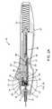
- FIG. 1is a perspective view of an embodiment according to the invention.
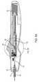
- FIG. 2Ais a cross-sectional side view of an embodiment according to the invention in a first configuration.
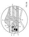
- FIG. 2Bis an area of detail of FIG. 2A .
- FIG. 3Ais a cross-sectional side view of an embodiment according to the invention in a second configuration.
- FIG. 3Bis an area of detail of FIG. 3A .
- FIG. 4Ais a cross-sectional side view of an embodiment according to the invention in a third configuration.
- FIG. 4Bis an area of detail of FIG. 4A .
- FIG. 5Ais a cross-sectional side view of an embodiment according to the invention in a fourth configuration.
- FIG. 5Bis an area of detail of FIG. 5A .
- actuation system 10When in use, actuation system 10 is releasably attached to a proximal end of an endolumenal implant delivery system such as catheter 19 , or a comparable implant delivery tool having a shaft and a lumen, such as a hypotube, or catheter body 18 .
- a pull wire 16is disposed axially in catheter body 18 .
- System 10is held and operated by a practitioner during a procedure to implant one or more devices into the vasculature of a patient.
- system 10includes a handle 20 which houses mechanisms for grasping a proximal end of the pull wire 16 , and then abruptly retracting the pull wire 16 upon actuation by a user. Operation may be effected by a single pull by the practitioner's thumb and the implant is thereby deployed in a decisive, consistent, and reliable manner regardless of variations in speed and force applied by the user.
- an implantis loaded into the catheter 19 or comparable implant tool (such as, for example, the coil delivery catheter described in commonly owned, copending application Ser. No. 12/498,752, previously incorporated herein by reference).
- a pull wire 16extends through the lumen of catheter body 18 .
- the proximal end of catheter body 18is positioned at the apex of a funnel 12 , which is formed in a distal end of handle 20 , and the proximal end of the pull wire is loaded through funnel 12 and into the distal end of handle 20 .
- Distal end of catheter 19is inserted into the body, and the implant is carried until the implant and the distal end of catheter 19 are properly positioned in a blood vessel or other body lumen, for deployment of the implant in the body.
- wireis used herein, it will be understood that any elongated filament of suitable mechanical properties and structure is included in the term.
- handle 20advantageously includes a finger groove 21 defined by the exterior of handle 20 .
- a triggerconfigured as a thumb grip 34 , which is axially movable along the exterior of handle 20 via a channel 34 ′ or comparable structure ( FIG. 2A ).
- Thumb grip 34may be pulled may be pulled in a proximal direction as indicated by the arrow in FIG. 1 in order to release or otherwise deploy the implant loaded from the distal end of the catheter 19 (as described in commonly owned, copending application Ser. No. 12/498,752, previously incorporated by reference).
- Thumb grip 34 and handle 20may be shaped as illustrated in FIG. 1 or otherwise suitably configured to optimize ergonomic functioning.
- handle 20may be of any dimensions suitable for optimal handling by a user.
- Handle 20may be manufactured from a suitable medical grade plastic, such as Santoprene medical grade Thermoplastic Vulcanizate available from ExxonMobil Chemical, or acrylonitrile butadiene styrene (ABS) available from Lustran. Suitable materials include materials that may be sterilized in ethylene oxide or radiation, or in an autoclave. Further, desirable materials include those that are injection moldable and recyclable.
- the external surfaces of handle 20are preferably smooth and non-abrasive.
- the internal components of handle 20may be manufactured from polycarbonate and silicone available from RTP Co. or similar materials and may additionally include stainless steel, rubber or other suitable materials.
- Manual actuation system 10may include additional elements, materials and coatings for securing the components and for smooth inter-operative engagement of the components.
- FIGS. 2A-5Billustrate “snapshots” taken throughout the sequence of operational steps of system 10 . They highlight the most significant transition points of the interaction of the components of system 10 , during the retraction of thumb grip 34 .
- a first phasecan be referred to as a “resting position”, in which thumb grip 34 is not retracted and lies in its distal-most position, as illustrated in FIG. 2A , and in detail in FIG. 2B .
- FIG. 3AA “grasping position” in which thumb grip 34 is slightly retracted in the proximal direction (indicated by the arrow) is illustrated in FIG. 3A , and in detail in FIG. 3B .
- thumb grip 34is pulled through a longer “priming phase”, until it reaches a latch release position ( FIGS. 4A-4B ).
- latch releasepull wire 16 is abruptly pulled proximally ( FIGS. 5A-5B ), and the system 10 returns to the initial resting position following release of thumb grip 34 .
- the pull wire 16is automatically released from the grabber and the handle is ready for use with another catheter or delivery device.
- handle 20The principle internal components of handle 20 are wire gripper or grabber 24 , slider 28 , and shuttle 36 .
- wire gripper or grabber 24In the “at rest” position, wire gripper or grabber 24 is lifted “open” for receiving pull wire 16 between grabber elements 25 and 27 which are mounted on shuttle 36 .
- grabber elements 25 and 27In the “grasping position” grabber elements 25 and 27 are allowed to close on the proximal end of pull wire 16 , thus coupling the pull wire to the shuttle 36 .
- the trigger, or thumb grip 34is proximally retracted to pull slider 28 axially along handle 20 , but shuttle 36 and grabber 24 remain latched to the handle 20 and stationary until slider 28 triggers release of the latch which allows the shuttle to be drawn in a proximal direction by a spring mechanism which, because the shuttle is coupled to grabber 24 , abruptly retracts pull wire 16 .
- grabber 24includes a rocker arm 22 pivotally connected to shuttle 36 via a pivot point 29 .
- a spring 23biases rocker arm 22 to rotate in a clockwise direction to a “closed position”.
- grabber 24is held “open” with grabber element 25 lifted away from grabber element 27 by a wedge 26 carried by slider 28 .
- thumb grip 34removes the wedge 26 from beneath the rocker arm 22 and allows grabber 24 to grasp the proximal end of wire 16 .
- FIG. 3Athe grasping configuration is illustrated in FIG. 3A and in detail in FIG. 3B .
- Slider 28is linked to thumb grip 34 .
- Slider 28has a wedge 26 . After slight retraction of thumb grip 34 , slider 28 travels axially, and wedge 26 also travels axially, out of nesting engagement with grabber 24 . In turn, retraction of wedge 26 permits spring 23 to bias rocker arm 22 pivotally about pivot point 29 .
- Grabber element 25 and grabber element 27can thereby engage or “grasp” wire 16 .
- the slider 28 , wedge 26 , and thumb grip 34are illustrated as a monolithic structure, they could be provided as separate components which are joined or connected by conventional techniques. For the purposes of the present invention, it is important only that they are sufficiently coupled so that they travel in unison as the thumb grip is retracted and later advanced.
- Button 52extends from latch member 50 , which is cut within a sidewall or otherwise disposed upon shuttle 36 .
- button 52rests against stop 48 .
- a trip 38is defined by the proximal end of wedge 26 .
- Trip 38travels proximally with slider 28 during retraction of slider 28 .
- trip 38acts to depress button 52 via latch member 50 , thereby releasing button 52 from its resting position against stop 48 . (See FIGS. 4A-4B ).
- button 52permits the spring action of extension spring 35 , which thereby ‘launches’ shuttle 36 in a proximal direction within handle 20 . (See FIGS. 5A-5B .) And because pull wire 16 is within the grasp of grabber 24 , this decisive retraction of shuttle 36 also decisively retracts pull wire 16 . And upon the decisive retraction of pull wire 16 , the implant (not pictured) is deployed.
- a compression spring 37is increasingly compressed, and compressive force increases within compression spring 37 .
- the usermay then release thumb grip 34 .
- the tension stored in compression spring 37acts to return slider 28 and shuttle 36 to a neutral position, shown in FIG. 2A .
- As full distal travel of the slider 28causes the wedge 26 to engage and lift the rocker arm 22 .
- the pull wire 16is released. This is both a safety feature as detachment of the actuation system 10 from the catheter or other delivery system reduces the risk of inadvertently disturbing the deployed implant as well as a convenience since the handle is then ready to repeat the foregoing process if desired.
Landscapes
- Health & Medical Sciences (AREA)
- Life Sciences & Earth Sciences (AREA)
- Engineering & Computer Science (AREA)
- Biomedical Technology (AREA)
- Veterinary Medicine (AREA)
- Animal Behavior & Ethology (AREA)
- Heart & Thoracic Surgery (AREA)
- Public Health (AREA)
- General Health & Medical Sciences (AREA)
- Pulmonology (AREA)
- Biophysics (AREA)
- Anesthesiology (AREA)
- Hematology (AREA)
- Oral & Maxillofacial Surgery (AREA)
- Vascular Medicine (AREA)
- Cardiology (AREA)
- Transplantation (AREA)
- Media Introduction/Drainage Providing Device (AREA)
Abstract
Description
Claims (24)
Priority Applications (3)
| Application Number | Priority Date | Filing Date | Title |
|---|---|---|---|
| US12/888,137US8911487B2 (en) | 2009-09-22 | 2010-09-22 | Manual actuation system for deployment of implant |
| US14/542,001US9615951B2 (en) | 2009-09-22 | 2014-11-14 | Manual actuation system for deployment of implant |
| US15/451,201US10299947B2 (en) | 2009-09-22 | 2017-03-06 | Manual actuation system for deployment of implant |
Applications Claiming Priority (2)
| Application Number | Priority Date | Filing Date | Title |
|---|---|---|---|
| US24478509P | 2009-09-22 | 2009-09-22 | |
| US12/888,137US8911487B2 (en) | 2009-09-22 | 2010-09-22 | Manual actuation system for deployment of implant |
Related Child Applications (1)
| Application Number | Title | Priority Date | Filing Date |
|---|---|---|---|
| US14/542,001ContinuationUS9615951B2 (en) | 2009-09-22 | 2014-11-14 | Manual actuation system for deployment of implant |
Publications (2)
| Publication Number | Publication Date |
|---|---|
| US20110238147A1 US20110238147A1 (en) | 2011-09-29 |
| US8911487B2true US8911487B2 (en) | 2014-12-16 |
Family
ID=43796185
Family Applications (3)
| Application Number | Title | Priority Date | Filing Date |
|---|---|---|---|
| US12/888,137Active2032-08-10US8911487B2 (en) | 2009-09-22 | 2010-09-22 | Manual actuation system for deployment of implant |
| US14/542,001ActiveUS9615951B2 (en) | 2009-09-22 | 2014-11-14 | Manual actuation system for deployment of implant |
| US15/451,201Active2031-04-20US10299947B2 (en) | 2009-09-22 | 2017-03-06 | Manual actuation system for deployment of implant |
Family Applications After (2)
| Application Number | Title | Priority Date | Filing Date |
|---|---|---|---|
| US14/542,001ActiveUS9615951B2 (en) | 2009-09-22 | 2014-11-14 | Manual actuation system for deployment of implant |
| US15/451,201Active2031-04-20US10299947B2 (en) | 2009-09-22 | 2017-03-06 | Manual actuation system for deployment of implant |
Country Status (2)
| Country | Link |
|---|---|
| US (3) | US8911487B2 (en) |
| WO (1) | WO2011038017A1 (en) |
Cited By (35)
| Publication number | Priority date | Publication date | Assignee | Title |
|---|---|---|---|---|
| US9615951B2 (en) | 2009-09-22 | 2017-04-11 | Penumbra, Inc. | Manual actuation system for deployment of implant |
| US9867964B2 (en) | 2015-04-23 | 2018-01-16 | Medtronic, Inc. | Interventional medical systems, assemblies, and construction methods |
| US9937322B2 (en) | 2015-04-23 | 2018-04-10 | Medtronic, Inc. | Assemblies and methods for deflectable shaft catheters |
| US10245167B2 (en) | 2015-01-29 | 2019-04-02 | Intact Vascular, Inc. | Delivery device and method of delivery |
| US10251739B2 (en) | 2013-03-15 | 2019-04-09 | Insera Therapeutics, Inc. | Thrombus aspiration using an operator-selectable suction pattern |
| USD847865S1 (en) | 2018-01-22 | 2019-05-07 | Insera Therapeutics, Inc. | Pump |
| US10390926B2 (en) | 2013-07-29 | 2019-08-27 | Insera Therapeutics, Inc. | Aspiration devices and methods |
| US10441449B1 (en) | 2018-05-30 | 2019-10-15 | Vesper Medical, Inc. | Rotary handle stent delivery system and method |
| US10449073B1 (en) | 2018-09-18 | 2019-10-22 | Vesper Medical, Inc. | Rotary handle stent delivery system and method |
| US10531883B1 (en) | 2018-07-20 | 2020-01-14 | Syntheon 2.0, LLC | Aspiration thrombectomy system and methods for thrombus removal with aspiration catheter |
| US10610392B2 (en) | 2015-01-29 | 2020-04-07 | Intact Vascular, Inc. | Delivery device and method of delivery |
| US10617846B2 (en)* | 2016-07-21 | 2020-04-14 | Redsmith, Inc. | Guidewire advancing device and method |
| US10716585B2 (en) | 2016-03-17 | 2020-07-21 | Trice Medical, Inc. | Clot evacuation and visualization devices and methods of use |
| US10813780B2 (en) | 2018-08-08 | 2020-10-27 | DePuy Synthes Products, Inc. | Intraluminal implant delivery system and method |
| US10874402B2 (en) | 2017-10-10 | 2020-12-29 | Boston Scientific Scimed, Inc. | Detachable RF energized occlusive device |
| US10898356B2 (en) | 2015-01-29 | 2021-01-26 | Intact Vascular, Inc. | Delivery device and method of delivery |
| US20210077091A1 (en)* | 2018-05-29 | 2021-03-18 | Smith & Nephew, Inc. | Suture passer with locking actuator |
| US10993824B2 (en) | 2016-01-01 | 2021-05-04 | Intact Vascular, Inc. | Delivery device and method of delivery |
| US11000287B2 (en) | 2017-08-15 | 2021-05-11 | Boston Scientific Scimed, Inc. | Occlusive medical device system |
| USD919804S1 (en)* | 2014-10-13 | 2021-05-18 | W. L. Gore & Associates, Inc. | Handle for medical delivery apparatus device |
| US11154412B2 (en) | 2018-02-01 | 2021-10-26 | Boston Scientific Scimed, Inc. | Medical device release system |
| US20210353907A1 (en)* | 2020-05-15 | 2021-11-18 | Medtronic, Inc. | Constructions for a deflectable shaft catheter |
| US11191927B2 (en) | 2017-07-31 | 2021-12-07 | Boston Scientific Scimed, Inc. | Dilator with engagement region |
| US11219541B2 (en) | 2020-05-21 | 2022-01-11 | Vesper Medical, Inc. | Wheel lock for thumbwheel actuated device |
| US11273285B2 (en) | 2019-02-07 | 2022-03-15 | DePuy Synthes Products, Inc. | Ancillary device for detaching implants |
| US11284902B2 (en) | 2018-02-01 | 2022-03-29 | Boston Scientific Scimed, Inc. | Method of making a vascular occlusion device |
| USD959659S1 (en) | 2019-05-10 | 2022-08-02 | DePuy Synthes Products, Inc. | Implant release handle |
| US11524143B2 (en)* | 2019-07-15 | 2022-12-13 | Medtronic, Inc. | Catheter with distal and proximal fixation members |
| US11524139B2 (en) | 2019-07-15 | 2022-12-13 | Medtronic, Inc. | Catheter with active return curve |
| US11547446B2 (en) | 2014-01-13 | 2023-01-10 | Trice Medical, Inc. | Fully integrated, disposable tissue visualization device |
| US11660218B2 (en) | 2017-07-26 | 2023-05-30 | Intact Vascular, Inc. | Delivery device and method of delivery |
| US11672946B2 (en) | 2019-09-24 | 2023-06-13 | Boston Scientific Scimed, Inc. | Protection and actuation mechanism for controlled release of implantable embolic devices |
| US11701123B2 (en) | 2020-08-21 | 2023-07-18 | Shape Memory Medical, Inc. | Mechanical detachment system for transcatheter devices |
| US20230291185A1 (en)* | 2022-01-31 | 2023-09-14 | Lassol Ltd. | Threaded grasping system and method |
| US12220139B2 (en) | 2022-03-20 | 2025-02-11 | Von Vascular, Inc. | System, devices and methods for removing obstructions in body lumens |
Families Citing this family (176)
| Publication number | Priority date | Publication date | Assignee | Title |
|---|---|---|---|---|
| EP1951129B1 (en) | 2005-10-19 | 2012-11-21 | Pulsar Vascular, Inc. | Methods and systems for endovascularly clipping and repairing lumen and tissue defects |
| US9402707B2 (en) | 2008-07-22 | 2016-08-02 | Neuravi Limited | Clot capture systems and associated methods |
| WO2010028314A1 (en) | 2008-09-05 | 2010-03-11 | Pulsar Vascular, Inc. | Systems and methods for supporting or occluding a physiological opening or cavity |
| ES2683943T3 (en) | 2010-10-22 | 2018-09-28 | Neuravi Limited | Clot capture and removal system |
| FI122579B (en)* | 2010-10-29 | 2012-03-30 | Bayer Oy | inserter |
| EP4566553A3 (en) | 2011-03-09 | 2025-08-06 | Neuravi Limited | A clot retrieval device for removing occlusive clot from a blood vessel |
| US11259824B2 (en) | 2011-03-09 | 2022-03-01 | Neuravi Limited | Clot retrieval device for removing occlusive clot from a blood vessel |
| US12076037B2 (en) | 2011-03-09 | 2024-09-03 | Neuravi Limited | Systems and methods to restore perfusion to a vessel |
| CN103582460B (en) | 2011-06-03 | 2019-03-19 | 帕尔萨维斯库勒公司 | Aneurysm devices and related systems and methods with additional anchoring mechanism |
| US10028858B2 (en) | 2011-07-11 | 2018-07-24 | Medicines360 | Intrauterine systems, IUD insertion devices, and related methods and kits therefor |
| EP4101399B1 (en) | 2011-08-05 | 2025-04-09 | Route 92 Medical, Inc. | System for treatment of acute ischemic stroke |
| US10779855B2 (en) | 2011-08-05 | 2020-09-22 | Route 92 Medical, Inc. | Methods and systems for treatment of acute ischemic stroke |
| US9119625B2 (en) | 2011-10-05 | 2015-09-01 | Pulsar Vascular, Inc. | Devices, systems and methods for enclosing an anatomical opening |
| US10945756B2 (en)* | 2013-03-01 | 2021-03-16 | Catch Medical, Llc | Device of inserting and controlling a snare |
| US10561509B2 (en) | 2013-03-13 | 2020-02-18 | DePuy Synthes Products, Inc. | Braided stent with expansion ring and method of delivery |
| US10603157B2 (en) | 2013-03-13 | 2020-03-31 | DePuy Synthes Products, Inc. | Braid implant delivery and retraction device with distal engagement |
| WO2014140092A2 (en) | 2013-03-14 | 2014-09-18 | Neuravi Limited | Devices and methods for removal of acute blockages from blood vessels |
| US9433429B2 (en) | 2013-03-14 | 2016-09-06 | Neuravi Limited | Clot retrieval devices |
| ES2708786T3 (en) | 2013-03-14 | 2019-04-11 | Neuravi Ltd | Clot recovery device to remove occlusive clots from a blood vessel |
| US9265512B2 (en) | 2013-12-23 | 2016-02-23 | Silk Road Medical, Inc. | Transcarotid neurovascular catheter |
| US10285720B2 (en) | 2014-03-11 | 2019-05-14 | Neuravi Limited | Clot retrieval system for removing occlusive clot from a blood vessel |
| US11154302B2 (en) | 2014-03-31 | 2021-10-26 | DePuy Synthes Products, Inc. | Aneurysm occlusion device |
| US11076860B2 (en) | 2014-03-31 | 2021-08-03 | DePuy Synthes Products, Inc. | Aneurysm occlusion device |
| US10159819B2 (en)* | 2014-04-24 | 2018-12-25 | Medtronic Vascular Galway | Control module for delivery systems |
| JP6595513B2 (en) | 2014-06-13 | 2019-10-23 | ニューラヴィ・リミテッド | Device for removal of acute occlusions from blood vessels |
| US10265086B2 (en) | 2014-06-30 | 2019-04-23 | Neuravi Limited | System for removing a clot from a blood vessel |
| US9918718B2 (en) | 2014-08-08 | 2018-03-20 | DePuy Synthes Products, Inc. | Embolic coil delivery system with retractable mechanical release mechanism |
| US10206796B2 (en) | 2014-08-27 | 2019-02-19 | DePuy Synthes Products, Inc. | Multi-strand implant with enhanced radiopacity |
| US9782178B2 (en) | 2014-09-19 | 2017-10-10 | DePuy Synthes Products, Inc. | Vasculature occlusion device detachment system with tapered corewire and heater activated fiber detachment |
| US11253278B2 (en) | 2014-11-26 | 2022-02-22 | Neuravi Limited | Clot retrieval system for removing occlusive clot from a blood vessel |
| EP3682821B1 (en) | 2014-11-26 | 2022-05-11 | Neuravi Limited | A clot retrieval device for removing an occlusive clot from a blood vessel |
| US10617435B2 (en) | 2014-11-26 | 2020-04-14 | Neuravi Limited | Clot retrieval device for removing clot from a blood vessel |
| US10426497B2 (en) | 2015-07-24 | 2019-10-01 | Route 92 Medical, Inc. | Anchoring delivery system and methods |
| CN119949953A (en) | 2015-02-04 | 2025-05-09 | 92号医疗公司 | Intravascular access system, dilator and system including dilator |
| US11065019B1 (en) | 2015-02-04 | 2021-07-20 | Route 92 Medical, Inc. | Aspiration catheter systems and methods of use |
| USD799033S1 (en) | 2015-04-02 | 2017-10-03 | W. L. Gore & Associates, Inc. | Catheter handle |
| USD790057S1 (en) | 2015-04-02 | 2017-06-20 | W. L. Gore & Associates, Inc. | Handle design for catheter Y-hub with dual side ports |
| WO2017147493A1 (en) | 2016-02-24 | 2017-08-31 | Incept, Llc | Enhanced flexibility neurovascular catheter |
| US10285710B2 (en) | 2016-06-01 | 2019-05-14 | DePuy Synthes Products, Inc. | Endovascular detachment system with flexible distal end and heater activated detachment |
| EP3500191B1 (en) | 2016-08-17 | 2020-09-23 | Neuravi Limited | A clot retrieval system for removing occlusive clot from a blood vessel |
| US10076428B2 (en) | 2016-08-25 | 2018-09-18 | DePuy Synthes Products, Inc. | Expansion ring for a braided stent |
| EP3509509B1 (en) | 2016-09-06 | 2021-03-31 | Neuravi Limited | A clot retrieval device for removing occlusive clot from a blood vessel |
| US10292851B2 (en) | 2016-09-30 | 2019-05-21 | DePuy Synthes Products, Inc. | Self-expanding device delivery apparatus with dual function bump |
| US10517708B2 (en) | 2016-10-26 | 2019-12-31 | DePuy Synthes Products, Inc. | Multi-basket clot capturing device |
| US10478599B2 (en) | 2016-11-17 | 2019-11-19 | Vascugenix LLC | Compression torque device |
| USD810933S1 (en)* | 2016-11-17 | 2018-02-20 | Vascugenix LLC | Compression torque device |
| JP7264581B2 (en) | 2017-01-06 | 2023-04-25 | インセプト、リミテッド、ライアビリティ、カンパニー | Antithrombotic coating for aneurysm treatment devices |
| CN110392591B (en) | 2017-01-10 | 2022-06-03 | 92号医疗公司 | Aspiration catheter system and method of use |
| US10905853B2 (en) | 2017-01-17 | 2021-02-02 | DePuy Synthes Products, Inc. | System and method for delivering a catheter |
| US10864350B2 (en) | 2017-01-20 | 2020-12-15 | Route 92 Medical, Inc. | Single operator intracranial medical device delivery systems and methods of use |
| US10881497B2 (en) | 2017-01-26 | 2021-01-05 | DePuy Synthes Products, Inc. | Composite vascular flow diverter |
| CN110545739A (en) | 2017-02-23 | 2019-12-06 | 德普伊新特斯产品公司 | aneurysm devices and delivery systems |
| US11116509B2 (en) | 2017-11-10 | 2021-09-14 | Avantec Vascular Corporation | System and method for delivering an embolic device |
| US10806462B2 (en) | 2017-12-21 | 2020-10-20 | DePuy Synthes Products, Inc. | Implantable medical device detachment system with split tube and cylindrical coupling |
| US10751065B2 (en) | 2017-12-22 | 2020-08-25 | DePuy Synthes Products, Inc. | Aneurysm device and delivery system |
| US10905430B2 (en) | 2018-01-24 | 2021-02-02 | DePuy Synthes Products, Inc. | Aneurysm device and delivery system |
| EP3755237B1 (en) | 2018-02-20 | 2022-04-27 | Boston Scientific Scimed Inc. | Medical device release system |
| US10786259B2 (en) | 2018-03-30 | 2020-09-29 | DePuy Synthes Products, Inc. | Split balloon assist device and method for using the same |
| US10918390B2 (en) | 2018-03-30 | 2021-02-16 | DePuy Synthes Products, Inc. | Helical balloon assist device and method for using the same |
| US10806461B2 (en) | 2018-04-27 | 2020-10-20 | DePuy Synthes Products, Inc. | Implantable medical device detachment system with split tube |
| AU2019262972B2 (en) | 2018-05-01 | 2025-02-27 | Incept, Llc | Devices and methods for removing obstructive material from an intravascular site |
| US11395665B2 (en) | 2018-05-01 | 2022-07-26 | Incept, Llc | Devices and methods for removing obstructive material, from an intravascular site |
| JP7616642B2 (en) | 2018-05-17 | 2025-01-17 | ルート92メディカル・インコーポレイテッド | Suction catheter system and method of use |
| US11596412B2 (en) | 2018-05-25 | 2023-03-07 | DePuy Synthes Products, Inc. | Aneurysm device and delivery system |
| US11058430B2 (en) | 2018-05-25 | 2021-07-13 | DePuy Synthes Products, Inc. | Aneurysm device and delivery system |
| US10939915B2 (en) | 2018-05-31 | 2021-03-09 | DePuy Synthes Products, Inc. | Aneurysm device and delivery system |
| US10667833B2 (en) | 2018-06-08 | 2020-06-02 | Neuravi Limited | Guidewire with an atraumatic clot-circumventing configured distal end for use in an endovascular medical system |
| US10898216B2 (en) | 2018-06-13 | 2021-01-26 | DePuy Synthes Products, Inc. | Vasculature obstruction capture device |
| US11517335B2 (en) | 2018-07-06 | 2022-12-06 | Incept, Llc | Sealed neurovascular extendable catheter |
| US11471582B2 (en) | 2018-07-06 | 2022-10-18 | Incept, Llc | Vacuum transfer tool for extendable catheter |
| AU2019204522A1 (en) | 2018-07-30 | 2020-02-13 | DePuy Synthes Products, Inc. | Systems and methods of manufacturing and using an expansion ring |
| US10905431B2 (en) | 2018-08-03 | 2021-02-02 | DePuy Synthes Products, Inc. | Spiral delivery system for embolic braid |
| US10278848B1 (en) | 2018-08-06 | 2019-05-07 | DePuy Synthes Products, Inc. | Stent delivery with expansion assisting delivery wire |
| US10456280B1 (en) | 2018-08-06 | 2019-10-29 | DePuy Synthes Products, Inc. | Systems and methods of using a braided implant |
| US11051825B2 (en) | 2018-08-08 | 2021-07-06 | DePuy Synthes Products, Inc. | Delivery system for embolic braid |
| US10842498B2 (en) | 2018-09-13 | 2020-11-24 | Neuravi Limited | Systems and methods of restoring perfusion to a vessel |
| EP3626212A3 (en) | 2018-09-20 | 2020-07-22 | DePuy Synthes Products, Inc. | Stent with shaped wires |
| US11123077B2 (en) | 2018-09-25 | 2021-09-21 | DePuy Synthes Products, Inc. | Intrasaccular device positioning and deployment system |
| US11406416B2 (en) | 2018-10-02 | 2022-08-09 | Neuravi Limited | Joint assembly for vasculature obstruction capture device |
| US11253287B2 (en) | 2018-10-04 | 2022-02-22 | Neuravi Limited | Retrograde blood flow occlusion flushing device |
| US11076861B2 (en) | 2018-10-12 | 2021-08-03 | DePuy Synthes Products, Inc. | Folded aneurysm treatment device and delivery method |
| US11147562B2 (en) | 2018-12-12 | 2021-10-19 | DePuy Synthes Products, Inc. | Systems and methods for embolic implant detachment |
| US11406392B2 (en) | 2018-12-12 | 2022-08-09 | DePuy Synthes Products, Inc. | Aneurysm occluding device for use with coagulating agents |
| US11272939B2 (en) | 2018-12-18 | 2022-03-15 | DePuy Synthes Products, Inc. | Intrasaccular flow diverter for treating cerebral aneurysms |
| US11039944B2 (en) | 2018-12-27 | 2021-06-22 | DePuy Synthes Products, Inc. | Braided stent system with one or more expansion rings |
| US11684501B2 (en) | 2019-01-14 | 2023-06-27 | Cook Medical Technologies Llc | Multipurpose handle |
| US11134953B2 (en) | 2019-02-06 | 2021-10-05 | DePuy Synthes Products, Inc. | Adhesive cover occluding device for aneurysm treatment |
| ES2910600T3 (en) | 2019-03-04 | 2022-05-12 | Neuravi Ltd | Powered Clot Recovery Catheter |
| US11382633B2 (en) | 2019-03-06 | 2022-07-12 | DePuy Synthes Products, Inc. | Strut flow diverter for cerebral aneurysms and methods for preventing strut entanglement |
| US11337706B2 (en) | 2019-03-27 | 2022-05-24 | DePuy Synthes Products, Inc. | Aneurysm treatment device |
| US11185334B2 (en) | 2019-03-28 | 2021-11-30 | DePuy Synthes Products, Inc. | Single lumen reduced profile occlusion balloon catheter |
| US11766539B2 (en) | 2019-03-29 | 2023-09-26 | Incept, Llc | Enhanced flexibility neurovascular catheter |
| US11051928B2 (en) | 2019-04-11 | 2021-07-06 | Neuravi Limited | Floating carotid filter |
| US11931522B2 (en) | 2019-05-09 | 2024-03-19 | Neuravi Limited | Inflation lumen kink protection and balloon profile |
| US11571553B2 (en) | 2019-05-09 | 2023-02-07 | Neuravi Limited | Balloon guide catheter with thermally expandable material |
| US11957855B2 (en) | 2019-05-09 | 2024-04-16 | Neuravi Limited | Balloon guide catheter with positive venting of residual air |
| US11607531B2 (en) | 2019-05-09 | 2023-03-21 | Neuravi Limited | Balloon catheter with venting of residual air in a proximal direction |
| US11672542B2 (en) | 2019-05-21 | 2023-06-13 | DePuy Synthes Products, Inc. | Aneurysm treatment with pushable ball segment |
| US10653425B1 (en) | 2019-05-21 | 2020-05-19 | DePuy Synthes Products, Inc. | Layered braided aneurysm treatment device |
| US11607226B2 (en) | 2019-05-21 | 2023-03-21 | DePuy Synthes Products, Inc. | Layered braided aneurysm treatment device with corrugations |
| US11497504B2 (en) | 2019-05-21 | 2022-11-15 | DePuy Synthes Products, Inc. | Aneurysm treatment with pushable implanted braid |
| US11602350B2 (en) | 2019-12-05 | 2023-03-14 | DePuy Synthes Products, Inc. | Intrasaccular inverting braid with highly flexible fill material |
| US11278292B2 (en) | 2019-05-21 | 2022-03-22 | DePuy Synthes Products, Inc. | Inverting braided aneurysm treatment system and method |
| US11413046B2 (en) | 2019-05-21 | 2022-08-16 | DePuy Synthes Products, Inc. | Layered braided aneurysm treatment device |
| US11109939B2 (en) | 2019-06-14 | 2021-09-07 | DePuy Synthes Products, Inc. | Intravascular devices with radiopaque body markers |
| US11406403B2 (en) | 2019-06-14 | 2022-08-09 | Neuravi Limited | Visibility of mechanical thrombectomy device during diagnostic imaging |
| US11253265B2 (en) | 2019-06-18 | 2022-02-22 | DePuy Synthes Products, Inc. | Pull wire detachment for intravascular devices |
| US11207494B2 (en) | 2019-07-03 | 2021-12-28 | DePuy Synthes Products, Inc. | Medical device delivery member with flexible stretch resistant distal portion |
| US11426174B2 (en) | 2019-10-03 | 2022-08-30 | DePuy Synthes Products, Inc. | Medical device delivery member with flexible stretch resistant mechanical release |
| US11266427B2 (en) | 2019-07-10 | 2022-03-08 | Neuravi Limited | Self-expanding intravascular medical device |
| US11266426B2 (en) | 2019-07-10 | 2022-03-08 | DePuy Synthes Products, Inc. | Streamlined treatment of clot removal, angioplasty and prevention of restenosis using a single integrated intravascular device |
| US11395675B2 (en) | 2019-07-11 | 2022-07-26 | DePuy Synthes Products, Inc. | Clot retriever cleaning for reinsertion |
| EP3791815B1 (en) | 2019-09-11 | 2024-06-26 | Neuravi Limited | Expandable mouth catheter |
| US11439403B2 (en) | 2019-09-17 | 2022-09-13 | DePuy Synthes Products, Inc. | Embolic coil proximal connecting element and stretch resistant fiber |
| US12376859B2 (en) | 2019-09-17 | 2025-08-05 | DePuy Synthes Products, Inc. | Embolic coil proximal connecting element and stretch resistant fiber |
| US11134859B2 (en) | 2019-10-15 | 2021-10-05 | Imperative Care, Inc. | Systems and methods for multivariate stroke detection |
| US11712231B2 (en) | 2019-10-29 | 2023-08-01 | Neuravi Limited | Proximal locking assembly design for dual stent mechanical thrombectomy device |
| US20210128183A1 (en) | 2019-10-31 | 2021-05-06 | Neuravi Limited | Thrombectomy and stenting system |
| US11376013B2 (en) | 2019-11-18 | 2022-07-05 | DePuy Synthes Products, Inc. | Implant delivery system with braid cup formation |
| US11628282B2 (en) | 2019-11-25 | 2023-04-18 | Neuravi Limited | No preparation balloon guide catheter |
| US11839725B2 (en) | 2019-11-27 | 2023-12-12 | Neuravi Limited | Clot retrieval device with outer sheath and inner catheter |
| US11779364B2 (en) | 2019-11-27 | 2023-10-10 | Neuravi Limited | Actuated expandable mouth thrombectomy catheter |
| US11517340B2 (en) | 2019-12-03 | 2022-12-06 | Neuravi Limited | Stentriever devices for removing an occlusive clot from a vessel and methods thereof |
| US11382634B2 (en) | 2019-12-18 | 2022-07-12 | Avantec Vascular Corporation | Embolic device suited for ease of delivery and placement |
| US11638637B2 (en) | 2019-12-18 | 2023-05-02 | Imperative Care, Inc. | Method of removing embolic material with thrombus engagement tool |
| EP4076611A4 (en) | 2019-12-18 | 2023-11-15 | Imperative Care, Inc. | Methods and systems for treating venous thromboembolic disease |
| US11457926B2 (en) | 2019-12-18 | 2022-10-04 | DePuy Synthes Products, Inc. | Implant having an intrasaccular section and intravascular section |
| US20210316127A1 (en) | 2019-12-18 | 2021-10-14 | Imperative Care, Inc. | Hemostasis valve |
| US11457922B2 (en) | 2020-01-22 | 2022-10-04 | DePuy Synthes Products, Inc. | Medical device delivery member with flexible stretch resistant distal portion |
| US11992241B2 (en) | 2020-01-31 | 2024-05-28 | DePuy Synthes Products, Inc. | System to assist delivery of a mechanical intravascular treatment device |
| US11957354B2 (en) | 2020-02-10 | 2024-04-16 | DePuy Synthes Products, Inc. | Aneurysm implant support device |
| US11432822B2 (en) | 2020-02-14 | 2022-09-06 | DePuy Synthes Products, Inc. | Intravascular implant deployment system |
| US11944327B2 (en) | 2020-03-05 | 2024-04-02 | Neuravi Limited | Expandable mouth aspirating clot retrieval catheter |
| US11633198B2 (en) | 2020-03-05 | 2023-04-25 | Neuravi Limited | Catheter proximal joint |
| CN113747934B (en) | 2020-03-10 | 2024-07-09 | 因普瑞缇夫护理公司 | Enhanced flexibility neurovascular catheter |
| US11883043B2 (en) | 2020-03-31 | 2024-01-30 | DePuy Synthes Products, Inc. | Catheter funnel extension |
| US11759217B2 (en) | 2020-04-07 | 2023-09-19 | Neuravi Limited | Catheter tubular support |
| US11717308B2 (en) | 2020-04-17 | 2023-08-08 | Neuravi Limited | Clot retrieval device for removing heterogeneous clots from a blood vessel |
| US11871946B2 (en) | 2020-04-17 | 2024-01-16 | Neuravi Limited | Clot retrieval device for removing clot from a blood vessel |
| US11730501B2 (en) | 2020-04-17 | 2023-08-22 | Neuravi Limited | Floating clot retrieval device for removing clots from a blood vessel |
| US11523831B2 (en) | 2020-04-30 | 2022-12-13 | DePuy Synthes Products, Inc. | Intrasaccular flow diverter |
| US11737771B2 (en) | 2020-06-18 | 2023-08-29 | Neuravi Limited | Dual channel thrombectomy device |
| US11937836B2 (en) | 2020-06-22 | 2024-03-26 | Neuravi Limited | Clot retrieval system with expandable clot engaging framework |
| US11439418B2 (en) | 2020-06-23 | 2022-09-13 | Neuravi Limited | Clot retrieval device for removing clot from a blood vessel |
| US11395669B2 (en) | 2020-06-23 | 2022-07-26 | Neuravi Limited | Clot retrieval device with flexible collapsible frame |
| US11951026B2 (en) | 2020-06-30 | 2024-04-09 | DePuy Synthes Products, Inc. | Implantable medical device detachment system with flexible braid section |
| US20220031341A1 (en) | 2020-07-29 | 2022-02-03 | Neuravi Limited | Adhesive-Free Bonded Balloon for a Balloon Guide Catheter With Minimal Outer Profile |
| US11207497B1 (en) | 2020-08-11 | 2021-12-28 | Imperative Care, Inc. | Catheter with enhanced tensile strength |
| US11864781B2 (en) | 2020-09-23 | 2024-01-09 | Neuravi Limited | Rotating frame thrombectomy device |
| WO2022076893A1 (en) | 2020-10-09 | 2022-04-14 | Route 92 Medical, Inc. | Aspiration catheter systems and methods of use |
| USD995761S1 (en)* | 2020-11-12 | 2023-08-15 | Healthium Medtech Ltd. | Meniscus repair device |
| US11826520B2 (en) | 2020-12-08 | 2023-11-28 | DePuy Synthes Products, Inc. | Catheter designs for enhanced column strength |
| US11786698B2 (en) | 2020-12-08 | 2023-10-17 | DePuy Synthes Products, Inc. | Catheter with textured surface |
| US11937837B2 (en) | 2020-12-29 | 2024-03-26 | Neuravi Limited | Fibrin rich / soft clot mechanical thrombectomy device |
| US12029442B2 (en) | 2021-01-14 | 2024-07-09 | Neuravi Limited | Systems and methods for a dual elongated member clot retrieval apparatus |
| US11872354B2 (en) | 2021-02-24 | 2024-01-16 | Neuravi Limited | Flexible catheter shaft frame with seam |
| US12064130B2 (en) | 2021-03-18 | 2024-08-20 | Neuravi Limited | Vascular obstruction retrieval device having sliding cages pinch mechanism |
| US11974764B2 (en) | 2021-06-04 | 2024-05-07 | Neuravi Limited | Self-orienting rotating stentriever pinching cells |
| US11998213B2 (en) | 2021-07-14 | 2024-06-04 | DePuy Synthes Products, Inc. | Implant delivery with modified detachment feature and pull wire engagement |
| US20230052862A1 (en) | 2021-08-12 | 2023-02-16 | Imperative Care, Inc. | Sterile packaging assembly for robotic interventional device |
| US12369920B2 (en) | 2021-09-22 | 2025-07-29 | DePuy Synthes Products, Inc. | Introducer sheath having an intentional friction zone to hold in position a delivery system suitable for implantable intravascular devices |
| US11937839B2 (en) | 2021-09-28 | 2024-03-26 | Neuravi Limited | Catheter with electrically actuated expandable mouth |
| USD1077996S1 (en) | 2021-10-18 | 2025-06-03 | Imperative Care, Inc. | Inline fluid filter |
| US12011186B2 (en) | 2021-10-28 | 2024-06-18 | Neuravi Limited | Bevel tip expandable mouth catheter with reinforcing ring |
| WO2023072729A1 (en)* | 2021-11-01 | 2023-05-04 | Vascomed Gmbh | Catheterization device |
| US11751881B2 (en) | 2021-11-26 | 2023-09-12 | DePuy Synthes Products, Inc. | Securement wire withstanding forces during deployment of implantable intravascular treatment device using a delivery and detachment system |
| US11937824B2 (en) | 2021-12-30 | 2024-03-26 | DePuy Synthes Products, Inc. | Implant detachment systems with a modified pull wire |
| US11844490B2 (en) | 2021-12-30 | 2023-12-19 | DePuy Synthes Products, Inc. | Suture linkage for inhibiting premature embolic implant deployment |
| US12220131B2 (en) | 2022-01-06 | 2025-02-11 | DePuy Synthes Products, Inc. | Delivery and detachment system imposing a friction force on a securement wire to minimize movement of an implantable intravascular device |
| US12011171B2 (en) | 2022-01-06 | 2024-06-18 | DePuy Synthes Products, Inc. | Systems and methods for inhibiting premature embolic implant deployment |
| US11937825B2 (en) | 2022-03-02 | 2024-03-26 | DePuy Synthes Products, Inc. | Hook wire for preventing premature embolic implant detachment |
| US12137915B2 (en) | 2022-03-03 | 2024-11-12 | DePuy Synthes Products, Inc. | Elongating wires for inhibiting premature implant detachment |
| US11937826B2 (en) | 2022-03-14 | 2024-03-26 | DePuy Synthes Products, Inc. | Proximal link wire for preventing premature implant detachment |
| CN114699132B (en)* | 2022-03-31 | 2025-01-24 | 北京美中双和医疗器械股份有限公司 | A surgical implant mechanical release device and release method |
| US12402886B2 (en) | 2022-06-23 | 2025-09-02 | DePuy Synthes Products, Inc. | Detachment indicator for implant deployment |
| US12396730B2 (en) | 2022-09-28 | 2025-08-26 | DePuy Synthes Products, Inc. | Braided implant with detachment mechanism |
Citations (62)
| Publication number | Priority date | Publication date | Assignee | Title |
|---|---|---|---|---|
| US2934318A (en)* | 1957-11-21 | 1960-04-26 | United States Steel Corp | Strapping-actuated gripper for tensioner |
| US3018531A (en)* | 1960-09-12 | 1962-01-30 | Arsenault Jean Jacques | Line puller |
| US3312128A (en)* | 1965-05-07 | 1967-04-04 | Lawrence W Wasson | Wire gripper |
| US3467102A (en)* | 1967-04-18 | 1969-09-16 | Edwards Lab Inc | Leader type catheter |
| US4799496A (en)* | 1987-06-03 | 1989-01-24 | Lake Region Manufacturing Company, Inc. | Guide wire handle |
| US4860776A (en)* | 1985-05-02 | 1989-08-29 | Instant Defence Inc. | Shield for a person |
| US5219332A (en)* | 1992-11-30 | 1993-06-15 | Merit Medical Systems, Inc. | Rotation tool for medical guidewire |
| US5261916A (en) | 1991-12-12 | 1993-11-16 | Target Therapeutics | Detachable pusher-vasoocclusive coil assembly with interlocking ball and keyway coupling |
| US5273042A (en)* | 1987-10-28 | 1993-12-28 | Medical Parameters, Inc. | Guidewire advancement method |
| US5304195A (en) | 1991-12-12 | 1994-04-19 | Target Therapeutics, Inc. | Detachable pusher-vasoocclusive coil assembly with interlocking coupling |
| US5312338A (en)* | 1992-11-30 | 1994-05-17 | Merit Medical Systems, Inc. | Rotation tool for medical guidewire |
| US5325746A (en)* | 1991-09-27 | 1994-07-05 | Cook Incorporated | Wire guide control handle |
| US5325868A (en)* | 1993-05-04 | 1994-07-05 | Kimmelstiel Carey D | Self-gripping medical wire torquer |
| US5350397A (en) | 1992-11-13 | 1994-09-27 | Target Therapeutics, Inc. | Axially detachable embolic coil assembly |
| US5431370A (en)* | 1994-03-28 | 1995-07-11 | Verkuylen; Donald G. | Fish tape tugger |
| US5443477A (en)* | 1994-02-10 | 1995-08-22 | Stentco, Inc. | Apparatus and method for deployment of radially expandable stents by a mechanical linkage |
| US5499990A (en)* | 1992-05-23 | 1996-03-19 | Forschungszentrum Karlsruhe Gmbh | Suturing instrument |
| US5579780A (en)* | 1994-10-11 | 1996-12-03 | Zadini; Filiberto P. | Manual guidewire placement device |
| US5749371A (en)* | 1995-10-06 | 1998-05-12 | Zadini; Filiberto P. | Automatic guidewire placement device for medical catheters |
| US5782909A (en)* | 1993-08-05 | 1998-07-21 | Endovascular Technologies, Inc. | Multicapsule intraluminal grafting system and method |
| US5800454A (en) | 1997-03-17 | 1998-09-01 | Sarcos, Inc. | Catheter deliverable coiled wire thromboginic apparatus and method |
| US5853418A (en) | 1995-06-30 | 1998-12-29 | Target Therapeutics, Inc. | Stretch resistant vaso-occlusive coils (II) |
| US5891058A (en) | 1996-08-15 | 1999-04-06 | Kaneka Medix Corporation | Coiled embolizing material |
| US5895391A (en) | 1996-09-27 | 1999-04-20 | Target Therapeutics, Inc. | Ball lock joint and introducer for vaso-occlusive member |
| US5902305A (en)* | 1996-07-11 | 1999-05-11 | Aesculap Ag & Co. Kg | Surgical tensioning device |
| US5935141A (en)* | 1997-10-30 | 1999-08-10 | Partisan Management Group | Interventional cardiology instrument controlled from an intracoronary reference |
| US5968052A (en)* | 1996-11-27 | 1999-10-19 | Scimed Life Systems Inc. | Pull back stent delivery system with pistol grip retraction handle |
| US6039744A (en)* | 1997-12-19 | 2000-03-21 | B. Braun Celsa | Assembly for positioning an implant in an internal passageway of a body |
| US6042585A (en)* | 1997-05-01 | 2000-03-28 | Linvatec Corporation | Surgical wire driver with one-handed gripping attachment |
| US6231564B1 (en)* | 1995-09-29 | 2001-05-15 | Medtronic Ave, Inc. | Storable guidewire system |
| US6344044B1 (en)* | 2000-02-11 | 2002-02-05 | Edwards Lifesciences Corp. | Apparatus and methods for delivery of intraluminal prosthesis |
| US6391030B1 (en)* | 1997-08-26 | 2002-05-21 | Spinal Concepts, Inc. | Surgical cable system and method |
| US6488700B2 (en) | 1999-02-26 | 2002-12-03 | Vascular Architects, Inc. | Endoluminal prosthesis placing method |
| US6533772B1 (en)* | 2000-04-07 | 2003-03-18 | Innex Corporation | Guide wire torque device |
| US6544267B1 (en)* | 1998-01-26 | 2003-04-08 | Orthodyne, Inc. | Tissue anchoring system and method |
| US6551340B1 (en) | 1998-10-09 | 2003-04-22 | Board Of Regents The University Of Texas System | Vasoocclusion coil device having a core therein |
| US6599296B1 (en)* | 2001-07-27 | 2003-07-29 | Advanced Cardiovascular Systems, Inc. | Ratcheting handle for intraluminal catheter systems |
| US6663588B2 (en)* | 2000-11-29 | 2003-12-16 | C.R. Bard, Inc. | Active counterforce handle for use in bidirectional deflectable tip instruments |
| US20050192621A1 (en) | 1999-06-04 | 2005-09-01 | Scimed Life Systems, Inc. | Polymer covered vaso-occlusive devices and methods of producing such devices |
| US20070121405A1 (en) | 2005-11-28 | 2007-05-31 | Renesas Technology Corp. | Semiconductor memory device |
| EP1797833A1 (en) | 2005-12-14 | 2007-06-20 | Cordis Neurovascular, Inc. | Stretch resistant embolic coil delivery system with mechanical release mechanism |
| US20070179520A1 (en) | 2006-01-31 | 2007-08-02 | Stephen West | Embolic device delivery system |
| US20070293928A1 (en) | 2006-06-14 | 2007-12-20 | Damian Tomlin | Retrieval device with sidewall grippers |
| US7326236B2 (en)* | 2003-12-23 | 2008-02-05 | Xtent, Inc. | Devices and methods for controlling and indicating the length of an interventional element |
| US20080097462A1 (en) | 2006-07-31 | 2008-04-24 | Vladimir Mitelberg | Implantable medical device detachment system and methods of using the same |
| US7377932B2 (en) | 2005-06-02 | 2008-05-27 | Cordis Neurovascular, Inc. | Embolic coil delivery system with mechanical release mechanism |
| US7497853B2 (en) | 2005-05-05 | 2009-03-03 | Enpath Medical Inc. | Deflectable catheter steering and locking system |
| US7550001B2 (en) | 2001-04-30 | 2009-06-23 | C. R. Bard, Inc. | Stent delivery device and method for stent delivery |
| US20090210046A1 (en) | 2008-02-20 | 2009-08-20 | Abbott Laboratories | Handle assembly for a delivery system |
| US7585311B2 (en)* | 2004-06-02 | 2009-09-08 | Kfx Medical Corporation | System and method for attaching soft tissue to bone |
| US20090270877A1 (en) | 2005-12-13 | 2009-10-29 | Johnson Kirk L | Detachment Actuator for Use With Medical Device Deployment Systems |
| US7674282B2 (en)* | 2003-09-12 | 2010-03-09 | Abbott Vascular Solutions Inc. | Delivery system for medical devices |
| US7713275B2 (en)* | 2000-11-03 | 2010-05-11 | Cook Incorporated | Medical grasping device |
| US7717865B2 (en)* | 2003-09-30 | 2010-05-18 | Boston Scientific Scimed, Inc. | Side loading wire torquing device |
| US20100174269A1 (en) | 2008-07-15 | 2010-07-08 | Penumbra, Inc. | Embolic coil implant system and implantation method |
| US7753917B2 (en)* | 2000-11-03 | 2010-07-13 | Cook Incorporated | Medical grasping device |
| US7887549B2 (en)* | 2008-05-06 | 2011-02-15 | Corindus Inc. | Catheter system |
| US7976574B2 (en)* | 2008-08-08 | 2011-07-12 | Advanced Cardiovascular Systems, Inc. | Delivery system with variable delivery rate for deploying a medical device |
| US8043301B2 (en)* | 2007-10-12 | 2011-10-25 | Spiration, Inc. | Valve loader method, system, and apparatus |
| US8070694B2 (en)* | 2008-07-14 | 2011-12-06 | Medtronic Vascular, Inc. | Fiber based medical devices and aspiration catheters |
| US8096998B2 (en)* | 2007-09-26 | 2012-01-17 | Ebi, Llc | External fixation tensioner |
| US8500789B2 (en)* | 2007-07-11 | 2013-08-06 | C. R. Bard, Inc. | Device for catheter sheath retraction |
Family Cites Families (13)
| Publication number | Priority date | Publication date | Assignee | Title |
|---|---|---|---|---|
| US3452740A (en)* | 1966-05-31 | 1969-07-01 | Us Catheter & Instr Corp | Spring guide manipulator |
| US8066718B2 (en)* | 2003-03-18 | 2011-11-29 | Depuy Mitek, Inc. | Expandable needle suture apparatus and associated handle assembly |
| US7294135B2 (en)* | 2003-03-20 | 2007-11-13 | Medtronic Vascular, Inc | Control handle for intraluminal devices |
| US7089970B2 (en)* | 2003-12-02 | 2006-08-15 | Panduit Corp. | Ratchet style installation tool |
| ATE454113T1 (en)* | 2005-10-14 | 2010-01-15 | Gore Enterprise Holdings Inc | DEVICE FOR STORING AN IMPLANTABLE MEDICAL DEVICE |
| WO2007109285A2 (en)* | 2006-03-20 | 2007-09-27 | Merit Medical Systems, Inc. | Torque device for a medical guidewire |
| GB0715127D0 (en)* | 2007-08-03 | 2007-09-12 | Gripple Ltd | Wire pulling and tensioning tool |
| DE102009022379A1 (en)* | 2009-05-22 | 2010-11-25 | Epflex Feinwerktechnik Gmbh | Interchangeable handle system, especially for medical instruments |
| WO2011001502A1 (en)* | 2009-06-30 | 2011-01-06 | 株式会社永木精機 | Wire gripper |
| US8911487B2 (en) | 2009-09-22 | 2014-12-16 | Penumbra, Inc. | Manual actuation system for deployment of implant |
| US9339631B2 (en)* | 2009-09-25 | 2016-05-17 | Boston Scientific Scimed, Inc. | Locking mechanism for a medical device |
| US8676301B2 (en)* | 2011-07-14 | 2014-03-18 | Med Works Limited | Guide wire incorporating a handle |
| US9445928B2 (en)* | 2013-05-30 | 2016-09-20 | Medtronic Vascular, Inc. | Delivery system having a single handed deployment handle for a retractable outer sheath |
- 2010
- 2010-09-22USUS12/888,137patent/US8911487B2/enactiveActive
- 2010-09-22WOPCT/US2010/049847patent/WO2011038017A1/enactiveApplication Filing
- 2014
- 2014-11-14USUS14/542,001patent/US9615951B2/enactiveActive
- 2017
- 2017-03-06USUS15/451,201patent/US10299947B2/enactiveActive
Patent Citations (68)
| Publication number | Priority date | Publication date | Assignee | Title |
|---|---|---|---|---|
| US2934318A (en)* | 1957-11-21 | 1960-04-26 | United States Steel Corp | Strapping-actuated gripper for tensioner |
| US3018531A (en)* | 1960-09-12 | 1962-01-30 | Arsenault Jean Jacques | Line puller |
| US3312128A (en)* | 1965-05-07 | 1967-04-04 | Lawrence W Wasson | Wire gripper |
| US3467102A (en)* | 1967-04-18 | 1969-09-16 | Edwards Lab Inc | Leader type catheter |
| US4860776A (en)* | 1985-05-02 | 1989-08-29 | Instant Defence Inc. | Shield for a person |
| US4799496A (en)* | 1987-06-03 | 1989-01-24 | Lake Region Manufacturing Company, Inc. | Guide wire handle |
| US5273042A (en)* | 1987-10-28 | 1993-12-28 | Medical Parameters, Inc. | Guidewire advancement method |
| US5438993A (en)* | 1987-10-28 | 1995-08-08 | Medical Parameters, Inc. | Guidewire advancement system |
| US5325746A (en)* | 1991-09-27 | 1994-07-05 | Cook Incorporated | Wire guide control handle |
| US5261916A (en) | 1991-12-12 | 1993-11-16 | Target Therapeutics | Detachable pusher-vasoocclusive coil assembly with interlocking ball and keyway coupling |
| US5304195A (en) | 1991-12-12 | 1994-04-19 | Target Therapeutics, Inc. | Detachable pusher-vasoocclusive coil assembly with interlocking coupling |
| US5499990A (en)* | 1992-05-23 | 1996-03-19 | Forschungszentrum Karlsruhe Gmbh | Suturing instrument |
| US5350397A (en) | 1992-11-13 | 1994-09-27 | Target Therapeutics, Inc. | Axially detachable embolic coil assembly |
| US5891130A (en) | 1992-11-13 | 1999-04-06 | Target Therapeutics, Inc. | Axially detachable embolic coil assembly |
| US5312338A (en)* | 1992-11-30 | 1994-05-17 | Merit Medical Systems, Inc. | Rotation tool for medical guidewire |
| US5219332A (en)* | 1992-11-30 | 1993-06-15 | Merit Medical Systems, Inc. | Rotation tool for medical guidewire |
| US5325868A (en)* | 1993-05-04 | 1994-07-05 | Kimmelstiel Carey D | Self-gripping medical wire torquer |
| US5782909A (en)* | 1993-08-05 | 1998-07-21 | Endovascular Technologies, Inc. | Multicapsule intraluminal grafting system and method |
| US5443477A (en)* | 1994-02-10 | 1995-08-22 | Stentco, Inc. | Apparatus and method for deployment of radially expandable stents by a mechanical linkage |
| US5431370A (en)* | 1994-03-28 | 1995-07-11 | Verkuylen; Donald G. | Fish tape tugger |
| US5579780A (en)* | 1994-10-11 | 1996-12-03 | Zadini; Filiberto P. | Manual guidewire placement device |
| US5853418A (en) | 1995-06-30 | 1998-12-29 | Target Therapeutics, Inc. | Stretch resistant vaso-occlusive coils (II) |
| US6231564B1 (en)* | 1995-09-29 | 2001-05-15 | Medtronic Ave, Inc. | Storable guidewire system |
| US5749371A (en)* | 1995-10-06 | 1998-05-12 | Zadini; Filiberto P. | Automatic guidewire placement device for medical catheters |
| US5902305A (en)* | 1996-07-11 | 1999-05-11 | Aesculap Ag & Co. Kg | Surgical tensioning device |
| US5891058A (en) | 1996-08-15 | 1999-04-06 | Kaneka Medix Corporation | Coiled embolizing material |
| US5895391A (en) | 1996-09-27 | 1999-04-20 | Target Therapeutics, Inc. | Ball lock joint and introducer for vaso-occlusive member |
| US5968052A (en)* | 1996-11-27 | 1999-10-19 | Scimed Life Systems Inc. | Pull back stent delivery system with pistol grip retraction handle |
| US6391051B2 (en) | 1996-11-27 | 2002-05-21 | Scimed Life Systems, Inc. | Pull back stent delivery system with pistol grip retraction handle |
| US5800454A (en) | 1997-03-17 | 1998-09-01 | Sarcos, Inc. | Catheter deliverable coiled wire thromboginic apparatus and method |
| US6042585A (en)* | 1997-05-01 | 2000-03-28 | Linvatec Corporation | Surgical wire driver with one-handed gripping attachment |
| US6391030B1 (en)* | 1997-08-26 | 2002-05-21 | Spinal Concepts, Inc. | Surgical cable system and method |
| US5935141A (en)* | 1997-10-30 | 1999-08-10 | Partisan Management Group | Interventional cardiology instrument controlled from an intracoronary reference |
| US6039744A (en)* | 1997-12-19 | 2000-03-21 | B. Braun Celsa | Assembly for positioning an implant in an internal passageway of a body |
| US6544267B1 (en)* | 1998-01-26 | 2003-04-08 | Orthodyne, Inc. | Tissue anchoring system and method |
| US6551340B1 (en) | 1998-10-09 | 2003-04-22 | Board Of Regents The University Of Texas System | Vasoocclusion coil device having a core therein |
| US6488700B2 (en) | 1999-02-26 | 2002-12-03 | Vascular Architects, Inc. | Endoluminal prosthesis placing method |
| US20050192621A1 (en) | 1999-06-04 | 2005-09-01 | Scimed Life Systems, Inc. | Polymer covered vaso-occlusive devices and methods of producing such devices |
| US6808529B2 (en)* | 2000-02-11 | 2004-10-26 | Edwards Lifesciences Corporation | Apparatus and methods for delivery of intraluminal prostheses |
| US6344044B1 (en)* | 2000-02-11 | 2002-02-05 | Edwards Lifesciences Corp. | Apparatus and methods for delivery of intraluminal prosthesis |
| US6533772B1 (en)* | 2000-04-07 | 2003-03-18 | Innex Corporation | Guide wire torque device |
| US7753917B2 (en)* | 2000-11-03 | 2010-07-13 | Cook Incorporated | Medical grasping device |
| US7713275B2 (en)* | 2000-11-03 | 2010-05-11 | Cook Incorporated | Medical grasping device |
| US6663588B2 (en)* | 2000-11-29 | 2003-12-16 | C.R. Bard, Inc. | Active counterforce handle for use in bidirectional deflectable tip instruments |
| US7550001B2 (en) | 2001-04-30 | 2009-06-23 | C. R. Bard, Inc. | Stent delivery device and method for stent delivery |
| US6599296B1 (en)* | 2001-07-27 | 2003-07-29 | Advanced Cardiovascular Systems, Inc. | Ratcheting handle for intraluminal catheter systems |
| US7758625B2 (en)* | 2003-09-12 | 2010-07-20 | Abbott Vascular Solutions Inc. | Delivery system for medical devices |
| US7674282B2 (en)* | 2003-09-12 | 2010-03-09 | Abbott Vascular Solutions Inc. | Delivery system for medical devices |
| US7717865B2 (en)* | 2003-09-30 | 2010-05-18 | Boston Scientific Scimed, Inc. | Side loading wire torquing device |
| US7326236B2 (en)* | 2003-12-23 | 2008-02-05 | Xtent, Inc. | Devices and methods for controlling and indicating the length of an interventional element |
| US7585311B2 (en)* | 2004-06-02 | 2009-09-08 | Kfx Medical Corporation | System and method for attaching soft tissue to bone |
| US7497853B2 (en) | 2005-05-05 | 2009-03-03 | Enpath Medical Inc. | Deflectable catheter steering and locking system |
| US7377932B2 (en) | 2005-06-02 | 2008-05-27 | Cordis Neurovascular, Inc. | Embolic coil delivery system with mechanical release mechanism |
| US20070121405A1 (en) | 2005-11-28 | 2007-05-31 | Renesas Technology Corp. | Semiconductor memory device |
| US20090270877A1 (en) | 2005-12-13 | 2009-10-29 | Johnson Kirk L | Detachment Actuator for Use With Medical Device Deployment Systems |
| EP1797833A1 (en) | 2005-12-14 | 2007-06-20 | Cordis Neurovascular, Inc. | Stretch resistant embolic coil delivery system with mechanical release mechanism |
| US20070179520A1 (en) | 2006-01-31 | 2007-08-02 | Stephen West | Embolic device delivery system |
| US20070293928A1 (en) | 2006-06-14 | 2007-12-20 | Damian Tomlin | Retrieval device with sidewall grippers |
| US20080097462A1 (en) | 2006-07-31 | 2008-04-24 | Vladimir Mitelberg | Implantable medical device detachment system and methods of using the same |
| US20130317592A1 (en)* | 2007-07-11 | 2013-11-28 | C. R. Bard, Inc. | Device for Catheter Sheath Retraction |
| US8500789B2 (en)* | 2007-07-11 | 2013-08-06 | C. R. Bard, Inc. | Device for catheter sheath retraction |
| US8096998B2 (en)* | 2007-09-26 | 2012-01-17 | Ebi, Llc | External fixation tensioner |
| US8043301B2 (en)* | 2007-10-12 | 2011-10-25 | Spiration, Inc. | Valve loader method, system, and apparatus |
| US20090210046A1 (en) | 2008-02-20 | 2009-08-20 | Abbott Laboratories | Handle assembly for a delivery system |
| US7887549B2 (en)* | 2008-05-06 | 2011-02-15 | Corindus Inc. | Catheter system |
| US8070694B2 (en)* | 2008-07-14 | 2011-12-06 | Medtronic Vascular, Inc. | Fiber based medical devices and aspiration catheters |
| US20100174269A1 (en) | 2008-07-15 | 2010-07-08 | Penumbra, Inc. | Embolic coil implant system and implantation method |
| US7976574B2 (en)* | 2008-08-08 | 2011-07-12 | Advanced Cardiovascular Systems, Inc. | Delivery system with variable delivery rate for deploying a medical device |
Non-Patent Citations (1)
| Title |
|---|
| International Search Report and Written Opinion of PCT Application No. PCT/US2010/049847, mailed Nov. 26, 2010, 9 pages total. |
Cited By (67)
| Publication number | Priority date | Publication date | Assignee | Title |
|---|---|---|---|---|
| US10299947B2 (en) | 2009-09-22 | 2019-05-28 | Penumbra, Inc. | Manual actuation system for deployment of implant |
| US9615951B2 (en) | 2009-09-22 | 2017-04-11 | Penumbra, Inc. | Manual actuation system for deployment of implant |
| US10463468B2 (en) | 2013-03-15 | 2019-11-05 | Insera Therapeutics, Inc. | Thrombus aspiration with different intensity levels |
| US11298144B2 (en) | 2013-03-15 | 2022-04-12 | Insera Therapeutics, Inc. | Thrombus aspiration facilitation systems |
| US10251739B2 (en) | 2013-03-15 | 2019-04-09 | Insera Therapeutics, Inc. | Thrombus aspiration using an operator-selectable suction pattern |
| US10342655B2 (en) | 2013-03-15 | 2019-07-09 | Insera Therapeutics, Inc. | Methods of treating a thrombus in an artery using cyclical aspiration patterns |
| US10335260B2 (en) | 2013-03-15 | 2019-07-02 | Insera Therapeutics, Inc. | Methods of treating a thrombus in a vein using cyclical aspiration patterns |
| US10751159B2 (en) | 2013-07-29 | 2020-08-25 | Insera Therapeutics, Inc. | Systems for aspirating thrombus during neurosurgical procedures |
| US10390926B2 (en) | 2013-07-29 | 2019-08-27 | Insera Therapeutics, Inc. | Aspiration devices and methods |
| US11547446B2 (en) | 2014-01-13 | 2023-01-10 | Trice Medical, Inc. | Fully integrated, disposable tissue visualization device |
| USD919804S1 (en)* | 2014-10-13 | 2021-05-18 | W. L. Gore & Associates, Inc. | Handle for medical delivery apparatus device |
| US10610392B2 (en) | 2015-01-29 | 2020-04-07 | Intact Vascular, Inc. | Delivery device and method of delivery |
| US11304836B2 (en) | 2015-01-29 | 2022-04-19 | Intact Vascular, Inc. | Delivery device and method of delivery |
| US10245167B2 (en) | 2015-01-29 | 2019-04-02 | Intact Vascular, Inc. | Delivery device and method of delivery |
| US10898356B2 (en) | 2015-01-29 | 2021-01-26 | Intact Vascular, Inc. | Delivery device and method of delivery |
| US9867964B2 (en) | 2015-04-23 | 2018-01-16 | Medtronic, Inc. | Interventional medical systems, assemblies, and construction methods |
| US9937322B2 (en) | 2015-04-23 | 2018-04-10 | Medtronic, Inc. | Assemblies and methods for deflectable shaft catheters |
| US10993824B2 (en) | 2016-01-01 | 2021-05-04 | Intact Vascular, Inc. | Delivery device and method of delivery |
| US10716585B2 (en) | 2016-03-17 | 2020-07-21 | Trice Medical, Inc. | Clot evacuation and visualization devices and methods of use |
| US10617846B2 (en)* | 2016-07-21 | 2020-04-14 | Redsmith, Inc. | Guidewire advancing device and method |
| US11660218B2 (en) | 2017-07-26 | 2023-05-30 | Intact Vascular, Inc. | Delivery device and method of delivery |
| US11191927B2 (en) | 2017-07-31 | 2021-12-07 | Boston Scientific Scimed, Inc. | Dilator with engagement region |
| US11000287B2 (en) | 2017-08-15 | 2021-05-11 | Boston Scientific Scimed, Inc. | Occlusive medical device system |
| US10874402B2 (en) | 2017-10-10 | 2020-12-29 | Boston Scientific Scimed, Inc. | Detachable RF energized occlusive device |
| USD896847S1 (en) | 2018-01-22 | 2020-09-22 | Insera Therapeutics, Inc. | Pump |
| USD847866S1 (en) | 2018-01-22 | 2019-05-07 | Insera Therapeutics, Inc. | Pump |
| USD847864S1 (en) | 2018-01-22 | 2019-05-07 | Insera Therapeutics, Inc. | Pump |
| USD850490S1 (en) | 2018-01-22 | 2019-06-04 | Insera Therapeutics, Inc | Pump |
| USD847865S1 (en) | 2018-01-22 | 2019-05-07 | Insera Therapeutics, Inc. | Pump |
| US11154412B2 (en) | 2018-02-01 | 2021-10-26 | Boston Scientific Scimed, Inc. | Medical device release system |
| US11284902B2 (en) | 2018-02-01 | 2022-03-29 | Boston Scientific Scimed, Inc. | Method of making a vascular occlusion device |
| US20210077091A1 (en)* | 2018-05-29 | 2021-03-18 | Smith & Nephew, Inc. | Suture passer with locking actuator |
| US10987239B2 (en) | 2018-05-30 | 2021-04-27 | Vesper Medical, Inc. | Rotary handle stent delivery system and method |
| US10441449B1 (en) | 2018-05-30 | 2019-10-15 | Vesper Medical, Inc. | Rotary handle stent delivery system and method |
| US11234848B2 (en) | 2018-05-30 | 2022-02-01 | Vesper Medical, Inc. | Rotary handle stent delivery system and method |
| US10531883B1 (en) | 2018-07-20 | 2020-01-14 | Syntheon 2.0, LLC | Aspiration thrombectomy system and methods for thrombus removal with aspiration catheter |
| US12004757B2 (en) | 2018-07-20 | 2024-06-11 | Rapidpulse, Inc. | Aspiration thrombectomy system and methods for thrombus removal with aspiration catheter |
| US11918240B2 (en) | 2018-07-20 | 2024-03-05 | Rapidpulse, Inc. | Aspiration thrombectomy system and methods for thrombus removal with aspiration catheter |
| US12059161B2 (en) | 2018-07-20 | 2024-08-13 | Rapidpulse, Inc. | Aspiration thrombectomy system and methods for thrombus removal with aspiration catheter |
| US12082830B2 (en) | 2018-07-20 | 2024-09-10 | Rapidpulse, Inc. | Aspiration thrombectomy system and methods for thrombus removal with aspiration catheter |
| US12185959B2 (en) | 2018-07-20 | 2025-01-07 | Rapidpulse, Inc. | Aspiration thrombectomy system and methods for thrombus removal with aspiration catheter |
| US10722253B2 (en) | 2018-07-20 | 2020-07-28 | Syntheon 2.0, LLC | Aspiration thrombectomy system and methods for thrombus removal with aspiration catheter |
| US11547426B2 (en) | 2018-07-20 | 2023-01-10 | Rapidpulse, Inc. | Aspiration thrombectomy system and methods for thrombus removal with aspiration catheter |
| US12433617B2 (en) | 2018-07-20 | 2025-10-07 | Rapidpulse, Inc. | Aspiration thrombectomy system and methods for thrombus removal with aspiration catheter |
| US11406402B2 (en) | 2018-07-20 | 2022-08-09 | Rapidpulse, Inc. | Aspiration thrombectomy system and methods for thrombus removal with aspiration catheter |
| US10813780B2 (en) | 2018-08-08 | 2020-10-27 | DePuy Synthes Products, Inc. | Intraluminal implant delivery system and method |
| US11419744B2 (en) | 2018-09-18 | 2022-08-23 | Vesper Medical, Inc. | Rotary sheath withdrawal system and method |
| US11160676B2 (en) | 2018-09-18 | 2021-11-02 | Vesper Medical, Inc. | Rotary handle stent delivery system and method |
| US10736762B2 (en) | 2018-09-18 | 2020-08-11 | Vesper Medical, Inc. | Rotary handle stent delivery system and method |
| US10993825B2 (en) | 2018-09-18 | 2021-05-04 | Vesper Medical, Inc. | Rotary handle stent delivery system and method |
| US12115091B2 (en) | 2018-09-18 | 2024-10-15 | Vesper Medical, Inc. | Rotary sheath withdrawal system and method |
| US10449073B1 (en) | 2018-09-18 | 2019-10-22 | Vesper Medical, Inc. | Rotary handle stent delivery system and method |
| US11273285B2 (en) | 2019-02-07 | 2022-03-15 | DePuy Synthes Products, Inc. | Ancillary device for detaching implants |
| US11878129B2 (en) | 2019-02-07 | 2024-01-23 | DePuy Synthes Products, Inc. | Ancillary device for detaching implants |
| USD959659S1 (en) | 2019-05-10 | 2022-08-02 | DePuy Synthes Products, Inc. | Implant release handle |
| US11524139B2 (en) | 2019-07-15 | 2022-12-13 | Medtronic, Inc. | Catheter with active return curve |
| US11524143B2 (en)* | 2019-07-15 | 2022-12-13 | Medtronic, Inc. | Catheter with distal and proximal fixation members |
| US11672946B2 (en) | 2019-09-24 | 2023-06-13 | Boston Scientific Scimed, Inc. | Protection and actuation mechanism for controlled release of implantable embolic devices |
| US20210353907A1 (en)* | 2020-05-15 | 2021-11-18 | Medtronic, Inc. | Constructions for a deflectable shaft catheter |
| US11219541B2 (en) | 2020-05-21 | 2022-01-11 | Vesper Medical, Inc. | Wheel lock for thumbwheel actuated device |
| US11491037B2 (en) | 2020-05-21 | 2022-11-08 | Vesper Medical, Inc. | Wheel lock for thumbwheel actuated device |
| US11701123B2 (en) | 2020-08-21 | 2023-07-18 | Shape Memory Medical, Inc. | Mechanical detachment system for transcatheter devices |
| US11855424B2 (en)* | 2022-01-31 | 2023-12-26 | Lassol Ltd. | Threaded grasping system and method |
| US20230291185A1 (en)* | 2022-01-31 | 2023-09-14 | Lassol Ltd. | Threaded grasping system and method |
| US12220139B2 (en) | 2022-03-20 | 2025-02-11 | Von Vascular, Inc. | System, devices and methods for removing obstructions in body lumens |
| US12262903B2 (en) | 2022-03-20 | 2025-04-01 | Von Vascular, Inc. | System, devices and methods for removing obstructions in body lumens |
| US12343024B2 (en) | 2022-03-20 | 2025-07-01 | Von Vascular, Inc. | System, devices and methods for removing obstructions in body lumens |
Also Published As
| Publication number | Publication date |
|---|---|
| US20110238147A1 (en) | 2011-09-29 |
| US10299947B2 (en) | 2019-05-28 |
| WO2011038017A1 (en) | 2011-03-31 |
| US20150073524A1 (en) | 2015-03-12 |
| US9615951B2 (en) | 2017-04-11 |
| US20170367857A1 (en) | 2017-12-28 |
Similar Documents
| Publication | Publication Date | Title |
|---|---|---|
| US10299947B2 (en) | Manual actuation system for deployment of implant | |
| CN114027919B (en) | Hemostatic reloadable clip release mechanism | |
| US10034670B2 (en) | Medical implant detachment mechanism and introducer assembly | |
| US8834494B2 (en) | Method and device for automated needle deployment | |
| US9320531B2 (en) | Medical device handles and related methods of use | |
| US5817112A (en) | Christoudias fascial closure device | |
| US10105153B2 (en) | Multifunction retrieval devices and related methods | |
| JP7629043B2 (en) | Interlocking loop connection/detachment system for deploying vascular implant devices - Patents.com | |
| WO2010002550A2 (en) | Body part retriever | |
| CN112469346A (en) | Medical handle | |
| US9724185B2 (en) | Retrievable filter | |
| US11878129B2 (en) | Ancillary device for detaching implants |
Legal Events
| Date | Code | Title | Description |
|---|---|---|---|
| STCF | Information on status: patent grant | Free format text:PATENTED CASE | |
| AS | Assignment | Owner name:PENUMBRA, INC., CALIFORNIA Free format text:ASSIGNMENT OF ASSIGNORS INTEREST;ASSIGNORS:BENNETT, ERIC;VITUS, ERIN;VARGAS, MATT;AND OTHERS;SIGNING DATES FROM 20101004 TO 20101114;REEL/FRAME:035883/0157 | |
| MAFP | Maintenance fee payment | Free format text:PAYMENT OF MAINTENANCE FEE, 4TH YEAR, LARGE ENTITY (ORIGINAL EVENT CODE: M1551) Year of fee payment:4 | |
| AS | Assignment | Owner name:JPMORGAN CHASE BANK, N.A., AS ADMINISTRATIVE AGENT, ILLINOIS Free format text:SECURITY INTEREST;ASSIGNOR:PENUMBRA, INC.;REEL/FRAME:052488/0785 Effective date:20200424 | |
| MAFP | Maintenance fee payment | Free format text:PAYMENT OF MAINTENANCE FEE, 8TH YEAR, LARGE ENTITY (ORIGINAL EVENT CODE: M1552); ENTITY STATUS OF PATENT OWNER: LARGE ENTITY Year of fee payment:8 | |
| AS | Assignment | Owner name:PENUMBRA, INC., CALIFORNIA Free format text:RELEASE BY SECURED PARTY;ASSIGNOR:JPMORGAN CHASE BANK, N.A., AS ADMINISTRATIVE AGENT;REEL/FRAME:066596/0706 Effective date:20240213 |