US8911477B2 - Dynamic stabilization member with end plate support and cable core extension - Google Patents
Dynamic stabilization member with end plate support and cable core extensionDownload PDFInfo
- Publication number
- US8911477B2 US8911477B2US12/288,454US28845408AUS8911477B2US 8911477 B2US8911477 B2US 8911477B2US 28845408 AUS28845408 AUS 28845408AUS 8911477 B2US8911477 B2US 8911477B2
- Authority
- US
- United States
- Prior art keywords
- fins
- connecting member
- fin
- rigid
- segment
- Prior art date
- Legal status (The legal status is an assumption and is not a legal conclusion. Google has not performed a legal analysis and makes no representation as to the accuracy of the status listed.)
- Expired - Fee Related, expires
Links
Images


Classifications
- A—HUMAN NECESSITIES
- A61—MEDICAL OR VETERINARY SCIENCE; HYGIENE
- A61B—DIAGNOSIS; SURGERY; IDENTIFICATION
- A61B17/00—Surgical instruments, devices or methods
- A61B17/56—Surgical instruments or methods for treatment of bones or joints; Devices specially adapted therefor
- A61B17/58—Surgical instruments or methods for treatment of bones or joints; Devices specially adapted therefor for osteosynthesis, e.g. bone plates, screws or setting implements
- A61B17/68—Internal fixation devices, including fasteners and spinal fixators, even if a part thereof projects from the skin
- A61B17/70—Spinal positioners or stabilisers, e.g. stabilisers comprising fluid filler in an implant
- A61B17/7001—Screws or hooks combined with longitudinal elements which do not contact vertebrae
- A61B17/7002—Longitudinal elements, e.g. rods
- A61B17/7004—Longitudinal elements, e.g. rods with a cross-section which varies along its length
- A—HUMAN NECESSITIES
- A61—MEDICAL OR VETERINARY SCIENCE; HYGIENE
- A61B—DIAGNOSIS; SURGERY; IDENTIFICATION
- A61B17/00—Surgical instruments, devices or methods
- A61B17/56—Surgical instruments or methods for treatment of bones or joints; Devices specially adapted therefor
- A61B17/58—Surgical instruments or methods for treatment of bones or joints; Devices specially adapted therefor for osteosynthesis, e.g. bone plates, screws or setting implements
- A61B17/68—Internal fixation devices, including fasteners and spinal fixators, even if a part thereof projects from the skin
- A61B17/70—Spinal positioners or stabilisers, e.g. stabilisers comprising fluid filler in an implant
- A61B17/7001—Screws or hooks combined with longitudinal elements which do not contact vertebrae
- A61B17/7002—Longitudinal elements, e.g. rods
- A61B17/7019—Longitudinal elements having flexible parts, or parts connected together, such that after implantation the elements can move relative to each other
- A61B17/702—Longitudinal elements having flexible parts, or parts connected together, such that after implantation the elements can move relative to each other having a core or insert, and a sleeve, whereby a screw or hook can move along the core or in the sleeve
- A—HUMAN NECESSITIES
- A61—MEDICAL OR VETERINARY SCIENCE; HYGIENE
- A61B—DIAGNOSIS; SURGERY; IDENTIFICATION
- A61B17/00—Surgical instruments, devices or methods
- A61B17/56—Surgical instruments or methods for treatment of bones or joints; Devices specially adapted therefor
- A61B17/58—Surgical instruments or methods for treatment of bones or joints; Devices specially adapted therefor for osteosynthesis, e.g. bone plates, screws or setting implements
- A61B17/68—Internal fixation devices, including fasteners and spinal fixators, even if a part thereof projects from the skin
- A61B17/70—Spinal positioners or stabilisers, e.g. stabilisers comprising fluid filler in an implant
- A61B17/7001—Screws or hooks combined with longitudinal elements which do not contact vertebrae
- A61B17/7035—Screws or hooks, wherein a rod-clamping part and a bone-anchoring part can pivot relative to each other
- A61B17/7037—Screws or hooks, wherein a rod-clamping part and a bone-anchoring part can pivot relative to each other wherein pivoting is blocked when the rod is clamped
Definitions
- the present inventionis directed to dynamic fixation assemblies for use in bone surgery, particularly spinal surgery, and in particular to longitudinal connecting members and cooperating bone anchors or fasteners for such assemblies, the connecting members being attached to at least two bone anchors.
- longitudinal connecting membershave been designed that are of a material, size and shape to largely resist flexure, extension, torsion, distraction and compression, and thus substantially immobilize the portion of the spine that is to be fused.
- longitudinal connecting membersare typically uniform along an entire length thereof, and usually made from a single or integral piece of material having a uniform diameter or width of a size to provide substantially rigid support in all planes.
- Fusionhas some undesirable side effects.
- One apparent side effectis the immobilization of a portion of the spine.
- fusionmay result in a strengthened portion of the spine, it also has been linked to more rapid degeneration and even hyper-mobility and collapse of spinal motion segments that are adjacent to the portion of the spine being fused, reducing or eliminating the ability of such spinal joints to move in a more normal relation to one another. In certain instances, fusion has also failed to provide pain relief.
- Another type of soft or dynamic system known in the artincludes bone anchors connected by flexible cords or strands, typically made from a plastic material.
- a cord or strandmay be threaded through cannulated spacers that are disposed between adjacent bone anchors when such a cord or strand is implanted, tensioned and attached to the bone anchors.
- the spacerstypically span the distance between bone anchors, providing limits on the bending movement of the cord or strand and thus strengthening and supporting the overall system.
- Such cord or strand-type systemsrequire specialized bone anchors and tooling for tensioning and holding the cord or strand in the bone anchors.
- the cords or strands utilized in such systemsdo not allow for elastic distraction of the system once implanted because the cord or strand must be stretched or pulled to maximum tension in order to provide a stable, supportive system. Also, as currently designed, these systems do not provide any significant torsional resistance. Furthermore, such systems allow the possibility for at least some partial pulling away from or gapping between the adjacent bone screw heads and the cannulated spacers, providing space for the growth of soft tissue and scarring that may result in pinching and resultant pain to the patient as well as altered bio-mechanics for the implants.
- the complex dynamic conditions associated with spinal movementtherefore provide quite a challenge for the design of elongate elastic longitudinal connecting members that exhibit an adequate fatigue strength to provide stabilization and protected motion of the spine, without fusion, and allow for some natural movement of the portion of the spine being reinforced and supported by the elongate elastic or flexible connecting member.
- a further challengeare situations in which a portion or length of the spine requires a more rigid stabilization, possibly including fusion, while another portion or length may be better supported by a more dynamic system that allows for protective movement.
- a longitudinal connecting member assembly according to the inventionfor use between at least two bone anchors provide dynamic, protected motion of the spine and may be extended to provide additional dynamic sections or more rigid support along an adjacent length of the spine, with fusion, if desired.
- a longitudinal connecting member assembly according to the inventionincludes first and second elongate segments, each segment having an abutment plate with a plurality of integral fins extending axially from the abutment plate. The fins face one-another and are evenly spaced from one another and are also evenly spaced from the opposing plate.
- the first connecting memberfurther includes an elongate central inner core extension in the form of a flexible cable or cord that extends axially between the fins and also through the second connecting member.
- the assemblyfurther includes an elastic molded outer spacer or elastic sleeve substantially or completely disposed about the fins and substantially or completely surrounding each of the plates.
- the finsmay be cupped or hooked to further grab and hold the elastomer.
- the assemblymay further include an optional elastic end bumper that places a distractive force on the elongate inner core.
- the cooperation between the cupped fins and the elastomeric spacer that may be over-molded around the abutment platesprevents or eliminates gapping or pulling away of the plate from the elastic polymer of the spacer so that soft tissues and body fluids cannot get into such a gap or space, especially when compression is applied on one side of the spacer and resultant distraction on the opposite side, such as when a bending moment is applied to the screws.
- An object of the inventionis to provide dynamic medical implant stabilization assemblies having longitudinal connecting members that include a flexible portion that allows for bending, torsion, compression and distraction of the assembly. Another object of the invention is to provide such a flexible portion that is molded about cooperating rigid portions such that the flexible portion does not pull away or otherwise separate from the rigid portion in response to body movement or other forces. A further object of the invention is to provide dynamic medical implant longitudinal connecting members that may be utilized with a variety of bone screws, hooks and other bone anchors. Another object of the invention is to provide a more rigid or solid connecting member portion or segment, if desired, such as a solid rod portion integral with or connected to the flexible portion.
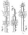
- FIG. 1is an enlarged and exploded front elevational view of a dynamic fixation connecting member assembly according to the invention including first and second elongate members, each with a finned plate, an elongate, core cable fixed to the first member, an elastic bumper, a crimping ring and an outer molded spacer (not shown).
- FIG. 2is a reduced exploded perspective view of the first elongate member and the core cable of FIG. 1 , also showing a cooperating attachment member.
- FIG. 3is an enlarged perspective view of the assembly of FIG. 1 without the bumper, crimping ring and molded spacer.
- FIG. 4is an enlarged front elevational view of the assembly of FIG. 1 , shown assembled.
- FIG. 5is an enlarged front elevational view, similar to FIG. 4 , with portions broken away to show the detail thereof and the molded spacer shown in phantom.
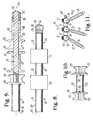
- FIG. 6is an enlarged front elevational view of the assembly of FIG. 1 , shown assembled and with the molded spacer.
- FIG. 7is a reduced front elevational view of the assembly of FIG. 6 shown with three bone screws.
- FIG. 8is an enlarged front elevational view of an alternative embodiment of a dynamic fixation connecting member assembly according to the invention including first and second finned elongate members, an elongate cable core fixed to the first member, an elastic bumper, a crimping ring, a finned sleeve or tube trolley and two outer molded spacers.
- FIG. 9is an enlarged front elevational view of the assembly of FIG. 8 with portions broken away to show the detail thereof.
- FIG. 10is an enlarged front elevational view of the sleeve or tube trolley of FIGS. 8 and 9 .
- FIG. 11is a reduced front elevational view of the assembly of FIG. 8 shown with three bone screws.
- the reference numeral 1generally designates a non-fusion dynamic stabilization longitudinal connecting member assembly according to the present invention.
- the connecting member assembly 1includes first and second elongate segments, generally 4 and 5 , an elastic bumper 6 and a crimping ring 7 .
- the elongate segment 4further includes an inner core extension 8 in the form of a cable, strap or other flexible cord-like extension.
- the inner corecan be used to pretension the device or simply to help limit elongation with distraction.
- the assemblyfurther includes an outer sleeve or spacer 10 .
- the illustrated cable core extension 8includes an elongate body or length 12 and a plug or end portion 13 for inserting and retaining within the segment 4 , utilizing a threaded annular tap 14 that abuts against an annular rigid end surface 15 of the plug 13 as will be described in greater detail below.
- the illustrated core plug 13is integral with the core body 12 . However, it is foreseen that in other embodiments, the plug 13 may be adhered or otherwise fixed to the core body 12 .
- the core cable 8operationally extends along a longitudinal axis A that is also the central longitudinal axis A of the entire assembly 1 when the spacer 10 is molded thereon, connecting the segments 4 and 5 . Again, the core 8 may be pre-tensioned, providing additional stability to the assembly 1 .
- the core 8may be tensioned prior to and/or after molding of the spacer 10 .
- the elongate segments 4 and 5further include respective bone attachment end portions 16 and 18 , respective end plates 20 and 22 having respective integral hooked fin or wing members 24 and 26 .
- Each plate 20 and 22also includes three apertures or through bores 28 and 30 , respectively, spaced substantially equally between the respective fins 24 and 26 .
- the through bores 28 and 30extend substantially parallel to the axis A.
- the central core cable 8is fixed to the plate 20 and extends along the central axis A and between both sets of fins 24 and 26 . As best shown in FIGS. 3 , 4 and 5 , the core 8 also extends through an axial through bore 32 of the segment 5 .
- each of the hooked or cupped fins 24extend axially away from the respective plate 20 , 22 (along the axis A) and also extend radially from near the cable 8 to or substantially near a respective outer peripheral substantially cylindrical surface 36 and 38 of the respective plates 20 and 22 .
- the respective fins 24 and 26include a curved concave or C-shaped hooked or cupped surface 40 and 42 , respectively, such surface facing outwardly away from the axis A and running from the respective plates 20 and 22 to near respective end surfaces 44 and 46 .
- Each of the three fins 24further include threaded inwardly facing surfaces 47 that extend from the plate 20 to the respective end surfaces 44 and are sized and shaped to threadably mate with the threaded annular tap 14 , as will be described in detail below.
- the surfaces 44are near and in substantially uniform spaced relation with the plate 22 and the surfaces 46 are near and in substantially uniform spaced relation with the plate 20 .
- the hooked surfaces 40 and 42provide structure for mechanical cooperation and grabbing attachment with the molded spacer 10 as will be discussed in greater detail below.
- the spacer 10is molded about the hooked fins 24 and 26 , about the core 8 located between the plates 20 and 22 , and through the apertures or bores 28 and 30 of the respective plates 20 and 22 in a manner so as to result in a mechanically connected structure, the elastomeric material completely surrounding the plates 20 and 22 as well as the fins 24 and 26 .
- the elastomeric material of the molded spacer 10may also adhere to fin, core and plate surfaces and not completely surround the plates 20 and 22 .
- An adhesivemay also be added to provide such adherence between the spacer 10 and the plates and fins.
- a coating or sleevemay be placed around the core cable 8 portion located between the plates 20 and 22 prior to molding so that the core cable 8 is spaced from the spacer 10 and thus slidably movable with respect to the spacer 10 .
- the plate 20includes a surface 48 from which the fins 24 extend. As best illustrated in FIG. 5 , formed in the plate surface 48 , at and about the axis A, is a central aperture 50 , sized and shaped for receiving the plug 13 and a portion of the body 12 of the inner core cable 8 . An inner cylindrical threaded section 51 disposed adjacent to the plate surface 48 partially defines the aperture 50 . The threaded section 51 is sized to threadably mate with the threaded annular tap 14 at an outer threaded surface 52 thereof. The threaded annular tap 14 further includes an abutment surface 53 and an opposite or top surface having a drive feature 54 thereon.
- the surfaces forming the aperture 50may also be crimped about the core cable 8 .
- the molded spacer 10will also adhere to the flexible cable 8 , fixing the cable 8 to the spacer 10 that is in turn fixed about the plates 20 and 22 and the fins 24 and 26 of the assembly 1
- the dynamic connecting member assembly 1cooperates with at least a pair of bone anchors (three shown in FIG. 7 ), such as the polyaxial bone screws, generally 55 and cooperating closure structures 57 shown in FIG. 7 , the assembly 1 being captured and fixed in place at the end portions 16 and 18 by cooperation between the bone screws 55 and the closure structures 57 with the spacer 10 being disposed between an adjacent pair of the bone screws 55 .
- bone anchorsthree shown in FIG. 7
- the assembly 1being captured and fixed in place at the end portions 16 and 18 by cooperation between the bone screws 55 and the closure structures 57 with the spacer 10 being disposed between an adjacent pair of the bone screws 55 .
- the connecting member assembly 1may be used with a wide variety of bone anchors already available for cooperation with rigid rods including fixed, monoaxial bone screws, hinged bone screws, polyaxial bone screws, and bone hooks and the like, with or without one or more compression inserts, that may in turn cooperate with a variety of closure structures having threads, flanges, or other structure for fixing the closure structure to the bone anchor, and may include other features, for example, break-off tops and inner set screws as well as associated pressure inserts.
- the portions 16 and 18may in other embodiments of the invention have larger and smaller diameters and other cross-sectional shapes, including, but not limited to oval, square, rectangular and other curved or polygonal shapes and be configured in a non-linear relationship.
- the bone anchors, closure structures and the connecting member assembly 1are then operably incorporated in an overall spinal implant system for correcting degenerative conditions, deformities, injuries, or defects to the spinal column of a patient.
- the illustrated polyaxial bone screws 55each include a shank 60 for insertion into a vertebra (not shown), the shank 60 being pivotally attached to an open receiver or head 61 .
- the shank 60includes a threaded outer surface and may further include a central cannula or through-bore disposed along an axis of rotation of the shank to provide a passage through the shank interior for a length of wire or pin inserted into the vertebra prior to the insertion of the shank 60 , the wire or pin providing a guide for insertion of the shank 60 into the vertebra.
- the receiver 61has a pair of spaced and generally parallel arms that form an open generally U-shaped channel therebetween that is open at distal ends of the arms.
- the armseach include radially inward or interior surfaces that have a discontinuous guide and advancement structure mateable with cooperating structure on the closure structure 57 .
- the guide and advancement structuremay take a variety of forms including a partial helically wound flangeform, a buttress thread, a square thread, a reverse angle thread or other thread like or non-thread like helically wound advancement structure for operably guiding under rotation and advancing the closure structure 57 downward between the receiver 61 arms and having such a nature as to resist splaying of the arms when the closure 57 is advanced into the U-shaped channel.
- a flange form on the illustrated closure 57 and cooperating structure on the arms of the receiver 61is disclosed in Applicant's U.S. Pat. No. 6,726,689, which is incorporated herein by reference.
- the shank 60 and the receiver 61may be attached in a variety of ways.
- a spline capture connectionas described in U.S. Pat. No. 6,716,214, and incorporated by reference herein, is used for the embodiment disclosed herein.
- Polyaxial bone screws with other types of capture connectionsmay also be used according to the invention, including but not limited to, threaded connections, frictional connections utilizing frusto-conical or polyhedral capture structures, integral top or downloadable shanks, and the like.
- polyaxial and other bone screws for use with connecting members of the inventionmay have bone screw shanks that attach directly to the segments 16 and 18 may include compression members or inserts that cooperate with the bone screw shank, receiver and closure structure to secure the connecting member assembly to the bone screw and/or fix the bone screw shank at a desired angle with respect to the bone screw receiver that holds the longitudinal connecting member assembly.
- closure structure 57 of the present inventionis illustrated with the polyaxial bone screw 55 having an open receiver or head 61 , it foreseen that a variety of closure structure may be used in conjunction with any type of medical implant having an open or closed head, including monoaxial bone screws, hinged bone screws, hooks and the like used in spinal surgery.
- the threaded shank 60may be coated, perforated, made porous or otherwise treated.
- the treatmentmay include, but is not limited to a plasma spray coating or other type of coating of a metal or, for example, a calcium phosphate; or a roughening, perforation or indentation in the shank surface, such as by sputtering, sand blasting or acid etching, that allows for bony ingrowth or ongrowth.
- Certain metal coatingsact as a scaffold for bone ingrowth.
- Bio-ceramic calcium phosphate coatingsinclude, but are not limited to: alpha-tri-calcium phosphate and beta-tri-calcium phosphate (Ca 3 (PO 4 ) 2 , tetra-calcium phosphate (Ca 4 P 2 O 9 ), amorphous calcium phosphate and hydroxyapatite (Ca 10 (PO 4 ) 6 (OH) 2 ).
- Coating with hydroxyapatitefor example, is desirable as hydroxyapatite is chemically similar to bone with respect to mineral content and has been identified as being bioactive and thus not only supportive of bone ingrowth, but actively taking part in bone bonding.
- the closure structure 57can be any of a variety of different types of closure structures for use in conjunction with the present invention with suitable mating structure on the interior surface of the upstanding arms the receiver 61 .
- the illustrated closure structure 57is rotatable between the spaced receiver arms, but could be a twist-in or a slide-in closure structure.
- the closure 57includes an outer helically wound guide and advancement structure in the form of a flange form that operably joins with the guide and advancement structure disposed on the interior of the arms of the receiver 61 .
- the illustrated closure structure 57includes a lower or bottom surface that is substantially planar and may include a point and/or a rim protruding therefrom for engaging the portion 16 or 18 outer cylindrical surface.
- the closure structure 57has a top surface with an internal drive feature, that may be, for example, a star-shaped drive aperture sold under the trademark TORX.
- a driving tool(not shown) sized and shaped for engagement with the internal drive feature is used for both rotatable engagement and, if needed, disengagement of the closure 57 from the arms of the receiver 61 .
- the tool engagement structuremay take a variety of forms and may include, but is not limited to, a hex shape or other features or apertures, such as slotted, tri-wing, spanner, two or more apertures of various shapes, and the like.
- closure structure 57may alternatively include a break-off head designed to allow such a head to break from a base of the closure at a preselected torque, for example, 70 to 140 inch pounds.
- a closure structurewould also include a base having an internal drive to be used for closure removal.
- the longitudinal connecting member assembly 1 illustrated in FIGS. 1-7is elongate, with the attachment portion 16 , the plate 20 and the fins 24 being integral and the attachment portion 18 , the plate 22 and the fins 26 being integral.
- the inner core cable 8is fixed to the plate 20 and is slidingly received in the portion 18 .
- the segments 4 and 5are preferably made from metal, metal alloys, such as cobalt chrome, or other suitable materials, including but not limited to stainless steel, titanium and nickel titanium (NiTi, a shape memory alloy also commonly referred to by its trade name, Nitinol).
- the segments 4 and 5may also be made from plastic polymers such as polyetheretherketone (PEEK), ultra-high-molecular weight-polyethylene (UHMWP), polyurethanes and composites.
- the core cable 8 with integral or attached plug 13may also be made from the metals, metal alloys and plastic polymers described herein with respect to the segments 4 and 5 , as well as more flexible materials, such as elastomeric strands or cords made from polyethylene or polyurethane blends integral with or otherwise fixed (such as crimped) to a more rigid, solid plug 13 of the same or different material.
- the elastomeric molded spacer 10may be made of a variety of materials including plastics and composites.
- the illustrated spacer 10is a molded thermoplastic elastomer, for example, polyurethane or a polyurethane blend. However, any suitable polymer material may be used for the spacer 10 and the cable 8 .
- the end portion 16is a substantially solid, smooth uniform cylinder or rod, having a uniform circular cross-section.
- the end portion 18is tubular with inner and outer circular cross-sections, and also having an outer profile that is a smooth uniform cylinder having an outer diameter the same as the outer diameter of the portion 16 ; however, the diameters could be different.
- the core cable 8terminates at an end 66 and the tubular end portion 18 terminates at an end 68 .
- the portions 16 and 18are each sized and shaped to be received in the channel formed between arms of a bone screw receiver 61 with the plates 20 and 22 and the molded spacer 10 disposed between cooperating adjacent bone screws 55 .
- the core cable 8Prior to final assembly, the core cable 8 is typically of a length greater than that shown in the drawing figures so that the core 8 may be grasped by a tool (not shown) near the end 66 and pulled along the axis A in a direction away from the attachment portion 16 in order to place tension on the core cable 8 .
- the spacer 10advantageously cooperates with the plates 20 and 22 , the fins 24 and 26 and the core cable 8 to provide a flexible or dynamic segment that allows for angular (bending and torsion) and linear displacements (compression and distraction) of the assembly 1 .
- the spacer 10further provides a smooth substantially cylindrical surface that protects a patient's body tissue from damage that might otherwise occur with, for example, a spring-like dynamic member or a corded member wherein an outer spacer may be pulled away from a cooperating plate or bone screw surface.
- the over-molded spacer 10prevents soft tissues, including scar tissue, from getting between the end plates 20 and 22 and the polymer of the molded spacer 10 .
- the molded spacer 10is fabricated about the plates 20 and 22 and the fins 24 and 26 , as will be described more fully below, and in the presence of the core cable 8 , with molded plastic flowing about the plates, cable and fins.
- the formed elastomeris substantially cylindrical in outer form with an external substantially cylindrical surface 74 that has the same or substantially similar diameter as the diameter of the outer cylindrical surfaces 36 and 38 of the respective stop or abutment plates 20 and 22 . It is foreseen that in some embodiments, the spacer may be molded to be of square, rectangular or other outer and inner cross-sections including curved or polygonal shapes.
- the portion 16 , portion 18 and even the inner cable 8may also be of other cross-sectional shapes and sizes, including, but not limited to, square, rectangular and other outer and inner cross-sections, including curved or polygonal shapes.
- the spacer 10may further include one or more compression grooves (not shown) formed in the surface 74 .
- a sleeve or other materialmay be placed about the core cable 8 so that the spacer 10 has in internal surface of a slightly greater diameter than an outer diameter of the cable 8 , allowing for axially directed sliding movement of the spacer 10 with respect to the core cable 8 .
- the bumper 6is substantially cylindrical, including an outer surface 78 and an inner surface 79 forming a substantially cylindrical through bore that opens at planar opposed end surfaces 80 and 81 and operatively extends along the axis A.
- the bumper 6further includes a compression groove 82 and can be variable in length.
- the bumper 6is sized and shaped to slidingly receive the core cable 8 through the inner surface 79 .
- the bumper 6is preferably made from an elastomeric material such as polyurethane, that may be equal to the stiffness of the spacer or softer.
- the bumper 6operatively provides axial tension on the core cable 8 , as will be described in greater detail below.
- the crimping ring 7is substantially cylindrical and includes an outer surface 90 and an inner surface 91 forming a substantially cylindrical through bore that opens at opposed planar end surfaces 92 and 93 and operatively extends along the axis A.
- the crimping ring 7is sized and shaped to receive the elongate core cable 8 through the inner surface 91 .
- the crimping ring 7further includes a pair of crimp or compression grooves 96 that are pressable and deformable inwardly toward the axis A upon final tensioning of the core 8 and the spacer 10 during assembly of the assembly 1 .
- the crimping ring 7is preferably made from a stiff, but deformable material, including metals and metal alloys. The ring 7 may also use a set screw to lock it to the cable as opposed to crimping, etc.
- each vertebramay be pre-drilled to minimize stressing the bone.
- each vertebrawill have a guide wire or pin (not shown) inserted therein that is shaped for the bone screw cannula of the bone screw shank 60 and provides a guide for the placement and angle of the shank 60 with respect to the cooperating vertebra.
- a further tap holemay be made and the shank 60 is then driven into the vertebra by rotation of a driving tool (not shown) that engages a driving feature at or near a top of the shank 60 .
- a driving toolnot shown
- the longitudinal connecting member assembly 1may be assembled to provide a pre-tensioned core cable 8 and pre-compressed spacer 10 and bumper 6 prior to implanting the assembly 1 in a patient. This is accomplished by first providing the segment 4 that has the core cable 8 fixed thereto. With particular reference to FIGS. 2 and 5 , to attach the cable 8 to the segment 4 , the end 66 of the cable 8 is inserted into the threaded annular tap 14 at the abutment surface 53 and out the surface having the drive 54 . The cable 8 is threaded through the threaded annular tap 14 until the surface 15 of the plug 13 contacts the abutment surface 53 .
- the threaded annular tap 14is then rotated and driven into the threaded portion 51 defining the aperture 50 utilizing a tool (not shown) engaged with the drive feature 54 until the threaded annular tap 14 is fully disposed within the aperture 50 .
- the cable body 12may initially be longer in the axial direction A than the cable 8 illustrated in the drawing figures to allow for gripping, tensioning and any other manipulation thereof near the end 66 .
- the cable 8is threaded through the segment 5 with the fins 26 of the plate 22 facing the fins 24 of the segment 4 .
- the core cable 8is received in the bore 32 and the segment 5 is moved along the core cable 8 toward the plate 20 .
- the fins 24 and 26are manipulated to be evenly spaced from one another with a desired uniform substantially equal space between the fin ends 46 and the plate 20 and the fin ends 44 and the plate 22 . This is performed in a factory setting with the end portions 16 and 18 held in a jig or other holding mechanism that frictionally engages and holds the sections 16 and 18 , for example, and the spacer 10 is molded about the plates 20 and 22 as well as the fins 24 and 26 as shown in phantom in FIG. 5 .
- the elastomer of the spacer 10flows through the plate through bores 28 and 30 as well as around and about each of the fins 24 and 26 , the resulting molded spacer 10 surrounding all of the surfaces of the plates 20 and 22 as well as all of the surfaces of the fins 24 and 26 .
- a sheath or coatingmay be placed about the core cable 8 so that the spacer 10 material does not contact the core cable 8 .
- the elastomeris allowed to flow about and contact the core cable 8 , that may be pre-tensioned, tensioned after the molding process, or held in a neutral or slackened condition.
- the jig or holding mechanismmay the be released from the portions 16 and 18 after the molding of the spacer 10 is completed.
- the portions 16 and 18may be held in a straight or angled position.
- the bumper 6is loaded onto the core cable 8 by inserting the cable 8 end 66 into the bore defined by the inner surface 79 with the face 80 facing the toward the surface 68 of the portion 18 .
- the bumper 6is moved along the core cable 8 until the surface 80 contacts the surface 68 .
- the crimping ring 7is thereafter loaded onto the cable 8 by inserting the cable 8 end 66 into the bore defined by the inner surface 91 with the face 92 facing the toward the surface 81 of the bumper 6 .
- the crimping ring 7is moved along the core cable 8 until the surface 92 contacts the surface 81 . It is noted that due to the symmetrical nature of the bumper 6 and the crimping ring 7 , these components may be loaded onto the core cable 8 from either side thereof.
- manipulation toolsmay be used to grasp the core cable 8 near the end 66 and at the bone anchor attachment portion 16 , placing tension on the core cable 8 .
- the spacer 10 and/or the bumper 6may be compressed, followed by deforming the crimping ring at the crimp grooves 96 and against the core cable 8 .
- the manipulation toolsare released, the crimping ring 7 , now firmly and fixedly attached to the core cable 8 holds the spacer 10 and/or the bumper 6 in compression and the spacer and/or the bumper places axial tension forces on the core cable 8 , resulting in a dynamic relationship between the core cable 8 and the spacer 10 and/or the bumper 6 .
- the crimping ring 7may be crimped into frictional engagement with the cable 8 while the cable 8 is in a neutral or slack condition. Then, after implantation, body movements may place the cable 8 in tension and the spacer 10 and/or bumper 6 into compression. In certain embodiments according to the invention, the bumper 6 may be omitted.
- the assembly 1is eventually positioned in an open or percutaneous manner in cooperation with the at least two bone screws 55 and shown with three bone screws 55 with the spacer 10 disposed between two adjacent bone screws 55 and the end portions 16 and 18 each within the U-shaped channels of the three bone screws 55 .
- a closure structure 57is then inserted into and advanced between the arms of each of the bone screws 55 .
- the closure structure 57is rotated, using a tool (not shown) engaged with the inner drive until a selected pressure is reached at which point the portion 16 or 18 is urged toward, but not completely seated in the U-shaped channels of the bone screws 55 .
- a selected pressurefor example, about 80 to about 120 inch pounds pressure may be required for fixing the bone screw shank 60 with respect to the receiver 61 at a desired angle of articulation.
- the assembly 1is thus substantially dynamically loaded and oriented relative to the cooperating vertebra, providing relief (e.g., shock absorption) and protected movement with respect to flexion, extension, distraction, compressive, torsion and shear forces placed on the assembly 1 and the connected bone screws 55 .
- the spacer 10 and cooperating core 8 and fins 24 and 26allows the assembly 1 to twist or turn, providing some relief for torsional stresses.
- the spacer 10 in cooperation with the fins 24 and 26limits such torsional movement as well as bending movement, compression and distraction, providing spinal support.
- the core 8further provides protection against sheer and other stresses placed on the assembly 1 .
- disassemblyis accomplished by using the driving tool (not shown) with a driving formation cooperating with the closure structure 57 internal drive to rotate and remove the closure structure 57 from the receiver 61 . Disassembly is then accomplished in reverse order to the procedure described previously herein for assembly.
- the connecting member assembly 1may be removed and replaced with another longitudinal connecting member, such as a solid rod, having the same diameter as the end portions 16 and 18 , utilizing the same receivers 61 and the same or similar closure structures 57 .
- another longitudinal connecting membersuch as a solid rod
- a less rigid, more flexible assemblyfor example, an assembly 1 made without the core 8 or with a spacer 10 made from a more flexible material, or with fewer fins, but with end portions having the same diameter as the portions 16 and 18 , may replace the assembly 1 , also utilizing the same bone screws 55 .
- the reference numeral 101generally designates a second embodiment of a non-fusion dynamic stabilization longitudinal connecting member assembly according to the present invention.
- the connecting member assembly 101includes first and second elongate segments, generally 104 and 105 , an elastic bumper 106 , a crimping ring 107 , and an inner cable core extension 108 , identical or substantially similar to respective segments 4 and 5 , elastic bumper 6 , crimping ring 7 and inner cable 8 of the assembly 1 previously described herein.
- the assembly 101further includes an outer sleeve or tube trolley 109 that is operatively disposed between the segments 104 and 105 .
- the sleeve 109includes fins on either side thereof that cooperate with the fins of the segments 104 and 105 , allowing for a longitudinal connector having more than one dynamic portion, each connected by an over-molded spacer.
- the fins of the segment 104 and one side of the sleeve 109are surrounded by the over-molded portion 110 and the fins of the segment 105 and the opposite side of the sleeve 109 are surrounded by the over-molded portion 111 .
- the over-molded portions or spacers 110 and 111are each identical or substantially similar in form and function to the spacer 10 previously described herein with respect to the assembly 1 .
- the illustrated cable 108extends along a central longitudinal axis AA of the assembly 101 when the spacers 110 and 111 are molded thereon, connecting the segment 104 with the sleeve 109 and the segment 105 with the sleeve 109 , with the cable 108 slidingly received by and extending through the sleeve 109 and the segment 105 .
- the cable 108may be tensioned prior to molding of the spacers 110 and 111 .
- the elongate segments 104 and 105further include respective bone attachment end portions 116 and 118 , respective end plates 120 and 122 having respective integral hooked fin or wing members 124 and 126 .
- the segment 104further includes an end 164 that is opposite an end 166 of the cable 108 .
- the illustrated central cable 108is fixed to the section 104 in a manner identical or substantially similar to the threaded attachment of the cable 8 to the section 4 of the assembly 1 as shown in FIG. 5 .
- the cable 108extends from the plate 120 and along the central axis AA between both sets of fins 124 and 126 and through the sleeve 109 .
- the sleeve or tube trolley 109includes a substantially cylindrical body 170 having an inner lumen or through bore 172 that operatively extends along the axis AA.
- the sleeve 109includes a first end plate 174 and an opposite end plate 175 .
- the end plates 174 and 175have respective integral hooked fin or wing members 178 and 179 .
- each plate 174 and 175also includes three elastomer receiving apertures or through bores 182 and 183 , respectively, spaced substantially equally between the respective fins 178 and 179 .
- the through bores 182 and 183extend substantially parallel to the axis AA.
- the longitudinal connecting member assembly 101may be assembled to provide a neutral cable 8 and neutral spacers 110 and 111 or a pre-tensioned cable 108 and pre-compressed spacers 110 and 111 and bumper 106 prior to implanting the assembly 101 in a patient.
- Pre-tensioningis accomplished by first providing the segment 104 with an inner cable that is longer in the axial direction AA than the cable 108 illustrated in the drawing figures so that the cable 108 may be gripped during compression of the spacers 110 , 111 or bumper 106 and crimping of the ring 107 onto the cable 108 .
- the assembly 101is assembled by threading the sleeve 109 onto the cable 108 , followed by threading the segment 105 onto the cable 108 with the fins 124 of the segment 104 facing the fins 178 of the sleeve 109 and the fins 126 of the segment 105 facing the fins 179 of the sleeve 109 .
- the cable 108is slidingly received in the bores of the sleeve 109 and the segment 105 .
- the facing finsare manipulated to be evenly spaced from one another with a desired uniform space between the fin ends and facing plates. This is performed in a factory setting with the end portions 116 and 118 and sleeve body 170 held in a jig or other holding mechanism that frictionally engages and holds the sections 116 and 118 and the sleeve 109 , for example, and the spacer 110 is molded about the plates 120 and 174 as well as the fins 124 and 178 and the spacer 111 is molded about the plates 122 and 175 as well as the fins 126 and 179 .
- the elastomer of the spacers 110 and 111flows through the bores formed in the plates as well as around and about each of the fins 124 , 126 , 178 and 179 , the resulting molded spacers 110 and 111 surrounding all of the fins surfaces and at least partially and up to fully surrounding the surfaces of the plates 120 , 122 , 174 and 175 .
- a sheath or coatingmay be placed about the cable 108 so that the elastomeric material of the spacers 110 and 111 does not contact the cable 108 .
- the elastomeris allowed to flow about and contact the cable 108 , that may be tensioned before and/or after the molding process.
- the jig or holding mechanismmay then be released from the portions 116 and 118 and the sleeve body 170 after the molding of the spacers 110 and 111 is completed.
- the portions 116 and 118 and the body 170 of the sleeve 109may be held in straight (axial along AA) or angled positions with respect to one another.
- the bumper 106is loaded onto the cable 108 and moved along the cable 108 until the bumper 106 contacts the end portion 118 .
- the crimping ring 107is thereafter loaded onto the core 108 until the ring 107 abuts against the bumper 106 .
- Manipulation tools(not shown) are then used to grasp the cable 108 near the end 166 and at the bone anchor attachment portion 116 , placing tension on the cable 108 , if desired.
- the spacers 110 and 111 and/or the bumper 106may be compressed, followed by deforming the crimping ring at the crimp grooves thereof against the cable 108 as previously described herein with respect to the crimp ring 7 and cable 8 of the assembly 1 .
- the assembly 101is eventually positioned in an open or percutaneous manner in cooperation with three bone screws 55 with the spacer 110 disposed between two adjacent bone screws 55 and the spacer 111 disposed between two adjacent bone screws 55 with the end portions 116 and 118 , and the sleeve body 170 each within the U-shaped channels of one of the three bone screws 55 .
- a closure structure 57is then inserted into and advanced between the arms of each of the bone screws 55 .
- the closure structure 57is rotated, using a tool (not shown) engaged with the inner drive until a selected pressure is reached at which point the portion 16 or 18 is urged toward, but not completely seated in the U-shaped channels of the bone screws 55 .
- a selected pressureis reached at which point the portion 16 or 18 is urged toward, but not completely seated in the U-shaped channels of the bone screws 55 .
- about 80 to about 120 inch pounds pressuremay be required for fixing the bone screw shank 60 with respect to the receiver 61 at a desired angle of articulation.
- the assembly 101is thus substantially dynamically loaded and oriented relative to the cooperating vertebra, providing relief (e.g., shock absorption) and protected movement with respect to flexion, extension, distraction, compressive, torsion and shear forces placed on the assembly 101 and the connected bone screws 55 .
- the spacers 110 and 111 and cooperating cable 108 and fins( 124 and 178 ; and 126 and 179 ) allow the assembly 101 to twist or turn, providing some relief for torsional stresses.
- the spacers 110 and 111 and cooperating over-molded finshowever limit such torsional movement as well as bending movement, compression and distraction, providing spinal support.
- the cable 108further provides protection against sheer stresses placed on the assembly 101 .
- disassemblyis accomplished by using the driving tool (not shown) with a driving formation cooperating with the closure structure 57 internal drive to rotate and remove the closure structure 57 from the receiver 61 . Disassembly is then accomplished in reverse order to the procedure described previously herein for assembly.
Landscapes
- Health & Medical Sciences (AREA)
- Orthopedic Medicine & Surgery (AREA)
- Life Sciences & Earth Sciences (AREA)
- Neurology (AREA)
- Surgery (AREA)
- Heart & Thoracic Surgery (AREA)
- Engineering & Computer Science (AREA)
- Biomedical Technology (AREA)
- Nuclear Medicine, Radiotherapy & Molecular Imaging (AREA)
- Medical Informatics (AREA)
- Molecular Biology (AREA)
- Animal Behavior & Ethology (AREA)
- General Health & Medical Sciences (AREA)
- Public Health (AREA)
- Veterinary Medicine (AREA)
- Surgical Instruments (AREA)
Abstract
Description
This application claims the benefit of U.S. Provisional Patent Application Ser. No. 61/000,955, filed Oct. 30, 2007 and also the benefit of U.S. Provisional Patent Application Ser. No. 60/999,965, filed Oct. 23, 2007, both of which are incorporated by reference herein.
The present invention is directed to dynamic fixation assemblies for use in bone surgery, particularly spinal surgery, and in particular to longitudinal connecting members and cooperating bone anchors or fasteners for such assemblies, the connecting members being attached to at least two bone anchors.
Historically, it has been common to fuse adjacent vertebrae that are placed in fixed relation by the installation therealong of bone screws or other bone anchors and cooperating longitudinal connecting members or other elongate members. Fusion results in the permanent immobilization of one or more of the intervertebral joints. Because the anchoring of bone screws, hooks and other types of anchors directly to a vertebra can result in significant forces being placed on the vertebra, and such forces may ultimately result in the loosening of the bone screw or other anchor from the vertebra, fusion allows for the growth and development of a bone counterpart to the longitudinal connecting member that can maintain the spine in the desired position even if the implants ultimately fail or are removed. Because fusion has been a desired component of spinal stabilization procedures, longitudinal connecting members have been designed that are of a material, size and shape to largely resist flexure, extension, torsion, distraction and compression, and thus substantially immobilize the portion of the spine that is to be fused. Thus, longitudinal connecting members are typically uniform along an entire length thereof, and usually made from a single or integral piece of material having a uniform diameter or width of a size to provide substantially rigid support in all planes.
Fusion, however, has some undesirable side effects. One apparent side effect is the immobilization of a portion of the spine. Furthermore, although fusion may result in a strengthened portion of the spine, it also has been linked to more rapid degeneration and even hyper-mobility and collapse of spinal motion segments that are adjacent to the portion of the spine being fused, reducing or eliminating the ability of such spinal joints to move in a more normal relation to one another. In certain instances, fusion has also failed to provide pain relief.
An alternative to fusion and the use of more rigid longitudinal connecting members or other rigid structure has been a “soft” or “dynamic” stabilization approach in which a flexible loop-, S-, C- or U-shaped member or a coil-like and/or a spring-like member is utilized as an elastic longitudinal connecting member fixed between a pair of pedicle screws in an attempt to create, as much as possible, a normal loading pattern between the vertebrae in flexion, extension, distraction, compression, side bending and torsion. Problems may arise with such devices, however, including tissue scarring, lack of adequate spinal support or being undesirably large or bulky when sized to provide adequate support, and lack of fatigue strength or endurance limit. Fatigue strength has been defined as the repeated loading and unloading of a specific stress on a material structure until it fails. Fatigue strength can be tensile or distraction, compression, shear, torsion, bending, or a combination of these.
Another type of soft or dynamic system known in the art includes bone anchors connected by flexible cords or strands, typically made from a plastic material. Such a cord or strand may be threaded through cannulated spacers that are disposed between adjacent bone anchors when such a cord or strand is implanted, tensioned and attached to the bone anchors. The spacers typically span the distance between bone anchors, providing limits on the bending movement of the cord or strand and thus strengthening and supporting the overall system. Such cord or strand-type systems require specialized bone anchors and tooling for tensioning and holding the cord or strand in the bone anchors. Although flexible, the cords or strands utilized in such systems do not allow for elastic distraction of the system once implanted because the cord or strand must be stretched or pulled to maximum tension in order to provide a stable, supportive system. Also, as currently designed, these systems do not provide any significant torsional resistance. Furthermore, such systems allow the possibility for at least some partial pulling away from or gapping between the adjacent bone screw heads and the cannulated spacers, providing space for the growth of soft tissue and scarring that may result in pinching and resultant pain to the patient as well as altered bio-mechanics for the implants.
The complex dynamic conditions associated with spinal movement therefore provide quite a challenge for the design of elongate elastic longitudinal connecting members that exhibit an adequate fatigue strength to provide stabilization and protected motion of the spine, without fusion, and allow for some natural movement of the portion of the spine being reinforced and supported by the elongate elastic or flexible connecting member. A further challenge are situations in which a portion or length of the spine requires a more rigid stabilization, possibly including fusion, while another portion or length may be better supported by a more dynamic system that allows for protective movement.
Longitudinal connecting member assemblies according to the invention for use between at least two bone anchors provide dynamic, protected motion of the spine and may be extended to provide additional dynamic sections or more rigid support along an adjacent length of the spine, with fusion, if desired. A longitudinal connecting member assembly according to the invention includes first and second elongate segments, each segment having an abutment plate with a plurality of integral fins extending axially from the abutment plate. The fins face one-another and are evenly spaced from one another and are also evenly spaced from the opposing plate. The first connecting member further includes an elongate central inner core extension in the form of a flexible cable or cord that extends axially between the fins and also through the second connecting member. The assembly further includes an elastic molded outer spacer or elastic sleeve substantially or completely disposed about the fins and substantially or completely surrounding each of the plates. The fins may be cupped or hooked to further grab and hold the elastomer. The assembly may further include an optional elastic end bumper that places a distractive force on the elongate inner core. The cooperation between the cupped fins and the elastomeric spacer that may be over-molded around the abutment plates prevents or eliminates gapping or pulling away of the plate from the elastic polymer of the spacer so that soft tissues and body fluids cannot get into such a gap or space, especially when compression is applied on one side of the spacer and resultant distraction on the opposite side, such as when a bending moment is applied to the screws.
An object of the invention is to provide dynamic medical implant stabilization assemblies having longitudinal connecting members that include a flexible portion that allows for bending, torsion, compression and distraction of the assembly. Another object of the invention is to provide such a flexible portion that is molded about cooperating rigid portions such that the flexible portion does not pull away or otherwise separate from the rigid portion in response to body movement or other forces. A further object of the invention is to provide dynamic medical implant longitudinal connecting members that may be utilized with a variety of bone screws, hooks and other bone anchors. Another object of the invention is to provide a more rigid or solid connecting member portion or segment, if desired, such as a solid rod portion integral with or connected to the flexible portion. Additionally, it is an object of the invention to provide a lightweight, reduced volume, low profile assembly including at least two bone anchors and a longitudinal connecting member therebetween. Furthermore, it is an object of the invention to provide apparatus and methods that are easy to use and especially adapted for the intended use thereof and wherein the apparatus are comparatively inexpensive to make and suitable for use.
Other objects and advantages of this invention will become apparent from the following description taken in conjunction with the accompanying drawings wherein are set forth, by way of illustration and example, certain embodiments of this invention.
The drawings constitute a part of this specification and include exemplary embodiments of the present invention and illustrate various objects and features thereof.
As required, detailed embodiments of the present invention are disclosed herein; however, it is to be understood that the disclosed embodiments are merely exemplary of the invention, which may be embodied in various forms. Therefore, specific structural and functional details disclosed herein are not to be interpreted as limiting, but merely as a basis for the claims and as a representative basis for teaching one skilled in the art to variously employ the present invention in virtually any appropriately detailed structure. It is also noted that any reference to the words top, bottom, up and down, and the like, in this application refers to the alignment shown in the various drawings, as well as the normal connotations applied to such devices, and is not intended to restrict positioning of the connecting member assemblies of the application and cooperating bone anchors in actual use.
With reference toFIGS. 1-7 , the reference numeral1 generally designates a non-fusion dynamic stabilization longitudinal connecting member assembly according to the present invention. The connecting member assembly1 includes first and second elongate segments, generally4 and5, an elastic bumper6 and acrimping ring 7. Theelongate segment 4 further includes aninner core extension 8 in the form of a cable, strap or other flexible cord-like extension. The inner core can be used to pretension the device or simply to help limit elongation with distraction. The assembly further includes an outer sleeve orspacer 10. The illustratedcable core extension 8 includes an elongate body orlength 12 and a plug orend portion 13 for inserting and retaining within thesegment 4, utilizing a threadedannular tap 14 that abuts against an annularrigid end surface 15 of theplug 13 as will be described in greater detail below. The illustratedcore plug 13 is integral with thecore body 12. However, it is foreseen that in other embodiments, theplug 13 may be adhered or otherwise fixed to thecore body 12. Thecore cable 8 operationally extends along a longitudinal axis A that is also the central longitudinal axis A of the entire assembly1 when thespacer 10 is molded thereon, connecting thesegments 4 and5. Again, thecore 8 may be pre-tensioned, providing additional stability to the assembly1. Thecore 8 may be tensioned prior to and/or after molding of thespacer 10.
With particular reference toFIGS. 1-5 theelongate segments 4 and5 further include respective boneattachment end portions respective end plates wing members fins respective plates fins plate bores respective fins central core cable 8 is fixed to theplate 20 and extends along the central axis A and between both sets offins FIGS. 3 ,4 and5, thecore 8 also extends through an axial throughbore 32 of the segment5.
As best shown inFIGS. 1-4 , each of the hooked orcupped fins 24, as well as the hooked orcupped fins 26, extend axially away from therespective plate 20,22 (along the axis A) and also extend radially from near thecable 8 to or substantially near a respective outer peripheral substantiallycylindrical surface respective plates peripheral surfaces respective fins cupped surface respective plates fins 24 further include threaded inwardly facingsurfaces 47 that extend from theplate 20 to the respective end surfaces44 and are sized and shaped to threadably mate with the threadedannular tap 14, as will be described in detail below. When thesegments 4 and5 are assembled and set in place by the moldedspacer 10, thesurfaces 44 are near and in substantially uniform spaced relation with theplate 22 and thesurfaces 46 are near and in substantially uniform spaced relation with theplate 20. The hooked surfaces40 and42 provide structure for mechanical cooperation and grabbing attachment with the moldedspacer 10 as will be discussed in greater detail below. Also, as will be described in greater detail below, thespacer 10 is molded about the hookedfins core 8 located between theplates respective plates plates fins plates spacer 10 may also adhere to fin, core and plate surfaces and not completely surround theplates spacer 10 and the plates and fins. Alternatively, in certain embodiments a coating or sleeve may be placed around thecore cable 8 portion located between theplates core cable 8 is spaced from thespacer 10 and thus slidably movable with respect to thespacer 10.
Theplate 20 includes asurface 48 from which thefins 24 extend. As best illustrated inFIG. 5 , formed in theplate surface 48, at and about the axis A, is acentral aperture 50, sized and shaped for receiving theplug 13 and a portion of thebody 12 of theinner core cable 8. An inner cylindrical threadedsection 51 disposed adjacent to theplate surface 48 partially defines theaperture 50. The threadedsection 51 is sized to threadably mate with the threadedannular tap 14 at an outer threadedsurface 52 thereof. The threadedannular tap 14 further includes anabutment surface 53 and an opposite or top surface having adrive feature 54 thereon. After insertion of thecore plug 13 and the threadedannular tap 14 into theaperture 50, the surfaces forming theaperture 50 may also be crimped about thecore cable 8. In some embodiments of the invention, the moldedspacer 10 will also adhere to theflexible cable 8, fixing thecable 8 to thespacer 10 that is in turn fixed about theplates fins
The dynamic connecting member assembly1 cooperates with at least a pair of bone anchors (three shown inFIG. 7 ), such as the polyaxial bone screws, generally55 and cooperatingclosure structures 57 shown inFIG. 7 , the assembly1 being captured and fixed in place at theend portions closure structures 57 with thespacer 10 being disposed between an adjacent pair of the bone screws55.
Because theillustrated end portions portions
The illustrated polyaxial bone screws55 each include ashank 60 for insertion into a vertebra (not shown), theshank 60 being pivotally attached to an open receiver or head61. Theshank 60 includes a threaded outer surface and may further include a central cannula or through-bore disposed along an axis of rotation of the shank to provide a passage through the shank interior for a length of wire or pin inserted into the vertebra prior to the insertion of theshank 60, the wire or pin providing a guide for insertion of theshank 60 into the vertebra. The receiver61 has a pair of spaced and generally parallel arms that form an open generally U-shaped channel therebetween that is open at distal ends of the arms. The arms each include radially inward or interior surfaces that have a discontinuous guide and advancement structure mateable with cooperating structure on theclosure structure 57. The guide and advancement structure may take a variety of forms including a partial helically wound flangeform, a buttress thread, a square thread, a reverse angle thread or other thread like or non-thread like helically wound advancement structure for operably guiding under rotation and advancing theclosure structure 57 downward between the receiver61 arms and having such a nature as to resist splaying of the arms when theclosure 57 is advanced into the U-shaped channel. For example, a flange form on the illustratedclosure 57 and cooperating structure on the arms of the receiver61 is disclosed in Applicant's U.S. Pat. No. 6,726,689, which is incorporated herein by reference.
Theshank 60 and the receiver61 may be attached in a variety of ways. For example, a spline capture connection as described in U.S. Pat. No. 6,716,214, and incorporated by reference herein, is used for the embodiment disclosed herein. Polyaxial bone screws with other types of capture connections may also be used according to the invention, including but not limited to, threaded connections, frictional connections utilizing frusto-conical or polyhedral capture structures, integral top or downloadable shanks, and the like. Also, as indicated above, polyaxial and other bone screws for use with connecting members of the invention may have bone screw shanks that attach directly to thesegments closure structure 57 of the present invention is illustrated with thepolyaxial bone screw 55 having an open receiver or head61, it foreseen that a variety of closure structure may be used in conjunction with any type of medical implant having an open or closed head, including monoaxial bone screws, hinged bone screws, hooks and the like used in spinal surgery.
To provide a biologically active interface with the bone, the threadedshank 60 may be coated, perforated, made porous or otherwise treated. The treatment may include, but is not limited to a plasma spray coating or other type of coating of a metal or, for example, a calcium phosphate; or a roughening, perforation or indentation in the shank surface, such as by sputtering, sand blasting or acid etching, that allows for bony ingrowth or ongrowth. Certain metal coatings act as a scaffold for bone ingrowth. Bio-ceramic calcium phosphate coatings include, but are not limited to: alpha-tri-calcium phosphate and beta-tri-calcium phosphate (Ca3(PO4)2, tetra-calcium phosphate (Ca4P2O9), amorphous calcium phosphate and hydroxyapatite (Ca10(PO4)6(OH)2). Coating with hydroxyapatite, for example, is desirable as hydroxyapatite is chemically similar to bone with respect to mineral content and has been identified as being bioactive and thus not only supportive of bone ingrowth, but actively taking part in bone bonding.
Theclosure structure 57 can be any of a variety of different types of closure structures for use in conjunction with the present invention with suitable mating structure on the interior surface of the upstanding arms the receiver61. The illustratedclosure structure 57 is rotatable between the spaced receiver arms, but could be a twist-in or a slide-in closure structure. Theclosure 57 includes an outer helically wound guide and advancement structure in the form of a flange form that operably joins with the guide and advancement structure disposed on the interior of the arms of the receiver61. The illustratedclosure structure 57 includes a lower or bottom surface that is substantially planar and may include a point and/or a rim protruding therefrom for engaging theportion closure structure 57 has a top surface with an internal drive feature, that may be, for example, a star-shaped drive aperture sold under the trademark TORX. A driving tool (not shown) sized and shaped for engagement with the internal drive feature is used for both rotatable engagement and, if needed, disengagement of theclosure 57 from the arms of the receiver61. The tool engagement structure may take a variety of forms and may include, but is not limited to, a hex shape or other features or apertures, such as slotted, tri-wing, spanner, two or more apertures of various shapes, and the like. It is also foreseen that theclosure structure 57 may alternatively include a break-off head designed to allow such a head to break from a base of the closure at a preselected torque, for example, 70 to 140 inch pounds. Such a closure structure would also include a base having an internal drive to be used for closure removal.
The longitudinal connecting member assembly1 illustrated inFIGS. 1-7 is elongate, with theattachment portion 16, theplate 20 and thefins 24 being integral and theattachment portion 18, theplate 22 and thefins 26 being integral. Theinner core cable 8 is fixed to theplate 20 and is slidingly received in theportion 18. Thesegments 4 and5 are preferably made from metal, metal alloys, such as cobalt chrome, or other suitable materials, including but not limited to stainless steel, titanium and nickel titanium (NiTi, a shape memory alloy also commonly referred to by its trade name, Nitinol). Thesegments 4 and5 may also be made from plastic polymers such as polyetheretherketone (PEEK), ultra-high-molecular weight-polyethylene (UHMWP), polyurethanes and composites. Thecore cable 8 with integral or attachedplug 13 may also be made from the metals, metal alloys and plastic polymers described herein with respect to thesegments 4 and5, as well as more flexible materials, such as elastomeric strands or cords made from polyethylene or polyurethane blends integral with or otherwise fixed (such as crimped) to a more rigid,solid plug 13 of the same or different material. The elastomeric moldedspacer 10 may be made of a variety of materials including plastics and composites. The illustratedspacer 10 is a molded thermoplastic elastomer, for example, polyurethane or a polyurethane blend. However, any suitable polymer material may be used for thespacer 10 and thecable 8.
Specifically, in the illustrated embodiment, theend portion 16 is a substantially solid, smooth uniform cylinder or rod, having a uniform circular cross-section. Theend portion 18 is tubular with inner and outer circular cross-sections, and also having an outer profile that is a smooth uniform cylinder having an outer diameter the same as the outer diameter of theportion 16; however, the diameters could be different. Thecore cable 8 terminates at anend 66 and thetubular end portion 18 terminates at anend 68. Theportions plates spacer 10 disposed between cooperating adjacent bone screws55. Prior to final assembly, thecore cable 8 is typically of a length greater than that shown in the drawing figures so that thecore 8 may be grasped by a tool (not shown) near theend 66 and pulled along the axis A in a direction away from theattachment portion 16 in order to place tension on thecore cable 8.
Thespacer 10 advantageously cooperates with theplates fins core cable 8 to provide a flexible or dynamic segment that allows for angular (bending and torsion) and linear displacements (compression and distraction) of the assembly1. Thespacer 10 further provides a smooth substantially cylindrical surface that protects a patient's body tissue from damage that might otherwise occur with, for example, a spring-like dynamic member or a corded member wherein an outer spacer may be pulled away from a cooperating plate or bone screw surface. Thus, theover-molded spacer 10 prevents soft tissues, including scar tissue, from getting between theend plates spacer 10.
The moldedspacer 10 is fabricated about theplates fins core cable 8, with molded plastic flowing about the plates, cable and fins. The formed elastomer is substantially cylindrical in outer form with an external substantiallycylindrical surface 74 that has the same or substantially similar diameter as the diameter of the outercylindrical surfaces abutment plates portion 16,portion 18 and even theinner cable 8 may also be of other cross-sectional shapes and sizes, including, but not limited to, square, rectangular and other outer and inner cross-sections, including curved or polygonal shapes. Thespacer 10 may further include one or more compression grooves (not shown) formed in thesurface 74. During the molding process a sleeve or other material (not shown) may be placed about thecore cable 8 so that thespacer 10 has in internal surface of a slightly greater diameter than an outer diameter of thecable 8, allowing for axially directed sliding movement of thespacer 10 with respect to thecore cable 8.
With reference toFIGS. 1 ,4,5 and6, the bumper6 is substantially cylindrical, including anouter surface 78 and aninner surface 79 forming a substantially cylindrical through bore that opens at planar opposed end surfaces80 and81 and operatively extends along the axis A. The bumper6 further includes acompression groove 82 and can be variable in length. The bumper6 is sized and shaped to slidingly receive thecore cable 8 through theinner surface 79. The bumper6 is preferably made from an elastomeric material such as polyurethane, that may be equal to the stiffness of the spacer or softer. The bumper6 operatively provides axial tension on thecore cable 8, as will be described in greater detail below.
Also with particular reference toFIGS. 1 ,4,5 and6, the crimpingring 7 is substantially cylindrical and includes anouter surface 90 and aninner surface 91 forming a substantially cylindrical through bore that opens at opposed planar end surfaces92 and93 and operatively extends along the axis A. The crimpingring 7 is sized and shaped to receive theelongate core cable 8 through theinner surface 91. The crimpingring 7 further includes a pair of crimp orcompression grooves 96 that are pressable and deformable inwardly toward the axis A upon final tensioning of thecore 8 and thespacer 10 during assembly of the assembly1. The crimpingring 7 is preferably made from a stiff, but deformable material, including metals and metal alloys. Thering 7 may also use a set screw to lock it to the cable as opposed to crimping, etc.
In use, at least twobone screws 55 are implanted into vertebrae for use with the longitudinal connecting member assembly1. Each vertebra may be pre-drilled to minimize stressing the bone. Furthermore, when a cannulated bone screw shank is utilized, each vertebra will have a guide wire or pin (not shown) inserted therein that is shaped for the bone screw cannula of thebone screw shank 60 and provides a guide for the placement and angle of theshank 60 with respect to the cooperating vertebra. A further tap hole may be made and theshank 60 is then driven into the vertebra by rotation of a driving tool (not shown) that engages a driving feature at or near a top of theshank 60. It is foreseen that thescrews 55 and the longitudinal connecting member1 can be inserted in a percutaneous or minimally invasive surgical manner.
The longitudinal connecting member assembly1 may be assembled to provide apre-tensioned core cable 8 andpre-compressed spacer 10 and bumper6 prior to implanting the assembly1 in a patient. This is accomplished by first providing thesegment 4 that has thecore cable 8 fixed thereto. With particular reference toFIGS. 2 and 5 , to attach thecable 8 to thesegment 4, theend 66 of thecable 8 is inserted into the threadedannular tap 14 at theabutment surface 53 and out the surface having thedrive 54. Thecable 8 is threaded through the threadedannular tap 14 until thesurface 15 of theplug 13 contacts theabutment surface 53. The threadedannular tap 14 is then rotated and driven into the threadedportion 51 defining theaperture 50 utilizing a tool (not shown) engaged with thedrive feature 54 until the threadedannular tap 14 is fully disposed within theaperture 50. Thecable body 12 may initially be longer in the axial direction A than thecable 8 illustrated in the drawing figures to allow for gripping, tensioning and any other manipulation thereof near theend 66. Thecable 8 is threaded through the segment5 with thefins 26 of theplate 22 facing thefins 24 of thesegment 4. Thecore cable 8 is received in thebore 32 and the segment5 is moved along thecore cable 8 toward theplate 20. Thefins plate 20 and the fin ends44 and theplate 22. This is performed in a factory setting with theend portions sections spacer 10 is molded about theplates fins FIG. 5 . The elastomer of thespacer 10 flows through the plate throughbores fins spacer 10 surrounding all of the surfaces of theplates fins core cable 8 so that thespacer 10 material does not contact thecore cable 8. However, in other embodiments of the invention, the elastomer is allowed to flow about and contact thecore cable 8, that may be pre-tensioned, tensioned after the molding process, or held in a neutral or slackened condition. The jig or holding mechanism may the be released from theportions spacer 10 is completed. Theportions
Either before or after molding, the bumper6 is loaded onto thecore cable 8 by inserting thecable 8end 66 into the bore defined by theinner surface 79 with theface 80 facing the toward thesurface 68 of theportion 18. The bumper6 is moved along thecore cable 8 until thesurface 80 contacts thesurface 68. The crimpingring 7 is thereafter loaded onto thecable 8 by inserting thecable 8end 66 into the bore defined by theinner surface 91 with theface 92 facing the toward thesurface 81 of the bumper6. The crimpingring 7 is moved along thecore cable 8 until thesurface 92 contacts thesurface 81. It is noted that due to the symmetrical nature of the bumper6 and the crimpingring 7, these components may be loaded onto thecore cable 8 from either side thereof.
After the crimpingring 7 is loaded onto thecore cable 8, manipulation tools (not shown) may be used to grasp thecore cable 8 near theend 66 and at the boneanchor attachment portion 16, placing tension on thecore cable 8. Furthermore, thespacer 10 and/or the bumper6 may be compressed, followed by deforming the crimping ring at thecrimp grooves 96 and against thecore cable 8. When the manipulation tools are released, the crimpingring 7, now firmly and fixedly attached to thecore cable 8 holds thespacer 10 and/or the bumper6 in compression and the spacer and/or the bumper places axial tension forces on thecore cable 8, resulting in a dynamic relationship between thecore cable 8 and thespacer 10 and/or the bumper6. Alternatively, the crimpingring 7 may be crimped into frictional engagement with thecable 8 while thecable 8 is in a neutral or slack condition. Then, after implantation, body movements may place thecable 8 in tension and thespacer 10 and/or bumper6 into compression. In certain embodiments according to the invention, the bumper6 may be omitted.
With reference toFIG. 7 , the assembly1 is eventually positioned in an open or percutaneous manner in cooperation with the at least twobone screws 55 and shown with threebone screws 55 with thespacer 10 disposed between two adjacent bone screws55 and theend portions closure structure 57 is then inserted into and advanced between the arms of each of the bone screws55. Theclosure structure 57 is rotated, using a tool (not shown) engaged with the inner drive until a selected pressure is reached at which point theportion bone screw shank 60 with respect to the receiver61 at a desired angle of articulation.
The assembly1 is thus substantially dynamically loaded and oriented relative to the cooperating vertebra, providing relief (e.g., shock absorption) and protected movement with respect to flexion, extension, distraction, compressive, torsion and shear forces placed on the assembly1 and the connected bone screws55. Thespacer 10 and cooperatingcore 8 andfins spacer 10 in cooperation with thefins core 8 further provides protection against sheer and other stresses placed on the assembly1.
If removal of the assembly1 from any of thebone screw assemblies 55 is necessary, or if it is desired to release the assembly1 at a particular location, disassembly is accomplished by using the driving tool (not shown) with a driving formation cooperating with theclosure structure 57 internal drive to rotate and remove theclosure structure 57 from the receiver61. Disassembly is then accomplished in reverse order to the procedure described previously herein for assembly.
Eventually, if the spine requires more rigid support, the connecting member assembly1 according to the invention may be removed and replaced with another longitudinal connecting member, such as a solid rod, having the same diameter as theend portions similar closure structures 57. Alternatively, if less support is eventually required, a less rigid, more flexible assembly, for example, an assembly1 made without thecore 8 or with aspacer 10 made from a more flexible material, or with fewer fins, but with end portions having the same diameter as theportions
With reference toFIGS. 8-11 , thereference numeral 101 generally designates a second embodiment of a non-fusion dynamic stabilization longitudinal connecting member assembly according to the present invention. The connectingmember assembly 101 includes first and second elongate segments, generally104 and105, anelastic bumper 106, a crimpingring 107, and an innercable core extension 108, identical or substantially similar torespective segments 4 and5, elastic bumper6, crimpingring 7 andinner cable 8 of the assembly1 previously described herein. Theassembly 101 further includes an outer sleeve ortube trolley 109 that is operatively disposed between thesegments 104 and105. As will be described in greater detail below, thesleeve 109 includes fins on either side thereof that cooperate with the fins of thesegments 104 and105, allowing for a longitudinal connector having more than one dynamic portion, each connected by an over-molded spacer. In theembodiment 101, the fins of the segment104 and one side of thesleeve 109 are surrounded by theover-molded portion 110 and the fins of thesegment 105 and the opposite side of thesleeve 109 are surrounded by the over-molded portion111. The over-molded portions orspacers 110 and111 are each identical or substantially similar in form and function to thespacer 10 previously described herein with respect to the assembly1.
The illustratedcable 108 extends along a central longitudinal axis AA of theassembly 101 when thespacers 110 and111 are molded thereon, connecting the segment104 with thesleeve 109 and thesegment 105 with thesleeve 109, with thecable 108 slidingly received by and extending through thesleeve 109 and thesegment 105. Thecable 108 may be tensioned prior to molding of thespacers 110 and111.
With particular reference toFIG. 9 , similar to thesegments 4 and5, theelongate segments 104 and105 further include respective boneattachment end portions respective end plates wing members fins respective plates fins end 164 that is opposite anend 166 of thecable 108. The illustratedcentral cable 108 is fixed to the section104 in a manner identical or substantially similar to the threaded attachment of thecable 8 to thesection 4 of the assembly1 as shown inFIG. 5 . Thecable 108 extends from theplate 120 and along the central axis AA between both sets offins sleeve 109.
With particular reference toFIGS. 9 and 10 , the sleeve ortube trolley 109 includes a substantiallycylindrical body 170 having an inner lumen or throughbore 172 that operatively extends along the axis AA. Thesleeve 109 includes afirst end plate 174 and anopposite end plate 175. Theend plates wing members fins respective plates fins fins fins central cable 108 extends along the central axis AA between both sets offins bore 172. Eachplate bores respective fins
With reference toFIG. 11 , in use, at least threebone screws 55 are implanted into vertebrae for use with the longitudinal connectingmember assembly 101 in the same or similar manner as previously discussed herein with respect to the assembly1. With reference toFIG. 9 , the longitudinal connectingmember assembly 101 may be assembled to provide aneutral cable 8 andneutral spacers 110 and111 or apre-tensioned cable 108 andpre-compressed spacers 110 and111 andbumper 106 prior to implanting theassembly 101 in a patient. Pre-tensioning is accomplished by first providing the segment104 with an inner cable that is longer in the axial direction AA than thecable 108 illustrated in the drawing figures so that thecable 108 may be gripped during compression of thespacers 110,111 orbumper 106 and crimping of thering 107 onto thecable 108. In all installations, theassembly 101 is assembled by threading thesleeve 109 onto thecable 108, followed by threading thesegment 105 onto thecable 108 with thefins 124 of the segment104 facing thefins 178 of thesleeve 109 and thefins 126 of thesegment 105 facing thefins 179 of thesleeve 109. Thecable 108 is slidingly received in the bores of thesleeve 109 and thesegment 105. The facing fins are manipulated to be evenly spaced from one another with a desired uniform space between the fin ends and facing plates. This is performed in a factory setting with theend portions sleeve body 170 held in a jig or other holding mechanism that frictionally engages and holds thesections sleeve 109, for example, and thespacer 110 is molded about theplates fins plates fins spacers 110 and111 flows through the bores formed in the plates as well as around and about each of thefins spacers 110 and111 surrounding all of the fins surfaces and at least partially and up to fully surrounding the surfaces of theplates cable 108 so that the elastomeric material of thespacers 110 and111 does not contact thecable 108. However, in other embodiments of the invention, the elastomer is allowed to flow about and contact thecable 108, that may be tensioned before and/or after the molding process. The jig or holding mechanism may then be released from theportions sleeve body 170 after the molding of thespacers 110 and111 is completed. Theportions body 170 of thesleeve 109 may be held in straight (axial along AA) or angled positions with respect to one another.
Either before or after molding, thebumper 106 is loaded onto thecable 108 and moved along thecable 108 until thebumper 106 contacts theend portion 118. The crimpingring 107 is thereafter loaded onto thecore 108 until thering 107 abuts against thebumper 106. Manipulation tools (not shown) are then used to grasp thecable 108 near theend 166 and at the boneanchor attachment portion 116, placing tension on thecable 108, if desired. Furthermore, thespacers 110 and111 and/or thebumper 106 may be compressed, followed by deforming the crimping ring at the crimp grooves thereof against thecable 108 as previously described herein with respect to thecrimp ring 7 andcable 8 of the assembly1.
With reference toFIG. 11 , theassembly 101 is eventually positioned in an open or percutaneous manner in cooperation with threebone screws 55 with thespacer 110 disposed between two adjacent bone screws55 and the spacer111 disposed between two adjacent bone screws55 with theend portions sleeve body 170 each within the U-shaped channels of one of the three bone screws55. Aclosure structure 57 is then inserted into and advanced between the arms of each of the bone screws55. Theclosure structure 57 is rotated, using a tool (not shown) engaged with the inner drive until a selected pressure is reached at which point theportion bone screw shank 60 with respect to the receiver61 at a desired angle of articulation.
Theassembly 101 is thus substantially dynamically loaded and oriented relative to the cooperating vertebra, providing relief (e.g., shock absorption) and protected movement with respect to flexion, extension, distraction, compressive, torsion and shear forces placed on theassembly 101 and the connected bone screws55. Thespacers 110 and111 and cooperatingcable 108 and fins (124 and178; and126 and179) allow theassembly 101 to twist or turn, providing some relief for torsional stresses. Thespacers 110 and111 and cooperating over-molded fins, however limit such torsional movement as well as bending movement, compression and distraction, providing spinal support. Thecable 108 further provides protection against sheer stresses placed on theassembly 101.
If removal of theassembly 101 from any of thebone screw assemblies 55 is necessary, or if it is desired to release theassembly 101 at a particular location, disassembly is accomplished by using the driving tool (not shown) with a driving formation cooperating with theclosure structure 57 internal drive to rotate and remove theclosure structure 57 from the receiver61. Disassembly is then accomplished in reverse order to the procedure described previously herein for assembly.
It is to be understood that while certain forms of the present invention have been illustrated and described herein, it is not to be limited to the specific forms or arrangement of parts described and shown.
Claims (32)
1. In a medical implant assembly having at least two bone attachment structures cooperating with a longitudinal connecting member, the improvement wherein the longitudinal connecting member comprises:
a) first and second rigid segments, each rigid segment having a cylindrical end plate with an enlarged radius and an integral fin extending axially therefrom, the fins being in circumferentially spaced and overlapping relationship, the second rigid segment having a through bore extending axially therethrough;
b) a single inner core with a first end fixed to the first rigid segment and extending entirely through the through bore of the second rigid segment, the inner core overlapping each of the fins, the inner core being at least somewhat elastic; and
c) a molded elastomeric spacer substantially surrounding each end plate, the fins and a portion of the inner core.
2. The improvement ofclaim 1 wherein the fin of each segment is a first fin and including a second fin on each segment.
3. The improvement ofclaim 1 further comprising an elastic bumper receiving the inner core through a bumper through bore near a second end of the inner core.
4. The improvement ofclaim 3 wherein at least one of the elastic bumper and the molded elastomeric spacer is held in a compressed state by a structure fixed to the inner core second end.
5. The improvement ofclaim 4 wherein the structure fixed to the inner core second end is a crimping ring.
6. The improvement ofclaim 1 wherein the inner core is pre-tensioned.
7. The improvement ofclaim 1 further comprising a rigid sleeve disposed between the first and second rigid segments, the sleeve having a lumen extending axially therethrough, the inner core slidingly received entirely through the lumen, the molded elastomeric spacer including first and second portions, the first portion attaching the first rigid segment to the sleeve and the second portion attaching the second rigid segment to the sleeve.
8. The improvement ofclaim 7 wherein the sleeve has at least one integral fin extending axially therefrom.
9. The improvement ofclaim 7 wherein the sleeve has at least two integral fins extending from opposite ends of the sleeve.
10. In a medical implant assembly having at least two bone attachment structures cooperating with a longitudinal connecting member, the improvement wherein the longitudinal connecting member comprises:
a) first and second rigid elongate segments, the segments aligned along a central axis, each segment having a cylindrical end-plate with at least one integral fin extending axially therefrom and radially from the axis, the fins being in circumferentially spaced, overlapping relation along the axis;
b) a single inner cable fixed to the end of the first segment and extending between the fins and entirely through the second segment along the central axis, the inner cable being at least somewhat elastic; and
c) a molded elastomeric spacer substantially surrounding each end-plate, each fin and a portion of the inner cable overlapping the fins.
11. The improvement ofclaim 10 wherein the at least one fin is a plurality of fins.
12. The improvement ofclaim 10 wherein the at least one fin is at least a pair of fins on each elongate segment, the fins of the first segment disposed between the fins of the second segment.
13. The improvement ofclaim 12 wherein the fins are in substantially equal spaced relation to one another.
14. The improvement ofclaim 10 wherein the at least one fin has a concave surface.
15. The improvement ofclaim 14 wherein the concave surface faces outwardly away from the axis.
16. The improvement ofclaim 10 wherein the molded elastomeric spacer surrounds each end plate.
17. In a medical implant assembly having at least three bone anchors cooperating with a longitudinal connecting member, the improvement wherein the longitudinal connecting member comprises:
a) a rigid first elongate member having a first longitudinal axis, the first elongate member being sized and shaped for attachment to at least one bone anchor, the elongate member having a first end plate and a first curvate fin fixed to the end plate, the curvate fin extending along the first axis and radially outward from the first axis;
b) a rigid second elongate member having a second longitudinal axis, the second elongate member being sized and shaped for attachment to at least one bone anchor, the second elongate member having a first axial through bore, a second end plate and a second curvate fin fixed to the second end plate, the second curvate fin extending along the second axis and radially outward from the second axis; the first and second fins being circumferentially spaced from each other;
c) a rigid sleeve sized and shaped for attachment to at least one bone anchor, the sleeve disposed between the first and second elongate members, the sleeve having a second axial through bore, third and fourth end plates, a third curvate fin extending from the third plate and a fourth curvate fin extending from the fourth plate;
d) a first molded elastomeric spacer surrounding the first and third end plates and holding the first and third fins in substantially spaced relation with one another;
e) a second molded elastomeric spacer surrounding the second and fourth end plates and holding the second and fourth fins in substantially spaced relation to one another; and
f) a single elastic inner cable with a first end fixed to the first elongate member adjacent to the first end plate and slidingly received through the first and second through bores.
18. The improvement ofclaim 17 further comprising
a) an elastic bumper slidingly received on the inner cable near a second end thereof; and
b) a crimping structure abutting the bumper and fixed to the inner cable second end.
19. The improvement ofclaim 17 wherein the first fin is a plurality of fins and the third fin is a plurality of fins, each first fin being at least partially disposed between a pair of third fins.
20. The improvement ofclaim 17 where in the second fin is a plurality of fins and the fourth fin is a plurality of fins, each second fin being at least partially disposed between a pair of fourth fins.
21. A medical implant assembly having at least two bone attachment structures cooperating with a longitudinal connecting member, wherein the longitudinal connecting member comprises:
a) an anchor member portion having a first rigid segment in locked engagement with one of at least two bone attachment structures, the first rigid segment including a radially extending end plate, the anchor member portion having a single tensionable elastic inner core extension of reduced diameter, the core extension having first and second ends and extending from the first rigid segment end plate along a substantially central axis of the longitudinal connecting member, the core extension first end being fixed to an aperture in the end plate;
b) a second rigid segment having a through bore extending entirely therethrough, the core extension being received within the through bore, in slidable relationship therewith and extending completely therethrough, the second rigid segment being in a locked engagement with the other of the at least two bone attachment structures;
c) at least one compressible outer member having the core extension extending entirely therethrough, the outer member being positioned between the at least two bone attachment structures, surrounding the end plate and being in compressive engagement with the second rigid segment, the outer member being made of a moldable material;
d) at least one elastic bumper positioned around the core extension and in slidable relation therewith, the bumper having non-overlapping compressive engagement with the second rigid segment, the bumper being positioned opposite the outer member; and
e) an end ring compressed against the bumper with a non-overlapping engagement and secured to a second end of the core extension, whereby the inner core extension is at least partially tensioned; wherein
f) when in use, the core extension is in tension due to the elastic compression of the compressible outer member and the bumper, thereby providing a dynamic stabilization connecting member for the at least two bone attachment structures; and wherein
g) the anchor member first rigid segment and the second rigid segment have spaced apart and opposed axial extending structure with overlapping compressive engagement on opposite ends of the at least one compressible outer member for torsion and shear control of the second rigid segment with respect to the anchor member.
22. The assembly according toclaim 21 , wherein
a) the compressible outer member overlaps the first rigid segment.
23. The assembly according toclaim 21 , wherein
a) the compressible outer member overlaps the second rigid segment.
24. A medical implant assembly having at least two bone attachment structures cooperating with a longitudinal connecting member, wherein the longitudinal connecting member comprises:
a) a first rigid bone attachment portion with first and second ends, the second end having an aperture extending axially therein toward the first end;
b) a second rigid bone attachment portion with third and fourth ends and a through bore extending axially entirely therethrough so as to join the third and fourth ends; the second and third ends each include at least one curvate fin extending axially therefrom, the fins being spaced and overlapping with each other;
c) an inner core having a body with fifth and sixth ends, the fifth end being received within the aperture and fixed therein, the body extending through the second bone attachment portion through bore such that the sixth end is disposed outside of the fourth end; and
d) a compressible molded outer sleeve covering the second and third ends and at least a portion of the body; wherein
e) the inner core is tensioned such that the outer sleeve is compressed at the second and third ends.
25. The longitudinal connecting member according toclaim 24 , further comprising:
a) a plug end attached to the inner core fifth end; wherein
b) the fifth end is fixed within the aperture by a press fit.
26. The longitudinal connecting member according toclaim 24 , further comprising:
a) a threaded annular tap; wherein
b) the aperture includes a thread sized and shaped to cooperate with the threaded annular tap so as to fix the fifth end within the aperture.
27. The longitudinal connecting member according toclaim 24 , wherein:
a) the inner core is a cord.
28. The longitudinal connecting member according toclaim 24 , wherein:
a) the inner core is at least partially elastic.
29. The longitudinal connecting member according toclaim 24 , wherein:
a) the connecting member includes a longitudinal axis and the inner core extends along the axis between the fins.
30. A medical implant assembly having at least two bone attachment structures cooperating with a longitudinal connecting member, wherein the longitudinal connecting member comprises:
a) a first elongate bone attachment portion with a first integral end plate at one end, the end plate having an aperture extending axially therein, the first portion being attached to at least one bone attachment structure;
b) a second elongate bone attachment portion with a second integral end plate and a through bore extending axially entirely therethrough, the second portion being attached to a second bone attachment structure;
c) a core member having a core end received within the aperture of the first portion and fixed therein, the core member extending entirely through the through bore of the second bone attachment portion bore;
d) an extension extending axially from each endplate;
e) a compressible outer sleeve overlapping the extensions from the end plates;
f) an end ring received on and fixed to the core member;
g) a bumper received on the core member between the second bone attachment portion and the end ring; and
h) the core member being tensioned such that the outer sleeve is compressed against the end plates and the bumper is compressed between the end ring and the second bone attachment portion.
31. A medical implant assembly having at least two bone attachment structures cooperating with a longitudinal connecting member, wherein the longitudinal connecting member comprises:
a) a first rigid bone attachment portion with first and second ends, the second end having an aperture extending axially therein toward the first end and a structure extending longitudinally outward therefrom;
b) a second rigid bone attachment portion with third and fourth ends and a through bore extending axially entirely therethrough so as to join the third and fourth ends;
c) an inner core having a body with fifth and sixth ends, the fifth end being received within the aperture and fixed therein and overlapped by the longitudinally extending structure, the body extending through the second bone attachment portion through bore such that the sixth end is disposed outside of the fourth end; and
d) a compressible outer sleeve covering the longitudinally extending structure and at least a portion of the body; the second and third ends each include at least one extending structure therefrom, each structure being spaced apart and overlapped by the outer sleeve; wherein
e) the inner core is tensioned such that the outer sleeve is compressed at the second and third ends.
32. The longitudinal connecting member according toclaim 31 , wherein:
a) the connecting member includes a longitudinal axis and the inner core is flexible.
Priority Applications (1)
| Application Number | Priority Date | Filing Date | Title |
|---|---|---|---|
| US12/288,454US8911477B2 (en) | 2007-10-23 | 2008-10-21 | Dynamic stabilization member with end plate support and cable core extension |
Applications Claiming Priority (3)
| Application Number | Priority Date | Filing Date | Title |
|---|---|---|---|
| US99996507P | 2007-10-23 | 2007-10-23 | |
| US95507P | 2007-10-30 | 2007-10-30 | |
| US12/288,454US8911477B2 (en) | 2007-10-23 | 2008-10-21 | Dynamic stabilization member with end plate support and cable core extension |
Publications (2)
| Publication Number | Publication Date |
|---|---|
| US20090105820A1 US20090105820A1 (en) | 2009-04-23 |
| US8911477B2true US8911477B2 (en) | 2014-12-16 |
Family
ID=40564273
Family Applications (1)
| Application Number | Title | Priority Date | Filing Date |
|---|---|---|---|
| US12/288,454Expired - Fee RelatedUS8911477B2 (en) | 2007-10-23 | 2008-10-21 | Dynamic stabilization member with end plate support and cable core extension |
Country Status (1)
| Country | Link |
|---|---|
| US (1) | US8911477B2 (en) |
Families Citing this family (50)
| Publication number | Priority date | Publication date | Assignee | Title |
|---|---|---|---|---|
| US7833250B2 (en) | 2004-11-10 | 2010-11-16 | Jackson Roger P | Polyaxial bone screw with helically wound capture connection |
| US8876868B2 (en) | 2002-09-06 | 2014-11-04 | Roger P. Jackson | Helical guide and advancement flange with radially loaded lip |
| US7377923B2 (en) | 2003-05-22 | 2008-05-27 | Alphatec Spine, Inc. | Variable angle spinal screw assembly |
| US7766915B2 (en) | 2004-02-27 | 2010-08-03 | Jackson Roger P | Dynamic fixation assemblies with inner core and outer coil-like member |
| US7776067B2 (en) | 2005-05-27 | 2010-08-17 | Jackson Roger P | Polyaxial bone screw with shank articulation pressure insert and method |
| US7967850B2 (en) | 2003-06-18 | 2011-06-28 | Jackson Roger P | Polyaxial bone anchor with helical capture connection, insert and dual locking assembly |
| US8926670B2 (en) | 2003-06-18 | 2015-01-06 | Roger P. Jackson | Polyaxial bone screw assembly |
| US8366753B2 (en) | 2003-06-18 | 2013-02-05 | Jackson Roger P | Polyaxial bone screw assembly with fixed retaining structure |
| US7753958B2 (en) | 2003-08-05 | 2010-07-13 | Gordon Charles R | Expandable intervertebral implant |
| US7799082B2 (en) | 2003-08-05 | 2010-09-21 | Flexuspine, Inc. | Artificial functional spinal unit system and method for use |
| US8926672B2 (en) | 2004-11-10 | 2015-01-06 | Roger P. Jackson | Splay control closure for open bone anchor |
| US20120029568A1 (en)* | 2006-01-09 | 2012-02-02 | Jackson Roger P | Spinal connecting members with radiused rigid sleeves and tensioned cords |
| US8444681B2 (en) | 2009-06-15 | 2013-05-21 | Roger P. Jackson | Polyaxial bone anchor with pop-on shank, friction fit retainer and winged insert |
| US9168069B2 (en) | 2009-06-15 | 2015-10-27 | Roger P. Jackson | Polyaxial bone anchor with pop-on shank and winged insert with lower skirt for engaging a friction fit retainer |
| US8118869B2 (en) | 2006-03-08 | 2012-02-21 | Flexuspine, Inc. | Dynamic interbody device |
| US7959677B2 (en) | 2007-01-19 | 2011-06-14 | Flexuspine, Inc. | Artificial functional spinal unit system and method for use |
| US8057516B2 (en)* | 2007-03-21 | 2011-11-15 | Zimmer Spine, Inc. | Spinal stabilization system with rigid and flexible elements |
| US10383660B2 (en)* | 2007-05-01 | 2019-08-20 | Roger P. Jackson | Soft stabilization assemblies with pretensioned cords |
| US8979904B2 (en) | 2007-05-01 | 2015-03-17 | Roger P Jackson | Connecting member with tensioned cord, low profile rigid sleeve and spacer with torsion control |
| US20110172708A1 (en)* | 2007-06-22 | 2011-07-14 | Simpirica Spine, Inc. | Methods and systems for increasing the bending stiffness of a spinal segment with elongation limit |
| US8182514B2 (en) | 2007-10-22 | 2012-05-22 | Flexuspine, Inc. | Dampener system for a posterior stabilization system with a fixed length elongated member |
| US8267965B2 (en) | 2007-10-22 | 2012-09-18 | Flexuspine, Inc. | Spinal stabilization systems with dynamic interbody devices |
| US8157844B2 (en) | 2007-10-22 | 2012-04-17 | Flexuspine, Inc. | Dampener system for a posterior stabilization system with a variable length elongated member |
| US8187330B2 (en) | 2007-10-22 | 2012-05-29 | Flexuspine, Inc. | Dampener system for a posterior stabilization system with a variable length elongated member |
| US8162994B2 (en)* | 2007-10-22 | 2012-04-24 | Flexuspine, Inc. | Posterior stabilization system with isolated, dual dampener systems |
| US8523912B2 (en) | 2007-10-22 | 2013-09-03 | Flexuspine, Inc. | Posterior stabilization systems with shared, dual dampener systems |
| AU2010260521C1 (en) | 2008-08-01 | 2013-08-01 | Roger P. Jackson | Longitudinal connecting member with sleeved tensioned cords |
| US20110184470A1 (en)* | 2008-08-07 | 2011-07-28 | K2M, Inc. | Bone screw assembly |
| ES2394670T3 (en)* | 2008-10-08 | 2013-02-04 | Biedermann Technologies Gmbh & Co. Kg | Elongated implant device and vertebral stabilization device |
| US8425562B2 (en)* | 2009-04-13 | 2013-04-23 | Warsaw Orthopedic, Inc. | Systems and devices for dynamic stabilization of the spine |
| CN103826560A (en) | 2009-06-15 | 2014-05-28 | 罗杰.P.杰克逊 | Polyaxial Bone Anchor with Socket Stem and Winged Inserts with Friction Fit Compression Collars |
| US11229457B2 (en) | 2009-06-15 | 2022-01-25 | Roger P. Jackson | Pivotal bone anchor assembly with insert tool deployment |
| US8998959B2 (en) | 2009-06-15 | 2015-04-07 | Roger P Jackson | Polyaxial bone anchors with pop-on shank, fully constrained friction fit retainer and lock and release insert |
| US8388687B2 (en) | 2011-03-25 | 2013-03-05 | Flexuspine, Inc. | Interbody device insertion systems and methods |
| US9526627B2 (en) | 2011-11-17 | 2016-12-27 | Exactech, Inc. | Expandable interbody device system and method |
| US8956361B2 (en) | 2011-12-19 | 2015-02-17 | Amendia, Inc. | Extended tab bone screw system |
| US8911479B2 (en) | 2012-01-10 | 2014-12-16 | Roger P. Jackson | Multi-start closures for open implants |
| US8911478B2 (en) | 2012-11-21 | 2014-12-16 | Roger P. Jackson | Splay control closure for open bone anchor |
| US10058354B2 (en) | 2013-01-28 | 2018-08-28 | Roger P. Jackson | Pivotal bone anchor assembly with frictional shank head seating surfaces |
| US8852239B2 (en) | 2013-02-15 | 2014-10-07 | Roger P Jackson | Sagittal angle screw with integral shank and receiver |
| US9492288B2 (en) | 2013-02-20 | 2016-11-15 | Flexuspine, Inc. | Expandable fusion device for positioning between adjacent vertebral bodies |
| WO2014199398A2 (en)* | 2013-06-10 | 2014-12-18 | All India Institute Of Medical Sciences | Novel techniques for reduction of basilar invagination and atlanto axial dislocation and surgical instruments thereof |
| US9566092B2 (en) | 2013-10-29 | 2017-02-14 | Roger P. Jackson | Cervical bone anchor with collet retainer and outer locking sleeve |
| US9717533B2 (en) | 2013-12-12 | 2017-08-01 | Roger P. Jackson | Bone anchor closure pivot-splay control flange form guide and advancement structure |
| US9451993B2 (en) | 2014-01-09 | 2016-09-27 | Roger P. Jackson | Bi-radial pop-on cervical bone anchor |
| US9517144B2 (en) | 2014-04-24 | 2016-12-13 | Exactech, Inc. | Limited profile intervertebral implant with incorporated fastening mechanism |
| US10398565B2 (en) | 2014-04-24 | 2019-09-03 | Choice Spine, Llc | Limited profile intervertebral implant with incorporated fastening and locking mechanism |
| US10064658B2 (en) | 2014-06-04 | 2018-09-04 | Roger P. Jackson | Polyaxial bone anchor with insert guides |
| US9597119B2 (en) | 2014-06-04 | 2017-03-21 | Roger P. Jackson | Polyaxial bone anchor with polymer sleeve |
| US11723694B2 (en)* | 2021-03-31 | 2023-08-15 | Bret Michael Berry | Adjustable spinous process implant |
Citations (555)
| Publication number | Priority date | Publication date | Assignee | Title |
|---|---|---|---|---|
| US2243717A (en) | 1938-09-20 | 1941-05-27 | Moreira Franciseo Elias Godoy | Surgical device |
| US3236275A (en) | 1962-10-24 | 1966-02-22 | Robert D Smith | Screw driver with an h-shaped drawing bit |
| US3604487A (en) | 1969-03-10 | 1971-09-14 | Richard S Gilbert | Orthopedic screw driving means |
| US3640416A (en) | 1970-10-16 | 1972-02-08 | John J Temple | Reverse angle thread system for containers |
| US4041939A (en) | 1975-04-28 | 1977-08-16 | Downs Surgical Limited | Surgical implant spinal screw |
| US4373754A (en) | 1978-08-09 | 1983-02-15 | Hydril Company | Threaded connector |
| US4448191A (en) | 1981-07-07 | 1984-05-15 | Rodnyansky Lazar I | Implantable correctant of a spinal curvature and a method for treatment of a spinal curvature |
| US4484570A (en) | 1980-05-28 | 1984-11-27 | Synthes Ltd. | Device comprising an implant and screws for fastening said implant to a bone, and a device for connecting two separated pieces of bone |
| US4600224A (en) | 1983-12-23 | 1986-07-15 | Interlock Technologies Corporation | Tubular connection having a chevron wedge thread |
| US4653486A (en) | 1984-04-12 | 1987-03-31 | Coker Tom P | Fastener, particularly suited for orthopedic use |
| US4703954A (en) | 1985-11-08 | 1987-11-03 | Hydril Company | Threaded pipe connection having wedge threads |
| US4707001A (en) | 1986-06-20 | 1987-11-17 | Seal-Tech, Inc. | Liner connection |
| US4743260A (en) | 1985-06-10 | 1988-05-10 | Burton Charles V | Method for a flexible stabilization system for a vertebral column |
| US4748260A (en) | 1986-12-22 | 1988-05-31 | Ethyl Corporation | Preparation of amine alanes |
| US4836196A (en) | 1988-01-11 | 1989-06-06 | Acromed Corporation | Surgically implantable spinal correction system |
| US4887596A (en) | 1988-03-02 | 1989-12-19 | Synthes (U.S.A.) | Open backed pedicle screw |
| US4946458A (en) | 1986-04-25 | 1990-08-07 | Harms Juergen | Pedicle screw |
| US4950269A (en) | 1988-06-13 | 1990-08-21 | Acromed Corporation | Spinal column fixation device |
| US5005562A (en) | 1988-06-24 | 1991-04-09 | Societe De Fabrication De Material Orthopedique | Implant for spinal osteosynthesis device, in particular in traumatology |
| US5022791A (en) | 1989-02-06 | 1991-06-11 | H. Weidmann Ag | Process, anchoring member, and clamping device for clamping a rod |
| US5034011A (en) | 1990-08-09 | 1991-07-23 | Advanced Spine Fixation Systems Incorporated | Segmental instrumentation of the posterior spine |
| US5042982A (en) | 1987-07-08 | 1991-08-27 | Harms Juergen | Positioning device |
| US5067955A (en) | 1989-04-13 | 1991-11-26 | Societe De Fabrication De Material Orthopedique | Vertebral implant for osteosynthesis device |
| US5092635A (en) | 1990-04-27 | 1992-03-03 | Baker Hughes Incorporated | Buttress thread form |
| WO1992003100A1 (en) | 1990-08-21 | 1992-03-05 | Synthes Ag, Chur | Implant for osteosynthesis device, in particular for correcting the vertebral column |
| US5102412A (en) | 1990-06-19 | 1992-04-07 | Chaim Rogozinski | System for instrumentation of the spine in the treatment of spinal deformities |
| US5129388A (en) | 1989-02-09 | 1992-07-14 | Vignaud Jean Louis | Device for supporting the spinal column |
| US5147363A (en) | 1989-12-21 | 1992-09-15 | Haerle Anton | Screw for use in osteosynthesis |
| US5154719A (en) | 1990-02-19 | 1992-10-13 | Societe De Fabrication De Materiel Orthopedique - Sofamor | Implant for a device for osteosynthesis, in particular of the spine |
| US5176679A (en) | 1991-09-23 | 1993-01-05 | Lin Chih I | Vertebral locking and retrieving system |
| US5176678A (en) | 1991-03-14 | 1993-01-05 | Tsou Paul M | Orthopaedic device with angularly adjustable anchor attachments to the vertebrae |
| US5176680A (en) | 1990-02-08 | 1993-01-05 | Vignaud Jean Louis | Device for the adjustable fixing of spinal osteosynthesis rods |
| US5176483A (en) | 1991-01-21 | 1993-01-05 | Inq. Walter Hengst Gmbh & Co. | Detachment lock for a bolt connection |
| US5180393A (en) | 1990-09-21 | 1993-01-19 | Polyclinique De Bourgogne & Les Hortensiad | Artificial ligament for the spine |
| US5207678A (en) | 1989-07-20 | 1993-05-04 | Prufer | Pedicle screw and receiver member therefore |
| US5217497A (en) | 1990-07-04 | 1993-06-08 | Mehdian Seyed M H | Apparatus for use in the treatment of spinal disorders |
| US5257993A (en) | 1991-10-04 | 1993-11-02 | Acromed Corporation | Top-entry rod retainer |
| US5261907A (en) | 1991-05-17 | 1993-11-16 | Vignaud Jean L | Interconnecting device able to lock spinal osteosynthesis fasteners |
| US5275601A (en) | 1991-09-03 | 1994-01-04 | Synthes (U.S.A) | Self-locking resorbable screws and plates for internal fixation of bone fractures and tendon-to-bone attachment |
| US5306275A (en) | 1992-12-31 | 1994-04-26 | Bryan Donald W | Lumbar spine fixation apparatus and method |
| US5312404A (en) | 1990-07-24 | 1994-05-17 | Acromed Corporation | Spinal column retaining apparatus |
| WO1994010927A1 (en) | 1992-11-10 | 1994-05-26 | Sofamor S.N.C. | Spine osteosynthesis instrumentation for an anterior approach |
| US5321901A (en) | 1990-04-03 | 1994-06-21 | Trisport Limited | Studs and sockets for studded footwear |
| DE4239716C1 (en) | 1992-11-26 | 1994-08-04 | Kernforschungsz Karlsruhe | Elastic implant for stabilising degenerated spinal column segments |
| US5358289A (en) | 1992-03-13 | 1994-10-25 | Nkk Corporation | Buttress-threaded tubular connection |
| US5360431A (en) | 1990-04-26 | 1994-11-01 | Cross Medical Products | Transpedicular screw system and method of use |
| WO1994026191A1 (en) | 1993-05-18 | 1994-11-24 | Schäfer Micomed GmbH | Osteosynthesis device |
| US5375823A (en) | 1992-06-25 | 1994-12-27 | Societe Psi | Application of an improved damper to an intervertebral stabilization device |
| US5385583A (en) | 1991-08-19 | 1995-01-31 | Sofamor | Implant for an osteosynthesis device, particular for the spine |
| US5395371A (en) | 1991-07-15 | 1995-03-07 | Danek Group, Inc. | Spinal fixation system |
| US5409488A (en) | 1992-01-16 | 1995-04-25 | Ulrich; Heinrich | Spondylodesis implant |
| US5415661A (en) | 1993-03-24 | 1995-05-16 | University Of Miami | Implantable spinal assist device |
| US5423816A (en) | 1993-07-29 | 1995-06-13 | Lin; Chih I. | Intervertebral locking device |
| US5427418A (en) | 1986-07-18 | 1995-06-27 | Watts; John D. | High strength, low torque threaded tubular connection |
| US5429639A (en) | 1993-05-17 | 1995-07-04 | Tornier S.A. | Spine fixator for holding a vertebral column |
| EP0667127A1 (en) | 1994-02-10 | 1995-08-16 | Acromed B.V. | Device for implantation for the purpose of limiting the movements between two vertebrae |
| US5443467A (en) | 1993-03-10 | 1995-08-22 | Biedermann Motech Gmbh | Bone screw |
| FR2717370A1 (en) | 1994-03-18 | 1995-09-22 | Moreau Patrice | Intervertebral stabilising prosthesis for spinal reinforcement inserted during spinal surgery |
| US5466238A (en) | 1993-08-27 | 1995-11-14 | Lin; Chih-I | Vertebral locking and retrieving system having a fixation crossbar |
| US5466237A (en) | 1993-11-19 | 1995-11-14 | Cross Medical Products, Inc. | Variable locking stabilizer anchor seat and screw |
| US5468241A (en) | 1988-02-18 | 1995-11-21 | Howmedica Gmbh | Support device for the human vertebral column |
| US5476462A (en) | 1992-06-30 | 1995-12-19 | Zimmer, Inc. | Spinal implant system |
| US5476464A (en) | 1993-02-25 | 1995-12-19 | Howmedica Gmbh | Device for setting a spine |
| US5480401A (en) | 1993-02-17 | 1996-01-02 | Psi | Extra-discal inter-vertebral prosthesis for controlling the variations of the inter-vertebral distance by means of a double damper |
| US5487742A (en) | 1990-03-08 | 1996-01-30 | Sofamore Danek Group | Transverse fixation device for a spinal osteosynthesis system |
| US5489307A (en) | 1993-02-10 | 1996-02-06 | Spine-Tech, Inc. | Spinal stabilization surgical method |
| US5490750A (en) | 1994-06-09 | 1996-02-13 | Gundy; William P. | Anchoring device for a threaded member |
| EP0677277A3 (en) | 1994-03-18 | 1996-02-28 | Patrice Moreau | Spinal prosthetic assembly. |
| US5496321A (en) | 1993-11-19 | 1996-03-05 | Cross Medical Products, Inc. | Rod anchor seat having a sliding interlocking rod connector |
| US5499892A (en) | 1993-06-16 | 1996-03-19 | Lock-N-Stitch International | Apparatus for repairing cracks |
| US5507745A (en) | 1994-02-18 | 1996-04-16 | Sofamor, S.N.C. | Occipito-cervical osteosynthesis instrumentation |
| DE4425392C2 (en) | 1994-04-28 | 1996-04-25 | Schaefer Micomed Gmbh | Bone surgery holding device |
| US5540688A (en) | 1991-05-30 | 1996-07-30 | Societe "Psi" | Intervertebral stabilization device incorporating dampers |
| US5545165A (en) | 1992-10-09 | 1996-08-13 | Biedermann Motech Gmbh | Anchoring member |
| US5554157A (en) | 1995-07-13 | 1996-09-10 | Fastenetix, L.L.C. | Rod securing polyaxial locking screw and coupling element assembly |
| FR2718946B1 (en) | 1994-04-25 | 1996-09-27 | Soprane Sa | Flexible rod for lumbosacral osteosynthesis fixator. |
| US5562660A (en) | 1993-02-09 | 1996-10-08 | Plus Endoprothetik Ag | Apparatus for stiffening and/or correcting the vertebral column |
| US5562663A (en) | 1995-06-07 | 1996-10-08 | Danek Medical, Inc. | Implant interconnection mechanism |
| US5569251A (en) | 1993-07-16 | 1996-10-29 | Bhc Engineering, L.P. | Implant device and method of installing |
| US5569247A (en) | 1995-03-27 | 1996-10-29 | Smith & Nephew Richards, Inc. | Enhanced variable angle bone bolt |
| US5584834A (en) | 1995-07-13 | 1996-12-17 | Fastenetix, L.L.C. | Polyaxial locking screw and coupling element assembly for use with side loading rod fixation apparatus |
| US5586984A (en) | 1995-07-13 | 1996-12-24 | Fastenetix, L.L.C. | Polyaxial locking screw and coupling element assembly for use with rod fixation apparatus |
| WO1996041582A1 (en) | 1995-06-13 | 1996-12-27 | Societe De Fabrication De Materiel Orthopedique En Abrege - Sofamor | Implant for surgically treating a vertebral isthmic fracture |
| US5591166A (en) | 1995-03-27 | 1997-01-07 | Smith & Nephew Richards, Inc. | Multi angle bone bolt |
| US5601553A (en) | 1994-10-03 | 1997-02-11 | Synthes (U.S.A.) | Locking plate and bone screw |
| US5607425A (en) | 1993-10-08 | 1997-03-04 | Rogozinski; Chaim | Apparatus, method and system for the treatment of spinal conditions |
| US5607428A (en) | 1995-05-01 | 1997-03-04 | Lin; Kwan C. | Orthopedic fixation device having a double-threaded screw |
| US5607426A (en) | 1995-04-13 | 1997-03-04 | Fastenletix, L.L.C. | Threaded polyaxial locking screw plate assembly |
| US5607304A (en) | 1995-04-17 | 1997-03-04 | Crystal Medical Technology, A Division Of Folsom Metal Products, Inc. | Implant connector |
| US5611800A (en) | 1994-02-15 | 1997-03-18 | Alphatec Manufacturing, Inc. | Spinal fixation system |
| US5628740A (en) | 1993-12-23 | 1997-05-13 | Mullane; Thomas S. | Articulating toggle bolt bone screw |
| US5630817A (en) | 1992-11-18 | 1997-05-20 | Eurosurgical | Rod attachment device for rachidian orthopaedy |
| US5641256A (en) | 1994-06-09 | 1997-06-24 | Npc, Inc. | Anchoring device for a threaded member |
| US5643260A (en) | 1995-02-14 | 1997-07-01 | Smith & Nephew, Inc. | Orthopedic fixation system |
| US5662652A (en) | 1994-04-28 | 1997-09-02 | Schafer Micomed Gmbh | Bone surgery holding apparatus |
| US5662653A (en) | 1996-02-22 | 1997-09-02 | Pioneer Laboratories, Inc. | Surgical rod-to-bone attachment |
| FR2729291B1 (en) | 1995-01-12 | 1997-09-19 | Euros Sa | RACHIDIAN IMPLANT |
| US5669909A (en) | 1995-03-27 | 1997-09-23 | Danek Medical, Inc. | Interbody fusion device and method for restoration of normal spinal anatomy |
| US5669911A (en) | 1995-04-13 | 1997-09-23 | Fastenetix, L.L.C. | Polyaxial pedicle screw |
| US5672176A (en) | 1995-03-15 | 1997-09-30 | Biedermann; Lutz | Anchoring member |
| US5672175A (en) | 1993-08-27 | 1997-09-30 | Martin; Jean Raymond | Dynamic implanted spinal orthosis and operative procedure for fitting |
| US5681319A (en) | 1995-03-01 | 1997-10-28 | Biedermann; Lutz | Locking tool |
| US5683390A (en) | 1994-02-22 | 1997-11-04 | Howmedica Gmbh | Correcting a spinal column |
| US5697929A (en) | 1995-10-18 | 1997-12-16 | Cross Medical Products, Inc. | Self-limiting set screw for use with spinal implant systems |
| DE19509331C2 (en) | 1995-03-15 | 1998-01-15 | Juergen Harms | Element for stabilizing the cervical vertebrae |
| US5711709A (en) | 1996-03-07 | 1998-01-27 | Douville-Johnston Corporation | Self-aligning rod end coupler |
| US5713898A (en) | 1993-05-18 | 1998-02-03 | Schafer Micomed Gmbh | Orthopedic surgical holding device |
| US5716356A (en) | 1994-07-18 | 1998-02-10 | Biedermann; Lutz | Anchoring member and adjustment tool therefor |
| US5723013A (en) | 1995-02-06 | 1998-03-03 | Jbs S.A. | Spacer implant for substituting missing vertebrae |
| US5725528A (en) | 1997-02-12 | 1998-03-10 | Third Millennium Engineering, Llc | Modular polyaxial locking pedicle screw |
| US5728098A (en) | 1996-11-07 | 1998-03-17 | Sdgi Holdings, Inc. | Multi-angle bone screw assembly using shape-memory technology |
| US5733286A (en) | 1997-02-12 | 1998-03-31 | Third Millennium Engineering, Llc | Rod securing polyaxial locking screw and coupling element assembly |
| US5741254A (en) | 1993-04-19 | 1998-04-21 | Stryker Corporation | Implant for an ostheosynthesis device, in particular for the spine |
| US5752957A (en) | 1997-02-12 | 1998-05-19 | Third Millennium Engineering, Llc | Polyaxial mechanism for use with orthopaedic implant devices |
| DE29806563U1 (en) | 1998-04-09 | 1998-06-18 | Howmedica GmbH, 24232 Schönkirchen | Pedicle screw and assembly aid for it |
| US5782833A (en) | 1996-12-20 | 1998-07-21 | Haider; Thomas T. | Pedicle screw system for osteosynthesis |
| US5797911A (en) | 1996-09-24 | 1998-08-25 | Sdgi Holdings, Inc. | Multi-axial bone screw assembly |
| US5800435A (en) | 1996-10-09 | 1998-09-01 | Techsys, Llc | Modular spinal plate for use with modular polyaxial locking pedicle screws |
| US5800547A (en) | 1994-08-20 | 1998-09-01 | Schafer Micomed Gmbh | Ventral intervertebral implant |
| JPH10277070A (en) | 1997-04-09 | 1998-10-20 | Shigeo Sano | Artificial intervertebral joint |
| US5879350A (en) | 1996-09-24 | 1999-03-09 | Sdgi Holdings, Inc. | Multi-axial bone screw assembly |
| US5879351A (en) | 1998-04-03 | 1999-03-09 | Eurosurgical | Spinal osteosynthesis device adaptable to differences of alignment, angulation and depth of penetration of pedicle screws |
| US5882350A (en) | 1995-04-13 | 1999-03-16 | Fastenetix, Llc | Polyaxial pedicle screw having a threaded and tapered compression locking mechanism |
| US5885286A (en) | 1996-09-24 | 1999-03-23 | Sdgi Holdings, Inc. | Multi-axial bone screw assembly |
| US5891145A (en) | 1997-07-14 | 1999-04-06 | Sdgi Holdings, Inc. | Multi-axial screw |
| EP0669109B1 (en) | 1994-02-28 | 1999-05-26 | Sulzer Orthopädie AG | Stabilizer for adjacent vertebrae |
| USRE36221E (en) | 1989-02-03 | 1999-06-01 | Breard; Francis Henri | Flexible inter-vertebral stabilizer as well as process and apparatus for determining or verifying its tension before installation on the spinal column |
| US5944465A (en) | 1997-08-04 | 1999-08-31 | Janitzki; Bernhard M. | Low tolerance threaded fastener |
| US5951553A (en) | 1997-07-14 | 1999-09-14 | Sdgi Holdings, Inc. | Methods and apparatus for fusionless treatment of spinal deformities |
| US5961517A (en) | 1994-07-18 | 1999-10-05 | Biedermann; Lutz | Anchoring member and adjustment tool therefor |
| US5964760A (en) | 1996-10-18 | 1999-10-12 | Spinal Innovations | Spinal implant fixation assembly |
| DE29810798U1 (en) | 1998-06-17 | 1999-10-28 | SCHÄFER micomed GmbH, 73035 Göppingen | Osteosynthesis device |
| US6001098A (en) | 1997-01-17 | 1999-12-14 | Howmedica Gmbh | Connecting element for spinal stabilizing system |
| US6004349A (en) | 1997-01-06 | 1999-12-21 | Jackson; Roger P. | Set screw for use with osteosynthesis apparatus |
| US6010503A (en) | 1998-04-03 | 2000-01-04 | Spinal Innovations, Llc | Locking mechanism |
| US6019759A (en) | 1996-07-29 | 2000-02-01 | Rogozinski; Chaim | Multi-Directional fasteners or attachment devices for spinal implant elements |
| US6022350A (en) | 1996-05-13 | 2000-02-08 | Stryker France S.A. | Bone fixing device, in particular for fixing to the sacrum during osteosynthesis of the backbone |
| US6059786A (en) | 1998-10-22 | 2000-05-09 | Jackson; Roger P. | Set screw for medical implants |
| US6063090A (en) | 1996-12-12 | 2000-05-16 | Synthes (U.S.A.) | Device for connecting a longitudinal support to a pedicle screw |
| US6074391A (en) | 1997-06-16 | 2000-06-13 | Howmedica Gmbh | Receiving part for a retaining component of a vertebral column implant |
| US6077262A (en) | 1993-06-04 | 2000-06-20 | Synthes (U.S.A.) | Posterior spinal implant |
| US6086588A (en) | 1997-05-07 | 2000-07-11 | Aesculap Ag & Co. Kg | Osteosynthesis system for vertebra arthrodesis |
| US6090110A (en) | 1992-03-02 | 2000-07-18 | Howmedica Gmbh | Apparatus for bracing vertebrae |
| US6090111A (en) | 1998-06-17 | 2000-07-18 | Surgical Dynamics, Inc. | Device for securing spinal rods |
| US6099528A (en) | 1997-05-29 | 2000-08-08 | Sofamor S.N.C. | Vertebral rod for spinal osteosynthesis instrumentation and osteosynthesis instrumentation, including said rod |
| US6110172A (en) | 1998-07-31 | 2000-08-29 | Jackson; Roger P. | Closure system for open ended osteosynthesis apparatus |
| US6113601A (en) | 1998-06-12 | 2000-09-05 | Bones Consulting, Llc | Polyaxial pedicle screw having a loosely coupled locking cap |
| US6117137A (en) | 1998-04-07 | 2000-09-12 | Schafer Micomed Gmbh | Osteosynthesis device |
| US6132431A (en) | 1996-04-18 | 2000-10-17 | Tresona Instrument Ab | Device and method for correcting and stabilizing a deviating curvature of a spinal column |
| US6136002A (en) | 1999-02-05 | 2000-10-24 | Industrial Technology Research Institute | Anterior spinal fixation system |
| US6143032A (en) | 1997-11-12 | 2000-11-07 | Schafer Micomed Gmbh | Intervertebral implant |
| US6146383A (en) | 1998-02-02 | 2000-11-14 | Sulzer Orthopadie Ag | Pivotal securing system at a bone screw |
| JP2000325358A (en) | 1999-05-17 | 2000-11-28 | Robert Riido Shokai:Kk | Wire rod fixing device |
| USRE37161E1 (en) | 1995-06-07 | 2001-05-01 | Gary Karlin Michelson | Anterior spinal instrumentation and method for implantation and revision |
| US6224598B1 (en) | 2000-02-16 | 2001-05-01 | Roger P. Jackson | Bone screw threaded plug closure with central set screw |
| US20010001119A1 (en) | 1999-09-27 | 2001-05-10 | Alan Lombardo | Surgical screw system and related methods |
| US6235034B1 (en) | 1997-10-24 | 2001-05-22 | Robert S. Bray | Bone plate and bone screw guide mechanism |
| US6241730B1 (en) | 1997-11-26 | 2001-06-05 | Scient'x (Societe A Responsabilite Limitee) | Intervertebral link device capable of axial and angular displacement |
| US6248105B1 (en) | 1997-05-17 | 2001-06-19 | Synthes (U.S.A.) | Device for connecting a longitudinal support with a pedicle screw |
| WO2001045576A1 (en) | 1999-12-20 | 2001-06-28 | Synthes Ag Chur | Device for the stabilisation of two adjacent verterbral bodies of the spine |
| US6254146B1 (en) | 1999-04-23 | 2001-07-03 | John Gandy Corporation | Thread form with multifacited flanks |
| US6254602B1 (en) | 1999-05-28 | 2001-07-03 | Sdgi Holdings, Inc. | Advanced coupling device using shape-memory technology |
| US20010010000A1 (en) | 1995-01-25 | 2001-07-26 | Stanley Gertzbein | Spinal rod transverse connectors |
| US6267764B1 (en) | 1996-11-15 | 2001-07-31 | Stryker France S.A. | Osteosynthesis system with elastic deformation for spinal column |
| US6267765B1 (en) | 1997-06-03 | 2001-07-31 | Jean Taylor | Multidirectional adaptable vertebral osteosyntsis device with reduced space requirement |
| US6273888B1 (en) | 1999-05-28 | 2001-08-14 | Sdgi Holdings, Inc. | Device and method for selectively preventing the locking of a shape-memory alloy coupling system |
| US6280445B1 (en) | 1999-04-16 | 2001-08-28 | Sdgi Holdings, Inc. | Multi-axial bone anchor system |
| US6280442B1 (en) | 1999-09-01 | 2001-08-28 | Sdgi Holdings, Inc. | Multi-axial bone screw assembly |
| US6287308B1 (en) | 1997-07-14 | 2001-09-11 | Sdgi Holdings, Inc. | Methods and apparatus for fusionless treatment of spinal deformities |
| US6296643B1 (en) | 1999-04-23 | 2001-10-02 | Sdgi Holdings, Inc. | Device for the correction of spinal deformities through vertebral body tethering without fusion |
| US6296642B1 (en) | 1998-11-09 | 2001-10-02 | Sdgi Holdings, Inc. | Reverse angle thread for preventing splaying in medical devices |
| US6299613B1 (en) | 1999-04-23 | 2001-10-09 | Sdgi Holdings, Inc. | Method for the correction of spinal deformities through vertebral body tethering without fusion |
| US6302888B1 (en) | 1999-03-19 | 2001-10-16 | Interpore Cross International | Locking dovetail and self-limiting set screw assembly for a spinal stabilization member |
| US6309391B1 (en) | 2000-03-15 | 2001-10-30 | Sdgi Holding, Inc. | Multidirectional pivoting bone screw and fixation system |
| US20010037111A1 (en) | 2000-05-08 | 2001-11-01 | Dixon Robert A. | Method and apparatus for dynamized spinal stabilization |
| US6315564B1 (en) | 2000-03-21 | 2001-11-13 | Ricardo Levisman | Bone implant |
| US6331179B1 (en) | 2000-01-06 | 2001-12-18 | Spinal Concepts, Inc. | System and method for stabilizing the human spine with a bone plate |
| US20020013586A1 (en) | 2000-03-01 | 2002-01-31 | Justis Jeff R. | Superelastic spinal stabilization system and method |
| FR2796545B1 (en) | 1999-07-22 | 2002-03-15 | Dimso Sa | POLY-AXIAL LINK FOR OSTEOSYNTHESIS SYSTEM, ESPECIALLY FOR THE RACHIS |
| US20020035366A1 (en) | 2000-09-18 | 2002-03-21 | Reto Walder | Pedicle screw for intervertebral support elements |
| US6368321B1 (en) | 2000-12-04 | 2002-04-09 | Roger P. Jackson | Lockable swivel head bone screw |
| US20020058942A1 (en) | 2000-11-10 | 2002-05-16 | Biedermann Motech Gmbh | Bone screw |
| US6402752B2 (en) | 2000-02-07 | 2002-06-11 | Ulrich Gmbh & Co. Kg | Polyaxial pedicle-screw |
| US6402757B1 (en) | 1999-03-12 | 2002-06-11 | Biomet, Inc. | Cannulated fastener system for repair of bone fracture |
| US20020082602A1 (en) | 2000-12-22 | 2002-06-27 | Lutz Biedermann | Fixing element |
| FR2799949B1 (en) | 1999-10-22 | 2002-06-28 | Abder Benazza | SPINAL OSTETHOSYNTHESIS DEVICE |
| GB2365345B (en) | 2000-07-22 | 2002-07-31 | Corin Spinal Systems Ltd | A pedicle attachment assembly |
| US20020111626A1 (en) | 2001-02-15 | 2002-08-15 | Ralph James D. | Polyaxial pedicle screw having a rotating locking element |
| US6440137B1 (en) | 2000-04-18 | 2002-08-27 | Andres A. Horvath | Medical fastener cap system |
| WO2002054966A3 (en) | 2001-01-12 | 2002-09-26 | Depuy Acromed Inc | Polyaxial screw with improved locking |
| US20020143341A1 (en) | 2001-03-27 | 2002-10-03 | Lutz Biedermann | Anchoring element |
| US6471703B1 (en) | 1999-04-21 | 2002-10-29 | Sdgi Holdings, Inc. | Variable angle connection assembly for a spinal implant system |
| US6471705B1 (en) | 1999-08-02 | 2002-10-29 | Lutz Biedermann | Bone screw |
| US20020173789A1 (en) | 2001-05-17 | 2002-11-21 | Howland Robert S. | Spinal fixation apparatus and methods for use |
| US6485491B1 (en) | 2000-09-15 | 2002-11-26 | Sdgi Holdings, Inc. | Posterior fixation system |
| US6485492B1 (en) | 1998-08-08 | 2002-11-26 | Bernd Schafer | Osteosynthesis device |
| US6488681B2 (en) | 2001-01-05 | 2002-12-03 | Stryker Spine S.A. | Pedicle screw assembly |
| US6508818B2 (en) | 1998-08-21 | 2003-01-21 | Synthes (U.S.A.) | Bone anchoring assembly with a snap-in ballhead |
| US20030023243A1 (en) | 2001-07-27 | 2003-01-30 | Biedermann Motech Gmbh | Bone screw and fastening tool for same |
| FR2814936B1 (en) | 2000-10-11 | 2003-02-07 | Frederic Fortin | MULTIDIRECTIONALLY OPERATING FLEXIBLE VERTEBRAL CONNECTION DEVICE |
| US6520962B1 (en) | 2000-10-23 | 2003-02-18 | Sdgi Holdings, Inc. | Taper-locked adjustable connector |
| US6527804B1 (en) | 1998-12-11 | 2003-03-04 | Dimso (Distribution Medicale Du Sud-Quest) | Intervertebral disk prosthesis |
| US6530929B1 (en) | 1999-10-20 | 2003-03-11 | Sdgi Holdings, Inc. | Instruments for stabilization of bony structures |
| US6533786B1 (en) | 1999-10-13 | 2003-03-18 | Sdgi Holdings, Inc. | Anterior cervical plating system |
| US6540749B2 (en) | 2001-02-17 | 2003-04-01 | Bernd Schäfer | Bone screw |
| WO2003026523A1 (en) | 2001-09-28 | 2003-04-03 | Stephen Ritland | Connection rod for screw or hook polyaxial system and method of use |
| US6547790B2 (en) | 2000-08-08 | 2003-04-15 | Depuy Acromed, Inc. | Orthopaedic rod/plate locking mechanisms and surgical methods |
| US20030073996A1 (en) | 2001-10-17 | 2003-04-17 | Doubler Robert L. | Split ring bone screw for a spinal fixation system |
| US6551323B2 (en) | 2000-03-14 | 2003-04-22 | Hammill Manufacturing | Method of making a bonescrew |
| US6551320B2 (en) | 2000-11-08 | 2003-04-22 | The Cleveland Clinic Foundation | Method and apparatus for correcting spinal deformity |
| US6554831B1 (en) | 2000-09-01 | 2003-04-29 | Hopital Sainte-Justine | Mobile dynamic system for treating spinal disorder |
| US6554834B1 (en) | 1999-10-07 | 2003-04-29 | Stryker Spine | Slotted head pedicle screw assembly |
| US6554832B2 (en) | 2001-04-02 | 2003-04-29 | Endius Incorporated | Polyaxial transverse connector |
| US20030083657A1 (en) | 2001-10-30 | 2003-05-01 | Drewry Troy D. | Flexible spinal stabilization system and method |
| US6558387B2 (en) | 2001-01-30 | 2003-05-06 | Fastemetix, Llc | Porous interbody fusion device having integrated polyaxial locking interference screws |
| US6562040B1 (en) | 1996-10-24 | 2003-05-13 | Spinal Concepts, Inc. | Spinal fixation system |
| US6565565B1 (en) | 1998-06-17 | 2003-05-20 | Howmedica Osteonics Corp. | Device for securing spinal rods |
| GB2382304A (en) | 2001-10-10 | 2003-05-28 | Dilip Kumar Sengupta | An assembly for soft stabilisation of vertebral bodies of the spine |
| US20030100896A1 (en) | 2001-11-27 | 2003-05-29 | Lutz Biedermann | Element with a shank and a holding element connected to it for connecting to a rod |
| US20030105460A1 (en) | 2000-03-15 | 2003-06-05 | Dennis Crandall | Multidirectional pivoting bone screw and fixation system |
| WO2002102259B1 (en) | 2001-06-16 | 2003-06-12 | Dilip Kumar Sengupta | An assembly for the stabilisation of vertebral bodies of the spine |
| US20030109880A1 (en) | 2001-08-01 | 2003-06-12 | Showa Ika Kohgyo Co., Ltd. | Bone connector |
| US20030114852A1 (en) | 2001-01-12 | 2003-06-19 | Lutz Biedermann | Connector element for bone rods or spinal rods |
| US6582436B2 (en) | 1998-09-29 | 2003-06-24 | Synthes (U.S.A.) | Device for connecting a longitudinal support to a bone anchor |
| US6582466B1 (en) | 1998-12-11 | 2003-06-24 | Stryker Spine | Intervertebral disc prosthesis with reduced friction |
| US6585740B2 (en) | 1998-11-26 | 2003-07-01 | Synthes (U.S.A.) | Bone screw |
| US20030125741A1 (en) | 2001-12-28 | 2003-07-03 | Biedermann Motech Gmbh | Locking device for securing a rod-shaped element in a holding element connected to a shank |
| US6595993B2 (en) | 2000-05-12 | 2003-07-22 | Suler Orthopedics Ltd. | Connection of a bone screw to a bone plate |
| US20030149432A1 (en) | 2000-08-24 | 2003-08-07 | Robert Frigg | Apparatus for connecting a bone fastener to a longitudinal rod |
| WO2003068088A1 (en) | 2002-02-13 | 2003-08-21 | Cross Medical Products, Inc. | Posterior polyaxial system for the spine |
| US6610063B2 (en) | 2000-07-28 | 2003-08-26 | Synthes (Usa) | Spinal fixation system |
| US20030163133A1 (en) | 2002-02-13 | 2003-08-28 | Moti Altarac | Posterior rod system |
| US6613050B1 (en) | 1996-10-24 | 2003-09-02 | Spinal Concepts, Inc. | Method and apparatus for spinal fixation |
| US20030171749A1 (en) | 2000-07-25 | 2003-09-11 | Regis Le Couedic | Semirigid linking piece for stabilizing the spine |
| US6626907B2 (en) | 1998-05-19 | 2003-09-30 | Alphatec Manufacturing, Inc. | Anterior cervical plate and fixation system |
| US6626908B2 (en) | 2000-07-22 | 2003-09-30 | Corin Spinal Systems Limited | Pedicle attachment assembly |
| US20030191470A1 (en) | 2002-04-05 | 2003-10-09 | Stephen Ritland | Dynamic fixation device and method of use |
| US6635059B2 (en) | 2001-01-03 | 2003-10-21 | Bernard L. Randall | Cannulated locking screw system especially for transiliac implant |
| US20030199873A1 (en) | 2002-04-18 | 2003-10-23 | Marc Richelsoph | Screw and rod fixation assembly and device |
| US20030208204A1 (en) | 2001-04-17 | 2003-11-06 | Bailey Kirk J. | Anterior cervical plating system |
| DE19951145C2 (en) | 1999-10-23 | 2003-11-13 | Schaefer Micomed Gmbh | osteosynthesis |
| US6648887B2 (en) | 2002-01-23 | 2003-11-18 | Richard B. Ashman | Variable angle spinal implant connection assembly |
| US6648888B1 (en) | 2002-09-06 | 2003-11-18 | Endius Incorporated | Surgical instrument for moving a vertebra |
| US6648885B1 (en) | 1998-11-12 | 2003-11-18 | Sdgi Holdings, Inc. | Device for the osteosynthesis of a spinal segment |
| US20030216735A1 (en) | 2002-05-15 | 2003-11-20 | Moti Altarac | Variable locking spinal screw having a knurled collar |
| US6652765B1 (en) | 1994-11-30 | 2003-11-25 | Implant Innovations, Inc. | Implant surface preparation |
| US20030220643A1 (en) | 2002-05-24 | 2003-11-27 | Ferree Bret A. | Devices to prevent spinal extension |
| US20030220642A1 (en) | 2002-05-21 | 2003-11-27 | Stefan Freudiger | Elastic stabilization system for vertebral columns |
| US6656181B2 (en) | 2000-11-22 | 2003-12-02 | Robert A Dixon | Method and device utilizing tapered screw shanks for spinal stabilization |
| US6656179B1 (en) | 1999-10-18 | 2003-12-02 | Bernd Schaefer | Bone plate |
| US6663635B2 (en) | 1999-07-07 | 2003-12-16 | Synthes (U.S.A.) | Bone screw with two-part screw head |
| US6663632B1 (en) | 1998-05-19 | 2003-12-16 | Synthes (U.S.A.) | Osteosynthetic implant with an embedded hinge joint |
| US20040002708A1 (en) | 2002-05-08 | 2004-01-01 | Stephen Ritland | Dynamic fixation device and method of use |
| US6673073B1 (en) | 1999-11-29 | 2004-01-06 | Schaefer Bernd | Transverse connector |
| US20040006342A1 (en) | 2002-02-13 | 2004-01-08 | Moti Altarac | Posterior polyaxial plate system for the spine |
| US6676661B1 (en) | 1999-07-23 | 2004-01-13 | Antonio Martin Benlloch | Multiaxial connector for spinal implant |
| US6679833B2 (en) | 1996-03-22 | 2004-01-20 | Sdgi Holdings, Inc. | Devices and methods for percutaneous surgery |
| US6682530B2 (en) | 2002-01-14 | 2004-01-27 | Robert A Dixon | Dynamized vertebral stabilizer using an outrigger implant |
| US6682529B2 (en) | 2002-06-11 | 2004-01-27 | Stahurski Consulting, Inc. | Connector assembly with multidimensional accommodation and associated method |
| US6689133B2 (en) | 1999-04-16 | 2004-02-10 | Sdgi Holdings, Inc. | Multi-axial bone anchor system |
| US6689134B2 (en) | 2002-02-13 | 2004-02-10 | Third Millennium Engineering, Llc | Longitudinal plate assembly having an adjustable length |
| US6695851B2 (en) | 1995-03-27 | 2004-02-24 | Sdgi Holdings, Inc. | Methods and instruments for interbody fusion |
| US6699249B2 (en) | 1999-05-14 | 2004-03-02 | Synthes (U.S.A.) | Bone fixation device with a rotation joint |
| US20040049190A1 (en) | 2002-08-09 | 2004-03-11 | Biedermann Motech Gmbh | Dynamic stabilization device for bones, in particular for vertebrae |
| US20040049189A1 (en) | 2000-07-25 | 2004-03-11 | Regis Le Couedic | Flexible linking piece for stabilising the spine |
| US6706045B2 (en) | 1997-05-15 | 2004-03-16 | Howmedica Osteonics Corp. | Clamping connector for spinal fixation systems |
| US6712818B1 (en) | 1997-02-11 | 2004-03-30 | Gary K. Michelson | Method for connecting adjacent vertebral bodies of a human spine with a plating system |
| US6716247B2 (en) | 2000-02-04 | 2004-04-06 | Gary K. Michelson | Expandable push-in interbody spinal fusion implant |
| US6716214B1 (en) | 2003-06-18 | 2004-04-06 | Roger P. Jackson | Polyaxial bone screw with spline capture connection |
| US6716213B2 (en) | 2000-04-28 | 2004-04-06 | Hideo Shitoto | Spinal-rod connecting apparatus and a connector thereof |
| US20040073215A1 (en) | 2002-10-14 | 2004-04-15 | Scient ' X | Dynamic intervertebral connection device with controlled multidirectional deflection |
| US20040078082A1 (en) | 2001-02-28 | 2004-04-22 | Lange Eric C. | Flexible spine stabilization systems |
| US6730093B2 (en) | 2001-03-15 | 2004-05-04 | Stryker Spine | Anchoring member with packer |
| US6730127B2 (en) | 2000-07-10 | 2004-05-04 | Gary K. Michelson | Flanged interbody spinal fusion implants |
| US20040087949A1 (en) | 2002-10-31 | 2004-05-06 | Bono Frank S. | Snap-in washers and assemblies thereof |
| US20040087952A1 (en) | 2002-10-31 | 2004-05-06 | Amie Borgstrom | Universal polyaxial washer assemblies |
| US20040092934A1 (en) | 2002-04-24 | 2004-05-13 | Howland Robert S. | Multi selective axis spinal fixation system |
| US6736816B2 (en) | 2000-06-30 | 2004-05-18 | Stephen Ritland | Polyaxial connection device and method |
| US20040097933A1 (en) | 2002-11-19 | 2004-05-20 | Rodolphe Lourdel | Vertebral anchoring device and its blocking device on a polyaxial screw |
| WO2004041100A1 (en) | 2002-10-30 | 2004-05-21 | Spinal Concepts, Inc. | Spinal stabilization system insertion and methods |
| US6746449B2 (en) | 2001-09-12 | 2004-06-08 | Spinal Concepts, Inc. | Spinal rod translation instrument |
| US6755835B2 (en) | 1999-08-14 | 2004-06-29 | Aesculap Ag & Co. Kg | Bone screw |
| US6755836B1 (en) | 2002-12-20 | 2004-06-29 | High Plains Technology Group, Llc | Bone screw fastener and apparatus for inserting and removing same |
| US6755829B1 (en) | 2000-09-22 | 2004-06-29 | Depuy Acromed, Inc. | Lock cap anchor assembly for orthopaedic fixation |
| US6761723B2 (en) | 2002-01-14 | 2004-07-13 | Dynamic Spine, Inc. | Apparatus and method for performing spinal surgery |
| US6767351B2 (en) | 2000-02-01 | 2004-07-27 | Hand Innovations, Inc. | Fixation system with multidirectional stabilization pegs |
| US20040147929A1 (en) | 2002-12-20 | 2004-07-29 | Biedermann Motech Gmbh | Tubular element for an implant for use in spine or bone surgery and implant having such an element |
| US20040147928A1 (en) | 2002-10-30 | 2004-07-29 | Landry Michael E. | Spinal stabilization system using flexible members |
| US6770075B2 (en) | 2001-05-17 | 2004-08-03 | Robert S. Howland | Spinal fixation apparatus with enhanced axial support and methods for use |
| US20040158247A1 (en) | 2003-02-07 | 2004-08-12 | Arthit Sitiso | Polyaxial pedicle screw system |
| US6780186B2 (en) | 1995-04-13 | 2004-08-24 | Third Millennium Engineering Llc | Anterior cervical plate having polyaxial locking screws and sliding coupling elements |
| US20040176766A1 (en) | 2002-02-13 | 2004-09-09 | Shluzas Alan E. | Apparatus for connecting a longitudinal member to a bone portion |
| US6790209B2 (en) | 2001-07-03 | 2004-09-14 | Sdgi Holdings, Inc. | Rod reducer instruments and methods |
| US20040186473A1 (en) | 2003-03-21 | 2004-09-23 | Cournoyer John R. | Spinal fixation devices of improved strength and rigidity |
| US6802844B2 (en) | 2001-03-26 | 2004-10-12 | Nuvasive, Inc | Spinal alignment apparatus and methods |
| US20040210216A1 (en) | 2003-04-17 | 2004-10-21 | Farris Robert A | Spinal fixation system and method |
| WO2004089245A2 (en) | 2003-04-04 | 2004-10-21 | Theken Surgical, Llc | Bone anchor |
| US20040225289A1 (en) | 2003-05-07 | 2004-11-11 | Biedermann Motech Gmbh | Dynamic anchoring device and dynamic stabilization device for bones, in particular for vertebrae, with such an anchoring device |
| US20040236330A1 (en) | 2003-05-22 | 2004-11-25 | Thomas Purcell | Variable angle spinal screw assembly |
| US20040236329A1 (en) | 2003-05-02 | 2004-11-25 | Panjabi Manohar M. | Dynamic spine stabilizer |
| US20040236328A1 (en) | 2003-05-23 | 2004-11-25 | Paul David C. | Spine stabilization system |
| US6830571B2 (en) | 2000-07-31 | 2004-12-14 | Sdgi Holdings, Inc. | Contourable spinal staple with centralized and unilateral prongs |
| US20040260283A1 (en) | 2003-06-19 | 2004-12-23 | Shing-Cheng Wu | Multi-axis spinal fixation device |
| US20040267264A1 (en) | 2003-06-27 | 2004-12-30 | Konieczynski David D. | Polyaxial bone screw |
| US6837889B2 (en) | 2002-03-01 | 2005-01-04 | Endius Incorporated | Apparatus for connecting a longitudinal member to a bone portion |
| WO2005000136A1 (en) | 2003-06-27 | 2005-01-06 | Medicrea Technologies | Vertebral osteosynthesis equipment |
| WO2005000137A1 (en) | 2003-06-27 | 2005-01-06 | Medicrea Technologies | Vertebral osteosynthesis equipment |
| US6843791B2 (en) | 2003-01-10 | 2005-01-18 | Depuy Acromed, Inc. | Locking cap assembly for spinal fixation instrumentation |
| US20050027296A1 (en) | 2002-06-24 | 2005-02-03 | Jeffrey Thramann | Cervical plate with backout protection |
| US20050033298A1 (en) | 2001-10-31 | 2005-02-10 | Ortho Development Corporation | Cervical plate for stabilizing the human spine |
| US20050038432A1 (en) | 2003-04-25 | 2005-02-17 | Shaolian Samuel M. | Articulating spinal fixation rod and system |
| WO2004107997A3 (en) | 2003-05-28 | 2005-02-17 | Spinevision | Connecting device for spinal osteosynthesis |
| US20050049708A1 (en) | 2000-04-04 | 2005-03-03 | Atkinson Robert E. | Devices and methods for the treatment of spinal disorders |
| US20050055026A1 (en) | 2002-10-02 | 2005-03-10 | Biedermann Motech Gmbh | Bone anchoring element |
| WO2005020829A1 (en) | 2003-09-01 | 2005-03-10 | Ldr Medical | Osseous anchoring implant with a polyaxial head and method for installing the implant |
| US6869432B2 (en) | 2000-04-19 | 2005-03-22 | Synthes (U.S.A.) | Device for the articulated connection of two bodies |
| US20050065516A1 (en) | 2003-09-24 | 2005-03-24 | Tae-Ahn Jahng | Method and apparatus for flexible fixation of a spine |
| US6872208B1 (en) | 2000-10-06 | 2005-03-29 | Spinal Concepts, Inc. | Adjustable transverse connector |
| US20050070899A1 (en) | 2003-09-26 | 2005-03-31 | Doubler Robert L. | Polyaxial bone screw with torqueless fastening |
| US20050080415A1 (en) | 2003-10-14 | 2005-04-14 | Keyer Thomas R. | Polyaxial bone anchor and method of spinal fixation |
| US20050085816A1 (en) | 2001-06-04 | 2005-04-21 | Michelson Gary K. | Method for installation of dynamic anterior cervical plate system having moveable segments |
| US20050085815A1 (en) | 2003-10-17 | 2005-04-21 | Biedermann Motech Gmbh | Rod-shaped implant element for application in spine surgery or trauma surgery, stabilization apparatus comprising said rod-shaped implant element, and production method for the rod-shaped implant element |
| US20050096652A1 (en) | 2003-10-31 | 2005-05-05 | Burton Charles V. | Integral flexible spine stabilization device and method |
| US20050107788A1 (en) | 2001-12-12 | 2005-05-19 | Jacques Beaurain | Implant for osseous anchoring with polyaxial head |
| US6896676B2 (en) | 2003-03-06 | 2005-05-24 | Spinecore, Inc. | Instrumentation and methods for use in implanting a cervical disc replacement device |
| US20050113927A1 (en) | 2003-11-25 | 2005-05-26 | Malek Michel H. | Spinal stabilization systems |
| WO2004075778A3 (en) | 2003-02-25 | 2005-06-02 | Stephen Ritland | Adjustable rod and connector device and method of use |
| US20050124991A1 (en) | 2003-12-05 | 2005-06-09 | Tae-Ahn Jahng | Method and apparatus for flexible fixation of a spine |
| US20050131413A1 (en) | 2003-06-20 | 2005-06-16 | O'driscoll Shawn W. | Bone plate with interference fit screw |
| US20050131407A1 (en) | 2003-12-16 | 2005-06-16 | Sicvol Christopher W. | Flexible spinal fixation elements |
| US20050131404A1 (en) | 2002-02-25 | 2005-06-16 | Keyvan Mazda | Device for the connection between a shaft and a screw head with spherical symmetry |
| US20050137597A1 (en) | 2003-12-22 | 2005-06-23 | Life Spine | Dynamic cervical plates and cervical plate constructs |
| US20050143737A1 (en) | 2003-12-31 | 2005-06-30 | John Pafford | Dynamic spinal stabilization system |
| US20050143823A1 (en) | 2003-12-31 | 2005-06-30 | Boyd Lawrence M. | Dynamic spinal stabilization system |
| US20050154391A1 (en) | 2003-12-30 | 2005-07-14 | Thomas Doherty | Bone anchor assemblies |
| US20050154389A1 (en) | 2003-12-16 | 2005-07-14 | Depuy Spine, Inc. | Methods and devices for minimally invasive spinal fixation element placement |
| US20050154390A1 (en) | 2003-11-07 | 2005-07-14 | Lutz Biedermann | Stabilization device for bones comprising a spring element and manufacturing method for said spring element |
| US20050159750A1 (en) | 2003-12-30 | 2005-07-21 | Thomas Doherty | Bone anchor assemblies and methods of manufacturing bone anchor assemblies |
| US20050165396A1 (en) | 2001-07-18 | 2005-07-28 | Frederic Fortin | Flexible vertebral linking device |
| US20050165400A1 (en) | 2004-01-26 | 2005-07-28 | Fernandez Alberto A. | Variable angle locked bone fixation system |
| US20050171543A1 (en) | 2003-05-02 | 2005-08-04 | Timm Jens P. | Spine stabilization systems and associated devices, assemblies and methods |
| US20050171540A1 (en) | 2004-01-30 | 2005-08-04 | Roy Lim | Instruments and methods for minimally invasive spinal stabilization |
| WO2005072632A1 (en) | 2004-01-27 | 2005-08-11 | Medicrea International | Vertebral osteosynthesis equipment |
| US20050182401A1 (en) | 2003-05-02 | 2005-08-18 | Timm Jens P. | Systems and methods for spine stabilization including a dynamic junction |
| FR2857850B1 (en) | 2003-06-27 | 2005-08-19 | Medicrea International | MATERIAL OF VERTEBRAL OSTEOSYNTHESIS |
| US6932817B2 (en) | 2002-02-01 | 2005-08-23 | Innovative Spinal Design | Polyaxial modular skeletal hook |
| US6932820B2 (en) | 2002-01-08 | 2005-08-23 | Said G. Osman | Uni-directional dynamic spinal fixation device |
| US20050187548A1 (en) | 2004-01-13 | 2005-08-25 | Butler Michael S. | Pedicle screw constructs for spine fixation systems |
| US20050187555A1 (en) | 2004-02-24 | 2005-08-25 | Biedermann Motech Gmbh | Bone anchoring element |
| US20050192580A1 (en) | 2004-02-26 | 2005-09-01 | Dalton Brian E. | Polyaxial locking screw plate assembly |
| US20050203518A1 (en) | 2004-03-05 | 2005-09-15 | Biedermann Motech Gmbh | Stabilization device for the dynamic stabilization of vertebrae or bones and rod like element for such a stabilization device |
| US20050203513A1 (en) | 2003-09-24 | 2005-09-15 | Tae-Ahn Jahng | Spinal stabilization device |
| US20050203516A1 (en) | 2004-03-03 | 2005-09-15 | Biedermann Motech Gmbh | Anchoring element and stabilization device for the dynamic stabilization of vertebrae or bones using such anchoring elements |
| US20050203511A1 (en) | 2004-03-02 | 2005-09-15 | Wilson-Macdonald James | Orthopaedics device and system |
| US20050203514A1 (en) | 2003-09-24 | 2005-09-15 | Tae-Ahn Jahng | Adjustable spinal stabilization system |
| US20050203519A1 (en) | 2004-03-09 | 2005-09-15 | Jurgen Harms | Rod-like element for application in spinal or trauma surgery, and stabilization device with such a rod-like element |
| US20050216001A1 (en) | 2004-03-23 | 2005-09-29 | Stryker Spine | Sphere and bone plate |
| US20050216003A1 (en) | 2004-03-03 | 2005-09-29 | Biedermann Motech Gmbh | Bone anchoring element for anchoring in a bone or vertebra, and stabilization device with such a bone anchoring element |
| US6953462B2 (en) | 2000-10-05 | 2005-10-11 | The Cleveland Clinic Foundation | Apparatus for implantation into bone |
| US20050228501A1 (en) | 2003-09-15 | 2005-10-13 | Sdgi Holdings, Inc. | Spinal implant system |
| US6955677B2 (en) | 2002-10-15 | 2005-10-18 | The University Of North Carolina At Chapel Hill | Multi-angular fastening apparatus and method for surgical bone screw/plate systems |
| US20050234451A1 (en) | 2004-04-16 | 2005-10-20 | Markworth Aaron D | Pedicle screw assembly |
| US20050234454A1 (en) | 2003-09-24 | 2005-10-20 | Chin Kingsley R | Multi-axial screw with a spherical landing |
| US20050234450A1 (en) | 2004-04-15 | 2005-10-20 | Barker B T | Transfer ring for offset tapered 3D connector |
| US20050234453A1 (en) | 2000-06-23 | 2005-10-20 | Shaolian Samuel M | Formed in place fixation system with thermal acceleration |
| US20050234456A1 (en) | 2004-04-16 | 2005-10-20 | Malandain Hugues F | Plate system for minimally invasive support of the spine |
| US20050234452A1 (en) | 2004-04-16 | 2005-10-20 | Malandain Hugues F | Subcutaneous support |
| US6958065B2 (en) | 2000-09-22 | 2005-10-25 | Showa Ika Kohgyo Co., Ltd. | Rod for cervical vertebra and connecting system thereof |
| US20050240181A1 (en) | 2004-04-23 | 2005-10-27 | Boomer Mark C | Spinal implant connectors |
| US20050240183A1 (en) | 2001-10-03 | 2005-10-27 | Vaughan Medical Technologies, Inc. | Vertebral stabilization assembly and method |
| US20050245930A1 (en) | 2003-05-02 | 2005-11-03 | Timm Jens P | Dynamic spine stabilizer |
| US20050251137A1 (en) | 2003-12-12 | 2005-11-10 | Kinetikos Medical Inc. | Apparatuses, systems and methods for bone fixation |
| WO2005104969A1 (en) | 2004-04-28 | 2005-11-10 | Synthes Gmbh | Device for dynamic bone stabilization |
| US6964665B2 (en) | 2000-12-29 | 2005-11-15 | Thomas James C | Vertebral alignment system |
| US20050261687A1 (en) | 2004-04-20 | 2005-11-24 | Laszlo Garamszegi | Pedicle screw assembly |
| US20050267471A1 (en) | 2004-05-04 | 2005-12-01 | Lutz Biedermann | Flexible space holder |
| US20050267470A1 (en) | 2004-05-13 | 2005-12-01 | Mcbride Duncan Q | Spinal stabilization system to flexibly connect vertebrae |
| US20050267474A1 (en) | 2003-07-07 | 2005-12-01 | Dalton Brian E | Bone fixation assembly and method of securement |
| US20050273099A1 (en) | 2002-10-07 | 2005-12-08 | Christian Baccelli | Plate fixing system |
| US20050273101A1 (en) | 2004-05-28 | 2005-12-08 | Aesculap Ag & Co. Kg | Bone screw and osteosynthesis device |
| WO2005099400A3 (en) | 2004-04-08 | 2005-12-08 | Globus Medical | Polyaxial screw |
| US6974460B2 (en) | 2001-09-14 | 2005-12-13 | Stryker Spine | Biased angulation bone fixation assembly |
| US20050277923A1 (en) | 2004-06-09 | 2005-12-15 | Sweeney Patrick J | Spinal fixation system |
| US20050277919A1 (en) | 2004-05-28 | 2005-12-15 | Depuy Spine, Inc. | Anchoring systems and methods for correcting spinal deformities |
| US20050277925A1 (en) | 2004-06-09 | 2005-12-15 | Mujwid James R | Spinal fixation device with internal drive structure |
| US20050277927A1 (en) | 2004-06-14 | 2005-12-15 | Guenther Kevin V | Fastening system for spinal stabilization system |
| US20050277928A1 (en) | 2004-06-14 | 2005-12-15 | Boschert Paul F | Spinal implant fixation assembly |
| US20050277932A1 (en)* | 2004-06-15 | 2005-12-15 | Sdgi Holdings, Inc. | Spinal rod system |
| US20050277922A1 (en) | 2004-06-09 | 2005-12-15 | Trieu Hai H | Systems and methods for flexible spinal stabilization |
| US20050283152A1 (en) | 2004-06-17 | 2005-12-22 | Lindemann Gary S | Method and apparatus for retaining screws in a plate |
| US20050283244A1 (en) | 2003-08-05 | 2005-12-22 | Gordon Charles R | Method of insertion of an expandable intervertebral implant |
| US20050283157A1 (en) | 2004-06-17 | 2005-12-22 | Coates Bradley J | Multi-axial bone attachment assembly |
| US20050283238A1 (en) | 1999-10-22 | 2005-12-22 | Reiley Mark A | Facet arthroplasty devices and methods |
| US20050288673A1 (en) | 2003-12-19 | 2005-12-29 | Adrian Catbagan | Low profile anterior thoracic and thoracolumbar plate |
| US20050288669A1 (en) | 2004-06-14 | 2005-12-29 | Abdou M S | Occipito fixation system and method of use |
| US20050288670A1 (en) | 2004-06-23 | 2005-12-29 | Panjabi Manohar M | Dynamic stabilization device including overhanging stabilizing member |
| US6981973B2 (en) | 2003-08-11 | 2006-01-03 | Mckinley Laurence M | Low profile vertebral alignment and fixation assembly |
| US20060004359A1 (en) | 2002-09-04 | 2006-01-05 | Aesculap Ag & Co. Kg | Orthopedic fixation device |
| US20060004360A1 (en) | 2002-09-04 | 2006-01-05 | Aesculap Ag & Co. Kg | Orthopedic fixation device |
| US20060004363A1 (en) | 2004-05-25 | 2006-01-05 | University Of Utah Research Foundation | Occipitocervical plate |
| US20060009767A1 (en) | 2004-07-02 | 2006-01-12 | Kiester P D | Expandable rod system to treat scoliosis and method of using the same |
| US20060009846A1 (en) | 2001-02-28 | 2006-01-12 | Hai Trieu | Flexible systems for spinal stabilization and fixation |
| US20060009770A1 (en) | 2003-11-18 | 2006-01-12 | Andrew Speirs | Bone plate and bone screw system |
| US20060015099A1 (en) | 2004-07-14 | 2006-01-19 | Cannon Bradley J | Force diffusion spinal hook |
| US20060025770A1 (en) | 2002-12-06 | 2006-02-02 | Fridolin Schlapfer | Device for stabilizing bones |
| US20060025767A1 (en) | 2002-11-04 | 2006-02-02 | Khalili Farid B | Orthopedic rod system |
| US20060025768A1 (en) | 2003-07-03 | 2006-02-02 | Andy Iott | Top loading spinal fixation device and instruments for loading and handling the same |
| US20060036242A1 (en) | 2004-08-10 | 2006-02-16 | Nilsson C M | Screw and rod fixation system |
| US20060036244A1 (en) | 2003-10-21 | 2006-02-16 | Innovative Spinal Technologies | Implant assembly and method for use in an internal structure stabilization system |
| US20060036252A1 (en) | 2004-08-12 | 2006-02-16 | Baynham Bret O | Polyaxial screw |
| WO2006017616A1 (en) | 2004-08-05 | 2006-02-16 | Zimmer Spine, Inc. | Spinal fixation assembly |
| US20060036256A1 (en) | 2004-08-03 | 2006-02-16 | Carl Allen L | Spine stabilization device and method |
| US20060036323A1 (en) | 2004-08-03 | 2006-02-16 | Carl Alan L | Facet device and method |
| US20060036259A1 (en) | 2004-08-03 | 2006-02-16 | Carl Allen L | Spine treatment devices and methods |
| US20060036240A1 (en) | 2004-08-09 | 2006-02-16 | Innovative Spinal Technologies | System and method for dynamic skeletal stabilization |
| US20060041259A1 (en) | 2003-05-23 | 2006-02-23 | Paul David C | Spine stabilization system |
| FR2865373B1 (en) | 2004-01-27 | 2006-03-03 | Medicrea International | MATERIAL OF VERTEBRAL OSTEOSYNTHESIS |
| US7008424B2 (en) | 2000-06-23 | 2006-03-07 | University Of Southern California | Percutaneous vertebral fusion system |
| US20060052786A1 (en) | 2004-08-17 | 2006-03-09 | Zimmer Spine, Inc. | Polyaxial device for spine stabilization during osteosynthesis |
| US20060052784A1 (en) | 2004-08-17 | 2006-03-09 | Zimmer Spine, Inc. | Polyaxial device for spine stabilization during osteosynthesis |
| US20060052783A1 (en) | 2004-08-17 | 2006-03-09 | Dant Jack A | Polyaxial device for spine stabilization during osteosynthesis |
| US20060052780A1 (en) | 2001-02-15 | 2006-03-09 | Spinecore, Inc. | Wedge plate inserter/impactor and related methods for use in implanting an artificial intervertebral disc |
| US20060058790A1 (en) | 2004-08-03 | 2006-03-16 | Carl Allen L | Spinous process reinforcement device and method |
| US20060058788A1 (en) | 2004-08-27 | 2006-03-16 | Hammer Michael A | Multi-axial connection system |
| FR2856578B1 (en) | 2003-06-27 | 2006-03-17 | Medicrea | MATERIAL OF VERTEBRAL OSTEOSYNTHESIS |
| USRE39035E1 (en) | 1994-11-18 | 2006-03-21 | Howmedica Osteonics Corp. | Universal coupler for spinal fixation |
| US20060064090A1 (en) | 2004-09-22 | 2006-03-23 | Kyung-Woo Park | Bio-flexible spinal fixation apparatus with shape memory alloy |
| US20060064091A1 (en) | 2004-03-31 | 2006-03-23 | Depuy Spine, Inc. | Rod attachment for head to head cross connector |
| US20060064092A1 (en) | 2001-05-17 | 2006-03-23 | Howland Robert S | Selective axis serrated rod low profile spinal fixation system |
| US7018378B2 (en) | 2000-12-27 | 2006-03-28 | Biedermann Motech Gmbh | Screw |
| US20060069390A1 (en) | 2003-04-15 | 2006-03-30 | Robert Frigg | Bone fixation device |
| US20060079898A1 (en) | 2003-10-23 | 2006-04-13 | Trans1 Inc. | Spinal motion preservation assemblies |
| US20060079896A1 (en) | 2004-09-30 | 2006-04-13 | Depuy Spine, Inc. | Methods and devices for posterior stabilization |
| US20060084983A1 (en) | 2004-10-20 | 2006-04-20 | The Board Of Trustees Of The Leland Stanford Junior University | Systems and methods for posterior dynamic stabilization of the spine |
| US20060084982A1 (en) | 2004-10-20 | 2006-04-20 | The Board Of Trustees Of The Leland Stanford Junior University | Systems and methods for posterior dynamic stabilization of the spine |
| US20060085069A1 (en) | 2004-10-20 | 2006-04-20 | The Board Of Trustees Of The Leland Stanford Junior University | Systems and methods for posterior dynamic stabilization of the spine |
| US20060084991A1 (en) | 2004-09-30 | 2006-04-20 | Depuy Spine, Inc. | Posterior dynamic stabilizer devices |
| US20060084985A1 (en) | 2004-10-20 | 2006-04-20 | The Board Of Trustees Of The Leland Stanford Junior University | Systems and methods for posterior dynamic stabilization of the spine |
| US20060084988A1 (en) | 2004-10-20 | 2006-04-20 | The Board Of Trustees Of The Leland Stanford Junior University | Systems and methods for posterior dynamic stabilization of the spine |
| US20060106381A1 (en) | 2004-11-18 | 2006-05-18 | Ferree Bret A | Methods and apparatus for treating spinal stenosis |
| WO2006045094A9 (en) | 2004-10-20 | 2006-06-08 | Univ Leland Stanford Junior | Systems and methods for posterior dynamic stabilization of the spine |
| US20060129239A1 (en) | 2004-12-13 | 2006-06-15 | Kwak Seungkyu D | Artificial facet joint device having a compression spring |
| US20060142758A1 (en) | 2002-09-11 | 2006-06-29 | Dominique Petit | Linking element for dynamically stabilizing a spinal fixing system and spinal fixing system comprising same |
| US20060142760A1 (en) | 2004-12-15 | 2006-06-29 | Stryker Spine | Methods and apparatus for modular and variable spinal fixation |
| US20060149229A1 (en) | 2004-12-30 | 2006-07-06 | Kwak Seungkyu Daniel | Artificial facet joint |
| US20060149228A1 (en) | 2003-06-12 | 2006-07-06 | Stratec Medical | Device for dynamically stabilizing bones or bone fragments, especially thoracic vertebral bodies |
| US20060184180A1 (en) | 2004-04-22 | 2006-08-17 | Augostino Teena M | Facet Joint Prosthesis Measurement and Implant Tools |
| US20060184171A1 (en) | 2004-11-17 | 2006-08-17 | Lutz Biedermann | Flexible element for use in a stabilization device for bones or vertebrae |
| US20060189983A1 (en) | 2005-02-22 | 2006-08-24 | Medicinelodge, Inc. | Apparatus and method for dynamic vertebral stabilization |
| US20060189985A1 (en) | 2005-02-09 | 2006-08-24 | Lewis David W | Device for providing a combination of flexibility and variable force to the spinal column for the treatment of scoliosis |
| US20060195090A1 (en) | 2005-02-10 | 2006-08-31 | Loubert Suddaby | Apparatus for and method of aligning a spine |
| US20060200130A1 (en) | 2005-02-18 | 2006-09-07 | Hawkins Nathaniel E | Spinal fixation device and associated method |
| US20060212033A1 (en) | 2005-03-03 | 2006-09-21 | Accin Corporation | Vertebral stabilization using flexible rods |
| US20060229613A1 (en) | 2004-12-31 | 2006-10-12 | Timm Jens P | Sheath assembly for spinal stabilization device |
| US20060229608A1 (en) | 2005-03-17 | 2006-10-12 | Foster Thomas A | Apparatus and methods for spinal implant with dynamic stabilization system |
| US20060229612A1 (en) | 2005-03-03 | 2006-10-12 | Accin Corporation | Methods and apparatus for vertebral stabilization using sleeved springs |
| US20060229609A1 (en) | 2005-03-18 | 2006-10-12 | Chao-Jan Wang | Microadjustment spinal joint fixture |
| FR2865377B1 (en) | 2004-01-27 | 2006-10-20 | Medicrea | MATERIAL OF VERTEBRAL OSTEOSYNTHESIS |
| US20060241769A1 (en) | 2003-08-05 | 2006-10-26 | Southwest Research Institute | Artificial functional spinal implant unit system and method for use |
| US20060241603A1 (en) | 2003-06-18 | 2006-10-26 | Jackson Roger P | Polyaxial bone screw assembly with fixed retaining structure |
| US20060247637A1 (en) | 2004-08-09 | 2006-11-02 | Dennis Colleran | System and method for dynamic skeletal stabilization |
| US20060247633A1 (en) | 2004-12-13 | 2006-11-02 | St. Francis Medical Technologies, Inc. | Inter-cervical facet implant with surface enhancements |
| US20060264937A1 (en)* | 2005-05-04 | 2006-11-23 | White Patrick M | Mobile spine stabilization device |
| US20060264935A1 (en) | 2005-05-04 | 2006-11-23 | White Patrick M | Orthopedic stabilization device |
| US20060264940A1 (en) | 2003-09-29 | 2006-11-23 | Stephan Hartmann | Dynamic damping element for two bones |
| US20060282079A1 (en) | 2005-06-10 | 2006-12-14 | Depuy Spine, Inc. | Posterior dynamic stabilization systems and methods |
| US20060282080A1 (en) | 2005-06-08 | 2006-12-14 | Accin Corporation | Vertebral facet stabilizer |
| US20060293663A1 (en) | 2005-04-21 | 2006-12-28 | Spine Wave, Inc. | Dynamic stabilization system for the spine |
| US20060293657A1 (en) | 2003-09-29 | 2006-12-28 | Stephan Hartmann | Damping element |
| US20070005062A1 (en) | 2005-06-20 | 2007-01-04 | Sdgi Holdings, Inc. | Multi-directional spinal stabilization systems and methods |
| US20070005063A1 (en) | 2005-06-20 | 2007-01-04 | Sdgi Holdings, Inc. | Multi-level multi-functional spinal stabilization systems and methods |
| US20070005137A1 (en) | 2005-06-30 | 2007-01-04 | Depuy Spine, Inc. | Non-linear artificial ligament system |
| US20070016190A1 (en) | 2005-07-14 | 2007-01-18 | Medical Device Concepts Llc | Dynamic spinal stabilization system |
| US20070043356A1 (en) | 2005-07-26 | 2007-02-22 | Timm Jens P | Dynamic spine stabilization device with travel-limiting functionality |
| US20070049936A1 (en) | 2005-08-26 | 2007-03-01 | Dennis Colleran | Alignment instrument for dynamic spinal stabilization systems |
| US20070055236A1 (en) | 2005-09-02 | 2007-03-08 | Zimmer Spine, Inc. | Translaminar facet augmentation and flexible spinal stabilization |
| US20070073289A1 (en) | 2005-09-27 | 2007-03-29 | Depuy Spine, Inc. | Posterior dynamic stabilization systems and methods |
| US20070073293A1 (en) | 2003-10-16 | 2007-03-29 | Martz Erik O | System and method for flexible correction of bony motion segment |
| US20070078461A1 (en) | 2005-09-27 | 2007-04-05 | Shluzas Alan E | Methods and apparatuses for stabilizing the spine through an access device |
| US20070088359A1 (en) | 2005-02-07 | 2007-04-19 | Woods Richard W | Universal dynamic spine stabilization device and method of use |
| US20070093814A1 (en) | 2005-10-11 | 2007-04-26 | Callahan Ronald Ii | Dynamic spinal stabilization systems |
| US20070093813A1 (en) | 2005-10-11 | 2007-04-26 | Callahan Ronald Ii | Dynamic spinal stabilizer |
| US20070093815A1 (en) | 2005-10-11 | 2007-04-26 | Callahan Ronald Ii | Dynamic spinal stabilizer |
| US20070100341A1 (en)* | 2004-10-20 | 2007-05-03 | Reglos Joey C | Systems and methods for stabilization of bone structures |
| US20070118119A1 (en) | 2005-11-18 | 2007-05-24 | Zimmer Spine, Inc. | Methods and device for dynamic stabilization |
| US20070118122A1 (en) | 2005-11-18 | 2007-05-24 | Life Spine, Llc | Dynamic spinal stabilization device and systems |
| US20070124249A1 (en) | 2005-11-30 | 2007-05-31 | Naveen Aerrabotu | Methods and devices for image and digital rights management |
| US20070123720A1 (en) | 2003-11-07 | 2007-05-31 | Aquino Fabrice | Process for the preparation of 2,3,5-trimethylhydroquinone diacylates |
| US20070123866A1 (en) | 2005-10-31 | 2007-05-31 | Stryker Spine | System and method for dynamic vertebral stabilization |
| US20070129729A1 (en) | 2004-03-02 | 2007-06-07 | Spinevision, A Corporation Of France | Dynamic linking element for a spinal attachment system, and spinal attachment system including said linking element |
| US20070161991A1 (en) | 2004-10-20 | 2007-07-12 | Moti Altarac | Systems and methods for posterior dynamic stabilization of the spine |
| US20070161997A1 (en) | 2005-05-12 | 2007-07-12 | Lanx, Llc | Dynamic spinal stabilization |
| US20070173822A1 (en) | 2006-01-13 | 2007-07-26 | Sdgi Holdings, Inc. | Use of a posterior dynamic stabilization system with an intradiscal device |
| US20070173818A1 (en) | 2006-01-09 | 2007-07-26 | Zimmer Spine, Inc. | Posterior dynamic stabilization of spine |
| US20070173832A1 (en) | 2004-10-20 | 2007-07-26 | Vertiflex, Inc. | Systems and methods for posterior dynamic stabilization of the spine |
| US20070191841A1 (en) | 2006-01-27 | 2007-08-16 | Sdgi Holdings, Inc. | Spinal rods having different flexural rigidities about different axes and methods of use |
| US20070191846A1 (en) | 2006-01-31 | 2007-08-16 | Aurelien Bruneau | Expandable spinal rods and methods of use |
| US20070225708A1 (en) | 2005-12-23 | 2007-09-27 | Lutz Biedermann | Dynamic stabilization device for bones or vertebrae |
| US20070233073A1 (en) | 2006-03-02 | 2007-10-04 | Sdgi Holdings, Inc. | Spinal rod characterized by a time-varying stiffness |
| US20070233075A1 (en) | 2006-03-16 | 2007-10-04 | Zimmer Spine, Inc. | Spinal fixation device with variable stiffness |
| US20070233085A1 (en) | 2005-12-23 | 2007-10-04 | Lutz Biedermann | Flexible stabilization device for dynamic stabilization of bones or vertebrae |
| US20070233095A1 (en) | 2004-10-07 | 2007-10-04 | Schlaepfer Fridolin J | Device for dynamic stabilization of bones or bone fragments |
| US20070233094A1 (en) | 2006-03-29 | 2007-10-04 | Dennis Colleran | Dynamic motion spinal stabilization system |
| US20070233092A1 (en) | 2006-02-24 | 2007-10-04 | Falahee Mark H | Dynamic/static facet fixation device and method |
| US20070233087A1 (en) | 2004-07-12 | 2007-10-04 | Fridolin Schlapfer | Device for the dynamic fixation of bones |
| US20070233064A1 (en) | 2006-02-17 | 2007-10-04 | Holt Development L.L.C. | Apparatus and method for flexible spinal fixation |
| WO2007002409A3 (en) | 2005-06-22 | 2007-11-15 | Stephen Ritland | Dynamic fixation device and method of use |
| US20070270821A1 (en)* | 2006-04-28 | 2007-11-22 | Sdgi Holdings, Inc. | Vertebral stabilizer |
| US20070270843A1 (en) | 2006-05-16 | 2007-11-22 | Wilfried Matthis | Longitudinal member for use in spinal or trauma surgery and stabilization device with such a longitudinal member |
| US20070270814A1 (en)* | 2006-04-20 | 2007-11-22 | Sdgi Holdings, Inc. | Vertebral stabilizer |
| US20070270837A1 (en) | 2006-05-08 | 2007-11-22 | Sdgi Holdings, Inc. | Load bearing flexible spinal connecting element |
| US20070270838A1 (en) | 2006-05-08 | 2007-11-22 | Sdgi Holdings, Inc. | Dynamic spinal stabilization device with dampener |
| EP1634537B1 (en) | 1996-10-09 | 2007-11-28 | K2 Medical, L.L.C. | A modular polyaxial locking pedicle screw |
| US20070276380A1 (en) | 2003-09-24 | 2007-11-29 | Tae-Ahn Jahng | Spinal stabilization device |
| US20070288012A1 (en) | 2006-04-21 | 2007-12-13 | Dennis Colleran | Dynamic motion spinal stabilization system and device |
| US20070288011A1 (en) | 2006-04-18 | 2007-12-13 | Joseph Nicholas Logan | Spinal Rod System |
| US20070288009A1 (en) | 2006-06-08 | 2007-12-13 | Steven Brown | Dynamic spinal stabilization device |
| US20080021458A1 (en) | 2006-07-07 | 2008-01-24 | Warsaw Orthopedic Inc. | Minimal spacing spinal stabilization device and method |
| US20080021465A1 (en) | 2006-07-20 | 2008-01-24 | Shadduck John H | Spine treatment devices and methods |
| US20080021466A1 (en) | 2006-07-20 | 2008-01-24 | Shadduck John H | Spine treatment devices and methods |
| US20080021459A1 (en) | 2006-07-07 | 2008-01-24 | Warsaw Orthopedic Inc. | Dynamic constructs for spinal stabilization |
| US20080021464A1 (en) | 2006-07-19 | 2008-01-24 | Joshua Morin | System and method for a spinal implant locking assembly |
| US20080021462A1 (en) | 2006-07-24 | 2008-01-24 | Warsaw Orthopedic Inc. | Spinal stabilization implants |
| US20080033435A1 (en) | 2001-12-07 | 2008-02-07 | Armin Studer | Damping element and device for stabilization of adjacent vertebral bodies |
| US20080039843A1 (en) | 2006-08-11 | 2008-02-14 | Abdou M S | Spinal motion preservation devices and methods of use |
| US20080045951A1 (en) | 2006-08-16 | 2008-02-21 | Depuy Spine, Inc. | Modular multi-level spine stabilization system and method |
| US20080051787A1 (en) | 2006-08-22 | 2008-02-28 | Neuropro Technologies, Inc. | Percutaneous system for dynamic spinal stabilization |
| US20080058812A1 (en) | 2006-02-03 | 2008-03-06 | Thomas Zehnder | Vertebral column implant |
| US20080065079A1 (en) | 2006-09-11 | 2008-03-13 | Aurelien Bruneau | Spinal Stabilization Devices and Methods of Use |
| US20080065071A1 (en) | 2006-09-07 | 2008-03-13 | Kyung-Woo Park | Flexible rod manufacturing apparatus and method for a spinal fixation and the flexible rod manufactured through the same |
| US20080065073A1 (en) | 2006-09-08 | 2008-03-13 | Michael Perriello | Offset dynamic motion spinal stabilization system |
| US20080071273A1 (en) | 2006-09-15 | 2008-03-20 | Hawkes David T | Dynamic Pedicle Screw System |
| US20080071274A1 (en) | 2006-09-15 | 2008-03-20 | Ensign Michael D | Percutaneous Screw Assembly and Placement Method |
| US20080091214A1 (en) | 2005-01-26 | 2008-04-17 | Richelsoph Marc E | Self-contouring spinal rod |
| US20080097434A1 (en) | 2006-09-22 | 2008-04-24 | Missoum Moumene | Dynamic Stabilization System |
| US20080097441A1 (en) | 2004-10-20 | 2008-04-24 | Stanley Kyle Hayes | Systems and methods for posterior dynamic stabilization of the spine |
| US20080097431A1 (en) | 2006-09-22 | 2008-04-24 | Paul Peter Vessa | Flexible spinal stabilization |
| US20080125777A1 (en) | 2006-11-27 | 2008-05-29 | Warsaw Orthopedic, Inc. | Vertebral Stabilizer Having Adjustable Rigidity |
| US20080125787A1 (en) | 2006-11-27 | 2008-05-29 | Doubler Robert L | Dynamic rod |
| US20080140133A1 (en) | 2006-12-08 | 2008-06-12 | Randall Noel Allard | Methods and Devices for Treating a Multi-Level Spinal Deformity |
| WO2008069420A1 (en) | 2006-12-07 | 2008-06-12 | Soo-Kyung Kim | Spinal stabilization apparatus |
| US20080154308A1 (en) | 2006-12-21 | 2008-06-26 | Warsaw Orthopedic, Inc. | Spinal fixation system |
| US20080161854A1 (en) | 2006-12-05 | 2008-07-03 | Spine Wave, Inc. | Dynamic Stabilization Devices and Methods |
| US20080167687A1 (en) | 2007-01-03 | 2008-07-10 | Dennis Colleran | Dynamic linking member for spine stabilization system |
| US20080177327A1 (en) | 2006-10-17 | 2008-07-24 | Hugues Malandain | Central rod connector and T-rod |
| WO2008088990A2 (en) | 2007-01-12 | 2008-07-24 | Warsaw Orthopedic, Inc. | Spinal prosthesis systems |
| US20080177316A1 (en) | 2006-11-30 | 2008-07-24 | Bergeron Brian J | Apparatus and methods for spinal implant |
| WO2008089075A1 (en) | 2007-01-12 | 2008-07-24 | Warsaw Orthopedic, Inc. | Spinal stabilization system |
| US20080177319A1 (en) | 2006-12-09 | 2008-07-24 | Helmut Schwab | Expansion Rod, Self-Adjusting |
| US20080183215A1 (en) | 2004-10-20 | 2008-07-31 | Moti Altarac | Multi-level minimally invasive spinal stabilization system |
| US20080183213A1 (en) | 2007-01-30 | 2008-07-31 | Warsaw Orthopedic, Inc. | Collar Bore Configuration for Dynamic Spinal Stabilization Assembly |
| DE102007055745A1 (en) | 2006-12-10 | 2008-07-31 | Paradigm Spine, Llc | Spinal stabilization unit for treating spinal pathologies in patient, has anchoring system with anchors to cooperate with arms of coupler to attach coupler to bone, where one arm is connected to body of coupler at connection |
| US20080183212A1 (en) | 2007-01-30 | 2008-07-31 | Warsaw Orthopedic, Inc. | Dynamic Spinal Stabilization Assembly with Sliding Collars |
| US20080195100A1 (en) | 2007-02-08 | 2008-08-14 | Warsaw Orthopedic, Inc. | Adjustable coupling systems for spinal stabilization members |
| US8029544B2 (en)* | 2007-01-02 | 2011-10-04 | Zimmer Spine, Inc. | Spine stiffening device |
Family Cites Families (1)
| Publication number | Priority date | Publication date | Assignee | Title |
|---|---|---|---|---|
| EP1286168B1 (en)* | 2001-02-08 | 2006-11-29 | Seiko Epson Corporation | Member exchanger, method of controlling member exchanger, ic inspection method, ic handler, and ic inspector |
- 2008
- 2008-10-21USUS12/288,454patent/US8911477B2/ennot_activeExpired - Fee Related
Patent Citations (670)
| Publication number | Priority date | Publication date | Assignee | Title |
|---|---|---|---|---|
| US2243717A (en) | 1938-09-20 | 1941-05-27 | Moreira Franciseo Elias Godoy | Surgical device |
| US3236275A (en) | 1962-10-24 | 1966-02-22 | Robert D Smith | Screw driver with an h-shaped drawing bit |
| US3604487A (en) | 1969-03-10 | 1971-09-14 | Richard S Gilbert | Orthopedic screw driving means |
| US3640416A (en) | 1970-10-16 | 1972-02-08 | John J Temple | Reverse angle thread system for containers |
| US4041939A (en) | 1975-04-28 | 1977-08-16 | Downs Surgical Limited | Surgical implant spinal screw |
| US4373754A (en) | 1978-08-09 | 1983-02-15 | Hydril Company | Threaded connector |
| US4484570A (en) | 1980-05-28 | 1984-11-27 | Synthes Ltd. | Device comprising an implant and screws for fastening said implant to a bone, and a device for connecting two separated pieces of bone |
| US4448191A (en) | 1981-07-07 | 1984-05-15 | Rodnyansky Lazar I | Implantable correctant of a spinal curvature and a method for treatment of a spinal curvature |
| US4600224A (en) | 1983-12-23 | 1986-07-15 | Interlock Technologies Corporation | Tubular connection having a chevron wedge thread |
| US4653486A (en) | 1984-04-12 | 1987-03-31 | Coker Tom P | Fastener, particularly suited for orthopedic use |
| US4743260A (en) | 1985-06-10 | 1988-05-10 | Burton Charles V | Method for a flexible stabilization system for a vertebral column |
| US5282863A (en) | 1985-06-10 | 1994-02-01 | Charles V. Burton | Flexible stabilization system for a vertebral column |
| US4703954A (en) | 1985-11-08 | 1987-11-03 | Hydril Company | Threaded pipe connection having wedge threads |
| US4946458A (en) | 1986-04-25 | 1990-08-07 | Harms Juergen | Pedicle screw |
| US4707001A (en) | 1986-06-20 | 1987-11-17 | Seal-Tech, Inc. | Liner connection |
| US5427418A (en) | 1986-07-18 | 1995-06-27 | Watts; John D. | High strength, low torque threaded tubular connection |
| US4748260A (en) | 1986-12-22 | 1988-05-31 | Ethyl Corporation | Preparation of amine alanes |
| US5042982A (en) | 1987-07-08 | 1991-08-27 | Harms Juergen | Positioning device |
| US4836196A (en) | 1988-01-11 | 1989-06-06 | Acromed Corporation | Surgically implantable spinal correction system |
| US5468241A (en) | 1988-02-18 | 1995-11-21 | Howmedica Gmbh | Support device for the human vertebral column |
| US4887596A (en) | 1988-03-02 | 1989-12-19 | Synthes (U.S.A.) | Open backed pedicle screw |
| US4950269A (en) | 1988-06-13 | 1990-08-21 | Acromed Corporation | Spinal column fixation device |
| US5005562A (en) | 1988-06-24 | 1991-04-09 | Societe De Fabrication De Material Orthopedique | Implant for spinal osteosynthesis device, in particular in traumatology |
| USRE36221E (en) | 1989-02-03 | 1999-06-01 | Breard; Francis Henri | Flexible inter-vertebral stabilizer as well as process and apparatus for determining or verifying its tension before installation on the spinal column |
| US5022791A (en) | 1989-02-06 | 1991-06-11 | H. Weidmann Ag | Process, anchoring member, and clamping device for clamping a rod |
| US5129388A (en) | 1989-02-09 | 1992-07-14 | Vignaud Jean Louis | Device for supporting the spinal column |
| US5067955A (en) | 1989-04-13 | 1991-11-26 | Societe De Fabrication De Material Orthopedique | Vertebral implant for osteosynthesis device |
| US5207678A (en) | 1989-07-20 | 1993-05-04 | Prufer | Pedicle screw and receiver member therefore |
| US5147363A (en) | 1989-12-21 | 1992-09-15 | Haerle Anton | Screw for use in osteosynthesis |
| US5176680A (en) | 1990-02-08 | 1993-01-05 | Vignaud Jean Louis | Device for the adjustable fixing of spinal osteosynthesis rods |
| US5154719A (en) | 1990-02-19 | 1992-10-13 | Societe De Fabrication De Materiel Orthopedique - Sofamor | Implant for a device for osteosynthesis, in particular of the spine |
| US5487742A (en) | 1990-03-08 | 1996-01-30 | Sofamore Danek Group | Transverse fixation device for a spinal osteosynthesis system |
| US5321901A (en) | 1990-04-03 | 1994-06-21 | Trisport Limited | Studs and sockets for studded footwear |
| US5474555A (en) | 1990-04-26 | 1995-12-12 | Cross Medical Products | Spinal implant system |
| US5360431A (en) | 1990-04-26 | 1994-11-01 | Cross Medical Products | Transpedicular screw system and method of use |
| US5092635A (en) | 1990-04-27 | 1992-03-03 | Baker Hughes Incorporated | Buttress thread form |
| US5102412A (en) | 1990-06-19 | 1992-04-07 | Chaim Rogozinski | System for instrumentation of the spine in the treatment of spinal deformities |
| US5217497A (en) | 1990-07-04 | 1993-06-08 | Mehdian Seyed M H | Apparatus for use in the treatment of spinal disorders |
| US5312404A (en) | 1990-07-24 | 1994-05-17 | Acromed Corporation | Spinal column retaining apparatus |
| US5034011A (en) | 1990-08-09 | 1991-07-23 | Advanced Spine Fixation Systems Incorporated | Segmental instrumentation of the posterior spine |
| US5261912A (en) | 1990-08-21 | 1993-11-16 | Synthes (U.S.A.) | Implant for an osteosynthesis device, in particular for spinal column correction |
| WO1992003100A1 (en) | 1990-08-21 | 1992-03-05 | Synthes Ag, Chur | Implant for osteosynthesis device, in particular for correcting the vertebral column |
| US5180393A (en) | 1990-09-21 | 1993-01-19 | Polyclinique De Bourgogne & Les Hortensiad | Artificial ligament for the spine |
| US5176483A (en) | 1991-01-21 | 1993-01-05 | Inq. Walter Hengst Gmbh & Co. | Detachment lock for a bolt connection |
| US5176678A (en) | 1991-03-14 | 1993-01-05 | Tsou Paul M | Orthopaedic device with angularly adjustable anchor attachments to the vertebrae |
| US5261907A (en) | 1991-05-17 | 1993-11-16 | Vignaud Jean L | Interconnecting device able to lock spinal osteosynthesis fasteners |
| US5540688A (en) | 1991-05-30 | 1996-07-30 | Societe "Psi" | Intervertebral stabilization device incorporating dampers |
| US5395371A (en) | 1991-07-15 | 1995-03-07 | Danek Group, Inc. | Spinal fixation system |
| US5385583A (en) | 1991-08-19 | 1995-01-31 | Sofamor | Implant for an osteosynthesis device, particular for the spine |
| US5275601A (en) | 1991-09-03 | 1994-01-04 | Synthes (U.S.A) | Self-locking resorbable screws and plates for internal fixation of bone fractures and tendon-to-bone attachment |
| US5176679A (en) | 1991-09-23 | 1993-01-05 | Lin Chih I | Vertebral locking and retrieving system |
| US5257993A (en) | 1991-10-04 | 1993-11-02 | Acromed Corporation | Top-entry rod retainer |
| US5346493A (en) | 1991-10-04 | 1994-09-13 | Acromed Corporation | Top-entry rod retainer |
| US5409488A (en) | 1992-01-16 | 1995-04-25 | Ulrich; Heinrich | Spondylodesis implant |
| US6090110A (en) | 1992-03-02 | 2000-07-18 | Howmedica Gmbh | Apparatus for bracing vertebrae |
| US5358289A (en) | 1992-03-13 | 1994-10-25 | Nkk Corporation | Buttress-threaded tubular connection |
| US5375823A (en) | 1992-06-25 | 1994-12-27 | Societe Psi | Application of an improved damper to an intervertebral stabilization device |
| US5476462A (en) | 1992-06-30 | 1995-12-19 | Zimmer, Inc. | Spinal implant system |
| US5545165A (en) | 1992-10-09 | 1996-08-13 | Biedermann Motech Gmbh | Anchoring member |
| WO1994010927A1 (en) | 1992-11-10 | 1994-05-26 | Sofamor S.N.C. | Spine osteosynthesis instrumentation for an anterior approach |
| US5630817A (en) | 1992-11-18 | 1997-05-20 | Eurosurgical | Rod attachment device for rachidian orthopaedy |
| DE4239716C1 (en) | 1992-11-26 | 1994-08-04 | Kernforschungsz Karlsruhe | Elastic implant for stabilising degenerated spinal column segments |
| US5306275A (en) | 1992-12-31 | 1994-04-26 | Bryan Donald W | Lumbar spine fixation apparatus and method |
| US5562660A (en) | 1993-02-09 | 1996-10-08 | Plus Endoprothetik Ag | Apparatus for stiffening and/or correcting the vertebral column |
| US5489307A (en) | 1993-02-10 | 1996-02-06 | Spine-Tech, Inc. | Spinal stabilization surgical method |
| US5480401A (en) | 1993-02-17 | 1996-01-02 | Psi | Extra-discal inter-vertebral prosthesis for controlling the variations of the inter-vertebral distance by means of a double damper |
| US5476464A (en) | 1993-02-25 | 1995-12-19 | Howmedica Gmbh | Device for setting a spine |
| US5443467A (en) | 1993-03-10 | 1995-08-22 | Biedermann Motech Gmbh | Bone screw |
| US5415661A (en) | 1993-03-24 | 1995-05-16 | University Of Miami | Implantable spinal assist device |
| US5741254A (en) | 1993-04-19 | 1998-04-21 | Stryker Corporation | Implant for an ostheosynthesis device, in particular for the spine |
| US5429639A (en) | 1993-05-17 | 1995-07-04 | Tornier S.A. | Spine fixator for holding a vertebral column |
| US5738685A (en) | 1993-05-18 | 1998-04-14 | Schafer Micomed Gmbh | Osteosynthesis device |
| US5713898A (en) | 1993-05-18 | 1998-02-03 | Schafer Micomed Gmbh | Orthopedic surgical holding device |
| WO1994026191A1 (en) | 1993-05-18 | 1994-11-24 | Schäfer Micomed GmbH | Osteosynthesis device |
| US6077262A (en) | 1993-06-04 | 2000-06-20 | Synthes (U.S.A.) | Posterior spinal implant |
| US5499892A (en) | 1993-06-16 | 1996-03-19 | Lock-N-Stitch International | Apparatus for repairing cracks |
| US5569251A (en) | 1993-07-16 | 1996-10-29 | Bhc Engineering, L.P. | Implant device and method of installing |
| US5423816A (en) | 1993-07-29 | 1995-06-13 | Lin; Chih I. | Intervertebral locking device |
| US5672175A (en) | 1993-08-27 | 1997-09-30 | Martin; Jean Raymond | Dynamic implanted spinal orthosis and operative procedure for fitting |
| US5466238A (en) | 1993-08-27 | 1995-11-14 | Lin; Chih-I | Vertebral locking and retrieving system having a fixation crossbar |
| US5607425A (en) | 1993-10-08 | 1997-03-04 | Rogozinski; Chaim | Apparatus, method and system for the treatment of spinal conditions |
| US5466237A (en) | 1993-11-19 | 1995-11-14 | Cross Medical Products, Inc. | Variable locking stabilizer anchor seat and screw |
| US5496321A (en) | 1993-11-19 | 1996-03-05 | Cross Medical Products, Inc. | Rod anchor seat having a sliding interlocking rod connector |
| US5628740A (en) | 1993-12-23 | 1997-05-13 | Mullane; Thomas S. | Articulating toggle bolt bone screw |
| EP0667127A1 (en) | 1994-02-10 | 1995-08-16 | Acromed B.V. | Device for implantation for the purpose of limiting the movements between two vertebrae |
| US5611800A (en) | 1994-02-15 | 1997-03-18 | Alphatec Manufacturing, Inc. | Spinal fixation system |
| US5507745A (en) | 1994-02-18 | 1996-04-16 | Sofamor, S.N.C. | Occipito-cervical osteosynthesis instrumentation |
| US5683390A (en) | 1994-02-22 | 1997-11-04 | Howmedica Gmbh | Correcting a spinal column |
| EP0669109B1 (en) | 1994-02-28 | 1999-05-26 | Sulzer Orthopädie AG | Stabilizer for adjacent vertebrae |
| FR2717370A1 (en) | 1994-03-18 | 1995-09-22 | Moreau Patrice | Intervertebral stabilising prosthesis for spinal reinforcement inserted during spinal surgery |
| EP0677277A3 (en) | 1994-03-18 | 1996-02-28 | Patrice Moreau | Spinal prosthetic assembly. |
| FR2718946B1 (en) | 1994-04-25 | 1996-09-27 | Soprane Sa | Flexible rod for lumbosacral osteosynthesis fixator. |
| DE4425392C2 (en) | 1994-04-28 | 1996-04-25 | Schaefer Micomed Gmbh | Bone surgery holding device |
| US5662652A (en) | 1994-04-28 | 1997-09-02 | Schafer Micomed Gmbh | Bone surgery holding apparatus |
| US5490750A (en) | 1994-06-09 | 1996-02-13 | Gundy; William P. | Anchoring device for a threaded member |
| US5641256A (en) | 1994-06-09 | 1997-06-24 | Npc, Inc. | Anchoring device for a threaded member |
| US5961517A (en) | 1994-07-18 | 1999-10-05 | Biedermann; Lutz | Anchoring member and adjustment tool therefor |
| US5716356A (en) | 1994-07-18 | 1998-02-10 | Biedermann; Lutz | Anchoring member and adjustment tool therefor |
| US5800547A (en) | 1994-08-20 | 1998-09-01 | Schafer Micomed Gmbh | Ventral intervertebral implant |
| US5601553A (en) | 1994-10-03 | 1997-02-11 | Synthes (U.S.A.) | Locking plate and bone screw |
| USRE39035E1 (en) | 1994-11-18 | 2006-03-21 | Howmedica Osteonics Corp. | Universal coupler for spinal fixation |
| US6652765B1 (en) | 1994-11-30 | 2003-11-25 | Implant Innovations, Inc. | Implant surface preparation |
| FR2729291B1 (en) | 1995-01-12 | 1997-09-19 | Euros Sa | RACHIDIAN IMPLANT |
| US20020193795A1 (en) | 1995-01-25 | 2002-12-19 | Stanley Gertzbein | Spinal rod transverse connectors |
| US20010010000A1 (en) | 1995-01-25 | 2001-07-26 | Stanley Gertzbein | Spinal rod transverse connectors |
| US5723013A (en) | 1995-02-06 | 1998-03-03 | Jbs S.A. | Spacer implant for substituting missing vertebrae |
| US5643260A (en) | 1995-02-14 | 1997-07-01 | Smith & Nephew, Inc. | Orthopedic fixation system |
| US5681319A (en) | 1995-03-01 | 1997-10-28 | Biedermann; Lutz | Locking tool |
| DE19507141B4 (en) | 1995-03-01 | 2004-12-23 | Harms, Jürgen, Prof. Dr.med. | Locking |
| DE19509331C2 (en) | 1995-03-15 | 1998-01-15 | Juergen Harms | Element for stabilizing the cervical vertebrae |
| US5672176A (en) | 1995-03-15 | 1997-09-30 | Biedermann; Lutz | Anchoring member |
| US5669909A (en) | 1995-03-27 | 1997-09-23 | Danek Medical, Inc. | Interbody fusion device and method for restoration of normal spinal anatomy |
| US5569247A (en) | 1995-03-27 | 1996-10-29 | Smith & Nephew Richards, Inc. | Enhanced variable angle bone bolt |
| US6695851B2 (en) | 1995-03-27 | 2004-02-24 | Sdgi Holdings, Inc. | Methods and instruments for interbody fusion |
| US5591166A (en) | 1995-03-27 | 1997-01-07 | Smith & Nephew Richards, Inc. | Multi angle bone bolt |
| US5690630A (en) | 1995-04-13 | 1997-11-25 | Fastenetix, Llc | Polyaxial pedicle screw |
| USRE37665E1 (en) | 1995-04-13 | 2002-04-16 | Fastenetix, Llc | Polyaxial pedicle screw having a threaded and tapered compression locking mechanism |
| US5607426A (en) | 1995-04-13 | 1997-03-04 | Fastenletix, L.L.C. | Threaded polyaxial locking screw plate assembly |
| US5882350A (en) | 1995-04-13 | 1999-03-16 | Fastenetix, Llc | Polyaxial pedicle screw having a threaded and tapered compression locking mechanism |
| US6780186B2 (en) | 1995-04-13 | 2004-08-24 | Third Millennium Engineering Llc | Anterior cervical plate having polyaxial locking screws and sliding coupling elements |
| US5876402A (en) | 1995-04-13 | 1999-03-02 | Errico; Joseph P. | Anterior spinal polyaxial locking screw plate assembly having recessed retaining rings |
| US5669911A (en) | 1995-04-13 | 1997-09-23 | Fastenetix, L.L.C. | Polyaxial pedicle screw |
| US5607304A (en) | 1995-04-17 | 1997-03-04 | Crystal Medical Technology, A Division Of Folsom Metal Products, Inc. | Implant connector |
| US5607428A (en) | 1995-05-01 | 1997-03-04 | Lin; Kwan C. | Orthopedic fixation device having a double-threaded screw |
| USRE37161E1 (en) | 1995-06-07 | 2001-05-01 | Gary Karlin Michelson | Anterior spinal instrumentation and method for implantation and revision |
| US5562663A (en) | 1995-06-07 | 1996-10-08 | Danek Medical, Inc. | Implant interconnection mechanism |
| WO1996041582A1 (en) | 1995-06-13 | 1996-12-27 | Societe De Fabrication De Materiel Orthopedique En Abrege - Sofamor | Implant for surgically treating a vertebral isthmic fracture |
| US5584834A (en) | 1995-07-13 | 1996-12-17 | Fastenetix, L.L.C. | Polyaxial locking screw and coupling element assembly for use with side loading rod fixation apparatus |
| US5554157A (en) | 1995-07-13 | 1996-09-10 | Fastenetix, L.L.C. | Rod securing polyaxial locking screw and coupling element assembly |
| US5586984A (en) | 1995-07-13 | 1996-12-24 | Fastenetix, L.L.C. | Polyaxial locking screw and coupling element assembly for use with rod fixation apparatus |
| US5697929A (en) | 1995-10-18 | 1997-12-16 | Cross Medical Products, Inc. | Self-limiting set screw for use with spinal implant systems |
| US5662653A (en) | 1996-02-22 | 1997-09-02 | Pioneer Laboratories, Inc. | Surgical rod-to-bone attachment |
| US5711709A (en) | 1996-03-07 | 1998-01-27 | Douville-Johnston Corporation | Self-aligning rod end coupler |
| US6679833B2 (en) | 1996-03-22 | 2004-01-20 | Sdgi Holdings, Inc. | Devices and methods for percutaneous surgery |
| US6132431A (en) | 1996-04-18 | 2000-10-17 | Tresona Instrument Ab | Device and method for correcting and stabilizing a deviating curvature of a spinal column |
| US6022350A (en) | 1996-05-13 | 2000-02-08 | Stryker France S.A. | Bone fixing device, in particular for fixing to the sacrum during osteosynthesis of the backbone |
| US6019759A (en) | 1996-07-29 | 2000-02-01 | Rogozinski; Chaim | Multi-Directional fasteners or attachment devices for spinal implant elements |
| US5885286A (en) | 1996-09-24 | 1999-03-23 | Sdgi Holdings, Inc. | Multi-axial bone screw assembly |
| US5879350A (en) | 1996-09-24 | 1999-03-09 | Sdgi Holdings, Inc. | Multi-axial bone screw assembly |
| US5797911A (en) | 1996-09-24 | 1998-08-25 | Sdgi Holdings, Inc. | Multi-axial bone screw assembly |
| US6053917A (en) | 1996-09-24 | 2000-04-25 | Sdgi Holdings, Inc. | Multi-axial bone screw assembly |
| US5800435A (en) | 1996-10-09 | 1998-09-01 | Techsys, Llc | Modular spinal plate for use with modular polyaxial locking pedicle screws |
| EP1634537B1 (en) | 1996-10-09 | 2007-11-28 | K2 Medical, L.L.C. | A modular polyaxial locking pedicle screw |
| US5964760A (en) | 1996-10-18 | 1999-10-12 | Spinal Innovations | Spinal implant fixation assembly |
| US6132432A (en) | 1996-10-18 | 2000-10-17 | Spinal Innovations Llc | Spinal implant fixation assembly |
| US6562040B1 (en) | 1996-10-24 | 2003-05-13 | Spinal Concepts, Inc. | Spinal fixation system |
| US6613050B1 (en) | 1996-10-24 | 2003-09-02 | Spinal Concepts, Inc. | Method and apparatus for spinal fixation |
| US6595992B1 (en) | 1996-10-24 | 2003-07-22 | Spinal Concepts, Inc. | Method and apparatus for spinal fixation |
| US5954725A (en) | 1996-11-07 | 1999-09-21 | Sdgi Holdings, Inc. | Multi-angle bone screw assembly using shape memory technology |
| US6287311B1 (en) | 1996-11-07 | 2001-09-11 | Sdgi Holdings, Inc. | Multi-angle bone screw assembly using shape-memory technology |
| US6132434A (en) | 1996-11-07 | 2000-10-17 | Sdgi Holdings, Inc. | Multi-angle bone screw assembly using shape-memory technology |
| US5728098A (en) | 1996-11-07 | 1998-03-17 | Sdgi Holdings, Inc. | Multi-angle bone screw assembly using shape-memory technology |
| US6267764B1 (en) | 1996-11-15 | 2001-07-31 | Stryker France S.A. | Osteosynthesis system with elastic deformation for spinal column |
| US6063090A (en) | 1996-12-12 | 2000-05-16 | Synthes (U.S.A.) | Device for connecting a longitudinal support to a pedicle screw |
| US6485494B1 (en) | 1996-12-20 | 2002-11-26 | Thomas T. Haider | Pedicle screw system for osteosynthesis |
| US5782833A (en) | 1996-12-20 | 1998-07-21 | Haider; Thomas T. | Pedicle screw system for osteosynthesis |
| US6004349A (en) | 1997-01-06 | 1999-12-21 | Jackson; Roger P. | Set screw for use with osteosynthesis apparatus |
| US6001098A (en) | 1997-01-17 | 1999-12-14 | Howmedica Gmbh | Connecting element for spinal stabilizing system |
| US6712818B1 (en) | 1997-02-11 | 2004-03-30 | Gary K. Michelson | Method for connecting adjacent vertebral bodies of a human spine with a plating system |
| US5752957A (en) | 1997-02-12 | 1998-05-19 | Third Millennium Engineering, Llc | Polyaxial mechanism for use with orthopaedic implant devices |
| US5725528A (en) | 1997-02-12 | 1998-03-10 | Third Millennium Engineering, Llc | Modular polyaxial locking pedicle screw |
| US5733286A (en) | 1997-02-12 | 1998-03-31 | Third Millennium Engineering, Llc | Rod securing polyaxial locking screw and coupling element assembly |
| JPH10277070A (en) | 1997-04-09 | 1998-10-20 | Shigeo Sano | Artificial intervertebral joint |
| US6086588A (en) | 1997-05-07 | 2000-07-11 | Aesculap Ag & Co. Kg | Osteosynthesis system for vertebra arthrodesis |
| US6706045B2 (en) | 1997-05-15 | 2004-03-16 | Howmedica Osteonics Corp. | Clamping connector for spinal fixation systems |
| US6248105B1 (en) | 1997-05-17 | 2001-06-19 | Synthes (U.S.A.) | Device for connecting a longitudinal support with a pedicle screw |
| US6099528A (en) | 1997-05-29 | 2000-08-08 | Sofamor S.N.C. | Vertebral rod for spinal osteosynthesis instrumentation and osteosynthesis instrumentation, including said rod |
| US6267765B1 (en) | 1997-06-03 | 2001-07-31 | Jean Taylor | Multidirectional adaptable vertebral osteosyntsis device with reduced space requirement |
| EP0885598B1 (en) | 1997-06-16 | 2005-04-27 | Stryker Trauma GmbH | Pedicle screw with a receiving part for a retaining component of a vertebral column implant |
| US6074391A (en) | 1997-06-16 | 2000-06-13 | Howmedica Gmbh | Receiving part for a retaining component of a vertebral column implant |
| US20010029375A1 (en) | 1997-07-14 | 2001-10-11 | Randall Betz | Methods and apparatus for fusionless treatment of spinal deformities |
| US5951553A (en) | 1997-07-14 | 1999-09-14 | Sdgi Holdings, Inc. | Methods and apparatus for fusionless treatment of spinal deformities |
| US5891145A (en) | 1997-07-14 | 1999-04-06 | Sdgi Holdings, Inc. | Multi-axial screw |
| US6287308B1 (en) | 1997-07-14 | 2001-09-11 | Sdgi Holdings, Inc. | Methods and apparatus for fusionless treatment of spinal deformities |
| US5944465A (en) | 1997-08-04 | 1999-08-31 | Janitzki; Bernhard M. | Low tolerance threaded fastener |
| US6235034B1 (en) | 1997-10-24 | 2001-05-22 | Robert S. Bray | Bone plate and bone screw guide mechanism |
| US6143032A (en) | 1997-11-12 | 2000-11-07 | Schafer Micomed Gmbh | Intervertebral implant |
| US6241730B1 (en) | 1997-11-26 | 2001-06-05 | Scient'x (Societe A Responsabilite Limitee) | Intervertebral link device capable of axial and angular displacement |
| US6146383A (en) | 1998-02-02 | 2000-11-14 | Sulzer Orthopadie Ag | Pivotal securing system at a bone screw |
| US6355040B1 (en) | 1998-04-03 | 2002-03-12 | Spinal Innovations, L.L.C. | Locking mechanism |
| US5879351A (en) | 1998-04-03 | 1999-03-09 | Eurosurgical | Spinal osteosynthesis device adaptable to differences of alignment, angulation and depth of penetration of pedicle screws |
| US6010503A (en) | 1998-04-03 | 2000-01-04 | Spinal Innovations, Llc | Locking mechanism |
| US6117137A (en) | 1998-04-07 | 2000-09-12 | Schafer Micomed Gmbh | Osteosynthesis device |
| DE29806563U1 (en) | 1998-04-09 | 1998-06-18 | Howmedica GmbH, 24232 Schönkirchen | Pedicle screw and assembly aid for it |
| US6183472B1 (en) | 1998-04-09 | 2001-02-06 | Howmedica Gmbh | Pedicle screw and an assembly aid therefor |
| US6626907B2 (en) | 1998-05-19 | 2003-09-30 | Alphatec Manufacturing, Inc. | Anterior cervical plate and fixation system |
| US6663632B1 (en) | 1998-05-19 | 2003-12-16 | Synthes (U.S.A.) | Osteosynthetic implant with an embedded hinge joint |
| US6113601A (en) | 1998-06-12 | 2000-09-05 | Bones Consulting, Llc | Polyaxial pedicle screw having a loosely coupled locking cap |
| DE29810798U1 (en) | 1998-06-17 | 1999-10-28 | SCHÄFER micomed GmbH, 73035 Göppingen | Osteosynthesis device |
| US20050288671A1 (en) | 1998-06-17 | 2005-12-29 | Hansen Yuan | Methods for securing spinal rods |
| US6090111A (en) | 1998-06-17 | 2000-07-18 | Surgical Dynamics, Inc. | Device for securing spinal rods |
| US6565565B1 (en) | 1998-06-17 | 2003-05-20 | Howmedica Osteonics Corp. | Device for securing spinal rods |
| US6110172A (en) | 1998-07-31 | 2000-08-29 | Jackson; Roger P. | Closure system for open ended osteosynthesis apparatus |
| US6485492B1 (en) | 1998-08-08 | 2002-11-26 | Bernd Schafer | Osteosynthesis device |
| US6508818B2 (en) | 1998-08-21 | 2003-01-21 | Synthes (U.S.A.) | Bone anchoring assembly with a snap-in ballhead |
| US6582436B2 (en) | 1998-09-29 | 2003-06-24 | Synthes (U.S.A.) | Device for connecting a longitudinal support to a bone anchor |
| US6059786A (en) | 1998-10-22 | 2000-05-09 | Jackson; Roger P. | Set screw for medical implants |
| US6102913A (en) | 1998-10-22 | 2000-08-15 | Jackson; Roger P. | Removeable set screw for medical implant |
| US6296642B1 (en) | 1998-11-09 | 2001-10-02 | Sdgi Holdings, Inc. | Reverse angle thread for preventing splaying in medical devices |
| US6648885B1 (en) | 1998-11-12 | 2003-11-18 | Sdgi Holdings, Inc. | Device for the osteosynthesis of a spinal segment |
| US6585740B2 (en) | 1998-11-26 | 2003-07-01 | Synthes (U.S.A.) | Bone screw |
| US6527804B1 (en) | 1998-12-11 | 2003-03-04 | Dimso (Distribution Medicale Du Sud-Quest) | Intervertebral disk prosthesis |
| US6582466B1 (en) | 1998-12-11 | 2003-06-24 | Stryker Spine | Intervertebral disc prosthesis with reduced friction |
| US6136002A (en) | 1999-02-05 | 2000-10-24 | Industrial Technology Research Institute | Anterior spinal fixation system |
| US6402757B1 (en) | 1999-03-12 | 2002-06-11 | Biomet, Inc. | Cannulated fastener system for repair of bone fracture |
| US6302888B1 (en) | 1999-03-19 | 2001-10-16 | Interpore Cross International | Locking dovetail and self-limiting set screw assembly for a spinal stabilization member |
| US6858031B2 (en) | 1999-04-16 | 2005-02-22 | Sdgi Holdings, Inc. | Multi-axial bone anchor system |
| US6689133B2 (en) | 1999-04-16 | 2004-02-10 | Sdgi Holdings, Inc. | Multi-axial bone anchor system |
| US6280445B1 (en) | 1999-04-16 | 2001-08-28 | Sdgi Holdings, Inc. | Multi-axial bone anchor system |
| US6471703B1 (en) | 1999-04-21 | 2002-10-29 | Sdgi Holdings, Inc. | Variable angle connection assembly for a spinal implant system |
| US6254146B1 (en) | 1999-04-23 | 2001-07-03 | John Gandy Corporation | Thread form with multifacited flanks |
| US6299613B1 (en) | 1999-04-23 | 2001-10-09 | Sdgi Holdings, Inc. | Method for the correction of spinal deformities through vertebral body tethering without fusion |
| US20020007184A1 (en) | 1999-04-23 | 2002-01-17 | James Ogilvie | Method for the correction of spinal deformities through vertebral body tethering without fusion |
| US6296643B1 (en) | 1999-04-23 | 2001-10-02 | Sdgi Holdings, Inc. | Device for the correction of spinal deformities through vertebral body tethering without fusion |
| US6699249B2 (en) | 1999-05-14 | 2004-03-02 | Synthes (U.S.A.) | Bone fixation device with a rotation joint |
| JP2000325358A (en) | 1999-05-17 | 2000-11-28 | Robert Riido Shokai:Kk | Wire rod fixing device |
| US6273888B1 (en) | 1999-05-28 | 2001-08-14 | Sdgi Holdings, Inc. | Device and method for selectively preventing the locking of a shape-memory alloy coupling system |
| US6254602B1 (en) | 1999-05-28 | 2001-07-03 | Sdgi Holdings, Inc. | Advanced coupling device using shape-memory technology |
| US6663635B2 (en) | 1999-07-07 | 2003-12-16 | Synthes (U.S.A.) | Bone screw with two-part screw head |
| FR2796545B1 (en) | 1999-07-22 | 2002-03-15 | Dimso Sa | POLY-AXIAL LINK FOR OSTEOSYNTHESIS SYSTEM, ESPECIALLY FOR THE RACHIS |
| US6676661B1 (en) | 1999-07-23 | 2004-01-13 | Antonio Martin Benlloch | Multiaxial connector for spinal implant |
| US6471705B1 (en) | 1999-08-02 | 2002-10-29 | Lutz Biedermann | Bone screw |
| US6755835B2 (en) | 1999-08-14 | 2004-06-29 | Aesculap Ag & Co. Kg | Bone screw |
| US20040116929A1 (en) | 1999-09-01 | 2004-06-17 | Barker B. Thomas | Multi-axial bone screw assembly |
| US6280442B1 (en) | 1999-09-01 | 2001-08-28 | Sdgi Holdings, Inc. | Multi-axial bone screw assembly |
| US6660004B2 (en) | 1999-09-01 | 2003-12-09 | Sdgi Holdings, Inc. | Multi-axial bone screw assembly |
| US20010001119A1 (en) | 1999-09-27 | 2001-05-10 | Alan Lombardo | Surgical screw system and related methods |
| US6554834B1 (en) | 1999-10-07 | 2003-04-29 | Stryker Spine | Slotted head pedicle screw assembly |
| US6533786B1 (en) | 1999-10-13 | 2003-03-18 | Sdgi Holdings, Inc. | Anterior cervical plating system |
| US6656179B1 (en) | 1999-10-18 | 2003-12-02 | Bernd Schaefer | Bone plate |
| US6530929B1 (en) | 1999-10-20 | 2003-03-11 | Sdgi Holdings, Inc. | Instruments for stabilization of bony structures |
| US20050283238A1 (en) | 1999-10-22 | 2005-12-22 | Reiley Mark A | Facet arthroplasty devices and methods |
| FR2799949B1 (en) | 1999-10-22 | 2002-06-28 | Abder Benazza | SPINAL OSTETHOSYNTHESIS DEVICE |
| DE19951145C2 (en) | 1999-10-23 | 2003-11-13 | Schaefer Micomed Gmbh | osteosynthesis |
| US6673073B1 (en) | 1999-11-29 | 2004-01-06 | Schaefer Bernd | Transverse connector |
| WO2001045576A1 (en) | 1999-12-20 | 2001-06-28 | Synthes Ag Chur | Device for the stabilisation of two adjacent verterbral bodies of the spine |
| US6964664B2 (en) | 2000-01-06 | 2005-11-15 | Spinal Concepts Inc. | System and method for stabilizing the human spine with a bone plate |
| US6331179B1 (en) | 2000-01-06 | 2001-12-18 | Spinal Concepts, Inc. | System and method for stabilizing the human spine with a bone plate |
| US20020045898A1 (en) | 2000-01-06 | 2002-04-18 | Spinal Concepts, Inc. | System and method for stabilizing the human spine with a bone plate |
| US6767351B2 (en) | 2000-02-01 | 2004-07-27 | Hand Innovations, Inc. | Fixation system with multidirectional stabilization pegs |
| US6716247B2 (en) | 2000-02-04 | 2004-04-06 | Gary K. Michelson | Expandable push-in interbody spinal fusion implant |
| US6402752B2 (en) | 2000-02-07 | 2002-06-11 | Ulrich Gmbh & Co. Kg | Polyaxial pedicle-screw |
| EP1121902B1 (en) | 2000-02-07 | 2004-09-22 | Ulrich GmbH & Co. KG | Pedicle screw |
| US6224598B1 (en) | 2000-02-16 | 2001-05-01 | Roger P. Jackson | Bone screw threaded plug closure with central set screw |
| US20020013586A1 (en) | 2000-03-01 | 2002-01-31 | Justis Jeff R. | Superelastic spinal stabilization system and method |
| US6551323B2 (en) | 2000-03-14 | 2003-04-22 | Hammill Manufacturing | Method of making a bonescrew |
| US20030105460A1 (en) | 2000-03-15 | 2003-06-05 | Dennis Crandall | Multidirectional pivoting bone screw and fixation system |
| US6309391B1 (en) | 2000-03-15 | 2001-10-30 | Sdgi Holding, Inc. | Multidirectional pivoting bone screw and fixation system |
| US6315564B1 (en) | 2000-03-21 | 2001-11-13 | Ricardo Levisman | Bone implant |
| US20050049708A1 (en) | 2000-04-04 | 2005-03-03 | Atkinson Robert E. | Devices and methods for the treatment of spinal disorders |
| US6440137B1 (en) | 2000-04-18 | 2002-08-27 | Andres A. Horvath | Medical fastener cap system |
| US6869432B2 (en) | 2000-04-19 | 2005-03-22 | Synthes (U.S.A.) | Device for the articulated connection of two bodies |
| US6716213B2 (en) | 2000-04-28 | 2004-04-06 | Hideo Shitoto | Spinal-rod connecting apparatus and a connector thereof |
| US20010037111A1 (en) | 2000-05-08 | 2001-11-01 | Dixon Robert A. | Method and apparatus for dynamized spinal stabilization |
| US6595993B2 (en) | 2000-05-12 | 2003-07-22 | Suler Orthopedics Ltd. | Connection of a bone screw to a bone plate |
| US20050251140A1 (en) | 2000-06-23 | 2005-11-10 | Shaolian Samuel M | Formed in place fixation system with thermal acceleration |
| US7008424B2 (en) | 2000-06-23 | 2006-03-07 | University Of Southern California | Percutaneous vertebral fusion system |
| US6964667B2 (en) | 2000-06-23 | 2005-11-15 | Sdgi Holdings, Inc. | Formed in place fixation system with thermal acceleration |
| US20050234453A1 (en) | 2000-06-23 | 2005-10-20 | Shaolian Samuel M | Formed in place fixation system with thermal acceleration |
| US6736816B2 (en) | 2000-06-30 | 2004-05-18 | Stephen Ritland | Polyaxial connection device and method |
| US6730127B2 (en) | 2000-07-10 | 2004-05-04 | Gary K. Michelson | Flanged interbody spinal fusion implants |
| US6626908B2 (en) | 2000-07-22 | 2003-09-30 | Corin Spinal Systems Limited | Pedicle attachment assembly |
| GB2365345B (en) | 2000-07-22 | 2002-07-31 | Corin Spinal Systems Ltd | A pedicle attachment assembly |
| US20030171749A1 (en) | 2000-07-25 | 2003-09-11 | Regis Le Couedic | Semirigid linking piece for stabilizing the spine |
| US20040049189A1 (en) | 2000-07-25 | 2004-03-11 | Regis Le Couedic | Flexible linking piece for stabilising the spine |
| US6610063B2 (en) | 2000-07-28 | 2003-08-26 | Synthes (Usa) | Spinal fixation system |
| US6830571B2 (en) | 2000-07-31 | 2004-12-14 | Sdgi Holdings, Inc. | Contourable spinal staple with centralized and unilateral prongs |
| US6547790B2 (en) | 2000-08-08 | 2003-04-15 | Depuy Acromed, Inc. | Orthopaedic rod/plate locking mechanisms and surgical methods |
| US20030149432A1 (en) | 2000-08-24 | 2003-08-07 | Robert Frigg | Apparatus for connecting a bone fastener to a longitudinal rod |
| US6945972B2 (en) | 2000-08-24 | 2005-09-20 | Synthes | Apparatus for connecting a bone fastener to a longitudinal rod |
| US20050251141A1 (en) | 2000-08-24 | 2005-11-10 | Synthes Usa | Apparatus for connecting a bone fastener to a longitudinal rod |
| US6554831B1 (en) | 2000-09-01 | 2003-04-29 | Hopital Sainte-Justine | Mobile dynamic system for treating spinal disorder |
| US6485491B1 (en) | 2000-09-15 | 2002-11-26 | Sdgi Holdings, Inc. | Posterior fixation system |
| US20070123864A1 (en) | 2000-09-18 | 2007-05-31 | Reto Walder | Pedicle screw for intervertebral support elements |
| US20020035366A1 (en) | 2000-09-18 | 2002-03-21 | Reto Walder | Pedicle screw for intervertebral support elements |
| US6755829B1 (en) | 2000-09-22 | 2004-06-29 | Depuy Acromed, Inc. | Lock cap anchor assembly for orthopaedic fixation |
| US6958065B2 (en) | 2000-09-22 | 2005-10-25 | Showa Ika Kohgyo Co., Ltd. | Rod for cervical vertebra and connecting system thereof |
| EP1190678B1 (en) | 2000-09-22 | 2008-06-11 | DePuy Spine, Inc. | Lock cap anchor assembly for orthopaedic fixation |
| US6953462B2 (en) | 2000-10-05 | 2005-10-11 | The Cleveland Clinic Foundation | Apparatus for implantation into bone |
| US20060009769A1 (en) | 2000-10-05 | 2006-01-12 | The Cleveland Clinic Foundation | Apparatus for implantation into bone |
| US6872208B1 (en) | 2000-10-06 | 2005-03-29 | Spinal Concepts, Inc. | Adjustable transverse connector |
| FR2814936B1 (en) | 2000-10-11 | 2003-02-07 | Frederic Fortin | MULTIDIRECTIONALLY OPERATING FLEXIBLE VERTEBRAL CONNECTION DEVICE |
| US6520962B1 (en) | 2000-10-23 | 2003-02-18 | Sdgi Holdings, Inc. | Taper-locked adjustable connector |
| US20030176862A1 (en) | 2000-10-23 | 2003-09-18 | Taylor Harold Sparr | Taper-locked adjustable connector |
| US6551320B2 (en) | 2000-11-08 | 2003-04-22 | The Cleveland Clinic Foundation | Method and apparatus for correcting spinal deformity |
| US6736820B2 (en) | 2000-11-10 | 2004-05-18 | Biedermann Motech Gmbh | Bone screw |
| US20020058942A1 (en) | 2000-11-10 | 2002-05-16 | Biedermann Motech Gmbh | Bone screw |
| US6656181B2 (en) | 2000-11-22 | 2003-12-02 | Robert A Dixon | Method and device utilizing tapered screw shanks for spinal stabilization |
| US6368321B1 (en) | 2000-12-04 | 2002-04-09 | Roger P. Jackson | Lockable swivel head bone screw |
| US6695843B2 (en) | 2000-12-22 | 2004-02-24 | Biedermann Motech Gmbh | Fixing element |
| US20020082602A1 (en) | 2000-12-22 | 2002-06-27 | Lutz Biedermann | Fixing element |
| US7018378B2 (en) | 2000-12-27 | 2006-03-28 | Biedermann Motech Gmbh | Screw |
| US6964665B2 (en) | 2000-12-29 | 2005-11-15 | Thomas James C | Vertebral alignment system |
| US6635059B2 (en) | 2001-01-03 | 2003-10-21 | Bernard L. Randall | Cannulated locking screw system especially for transiliac implant |
| US6488681B2 (en) | 2001-01-05 | 2002-12-03 | Stryker Spine S.A. | Pedicle screw assembly |
| WO2002054966A3 (en) | 2001-01-12 | 2002-09-26 | Depuy Acromed Inc | Polyaxial screw with improved locking |
| US20040249380A1 (en) | 2001-01-12 | 2004-12-09 | Craig Glascott | Polyaxial screw with improved locking |
| US20030114852A1 (en) | 2001-01-12 | 2003-06-19 | Lutz Biedermann | Connector element for bone rods or spinal rods |
| US6869433B2 (en) | 2001-01-12 | 2005-03-22 | Depuy Acromed, Inc. | Polyaxial screw with improved locking |
| US6558387B2 (en) | 2001-01-30 | 2003-05-06 | Fastemetix, Llc | Porous interbody fusion device having integrated polyaxial locking interference screws |
| US20060052780A1 (en) | 2001-02-15 | 2006-03-09 | Spinecore, Inc. | Wedge plate inserter/impactor and related methods for use in implanting an artificial intervertebral disc |
| US6827719B2 (en) | 2001-02-15 | 2004-12-07 | K2 Medical, Llc | Polyaxial pedicle screw having a rotating locking element |
| US20020111626A1 (en) | 2001-02-15 | 2002-08-15 | Ralph James D. | Polyaxial pedicle screw having a rotating locking element |
| US6451021B1 (en) | 2001-02-15 | 2002-09-17 | Third Millennium Engineering, Llc | Polyaxial pedicle screw having a rotating locking element |
| US6840940B2 (en) | 2001-02-15 | 2005-01-11 | K2 Medical, Llc | Polyaxial pedicle screw having a rotating locking element |
| US6540749B2 (en) | 2001-02-17 | 2003-04-01 | Bernd Schäfer | Bone screw |
| US20040078082A1 (en) | 2001-02-28 | 2004-04-22 | Lange Eric C. | Flexible spine stabilization systems |
| US7229441B2 (en) | 2001-02-28 | 2007-06-12 | Warsaw Orthopedic, Inc. | Flexible systems for spinal stabilization and fixation |
| US20060009846A1 (en) | 2001-02-28 | 2006-01-12 | Hai Trieu | Flexible systems for spinal stabilization and fixation |
| US6730093B2 (en) | 2001-03-15 | 2004-05-04 | Stryker Spine | Anchoring member with packer |
| US20080065077A1 (en) | 2001-03-26 | 2008-03-13 | Nuvasive, Inc. | Spinal alignment system and related methods |
| US6802844B2 (en) | 2001-03-26 | 2004-10-12 | Nuvasive, Inc | Spinal alignment apparatus and methods |
| US20020143341A1 (en) | 2001-03-27 | 2002-10-03 | Lutz Biedermann | Anchoring element |
| US6835196B2 (en) | 2001-03-27 | 2004-12-28 | Biedermann Motech Gmbh | Anchoring element |
| US6554832B2 (en) | 2001-04-02 | 2003-04-29 | Endius Incorporated | Polyaxial transverse connector |
| US20030208204A1 (en) | 2001-04-17 | 2003-11-06 | Bailey Kirk J. | Anterior cervical plating system |
| US20020173789A1 (en) | 2001-05-17 | 2002-11-21 | Howland Robert S. | Spinal fixation apparatus and methods for use |
| US20060064092A1 (en) | 2001-05-17 | 2006-03-23 | Howland Robert S | Selective axis serrated rod low profile spinal fixation system |
| US6770075B2 (en) | 2001-05-17 | 2004-08-03 | Robert S. Howland | Spinal fixation apparatus with enhanced axial support and methods for use |
| US20050085816A1 (en) | 2001-06-04 | 2005-04-21 | Michelson Gary K. | Method for installation of dynamic anterior cervical plate system having moveable segments |
| WO2002102259B1 (en) | 2001-06-16 | 2003-06-12 | Dilip Kumar Sengupta | An assembly for the stabilisation of vertebral bodies of the spine |
| US6790209B2 (en) | 2001-07-03 | 2004-09-14 | Sdgi Holdings, Inc. | Rod reducer instruments and methods |
| US20050165396A1 (en) | 2001-07-18 | 2005-07-28 | Frederic Fortin | Flexible vertebral linking device |
| US20050261685A1 (en) | 2001-07-18 | 2005-11-24 | Frederic Fortin | Flexible vertebral linking device |
| US20030023243A1 (en) | 2001-07-27 | 2003-01-30 | Biedermann Motech Gmbh | Bone screw and fastening tool for same |
| US6723100B2 (en) | 2001-07-27 | 2004-04-20 | Biedermann Motech Gmbh | Bone screw and fastening tool for same |
| US20030109880A1 (en) | 2001-08-01 | 2003-06-12 | Showa Ika Kohgyo Co., Ltd. | Bone connector |
| US6746449B2 (en) | 2001-09-12 | 2004-06-08 | Spinal Concepts, Inc. | Spinal rod translation instrument |
| US6974460B2 (en) | 2001-09-14 | 2005-12-13 | Stryker Spine | Biased angulation bone fixation assembly |
| WO2003026523A1 (en) | 2001-09-28 | 2003-04-03 | Stephen Ritland | Connection rod for screw or hook polyaxial system and method of use |
| US20050149023A1 (en) | 2001-09-28 | 2005-07-07 | Stephen Ritland | Adjustable rod and connector device and method of use |
| US7207992B2 (en) | 2001-09-28 | 2007-04-24 | Stephen Ritland | Connection rod for screw or hook polyaxial system and method of use |
| US20030093078A1 (en) | 2001-09-28 | 2003-05-15 | Stephen Ritland | Connection rod for screw or hook polyaxial system and method of use |
| US6991632B2 (en) | 2001-09-28 | 2006-01-31 | Stephen Ritland | Adjustable rod and connector device and method of use |
| US20050240183A1 (en) | 2001-10-03 | 2005-10-27 | Vaughan Medical Technologies, Inc. | Vertebral stabilization assembly and method |
| GB2382304A (en) | 2001-10-10 | 2003-05-28 | Dilip Kumar Sengupta | An assembly for soft stabilisation of vertebral bodies of the spine |
| US20030073996A1 (en) | 2001-10-17 | 2003-04-17 | Doubler Robert L. | Split ring bone screw for a spinal fixation system |
| US6623485B2 (en) | 2001-10-17 | 2003-09-23 | Hammill Manufacturing Company | Split ring bone screw for a spinal fixation system |
| US7018379B2 (en) | 2001-10-30 | 2006-03-28 | Sdgi Holdings, Inc. | Flexible spinal stabilization system and method |
| US6783527B2 (en) | 2001-10-30 | 2004-08-31 | Sdgi Holdings, Inc. | Flexible spinal stabilization system and method |
| US20060122599A1 (en) | 2001-10-30 | 2006-06-08 | Sdgi Holdings, Inc. | Flexible spinal stabilization system and method |
| US20030083657A1 (en) | 2001-10-30 | 2003-05-01 | Drewry Troy D. | Flexible spinal stabilization system and method |
| US20050033298A1 (en) | 2001-10-31 | 2005-02-10 | Ortho Development Corporation | Cervical plate for stabilizing the human spine |
| US20030100896A1 (en) | 2001-11-27 | 2003-05-29 | Lutz Biedermann | Element with a shank and a holding element connected to it for connecting to a rod |
| US7377921B2 (en) | 2001-12-07 | 2008-05-27 | Synthes (U.S.A.) | Damping element and device for stabilization of adjacent vertebral bodies |
| US7329258B2 (en) | 2001-12-07 | 2008-02-12 | Synthes (U.S.A.) | Damping element |
| US20080033435A1 (en) | 2001-12-07 | 2008-02-07 | Armin Studer | Damping element and device for stabilization of adjacent vertebral bodies |
| US20050107788A1 (en) | 2001-12-12 | 2005-05-19 | Jacques Beaurain | Implant for osseous anchoring with polyaxial head |
| US20030125741A1 (en) | 2001-12-28 | 2003-07-03 | Biedermann Motech Gmbh | Locking device for securing a rod-shaped element in a holding element connected to a shank |
| US6932820B2 (en) | 2002-01-08 | 2005-08-23 | Said G. Osman | Uni-directional dynamic spinal fixation device |
| US6761723B2 (en) | 2002-01-14 | 2004-07-13 | Dynamic Spine, Inc. | Apparatus and method for performing spinal surgery |
| US6682530B2 (en) | 2002-01-14 | 2004-01-27 | Robert A Dixon | Dynamized vertebral stabilizer using an outrigger implant |
| US6648887B2 (en) | 2002-01-23 | 2003-11-18 | Richard B. Ashman | Variable angle spinal implant connection assembly |
| US6932817B2 (en) | 2002-02-01 | 2005-08-23 | Innovative Spinal Design | Polyaxial modular skeletal hook |
| WO2003068088A1 (en) | 2002-02-13 | 2003-08-21 | Cross Medical Products, Inc. | Posterior polyaxial system for the spine |
| US6689134B2 (en) | 2002-02-13 | 2004-02-10 | Third Millennium Engineering, Llc | Longitudinal plate assembly having an adjustable length |
| US20040176766A1 (en) | 2002-02-13 | 2004-09-09 | Shluzas Alan E. | Apparatus for connecting a longitudinal member to a bone portion |
| US20040006342A1 (en) | 2002-02-13 | 2004-01-08 | Moti Altarac | Posterior polyaxial plate system for the spine |
| US20030163133A1 (en) | 2002-02-13 | 2003-08-28 | Moti Altarac | Posterior rod system |
| US20050131404A1 (en) | 2002-02-25 | 2005-06-16 | Keyvan Mazda | Device for the connection between a shaft and a screw head with spherical symmetry |
| US6837889B2 (en) | 2002-03-01 | 2005-01-04 | Endius Incorporated | Apparatus for connecting a longitudinal member to a bone portion |
| US20060009768A1 (en) | 2002-04-05 | 2006-01-12 | Stephen Ritland | Dynamic fixation device and method of use |
| US6966910B2 (en) | 2002-04-05 | 2005-11-22 | Stephen Ritland | Dynamic fixation device and method of use |
| US20030191470A1 (en) | 2002-04-05 | 2003-10-09 | Stephen Ritland | Dynamic fixation device and method of use |
| US20030199873A1 (en) | 2002-04-18 | 2003-10-23 | Marc Richelsoph | Screw and rod fixation assembly and device |
| US6740086B2 (en) | 2002-04-18 | 2004-05-25 | Spinal Innovations, Llc | Screw and rod fixation assembly and device |
| US20040092934A1 (en) | 2002-04-24 | 2004-05-13 | Howland Robert S. | Multi selective axis spinal fixation system |
| US20070016193A1 (en) | 2002-05-08 | 2007-01-18 | Stephen Ritland | Dynamic fixation device and method of use |
| US20040002708A1 (en) | 2002-05-08 | 2004-01-01 | Stephen Ritland | Dynamic fixation device and method of use |
| US6733502B2 (en) | 2002-05-15 | 2004-05-11 | Cross Medical Products, Inc. | Variable locking spinal screw having a knurled collar |
| US20030216735A1 (en) | 2002-05-15 | 2003-11-20 | Moti Altarac | Variable locking spinal screw having a knurled collar |
| US20030220642A1 (en) | 2002-05-21 | 2003-11-27 | Stefan Freudiger | Elastic stabilization system for vertebral columns |
| US7125410B2 (en) | 2002-05-21 | 2006-10-24 | Spinelab Gmbh | Elastic stabilization system for vertebral columns |
| US20030220643A1 (en) | 2002-05-24 | 2003-11-27 | Ferree Bret A. | Devices to prevent spinal extension |
| US6682529B2 (en) | 2002-06-11 | 2004-01-27 | Stahurski Consulting, Inc. | Connector assembly with multidimensional accommodation and associated method |
| US20050027296A1 (en) | 2002-06-24 | 2005-02-03 | Jeffrey Thramann | Cervical plate with backout protection |
| US20040049190A1 (en) | 2002-08-09 | 2004-03-11 | Biedermann Motech Gmbh | Dynamic stabilization device for bones, in particular for vertebrae |
| DE10236691B4 (en) | 2002-08-09 | 2005-12-01 | Biedermann Motech Gmbh | Dynamic stabilization device for bones, in particular for vertebrae |
| US20060004360A1 (en) | 2002-09-04 | 2006-01-05 | Aesculap Ag & Co. Kg | Orthopedic fixation device |
| US20060004359A1 (en) | 2002-09-04 | 2006-01-05 | Aesculap Ag & Co. Kg | Orthopedic fixation device |
| US6648888B1 (en) | 2002-09-06 | 2003-11-18 | Endius Incorporated | Surgical instrument for moving a vertebra |
| US20060142758A1 (en) | 2002-09-11 | 2006-06-29 | Dominique Petit | Linking element for dynamically stabilizing a spinal fixing system and spinal fixing system comprising same |
| US20050055026A1 (en) | 2002-10-02 | 2005-03-10 | Biedermann Motech Gmbh | Bone anchoring element |
| US20050273099A1 (en) | 2002-10-07 | 2005-12-08 | Christian Baccelli | Plate fixing system |
| US20040073215A1 (en) | 2002-10-14 | 2004-04-15 | Scient ' X | Dynamic intervertebral connection device with controlled multidirectional deflection |
| US6955677B2 (en) | 2002-10-15 | 2005-10-18 | The University Of North Carolina At Chapel Hill | Multi-angular fastening apparatus and method for surgical bone screw/plate systems |
| WO2004041100A1 (en) | 2002-10-30 | 2004-05-21 | Spinal Concepts, Inc. | Spinal stabilization system insertion and methods |
| US20040172022A1 (en) | 2002-10-30 | 2004-09-02 | Landry Michael E. | Bone fastener assembly for a spinal stabilization system |
| US20040143265A1 (en) | 2002-10-30 | 2004-07-22 | Landry Michael E. | Spinal stabilization systems and methods using minimally invasive surgical procedures |
| US20040147928A1 (en) | 2002-10-30 | 2004-07-29 | Landry Michael E. | Spinal stabilization system using flexible members |
| US20040138662A1 (en) | 2002-10-30 | 2004-07-15 | Landry Michael E. | Spinal stabilization systems and methods |
| US20040087949A1 (en) | 2002-10-31 | 2004-05-06 | Bono Frank S. | Snap-in washers and assemblies thereof |
| US20040087952A1 (en) | 2002-10-31 | 2004-05-06 | Amie Borgstrom | Universal polyaxial washer assemblies |
| US20060025767A1 (en) | 2002-11-04 | 2006-02-02 | Khalili Farid B | Orthopedic rod system |
| US20040097933A1 (en) | 2002-11-19 | 2004-05-20 | Rodolphe Lourdel | Vertebral anchoring device and its blocking device on a polyaxial screw |
| US20060025770A1 (en) | 2002-12-06 | 2006-02-02 | Fridolin Schlapfer | Device for stabilizing bones |
| US6755836B1 (en) | 2002-12-20 | 2004-06-29 | High Plains Technology Group, Llc | Bone screw fastener and apparatus for inserting and removing same |
| US20040147929A1 (en) | 2002-12-20 | 2004-07-29 | Biedermann Motech Gmbh | Tubular element for an implant for use in spine or bone surgery and implant having such an element |
| US6843791B2 (en) | 2003-01-10 | 2005-01-18 | Depuy Acromed, Inc. | Locking cap assembly for spinal fixation instrumentation |
| US20040158247A1 (en) | 2003-02-07 | 2004-08-12 | Arthit Sitiso | Polyaxial pedicle screw system |
| WO2004075778A3 (en) | 2003-02-25 | 2005-06-02 | Stephen Ritland | Adjustable rod and connector device and method of use |
| US6896676B2 (en) | 2003-03-06 | 2005-05-24 | Spinecore, Inc. | Instrumentation and methods for use in implanting a cervical disc replacement device |
| US20040186473A1 (en) | 2003-03-21 | 2004-09-23 | Cournoyer John R. | Spinal fixation devices of improved strength and rigidity |
| WO2004089245A2 (en) | 2003-04-04 | 2004-10-21 | Theken Surgical, Llc | Bone anchor |
| US20060069390A1 (en) | 2003-04-15 | 2006-03-30 | Robert Frigg | Bone fixation device |
| US20040210216A1 (en) | 2003-04-17 | 2004-10-21 | Farris Robert A | Spinal fixation system and method |
| US20050038432A1 (en) | 2003-04-25 | 2005-02-17 | Shaolian Samuel M. | Articulating spinal fixation rod and system |
| US7029475B2 (en) | 2003-05-02 | 2006-04-18 | Yale University | Spinal stabilization method |
| US20050245930A1 (en) | 2003-05-02 | 2005-11-03 | Timm Jens P | Dynamic spine stabilizer |
| US20040236329A1 (en) | 2003-05-02 | 2004-11-25 | Panjabi Manohar M. | Dynamic spine stabilizer |
| US20050171543A1 (en) | 2003-05-02 | 2005-08-04 | Timm Jens P. | Spine stabilization systems and associated devices, assemblies and methods |
| US20050182401A1 (en) | 2003-05-02 | 2005-08-18 | Timm Jens P. | Systems and methods for spine stabilization including a dynamic junction |
| US20040225289A1 (en) | 2003-05-07 | 2004-11-11 | Biedermann Motech Gmbh | Dynamic anchoring device and dynamic stabilization device for bones, in particular for vertebrae, with such an anchoring device |
| US20040236330A1 (en) | 2003-05-22 | 2004-11-25 | Thomas Purcell | Variable angle spinal screw assembly |
| US20040236328A1 (en) | 2003-05-23 | 2004-11-25 | Paul David C. | Spine stabilization system |
| US6986771B2 (en) | 2003-05-23 | 2006-01-17 | Globus Medical, Inc. | Spine stabilization system |
| US6989011B2 (en) | 2003-05-23 | 2006-01-24 | Globus Medical, Inc. | Spine stabilization system |
| US20040236327A1 (en) | 2003-05-23 | 2004-11-25 | Paul David C. | Spine stabilization system |
| US20050288672A1 (en) | 2003-05-23 | 2005-12-29 | Nuvasive, Inc. | Devices to prevent spinal extension |
| US20060041259A1 (en) | 2003-05-23 | 2006-02-23 | Paul David C | Spine stabilization system |
| WO2004107997A3 (en) | 2003-05-28 | 2005-02-17 | Spinevision | Connecting device for spinal osteosynthesis |
| US20060149228A1 (en) | 2003-06-12 | 2006-07-06 | Stratec Medical | Device for dynamically stabilizing bones or bone fragments, especially thoracic vertebral bodies |
| US20060241603A1 (en) | 2003-06-18 | 2006-10-26 | Jackson Roger P | Polyaxial bone screw assembly with fixed retaining structure |
| US6716214B1 (en) | 2003-06-18 | 2004-04-06 | Roger P. Jackson | Polyaxial bone screw with spline capture connection |
| US20040260283A1 (en) | 2003-06-19 | 2004-12-23 | Shing-Cheng Wu | Multi-axis spinal fixation device |
| US20050131413A1 (en) | 2003-06-20 | 2005-06-16 | O'driscoll Shawn W. | Bone plate with interference fit screw |
| WO2005000137A1 (en) | 2003-06-27 | 2005-01-06 | Medicrea Technologies | Vertebral osteosynthesis equipment |
| FR2856578B1 (en) | 2003-06-27 | 2006-03-17 | Medicrea | MATERIAL OF VERTEBRAL OSTEOSYNTHESIS |
| FR2857850B1 (en) | 2003-06-27 | 2005-08-19 | Medicrea International | MATERIAL OF VERTEBRAL OSTEOSYNTHESIS |
| WO2005000136A1 (en) | 2003-06-27 | 2005-01-06 | Medicrea Technologies | Vertebral osteosynthesis equipment |
| US20040267264A1 (en) | 2003-06-27 | 2004-12-30 | Konieczynski David D. | Polyaxial bone screw |
| US20060025768A1 (en) | 2003-07-03 | 2006-02-02 | Andy Iott | Top loading spinal fixation device and instruments for loading and handling the same |
| US6979334B2 (en) | 2003-07-07 | 2005-12-27 | Aesculap, Inc. | Bone fixation assembly and method of securement |
| US20050267474A1 (en) | 2003-07-07 | 2005-12-01 | Dalton Brian E | Bone fixation assembly and method of securement |
| US20060015104A1 (en) | 2003-07-07 | 2006-01-19 | Dalton Brian E | Bone fixation assembly and method of securement |
| US20060247635A1 (en) | 2003-08-05 | 2006-11-02 | Gordon Charles R | Dynamic posterior stabilization systems and methods of use |
| US20060241771A1 (en) | 2003-08-05 | 2006-10-26 | Southwest Research Institute | Artificial functional spinal unit system and method for use |
| US20050283244A1 (en) | 2003-08-05 | 2005-12-22 | Gordon Charles R | Method of insertion of an expandable intervertebral implant |
| US20060247779A1 (en) | 2003-08-05 | 2006-11-02 | Gordon Charles R | Artificial functional spinal unit system and method for use |
| US20060241769A1 (en) | 2003-08-05 | 2006-10-26 | Southwest Research Institute | Artificial functional spinal implant unit system and method for use |
| US6981973B2 (en) | 2003-08-11 | 2006-01-03 | Mckinley Laurence M | Low profile vertebral alignment and fixation assembly |
| WO2005020829A1 (en) | 2003-09-01 | 2005-03-10 | Ldr Medical | Osseous anchoring implant with a polyaxial head and method for installing the implant |
| US20050228501A1 (en) | 2003-09-15 | 2005-10-13 | Sdgi Holdings, Inc. | Spinal implant system |
| US20050234454A1 (en) | 2003-09-24 | 2005-10-20 | Chin Kingsley R | Multi-axial screw with a spherical landing |
| US20070123871A1 (en) | 2003-09-24 | 2007-05-31 | Tae-Ahn Jahng | Method and apparatus for flexible fixation of a spine |
| US20050203517A1 (en) | 2003-09-24 | 2005-09-15 | N Spine, Inc. | Spinal stabilization device |
| US20050065516A1 (en) | 2003-09-24 | 2005-03-24 | Tae-Ahn Jahng | Method and apparatus for flexible fixation of a spine |
| US7137985B2 (en) | 2003-09-24 | 2006-11-21 | N Spine, Inc. | Marking and guidance method and system for flexible fixation of a spine |
| US20050065515A1 (en) | 2003-09-24 | 2005-03-24 | Tae-Ahn Jahng | Marking and guidance method and system for flexible fixation of a spine |
| US20050203514A1 (en) | 2003-09-24 | 2005-09-15 | Tae-Ahn Jahng | Adjustable spinal stabilization system |
| US20050203513A1 (en) | 2003-09-24 | 2005-09-15 | Tae-Ahn Jahng | Spinal stabilization device |
| US20070055247A1 (en) | 2003-09-24 | 2007-03-08 | N Spine, Inc. | Marking and guidance method and system for flexible fixation of a spine |
| US20070276380A1 (en) | 2003-09-24 | 2007-11-29 | Tae-Ahn Jahng | Spinal stabilization device |
| US20070225710A1 (en) | 2003-09-24 | 2007-09-27 | Tae-Ahn Jahng | Spinal stabilization device |
| US20060195093A1 (en) | 2003-09-24 | 2006-08-31 | Tae-Ahn Jahng | Method and apparatus for flexible fixation of a spine |
| US20050177157A1 (en) | 2003-09-24 | 2005-08-11 | N Spine, Inc. | Method and apparatus for flexible fixation of a spine |
| US20050070899A1 (en) | 2003-09-26 | 2005-03-31 | Doubler Robert L. | Polyaxial bone screw with torqueless fastening |
| US20060264940A1 (en) | 2003-09-29 | 2006-11-23 | Stephan Hartmann | Dynamic damping element for two bones |
| US20060293657A1 (en) | 2003-09-29 | 2006-12-28 | Stephan Hartmann | Damping element |
| US20050080415A1 (en) | 2003-10-14 | 2005-04-14 | Keyer Thomas R. | Polyaxial bone anchor and method of spinal fixation |
| US20070073293A1 (en) | 2003-10-16 | 2007-03-29 | Martz Erik O | System and method for flexible correction of bony motion segment |
| US20050085815A1 (en) | 2003-10-17 | 2005-04-21 | Biedermann Motech Gmbh | Rod-shaped implant element for application in spine surgery or trauma surgery, stabilization apparatus comprising said rod-shaped implant element, and production method for the rod-shaped implant element |
| US20060036244A1 (en) | 2003-10-21 | 2006-02-16 | Innovative Spinal Technologies | Implant assembly and method for use in an internal structure stabilization system |
| US20060079898A1 (en) | 2003-10-23 | 2006-04-13 | Trans1 Inc. | Spinal motion preservation assemblies |
| US20050096652A1 (en) | 2003-10-31 | 2005-05-05 | Burton Charles V. | Integral flexible spine stabilization device and method |
| US20070123720A1 (en) | 2003-11-07 | 2007-05-31 | Aquino Fabrice | Process for the preparation of 2,3,5-trimethylhydroquinone diacylates |
| US20050154390A1 (en) | 2003-11-07 | 2005-07-14 | Lutz Biedermann | Stabilization device for bones comprising a spring element and manufacturing method for said spring element |
| US20060009770A1 (en) | 2003-11-18 | 2006-01-12 | Andrew Speirs | Bone plate and bone screw system |
| US20050113927A1 (en) | 2003-11-25 | 2005-05-26 | Malek Michel H. | Spinal stabilization systems |
| US20050149020A1 (en) | 2003-12-05 | 2005-07-07 | Tae-Ahn Jahng | Method and apparatus for flexible fixation of a spine |
| US20050124991A1 (en) | 2003-12-05 | 2005-06-09 | Tae-Ahn Jahng | Method and apparatus for flexible fixation of a spine |
| US20050251137A1 (en) | 2003-12-12 | 2005-11-10 | Kinetikos Medical Inc. | Apparatuses, systems and methods for bone fixation |
| US20050131407A1 (en) | 2003-12-16 | 2005-06-16 | Sicvol Christopher W. | Flexible spinal fixation elements |
| US20050154389A1 (en) | 2003-12-16 | 2005-07-14 | Depuy Spine, Inc. | Methods and devices for minimally invasive spinal fixation element placement |
| US20050288673A1 (en) | 2003-12-19 | 2005-12-29 | Adrian Catbagan | Low profile anterior thoracic and thoracolumbar plate |
| US20050137597A1 (en) | 2003-12-22 | 2005-06-23 | Life Spine | Dynamic cervical plates and cervical plate constructs |
| US20050154391A1 (en) | 2003-12-30 | 2005-07-14 | Thomas Doherty | Bone anchor assemblies |
| US20050159750A1 (en) | 2003-12-30 | 2005-07-21 | Thomas Doherty | Bone anchor assemblies and methods of manufacturing bone anchor assemblies |
| US20050143737A1 (en) | 2003-12-31 | 2005-06-30 | John Pafford | Dynamic spinal stabilization system |
| WO2005065374A3 (en) | 2003-12-31 | 2006-03-09 | Spine Wave Inc | Dynamic spinal stabilization system |
| WO2005065375A3 (en) | 2003-12-31 | 2006-03-30 | Spine Wave Inc | Dynamic spinal stabilization system |
| US20050143823A1 (en) | 2003-12-31 | 2005-06-30 | Boyd Lawrence M. | Dynamic spinal stabilization system |
| US20050187548A1 (en) | 2004-01-13 | 2005-08-25 | Butler Michael S. | Pedicle screw constructs for spine fixation systems |
| US20050165400A1 (en) | 2004-01-26 | 2005-07-28 | Fernandez Alberto A. | Variable angle locked bone fixation system |
| FR2865375B1 (en) | 2004-01-27 | 2006-12-15 | Medicrea International | MATERIAL OF VERTEBRAL OSTEOSYNTHESIS |
| FR2865378B1 (en) | 2004-01-27 | 2006-03-31 | Medicrea International | VERTEBRAL OSTEOSYNTHESIS EQUIPMENT |
| WO2005072632A1 (en) | 2004-01-27 | 2005-08-11 | Medicrea International | Vertebral osteosynthesis equipment |
| WO2005082262A3 (en) | 2004-01-27 | 2006-05-26 | Medicrea International | Vertebral osteosynthesys device |
| FR2865373B1 (en) | 2004-01-27 | 2006-03-03 | Medicrea International | MATERIAL OF VERTEBRAL OSTEOSYNTHESIS |
| FR2865377B1 (en) | 2004-01-27 | 2006-10-20 | Medicrea | MATERIAL OF VERTEBRAL OSTEOSYNTHESIS |
| US20050171540A1 (en) | 2004-01-30 | 2005-08-04 | Roy Lim | Instruments and methods for minimally invasive spinal stabilization |
| US20050187555A1 (en) | 2004-02-24 | 2005-08-25 | Biedermann Motech Gmbh | Bone anchoring element |
| US20050192580A1 (en) | 2004-02-26 | 2005-09-01 | Dalton Brian E. | Polyaxial locking screw plate assembly |
| US20070129729A1 (en) | 2004-03-02 | 2007-06-07 | Spinevision, A Corporation Of France | Dynamic linking element for a spinal attachment system, and spinal attachment system including said linking element |
| US20050203511A1 (en) | 2004-03-02 | 2005-09-15 | Wilson-Macdonald James | Orthopaedics device and system |
| US20050203516A1 (en) | 2004-03-03 | 2005-09-15 | Biedermann Motech Gmbh | Anchoring element and stabilization device for the dynamic stabilization of vertebrae or bones using such anchoring elements |
| US20050216003A1 (en) | 2004-03-03 | 2005-09-29 | Biedermann Motech Gmbh | Bone anchoring element for anchoring in a bone or vertebra, and stabilization device with such a bone anchoring element |
| EP1579816B1 (en) | 2004-03-03 | 2013-06-19 | Biedermann Technologies GmbH & Co. KG | Enchoring element and dynamic stabilisation device for vertebral bodies or bones |
| EP1570795B1 (en) | 2004-03-05 | 2008-08-06 | BIEDERMANN MOTECH GmbH | Apparatus for dynamic stabilisation of the spine or bones and rod-like element for same |
| US20050203518A1 (en) | 2004-03-05 | 2005-09-15 | Biedermann Motech Gmbh | Stabilization device for the dynamic stabilization of vertebrae or bones and rod like element for such a stabilization device |
| US20050203519A1 (en) | 2004-03-09 | 2005-09-15 | Jurgen Harms | Rod-like element for application in spinal or trauma surgery, and stabilization device with such a rod-like element |
| US20050216001A1 (en) | 2004-03-23 | 2005-09-29 | Stryker Spine | Sphere and bone plate |
| US20060064091A1 (en) | 2004-03-31 | 2006-03-23 | Depuy Spine, Inc. | Rod attachment for head to head cross connector |
| US20060004357A1 (en) | 2004-04-08 | 2006-01-05 | Andrew Lee | Polyaxial screw |
| WO2005099400A3 (en) | 2004-04-08 | 2005-12-08 | Globus Medical | Polyaxial screw |
| US20050234450A1 (en) | 2004-04-15 | 2005-10-20 | Barker B T | Transfer ring for offset tapered 3D connector |
| US20050234452A1 (en) | 2004-04-16 | 2005-10-20 | Malandain Hugues F | Subcutaneous support |
| US20050234456A1 (en) | 2004-04-16 | 2005-10-20 | Malandain Hugues F | Plate system for minimally invasive support of the spine |
| US20050234451A1 (en) | 2004-04-16 | 2005-10-20 | Markworth Aaron D | Pedicle screw assembly |
| US20050261687A1 (en) | 2004-04-20 | 2005-11-24 | Laszlo Garamszegi | Pedicle screw assembly |
| US20060184180A1 (en) | 2004-04-22 | 2006-08-17 | Augostino Teena M | Facet Joint Prosthesis Measurement and Implant Tools |
| US20050240181A1 (en) | 2004-04-23 | 2005-10-27 | Boomer Mark C | Spinal implant connectors |
| WO2005104969A1 (en) | 2004-04-28 | 2005-11-10 | Synthes Gmbh | Device for dynamic bone stabilization |
| US20070123865A1 (en) | 2004-04-28 | 2007-05-31 | Fridolin Schlapfer | Device for the dynamic stabilization of bones |
| US20050267471A1 (en) | 2004-05-04 | 2005-12-01 | Lutz Biedermann | Flexible space holder |
| US20050267470A1 (en) | 2004-05-13 | 2005-12-01 | Mcbride Duncan Q | Spinal stabilization system to flexibly connect vertebrae |
| US20060004363A1 (en) | 2004-05-25 | 2006-01-05 | University Of Utah Research Foundation | Occipitocervical plate |
| US20050273101A1 (en) | 2004-05-28 | 2005-12-08 | Aesculap Ag & Co. Kg | Bone screw and osteosynthesis device |
| US20050277919A1 (en) | 2004-05-28 | 2005-12-15 | Depuy Spine, Inc. | Anchoring systems and methods for correcting spinal deformities |
| US20050277923A1 (en) | 2004-06-09 | 2005-12-15 | Sweeney Patrick J | Spinal fixation system |
| US20050277922A1 (en) | 2004-06-09 | 2005-12-15 | Trieu Hai H | Systems and methods for flexible spinal stabilization |
| US20050277925A1 (en) | 2004-06-09 | 2005-12-15 | Mujwid James R | Spinal fixation device with internal drive structure |
| US20050277927A1 (en) | 2004-06-14 | 2005-12-15 | Guenther Kevin V | Fastening system for spinal stabilization system |
| US20050277928A1 (en) | 2004-06-14 | 2005-12-15 | Boschert Paul F | Spinal implant fixation assembly |
| US20050288669A1 (en) | 2004-06-14 | 2005-12-29 | Abdou M S | Occipito fixation system and method of use |
| US20050277932A1 (en)* | 2004-06-15 | 2005-12-15 | Sdgi Holdings, Inc. | Spinal rod system |
| US20050283157A1 (en) | 2004-06-17 | 2005-12-22 | Coates Bradley J | Multi-axial bone attachment assembly |
| US20050283152A1 (en) | 2004-06-17 | 2005-12-22 | Lindemann Gary S | Method and apparatus for retaining screws in a plate |
| US20050288670A1 (en) | 2004-06-23 | 2005-12-29 | Panjabi Manohar M | Dynamic stabilization device including overhanging stabilizing member |
| WO2006012088A1 (en) | 2004-06-25 | 2006-02-02 | Kingsley Richard Chin | Multi-axial screw with a spherical landing |
| US20060009767A1 (en) | 2004-07-02 | 2006-01-12 | Kiester P D | Expandable rod system to treat scoliosis and method of using the same |
| US20070233087A1 (en) | 2004-07-12 | 2007-10-04 | Fridolin Schlapfer | Device for the dynamic fixation of bones |
| US20060015099A1 (en) | 2004-07-14 | 2006-01-19 | Cannon Bradley J | Force diffusion spinal hook |
| US20060036323A1 (en) | 2004-08-03 | 2006-02-16 | Carl Alan L | Facet device and method |
| US20060036246A1 (en) | 2004-08-03 | 2006-02-16 | Carl Allen L | Device and method for correcting a spinal deformity |
| US20060036259A1 (en) | 2004-08-03 | 2006-02-16 | Carl Allen L | Spine treatment devices and methods |
| US20060036256A1 (en) | 2004-08-03 | 2006-02-16 | Carl Allen L | Spine stabilization device and method |
| US20060036324A1 (en) | 2004-08-03 | 2006-02-16 | Dan Sachs | Adjustable spinal implant device and method |
| US20060058790A1 (en) | 2004-08-03 | 2006-03-16 | Carl Allen L | Spinous process reinforcement device and method |
| WO2006017616A1 (en) | 2004-08-05 | 2006-02-16 | Zimmer Spine, Inc. | Spinal fixation assembly |
| US20060036240A1 (en) | 2004-08-09 | 2006-02-16 | Innovative Spinal Technologies | System and method for dynamic skeletal stabilization |
| US20080154307A1 (en) | 2004-08-09 | 2008-06-26 | Dennis Colleran | System and method for dynamic skeletal stabilization |
| US20060247637A1 (en) | 2004-08-09 | 2006-11-02 | Dennis Colleran | System and method for dynamic skeletal stabilization |
| US20060036242A1 (en) | 2004-08-10 | 2006-02-16 | Nilsson C M | Screw and rod fixation system |
| US20060036252A1 (en) | 2004-08-12 | 2006-02-16 | Baynham Bret O | Polyaxial screw |
| US20060052783A1 (en) | 2004-08-17 | 2006-03-09 | Dant Jack A | Polyaxial device for spine stabilization during osteosynthesis |
| US20060052786A1 (en) | 2004-08-17 | 2006-03-09 | Zimmer Spine, Inc. | Polyaxial device for spine stabilization during osteosynthesis |
| US20060052784A1 (en) | 2004-08-17 | 2006-03-09 | Zimmer Spine, Inc. | Polyaxial device for spine stabilization during osteosynthesis |
| US20060058788A1 (en) | 2004-08-27 | 2006-03-16 | Hammer Michael A | Multi-axial connection system |
| WO2006028537B1 (en) | 2004-09-01 | 2006-11-16 | Lanx Llc | Cervical plate with backout protection |
| US20070288008A1 (en) | 2004-09-22 | 2007-12-13 | Kyung-Woo Park | Semi-rigid spinal fixation apparatus |
| US20060064090A1 (en) | 2004-09-22 | 2006-03-23 | Kyung-Woo Park | Bio-flexible spinal fixation apparatus with shape memory alloy |
| US20060084991A1 (en) | 2004-09-30 | 2006-04-20 | Depuy Spine, Inc. | Posterior dynamic stabilizer devices |
| US20060079896A1 (en) | 2004-09-30 | 2006-04-13 | Depuy Spine, Inc. | Methods and devices for posterior stabilization |
| US20070233095A1 (en) | 2004-10-07 | 2007-10-04 | Schlaepfer Fridolin J | Device for dynamic stabilization of bones or bone fragments |
| US20060084984A1 (en) | 2004-10-20 | 2006-04-20 | The Board Of Trustees For The Leland Stanford Junior University | Systems and methods for posterior dynamic stabilization of the spine |
| US20070161991A1 (en) | 2004-10-20 | 2007-07-12 | Moti Altarac | Systems and methods for posterior dynamic stabilization of the spine |
| US20080097441A1 (en) | 2004-10-20 | 2008-04-24 | Stanley Kyle Hayes | Systems and methods for posterior dynamic stabilization of the spine |
| US20070100341A1 (en)* | 2004-10-20 | 2007-05-03 | Reglos Joey C | Systems and methods for stabilization of bone structures |
| US20080183215A1 (en) | 2004-10-20 | 2008-07-31 | Moti Altarac | Multi-level minimally invasive spinal stabilization system |
| US20070173832A1 (en) | 2004-10-20 | 2007-07-26 | Vertiflex, Inc. | Systems and methods for posterior dynamic stabilization of the spine |
| WO2006045094A9 (en) | 2004-10-20 | 2006-06-08 | Univ Leland Stanford Junior | Systems and methods for posterior dynamic stabilization of the spine |
| US20060084987A1 (en) | 2004-10-20 | 2006-04-20 | Kim Daniel H | Systems and methods for posterior dynamic stabilization of the spine |
| US20060084988A1 (en) | 2004-10-20 | 2006-04-20 | The Board Of Trustees Of The Leland Stanford Junior University | Systems and methods for posterior dynamic stabilization of the spine |
| US20060085069A1 (en) | 2004-10-20 | 2006-04-20 | The Board Of Trustees Of The Leland Stanford Junior University | Systems and methods for posterior dynamic stabilization of the spine |
| US20060084985A1 (en) | 2004-10-20 | 2006-04-20 | The Board Of Trustees Of The Leland Stanford Junior University | Systems and methods for posterior dynamic stabilization of the spine |
| US20060084982A1 (en) | 2004-10-20 | 2006-04-20 | The Board Of Trustees Of The Leland Stanford Junior University | Systems and methods for posterior dynamic stabilization of the spine |
| US20060084983A1 (en) | 2004-10-20 | 2006-04-20 | The Board Of Trustees Of The Leland Stanford Junior University | Systems and methods for posterior dynamic stabilization of the spine |
| US20060184171A1 (en) | 2004-11-17 | 2006-08-17 | Lutz Biedermann | Flexible element for use in a stabilization device for bones or vertebrae |
| US20060106381A1 (en) | 2004-11-18 | 2006-05-18 | Ferree Bret A | Methods and apparatus for treating spinal stenosis |
| US20060247633A1 (en) | 2004-12-13 | 2006-11-02 | St. Francis Medical Technologies, Inc. | Inter-cervical facet implant with surface enhancements |
| US20060129239A1 (en) | 2004-12-13 | 2006-06-15 | Kwak Seungkyu D | Artificial facet joint device having a compression spring |
| US20060247632A1 (en) | 2004-12-13 | 2006-11-02 | St. Francis Medical Technologies, Inc. | Inter-cervical facet implant with surface enhancements |
| US20060142760A1 (en) | 2004-12-15 | 2006-06-29 | Stryker Spine | Methods and apparatus for modular and variable spinal fixation |
| US20060149229A1 (en) | 2004-12-30 | 2006-07-06 | Kwak Seungkyu Daniel | Artificial facet joint |
| US20060229613A1 (en) | 2004-12-31 | 2006-10-12 | Timm Jens P | Sheath assembly for spinal stabilization device |
| US20080091214A1 (en) | 2005-01-26 | 2008-04-17 | Richelsoph Marc E | Self-contouring spinal rod |
| US20070088359A1 (en) | 2005-02-07 | 2007-04-19 | Woods Richard W | Universal dynamic spine stabilization device and method of use |
| US20060189985A1 (en) | 2005-02-09 | 2006-08-24 | Lewis David W | Device for providing a combination of flexibility and variable force to the spinal column for the treatment of scoliosis |
| US20060195090A1 (en) | 2005-02-10 | 2006-08-31 | Loubert Suddaby | Apparatus for and method of aligning a spine |
| US7294129B2 (en) | 2005-02-18 | 2007-11-13 | Ebi, L.P. | Spinal fixation device and associated method |
| US20060200130A1 (en) | 2005-02-18 | 2006-09-07 | Hawkins Nathaniel E | Spinal fixation device and associated method |
| US20060189984A1 (en) | 2005-02-22 | 2006-08-24 | Medicinelodge, Inc. | Apparatus and method for dynamic vertebral stabilization |
| US20060189983A1 (en) | 2005-02-22 | 2006-08-24 | Medicinelodge, Inc. | Apparatus and method for dynamic vertebral stabilization |
| US7361196B2 (en) | 2005-02-22 | 2008-04-22 | Stryker Spine | Apparatus and method for dynamic vertebral stabilization |
| US20060229612A1 (en) | 2005-03-03 | 2006-10-12 | Accin Corporation | Methods and apparatus for vertebral stabilization using sleeved springs |
| US20060212033A1 (en) | 2005-03-03 | 2006-09-21 | Accin Corporation | Vertebral stabilization using flexible rods |
| US20060229608A1 (en) | 2005-03-17 | 2006-10-12 | Foster Thomas A | Apparatus and methods for spinal implant with dynamic stabilization system |
| US20060229609A1 (en) | 2005-03-18 | 2006-10-12 | Chao-Jan Wang | Microadjustment spinal joint fixture |
| US20060293663A1 (en) | 2005-04-21 | 2006-12-28 | Spine Wave, Inc. | Dynamic stabilization system for the spine |
| US20060264935A1 (en) | 2005-05-04 | 2006-11-23 | White Patrick M | Orthopedic stabilization device |
| US20060264937A1 (en)* | 2005-05-04 | 2006-11-23 | White Patrick M | Mobile spine stabilization device |
| US20070161997A1 (en) | 2005-05-12 | 2007-07-12 | Lanx, Llc | Dynamic spinal stabilization |
| US20060282080A1 (en) | 2005-06-08 | 2006-12-14 | Accin Corporation | Vertebral facet stabilizer |
| US20060282075A1 (en) | 2005-06-10 | 2006-12-14 | Depuy Spine, Inc. | Posterior dynamic stabilization x-device |
| US20060282076A1 (en) | 2005-06-10 | 2006-12-14 | Depuy Spine, Inc. | Posterior dynamic stabilization y-device |
| US20060282079A1 (en) | 2005-06-10 | 2006-12-14 | Depuy Spine, Inc. | Posterior dynamic stabilization systems and methods |
| US20060282078A1 (en) | 2005-06-10 | 2006-12-14 | Depuy Spine, Inc. | Posterior dynamic stabilization cross connectors |
| US20060282077A1 (en) | 2005-06-10 | 2006-12-14 | Depuy Spine, Inc. | Multi-level posterior dynamic stabilization systems and methods |
| US20070005062A1 (en) | 2005-06-20 | 2007-01-04 | Sdgi Holdings, Inc. | Multi-directional spinal stabilization systems and methods |
| US20070005063A1 (en) | 2005-06-20 | 2007-01-04 | Sdgi Holdings, Inc. | Multi-level multi-functional spinal stabilization systems and methods |
| WO2007002409A3 (en) | 2005-06-22 | 2007-11-15 | Stephen Ritland | Dynamic fixation device and method of use |
| US20070005137A1 (en) | 2005-06-30 | 2007-01-04 | Depuy Spine, Inc. | Non-linear artificial ligament system |
| US20070016190A1 (en) | 2005-07-14 | 2007-01-18 | Medical Device Concepts Llc | Dynamic spinal stabilization system |
| US20070043356A1 (en) | 2005-07-26 | 2007-02-22 | Timm Jens P | Dynamic spine stabilization device with travel-limiting functionality |
| US20070049936A1 (en) | 2005-08-26 | 2007-03-01 | Dennis Colleran | Alignment instrument for dynamic spinal stabilization systems |
| US20070055236A1 (en) | 2005-09-02 | 2007-03-08 | Zimmer Spine, Inc. | Translaminar facet augmentation and flexible spinal stabilization |
| US20070073289A1 (en) | 2005-09-27 | 2007-03-29 | Depuy Spine, Inc. | Posterior dynamic stabilization systems and methods |
| US20070078461A1 (en) | 2005-09-27 | 2007-04-05 | Shluzas Alan E | Methods and apparatuses for stabilizing the spine through an access device |
| US20070093815A1 (en) | 2005-10-11 | 2007-04-26 | Callahan Ronald Ii | Dynamic spinal stabilizer |
| US20070093813A1 (en) | 2005-10-11 | 2007-04-26 | Callahan Ronald Ii | Dynamic spinal stabilizer |
| US20070093814A1 (en) | 2005-10-11 | 2007-04-26 | Callahan Ronald Ii | Dynamic spinal stabilization systems |
| US20070123866A1 (en) | 2005-10-31 | 2007-05-31 | Stryker Spine | System and method for dynamic vertebral stabilization |
| US20070135815A1 (en) | 2005-10-31 | 2007-06-14 | Stryker Spine | System and method for dynamic vertebral stabilization |
| US20070118122A1 (en) | 2005-11-18 | 2007-05-24 | Life Spine, Llc | Dynamic spinal stabilization device and systems |
| US20070118119A1 (en) | 2005-11-18 | 2007-05-24 | Zimmer Spine, Inc. | Methods and device for dynamic stabilization |
| US20070124249A1 (en) | 2005-11-30 | 2007-05-31 | Naveen Aerrabotu | Methods and devices for image and digital rights management |
| US20070233085A1 (en) | 2005-12-23 | 2007-10-04 | Lutz Biedermann | Flexible stabilization device for dynamic stabilization of bones or vertebrae |
| US20070225708A1 (en) | 2005-12-23 | 2007-09-27 | Lutz Biedermann | Dynamic stabilization device for bones or vertebrae |
| US20070173818A1 (en) | 2006-01-09 | 2007-07-26 | Zimmer Spine, Inc. | Posterior dynamic stabilization of spine |
| US20070173822A1 (en) | 2006-01-13 | 2007-07-26 | Sdgi Holdings, Inc. | Use of a posterior dynamic stabilization system with an intradiscal device |
| US20070191841A1 (en) | 2006-01-27 | 2007-08-16 | Sdgi Holdings, Inc. | Spinal rods having different flexural rigidities about different axes and methods of use |
| US20070191846A1 (en) | 2006-01-31 | 2007-08-16 | Aurelien Bruneau | Expandable spinal rods and methods of use |
| US20080058812A1 (en) | 2006-02-03 | 2008-03-06 | Thomas Zehnder | Vertebral column implant |
| US20070233064A1 (en) | 2006-02-17 | 2007-10-04 | Holt Development L.L.C. | Apparatus and method for flexible spinal fixation |
| US20070233092A1 (en) | 2006-02-24 | 2007-10-04 | Falahee Mark H | Dynamic/static facet fixation device and method |
| US20070233073A1 (en) | 2006-03-02 | 2007-10-04 | Sdgi Holdings, Inc. | Spinal rod characterized by a time-varying stiffness |
| US20070233075A1 (en) | 2006-03-16 | 2007-10-04 | Zimmer Spine, Inc. | Spinal fixation device with variable stiffness |
| US20070233094A1 (en) | 2006-03-29 | 2007-10-04 | Dennis Colleran | Dynamic motion spinal stabilization system |
| US20070288011A1 (en) | 2006-04-18 | 2007-12-13 | Joseph Nicholas Logan | Spinal Rod System |
| US20070270814A1 (en)* | 2006-04-20 | 2007-11-22 | Sdgi Holdings, Inc. | Vertebral stabilizer |
| US20070288012A1 (en) | 2006-04-21 | 2007-12-13 | Dennis Colleran | Dynamic motion spinal stabilization system and device |
| US20070270821A1 (en)* | 2006-04-28 | 2007-11-22 | Sdgi Holdings, Inc. | Vertebral stabilizer |
| US20070270838A1 (en) | 2006-05-08 | 2007-11-22 | Sdgi Holdings, Inc. | Dynamic spinal stabilization device with dampener |
| US20070270837A1 (en) | 2006-05-08 | 2007-11-22 | Sdgi Holdings, Inc. | Load bearing flexible spinal connecting element |
| US20070270843A1 (en) | 2006-05-16 | 2007-11-22 | Wilfried Matthis | Longitudinal member for use in spinal or trauma surgery and stabilization device with such a longitudinal member |
| US20070288009A1 (en) | 2006-06-08 | 2007-12-13 | Steven Brown | Dynamic spinal stabilization device |
| US20080021459A1 (en) | 2006-07-07 | 2008-01-24 | Warsaw Orthopedic Inc. | Dynamic constructs for spinal stabilization |
| US20080021458A1 (en) | 2006-07-07 | 2008-01-24 | Warsaw Orthopedic Inc. | Minimal spacing spinal stabilization device and method |
| US20080021464A1 (en) | 2006-07-19 | 2008-01-24 | Joshua Morin | System and method for a spinal implant locking assembly |
| US20080021466A1 (en) | 2006-07-20 | 2008-01-24 | Shadduck John H | Spine treatment devices and methods |
| US20080021465A1 (en) | 2006-07-20 | 2008-01-24 | Shadduck John H | Spine treatment devices and methods |
| US20080021462A1 (en) | 2006-07-24 | 2008-01-24 | Warsaw Orthopedic Inc. | Spinal stabilization implants |
| US20080039843A1 (en) | 2006-08-11 | 2008-02-14 | Abdou M S | Spinal motion preservation devices and methods of use |
| US20080045951A1 (en) | 2006-08-16 | 2008-02-21 | Depuy Spine, Inc. | Modular multi-level spine stabilization system and method |
| US20080051787A1 (en) | 2006-08-22 | 2008-02-28 | Neuropro Technologies, Inc. | Percutaneous system for dynamic spinal stabilization |
| US20080065071A1 (en) | 2006-09-07 | 2008-03-13 | Kyung-Woo Park | Flexible rod manufacturing apparatus and method for a spinal fixation and the flexible rod manufactured through the same |
| US20080065073A1 (en) | 2006-09-08 | 2008-03-13 | Michael Perriello | Offset dynamic motion spinal stabilization system |
| US20080065079A1 (en) | 2006-09-11 | 2008-03-13 | Aurelien Bruneau | Spinal Stabilization Devices and Methods of Use |
| US20080071273A1 (en) | 2006-09-15 | 2008-03-20 | Hawkes David T | Dynamic Pedicle Screw System |
| US20080071274A1 (en) | 2006-09-15 | 2008-03-20 | Ensign Michael D | Percutaneous Screw Assembly and Placement Method |
| US20080097431A1 (en) | 2006-09-22 | 2008-04-24 | Paul Peter Vessa | Flexible spinal stabilization |
| US20080097434A1 (en) | 2006-09-22 | 2008-04-24 | Missoum Moumene | Dynamic Stabilization System |
| US20080177327A1 (en) | 2006-10-17 | 2008-07-24 | Hugues Malandain | Central rod connector and T-rod |
| US20080125787A1 (en) | 2006-11-27 | 2008-05-29 | Doubler Robert L | Dynamic rod |
| US20080125777A1 (en) | 2006-11-27 | 2008-05-29 | Warsaw Orthopedic, Inc. | Vertebral Stabilizer Having Adjustable Rigidity |
| US20080177316A1 (en) | 2006-11-30 | 2008-07-24 | Bergeron Brian J | Apparatus and methods for spinal implant |
| US20080161854A1 (en) | 2006-12-05 | 2008-07-03 | Spine Wave, Inc. | Dynamic Stabilization Devices and Methods |
| WO2008069420A1 (en) | 2006-12-07 | 2008-06-12 | Soo-Kyung Kim | Spinal stabilization apparatus |
| US20080140133A1 (en) | 2006-12-08 | 2008-06-12 | Randall Noel Allard | Methods and Devices for Treating a Multi-Level Spinal Deformity |
| US20080177319A1 (en) | 2006-12-09 | 2008-07-24 | Helmut Schwab | Expansion Rod, Self-Adjusting |
| DE102007055745A1 (en) | 2006-12-10 | 2008-07-31 | Paradigm Spine, Llc | Spinal stabilization unit for treating spinal pathologies in patient, has anchoring system with anchors to cooperate with arms of coupler to attach coupler to bone, where one arm is connected to body of coupler at connection |
| US20080154308A1 (en) | 2006-12-21 | 2008-06-26 | Warsaw Orthopedic, Inc. | Spinal fixation system |
| US8029544B2 (en)* | 2007-01-02 | 2011-10-04 | Zimmer Spine, Inc. | Spine stiffening device |
| US20080167687A1 (en) | 2007-01-03 | 2008-07-10 | Dennis Colleran | Dynamic linking member for spine stabilization system |
| WO2008089075A1 (en) | 2007-01-12 | 2008-07-24 | Warsaw Orthopedic, Inc. | Spinal stabilization system |
| WO2008088990A2 (en) | 2007-01-12 | 2008-07-24 | Warsaw Orthopedic, Inc. | Spinal prosthesis systems |
| US20080183213A1 (en) | 2007-01-30 | 2008-07-31 | Warsaw Orthopedic, Inc. | Collar Bore Configuration for Dynamic Spinal Stabilization Assembly |
| US20080183212A1 (en) | 2007-01-30 | 2008-07-31 | Warsaw Orthopedic, Inc. | Dynamic Spinal Stabilization Assembly with Sliding Collars |
| US20080195100A1 (en) | 2007-02-08 | 2008-08-14 | Warsaw Orthopedic, Inc. | Adjustable coupling systems for spinal stabilization members |
Non-Patent Citations (14)
| Title |
|---|
| Brochure of Tyco/Healthcare/Surgical Dynamics on Spiral Radius 90D, Publication Date: Sep. 2001, pp. 1-8. |
| CD Horizon M8 Multi Axial Screw Spinal System Brochure, Medtronic Sofamor Danek, no publish date. |
| Claris Instrumentation Brochure, G Med, pub. 1997. |
| Contour Spinal System Brochure, Ortho Development, no publish date. |
| EBI Omega 21 Brochure, EBI Spine Systems, pub. 1999. |
| SDRS Surgical Dynamics Rod System Brochure, Surgical Dynamics, pub. 1998-1999. |
| Silhouette Spinal Fixation System Brochure, Sulzer Medica Spine-Tech, no publish date. |
| Spine, Lipcott, Williams & Wilkins, Inc. vol. 24, No. 15, p. 1495. |
| The Moss Miami 6.0mm System Advertisement, author unknown, no publish date. |
| The Rod Plate System Brochure, Stryker Howmedica Osteonics, pub. Oct. 1999. |
| The Strength of Innovation Advertisement, Blackstone Medical Inc., no publish date. |
| Versalok Low Back Fixation System Brochure, Wright Medical Technology, Inc., pub. 1997. |
| VLS System Variable Locking Screw Brochure, Interpore Cross International, 1999. |
| Xia Spinal System Brochure, Stryker Howmedica Osteonics, no publish date. |
Also Published As
| Publication number | Publication date |
|---|---|
| US20090105820A1 (en) | 2009-04-23 |
Similar Documents
| Publication | Publication Date | Title |
|---|---|---|
| US8911477B2 (en) | Dynamic stabilization member with end plate support and cable core extension | |
| US20230404628A1 (en) | Soft stabilization assemblies with pretensioned cords | |
| US11213322B2 (en) | Dynamic spinal stabilization with rod-cord longitudinal connecting members | |
| US20190239925A1 (en) | Rod-cord dynamic connection assemblies with slidable bone anchor attachment members along the cord | |
| US9931139B2 (en) | Dynamic stabilization connecting member with pre-tensioned solid core | |
| US20090105764A1 (en) | Dynamic stabilization member with fin support and solid core extension | |
| US7951170B2 (en) | Dynamic stabilization connecting member with pre-tensioned solid core | |
| US8012177B2 (en) | Dynamic stabilization assembly with frusto-conical connection | |
| US20080147122A1 (en) | Dynamic stabilization connecting member with molded inner segment and surrounding external elastomer | |
| US20080140076A1 (en) | Dynamic stabilization connecting member with slitted segment and surrounding external elastomer | |
| US20220133359A1 (en) | Dynamic stabilization connecting member with pre-tensioned solid core member | |
| US20090105762A1 (en) | Dynamic stabilization member with fin supported segment | |
| AU2012200187B2 (en) | Dynamic stabilization connecting member with pre-tensioned solid core |
Legal Events
| Date | Code | Title | Description |
|---|---|---|---|
| STCF | Information on status: patent grant | Free format text:PATENTED CASE | |
| MAFP | Maintenance fee payment | Free format text:PAYMENT OF MAINTENANCE FEE, 4TH YR, SMALL ENTITY (ORIGINAL EVENT CODE: M2551) Year of fee payment:4 | |
| FEPP | Fee payment procedure | Free format text:MAINTENANCE FEE REMINDER MAILED (ORIGINAL EVENT CODE: REM.); ENTITY STATUS OF PATENT OWNER: SMALL ENTITY | |
| LAPS | Lapse for failure to pay maintenance fees | Free format text:PATENT EXPIRED FOR FAILURE TO PAY MAINTENANCE FEES (ORIGINAL EVENT CODE: EXP.); ENTITY STATUS OF PATENT OWNER: SMALL ENTITY | |
| STCH | Information on status: patent discontinuation | Free format text:PATENT EXPIRED DUE TO NONPAYMENT OF MAINTENANCE FEES UNDER 37 CFR 1.362 | |
| FP | Lapsed due to failure to pay maintenance fee | Effective date:20221216 |