US8911364B2 - Spine retractor and distractor device - Google Patents
Spine retractor and distractor deviceDownload PDFInfo
- Publication number
- US8911364B2 US8911364B2US12/066,226US6622606AUS8911364B2US 8911364 B2US8911364 B2US 8911364B2US 6622606 AUS6622606 AUS 6622606AUS 8911364 B2US8911364 B2US 8911364B2
- Authority
- US
- United States
- Prior art keywords
- retractor
- spinal
- clamps
- spinal processes
- distraction
- Prior art date
- Legal status (The legal status is an assumption and is not a legal conclusion. Google has not performed a legal analysis and makes no representation as to the accuracy of the status listed.)
- Active, expires
Links
- 238000000034methodMethods0.000claimsabstractdescription100
- 230000008569processEffects0.000claimsabstractdescription85
- 238000013519translationMethods0.000claimsdescription27
- 210000004872soft tissueAnatomy0.000claimsdescription14
- 230000007246mechanismEffects0.000claimsdescription8
- 239000000463materialSubstances0.000claimsdescription7
- 239000004696Poly ether ether ketoneSubstances0.000claimsdescription5
- 229920002530polyetherether ketonePolymers0.000claimsdescription5
- 229920000049Carbon (fiber)Polymers0.000claimsdescription2
- XAGFODPZIPBFFR-UHFFFAOYSA-NaluminiumChemical compound[Al]XAGFODPZIPBFFR-UHFFFAOYSA-N0.000claimsdescription2
- 229910052782aluminiumInorganic materials0.000claimsdescription2
- 239000004917carbon fiberSubstances0.000claimsdescription2
- 239000002131composite materialSubstances0.000claimsdescription2
- VNWKTOKETHGBQD-UHFFFAOYSA-NmethaneChemical compoundCVNWKTOKETHGBQD-UHFFFAOYSA-N0.000claimsdescription2
- 229910001220stainless steelInorganic materials0.000claimsdescription2
- 239000010935stainless steelSubstances0.000claimsdescription2
- 230000013011matingEffects0.000claims3
- 238000013459approachMethods0.000description10
- 239000007943implantSubstances0.000description7
- 238000001356surgical procedureMethods0.000description5
- 230000004927fusionEffects0.000description3
- 238000003780insertionMethods0.000description3
- 230000037431insertionEffects0.000description3
- 230000033001locomotionEffects0.000description3
- 210000003484anatomyAnatomy0.000description2
- 230000008901benefitEffects0.000description2
- 238000012986modificationMethods0.000description2
- 230000004048modificationEffects0.000description2
- 210000005036nerveAnatomy0.000description2
- 238000002360preparation methodMethods0.000description2
- 241000283984RodentiaSpecies0.000description1
- 208000020307Spinal diseaseDiseases0.000description1
- 208000020339Spinal injuryDiseases0.000description1
- 238000007792additionMethods0.000description1
- 208000037873arthrodesisDiseases0.000description1
- 238000011882arthroplastyMethods0.000description1
- 230000009286beneficial effectEffects0.000description1
- 230000003412degenerative effectEffects0.000description1
- 238000011161developmentMethods0.000description1
- 230000018109developmental processEffects0.000description1
- 208000014674injuryDiseases0.000description1
- 239000003550markerSubstances0.000description1
- 210000003205muscleAnatomy0.000description1
- 238000004321preservationMethods0.000description1
- 125000006850spacer groupChemical group0.000description1
- 230000007480spreadingEffects0.000description1
- 230000006641stabilisationEffects0.000description1
- 238000011105stabilizationMethods0.000description1
- 238000006467substitution reactionMethods0.000description1
- 230000008733traumaEffects0.000description1
Images


Classifications
- A—HUMAN NECESSITIES
- A61—MEDICAL OR VETERINARY SCIENCE; HYGIENE
- A61B—DIAGNOSIS; SURGERY; IDENTIFICATION
- A61B17/00—Surgical instruments, devices or methods
- A61B17/02—Surgical instruments, devices or methods for holding wounds open, e.g. retractors; Tractors
- A61B17/0293—Surgical instruments, devices or methods for holding wounds open, e.g. retractors; Tractors with ring member to support retractor elements
- A—HUMAN NECESSITIES
- A61—MEDICAL OR VETERINARY SCIENCE; HYGIENE
- A61B—DIAGNOSIS; SURGERY; IDENTIFICATION
- A61B17/00—Surgical instruments, devices or methods
- A61B17/56—Surgical instruments or methods for treatment of bones or joints; Devices specially adapted therefor
- A61B17/58—Surgical instruments or methods for treatment of bones or joints; Devices specially adapted therefor for osteosynthesis, e.g. bone plates, screws or setting implements
- A61B17/88—Osteosynthesis instruments; Methods or means for implanting or extracting internal or external fixation devices
- A61B17/8866—Osteosynthesis instruments; Methods or means for implanting or extracting internal or external fixation devices for gripping or pushing bones, e.g. approximators
- A—HUMAN NECESSITIES
- A61—MEDICAL OR VETERINARY SCIENCE; HYGIENE
- A61B—DIAGNOSIS; SURGERY; IDENTIFICATION
- A61B17/00—Surgical instruments, devices or methods
- A61B17/02—Surgical instruments, devices or methods for holding wounds open, e.g. retractors; Tractors
- A61B17/025—Joint distractors
- A61B2017/0256—Joint distractors for the spine
Definitions
- the inventionrelates to surgical devices and methods, and more particularly to devices and methods for surgical treatment of spinal injuries or disorders.
- Degenerated intervertebral discsare currently treated with fusion cages for arthrodesis, and lower grade degenerated discs are replaced by arthroplasty devices, i.e. total disc replacement (TDR) implants.
- TDRtotal disc replacement
- Standard surgical procedures for disc replacement with fusion or non fusion devicesgenerally include the following steps, each of which are described in more detail below:
- An approach through the soft tissue (i.e. skin, muscles, faciae) to a selected intervertebral disc(s)is created such that the soft tissue preferably is kept away from the site and the working area, e.g., by retractors or cannula.
- the purpose of the approachis to provide a suitable surgical approach and exposure to the appropriate degenerative disc level.
- the surgeonremoves the affected disc material, such as for example the annulus, nucleus or both or portions thereof, with, e.g., curettes, or rongeurs or other instruments.
- the purpose of this stepis to provide adequate discectomy and intervertebral endplate preparation.
- the endplates or vertebraemay be distracted to augment the intersection between the endplates and to create sufficient space for the replacement device.
- One way to perform this stepis to use a distraction instrument.
- the surgeoninserts the replacement device in the appropriate position. Proper implant placement is beneficial to ensure optimal results, including segmental motion preservation.
- the distraction instrumentmay be removed.
- intervertebral space between vertebral bodiesmay be approached with different techniques.
- Several techniqueshave been described in literature, such as anterior transperitoneal, trans-psoas (true lateral) or posterior approach through median incision.
- Another techniqueinvolves an extraforaminal approach for the insertion of spinal disc implants.
- TDR implantIn order to accomplish a less invasive insertion of a TDR implant, suitable methods and instruments are needed to provide the respective support to the surgeon, including a distraction instrument and a mechanically stabilized retraction instrument. Two commonly accepted procedures for stabilization are:
- a spine retractor and distractor devicecomprises spinal process clamps and a retractor assembly, which may be rotatably coupled with the spinal process clamps.
- the retractor assemblymay include a retractor ring, or frame, and a plurality of retractor blades adjustably coupled to the frame, e.g., by clamps.
- the retractor assemblymay have a fixed position with respect to the patient, and function to retract soft tissue to provide access to a desired portion of the spine.
- the spinal process clampscan maintain a grip on the spinal processes of the patient, and associated distraction pliers may be used to impart a distraction force on the spinal process clamps to distract the spinal segments. Additionally, other components, features, or tools, e.g., a light source and/or a camera, can be mounted on the instrument.
- a method for performing spinal retraction and distractionmay comprise the steps of securing two or more spinal process clamps to two or more spinal processes of a patient, retracting soft tissue around the spinal processes to expose a spine segment, and distracting the spinal segment using a distraction tool engaged with the one or more spinal process clamps.
- the retracting stepmay include engaging the soft tissue with one or more retractor blades adjustably coupled to a retractor ring which is coupled to the one or more spinal process clamps.
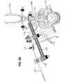
- FIG. 1is a perspective view illustration of a spine retractor and distractor device according to an embodiment of the present invention
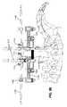
- FIGS. 2A and 2Bare end view illustrations of a spine retractor and distractor device
- FIG. 3is a top view illustration of a spine retractor and distractor device
- FIG. 4is a side view illustration of a portion of a spine, showing spinal processes
- FIGS. 5A and 5Bare side view illustrations of a spine retractor and distractor device before and during distraction of a spine
- FIGS. 6A and 6 bare perspective view illustrations of a spinal processes clamp according to an embodiment of the present invention.
- FIG. 7is a top view illustration of a spine retractor and distractor device, showing distraction pliers engaged with spinal processes clamps;
- FIG. 8is an end view illustration of a spine retractor and distractor device
- FIG. 9is a top view illustration of a spine retractor and distractor device
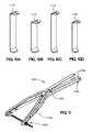
- FIG. 10is a perspective view illustration of various retractor blades according to an embodiment of the present invention.
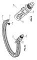
- FIG. 11is a perspective view illustration of distraction pliers according to an embodiment of the present invention.
- FIG. 12is a perspective view of the retractor ring.
- FIG. 13is a perspective view of a translation clamp.
- the systems and methods of the present inventionprovide for spinal retraction and distraction, for example, during surgical procedures on a spine.
- An exemplary spine retractor and distractor device 1000is shown in FIG. 1 .
- the spine retractor and device 1000may include a retractor assembly 1100 and a distractor assembly 1200 .
- the retractor assembly 1100is designed to hold soft tissue back from the approach and keep the incision open (see FIG. 3 ).
- the retractor assembly 1100may preferably comprise a plurality of retractor blades 1110 adjustably coupled, e.g., by fixation clamps 1120 , to a retractor ring 1130 that can be coupled to the distractor assembly 1200 .
- the retractor ring 1130may have a variable angle relative to the distraction clamps as shown by arrow 1150 in FIG. 2B , showing the angular adjustment of the retractor ring 1130 relative to the spinal processes clamps 1210 .
- the retractor ring 1130preferably having a circular shape, although any shape such as oval, square, rectangular, etc. is possible, transfers distraction forces between two spinal processes clamps 1210 , and provides a structure to mount different clamps for different components, e.g., retractor blades 1110 , light source 200 , support arm 300 , etc.
- the retractor ring 1130is not a complete enclosed ring, rather it may have two ends which allow spinal processes clamps 1210 to be attached.
- the retractor ring 1130 with a variable angle, as shown in FIGS. 7-9may have a cross section that allows the assembly of different clamps, such as spinal processes clamps 1210 (discussed later).
- the angle of the spinal processes clamps 1210 with respect to the retractor ring 1130may be adjusted (discussed later).
- the retractor ring 1130may or may not include an adjustable angle feature.
- a support arm 300 which attaches to the retractor ring 1130ensures a reference marker for the patient.
- the retractor ring 1130may preferably be made of a light and stable material, e.g. aluminum, stainless steel, PEEK (polyetheretherketone), or carbon fiber composite.
- the fixation clamps 1120are connected to the retractor blades 1110 via a rod 1140 and screw 1141 , allowing different degrees of freedom for the retractor blades 1110 .
- the fixation clamps 1120may also be utilized to hold additional components, such as for example light source 200 (see FIG. 7 ) and/or a camera (not shown).
- a support arm 300 for holding the position reference to the patientis shown in FIG. 8 .
- the retraction blades 1110may be mounted as appropriate for the surgical procedure and the patient's anatomy.
- the retractor blades 1110(as shown in FIG. 2A ) may preferably have different lengths and strengths to provide a choice to the surgeon. Depending on the application, the surgeon is able to select the most appropriate retractor blades 1110 for the situation. Individual anatomy features of the patient requires different degrees of freedom to allow the retractor blades 1110 to function properly.
- retractor blades 1110may be mounted on various positions on the retractor ring 1130 to provide different degrees of freedom.
- the retractor blades 1110hold the soft tissue back and keep the approach to the spinal column relatively clear. Further, the retractor blades may be bendable in order to adapt to soft tissue structures.
- the spine retractor and distractor device 1000also is able to perform distraction using the spinal processes 11 , which are illustrated in FIG. 4 .
- Distractionis possible because the retractor ring 1130 provides the necessary support to two or more spinal processes clamps 1210 .
- an adequate distraction forcecan be applied to the spinal processes 11 as shown in FIG. 5A , or the spinal processes clamps 1210 .
- the distraction movementas shown in FIG. 5B , is a combination of translation and rotation of the vertebrae and consequently opens a foramen for implant insertion.
- the spine retractor and distractor device 1000includes a distractor assembly 1200 which may comprise two or more spinal processes clamps 1210 , preferably with locking mechanisms 1211 (see FIGS. 2A and 6A ), and distraction pliers 1220 (see FIG. 11 for an example) configured to engage the spinal processes clamps 1210 .
- a spinal processes clamp or pliers 1210for attaching onto the spinal processes 11 , is shown in FIGS. 6A and 6B .
- the spinal processes clamp 1210clamps to the spinal processes 11 and may provide for application of the distraction force to the spine.
- the spinal processes clamps 1210may grip the spinal processes 11 and can include a locking mechanism 1211 .
- the spinal processes clamps 1210allow for fixation of the retractor ring 1130 .
- the spinal processes clamps 1210have a translation guide 1213 ( FIG. 6B ) for guidance of the translation clamps 1220 which form a connection between the spinal processes clamps 1210 and the retractor ring 1130 .
- the translation guide 1213may be connected to the spinal processes clamp 1210 by a pin/distraction sphere 1212 which allows the translation guide 1213 to rotate about the pin 1212 .
- the translation clamp 1220may have an opening or guide 1222 which preferably is a dovetail guide, although other configurations are contemplated, for attaching onto the translation guide 1213 of the spinal processes clamp 1210 .
- the translation clamp 1220may move along the length of the translation guide 1213 .
- the retractor ring 1130may have two ends that allow spinal process clamps 1210 to be attached. Each end 1131 , 1132 of the retractor ring 1130 may have a set screw 1133 for attaching a translation clamp 1220 ( FIG. 13 ) through an opening 1221 to the retractor ring 1130 .
- the translation clamp 1220may be secured to the retractor ring 1130 and set screw 1133 by a locking nut 1134 .
- the translation clamp 1220has rotation means 1221 allowing rotation between the spinal processes clamps 1210 and the retractor ring 1130 .
- Distraction tool or pliers 1230may be used to apply a distraction force to the spinal processes 11 , e.g., by way of the spinal processes clamps 1210 .
- the distraction toolmay be any tool or device capable of being disposed between two or more spinal processes 11 , contacting or engaging the spinal processes clamps 1210 , and applying an outward force to spread the spinal processes clamps 1210 apart. Because each spinal processes clamp 1210 is secured to a spinal processes 11 , spreading the spinal processes clamps 1210 results in distraction of the spinal processes 11 and the corresponding vertebrae. In the embodiment shown in FIG.
- suitable distraction pliers 1230may include a pair of spreadable extensions 1235 operated, for example, by a handle 1233 and a hinge mechanism 1234 .
- Each of the extensions 1235may include an interface 1231 , e.g., a depression, notch or other feature, configured to mate with a corresponding interface on a spinal processes clamp 1210 , e.g., a distraction sphere 1212 as shown in FIG. 6A .
- a locking mechanism 1232allows for a constant distraction force to be applied, without the surgeon maintaining a grip on the handle 1233 of the distraction pliers 1230 .
- FIGS. 2A and 2BA method of using the spine retractor and distractor device 1000 is depicted in FIGS. 2A and 2B .
- a surgeonmounts and locks two or more spinal processes clamps 1210 onto one or more spinal processes 11 .
- the surgeonthen attaches the retractor ring 1130 to the translation guide 1213 (as shown in FIG. 6B ) on the spinal processes clamp 1210 by use of translation clamps 1220 .
- each end of the retractor ring 1130is preferably attached to one of the spinal processes clamps 1210 .
- the angle of the retractor ring 1130may then be adjusted. The angle may be adjusted by rotating the translation guide about an axis extending through the translation guide.
- a support arm 1250 with an adjustable anglemay also be used to assist with the adjustment of the angle of the retractor ring 1130 .
- Retractor blades 1110are attached with fixation clamps 1120 via rods 1140 and screws 1141 to the retractor ring 1130 .
- the retractor blades 1130 and rods 1140may be adjusted as necessary.
- the retractor blades 1110are positioned to retract the soft tissue around the spinal processes 11 to expose a spine segment. This is accomplished by engaging the soft tissue with one or more retractor blades 1130 . The surgeon may then distract the spinal segment using the distraction pliers 1230 engaged with one or more spinal processes clamps 1210 .
- extensions 1235 of the distraction pliers 1230may be disposed between the spinal processes clamps 1210 (as shown in FIGS. 7 and 8 ), and the distraction force can be applied by squeezing the handle portion 1233 of the distraction pliers 1230 , which spreads the extension portion 1235 . This corresponding distracts the spinal processes clamps 1210 .
- the distraction forceis a non-linear force, to maintain the reference with the patient, the translation clamp 1220 may correspondingly rotate via the rotating means 1221 as the spinal processes clamps 1210 are distracted.
- a locking mechanism 1232as shown in FIG. 11 , can be used to maintain the distraction force or position, e.g., by maintaining the handle 1233 of the distraction pliers 1230 in a particular state.
- the distraction pliers 1230may be applied and used temporarily for the distraction movement.
- the distraction plierscan be fixed to the spine retractor and distractor device 1000 .
- One skilled in the artwill appreciate that other distraction pliers, tools or mechanisms may be employed to impart a distraction force to one or more of the spinal processes clamps 1210 or one or more spinal segments.
- the various components of the spine retractor and device 1000may be made of alternative materials, for example PEEK or other materials in order to provide radiolucent properties for x-rays.
- distractioncan be attained over structures other than spinal processes 11 .
- the systemcan also be utilized with pre assembled clamps or fixed clamps.
- the spinal processes clamps 1210may be designed with a single translation guide 1213 , e.g., where just one clamp is fixed.
- the spinal processes clamps 1210may have more than two points (tips) 1214 .
- the spinal processes clamps 1210 and distractor pliers 1230may have detachable handles.
- the spine retractor and distractor device 1000may be used without the retractor blades, but with a stand alone retractor.
- One or more additional guides for an implant holdermay be used.
- Additional supports for the spinal processes clampsmay or may not also be used.
- spine retractor and device and methods described hereinmay be modified and used for other approaches in trauma or craniomaxillofacial (CMF) surgery.
- CMFcraniomaxillofacial
- Other embodimentsmay be used in procedures involving the cervical spine.
Landscapes
- Health & Medical Sciences (AREA)
- Life Sciences & Earth Sciences (AREA)
- Surgery (AREA)
- Heart & Thoracic Surgery (AREA)
- Engineering & Computer Science (AREA)
- Biomedical Technology (AREA)
- Nuclear Medicine, Radiotherapy & Molecular Imaging (AREA)
- Medical Informatics (AREA)
- Molecular Biology (AREA)
- Animal Behavior & Ethology (AREA)
- General Health & Medical Sciences (AREA)
- Public Health (AREA)
- Veterinary Medicine (AREA)
- Surgical Instruments (AREA)
- Prostheses (AREA)
Abstract
Description
- 1. Create an approach to the selected disc;
- 2. Complete or partial removal of the selected disc or disc material (annulus and/or nucleus), e.g., discectomy; and
- 3. Insert the total disc replacement devices, or intervertebral spacers, or fixation devices such as screws, plates, rod systems, etc.
- the reference could be lost if the patient is moved on the table, whereas the nerve root is “bound” to the table; and
- the surgeon must manipulate outside the conventional sterile area, i.e. underneath the sterile covers on the OR table, which might contaminate the sterile incision area.
Claims (18)
Priority Applications (1)
| Application Number | Priority Date | Filing Date | Title |
|---|---|---|---|
| US12/066,226US8911364B2 (en) | 2005-09-08 | 2006-09-08 | Spine retractor and distractor device |
Applications Claiming Priority (3)
| Application Number | Priority Date | Filing Date | Title |
|---|---|---|---|
| US71518905P | 2005-09-08 | 2005-09-08 | |
| US12/066,226US8911364B2 (en) | 2005-09-08 | 2006-09-08 | Spine retractor and distractor device |
| PCT/IB2006/004145WO2007085909A2 (en) | 2005-09-08 | 2006-09-08 | Spine retractor and distractor device |
Publications (2)
| Publication Number | Publication Date |
|---|---|
| US20080300465A1 US20080300465A1 (en) | 2008-12-04 |
| US8911364B2true US8911364B2 (en) | 2014-12-16 |
Family
ID=38309569
Family Applications (1)
| Application Number | Title | Priority Date | Filing Date |
|---|---|---|---|
| US12/066,226Active2030-10-26US8911364B2 (en) | 2005-09-08 | 2006-09-08 | Spine retractor and distractor device |
Country Status (2)
| Country | Link |
|---|---|
| US (1) | US8911364B2 (en) |
| WO (1) | WO2007085909A2 (en) |
Cited By (11)
| Publication number | Priority date | Publication date | Assignee | Title |
|---|---|---|---|---|
| US9951904B2 (en) | 2015-03-24 | 2018-04-24 | Stryker Corporation | Rotatable seat clamps for rail clamp |
| US10045768B2 (en) | 2014-07-06 | 2018-08-14 | Javier Garcia-Bengochea | Methods and devices for surgical access |
| US10238375B2 (en)* | 2017-07-19 | 2019-03-26 | Nuvasive, Inc. | Surgical retractor |
| US10478364B2 (en) | 2014-03-10 | 2019-11-19 | Stryker Corporation | Limb positioning system |
| US10653407B2 (en) | 2016-12-21 | 2020-05-19 | Nuvasive, Inc. | Surgical retractor |
| US10687830B2 (en) | 2015-07-06 | 2020-06-23 | Javier Garcia-Bengochea | Methods and devices for surgical access |
| US10687797B2 (en) | 2008-12-18 | 2020-06-23 | Howmedica Osteonics Corp. | Lateral access system for the lumbar spine |
| US11166709B2 (en) | 2016-08-23 | 2021-11-09 | Stryker European Operations Holdings Llc | Instrumentation and methods for the implantation of spinal implants |
| US11191532B2 (en) | 2018-03-30 | 2021-12-07 | Stryker European Operations Holdings Llc | Lateral access retractor and core insertion |
| US11523846B2 (en)* | 2020-10-09 | 2022-12-13 | Viseon, Inc. | Retractor, distractor, and camera system for cervical procedures |
| US11564674B2 (en) | 2019-11-27 | 2023-01-31 | K2M, Inc. | Lateral access system and method of use |
Families Citing this family (60)
| Publication number | Priority date | Publication date | Assignee | Title |
|---|---|---|---|---|
| EP1146816B1 (en) | 1998-12-23 | 2005-10-12 | Nuvasive Inc. | Nerve surveillance cannulae systems |
| WO2001037728A1 (en) | 1999-11-24 | 2001-05-31 | Nuvasive, Inc. | Electromyography system |
| EP1417000B1 (en) | 2001-07-11 | 2018-07-11 | Nuvasive, Inc. | System for determining nerve proximity during surgery |
| JP2005503857A (en) | 2001-09-25 | 2005-02-10 | ヌバシブ, インコーポレイテッド | Systems and methods for performing surgical procedures and surgical diagnosis |
| US7582058B1 (en) | 2002-06-26 | 2009-09-01 | Nuvasive, Inc. | Surgical access system and related methods |
| US8137284B2 (en) | 2002-10-08 | 2012-03-20 | Nuvasive, Inc. | Surgical access system and related methods |
| US7691057B2 (en) | 2003-01-16 | 2010-04-06 | Nuvasive, Inc. | Surgical access system and related methods |
| US7819801B2 (en) | 2003-02-27 | 2010-10-26 | Nuvasive, Inc. | Surgical access system and related methods |
| US7905840B2 (en) | 2003-10-17 | 2011-03-15 | Nuvasive, Inc. | Surgical access system and related methods |
| JP4463819B2 (en) | 2003-09-25 | 2010-05-19 | ヌヴァシヴ インコーポレイテッド | Surgical access system |
| US8313430B1 (en) | 2006-01-11 | 2012-11-20 | Nuvasive, Inc. | Surgical access system and related methods |
| WO2006042241A2 (en) | 2004-10-08 | 2006-04-20 | Nuvasive, Inc. | Surgical access system and related methods |
| US8328851B2 (en) | 2005-07-28 | 2012-12-11 | Nuvasive, Inc. | Total disc replacement system and related methods |
| US8911364B2 (en) | 2005-09-08 | 2014-12-16 | DePuy Synthes Products, LLC | Spine retractor and distractor device |
| US8251902B2 (en) | 2005-10-17 | 2012-08-28 | Lanx, Inc. | Pedicle guided retractor system |
| US9011441B2 (en)* | 2006-02-17 | 2015-04-21 | Paradigm Spine, L.L.C. | Method and system for performing interspinous space preparation for receiving an implant |
| US8560047B2 (en) | 2006-06-16 | 2013-10-15 | Board Of Regents Of The University Of Nebraska | Method and apparatus for computer aided surgery |
| DE202006019649U1 (en)* | 2006-12-22 | 2007-08-16 | Brainlab Ag | Navigated application guide for targeted spinal drug administration |
| JP5443474B2 (en)* | 2008-05-07 | 2014-03-19 | ジンテス ゲゼルシャフト ミット ベシュレンクテル ハフツング | Method and apparatus for lateral access to intervertebral disc space |
| AU2009329873A1 (en) | 2008-12-26 | 2011-11-03 | Scott Spann | Minimally-invasive retroperitoneal lateral approach for spinal surgery |
| US9351845B1 (en) | 2009-04-16 | 2016-05-31 | Nuvasive, Inc. | Method and apparatus for performing spine surgery |
| US8287597B1 (en) | 2009-04-16 | 2012-10-16 | Nuvasive, Inc. | Method and apparatus for performing spine surgery |
| ITPI20090044A1 (en) | 2009-04-22 | 2010-10-23 | Cousin Biotech S A S | INSTRUMENTARY FOR THE INSTALLATION OF AN INTERVERTEBRAL PROSTHESIS |
| TR200907282A2 (en) | 2009-09-24 | 2010-07-21 | Cevdet Caner Tevfi̇k | Adjustable retractor system and fusion set that can be connected to the table. |
| USD630736S1 (en)* | 2010-03-27 | 2011-01-11 | Shyh-Jen Wang | Open-end ratchet rack of retractor |
| US8827902B2 (en) | 2010-08-16 | 2014-09-09 | Donald David DIETZE, Jr. | Surgical instrument system and method for providing retraction and vertebral distraction |
| US8790406B1 (en) | 2011-04-01 | 2014-07-29 | William D. Smith | Systems and methods for performing spine surgery |
| US9498231B2 (en) | 2011-06-27 | 2016-11-22 | Board Of Regents Of The University Of Nebraska | On-board tool tracking system and methods of computer assisted surgery |
| US11911117B2 (en) | 2011-06-27 | 2024-02-27 | Board Of Regents Of The University Of Nebraska | On-board tool tracking system and methods of computer assisted surgery |
| CN103764061B (en) | 2011-06-27 | 2017-03-08 | 内布拉斯加大学评议会 | On Tool Tracking System and Computer Assisted Surgery Method |
| USD658286S1 (en)* | 2011-07-29 | 2012-04-24 | Greatbatch Ltd. | Double ended retractor |
| CN103987326B (en) | 2011-08-19 | 2016-06-08 | 诺威适有限公司 | Surgical retractor system and method of use |
| EP2750611B1 (en) | 2011-08-31 | 2016-11-23 | Lanx, Inc. | Lateral retractor system |
| US9198765B1 (en) | 2011-10-31 | 2015-12-01 | Nuvasive, Inc. | Expandable spinal fusion implants and related methods |
| US20130197313A1 (en)* | 2012-01-31 | 2013-08-01 | Shaw P. Wan | Surgical retractor with light |
| US8231528B1 (en) | 2012-03-13 | 2012-07-31 | Globus Medical, Inc. | System and method for retracting body tissue |
| US9642606B2 (en)* | 2012-06-27 | 2017-05-09 | Camplex, Inc. | Surgical visualization system |
| US9615728B2 (en) | 2012-06-27 | 2017-04-11 | Camplex, Inc. | Surgical visualization system with camera tracking |
| US9782159B2 (en) | 2013-03-13 | 2017-10-10 | Camplex, Inc. | Surgical visualization systems |
| US10105149B2 (en) | 2013-03-15 | 2018-10-23 | Board Of Regents Of The University Of Nebraska | On-board tool tracking system and methods of computer assisted surgery |
| US9125587B2 (en) | 2013-03-15 | 2015-09-08 | DePuy Synthes Products, Inc. | Surgical retractors |
| US10028651B2 (en) | 2013-09-20 | 2018-07-24 | Camplex, Inc. | Surgical visualization systems and displays |
| EP3046458B1 (en) | 2013-09-20 | 2020-10-21 | Camplex, Inc. | Surgical visualization systems |
| TWI533834B (en)* | 2013-12-10 | 2016-05-21 | Ying-Jie Su | Magnetic manipulation of the surgical lighting device and a hand with a lighting function Assisted system |
| WO2015134367A1 (en)* | 2014-03-03 | 2015-09-11 | Alphatec Spine, Inc. | Soft tissue retractor |
| US20150250464A1 (en) | 2014-03-07 | 2015-09-10 | John Song | Spinal Compressor and Distractor |
| US9724137B2 (en)* | 2014-03-19 | 2017-08-08 | Warsaw Orthopedic, Inc. | Surgical instrumentation and method |
| EP3226799A4 (en) | 2014-12-05 | 2018-07-25 | Camplex, Inc. | Surgical visualization systems and displays |
| WO2016154589A1 (en) | 2015-03-25 | 2016-09-29 | Camplex, Inc. | Surgical visualization systems and displays |
| WO2017091704A1 (en) | 2015-11-25 | 2017-06-01 | Camplex, Inc. | Surgical visualization systems and displays |
| CN105640598B (en)* | 2016-03-10 | 2018-07-03 | 徐仲阳 | A kind of minimally invasive retractor of lumbar vertebrae three-dimensional |
| WO2018208691A1 (en) | 2017-05-08 | 2018-11-15 | Camplex, Inc. | Variable light source |
| US10863975B2 (en) | 2017-07-14 | 2020-12-15 | Carefusion 2200, Inc. | Adjustable length, reusable retraction blades |
| US11534153B2 (en) | 2017-09-05 | 2022-12-27 | Nicholas Qandah | Retractor system |
| WO2019152523A1 (en)* | 2018-01-30 | 2019-08-08 | Rebound Therapeutics Corporation | Devices and method for access and visualization for lumbar interbody fusion (lif) |
| CN109106409A (en)* | 2018-09-12 | 2019-01-01 | 昆明医科大学第二附属医院 | A kind of hepatobiliary surgery auxiliary device |
| WO2021053392A2 (en)* | 2019-09-20 | 2021-03-25 | Axis Spine Technologies Ltd. | Radiolucent surgical retractor |
| CN113288353A (en)* | 2021-05-14 | 2021-08-24 | 无锡市闻泰百得医疗器械有限公司 | Minimally invasive spinal access |
| CN113413222B (en)* | 2021-06-22 | 2023-03-28 | 昆明市延安医院 | Micro-root tip is 3D for operation to print drag hook |
| CN114848055B (en)* | 2022-05-13 | 2025-08-12 | 复旦大学附属中山医院 | Perineum visual field exposing device |
Citations (8)
| Publication number | Priority date | Publication date | Assignee | Title |
|---|---|---|---|---|
| US20020013514A1 (en)* | 2000-04-14 | 2002-01-31 | Brau Salvador A. | Surgical retractor and related surgical approach to access the anterior lumbar region |
| US20020165550A1 (en)* | 1999-10-21 | 2002-11-07 | George Frey | Devices and techniques for a posterior lateral disc space approach |
| US20040002629A1 (en)* | 2002-06-26 | 2004-01-01 | Branch Charles L. | Instruments and methods for minimally invasive tissue retraction and surgery |
| WO2004047650A2 (en) | 2002-11-23 | 2004-06-10 | Sdgi Holdings, Inc. | Istraction and retraction system for spinal surgery |
| US20050075644A1 (en) | 2003-10-02 | 2005-04-07 | Dipoto Gene | Methods and apparatuses for minimally invasive replacement of intervertebral discs |
| US20050277812A1 (en)* | 2004-06-14 | 2005-12-15 | Myles Robert T | Minimally invasive surgical spinal exposure system |
| US7232411B2 (en)* | 2001-04-20 | 2007-06-19 | Integra Lifesciences Corporation | Radiolucent retractor and related components |
| WO2007085909A2 (en) | 2005-09-08 | 2007-08-02 | Synthes (Usa) | Spine retractor and distractor device |
- 2006
- 2006-09-08USUS12/066,226patent/US8911364B2/enactiveActive
- 2006-09-08WOPCT/IB2006/004145patent/WO2007085909A2/enactiveApplication Filing
Patent Citations (9)
| Publication number | Priority date | Publication date | Assignee | Title |
|---|---|---|---|---|
| US20020165550A1 (en)* | 1999-10-21 | 2002-11-07 | George Frey | Devices and techniques for a posterior lateral disc space approach |
| US20020013514A1 (en)* | 2000-04-14 | 2002-01-31 | Brau Salvador A. | Surgical retractor and related surgical approach to access the anterior lumbar region |
| US7232411B2 (en)* | 2001-04-20 | 2007-06-19 | Integra Lifesciences Corporation | Radiolucent retractor and related components |
| US20040002629A1 (en)* | 2002-06-26 | 2004-01-01 | Branch Charles L. | Instruments and methods for minimally invasive tissue retraction and surgery |
| WO2004047650A2 (en) | 2002-11-23 | 2004-06-10 | Sdgi Holdings, Inc. | Istraction and retraction system for spinal surgery |
| US20040230191A1 (en)* | 2002-11-23 | 2004-11-18 | George Frey | Distraction and retraction system for spinal surgery |
| US20050075644A1 (en) | 2003-10-02 | 2005-04-07 | Dipoto Gene | Methods and apparatuses for minimally invasive replacement of intervertebral discs |
| US20050277812A1 (en)* | 2004-06-14 | 2005-12-15 | Myles Robert T | Minimally invasive surgical spinal exposure system |
| WO2007085909A2 (en) | 2005-09-08 | 2007-08-02 | Synthes (Usa) | Spine retractor and distractor device |
Non-Patent Citations (2)
| Title |
|---|
| International Search Report, dated Dec. 5, 2007, issued in International Application No. PCT/IB2006/004145. |
| U.S. Appl. No. 60/715,189, filed Sep. 8, 2005, Feigenwinter et al. |
Cited By (23)
| Publication number | Priority date | Publication date | Assignee | Title |
|---|---|---|---|---|
| US10687797B2 (en) | 2008-12-18 | 2020-06-23 | Howmedica Osteonics Corp. | Lateral access system for the lumbar spine |
| US11925342B2 (en) | 2008-12-18 | 2024-03-12 | Howmedica Osteonics Corp. | Lateral access system for the lumbar spine |
| US10478364B2 (en) | 2014-03-10 | 2019-11-19 | Stryker Corporation | Limb positioning system |
| US10045768B2 (en) | 2014-07-06 | 2018-08-14 | Javier Garcia-Bengochea | Methods and devices for surgical access |
| US12349891B2 (en) | 2014-07-06 | 2025-07-08 | Jgmg Bengochea, Llc | Apparatus for positioning a patient during surgery to maximize access to a surgical site of interest |
| US12070202B2 (en) | 2014-07-06 | 2024-08-27 | Jgmg Bengochea, Llc | Methods and devices for surgical access |
| US9951904B2 (en) | 2015-03-24 | 2018-04-24 | Stryker Corporation | Rotatable seat clamps for rail clamp |
| US10687830B2 (en) | 2015-07-06 | 2020-06-23 | Javier Garcia-Bengochea | Methods and devices for surgical access |
| US12133643B2 (en) | 2016-08-23 | 2024-11-05 | Stryker European Operations Holdings Llc | Instrumentation and methods for the implantation of spinal implants |
| US11166709B2 (en) | 2016-08-23 | 2021-11-09 | Stryker European Operations Holdings Llc | Instrumentation and methods for the implantation of spinal implants |
| US11484299B2 (en) | 2016-12-21 | 2022-11-01 | Nuvasive, Inc. | Surgical retractor |
| US11607209B2 (en) | 2016-12-21 | 2023-03-21 | Nuvasive, Inc. | Surgical retractor |
| US11707269B2 (en) | 2016-12-21 | 2023-07-25 | Nuvasive, Inc. | Surgical retractor |
| US10653407B2 (en) | 2016-12-21 | 2020-05-19 | Nuvasive, Inc. | Surgical retractor |
| US12161315B2 (en) | 2016-12-21 | 2024-12-10 | Globus Medical Inc. | Surgical retractor |
| US11759195B2 (en) | 2017-07-19 | 2023-09-19 | Nuvasive, Inc. | Surgical procedure with retractor |
| US11889999B2 (en) | 2017-07-19 | 2024-02-06 | Nuvasive, Inc. | Surgical procedure with retractor |
| US11109851B2 (en) | 2017-07-19 | 2021-09-07 | Nuvasive, Inc. | Surgical retractor |
| US10238375B2 (en)* | 2017-07-19 | 2019-03-26 | Nuvasive, Inc. | Surgical retractor |
| US11911016B2 (en) | 2018-03-30 | 2024-02-27 | Stryker European Operations Holdings Llc | Lateral access retractor and core insertion |
| US11191532B2 (en) | 2018-03-30 | 2021-12-07 | Stryker European Operations Holdings Llc | Lateral access retractor and core insertion |
| US11564674B2 (en) | 2019-11-27 | 2023-01-31 | K2M, Inc. | Lateral access system and method of use |
| US11523846B2 (en)* | 2020-10-09 | 2022-12-13 | Viseon, Inc. | Retractor, distractor, and camera system for cervical procedures |
Also Published As
| Publication number | Publication date |
|---|---|
| US20080300465A1 (en) | 2008-12-04 |
| WO2007085909A3 (en) | 2008-03-13 |
| WO2007085909A2 (en) | 2007-08-02 |
Similar Documents
| Publication | Publication Date | Title |
|---|---|---|
| US8911364B2 (en) | Spine retractor and distractor device | |
| US10603026B2 (en) | Devices and systems for surgical retraction | |
| US8721536B2 (en) | Arcuate surgical guidance system and methods | |
| US9861496B2 (en) | Apparatus and method of spinal implant and fusion | |
| US20070191856A1 (en) | Adjustable height spinal distractor | |
| US8840621B2 (en) | Spinal access systems and methods | |
| US7776095B2 (en) | Spinal system and method including lateral approach | |
| US7763078B2 (en) | Spinal device including lateral approach | |
| US9289248B2 (en) | Assembly with offset allowing vertebral distraction by axial rotation of a concentric member | |
| EP3958761B1 (en) | Surgical system | |
| CA2668194A1 (en) | Instrumentation and method for providing surgical access to a spine | |
| US20090062619A1 (en) | Methods and apparatus for surgical retraction | |
| WO2009094493A2 (en) | Spinal access systems and methods | |
| RU2212865C1 (en) | Device for implanting lumbar intervertebral disk prosthesis | |
| US11723643B2 (en) | Distraction and retraction assembly incorporating locking feature |
Legal Events
| Date | Code | Title | Description |
|---|---|---|---|
| AS | Assignment | Owner name:SYNTHES GMBH, SWITZERLAND Free format text:ASSIGNMENT OF ASSIGNORS INTEREST;ASSIGNORS:FEIGENWINTER, GREGOR;LECHMANN, BEAT;BUERKI, ROGER;AND OTHERS;SIGNING DATES FROM 20080423 TO 20080502;REEL/FRAME:021156/0358 Owner name:SYNTHES (U.S.A.), PENNSYLVANIA Free format text:ASSIGNMENT OF ASSIGNORS INTEREST;ASSIGNOR:SYNTHES GMBH;REEL/FRAME:021156/0526 Effective date:20080507 Owner name:SYNTHES GMBH, SWITZERLAND Free format text:ASSIGNMENT OF ASSIGNORS INTEREST;ASSIGNORS:FEIGENWINTER, GREGOR;LECHMANN, BEAT;BUERKI, ROGER;AND OTHERS;REEL/FRAME:021156/0358;SIGNING DATES FROM 20080423 TO 20080502 | |
| AS | Assignment | Owner name:SYNTHES USA, LLC, PENNSYLVANIA Free format text:CHANGE OF NAME;ASSIGNOR:SYNTHES (U.S.A.);REEL/FRAME:022826/0140 Effective date:20081223 Owner name:SYNTHES USA, LLC,PENNSYLVANIA Free format text:CHANGE OF NAME;ASSIGNOR:SYNTHES (U.S.A.);REEL/FRAME:022826/0140 Effective date:20081223 | |
| AS | Assignment | Owner name:DEPUY SPINE, LLC, MASSACHUSETTS Free format text:ASSIGNMENT OF ASSIGNORS INTEREST;ASSIGNOR:SYNTHES USA, LLC;REEL/FRAME:030358/0945 Effective date:20121230 Owner name:DEPUY SYNTHES PRODUCTS, LLC, MASSACHUSETTS Free format text:CHANGE OF NAME;ASSIGNOR:HAND INNOVATIONS LLC;REEL/FRAME:030359/0036 Effective date:20121231 Owner name:HAND INNOVATIONS LLC, FLORIDA Free format text:ASSIGNMENT OF ASSIGNORS INTEREST;ASSIGNOR:DEPUY SPINE, LLC;REEL/FRAME:030359/0001 Effective date:20121230 | |
| STCF | Information on status: patent grant | Free format text:PATENTED CASE | |
| AS | Assignment | Owner name:HAND INNOVATIONS LLC, FLORIDA Free format text:CORRECTIVE ASSIGNMENT TO CORRECT THE INCORRECT APPL. NO. 13/486,591 PREVIOUSLY RECORDED AT REEL: 030359 FRAME: 0001. ASSIGNOR(S) HEREBY CONFIRMS THE ASSIGNMENT;ASSIGNOR:DEPUY SPINE, LLC;REEL/FRAME:042621/0565 Effective date:20121230 | |
| AS | Assignment | Owner name:DEPUY SPINE, LLC, MASSACHUSETTS Free format text:CORRECTIVE ASSIGNMENT TO CORRECT THE INCORRECT APPLICATION NO. US 13/486,591 PREVIOUSLY RECORDED ON REEL 030358 FRAME 0945. ASSIGNOR(S) HEREBY CONFIRMS THE ASSIGNMENT;ASSIGNOR:SYNTHES USA, LLC;REEL/FRAME:042687/0849 Effective date:20121230 | |
| MAFP | Maintenance fee payment | Free format text:PAYMENT OF MAINTENANCE FEE, 4TH YEAR, LARGE ENTITY (ORIGINAL EVENT CODE: M1551) Year of fee payment:4 | |
| MAFP | Maintenance fee payment | Free format text:PAYMENT OF MAINTENANCE FEE, 8TH YEAR, LARGE ENTITY (ORIGINAL EVENT CODE: M1552); ENTITY STATUS OF PATENT OWNER: LARGE ENTITY Year of fee payment:8 |