US8910556B2 - Bottom hole firing head and method - Google Patents
Bottom hole firing head and methodDownload PDFInfo
- Publication number
- US8910556B2 US8910556B2US13/694,319US201213694319AUS8910556B2US 8910556 B2US8910556 B2US 8910556B2US 201213694319 AUS201213694319 AUS 201213694319AUS 8910556 B2US8910556 B2US 8910556B2
- Authority
- US
- United States
- Prior art keywords
- piston
- fluid
- well
- sub
- bore
- Prior art date
- Legal status (The legal status is an assumption and is not a legal conclusion. Google has not performed a legal analysis and makes no representation as to the accuracy of the status listed.)
- Active, expires
Links
Images


Classifications
- E—FIXED CONSTRUCTIONS
- E21—EARTH OR ROCK DRILLING; MINING
- E21B—EARTH OR ROCK DRILLING; OBTAINING OIL, GAS, WATER, SOLUBLE OR MELTABLE MATERIALS OR A SLURRY OF MINERALS FROM WELLS
- E21B43/00—Methods or apparatus for obtaining oil, gas, water, soluble or meltable materials or a slurry of minerals from wells
- E21B43/11—Perforators; Permeators
- E21B43/116—Gun or shaped-charge perforators
- E21B43/1185—Ignition systems
- E21B43/11852—Ignition systems hydraulically actuated
- E—FIXED CONSTRUCTIONS
- E21—EARTH OR ROCK DRILLING; MINING
- E21B—EARTH OR ROCK DRILLING; OBTAINING OIL, GAS, WATER, SOLUBLE OR MELTABLE MATERIALS OR A SLURRY OF MINERALS FROM WELLS
- E21B43/00—Methods or apparatus for obtaining oil, gas, water, soluble or meltable materials or a slurry of minerals from wells
- E21B43/11—Perforators; Permeators
- E21B43/116—Gun or shaped-charge perforators
- E21B43/1185—Ignition systems
- E21B43/11855—Ignition systems mechanically actuated, e.g. by movement of a wireline or a drop-bar
- E—FIXED CONSTRUCTIONS
- E21—EARTH OR ROCK DRILLING; MINING
- E21B—EARTH OR ROCK DRILLING; OBTAINING OIL, GAS, WATER, SOLUBLE OR MELTABLE MATERIALS OR A SLURRY OF MINERALS FROM WELLS
- E21B29/00—Cutting or destroying pipes, packers, plugs or wire lines, located in boreholes or wells, e.g. cutting of damaged pipes, of windows; Deforming of pipes in boreholes or wells; Reconditioning of well casings while in the ground
- E21B29/02—Cutting or destroying pipes, packers, plugs or wire lines, located in boreholes or wells, e.g. cutting of damaged pipes, of windows; Deforming of pipes in boreholes or wells; Reconditioning of well casings while in the ground by explosives or by thermal or chemical means
- E—FIXED CONSTRUCTIONS
- E21—EARTH OR ROCK DRILLING; MINING
- E21B—EARTH OR ROCK DRILLING; OBTAINING OIL, GAS, WATER, SOLUBLE OR MELTABLE MATERIALS OR A SLURRY OF MINERALS FROM WELLS
- E21B34/00—Valve arrangements for boreholes or wells
- E21B34/06—Valve arrangements for boreholes or wells in wells
- E21B34/12—Valve arrangements for boreholes or wells in wells operated by movement of casings or tubings
- E—FIXED CONSTRUCTIONS
- E21—EARTH OR ROCK DRILLING; MINING
- E21B—EARTH OR ROCK DRILLING; OBTAINING OIL, GAS, WATER, SOLUBLE OR MELTABLE MATERIALS OR A SLURRY OF MINERALS FROM WELLS
- E21B2200/00—Special features related to earth drilling for obtaining oil, gas or water
- E21B2200/06—Sleeve valves
Definitions
- the present inventionrelates generally to methods and apparatus for detonating downhole explosives such as well perforating guns proximate of well terminus structure.
- the open well boreis often cased to maintain the integrity of the production face.
- Some well completion proceduresmay include bottom hole plug structure to seal the well bore below a fluid mineral bearing production zone. That portion of the casing length adjacent to the production zone is perforated to admit the flow of in situ formation fluids into the casing bore.
- the in situ fluidmay be produced from an uncased production face. In either case, the in situ formation fluid is delivered to the well surface along the bore of a production tube that is suspended from the surface along the axial length of the well.
- the production tubeoften penetrates a packer structure which seals the annulus between the outer perimeter of the production tube and the interior of the casing or raw bore wall above the formation fluid production zone. Below the formation production zone, the production tube may be plugged.
- the production tube wallis perforated along that length section proximate of the formation production face to admit entry of formation fluid into the tube flow bore.
- Pipe and casing perforations such as described aboveare often produced by a multiplicity of shaped charge explosives distributed along the length and around the perimeter of a cylindrical perforating gun.
- Shaped chargesare usually fabricated of high order explosive that are, in some circumstances, difficult to detonate.
- numerous techniqueshave been used to detonate such shaped charges.
- perforating gunshave been actuated electrically, by means of a drop bar mechanism and by fluid pressure upon a firing head. Many complex factors contribute to a decision regarding which of these firing mechanisms is most appropriate for a specific well completion.
- the present inventionaddresses a method and apparatus for activating the firing head by fluid pressure.
- One object of the present inventionis a fluid pressure activated firing head that does not impose increased fluid pressure upon the perforating gun and the surrounding well environment additional to the in situ well pressure additional to the in situ well pressure.
- Firing head activation pressureis generated by a piston-cylinder mechanism positioned axially adjacent to a pressure responsive firing head.
- a piston rod element of the piston-cylinder mechanismprojects beyond the bottom distal end of a perforating gun and firing head assembly.
- a bore plug or packerAt the bottom end of the well production tube or casing is a bore plug or packer.
- the projecting piston rodis axially aligned to engage the bore plug in support of the gun weight upon the plug and secured in place by one or more calibrated shear fasteners such as screws or pins.
- a safety subis positioned in the gun assembly between the piston-cylinder sub and the firing head to prevent premature gun detonation as the assembly descends along the well bore.
- the safety subcomprises venting apertures in the high pressure cylinder volume to divert unintentionally or prematurely displaced fluid. Venting apertures in the safety sub housing are paired with apertures in a well pressure actuated piston sleeve.
- any premature displacement of the firing pressure pistondisplaces a corresponding volume of well fluid in to the surrounding well annulus.
- in situ fluid pressurecloses the safety sub apertures and permits the generation of detonation pressure against the firing head.
- a springre-cocks the piston in the event of premature displacement so as to enable firing once the venting apertures are closed.
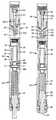
- FIG. 1is partial section of a well with the invention positioned proximate of the well bottom
- FIG. 2is a section view of the invention prepared for well run-in and prior to operation.
- FIG. 3is a section view of the invention showing the operational sequence following a premature displacement of the firing pressure piston.
- FIG. 4is a section view of the invention showing distinctive operating events as a predetermined detonation depth is approached.
- FIG. 5is a section view of the invention showing distinctive operating events at the moment of firing head detonation.
- tubingmay refer to drill pipe, completion tubing, production tubing, casing or other similar tubular members suitable for forming the flow paths described and illustrated herein.
- connections between tubular or housing memberswill be by way of conventional “pin” and “box” threaded couplings.
- FIG. 1illustrates in partial section the lower distal end of a production tube 10 having the bottom end of a perforating gun assembly positioned within the tube bore.
- the lower end of the tube 10is sealed by a packer or bottom hole bore plug 12 .
- the perforating gun 14comprises a multiplicity of shaped charges of explosive material 16 . When detonated, these charges 16 explosively decompose with a linearly directed stream of high temperature gas. These high temperature gas streams perforate the walls of the tube 10 to provide fluid flow channels into the tube bore for in situ fluid flow up the tube to the surface.
- the shaped chargesare traditionally detonated by a primer cord, the initiation of which is generated by a low order percussion detonator.
- the detonator and percussion mechanismis assembled within the firing head 18 in a manner such as described in detail by U.S. Pat. No. 4,901,802 to F. R. George et al.
- a free piston carried firing pinis secured within a cylinder by calibrated shear retainers such as pins or screws.
- One face of the pistonis exposed to a high pressure fluid source whereas the opposite face of the piston is exposed to a sealed, low pressure volume.
- a pressure generating piston sub 20is positioned at the distal end of the gun assembly. Between the piston sub 20 and the firing head 18 is a safety sub 30 .
- the firing pressure piston 22is secured by calibrated shear fasteners such as pins or screws 23 at a retracted position of the piston face below cylinder relief apertures 25 .
- Piston rod 24is a reduced diameter extension from the piston 22 and projects beyond the distal end 28 of the tube wall 27 . Venting apertures 26 below the piston 22 provide equalization pressure on the piston for well run-in.
- a helical spring 45 disposed within the extended cylinder bore 21bears upon the face of piston 22 to bias the piston toward the retracted position shown. Configured as FIG. 2 , all dynamic elements of the invention are pressure balanced.
- the gun assemblyis lowered along the well bore in the configuration represented by FIG. 2 until the distal end of the piston rod 24 engages the bottom hole bore plug 12 .
- a safety sub 30is positioned between the firing piston sub 20 and the firing head 18 .
- the safety sub 30comprises a tubular housing 31 having strategically positioned and sized venting apertures 35 .
- the central bore 32 of the housing 31guides the axial translation of a hollow bore valve sleeve 33 having a greater outside diameter at the lower end seal zone 39 than that of the upper end seal zone 38 .
- the length of the axial flow bore 34extends past the upper end of the sleeve 33 . So long as the sleeve is in the run-in position shown by FIG. 3 , the venting apertures 35 are open between the axial flow bore 34 and the surrounding well annulus.
- a cylindrical tension link 36is secured to both, the valve sleeve 33 and the housing of piston sub 20 in coaxial alignment with the flow bore 34 .
- the tension link 36is circumferentially scored between the sleeve 33 and the piston sub housing 20 to separate in tensile failure at a predetermined pressure differential between the in situ well pressure and a reference chamber 37 surrounding valve sleeve 33 between upper and lower sleeve seal zones 38 and 39 , respectively.
- Radial apertures 40 through the sleeve 33 wallprovide pressure communication between the axial flow bore 34 and the external perimeter of the sleeve below the lower seal zone 39 .
- FIG. 4illustrates an upward shift of the valve sleeve 33 due to a tensile failure of the tension link 36 .
- This upward translation of the sleeve 33closes the venting apertures 35 .
- the severed linkreleases the valve sleeve 33 to shift upwardly and close the venting apertures 35 .
- the upper portion of the tension link 36 a secured to the valve sleeve 33remains with the valve sleeve whereas the lower portion of the link 36 b remains with the piston sub housing.
- valve sleeve 33When the valve sleeve 33 reaches the upper end of the central bore 32 to close the venting apertures 35 , a spring biased C-ring 41 closes into the bore 32 space prevent the valve sleeve 33 from returning to its original position. The tool is now armed for the final detonation event.
- the final detonation eventis engagement of the bottom hole bore plug 12 by the piston rod 24 .
- the pistonis pushed against the bias of spring 45 past the venting apertures 25 .
- the safety sub apertures 35have been closed by the valve sleeve 33 and the static depth pressure of the in situ well bore fluid. With no path of release, the displacement force on the piston 22 forces an abrupt pressure increase in the well fluid trapped in the chamber space 43 between the head of piston 22 and the firing head 18 .
- Between the firing head 18 and the safety sub 30may be an appropriate length of spacer subs 42 to position the perforating gun 14 opposite from the perforation zone above the bottom hole bore plug 12 .
- the firing head 18comprises a percussion detonator 50 secured at the end of a barrel bore 51 .
- a tension stud firing pin 52that is scribed between an anchor end 52 b and percussion end.
- the anchor end 52 bis firmly secured to the firing head boss 19 .
- the percussion end 52 a of the firing pinis of greater diameter than the anchor end 52 b and is sealed by O-rings to the wall of barrel bore 51 at a zone 44 above the vent apertures 53 in the firing head boss.
- vent apertures 53open the barrel bore 51 to the chamber space 43 at a point below the firing pin seal zone 44 and thereby expose the differential diameter annulus of the firing pin 52 to the extreme fluid pressure surge caused by the abrupt displacement of piston 22 .
- This extreme pressure forceruptures the firing pin along the scribe line and drives the percussion end 52 a into the detonator 50 .
- An alternative embodiment of the inventionmay omit the venting apertures 26 around the piston rod 24 , provide an O-ring seal zone around the rod 24 and an upper limit stop in the cylinder bore 21 . In this configuration, in situ well pressure acting against the annular void below the piston head 22 and the rod 24 will drive the piston to the starting position after premature displacement.
Landscapes
- Geology (AREA)
- Life Sciences & Earth Sciences (AREA)
- Engineering & Computer Science (AREA)
- Mining & Mineral Resources (AREA)
- Environmental & Geological Engineering (AREA)
- Fluid Mechanics (AREA)
- Physics & Mathematics (AREA)
- General Life Sciences & Earth Sciences (AREA)
- Geochemistry & Mineralogy (AREA)
- Portable Nailing Machines And Staplers (AREA)
- Chemical & Material Sciences (AREA)
- Chemical Kinetics & Catalysis (AREA)
- General Chemical & Material Sciences (AREA)
Abstract
Description
Claims (7)
Priority Applications (2)
| Application Number | Priority Date | Filing Date | Title |
|---|---|---|---|
| US13/694,319US8910556B2 (en) | 2012-11-19 | 2012-11-19 | Bottom hole firing head and method |
| US14/121,054US9476290B2 (en) | 2012-11-19 | 2014-07-28 | Bottom hole firing head and method |
Applications Claiming Priority (1)
| Application Number | Priority Date | Filing Date | Title |
|---|---|---|---|
| US13/694,319US8910556B2 (en) | 2012-11-19 | 2012-11-19 | Bottom hole firing head and method |
Related Child Applications (1)
| Application Number | Title | Priority Date | Filing Date |
|---|---|---|---|
| US14/121,054DivisionUS9476290B2 (en) | 2012-11-19 | 2014-07-28 | Bottom hole firing head and method |
Publications (2)
| Publication Number | Publication Date |
|---|---|
| US20140137723A1 US20140137723A1 (en) | 2014-05-22 |
| US8910556B2true US8910556B2 (en) | 2014-12-16 |
Family
ID=50726703
Family Applications (2)
| Application Number | Title | Priority Date | Filing Date |
|---|---|---|---|
| US13/694,319Active2033-04-11US8910556B2 (en) | 2012-11-19 | 2012-11-19 | Bottom hole firing head and method |
| US14/121,054ActiveUS9476290B2 (en) | 2012-11-19 | 2014-07-28 | Bottom hole firing head and method |
Family Applications After (1)
| Application Number | Title | Priority Date | Filing Date |
|---|---|---|---|
| US14/121,054ActiveUS9476290B2 (en) | 2012-11-19 | 2014-07-28 | Bottom hole firing head and method |
Country Status (1)
| Country | Link |
|---|---|
| US (2) | US8910556B2 (en) |
Cited By (8)
| Publication number | Priority date | Publication date | Assignee | Title |
|---|---|---|---|---|
| US10689955B1 (en) | 2019-03-05 | 2020-06-23 | SWM International Inc. | Intelligent downhole perforating gun tube and components |
| US11078762B2 (en) | 2019-03-05 | 2021-08-03 | Swm International, Llc | Downhole perforating gun tube and components |
| US11174713B2 (en) | 2018-12-05 | 2021-11-16 | DynaEnergetics Europe GmbH | Firing head and method of utilizing a firing head |
| US11268376B1 (en) | 2019-03-27 | 2022-03-08 | Acuity Technical Designs, LLC | Downhole safety switch and communication protocol |
| US11286757B2 (en)* | 2018-03-23 | 2022-03-29 | DynaEnergetics Europe GmbH | Fluid-disabled detonator and perforating gun assembly |
| US11619119B1 (en) | 2020-04-10 | 2023-04-04 | Integrated Solutions, Inc. | Downhole gun tube extension |
| US11767739B2 (en)* | 2020-04-30 | 2023-09-26 | Expro Americas, Llc | Perforating gun for oil and gas wells, and system and method for using the same |
| US12291945B1 (en) | 2019-03-05 | 2025-05-06 | Swm International, Llc | Downhole perforating gun system |
Families Citing this family (11)
| Publication number | Priority date | Publication date | Assignee | Title |
|---|---|---|---|---|
| US20160251905A1 (en)* | 2013-11-25 | 2016-09-01 | Halliburton Energy Services, Inc. | Seal assembly for wellbore tool |
| EP3250778B1 (en)* | 2015-01-26 | 2020-05-06 | W.T. Bell International, Inc. | High energy severing tool with pressure balanced explosives |
| CN107355202B (en)* | 2016-05-10 | 2019-08-02 | 中国石油天然气股份有限公司 | Time delay priming device and perforation tubular column |
| CN106382105B (en)* | 2016-11-03 | 2018-11-02 | 西安物华巨能爆破器材有限责任公司 | A kind of oil/gas well interlayer propagation of explosion high temperature pressurised device |
| GB202003302D0 (en)* | 2017-11-15 | 2020-04-22 | Halliburton Energy Services Inc | Perforating gun |
| US10865626B2 (en) | 2017-11-29 | 2020-12-15 | DynaEnergetics Europe GmbH | Hydraulic underbalance initiated safety firing head, well completion apparatus incorporating same, and method of use |
| US11193358B2 (en)* | 2018-01-31 | 2021-12-07 | DynaEnergetics Europe GmbH | Firing head assembly, well completion device with a firing head assembly and method of use |
| CN110306966B (en)* | 2019-07-22 | 2024-06-21 | 屈波 | Liquid explosive injection and in-situ explosion fracturing device for oil-gas cased well |
| US11346192B2 (en)* | 2020-04-29 | 2022-05-31 | Halliburton Energy Services, Inc. | Pressure activated firing heads, perforating gun assemblies, and method to set off a downhole explosion |
| US12410690B2 (en) | 2021-12-09 | 2025-09-09 | XConnect, LLC | Orienting perforating gun system, and method of orienting shots in a perforating gun assembly |
| CN117514120B (en)* | 2024-01-05 | 2024-04-19 | 陇东学院 | A vertical well methane in-situ explosion fracturing device and method |
Citations (12)
| Publication number | Priority date | Publication date | Assignee | Title |
|---|---|---|---|---|
| US4484632A (en)* | 1982-08-30 | 1984-11-27 | Geo Vann, Inc. | Well completion method and apparatus |
| US4531590A (en)* | 1984-03-26 | 1985-07-30 | Baker Oil Tools, Inc. | Fluid pressure actuated perforating gun |
| US4544034A (en)* | 1983-03-31 | 1985-10-01 | Geo Vann, Inc. | Actuation of a gun firing head |
| US4564076A (en)* | 1983-04-11 | 1986-01-14 | Geo Vann, Inc. | Well completion method and apparatus |
| US4690227A (en)* | 1983-03-31 | 1987-09-01 | Halliburton Company | Gun firing head |
| US4901802A (en) | 1987-04-20 | 1990-02-20 | George Flint R | Method and apparatus for perforating formations in response to tubing pressure |
| US4924952A (en)* | 1986-06-19 | 1990-05-15 | Schneider John L | Detonating heads |
| US5355957A (en) | 1992-08-28 | 1994-10-18 | Halliburton Company | Combined pressure testing and selective fired perforating systems |
| US5490563A (en) | 1994-11-22 | 1996-02-13 | Halliburton Company | Perforating gun actuator |
| US5571986A (en) | 1994-08-04 | 1996-11-05 | Marathon Oil Company | Method and apparatus for activating an electric wireline firing system |
| US5603384A (en)* | 1995-10-11 | 1997-02-18 | Western Atlas International, Inc. | Universal perforating gun firing head |
| US8763507B2 (en)* | 2011-10-21 | 2014-07-01 | Baker Hughes Incorporated | Flow isolation sub for tubing operated differential pressure firing head |
- 2012
- 2012-11-19USUS13/694,319patent/US8910556B2/enactiveActive
- 2014
- 2014-07-28USUS14/121,054patent/US9476290B2/enactiveActive
Patent Citations (12)
| Publication number | Priority date | Publication date | Assignee | Title |
|---|---|---|---|---|
| US4484632A (en)* | 1982-08-30 | 1984-11-27 | Geo Vann, Inc. | Well completion method and apparatus |
| US4544034A (en)* | 1983-03-31 | 1985-10-01 | Geo Vann, Inc. | Actuation of a gun firing head |
| US4690227A (en)* | 1983-03-31 | 1987-09-01 | Halliburton Company | Gun firing head |
| US4564076A (en)* | 1983-04-11 | 1986-01-14 | Geo Vann, Inc. | Well completion method and apparatus |
| US4531590A (en)* | 1984-03-26 | 1985-07-30 | Baker Oil Tools, Inc. | Fluid pressure actuated perforating gun |
| US4924952A (en)* | 1986-06-19 | 1990-05-15 | Schneider John L | Detonating heads |
| US4901802A (en) | 1987-04-20 | 1990-02-20 | George Flint R | Method and apparatus for perforating formations in response to tubing pressure |
| US5355957A (en) | 1992-08-28 | 1994-10-18 | Halliburton Company | Combined pressure testing and selective fired perforating systems |
| US5571986A (en) | 1994-08-04 | 1996-11-05 | Marathon Oil Company | Method and apparatus for activating an electric wireline firing system |
| US5490563A (en) | 1994-11-22 | 1996-02-13 | Halliburton Company | Perforating gun actuator |
| US5603384A (en)* | 1995-10-11 | 1997-02-18 | Western Atlas International, Inc. | Universal perforating gun firing head |
| US8763507B2 (en)* | 2011-10-21 | 2014-07-01 | Baker Hughes Incorporated | Flow isolation sub for tubing operated differential pressure firing head |
Cited By (15)
| Publication number | Priority date | Publication date | Assignee | Title |
|---|---|---|---|---|
| US11286757B2 (en)* | 2018-03-23 | 2022-03-29 | DynaEnergetics Europe GmbH | Fluid-disabled detonator and perforating gun assembly |
| US11959366B2 (en) | 2018-03-23 | 2024-04-16 | DynaEnergetics Europe GmbH | Fluid-disabled detonator and perforating gun assembly |
| US11174713B2 (en) | 2018-12-05 | 2021-11-16 | DynaEnergetics Europe GmbH | Firing head and method of utilizing a firing head |
| US11686183B2 (en) | 2018-12-05 | 2023-06-27 | DynaEnergetics Europe GmbH | Firing head and method of utilizing a firing head |
| US11976539B2 (en) | 2019-03-05 | 2024-05-07 | Swm International, Llc | Downhole perforating gun tube and components |
| US11078762B2 (en) | 2019-03-05 | 2021-08-03 | Swm International, Llc | Downhole perforating gun tube and components |
| US10689955B1 (en) | 2019-03-05 | 2020-06-23 | SWM International Inc. | Intelligent downhole perforating gun tube and components |
| US12398627B1 (en) | 2019-03-05 | 2025-08-26 | Swm International, Llc | Downhole perforating gun tube and components |
| US11624266B2 (en) | 2019-03-05 | 2023-04-11 | Swm International, Llc | Downhole perforating gun tube and components |
| US12291945B1 (en) | 2019-03-05 | 2025-05-06 | Swm International, Llc | Downhole perforating gun system |
| US12221864B1 (en) | 2019-03-05 | 2025-02-11 | Swm International, Llc | Downhole perforating gun tube and components |
| US11268376B1 (en) | 2019-03-27 | 2022-03-08 | Acuity Technical Designs, LLC | Downhole safety switch and communication protocol |
| US11686195B2 (en) | 2019-03-27 | 2023-06-27 | Acuity Technical Designs, LLC | Downhole switch and communication protocol |
| US11619119B1 (en) | 2020-04-10 | 2023-04-04 | Integrated Solutions, Inc. | Downhole gun tube extension |
| US11767739B2 (en)* | 2020-04-30 | 2023-09-26 | Expro Americas, Llc | Perforating gun for oil and gas wells, and system and method for using the same |
Also Published As
| Publication number | Publication date |
|---|---|
| US20140137723A1 (en) | 2014-05-22 |
| US20150247389A1 (en) | 2015-09-03 |
| US9476290B2 (en) | 2016-10-25 |
Similar Documents
| Publication | Publication Date | Title |
|---|---|---|
| US8910556B2 (en) | Bottom hole firing head and method | |
| US9157718B2 (en) | Interruptor sub, perforating gun having the same, and method of blocking ballistic transfer | |
| US4509604A (en) | Pressure responsive perforating and testing system | |
| RU2659933C2 (en) | Ballistic transmission module | |
| US8813848B2 (en) | Isolation tool actuated by gas generation | |
| US4560000A (en) | Pressure-activated well perforating apparatus | |
| US4576233A (en) | Differential pressure actuated vent assembly | |
| US7328750B2 (en) | Sealing plug and method for removing same from a well | |
| US7806035B2 (en) | Safety vent device | |
| US8851160B2 (en) | Percussion operated firing mechanism for perforation of wellbores and methods of using same | |
| US5062485A (en) | Variable time delay firing head | |
| US4629001A (en) | Tubing pressure operated initiator for perforating in a well borehole | |
| US11054233B2 (en) | Hydraulic time delay actuated by the energetic output of a perforating gun | |
| US4650010A (en) | Borehole devices actuated by fluid pressure | |
| JPH0631517B2 (en) | Tubing Carrying Punch Gun Ignition Device | |
| EA036655B1 (en) | Firing mechanism with time delay and metering system | |
| US11174690B2 (en) | Pressure cycle device | |
| US10119349B2 (en) | Redundant drill string cutting system | |
| US20180363402A1 (en) | Downhole Apparatus | |
| US5632348A (en) | Fluid activated detonating system | |
| WO2021113758A1 (en) | Impact resistant material in setting tool | |
| CA2172047C (en) | Method and apparatus for downhole activated wellbore completion | |
| US4496009A (en) | Through the tubing perforating gun assembly | |
| US11448025B2 (en) | Impact resistant material in setting tool | |
| WO1995009969A1 (en) | Fluid activated detonating system |
Legal Events
| Date | Code | Title | Description |
|---|---|---|---|
| AS | Assignment | Owner name:SKINHEALTH TECHNOLOGY, LLC, GEORGIA Free format text:ASSIGNMENT OF ASSIGNORS INTEREST;ASSIGNORS:LOTT, DENNIS;LOTT, WILLIAM;REEL/FRAME:029653/0384 Effective date:20121218 | |
| STCF | Information on status: patent grant | Free format text:PATENTED CASE | |
| FEPP | Fee payment procedure | Free format text:MAINTENANCE FEE REMINDER MAILED (ORIGINAL EVENT CODE: REM.) | |
| FEPP | Fee payment procedure | Free format text:SURCHARGE FOR LATE PAYMENT, SMALL ENTITY (ORIGINAL EVENT CODE: M2554) | |
| MAFP | Maintenance fee payment | Free format text:PAYMENT OF MAINTENANCE FEE, 4TH YR, SMALL ENTITY (ORIGINAL EVENT CODE: M2551) Year of fee payment:4 | |
| AS | Assignment | Owner name:YELLOWJACKET OILFIELD SERVICES, L.L.C., TEXAS Free format text:AGREEMENT;ASSIGNORS:UMPHRIES, DONALD V.;WILLIGER, GABOR P.;REEL/FRAME:056558/0808 Effective date:20200207 Owner name:YELLOWJACKET OILFIELD SERVICES, L.L.C., TEXAS Free format text:LICENSE;ASSIGNOR:OILFIELD SPECIALTIES, LLC;REEL/FRAME:056528/0882 Effective date:20200207 | |
| MAFP | Maintenance fee payment | Free format text:PAYMENT OF MAINTENANCE FEE, 8TH YR, SMALL ENTITY (ORIGINAL EVENT CODE: M2552); ENTITY STATUS OF PATENT OWNER: SMALL ENTITY Year of fee payment:8 |