US8909832B2 - Medical data collection apparatus - Google Patents
Medical data collection apparatusDownload PDFInfo
- Publication number
- US8909832B2 US8909832B2US13/287,949US201113287949AUS8909832B2US 8909832 B2US8909832 B2US 8909832B2US 201113287949 AUS201113287949 AUS 201113287949AUS 8909832 B2US8909832 B2US 8909832B2
- Authority
- US
- United States
- Prior art keywords
- data collection
- collection unit
- data
- lead
- ecg
- Prior art date
- Legal status (The legal status is an assumption and is not a legal conclusion. Google has not performed a legal analysis and makes no representation as to the accuracy of the status listed.)
- Active, expires
Links
Images


Classifications
- A—HUMAN NECESSITIES
- A61—MEDICAL OR VETERINARY SCIENCE; HYGIENE
- A61B—DIAGNOSIS; SURGERY; IDENTIFICATION
- A61B5/00—Measuring for diagnostic purposes; Identification of persons
- A61B5/0002—Remote monitoring of patients using telemetry, e.g. transmission of vital signals via a communication network
- A61B5/0004—Remote monitoring of patients using telemetry, e.g. transmission of vital signals via a communication network characterised by the type of physiological signal transmitted
- A61B5/0006—ECG or EEG signals
- A—HUMAN NECESSITIES
- A61—MEDICAL OR VETERINARY SCIENCE; HYGIENE
- A61B—DIAGNOSIS; SURGERY; IDENTIFICATION
- A61B5/00—Measuring for diagnostic purposes; Identification of persons
- A61B5/24—Detecting, measuring or recording bioelectric or biomagnetic signals of the body or parts thereof
- A61B5/316—Modalities, i.e. specific diagnostic methods
- A61B5/318—Heart-related electrical modalities, e.g. electrocardiography [ECG]
- A61B5/333—Recording apparatus specially adapted therefor
- A61B5/335—Recording apparatus specially adapted therefor using integrated circuit memory devices
- A61B5/04286—
- A61B5/04325—
- A—HUMAN NECESSITIES
- A61—MEDICAL OR VETERINARY SCIENCE; HYGIENE
- A61B—DIAGNOSIS; SURGERY; IDENTIFICATION
- A61B5/00—Measuring for diagnostic purposes; Identification of persons
- A61B5/24—Detecting, measuring or recording bioelectric or biomagnetic signals of the body or parts thereof
- A61B5/25—Bioelectric electrodes therefor
- A—HUMAN NECESSITIES
- A61—MEDICAL OR VETERINARY SCIENCE; HYGIENE
- A61B—DIAGNOSIS; SURGERY; IDENTIFICATION
- A61B5/00—Measuring for diagnostic purposes; Identification of persons
- A61B5/24—Detecting, measuring or recording bioelectric or biomagnetic signals of the body or parts thereof
- A61B5/30—Input circuits therefor
- A61B5/303—Patient cord assembly, e.g. cable harness
- G—PHYSICS
- G06—COMPUTING OR CALCULATING; COUNTING
- G06F—ELECTRIC DIGITAL DATA PROCESSING
- G06F13/00—Interconnection of, or transfer of information or other signals between, memories, input/output devices or central processing units
- G06F13/38—Information transfer, e.g. on bus
- G06F13/40—Bus structure
- G06F13/4063—Device-to-bus coupling
- G06F13/4068—Electrical coupling
- G—PHYSICS
- G06—COMPUTING OR CALCULATING; COUNTING
- G06F—ELECTRIC DIGITAL DATA PROCESSING
- G06F3/00—Input arrangements for transferring data to be processed into a form capable of being handled by the computer; Output arrangements for transferring data from processing unit to output unit, e.g. interface arrangements
- G06F3/06—Digital input from, or digital output to, record carriers, e.g. RAID, emulated record carriers or networked record carriers
- G06F3/0601—Interfaces specially adapted for storage systems
- G06F3/0602—Interfaces specially adapted for storage systems specifically adapted to achieve a particular effect
- G06F3/0614—Improving the reliability of storage systems
- G06F3/0619—Improving the reliability of storage systems in relation to data integrity, e.g. data losses, bit errors
- G—PHYSICS
- G06—COMPUTING OR CALCULATING; COUNTING
- G06F—ELECTRIC DIGITAL DATA PROCESSING
- G06F3/00—Input arrangements for transferring data to be processed into a form capable of being handled by the computer; Output arrangements for transferring data from processing unit to output unit, e.g. interface arrangements
- G06F3/06—Digital input from, or digital output to, record carriers, e.g. RAID, emulated record carriers or networked record carriers
- G06F3/0601—Interfaces specially adapted for storage systems
- G06F3/0628—Interfaces specially adapted for storage systems making use of a particular technique
- G06F3/0655—Vertical data movement, i.e. input-output transfer; data movement between one or more hosts and one or more storage devices
- G—PHYSICS
- G06—COMPUTING OR CALCULATING; COUNTING
- G06F—ELECTRIC DIGITAL DATA PROCESSING
- G06F3/00—Input arrangements for transferring data to be processed into a form capable of being handled by the computer; Output arrangements for transferring data from processing unit to output unit, e.g. interface arrangements
- G06F3/06—Digital input from, or digital output to, record carriers, e.g. RAID, emulated record carriers or networked record carriers
- G06F3/0601—Interfaces specially adapted for storage systems
- G06F3/0668—Interfaces specially adapted for storage systems adopting a particular infrastructure
- G06F3/0671—In-line storage system
- G06F3/0673—Single storage device
- G06F3/0679—Non-volatile semiconductor memory device, e.g. flash memory, one time programmable memory [OTP]
- G—PHYSICS
- G16—INFORMATION AND COMMUNICATION TECHNOLOGY [ICT] SPECIALLY ADAPTED FOR SPECIFIC APPLICATION FIELDS
- G16H—HEALTHCARE INFORMATICS, i.e. INFORMATION AND COMMUNICATION TECHNOLOGY [ICT] SPECIALLY ADAPTED FOR THE HANDLING OR PROCESSING OF MEDICAL OR HEALTHCARE DATA
- G16H20/00—ICT specially adapted for therapies or health-improving plans, e.g. for handling prescriptions, for steering therapy or for monitoring patient compliance
- G16H20/30—ICT specially adapted for therapies or health-improving plans, e.g. for handling prescriptions, for steering therapy or for monitoring patient compliance relating to physical therapies or activities, e.g. physiotherapy, acupressure or exercising
- G—PHYSICS
- G16—INFORMATION AND COMMUNICATION TECHNOLOGY [ICT] SPECIALLY ADAPTED FOR SPECIFIC APPLICATION FIELDS
- G16H—HEALTHCARE INFORMATICS, i.e. INFORMATION AND COMMUNICATION TECHNOLOGY [ICT] SPECIALLY ADAPTED FOR THE HANDLING OR PROCESSING OF MEDICAL OR HEALTHCARE DATA
- G16H20/00—ICT specially adapted for therapies or health-improving plans, e.g. for handling prescriptions, for steering therapy or for monitoring patient compliance
- G16H20/40—ICT specially adapted for therapies or health-improving plans, e.g. for handling prescriptions, for steering therapy or for monitoring patient compliance relating to mechanical, radiation or invasive therapies, e.g. surgery, laser therapy, dialysis or acupuncture
- G—PHYSICS
- G16—INFORMATION AND COMMUNICATION TECHNOLOGY [ICT] SPECIALLY ADAPTED FOR SPECIFIC APPLICATION FIELDS
- G16H—HEALTHCARE INFORMATICS, i.e. INFORMATION AND COMMUNICATION TECHNOLOGY [ICT] SPECIALLY ADAPTED FOR THE HANDLING OR PROCESSING OF MEDICAL OR HEALTHCARE DATA
- G16H40/00—ICT specially adapted for the management or administration of healthcare resources or facilities; ICT specially adapted for the management or operation of medical equipment or devices
- G16H40/60—ICT specially adapted for the management or administration of healthcare resources or facilities; ICT specially adapted for the management or operation of medical equipment or devices for the operation of medical equipment or devices
- G16H40/63—ICT specially adapted for the management or administration of healthcare resources or facilities; ICT specially adapted for the management or operation of medical equipment or devices for the operation of medical equipment or devices for local operation
- A—HUMAN NECESSITIES
- A61—MEDICAL OR VETERINARY SCIENCE; HYGIENE
- A61B—DIAGNOSIS; SURGERY; IDENTIFICATION
- A61B2560/00—Constructional details of operational features of apparatus; Accessories for medical measuring apparatus
- A61B2560/04—Constructional details of apparatus
- A61B2560/0443—Modular apparatus
- A61B2560/045—Modular apparatus with a separable interface unit, e.g. for communication
- G—PHYSICS
- G06—COMPUTING OR CALCULATING; COUNTING
- G06F—ELECTRIC DIGITAL DATA PROCESSING
- G06F2206/00—Indexing scheme related to dedicated interfaces for computers
- G06F2206/10—Indexing scheme related to storage interfaces for computers, indexing schema related to group G06F3/06
- G06F2206/1014—One time programmable [OTP] memory, e.g. PROM, WORM
- G—PHYSICS
- G16—INFORMATION AND COMMUNICATION TECHNOLOGY [ICT] SPECIALLY ADAPTED FOR SPECIFIC APPLICATION FIELDS
- G16H—HEALTHCARE INFORMATICS, i.e. INFORMATION AND COMMUNICATION TECHNOLOGY [ICT] SPECIALLY ADAPTED FOR THE HANDLING OR PROCESSING OF MEDICAL OR HEALTHCARE DATA
- G16H10/00—ICT specially adapted for the handling or processing of patient-related medical or healthcare data
- G16H10/60—ICT specially adapted for the handling or processing of patient-related medical or healthcare data for patient-specific data, e.g. for electronic patient records
- G16H10/65—ICT specially adapted for the handling or processing of patient-related medical or healthcare data for patient-specific data, e.g. for electronic patient records stored on portable record carriers, e.g. on smartcards, RFID tags or CD
Definitions
- Physiological activity of various organscan be monitored, and this physiological activity can be analyzed to look for patterns that may assist in diagnosing various conditions.
- the electrical activity of the heartcan be monitored to track various aspects of the functioning of the heart.
- Cardiac electrical activitycan be indicative of disease states or other physiological conditions ranging from benign to fatal.
- Cardiac monitoring devicescan sense the cardiac electrical activity of a living being.
- physiological data for an individuale.g., a patient or test subject
- a physiological characteristicsuch as cardiac activity
- analysis of that physiological activitycan be performed by a remote data processing center.
- a subjectcan be provided with a physiological data collection device such as a monitoring device for monitoring a physiological signal for events (e.g. arrhythmia events, QRS data, etc.), a recording device, or the like.
- the physiological data collection devicecan obtain, for example, ECG data from the subject for a predefined period of time and can store the ECG data on a storage medium in the physiological data collection device.
- the physiological data collection devicecan include a data connector such as a USB connector so the subject can directly connect the physiological data collection device to a computer system such as the subject's personal computer.
- the physiological data collection devicecan be provided with program code that allows the subject to automatically upload the obtained physiological data to a remote data processing center when the physiological data collection device is connected to a computer using the USB connector.
- the uploaded datacan be analyzed by a computer running an analysis program at the remote data processing center.
- a medical professionalsuch as a doctor or a technician, can provide feedback regarding the analysis.
- a reportcan be provided to the subject from the data processing center indicating the extent to which abnormal and/or clinically significant events were detected during the predefined period of time.
- the reportcan also include a recommendation to consult further with a physician based on clinically significant events identified in the uploaded data.
- the physiological data collection devicecan include a subject interface and a data collection unit.
- the subject interfacecan physically interface with the subject for obtaining physiological data from the subject.
- the subject interfacecan include, for example, a lead-wire set having multiple electrode leads that are removably connected to the data collection unit. Data can be obtained using electrodes attached to the electrode leads and stored on non-volatile memory in the data collection unit.
- the data collection unit and/or the lead-wire setcan be configured so that when the lead-wire set is connected to the physiological data collection unit, a data connector on the data collection unit is prevented from being connected to an external device such as the subject's personal computer.
- datacan be automatically obtained from the subject interface by the physiological data collection device upon the subject interface being physically connected to the physiological data collection unit.
- the physiological data collection devicecan also include a power supply that powers the physiological data collection device.
- the data collection unit and the subject interfacecan be configured such that the power supply powers the physiological data collection device only when the subject interface is connected to the physiological data collection unit.
- the power supplycan be included in the subject interface.
- the power supplye.g. a battery
- the subject interface, including the power supplycan be disposed of and a new subject interface with a fresh battery can be connected to the data collection unit so that the data collection unit can be re-used.
- a physiological data collection devicecan include an electro-cardiogram (ECG) lead-wire set; a data collection unit including: a data connector for connecting to an external computing device, a lead-wire set connector for connecting to the ECG lead-wire set, and non-volatile memory coupled with the data connector and the lead-wire set connector, and a processor programmed to obtain ECG data from the ECG lead-wire set and store the obtained ECG data in the non-volatile memory; and wherein the ECG lead-wire set or the data collection unit or both have one or more structural components that prevent a connection between the data connector and the computer when the ECG lead-wire set is connected to the data collection unit and vice versa.
- ECGelectro-cardiogram
- the USB connectoris configured to rotate into a recess in the data collection unit; and when the USB connector is rotated into the recess, the lead-wire set interface is exposed so that the lead-wire set can be connected to the data collection unit via the lead-wire set interface and the recess blocks a connection of the USB connector to the computer.
- the male USB connectorincludes standard USB contacts and customized data collection unit contacts; and the lead-wire set connects to the male USB connector such that the lead-wire set interface interfaces with the lead-wire set via the customized data collection unit contacts in the USB connector.
- an electro-cardiogram (ECG) self-assessment kitincludes: an ECG subject interface including one or more electrode leads; multiple ECG electrodes configured to connect to the one or more electrode leads; a power source; a portable subject ECG data collection unit including: a USB connector configured to interface with a USB port on a computer, non-volatile memory coupled with the USB connector, and a processor powered by the power source and programmed to obtain ECG data from the electrode leads and to store the ECG data in the non-volatile memory; and a medium storing program code that when run by the computer supports access to a remote data processing center for uploading the ECG data from the non-volatile memory to the remote data processing center when the USB connector is connected to a computer connected to a network.
- ECGelectro-cardiogram
- the data collection unitincludes the medium storing program code.
- the program code when run by the computersupports access to the remote data processing center for uploading the ECG data without installing a software application on the computer.
- the program code when run by the computersupports access to the remote data processing center by automatically initiating an application for uploading of the ECG data upon determining that the USB connector is connected to the computer.
- the program codeincluding a link to a website where the ECG data can be uploaded.
- the program codesupports access to the data processing center by supporting a download from a remote server system to the computer of a user application for uploading the ECG data to the remote data processing center.
- the subject interfaceis configured to be physically attached to the ECG data collection unit; and when the subject interface is connected to the ECG data collection unit, the USB connector is blocked so that the USB connector cannot be connected to the computer.
- the USB connectorincludes male USB connector that is received into a receptacle in the subject interface when the subject interface is connected to the data collection unit.
- the non-volatile memoryhas sufficient memory to store ECG data for a predefined time period; and wherein the power source has sufficient power to power the data collection unit for the predefined time period.
- the program codewhen run by the computer, obtains and presents an ECG assessment report from the data processing center.
- the subject interfaceincludes: a clip for securing the subject interface to the data collection unit; and a lanyard that allows the data collection unit to be hung from the neck of a subject when the subject interface is secured to the data collection unit.
- the subject interfaceincludes the power source.
- a method of providing a data analysis serviceincludes: providing a physiological data collection device to a subject, the physiological data collection device including: an electro-cardiogram (ECG) subject interface; a data collection unit including a USB data connector for connecting to a computer, an interface for connecting to the subject interface, non-volatile memory coupled with the data connector, and a processor programmed to obtain ECG data from the subject interface and store the ECG data in the non-volatile memory; obtaining, at a remote data processing center, the ECG data from the data collection unit when the data collection unit is connected to a USB data port on a computer having a network connection; analyzing the ECG data for arrhythmia events; obtaining a physician review of the ECG data; and providing a report over the network to the subject based on the analyzing the ECG data and based on the physician review.
- ECGelectro-cardiogram
- the obtaining the ECG dataincludes obtaining the ECG data via a transmission of the ECG data over the network wherein the transmission initiates automatically upon a determining that the data collection unit is connected to the USB data port.
- the USB data connectorincludes a male USB data connector.
- the methodfurther includes providing a medium storing program code that when run by the computer supports access to the remote data processing center for uploading the ECG data from the non-volatile memory to the remote data processing center when the USB data connector is connected to a computer connected to a network.
- the non-volatile memoryincludes the medium.
- a subject electro-cardiogram (ECG) data collection deviceincludes: a removable ECG subject interface having subject interface contacts; a power source; a data collection unit including: a processor programmed to obtain physiological data from the ECG subject interface and store the physiological data in non-volatile memory, a data connector configured to be physically connected to a universal data port on a computer, and data collection unit contacts configured to be physically connected to the subject interface contacts on the ECG subject interface; the physiological data collection device configured to provide power from the power source to the processor upon the ECG subject interface being connected to the data collection unit and to interrupt power from the power source upon disconnection of the ECG subject interface from the data collection unit.
- ECGelectro-cardiogram
- the subject interfaceincludes a lead-wire set.
- the ECG subject interfaceincludes the power source.
- the data collection unitincludes the non-volatile memory.
- the data connectorincludes a male USB connector.
- the physiological data collection deviceis further configured to detect power provided by the computer when the data connector is connected to the computer and to upload the physiological data stored in the non-volatile memory to a remote service center via the computer when the data connector is connected to the computer.
- the data collection unitis configured to stop providing power from the power source when the ECG subject interface is disconnected from the data collection unit.
- the subject interface contactscomprise a first subject interface contact and a second subject interface contact that: when not connected to a corresponding first data collection unit contact and a second data collection unit contact, are configured to create an open circuit, and when connected to the corresponding first data collection unit contact and a second data collection unit contact, are configured to create a closed circuit.
- the data collection unitis further configured to automatically obtain data from the ECG subject interface upon the ECG subject interface being connected to the data collection unit.
- the data collection unitis further configured to automatically stop obtaining data from the ECG subject interface upon the ECG subject interface being disconnected from the data collection unit.
- the first data collection unit contactis in series with the second data collection unit contact; and wherein the ECG subject interface, when connected to the data collection unit, is configured to bring the first data collection unit contact into electrical connection with the second data collection unit contact.
- the subject interface contactsinclude a third subject interface contact and a fourth subject interface contact for bringing electrodes on the ECG subject interface into electrical communication with the processor.
- the subject interface connectorincludes a fifth subject interface contact that is configured to interrupt the processor when the ECG subject interface is disconnected from data collection unit.
- a methodin another aspect, includes: powering an electro-cardiogram (ECG) data collection unit upon an ECG subject interface being physically connected to the ECG data collection unit, the connected ECG subject interface creating a closed circuit with a power source for powering the ECG data collection unit; obtaining, using a processor, data from the ECG subject interface and storing the data on non-volatile memory; and powering-off the ECG data collection unit upon the ECG subject interface being physically disconnected from the ECG data collection unit and thereby creating an open circuit with the power source.
- ECGelectro-cardiogram
- the ECG subject interfaceincludes a lead-wire set.
- the obtaining and the storinginclude obtaining and storing the data on non-volatile memory automatically upon the ECG subject interface being physically connected to the ECG data collection unit.
- the methodfurther includes automatically initiating an upload, over a network, of the data stored on the non-volatile memory to a remote service center via a computer upon a data connector on the data collection unit being physically connected to the computer.
- the data connectorincludes a male USB connector; and wherein connecting the data connector on the ECG data collection unit with the computer includes connecting the USB connector with the computer.
- the ECG data collection unitincludes a first data collection unit contact and a second data collection unit contact; wherein being physically connected includes bringing the first data collection unit contact into electrical communication with the second data collection unit contact via the ECG subject interface and thereby closing the circuit with the power source.
- the data collection unitincludes a third data collection unit contact and a fourth data collection unit contact; and wherein being physically connected includes bringing a first and second electrodes on the ECG subject interface into electrical communication with the processor via the third data collection unit contact and the fourth data collection unit contact.
- the data collection unitincludes a fifth data collection unit contact that contacts a fifth subject interface contact on the ECG subject interface when the ECG subject interface is connected to the data collection unit; and the method further includes sending an interrupt signal to the processor when the ECG subject interface is disconnected from the ECG data collection unit.
- the ECG subject interfaceincludes the power source.
- FIGS. 1-4show various aspects of an example self-assessment kit for obtaining ECG data from a subject.
- FIG. 5shows an example system for uploading physiological data stored on a data collection unit.
- FIG. 6shows an example process for obtaining physiological data from a subject.
- FIG. 7shows a schematic of an example physiological data collection device.
- FIGS. 8A and 8Bshow an example data collection unit.
- FIGS. 9A and 9Bshow an example data collection unit.
- FIG. 10shows a schematic of an example physiological data collection device.
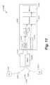
- FIG. 11shows a schematic of an example physiological data collection device.
- FIG. 12shows a schematic of an example physiological data collection device.
- FIG. 1shows an example of a self-assessment kit 100 for obtaining ECG data from a subject.
- the self-assessment kit 100includes a data collection unit 105 , a lead-wire set 110 , electrodes 115 in the form of removable electrode patches, and program code 120 stored on a medium such as a CD-ROM.
- the self-assessment kitallows a subject to obtain his or her own ECG signal, upload ECG data to a remote data processing center, and obtain an assessment from the data processing center without the need to involve a third-party medical practitioner such as a prescribing physician.
- the self-assessment kitcan be configured to allow a subject to self-monitor his or her own ECG signal for a specified period of time such as 14 days.
- the lead-wire set 110has a connector head 125 , a first electrode lead 121 , and a second electrode lead 122 .
- the connector head 125is configured to be connected to the data collection unit 105 . When connected, the data collection unit 105 can be hung from the neck of the subject using a lanyard 124 on the lead-wire set 110 .
- the connector head 125also includes an electrode connector 170 .
- the electrode connector 170is a male end with multiple lead-wire set contacts 171 at a distal end of the electrode connector 170 .
- the electrodes 115are disposable electrode patches that can be connected to distal ends of the first electrode lead 121 and the second electrode lead 122 .
- the electrodes 115have adhesive backing so that they can be stuck to the chest of the subject.
- the self-assessment kit 110can include enough disposable electrodes 115 for the specified period of time.
- the data collection unit 105is connected to the connector head 125 , and one of the electrode patches is connected to the first electrode lead 121 and another of the electrode patches is connected to the second electrode lead 122 .
- a subjectsticks the connected electrodes to his or her chest and wears the data collection unit 105 around his or her neck with the lanyard 124 .
- the data collection unit 105obtains an electrical signal from the electrode patches connected to the first electrode lead 121 and the second electrode lead 122 .
- the electrical signalis converted to a digital signal and stored in the data collection unit 105 as ECG data.
- FIG. 2shows a side perspective view of the data collection unit 105 and the lead-wire set 110 .
- a clip 250 on a side of the connector head 125clips into a clip receptacle 255 on the data collection unit 105 to securely fasten the lead-wire set 110 to the data collection unit 105 .
- the other side of the connector head 125has a similar such clip.
- a usercan depress a thumb tab 256 on the clip 250 to disengage the clip 250 from the clip receptacle 255 .
- FIG. 3shows a front perspective view of a portion of the lead-wire set 110 , including the connector head 125 .
- the connector head 125has a USB connector receptacle 390 adjacent to the electrode connector 170 .
- FIG. 4shows a front perspective view of the data collection unit 105 .
- the data collection unit 105includes a male USB connector 280 and a female electrode connector receptacle 281 adjacent to the USB connector 280 .
- the data collection unit 105has data collection unit contacts 489 inside the electrode connector receptacle 281 .
- the USB connector 280also has standard USB contacts 499 inside the USB connector 280 .
- the electrode connector 170 on the connector head 175is received into electrode connector receptacle 281 on the data collection unit 105 , and the lead-wire set contacts 171 make contact with the data collection unit contacts 489 .
- the USB connector 280is received into the USB connector receptacle 390 on the connector head 125 .
- the USB connector 280cannot simultaneously be connected to an external device such as a personal computer. This helps to protect a subject from simultaneously being connected with a power source for the data collection unit 105 and with another power source in an external device. Accordingly, there is no need to provide the data collection unit 105 with galvanic isolation circuitry to isolate the subject from the power source of an external device connected to the data collection unit 105 while the subject is connected to the data collection unit 105 .
- datacan automatically be obtained from the lead-wire set 110 and stored on the data collection unit 105 .
- the data obtaining and storingcan be terminated automatically.
- FIG. 5shows an example system 500 for uploading the ECG data stored on the data collection unit 105 .
- the program code 120can be run on a computer system 510 such as the subject's personal computer.
- the computer system 510includes a computer and a display device.
- the subjectcan disconnect the data collection unit 105 from the lead-wire set 110 and connect the USB connector 280 to the computer system 510 .
- the program codewhen run by the computer system 510 , supports access to a remote data processing center 520 so that the ECG data can be uploaded from the data collection unit 105 over a network 515 to the remote data processing center 520 where the physiological data is analyzed.
- the program codecan support access to the remote data processing center 520 by automatically initiating a transmission of the ECG data stored on the data collection unit 105 upon detecting that the data collection unit 105 is connected to the computer system 510 .
- the data processing centercan obtain demographic data about the subject.
- Demographic datacan assist in the analysis of the physiological data obtained from the data collection unit. For example, a particular event detected in a physiological signal can be serious for one person and not serious for another based on demographics such as age.
- the program codewhen run by the computer system 510 , can also facilitate the data processing center obtaining demographic data about the subject.
- the data processing center 520includes a computer 530 that analyzes the physiological data for abnormal and/or clinically significant events.
- the computer 530can determine, using predefined algorithms, arrhythmias in the subject's ECG data and can provide a report to a medical professional 540 , such as a medical technician and/or a doctor.
- the medical professionalcan review the reported arrhythmias in the subject's ECG signal from a display device 533 connected the computer 530 and provide feedback via input device 534 to the computer 530 as to which events were accurately identified and which events were inaccurately identified.
- a report of the reviewed arrhythmic eventscan be compiled at the data processing center 520 and provided to the subject.
- the reportcan be provided to the subject over the network 515 .
- the program code 120can include code for a user application that presents the report to the subject from the subject's computer system 510 .
- the program code 120can be stored on a medium such as CD ROM as shown in FIG. 1 .
- the program codecan be stored on a medium on the data collection unit 105 such as non-volatile memory.
- the program codewhen the subject plugs the data collection unit 105 into the subject's computer system 510 , the program code can be run by the subject's computer system 510 to support access to the remote data processing center 520 by automating the process of uploading the ECG from the data collection unit 105 to the data processing center 520 , or by directing the subject to download, from a remote server system, an application for uploading the subject's ECG data.
- the program code stored on the data collection unit 105can also include program code that runs when the subject plugs the data collection unit 105 into the subject's computer system 510 and directs the subject to an external location such as a website for uploading the ECG data on the data collection unit 105 without installing an application on the subject's computer system 510 .
- a subjectcan use the self-assessment kit 100 to self-monitor by plugging the lead-wire set 110 into the data collection unit 105 which in turn powers the data collection unit 105 and lead-wire set 110 and initiates recording of data from the lead-wire set 110 to memory on the data collection unit 105 .
- the subjectcan unplug the lead-wire set from the data collection unit 105 which powers down the data collection unit 110 and lead-wire set and stops recording of data.
- the subjectcan then plug the data collection unit 105 into the computer 510 connected to the network 515 .
- the datacan be automatically uploaded to the remote data processing center 520 .
- the computer 510can include a public terminal such as a kiosk specifically provided for obtaining the subject data from the data collection unit and uploading the subject data to the data processing center 520 .
- the public terminalis provided in a public location such as in a health care facility like a doctor's office, a pharmacy, or the like.
- the public terminalcan be pre-loaded with a program for obtaining the data from the data processing device and uploading the data over the network 515 to the data processing center 520 .
- the public terminalcan also be configured to obtain the demographic information from the subject when the subject uploads the data.
- a report from the data processing center 520can be viewed or printed directly from the public terminal.
- the subjectcan provide the data collection unit 110 to a third-party for uploading the data to the data processing center 520 .
- the self-assessment kitcan include a pre-paid package for mailing the data collection unit 110 to a third-party or directly to the data processing center.
- the kit 100can also include a questionnaire for the subject to fill-out to provide demographic data to facilitated analysis by the data processing center 520 and to provide a location for a report to be sent to the subject either by mail or electronically.
- FIG. 6shows an example process 600 for obtaining physiological data from a subject.
- a physiological data collection deviceis provided to a subject.
- the subjectcan purchase the physiological data collection device as part of a self-assessment kit such as a one-time use self-assessment kit that is preauthorized to allow a subject to self-record his or her ECG signal for a predetermined time period and to receive an analysis service from a data processing center.
- the analysis servicecan include, for example, analysis of the ECG signal for that predetermined time period.
- the kitcan include all the materials necessary for a subject to self-record his or her cardiac activity for the predetermined time period and to obtain a report from a data processing center—including, for example, a data collection unit, electrode leads, sufficient disposable electrodes for the predetermined time period, and program code for allowing the subject to upload data to the data processing center.
- the physiological data collection devicecan also include unused memory just sufficient to store ECG data for the predetermined time period, and a battery with just sufficient power for operating the physiological data collection device for the predetermined time period.
- the physiological data collection deviceis also configured to connect to a computer, such as a subject's personal computer.
- the physiological data collection deviceis powered.
- the physiological data collection devicecan be powered by an internal battery when the subject connects the electrode leads to the data collection unit, as discussed in more detail below in connection with FIGS. 10 and 13 .
- the data acquisition from the electrode leadscan be automatic upon the electrode leads being connected to the physiological data collection device.
- ECG data from the subjectis stored in memory in the physiological data collection device.
- the subjectconnects the physiological data collection device to a computer.
- the subjectcan connect the physiological data collection device to the computer when the data collection is complete, such as when the memory is full, or when the battery dies.
- the subjectconnects the physiological data collection device to the computer using, for example, a USB connector on the physiological data collection device.
- the ECG datacan be uploaded to the data processing center automatically when the physiological data collection device is connected to the computer.
- the computercan run a software application that obtains data from the memory, including ECG data, and transfers the ECG data to the data processing center.
- a software applicationcan be installed on the computer.
- program codecan be stored on the memory of the physiological data collection device that auto-runs when the physiological data collection device is connected to the computer.
- the auto-run program codecan prompt the user to download an application from a remote server for uploading the data from the physiological data collection device.
- the auto-run program codecan direct the subject to a remote application, such as a website, that directs the subject to upload data from the physiological data collection device without installing an application on the computer.
- data from the physiological data collection deviceis obtained by the data processing center.
- the data processing centerverifies, based on the uploaded data, whether the physiological data collection device is pre-authorized for an analysis service. For example, the data processing center can check a unique identifier of the physiological data collection device, such as a serial number, to determine if the physiological data collection device is preauthorized for the analysis service. The data processing center can also check to determine whether an analysis service has already been provided for the physiological data collection device. If the physiological data collection device is not pre-authorized, or if an analysis service has already been provided for the pre-authorized physiological data collection device, the data processing center can indicate as much to the subject and prompt the subject for payment for the analysis service.
- the data processing centeranalyzes the ECG data from the physiological data collection device for arrhythmia events. Predetermined computer algorithms can be used to analyze the ECG data for arrhythmia events.
- the data processing centercan obtain feedback from a medical professional, such as a medical technician and/or a doctor.
- a medical professionalsuch as a medical technician and/or a doctor.
- the identified arrhythmic eventsare provided to a medical professional for further analysis and/or review.
- the medical professionalcan determine the accuracy of the identified events and provide feedback to the data processing center.
- a reportis provided to the subject at 680 .
- the reportis presented to the subject.
- the reportcan be provided to the subject in various ways, such as by mail, by phone, by fax, by email, or by a software application.
- An application on the subject's computercan be configured to obtain the report from the data processing center and to present the report to the subject.
- the applicationcan be a web-based application.
- the subjectcan be notified that his or her report is available. And, the subject can log-on to the web-based application, to view the report.
- the reportcan also contain a recommendation to the subject to consult his or her personal physician based on the results of the report, such as when the analysis identifies clinically significant arrhythmic events.
- Analog signal datais obtained from the lead-wire set 710 over the lead-wire set interface 730 .
- the analog signalis digitized by the A/D converter 725 and stored by the processor in the memory 719 .
- the data collection unit 705can have just sufficient memory 719 for storing the digitized data from a subject obtained over a predefined time period.
- the data collection unitcan have just sufficient memory for the digitized data and for program code necessary for supporting access to a remote data processing center so that the digitized data can be uploaded to the data processing center.
- the data collection unit 705can be plugged into a computer via a data connector 745 .
- the data connector 745can be a USB data connector, a firewire connector, a serial port connector, or the like.
- computer poweris sensed by the processor 717 .
- the processor 717can then transfer the digitized data from the memory 719 to the computer for uploading to a remote data processing center.
- FIGS. 8 a and 8 bshow an example data collection unit 805 .
- the data collection unit 805prevents a subject from connecting an electrode to the data collection unit 805 at the same time the data collection unit 805 is connected to an external device such as the subject's computer.
- the data collection unit 805has a USB connector 880 for connecting to an external computer.
- Data stored on the data collection unit 805such as ECG data, can be uploaded to a computer via the USB connector 880 .
- the USB connector 880When the data collection unit 805 is used to obtain ECG data, the USB connector 880 is rotated 180 degrees so that the USB connector 880 is nestled in a recess 855 in the data collection unit 805 as shown in FIG. 8 b .
- a female electrode connector receptacle 881When the USB connector 880 is nestled in the recess 855 , a female electrode connector receptacle 881 is exposed.
- the electrode connector receptacle 881receives an electrode connector on a lead-wire set (not shown).
- the electrode connectorhas lead-wire set contacts that make contact with data collection unit contacts 889 in the electrode connector receptacle 881 when the lead-wire set is connected to the data collection unit 805 .
- the lead-wire set contactsmake contact with the data collection unit contacts so that ECG data can be obtained from the lead-wire set.
- the USB connector 880cannot be connected to a computer or any other external device because the USB connector 880 is nestled in the recess 855 .
- a USB connector on a data collection unitcan be customized to include data collection unit contacts (in addition to the USB contacts) so that a lead-wire set communicates with the data collection unit through the USB connector by making contact with the data collection unit contacts in the USB connector.
- the USB connectorcan still be used to connect the data collection unit to a computer because it has standard USB contacts.
- FIGS. 9A and 9Bshow an example data collection unit 905 .
- the data collection unit 905has a female electrode connector receptacle 981 .
- Data collection unit contacts 989are located inside the electrode connector receptacle 981 .
- a lead-wire set(not shown) is connected to the data collection unit 905
- an electrode connector on the lead-wire setis received into the electrode connector receptacle 981 on the data collection unit 905
- lead-wire set contacts on the electrode connectormake contact with the data collection unit contacts 989 so that ECG data can be obtained by the data collection unit 905 .
- the ECG datacan be digitized and stored on a removable USB device 948 in the data collection unit 905 .
- the USB device 948is connected to the data collection unit 905 as shown in FIG. 9A .
- the USB deviceis removed from the data collection unit 905 as shown in FIG. 9B .
- This configurationphysically prevents a subject hooked-up to the data collection unit 905 from being electrically connect to an external device via USB device 948 because the USB device 948 must be removed from the data collection unit 905 in order to be connected to a computer.
- FIG. 10shows a schematic of an example physiological data collection device 1000 .
- the physiological data collection device 1000includes a data collection unit 1005 and a lead-wire set 1010 .
- the data collection unit 1005includes a power source 1015 that provides power to an apparatus load 1047 .
- the apparatus loadcan include, for example, processor electronics for obtaining and storing ECG data from the lead-wire set 1010 , such as a processor, an A/D converter, non-volatile memory, etc.
- the data collection unit 1005also includes a lead-wire set interface 1030 .
- the lead-wire set interface 1030has five data collection unit contacts—a first data collection unit contact 1089 a , a second data collection unit contact 1089 b , a third data collection unit contact 1089 c , a fourth data collection unit contact 1089 d , and a fifth data collection unit contact 1089 e.
- the lead-wire set 1010has a lead-wire set connector 1027 , a first and second electrode leads 1021 and 1022 , and electrodes 1011 and 1012 .
- the lead-wire set connector 1027when connected to the data collection unit 1005 , has five lead-wire set contacts—a first lead-wire set contact 1071 a , a second lead-wire set contact 1071 b , a third lead-wire set contact 1071 c , a fourth lead-wire set contact 1071 d , and a fifth lead-wire set contact 1071 e —that make contact with the first data collection unit contact 1089 a , the second data collection unit contact 1089 b , the third data collection unit contact 1089 c , the fourth data collection unit contact 1089 d , and the fifth data collection unit contact 1089 e , respectively.
- Two of the lead-wire set contactsare for the electrode leads 1021 and 1022 , two are for powering the data collection unit 1005 , and one optional the lead wire set contact is for interrupting the processor when the lead-wire set 1010 has been disconnected from the data collection unit 1005 .
- the fourth lead-wire set contact 1071 d and the fifth lead-wire set contact 1071 eare connected to the first electrode lead 1021 and the second electrode lead 1022 .
- an ECG signalcan be obtained by the data collection unit 1005 from the electrodes 1011 and 1012 .
- the first lead-wire set contact 1071 amakes contact with the first data collection unit contact 1089 a .
- contactis broken between the first lead-wire set contact 1071 a and the first data collection unit contact 1089 a , which in turn sends an interrupt signal to the processor in the data collection unit 1005 .
- the interrupt signalstops the processor from recording data to the non-volatile memory before the capacitance in the opened circuit is lost. The interrupt signal helps prevent the non-volatile memory from becoming corrupted.
- other circuitrysuch as a real-time clock
- Thisallows an accurate determination of elapsed time for ECG data obtained by the lead-wire set 1010 .
- the elapsed time from the beginning of recordingcan be stored with the ECG data obtained from the lead-wire set 1010 .
- components not included in the apparatus loadcan be connected to the power source 1015 separately, but in response to the lead-wire set 1010 being disconnected from the data collection unit 1005 , those components can be placed into a standby mode—powered down to a lower operational state to conserve power.
- FIG. 11shows a schematic of an example physiological data collection device 1100 .
- the physiological data collection device 1100has a data collection unit 1105 and a lead-wire set 1110 .
- the lead-wire setincludes a lead-wire set connector 1127 for connecting the lead-wire set 1110 to the data collection unit 1105 .
- the lead-wire set 1110includes electrodes 1111 and 1112 which are connected to electrode leads 1121 and 1122 .
- the electrode leads 1121 and 1122are connected to a lead-wire set connector 1127 which in turn can be physically connected to the data collection unit 1105 via a lead-wire set interface 1130 .
- the lead-wire setalso includes a battery 1116 in the lead-wire set connector 1127 that powers the physiological data collection device 1100 , including processor electronics in the data collection unit 1105 such as a processor 1117 , memory 1119 (e.g. non-volatile memory), and an analog-to-digital (“A/D”) converter 1125 .
- the battery 1116can be large enough to run the physiological data collection device 1100 for a predefined time period. For example, the battery can be large enough to run the physiological data collection device 1100 for a long enough period of time to fill the memory 1119 with data obtained from the lead-wire set 1110 . When the battery dies after the predefined time period, it can be disposed of with the disposal of the lead-wire set 1110 .
- the data collection unit 1105can be reused for another predefined time period, upon the connection of another lead-wire set with a fresh battery.
- the lead-wire set 1110can be interchanged with another interchangeable lead-wire set with a new battery so that data collection can continue.
- the batterycan be removable; when the removable battery dies, the removable battery can be replaced.
- Analog signal datais obtained from the lead-wire set 1110 over the lead-wire set interface 1130 .
- the analog signalis digitized by the A/D converter 1125 and stored by the processor 1117 in the memory 1119 .
- the data collection unit 1105can have just sufficient memory 1119 for storing the digitized data from a subject obtained over a predefined time period.
- the data collection unit 1105can have just sufficient memory for the digitized data and for program code necessary for supporting access to a remote data processing center so that the digitized data can be uploaded to the data processing center.
- the data collection unit 1105can be plugged into a computer via a data connector 1145 .
- the data connector 1145can be a USB data connector, a firewire connector, a serial port connector, or the like.
- computer poweris sensed by the processor 1117 .
- the processor 1117can then transfer the digitized data from the memory 1119 to the computer for uploading to a remote data processing center.
- FIG. 12shows a schematic of an example physiological data collection device 1200 .
- the physiological data collection device 1200includes a data collection unit 1205 and lead-wire set 1210 .
- the lead-wire set 1210includes a power source 1215 that provides power to an apparatus load 1247 when the lead-wire set 1210 is connected to the data collection unit 1205 .
- the apparatus loadcan include, for example, processor electronics for obtaining and storing ECG data from the lead-wire set 1210 , such as a processor, an A/D converter, non-volatile memory, etc.
- the data collection unit 1205also includes a lead-wire set interface 1230 .
- the lead-wire set interface 1230has five data collection unit contacts—a first data collection unit contact 1289 a , a second data collection unit contact 1289 b , a third data collection unit contact 1289 c , a fourth data collection unit contact 1289 d , and a fifth data collection unit contact 1289 e.
- the lead-wire set 1210has a lead-wire set connector 1227 , a first and second electrode leads 1221 and 1222 , and electrodes 1211 and 1212 .
- the lead-wire set connector 1227when connected to the data collection unit 1205 , has five lead-wire set contacts—a first lead-wire set contact 1271 a , a second lead-wire set contact 1271 b , a third lead-wire set contact 1271 c , a fourth lead-wire set contact 1271 d , and a fifth lead-wire set contact 1271 e —that make contact with the first data collection unit contact 1289 a , the second data collection unit contact 1289 b , the third data collection unit contact 1289 c , the fourth data collection unit contact 1289 d , and the fifth data collection unit contact 1289 e , respectively.
- Two of the lead-wire set contactsare for the electrode leads 1221 and 1221 , two are for powering the data collection unit 1205 , and one optional lead-wire set contacts is for interrupting the processor when the lead-wire set 1210 has been disconnected from the data collection unit 1205 .
- the fourth lead-wire set contact 1271 d and the fifth lead-wire set contact 1271 eare connected to the first electrode lead 1221 and the second electrode lead 1222 .
- an ECG signalcan be obtained by the data collection unit 1205 from the electrodes 1211 and 1212 .
- the second lead-wire set contact 1271 bmakes contact with the second data collection unit contact 1289 b
- the third lead-wire set contact 1271 cmakes contact with the third data collection unit contact 1289 c
- the second and third lead-wire set contacts 1271 b and 1271 cclose an open circuit in the data collection unit 1205 when the lead-wire set connector is connected to the data collection unit 1205 , allowing power to be supplied from the power source 1215 in the lead-wire set 1215 so that the subject's ECG data can be obtained. This allows the data collection unit 1205 to operate as soon as the lead-wire set 1210 is connected. This also prevents power leakage when the lead-wire set 1210 is disconnected.
- the first lead-wire set contact 1271 amakes contact with the first data collection unit contact 1289 a .
- contactis broken between the first lead-wire set contact 1271 a and the first data collection unit contact 1289 a , which in turn sends an interrupt signal to the processor in the data collection unit 1205 .
- the interrupt signalstops the processor from recording data to the non-volatile memory before the capacitance in the opened circuit is lost. The interrupt signal helps prevent the non-volatile memory from becoming corrupted.
- FIG. 13shows an example process 1300 for powering a physiological data collection unit.
- a subject interfaceis connected to a data collection unit.
- the data collection unitis powered on.
- the subject interfacecan power on the data collection unit by closing an open circuit between an apparatus load and a power supply.
- the power supplycan include the power needed to run processing electronics for obtaining ECG data from a subject.
- the power supplycan be located in the data collection unit. In some examples, the power supply can be located in the subject interface.
- physiological datais obtained and stored by the data collection unit. The physiological data can be obtained automatically when the subject interface is connected to the data collection unit.
- the subjectneeds only connect the subject interface to the data collection unit to power the data collection unit and to start the data collection unit obtaining and storing data.
- the subject interfaceis disconnected.
- the data collection unitpowers off.
- Disconnecting the subject interfacecan power off the data collection unit by creating an open circuit between the apparatus load and the power supply.
- the process 1300can optionally send an interrupt signal to a processor in the data collection unit when the subject interface is disconnected to interrupt storing data to memory in order to prevent the memory from being corrupted. Also, disconnecting the data collection unit stops the obtaining and recording of data from the subject interface.
- the disclosed systems, techniques, and all of the functional operations described and illustrated in this specificationcan be implemented in digital electronic circuitry, or in computer hardware, firmware, software, or in combinations of the forgoing.
- one or more computers and/or circuitrycan be operable to or configured and arranged to perform the functions and techniques disclosed herein.
- Apparatuses and/or systemscan be implemented using a software product (e.g., a computer program code) tangibly embodied in a machine-readable storage device for execution by a programmable processor, and processing operations can be performed by a programmable processor executing a program of instructions to perform functions by operating on input data and generating output.
- the systemcan be implemented advantageously in one or more software programs that are executable on a programmable system.
- This programmable systemcan include the following: 1) at least one programmable processor coupled to receive data and instructions from, and to transmit data and instructions to, a data storage system; 2) at least one input device; and 3) at least one output device.
- each software programcan be implemented in a high-level procedural or object-oriented programming language, or in assembly or machine language if desired; and in any case, the language can be a compiled or an interpreted language.
- suitable processorsinclude, by way of example, both general and special purpose microprocessors.
- a processorwill receive instructions and data from a read-only memory, a random access memory, and/or a machine-readable signal (e.g., a digital signal received through a network connection).
- the essential elements of a computerare a processor for performing instructions and one or more memory devices for storing instructions and data.
- a computerwill include one or more mass storage devices for storing data files. Such devices can include magnetic disks, such as internal hard disks and removable disks, magneto-optical disks, and optical disks.
- Storage devices suitable for tangibly embodying software program instructions and datainclude all forms of non-volatile memory, including, by way of example, the following: 1) semiconductor memory devices, such as EPROM (electrically programmable read-only memory); EEPROM (electrically erasable programmable read-only memory) and flash memory devices; 2) magnetic disks such as internal hard disks and removable disks; 3) magneto-optical disks; and 4) CD-ROM disks. Any of the foregoing can be supplemented by, or incorporated in, ASICs (application-specific integrated circuits).
- ASICsapplication-specific integrated circuits
- a communications networksuch as a wired or wireless network.
- Examples of communication networksinclude, e.g., a local area network (“LAN”), a wide area network (“WAN”), the Internet or any combinations of such.
- systemscan be implemented on a computer system having a display device such as a monitor or LCD (liquid crystal display) screen for displaying information to the user and a keyboard and a pointing device such as a mouse or a trackball by which the user can provide input to the computer system.
- the computer systemcan be programmed to provide a graphical user interface through which computer programs interact with users.
Landscapes
- Engineering & Computer Science (AREA)
- Health & Medical Sciences (AREA)
- Life Sciences & Earth Sciences (AREA)
- Public Health (AREA)
- General Health & Medical Sciences (AREA)
- Medical Informatics (AREA)
- Biomedical Technology (AREA)
- Physics & Mathematics (AREA)
- Theoretical Computer Science (AREA)
- Biophysics (AREA)
- Surgery (AREA)
- General Engineering & Computer Science (AREA)
- Epidemiology (AREA)
- Primary Health Care (AREA)
- Pathology (AREA)
- Molecular Biology (AREA)
- Animal Behavior & Ethology (AREA)
- Heart & Thoracic Surgery (AREA)
- Veterinary Medicine (AREA)
- General Physics & Mathematics (AREA)
- General Business, Economics & Management (AREA)
- Business, Economics & Management (AREA)
- Human Computer Interaction (AREA)
- Physiology (AREA)
- Computer Hardware Design (AREA)
- Computer Networks & Wireless Communication (AREA)
- Physical Education & Sports Medicine (AREA)
- Cardiology (AREA)
- Microelectronics & Electronic Packaging (AREA)
- Computer Security & Cryptography (AREA)
- Nuclear Medicine, Radiotherapy & Molecular Imaging (AREA)
- Urology & Nephrology (AREA)
- Measurement And Recording Of Electrical Phenomena And Electrical Characteristics Of The Living Body (AREA)
Abstract
Description
Claims (15)
Priority Applications (4)
| Application Number | Priority Date | Filing Date | Title |
|---|---|---|---|
| US13/287,949US8909832B2 (en) | 2010-11-02 | 2011-11-02 | Medical data collection apparatus |
| US14/547,895US20150081959A1 (en) | 2010-11-02 | 2014-11-19 | Medical data collection apparatus |
| US15/339,571US11331031B2 (en) | 2010-11-02 | 2016-10-31 | Medical data collection apparatus |
| US15/339,564US20170042423A1 (en) | 2010-11-02 | 2016-10-31 | Medical data collection apparatus |
Applications Claiming Priority (2)
| Application Number | Priority Date | Filing Date | Title |
|---|---|---|---|
| US40952110P | 2010-11-02 | 2010-11-02 | |
| US13/287,949US8909832B2 (en) | 2010-11-02 | 2011-11-02 | Medical data collection apparatus |
Related Child Applications (1)
| Application Number | Title | Priority Date | Filing Date |
|---|---|---|---|
| US14/547,895ContinuationUS20150081959A1 (en) | 2010-11-02 | 2014-11-19 | Medical data collection apparatus |
Publications (2)
| Publication Number | Publication Date |
|---|---|
| US20120110228A1 US20120110228A1 (en) | 2012-05-03 |
| US8909832B2true US8909832B2 (en) | 2014-12-09 |
Family
ID=45997933
Family Applications (8)
| Application Number | Title | Priority Date | Filing Date |
|---|---|---|---|
| US13/287,949Active2032-12-04US8909832B2 (en) | 2010-11-02 | 2011-11-02 | Medical data collection apparatus |
| US13/287,968ActiveUS9021161B2 (en) | 2010-11-02 | 2011-11-02 | System and method for electro-cardiogram (ECG) medical data collection wherein physiological data collected and stored may be uploaded to a remote service center |
| US14/547,895AbandonedUS20150081959A1 (en) | 2010-11-02 | 2014-11-19 | Medical data collection apparatus |
| US14/688,891ActiveUS9907481B2 (en) | 2010-11-02 | 2015-04-16 | System and method for electro-cardiogram (ECG) medical data collection wherein physiological data collected and stored may be uploaded to a remote service center |
| US15/339,571Active2034-07-10US11331031B2 (en) | 2010-11-02 | 2016-10-31 | Medical data collection apparatus |
| US15/339,564AbandonedUS20170042423A1 (en) | 2010-11-02 | 2016-10-31 | Medical data collection apparatus |
| US15/339,442ActiveUS10034617B2 (en) | 2010-11-02 | 2016-10-31 | System and method for electro-cardiogram (ECG) medical data collection wherein physiological data collected and stored may be uploaded to a remote service center |
| US16/032,367AbandonedUS20190175048A1 (en) | 2010-11-02 | 2018-07-11 | System and method for electro-cardiogram (ecg) medical data collection wherein physiological data collected and stored may be uploaded to a remote service center |
Family Applications After (7)
| Application Number | Title | Priority Date | Filing Date |
|---|---|---|---|
| US13/287,968ActiveUS9021161B2 (en) | 2010-11-02 | 2011-11-02 | System and method for electro-cardiogram (ECG) medical data collection wherein physiological data collected and stored may be uploaded to a remote service center |
| US14/547,895AbandonedUS20150081959A1 (en) | 2010-11-02 | 2014-11-19 | Medical data collection apparatus |
| US14/688,891ActiveUS9907481B2 (en) | 2010-11-02 | 2015-04-16 | System and method for electro-cardiogram (ECG) medical data collection wherein physiological data collected and stored may be uploaded to a remote service center |
| US15/339,571Active2034-07-10US11331031B2 (en) | 2010-11-02 | 2016-10-31 | Medical data collection apparatus |
| US15/339,564AbandonedUS20170042423A1 (en) | 2010-11-02 | 2016-10-31 | Medical data collection apparatus |
| US15/339,442ActiveUS10034617B2 (en) | 2010-11-02 | 2016-10-31 | System and method for electro-cardiogram (ECG) medical data collection wherein physiological data collected and stored may be uploaded to a remote service center |
| US16/032,367AbandonedUS20190175048A1 (en) | 2010-11-02 | 2018-07-11 | System and method for electro-cardiogram (ecg) medical data collection wherein physiological data collected and stored may be uploaded to a remote service center |
Country Status (3)
| Country | Link |
|---|---|
| US (8) | US8909832B2 (en) |
| EP (2) | EP2635179B1 (en) |
| WO (2) | WO2012061518A1 (en) |
Cited By (11)
| Publication number | Priority date | Publication date | Assignee | Title |
|---|---|---|---|---|
| US20120110226A1 (en)* | 2010-11-02 | 2012-05-03 | Cardionet, Inc. | Medical data collection apparatus |
| US9226679B2 (en) | 2010-05-21 | 2016-01-05 | Medicomp, Inc. | Systems and methods for interelectrode distance optimization in a retractable multi-use cardiac monitor |
| US9451975B2 (en) | 2013-04-08 | 2016-09-27 | Irhythm Technologies, Inc. | Skin abrader |
| US9585584B2 (en) | 2010-05-21 | 2017-03-07 | Medicomp, Inc. | Physiological signal monitor with retractable wires |
| US9597004B2 (en) | 2014-10-31 | 2017-03-21 | Irhythm Technologies, Inc. | Wearable monitor |
| US10271754B2 (en) | 2013-01-24 | 2019-04-30 | Irhythm Technologies, Inc. | Physiological monitoring device |
| US10405799B2 (en) | 2010-05-12 | 2019-09-10 | Irhythm Technologies, Inc. | Device features and design elements for long-term adhesion |
| US11083371B1 (en) | 2020-02-12 | 2021-08-10 | Irhythm Technologies, Inc. | Methods and systems for processing data via an executable file on a monitor to reduce the dimensionality of the data and encrypting the data being transmitted over the wireless network |
| US11246523B1 (en) | 2020-08-06 | 2022-02-15 | Irhythm Technologies, Inc. | Wearable device with conductive traces and insulator |
| US11350865B2 (en) | 2020-08-06 | 2022-06-07 | Irhythm Technologies, Inc. | Wearable device with bridge portion |
| USD1063079S1 (en) | 2021-08-06 | 2025-02-18 | Irhythm Technologies, Inc. | Physiological monitoring device |
Families Citing this family (30)
| Publication number | Priority date | Publication date | Assignee | Title |
|---|---|---|---|---|
| US8301236B2 (en) | 2009-05-22 | 2012-10-30 | Biomedical Systems Corporation | System and method for high resolution wireless full disclosure ECG episode monitoring and analysis |
| US10244949B2 (en) | 2012-10-07 | 2019-04-02 | Rhythm Diagnostic Systems, Inc. | Health monitoring systems and methods |
| US10610159B2 (en) | 2012-10-07 | 2020-04-07 | Rhythm Diagnostic Systems, Inc. | Health monitoring systems and methods |
| US10413251B2 (en) | 2012-10-07 | 2019-09-17 | Rhythm Diagnostic Systems, Inc. | Wearable cardiac monitor |
| USD850626S1 (en) | 2013-03-15 | 2019-06-04 | Rhythm Diagnostic Systems, Inc. | Health monitoring apparatuses |
| US9675267B2 (en) | 2012-10-31 | 2017-06-13 | Firstbeat Technologies Oy | Device for physiological measurement |
| US20140236027A1 (en)* | 2013-02-20 | 2014-08-21 | Perminova Inc. | Necklace-shaped physiological monitor |
| USD921204S1 (en) | 2013-03-15 | 2021-06-01 | Rds | Health monitoring apparatus |
| USD738827S1 (en)* | 2013-04-10 | 2015-09-15 | BBPOS Limited | Lanyard holder with removable USB cable connector |
| JP2016531663A (en) | 2013-08-01 | 2016-10-13 | ゾール メディカル コーポレイションZOLL Medical Corporation | System and method for utilizing an identification device in a wearable medical treatment device |
| ES2828723T3 (en)* | 2015-02-27 | 2021-05-27 | Icentia Inc | Wearable Physiological Data Acquisition Device and Methods of Using It |
| USD770170S1 (en)* | 2015-06-15 | 2016-11-01 | Apple Inc. | Lanyard |
| USD773056S1 (en) | 2015-10-07 | 2016-11-29 | Braemar Manufacturing, Llc | Wearable medical data collection apparatus for collecting ECG data |
| US11672464B2 (en) | 2015-10-27 | 2023-06-13 | Cardiologs Technologies Sas | Electrocardiogram processing system for delineation and classification |
| US10426364B2 (en) | 2015-10-27 | 2019-10-01 | Cardiologs Technologies Sas | Automatic method to delineate or categorize an electrocardiogram |
| US10827938B2 (en) | 2018-03-30 | 2020-11-10 | Cardiologs Technologies Sas | Systems and methods for digitizing electrocardiograms |
| US10779744B2 (en) | 2015-10-27 | 2020-09-22 | Cardiologs Technologies Sas | Automatic method to delineate or categorize an electrocardiogram |
| US11331034B2 (en) | 2015-10-27 | 2022-05-17 | Cardiologs Technologies Sas | Automatic method to delineate or categorize an electrocardiogram |
| US11224373B2 (en)* | 2016-08-17 | 2022-01-18 | Koninklijke Philips N.V. | Adapter and connection unit for coupling with medical coupling unit and sensor |
| CN106923821A (en)* | 2016-12-20 | 2017-07-07 | 常州市善松信息科技有限公司 | A kind of electrocardiogram (ECG) data storage method of multi-lead switching at runtime |
| JP2020531225A (en) | 2017-08-25 | 2020-11-05 | カーディオログス テクノロジーズ エスアーエス | User interface for electrocardiogram analysis |
| CN108378924A (en)* | 2017-11-16 | 2018-08-10 | 任伟 | A kind of electrocardiogram machine lead wire storage box |
| JP7009955B2 (en)* | 2017-11-24 | 2022-01-26 | トヨタ自動車株式会社 | Medical data communication equipment, servers, medical data communication methods and medical data communication programs |
| JP7013817B2 (en)* | 2017-11-24 | 2022-02-01 | トヨタ自動車株式会社 | Medical information systems, medical devices, data communication methods, and programs |
| JP7120868B2 (en)* | 2018-09-28 | 2022-08-17 | フクダ電子株式会社 | medical electronics |
| JP7166125B2 (en)* | 2018-09-28 | 2022-11-07 | フクダ電子株式会社 | medical electronics |
| CN113631097A (en) | 2019-01-25 | 2021-11-09 | Rds公司 | Health monitoring system and method |
| US12016694B2 (en) | 2019-02-04 | 2024-06-25 | Cardiologs Technologies Sas | Electrocardiogram processing system for delineation and classification |
| EP4021293A4 (en) | 2019-08-28 | 2023-08-09 | Rds | Vital signs or health monitoring systems and methods |
| US11678831B2 (en) | 2020-08-10 | 2023-06-20 | Cardiologs Technologies Sas | Electrocardiogram processing system for detecting and/or predicting cardiac events |
Citations (29)
| Publication number | Priority date | Publication date | Assignee | Title |
|---|---|---|---|---|
| US5678562A (en) | 1995-11-09 | 1997-10-21 | Burdick, Inc. | Ambulatory physiological monitor with removable disk cartridge and wireless modem |
| US6117077A (en) | 1999-01-22 | 2000-09-12 | Del Mar Medical Systems, Llc | Long-term, ambulatory physiological recorder |
| US6223080B1 (en) | 1998-04-29 | 2001-04-24 | Medtronic, Inc. | Power consumption reduction in medical devices employing multiple digital signal processors and different supply voltages |
| US20030028442A1 (en) | 2001-08-06 | 2003-02-06 | Craig Wagstaff | Method of supplying heart screening services directly to a customer |
| US20040229478A1 (en) | 2003-05-13 | 2004-11-18 | Chen Chao Ming | Rotatory wireless USB network interface card |
| US20050251055A1 (en) | 2004-05-10 | 2005-11-10 | Medpond, Llc | Method and apparatus for detecting physiologic signals |
| US20050251003A1 (en) | 2001-07-17 | 2005-11-10 | Gmp/Wireless Medicine, Inc. | Disposable chest assembly |
| US6976958B2 (en) | 2000-12-15 | 2005-12-20 | Q-Tec Systems Llc | Method and apparatus for health and disease management combining patient data monitoring with wireless internet connectivity |
| US20060100530A1 (en) | 2000-11-28 | 2006-05-11 | Allez Physionix Limited | Systems and methods for non-invasive detection and monitoring of cardiac and blood parameters |
| US20060149594A1 (en) | 2004-12-30 | 2006-07-06 | Healthcard Network | Health care facility admission control system |
| US20070167694A1 (en) | 2005-12-21 | 2007-07-19 | Everest Biomedical Instruments Co. | Integrated Portable Anesthesia and Sedation Monitoring Apparatus |
| US20070197878A1 (en) | 2004-07-09 | 2007-08-23 | Dror Shklarski | Wearable device, system and method for monitoring physiological and/or environmental parameters |
| US7361188B2 (en) | 2005-04-08 | 2008-04-22 | Exelys, Llc | Portable cardiac monitor |
| US20080218799A1 (en) | 2003-12-02 | 2008-09-11 | Super Talent Electronics, Inc. | Extended COB-USB With Dual-Personality Contacts |
| US20080234592A1 (en) | 2006-09-23 | 2008-09-25 | Meng Huat Damian Lim | Method and apparatus for generating an electrocardiogram |
| US20080243020A1 (en) | 2005-10-08 | 2008-10-02 | Chang-An Chou | Physiological Signal Collecting And Monitoring Device And System |
| EP2030565A1 (en)* | 2007-09-02 | 2009-03-04 | Medicalgorithmics Sp. Z.O.O. | Systems for safe and remote outpatient ECG monitoring |
| US7598878B2 (en) | 2001-12-10 | 2009-10-06 | Rami Goldreich | Method and device for measuring physiological parameters at the wrist |
| US7615007B2 (en) | 2006-10-04 | 2009-11-10 | Dexcom, Inc. | Analyte sensor |
| US20090326612A1 (en) | 2008-06-26 | 2009-12-31 | Michael J. Distler | Electronic biofeedback stimulation device |
| US20100004522A1 (en) | 2008-07-02 | 2010-01-07 | Eddie Varela | Continuously Wearable Compact Blood Glucose Measuring Device |
| US20100099954A1 (en) | 2008-10-22 | 2010-04-22 | Zeo, Inc. | Data-driven sleep coaching system |
| US7794406B2 (en) | 2004-11-22 | 2010-09-14 | Widemed Ltd. | Detection of cardiac arrhythmias using a photoplethysmograph |
| US20100268103A1 (en) | 2009-04-16 | 2010-10-21 | Cardionet, Inc. | Cardiac Arrhythmia Report |
| US20110112413A1 (en) | 2009-11-06 | 2011-05-12 | Newcardio, Inc | Method for automated ekg analysis |
| US20110160553A1 (en) | 2009-12-31 | 2011-06-30 | Medtronic Minimed, Inc. | Sensor and monitor system |
| US8082027B2 (en)* | 2010-05-07 | 2011-12-20 | General Electric Company | Portable USB electrocardiograph system and method |
| US8144948B2 (en) | 2007-03-30 | 2012-03-27 | Sony Corporation | Method and apparatus for transporting images |
| US20120108934A1 (en) | 2010-10-27 | 2012-05-03 | Dexcom, Inc. | Continuous analyte monitor data recording device operable in a blinded mode |
Family Cites Families (35)
| Publication number | Priority date | Publication date | Assignee | Title |
|---|---|---|---|---|
| GB1424564A (en)* | 1972-06-30 | 1976-02-11 | Olympus Optical Co | Recording and reproducing a bioelectrical signal |
| JPH06197875A (en)* | 1992-11-05 | 1994-07-19 | Yokogawa Electric Corp | Holter cardiograph |
| US5462051A (en) | 1994-08-31 | 1995-10-31 | Colin Corporation | Medical communication system |
| US5596318A (en)* | 1995-01-12 | 1997-01-21 | Microsoft Corporation | Method for operating a two-way messaging system to extend battery life |
| US6962566B2 (en)* | 2001-04-19 | 2005-11-08 | Sonosite, Inc. | Medical diagnostic ultrasound instrument with ECG module, authorization mechanism and methods of use |
| JP4089030B2 (en) | 1998-09-18 | 2008-05-21 | ソニー株式会社 | Clock generation circuit |
| US7021971B2 (en)* | 2003-09-11 | 2006-04-04 | Super Talent Electronics, Inc. | Dual-personality extended-USB plug and receptacle with PCI-Express or Serial-At-Attachment extensions |
| US6970737B1 (en)* | 2000-09-13 | 2005-11-29 | Ge Medical Systems Information Technologies, Inc. | Portable ECG device with wireless communication interface to remotely monitor patients and method of use |
| US6597943B2 (en)* | 2000-12-26 | 2003-07-22 | Ge Medical Systems Information Technologies, Inc. | Method of using spectral measures to distinguish among atrialfibrillation, atrial-flutter and other cardiac rhythms |
| US6907283B2 (en)* | 2001-03-02 | 2005-06-14 | Ge Medical Systems Information Technologies, Inc. | Patient telemetry device with auto-compensation for impedance changes in leadset antenna |
| US6564090B2 (en)* | 2001-10-11 | 2003-05-13 | Ge Medical Systems Information Technologies, Inc. | Method and apparatus for the serial comparison of electrocardiograms |
| US6752305B2 (en)* | 2002-03-22 | 2004-06-22 | John Shattuck | Identification holder system |
| JP3802476B2 (en) | 2002-10-31 | 2006-07-26 | 三洋電機株式会社 | Portable electrocardiograph |
| US8626262B2 (en) | 2003-10-30 | 2014-01-07 | Halthion Medical Technologies, Inc. | Physiological data collection system |
| JP4239836B2 (en)* | 2004-01-30 | 2009-03-18 | オムロンヘルスケア株式会社 | Biological information measuring device |
| CN100471445C (en)* | 2005-08-01 | 2009-03-25 | 周常安 | Patch type physiological monitoring device |
| US7650007B2 (en)* | 2005-08-24 | 2010-01-19 | Apple Inc. | Lanyard for handheld electronic device |
| US20070142738A1 (en)* | 2005-12-16 | 2007-06-21 | Chin-Yeh Hung | Dynamic heart rate monitor |
| US20070265541A1 (en)* | 2006-05-15 | 2007-11-15 | Chin-Yeh Hung | MP3 player capable of transmitting pulse data |
| ITMO20070194A1 (en)* | 2007-06-07 | 2008-12-08 | Milano Politecnico | PORTABLE ELECTROCARDIOGRAPHIC APPARATUS |
| US20090018456A1 (en)* | 2007-07-11 | 2009-01-15 | Chin-Yeh Hung | Display storage apparatus capable of detecting a pulse |
| US7555588B2 (en) | 2007-08-17 | 2009-06-30 | I/O Interconnect Inc | Computers having USB buses, methods of operation thereof and programs and information for use therewith |
| US8370549B2 (en) | 2007-09-07 | 2013-02-05 | Nike, Inc. | Wearable device assembly having athletic functionality |
| JP2009082364A (en)* | 2007-09-28 | 2009-04-23 | Omron Healthcare Co Ltd | Portable electrocardiograph |
| US8185623B2 (en)* | 2008-02-29 | 2012-05-22 | Physio-Control, Inc. | Selectively routing patient data between field devices and treatment center destinations |
| TWM352354U (en)* | 2008-09-09 | 2009-03-11 | North Vision Tech Inc | Portable electrocardiography monitoring device |
| WO2010103164A1 (en)* | 2009-03-13 | 2010-09-16 | Polar Electro Oy | Data transfer |
| KR20110004660A (en)* | 2009-07-08 | 2011-01-14 | 한국전자통신연구원 | Biological signal measuring device |
| WO2011050283A2 (en)* | 2009-10-22 | 2011-04-28 | Corventis, Inc. | Remote detection and monitoring of functional chronotropic incompetence |
| EP2383859A1 (en)* | 2010-04-28 | 2011-11-02 | Fabio Brucchi | Fast rechargeable electric system for stand-alone power sources |
| US9028404B2 (en)* | 2010-07-28 | 2015-05-12 | Foster-Miller, Inc. | Physiological status monitoring system |
| US8909832B2 (en)* | 2010-11-02 | 2014-12-09 | Braemar Manufacturing, Llc | Medical data collection apparatus |
| US8782308B2 (en) | 2012-02-29 | 2014-07-15 | Cardionet, Inc. | Connector interface system for data acquisition |
| US8787119B2 (en)* | 2012-06-11 | 2014-07-22 | Yeoshua Sorias | Watch assembly with a spare battery for readily powering an external mobile electronic device |
| WO2016081765A1 (en) | 2014-11-19 | 2016-05-26 | Nike Innovate C.V. | Athletic band with removable module |
- 2011
- 2011-11-02USUS13/287,949patent/US8909832B2/enactiveActive
- 2011-11-02WOPCT/US2011/058998patent/WO2012061518A1/enactiveApplication Filing
- 2011-11-02EPEP11838752.1Apatent/EP2635179B1/ennot_activeNot-in-force
- 2011-11-02EPEP11838757.0Apatent/EP2635180B1/ennot_activeNot-in-force
- 2011-11-02USUS13/287,968patent/US9021161B2/enactiveActive
- 2011-11-02WOPCT/US2011/058976patent/WO2012061509A1/enactiveApplication Filing
- 2014
- 2014-11-19USUS14/547,895patent/US20150081959A1/ennot_activeAbandoned
- 2015
- 2015-04-16USUS14/688,891patent/US9907481B2/enactiveActive
- 2016
- 2016-10-31USUS15/339,571patent/US11331031B2/enactiveActive
- 2016-10-31USUS15/339,564patent/US20170042423A1/ennot_activeAbandoned
- 2016-10-31USUS15/339,442patent/US10034617B2/enactiveActive
- 2018
- 2018-07-11USUS16/032,367patent/US20190175048A1/ennot_activeAbandoned
Patent Citations (29)
| Publication number | Priority date | Publication date | Assignee | Title |
|---|---|---|---|---|
| US5678562A (en) | 1995-11-09 | 1997-10-21 | Burdick, Inc. | Ambulatory physiological monitor with removable disk cartridge and wireless modem |
| US6223080B1 (en) | 1998-04-29 | 2001-04-24 | Medtronic, Inc. | Power consumption reduction in medical devices employing multiple digital signal processors and different supply voltages |
| US6117077A (en) | 1999-01-22 | 2000-09-12 | Del Mar Medical Systems, Llc | Long-term, ambulatory physiological recorder |
| US20060100530A1 (en) | 2000-11-28 | 2006-05-11 | Allez Physionix Limited | Systems and methods for non-invasive detection and monitoring of cardiac and blood parameters |
| US6976958B2 (en) | 2000-12-15 | 2005-12-20 | Q-Tec Systems Llc | Method and apparatus for health and disease management combining patient data monitoring with wireless internet connectivity |
| US20050251003A1 (en) | 2001-07-17 | 2005-11-10 | Gmp/Wireless Medicine, Inc. | Disposable chest assembly |
| US20030028442A1 (en) | 2001-08-06 | 2003-02-06 | Craig Wagstaff | Method of supplying heart screening services directly to a customer |
| US7598878B2 (en) | 2001-12-10 | 2009-10-06 | Rami Goldreich | Method and device for measuring physiological parameters at the wrist |
| US20040229478A1 (en) | 2003-05-13 | 2004-11-18 | Chen Chao Ming | Rotatory wireless USB network interface card |
| US20080218799A1 (en) | 2003-12-02 | 2008-09-11 | Super Talent Electronics, Inc. | Extended COB-USB With Dual-Personality Contacts |
| US20050251055A1 (en) | 2004-05-10 | 2005-11-10 | Medpond, Llc | Method and apparatus for detecting physiologic signals |
| US20070197878A1 (en) | 2004-07-09 | 2007-08-23 | Dror Shklarski | Wearable device, system and method for monitoring physiological and/or environmental parameters |
| US7794406B2 (en) | 2004-11-22 | 2010-09-14 | Widemed Ltd. | Detection of cardiac arrhythmias using a photoplethysmograph |
| US20060149594A1 (en) | 2004-12-30 | 2006-07-06 | Healthcard Network | Health care facility admission control system |
| US7361188B2 (en) | 2005-04-08 | 2008-04-22 | Exelys, Llc | Portable cardiac monitor |
| US20080243020A1 (en) | 2005-10-08 | 2008-10-02 | Chang-An Chou | Physiological Signal Collecting And Monitoring Device And System |
| US20070167694A1 (en) | 2005-12-21 | 2007-07-19 | Everest Biomedical Instruments Co. | Integrated Portable Anesthesia and Sedation Monitoring Apparatus |
| US20080234592A1 (en) | 2006-09-23 | 2008-09-25 | Meng Huat Damian Lim | Method and apparatus for generating an electrocardiogram |
| US7615007B2 (en) | 2006-10-04 | 2009-11-10 | Dexcom, Inc. | Analyte sensor |
| US8144948B2 (en) | 2007-03-30 | 2012-03-27 | Sony Corporation | Method and apparatus for transporting images |
| EP2030565A1 (en)* | 2007-09-02 | 2009-03-04 | Medicalgorithmics Sp. Z.O.O. | Systems for safe and remote outpatient ECG monitoring |
| US20090326612A1 (en) | 2008-06-26 | 2009-12-31 | Michael J. Distler | Electronic biofeedback stimulation device |
| US20100004522A1 (en) | 2008-07-02 | 2010-01-07 | Eddie Varela | Continuously Wearable Compact Blood Glucose Measuring Device |
| US20100099954A1 (en) | 2008-10-22 | 2010-04-22 | Zeo, Inc. | Data-driven sleep coaching system |
| US20100268103A1 (en) | 2009-04-16 | 2010-10-21 | Cardionet, Inc. | Cardiac Arrhythmia Report |
| US20110112413A1 (en) | 2009-11-06 | 2011-05-12 | Newcardio, Inc | Method for automated ekg analysis |
| US20110160553A1 (en) | 2009-12-31 | 2011-06-30 | Medtronic Minimed, Inc. | Sensor and monitor system |
| US8082027B2 (en)* | 2010-05-07 | 2011-12-20 | General Electric Company | Portable USB electrocardiograph system and method |
| US20120108934A1 (en) | 2010-10-27 | 2012-05-03 | Dexcom, Inc. | Continuous analyte monitor data recording device operable in a blinded mode |
Non-Patent Citations (2)
| Title |
|---|
| Copenheaver, Blaine, Authorized Officer, PCT Office, PCT International No. PCT/US2011/058976, in International Search Report, mailed Mar. 7, 2012, 14 pages. |
| Copenheaver, Blaine, Authorized Officer, PCT Office, PCT International No. PCT/US2011/058998, in International Search Report, mailed Mar. 12, 2012, 11 pages. |
Cited By (55)
| Publication number | Priority date | Publication date | Assignee | Title |
|---|---|---|---|---|
| US12303277B2 (en) | 2010-05-12 | 2025-05-20 | Irhythm Technologies, Inc. | Device features and design elements for long-term adhesion |
| US12324668B2 (en) | 2010-05-12 | 2025-06-10 | Irhythm Technologies, Inc. | Device features and design elements for long-term adhesion |
| US11141091B2 (en) | 2010-05-12 | 2021-10-12 | Irhythm Technologies, Inc. | Device features and design elements for long-term adhesion |
| US10405799B2 (en) | 2010-05-12 | 2019-09-10 | Irhythm Technologies, Inc. | Device features and design elements for long-term adhesion |
| US12274554B2 (en) | 2010-05-12 | 2025-04-15 | Irhythm Technologies, Inc. | Device features and design elements for long-term adhesion |
| US12133734B2 (en) | 2010-05-12 | 2024-11-05 | Irhythm Technologies, Inc. | Device features and design elements for long-term adhesion |
| US12408856B1 (en) | 2010-05-12 | 2025-09-09 | Irhythm Technologies, Inc. | Device features and design elements for long-term adhesion |
| US10517500B2 (en) | 2010-05-12 | 2019-12-31 | Irhythm Technologies, Inc. | Device features and design elements for long-term adhesion |
| US9585584B2 (en) | 2010-05-21 | 2017-03-07 | Medicomp, Inc. | Physiological signal monitor with retractable wires |
| US9226679B2 (en) | 2010-05-21 | 2016-01-05 | Medicomp, Inc. | Systems and methods for interelectrode distance optimization in a retractable multi-use cardiac monitor |
| US9021161B2 (en)* | 2010-11-02 | 2015-04-28 | Braemar Manufacturing, Llc | System and method for electro-cardiogram (ECG) medical data collection wherein physiological data collected and stored may be uploaded to a remote service center |
| US11331031B2 (en) | 2010-11-02 | 2022-05-17 | Braemar Manufacturing LLC | Medical data collection apparatus |
| US20120110226A1 (en)* | 2010-11-02 | 2012-05-03 | Cardionet, Inc. | Medical data collection apparatus |
| US10034617B2 (en) | 2010-11-02 | 2018-07-31 | Braemar Manufacturing, Llc | System and method for electro-cardiogram (ECG) medical data collection wherein physiological data collected and stored may be uploaded to a remote service center |
| US11051738B2 (en) | 2013-01-24 | 2021-07-06 | Irhythm Technologies, Inc. | Physiological monitoring device |
| US12245860B2 (en) | 2013-01-24 | 2025-03-11 | Irhythm Technologies, Inc. | Physiological monitoring device |
| US11627902B2 (en) | 2013-01-24 | 2023-04-18 | Irhythm Technologies, Inc. | Physiological monitoring device |
| US12245859B2 (en) | 2013-01-24 | 2025-03-11 | Irhythm Technologies, Inc. | Physiological monitoring device |
| US10555683B2 (en) | 2013-01-24 | 2020-02-11 | Irhythm Technologies, Inc. | Physiological monitoring device |
| US12402819B1 (en) | 2013-01-24 | 2025-09-02 | Irhythm Technologies, Inc. | Physiological monitoring device |
| US12357212B2 (en) | 2013-01-24 | 2025-07-15 | Irhythm Technologies, Inc. | Physiological monitoring device |
| US12303275B2 (en) | 2013-01-24 | 2025-05-20 | Irhythm Technologies, Inc. | Physiological monitoring device |
| US10271754B2 (en) | 2013-01-24 | 2019-04-30 | Irhythm Technologies, Inc. | Physiological monitoring device |
| US9451975B2 (en) | 2013-04-08 | 2016-09-27 | Irhythm Technologies, Inc. | Skin abrader |
| US11289197B1 (en) | 2014-10-31 | 2022-03-29 | Irhythm Technologies, Inc. | Wearable monitor |
| US10098559B2 (en) | 2014-10-31 | 2018-10-16 | Irhythm Technologies, Inc. | Wearable monitor with arrhythmia burden evaluation |
| US10299691B2 (en) | 2014-10-31 | 2019-05-28 | Irhythm Technologies, Inc. | Wearable monitor with arrhythmia burden evaluation |
| US9955887B2 (en) | 2014-10-31 | 2018-05-01 | Irhythm Technologies, Inc. | Wearable monitor |
| US10813565B2 (en) | 2014-10-31 | 2020-10-27 | Irhythm Technologies, Inc. | Wearable monitor |
| US10667712B2 (en) | 2014-10-31 | 2020-06-02 | Irhythm Technologies, Inc. | Wearable monitor |
| US9597004B2 (en) | 2014-10-31 | 2017-03-21 | Irhythm Technologies, Inc. | Wearable monitor |
| US11756684B2 (en) | 2014-10-31 | 2023-09-12 | Irhythm Technologies, Inc. | Wearable monitor |
| US11605458B2 (en) | 2014-10-31 | 2023-03-14 | Irhythm Technologies, Inc | Wearable monitor |
| US11998342B2 (en) | 2020-02-12 | 2024-06-04 | Irhythm Technologies, Inc. | Methods and systems for processing data via an executable file on a monitor to reduce the dimensionality of the data and encrypting the data being transmitted over the wireless network |
| US11253186B2 (en) | 2020-02-12 | 2022-02-22 | Irhythm Technologies, Inc. | Methods and systems for processing data via an executable file on a monitor to reduce the dimensionality of the data and encrypting the data being transmitted over the wireless network |
| US11083371B1 (en) | 2020-02-12 | 2021-08-10 | Irhythm Technologies, Inc. | Methods and systems for processing data via an executable file on a monitor to reduce the dimensionality of the data and encrypting the data being transmitted over the wireless network |
| US11497432B2 (en) | 2020-02-12 | 2022-11-15 | Irhythm Technologies, Inc. | Methods and systems for processing data via an executable file on a monitor to reduce the dimensionality of the data and encrypting the data being transmitted over the wireless |
| US11246524B2 (en) | 2020-02-12 | 2022-02-15 | Irhythm Technologies, Inc. | Non-invasive cardiac monitor and methods of using recorded cardiac data to infer a physiological characteristic of a patient |
| US11253185B2 (en) | 2020-02-12 | 2022-02-22 | Irhythm Technologies, Inc. | Methods and systems for processing data via an executable file on a monitor to reduce the dimensionality of the data and encrypting the data being transmitted over the wireless network |
| US11925469B2 (en) | 2020-02-12 | 2024-03-12 | Irhythm Technologies, Inc. | Non-invasive cardiac monitor and methods of using recorded cardiac data to infer a physiological characteristic of a patient |
| US11375941B2 (en) | 2020-02-12 | 2022-07-05 | Irhythm Technologies, Inc. | Methods and systems for processing data via an executable file on a monitor to reduce the dimensionality of the data and encrypting the data being transmitted over the wireless network |
| US11382555B2 (en) | 2020-02-12 | 2022-07-12 | Irhythm Technologies, Inc. | Non-invasive cardiac monitor and methods of using recorded cardiac data to infer a physiological characteristic of a patient |
| US11337632B2 (en) | 2020-08-06 | 2022-05-24 | Irhythm Technologies, Inc. | Electrical components for physiological monitoring device |
| US12213791B2 (en) | 2020-08-06 | 2025-02-04 | Irhythm Technologies, Inc. | Wearable device |
| US11399760B2 (en) | 2020-08-06 | 2022-08-02 | Irhythm Technologies, Inc. | Wearable device with conductive traces and insulator |
| US11350864B2 (en) | 2020-08-06 | 2022-06-07 | Irhythm Technologies, Inc. | Adhesive physiological monitoring device |
| US11350865B2 (en) | 2020-08-06 | 2022-06-07 | Irhythm Technologies, Inc. | Wearable device with bridge portion |
| US12133731B2 (en) | 2020-08-06 | 2024-11-05 | Irhythm Technologies, Inc. | Adhesive physiological monitoring device |
| US11589792B1 (en) | 2020-08-06 | 2023-02-28 | Irhythm Technologies, Inc. | Wearable device with bridge portion |
| US11806150B2 (en) | 2020-08-06 | 2023-11-07 | Irhythm Technologies, Inc. | Wearable device with bridge portion |
| US11246523B1 (en) | 2020-08-06 | 2022-02-15 | Irhythm Technologies, Inc. | Wearable device with conductive traces and insulator |
| US11751789B2 (en) | 2020-08-06 | 2023-09-12 | Irhythm Technologies, Inc. | Wearable device with conductive traces and insulator |
| US11504041B2 (en) | 2020-08-06 | 2022-11-22 | Irhythm Technologies, Inc. | Electrical components for physiological monitoring device |
| USD1063079S1 (en) | 2021-08-06 | 2025-02-18 | Irhythm Technologies, Inc. | Physiological monitoring device |
| USD1083114S1 (en) | 2021-08-06 | 2025-07-08 | Irhythm Technologies, Inc. | Physiological monitoring device |
Also Published As
| Publication number | Publication date |
|---|---|
| EP2635179B1 (en) | 2018-01-24 |
| WO2012061509A1 (en) | 2012-05-10 |
| US20150351656A1 (en) | 2015-12-10 |
| US20170042442A1 (en) | 2017-02-16 |
| US20170042423A1 (en) | 2017-02-16 |
| US9907481B2 (en) | 2018-03-06 |
| US9021161B2 (en) | 2015-04-28 |
| EP2635180A1 (en) | 2013-09-11 |
| US10034617B2 (en) | 2018-07-31 |
| US11331031B2 (en) | 2022-05-17 |
| EP2635179A1 (en) | 2013-09-11 |
| WO2012061518A1 (en) | 2012-05-10 |
| US20120110226A1 (en) | 2012-05-03 |
| US20120110228A1 (en) | 2012-05-03 |
| US20190175048A1 (en) | 2019-06-13 |
| US20170042424A1 (en) | 2017-02-16 |
| EP2635180B1 (en) | 2019-03-06 |
| EP2635179A4 (en) | 2016-01-13 |
| EP2635180A4 (en) | 2015-09-02 |
| US20150081959A1 (en) | 2015-03-19 |
Similar Documents
| Publication | Publication Date | Title |
|---|---|---|
| US10034617B2 (en) | System and method for electro-cardiogram (ECG) medical data collection wherein physiological data collected and stored may be uploaded to a remote service center | |
| KR101861612B1 (en) | Connector Interface System for Data Acquisition | |
| JP5410968B2 (en) | Customized data collection programming for medical measurement equipment | |
| US7751901B2 (en) | Advanced patient management system including interrogator/transceiver unit | |
| US11213237B2 (en) | System and method for secure cloud-based physiological data processing and delivery | |
| US7996074B2 (en) | System and method for providing closely-followed cardiac therapy management through automated patient care | |
| US10165946B2 (en) | Computer-implemented system and method for providing a personal mobile device-triggered medical intervention | |
| US7837622B2 (en) | Recording medium and blood glucose monitoring system using the recording medium | |
| US8666488B2 (en) | Post-download patient data protection in a medical device | |
| US20050187789A1 (en) | Advanced patient and medication therapy management system and method | |
| US12016706B2 (en) | Notification method for continuous blood glucose monitoring system | |
| US20110160553A1 (en) | Sensor and monitor system | |
| JP2007535357A (en) | How to deliver subjective surveys linked to subjective and objective data | |
| MXPA03009139A (en) | Long term atrial fibrillation monitor. | |
| CN214504152U (en) | Integrated glucometer data acquisition device | |
| US20240099630A1 (en) | Electrocardiogram Systems and Devices and Related Methods | |
| US20250195862A1 (en) | Automatic detection of dirty or contaminated connectors in a patient monitoring system | |
| CN202223224U (en) | Portable electrocardiogram monitoring device and electrocardiogram monitoring system | |
| MONITOR | Manufactured by Mortara Instrument, Inc., Milwaukee, Wisconsin USA | |
| Pérez-Vázquez Losada | Implementation of and Electrical Bioimpedance Measurement System for Renal Function Monitoring |
Legal Events
| Date | Code | Title | Description |
|---|---|---|---|
| AS | Assignment | Owner name:CARDIONET, INC., PENNSYLVANIA Free format text:ASSIGNMENT OF ASSIGNORS INTEREST;ASSIGNORS:VLACH, ERICH;MCNAMARA, ANNA;GROPPER, CHARLES;REEL/FRAME:027602/0790 Effective date:20111102 | |
| AS | Assignment | Owner name:BRAEMAR MANUFACTURING, LLC, MINNESOTA Free format text:ASSIGNMENT OF ASSIGNORS INTEREST;ASSIGNOR:CARDIONET, INC.;REEL/FRAME:029546/0516 Effective date:20121231 | |
| STCF | Information on status: patent grant | Free format text:PATENTED CASE | |
| AS | Assignment | Owner name:GENERAL ELECTRIC CAPITAL CORPORATION, AS AGENT, MARYLAND Free format text:SECURITY INTEREST;ASSIGNOR:BRAEMAR MANUFACTURING, LLC;REEL/FRAME:034608/0565 Effective date:20141230 Owner name:GENERAL ELECTRIC CAPITAL CORPORATION, AS AGENT, MA Free format text:SECURITY INTEREST;ASSIGNOR:BRAEMAR MANUFACTURING, LLC;REEL/FRAME:034608/0565 Effective date:20141230 | |
| AS | Assignment | Owner name:HEALTHCARE FINANCIAL SOLUTIONS, LLC, AS SUCCESSOR AGENT, MARYLAND Free format text:ASSIGNMENT OF INTELLECTUAL PROPERTY SECURITY AGREEMENT;ASSIGNOR:GENERAL ELECTRIC CAPITAL CORPORATION, AS RETIRING AGENT;REEL/FRAME:037115/0473 Effective date:20151116 Owner name:HEALTHCARE FINANCIAL SOLUTIONS, LLC, AS SUCCESSOR Free format text:ASSIGNMENT OF INTELLECTUAL PROPERTY SECURITY AGREEMENT;ASSIGNOR:GENERAL ELECTRIC CAPITAL CORPORATION, AS RETIRING AGENT;REEL/FRAME:037115/0473 Effective date:20151116 | |
| AS | Assignment | Owner name:BRAEMAR MANUFACTURING, LLC, PENNSYLVANIA Free format text:RELEASE BY SECURED PARTY;ASSIGNOR:HEALTHCARE FINANCIAL SOLUTIONS, LLC;REEL/FRAME:043168/0028 Effective date:20170712 | |
| AS | Assignment | Owner name:SUNTRUST BANK, AS ADMINISTRATIVE AGENT, GEORGIA Free format text:NOTICE OF GRANT OF SECURITY INTEREST IN PATENTS;ASSIGNOR:BRAEMAR MANUFACTURING, LLC;REEL/FRAME:043267/0804 Effective date:20170712 | |
| MAFP | Maintenance fee payment | Free format text:PAYMENT OF MAINTENANCE FEE, 4TH YEAR, LARGE ENTITY (ORIGINAL EVENT CODE: M1551) Year of fee payment:4 | |
| AS | Assignment | Owner name:BRAEMAR MANUFACTURING, LLC, MINNESOTA Free format text:TERMINATION AND RELEASE OF SECURITY INTEREST IN PATENTS;ASSIGNOR:TRUIST BANK (SUCCESSOR BY MERGER TO SUNTRUST BANK), AS ADMINISTRATIVE AGENT;REEL/FRAME:055271/0796 Effective date:20210209 | |
| MAFP | Maintenance fee payment | Free format text:PAYMENT OF MAINTENANCE FEE, 8TH YEAR, LARGE ENTITY (ORIGINAL EVENT CODE: M1552); ENTITY STATUS OF PATENT OWNER: LARGE ENTITY Year of fee payment:8 |