US8909336B2 - External defibrillator - Google Patents
External defibrillatorDownload PDFInfo
- Publication number
- US8909336B2 US8909336B2US13/990,059US201113990059AUS8909336B2US 8909336 B2US8909336 B2US 8909336B2US 201113990059 AUS201113990059 AUS 201113990059AUS 8909336 B2US8909336 B2US 8909336B2
- Authority
- US
- United States
- Prior art keywords
- patient
- electrodes
- defibrillator
- determining
- derivative
- Prior art date
- Legal status (The legal status is an assumption and is not a legal conclusion. Google has not performed a legal analysis and makes no representation as to the accuracy of the status listed.)
- Active
Links
Images


Classifications
- A—HUMAN NECESSITIES
- A61—MEDICAL OR VETERINARY SCIENCE; HYGIENE
- A61N—ELECTROTHERAPY; MAGNETOTHERAPY; RADIATION THERAPY; ULTRASOUND THERAPY
- A61N1/00—Electrotherapy; Circuits therefor
- A61N1/18—Applying electric currents by contact electrodes
- A61N1/32—Applying electric currents by contact electrodes alternating or intermittent currents
- A61N1/38—Applying electric currents by contact electrodes alternating or intermittent currents for producing shock effects
- A61N1/39—Heart defibrillators
- A61N1/3918—Heart defibrillators characterised by shock pathway, e.g. by electrode configuration
- A61B5/0452—
- A—HUMAN NECESSITIES
- A61—MEDICAL OR VETERINARY SCIENCE; HYGIENE
- A61B—DIAGNOSIS; SURGERY; IDENTIFICATION
- A61B5/00—Measuring for diagnostic purposes; Identification of persons
- A61B5/05—Detecting, measuring or recording for diagnosis by means of electric currents or magnetic fields; Measuring using microwaves or radio waves
- A61B5/053—Measuring electrical impedance or conductance of a portion of the body
- A61B5/0535—Impedance plethysmography
- A—HUMAN NECESSITIES
- A61—MEDICAL OR VETERINARY SCIENCE; HYGIENE
- A61B—DIAGNOSIS; SURGERY; IDENTIFICATION
- A61B5/00—Measuring for diagnostic purposes; Identification of persons
- A61B5/24—Detecting, measuring or recording bioelectric or biomagnetic signals of the body or parts thereof
- A61B5/316—Modalities, i.e. specific diagnostic methods
- A61B5/318—Heart-related electrical modalities, e.g. electrocardiography [ECG]
- A61B5/346—Analysis of electrocardiograms
- A61B5/349—Detecting specific parameters of the electrocardiograph cycle
- A—HUMAN NECESSITIES
- A61—MEDICAL OR VETERINARY SCIENCE; HYGIENE
- A61B—DIAGNOSIS; SURGERY; IDENTIFICATION
- A61B5/00—Measuring for diagnostic purposes; Identification of persons
- A61B5/72—Signal processing specially adapted for physiological signals or for diagnostic purposes
- A61B5/7203—Signal processing specially adapted for physiological signals or for diagnostic purposes for noise prevention, reduction or removal
- A61B5/7207—Signal processing specially adapted for physiological signals or for diagnostic purposes for noise prevention, reduction or removal of noise induced by motion artifacts
- A61B5/721—Signal processing specially adapted for physiological signals or for diagnostic purposes for noise prevention, reduction or removal of noise induced by motion artifacts using a separate sensor to detect motion or using motion information derived from signals other than the physiological signal to be measured
- A—HUMAN NECESSITIES
- A61—MEDICAL OR VETERINARY SCIENCE; HYGIENE
- A61B—DIAGNOSIS; SURGERY; IDENTIFICATION
- A61B5/00—Measuring for diagnostic purposes; Identification of persons
- A61B5/72—Signal processing specially adapted for physiological signals or for diagnostic purposes
- A61B5/7235—Details of waveform analysis
- A61B5/7239—Details of waveform analysis using differentiation including higher order derivatives
- A—HUMAN NECESSITIES
- A61—MEDICAL OR VETERINARY SCIENCE; HYGIENE
- A61N—ELECTROTHERAPY; MAGNETOTHERAPY; RADIATION THERAPY; ULTRASOUND THERAPY
- A61N1/00—Electrotherapy; Circuits therefor
- A61N1/18—Applying electric currents by contact electrodes
- A61N1/32—Applying electric currents by contact electrodes alternating or intermittent currents
- A61N1/38—Applying electric currents by contact electrodes alternating or intermittent currents for producing shock effects
- A61N1/39—Heart defibrillators
- A61N1/3925—Monitoring; Protecting
- A61N1/3931—Protecting, e.g. back-up systems
- A—HUMAN NECESSITIES
- A61—MEDICAL OR VETERINARY SCIENCE; HYGIENE
- A61N—ELECTROTHERAPY; MAGNETOTHERAPY; RADIATION THERAPY; ULTRASOUND THERAPY
- A61N1/00—Electrotherapy; Circuits therefor
- A61N1/18—Applying electric currents by contact electrodes
- A61N1/32—Applying electric currents by contact electrodes alternating or intermittent currents
- A61N1/38—Applying electric currents by contact electrodes alternating or intermittent currents for producing shock effects
- A61N1/39—Heart defibrillators
- A61N1/3987—Heart defibrillators characterised by the timing or triggering of the shock
Definitions
- This inventionrelates to an external defibrillator.
- External automated defibrillatorsare normally connected to a patient via two electrodes.
- An electrocardiogram (ECG) and the patient's transthoracic impedance (ICG)are continuously recorded by the defibrillator and analysed using a diagnostic algorithm in order to detect a shockable rhythm, e.g. ventricular fibrillation (VF). If such a rhythm is found, the defibrillator prompts an audible/visible message to the operator (rescuer) to activate the defibrillator to deliver a therapeutic shock which may allow the patient to regain a perfused rhythm.
- ECGelectrocardiogram
- ICGtransthoracic impedance
- VFventricular fibrillation
- the use of a defibrillatorinvolves a stressful time for the operator where the patient requires a fast and adequate treatment.
- the patientcould be moved during preparation for CPR or checking for vital signs, etc., or the electrodes could be inadvertently touched after their application to the patient and while the ECG is being analysed. Any of these actions can introduce noise into the ECG and ICG signals being acquired by the defibrillator through the attached electrodes. This signal noise can mislead the diagnostic algorithm and cause it to generate a false determination of a shockable rhythm. This represents a risk to the patient when a non-shockable rhythm is wrongly classified as a shockable one and a risk to the operator when a shock is delivered while manipulating the patient.
- an external defibrillatoras specified in Claim 1 .
- an external defibrillatorincluding patient electrodes for obtaining the patient's electrocardiogram (ECG) and for applying a shock to a patient, circuit means for analysing the patient's ECG using a diagnostic algorithm to detect if the patient's heart is in a shockable rhythm, and shock delivery circuitry which is enabled when a shockable rhythm is detected by the diagnostic algorithm, wherein the patient electrodes also allow obtaining a signal (Z) which is a measure of the patient's transthoracic impedance and the circuit means is responsive to Z to detect interference conditions likely to cause the diagnostic algorithm to generate a false detection of a shockable rhythm and, if such detection is made, to prevent detection of a shockable rhythm by the diagnostic algorithm, at least for a period of time.
- ECGelectrocardiogram
- circuit meansfor analysing the patient's ECG using a diagnostic algorithm to detect if the patient's heart is in a shockable rhythm
- shock delivery circuitrywhich is enabled when a shockable rhythm is detected by the diagnostic algorithm
- the circuit meansdetects said conditions by forming the first derivative dZ/dt of Z, deriving a quantity related to the energy of dZ/dt in a moving time window, and determining if said energy-related quantity exceeds a certain threshold level.
- the present inventionuses the patient's transthoracic impedance to detect when a faulty classification is likely to occur, since the impedance signal is more sensitive to interferences such as movement of the patient and touching electrodes by the operator than the ECG. Dramatic changes observed in the patient's impedance are strong indicators of interferences such as those mentioned above taking place.
- FIG. 1is a block diagram of an automated external defibrillator embodying the invention.
- FIG. 2is an impedance waveform illustrating the first derivative dZ/dt of the impedance signal Z during periods of no interference and interference respectively.
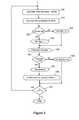
- FIG. 3is a flow diagram of an algorithm to detect conditions likely to cause the diagnostic algorithm to generate a false detection of a shockable rhythm.
- an automated external defibrillatorcomprises three main sections: 10 , 12 and 14 .
- Section 10is the main high voltage shock circuitry and comprises a bank of capacitors 16 which are charged up to a high voltage by a charging circuit 18 , the charge being released as a bi-phasic high voltage shock through a pair of patient electrodes 20 by a bridge circuit 22 .
- the charging of the capacitors 16 and the shape and duration of the bi-phasic shock waveformis controlled by a microprocessor 24 , the actual shock being given by the user pressing a button (not shown) if the patient's condition is deemed “shockable” as determined by a diagnostic algorithm having the patient's ECG as input.
- the ECGis derived from the patient electrodes 20 in known manner, not shown.
- the processis prompted by voice messages and/or visual prompts output on visual/audio indicators 38 (the indicators are shown in section 12 for diagrammatic simplicity).
- the audio/visual output indicators 38may comprise a loudspeaker and/or LED(s).
- Section 12measures the patient's transthoracic impedance using the same electrodes 20 as are used for applying the shock.
- a generator 26produces a 30 kilohertz sinusoidal waveform at a constant current of 100 microamperes. This signal is applied across the electrodes 20 .
- a voltage across the electrodesis generated which is superimposed on the 30 kHz sinusoid. This voltage is a direct measurement of the transthoracic impedance of the patient.
- the voltage generated in response to the sinusoidis applied to a differential amplifier 28 which converts it from a differential signal to a single signal referenced to ground potential.
- the resultant waveformis passed through a low pass filter 30 which removes the original 30 kHz signal leaving a signal Zo (static impedance) which is directly proportional to the patient impedance.
- the impedance signal Zois used by the microprocessor 24 to set the bi-phasic pulse amplitude and width to ensure that the correct total energy (typically 150 Joules) is delivered to the patient.
- sections 10 and 12 of the AEDare well-known, and it is not thought that further detail is necessary.
- section 14The purpose of section 14 is to provide further conditioning of the impedance signal Zo as input to an algorithm to detect circumstances likely to cause the main diagnostic algorithm to generate a false detection of a shockable rhythm. Section 14 is additional to the existing circuitry for the derivation of patient impedance in section 12 .
- the impedance signal Zo which is output from the low pass filter 30is passed through a high pass filter 32 which removes the dc offset before removing higher frequency noise in the low pass filter 34 .
- the signalis scaled in an amplifier 36 incorporating digital gain control to a level appropriate for analogue-to-digital conversion by the microprocessor 24 .
- the resultant filtered and amplified signal Zis digitally converted.
- the analog to digital sample rateis 170.66 samples per second.
- the impedance signal Zis differentiated and the result dZ/dt is used in an algorithm, FIG. 3 , to detect interference conditions likely to cause the diagnostic algorithm to cause it to generate a false detection of a shockable rhythm.
- FIG. 2shows a typical dZ/dt waveform during periods of no interference and interference respectively.
- the signalOn the left the signal has a relatively low energy, corresponding to a period when the patient and the electrodes are undisturbed.
- the signalOn the right, however, the signal becomes relatively much more energetic, corresponding to a period when the patient and/or electrodes are disturbed sufficiently to cause, or be likely to cause, the diagnostic algorithm to generate a false detection of a shockable rhythm.
- the algorithm of FIG. 3is therefore designed to detect periods when the energy of dZ/dt is above a threshold level likely to cause false detection.
- the algorithmdetects disturbances likely to cause the diagnostic algorithm to generate a false detection of a shockable rhythm by forming the first derivative of Z (dZ/dt), deriving a signal related to the energy of dZ/dt in a moving time window, and determining if the energy signal exceeds a certain (empirically determined) threshold level.
- the diagnostic algorithm in the defibrillatoris prevented from detecting a shockable rhythm for a period of, in this embodiment, 4 seconds (step 190 ).
- step 200The process continues (step 200 ) until no more Z values are input, i.e. the Z signal is no longer present.
- the threshold value used in step 120 of this embodimentwas obtained empirically by analysing a large volume of patient data when interferences was documented. Additionally, the threshold value depends on the A-D sample rate, the gain from the amplifier 36 , the resolution of Z, the length of the moving time window, the technique used for calculating dZ/dt, etc.
- the average calculated at step 150is a measure of the energy of the dZ/dt signal over the preceding 0.75 s window. That is to say, the more often the amplitude of dZ/dt exceeds the threshold in the moving window, the greater the energy of the signal.
- the RMS value of the signalcan be calculated, or peak-to-peak value.
Landscapes
- Health & Medical Sciences (AREA)
- Life Sciences & Earth Sciences (AREA)
- Engineering & Computer Science (AREA)
- Veterinary Medicine (AREA)
- Heart & Thoracic Surgery (AREA)
- Biomedical Technology (AREA)
- Animal Behavior & Ethology (AREA)
- General Health & Medical Sciences (AREA)
- Public Health (AREA)
- Cardiology (AREA)
- Signal Processing (AREA)
- Biophysics (AREA)
- Physics & Mathematics (AREA)
- Surgery (AREA)
- Molecular Biology (AREA)
- Medical Informatics (AREA)
- Pathology (AREA)
- Nuclear Medicine, Radiotherapy & Molecular Imaging (AREA)
- Radiology & Medical Imaging (AREA)
- Psychiatry (AREA)
- Physiology (AREA)
- Computer Vision & Pattern Recognition (AREA)
- Artificial Intelligence (AREA)
- Hematology (AREA)
- Electrotherapy Devices (AREA)
Abstract
Description
- a. At
step 100 the signal Z is differentiated by software in themicroprocessor 24 to obtain its first derivative dZ/dt. - b. Next,
step 110, the amplitude of dZ/dt is calculated. - c. Next,
step 120, if the amplitude of the signal dZ/dt is greater than a certain threshold a flag is set to 1,step 130, otherwise the flag is set to 0,step 140. - d. The flag values (0 or 1) are averaged over the last 0.75 s,
step 150. This is done by feeding a binary array of 128 elements (equivalent to 0.75 s using a 170.66 sample rate). The oldest value in the array is substituted by the newest one, and the elements of the binary array are summed and divided by 128. - e. If this average is greater than 0.5,
step 160, which means that most of the time dZ/dt has been higher than the threshold, the algorithm flags that it has detected interference or disturbance likely to cause the diagnostic algorithm to generate a false detection of a shockable rhythm (step170). Otherwise no interference or disturbance is detected,step 180.
Claims (20)
Applications Claiming Priority (3)
| Application Number | Priority Date | Filing Date | Title |
|---|---|---|---|
| IES2010/0746 | 2010-11-29 | ||
| IES20100746 | 2010-11-29 | ||
| PCT/EP2011/071069WO2012072518A1 (en) | 2010-11-29 | 2011-11-25 | An external defibrillator |
Related Parent Applications (1)
| Application Number | Title | Priority Date | Filing Date |
|---|---|---|---|
| PCT/EP2011/071069A-371-Of-InternationalWO2012072518A1 (en) | 2010-11-29 | 2011-11-25 | An external defibrillator |
Related Child Applications (1)
| Application Number | Title | Priority Date | Filing Date |
|---|---|---|---|
| US14/561,571ContinuationUS9238146B2 (en) | 2010-11-29 | 2014-12-05 | External defibrillator |
Publications (2)
| Publication Number | Publication Date |
|---|---|
| US20130245708A1 US20130245708A1 (en) | 2013-09-19 |
| US8909336B2true US8909336B2 (en) | 2014-12-09 |
Family
ID=45034009
Family Applications (2)
| Application Number | Title | Priority Date | Filing Date |
|---|---|---|---|
| US13/990,059ActiveUS8909336B2 (en) | 2010-11-29 | 2011-11-25 | External defibrillator |
| US14/561,571ActiveUS9238146B2 (en) | 2010-11-29 | 2014-12-05 | External defibrillator |
Family Applications After (1)
| Application Number | Title | Priority Date | Filing Date |
|---|---|---|---|
| US14/561,571ActiveUS9238146B2 (en) | 2010-11-29 | 2014-12-05 | External defibrillator |
Country Status (5)
| Country | Link |
|---|---|
| US (2) | US8909336B2 (en) |
| EP (1) | EP2646111B1 (en) |
| JP (1) | JP6373006B2 (en) |
| AU (1) | AU2011335129B2 (en) |
| WO (1) | WO2012072518A1 (en) |
Cited By (72)
| Publication number | Priority date | Publication date | Assignee | Title |
|---|---|---|---|---|
| US9853743B2 (en) | 2015-08-20 | 2017-12-26 | Cardiac Pacemakers, Inc. | Systems and methods for communication between medical devices |
| US10029107B1 (en) | 2017-01-26 | 2018-07-24 | Cardiac Pacemakers, Inc. | Leadless device with overmolded components |
| US10046167B2 (en) | 2015-02-09 | 2018-08-14 | Cardiac Pacemakers, Inc. | Implantable medical device with radiopaque ID tag |
| US10065041B2 (en) | 2015-10-08 | 2018-09-04 | Cardiac Pacemakers, Inc. | Devices and methods for adjusting pacing rates in an implantable medical device |
| US10137305B2 (en) | 2015-08-28 | 2018-11-27 | Cardiac Pacemakers, Inc. | Systems and methods for behaviorally responsive signal detection and therapy delivery |
| US10159842B2 (en) | 2015-08-28 | 2018-12-25 | Cardiac Pacemakers, Inc. | System and method for detecting tamponade |
| US10183170B2 (en) | 2015-12-17 | 2019-01-22 | Cardiac Pacemakers, Inc. | Conducted communication in a medical device system |
| US10220213B2 (en) | 2015-02-06 | 2019-03-05 | Cardiac Pacemakers, Inc. | Systems and methods for safe delivery of electrical stimulation therapy |
| US10226631B2 (en) | 2015-08-28 | 2019-03-12 | Cardiac Pacemakers, Inc. | Systems and methods for infarct detection |
| US10328272B2 (en) | 2016-05-10 | 2019-06-25 | Cardiac Pacemakers, Inc. | Retrievability for implantable medical devices |
| US10350423B2 (en) | 2016-02-04 | 2019-07-16 | Cardiac Pacemakers, Inc. | Delivery system with force sensor for leadless cardiac device |
| US10357159B2 (en) | 2015-08-20 | 2019-07-23 | Cardiac Pacemakers, Inc | Systems and methods for communication between medical devices |
| US10391319B2 (en) | 2016-08-19 | 2019-08-27 | Cardiac Pacemakers, Inc. | Trans septal implantable medical device |
| US10413733B2 (en) | 2016-10-27 | 2019-09-17 | Cardiac Pacemakers, Inc. | Implantable medical device with gyroscope |
| US10426962B2 (en) | 2016-07-07 | 2019-10-01 | Cardiac Pacemakers, Inc. | Leadless pacemaker using pressure measurements for pacing capture verification |
| US10434317B2 (en) | 2016-10-31 | 2019-10-08 | Cardiac Pacemakers, Inc. | Systems and methods for activity level pacing |
| US10434314B2 (en) | 2016-10-27 | 2019-10-08 | Cardiac Pacemakers, Inc. | Use of a separate device in managing the pace pulse energy of a cardiac pacemaker |
| US10463305B2 (en) | 2016-10-27 | 2019-11-05 | Cardiac Pacemakers, Inc. | Multi-device cardiac resynchronization therapy with timing enhancements |
| US10512784B2 (en) | 2016-06-27 | 2019-12-24 | Cardiac Pacemakers, Inc. | Cardiac therapy system using subcutaneously sensed P-waves for resynchronization pacing management |
| US10561330B2 (en) | 2016-10-27 | 2020-02-18 | Cardiac Pacemakers, Inc. | Implantable medical device having a sense channel with performance adjustment |
| US10583303B2 (en) | 2016-01-19 | 2020-03-10 | Cardiac Pacemakers, Inc. | Devices and methods for wirelessly recharging a rechargeable battery of an implantable medical device |
| US10583301B2 (en) | 2016-11-08 | 2020-03-10 | Cardiac Pacemakers, Inc. | Implantable medical device for atrial deployment |
| US10617874B2 (en) | 2016-10-31 | 2020-04-14 | Cardiac Pacemakers, Inc. | Systems and methods for activity level pacing |
| US10632313B2 (en) | 2016-11-09 | 2020-04-28 | Cardiac Pacemakers, Inc. | Systems, devices, and methods for setting cardiac pacing pulse parameters for a cardiac pacing device |
| US10639486B2 (en) | 2016-11-21 | 2020-05-05 | Cardiac Pacemakers, Inc. | Implantable medical device with recharge coil |
| US10668294B2 (en) | 2016-05-10 | 2020-06-02 | Cardiac Pacemakers, Inc. | Leadless cardiac pacemaker configured for over the wire delivery |
| US10688304B2 (en) | 2016-07-20 | 2020-06-23 | Cardiac Pacemakers, Inc. | Method and system for utilizing an atrial contraction timing fiducial in a leadless cardiac pacemaker system |
| US10737102B2 (en) | 2017-01-26 | 2020-08-11 | Cardiac Pacemakers, Inc. | Leadless implantable device with detachable fixation |
| US10758724B2 (en) | 2016-10-27 | 2020-09-01 | Cardiac Pacemakers, Inc. | Implantable medical device delivery system with integrated sensor |
| US10758737B2 (en) | 2016-09-21 | 2020-09-01 | Cardiac Pacemakers, Inc. | Using sensor data from an intracardially implanted medical device to influence operation of an extracardially implantable cardioverter |
| US10765871B2 (en) | 2016-10-27 | 2020-09-08 | Cardiac Pacemakers, Inc. | Implantable medical device with pressure sensor |
| US10780278B2 (en) | 2016-08-24 | 2020-09-22 | Cardiac Pacemakers, Inc. | Integrated multi-device cardiac resynchronization therapy using P-wave to pace timing |
| US10821288B2 (en) | 2017-04-03 | 2020-11-03 | Cardiac Pacemakers, Inc. | Cardiac pacemaker with pacing pulse energy adjustment based on sensed heart rate |
| US10835753B2 (en) | 2017-01-26 | 2020-11-17 | Cardiac Pacemakers, Inc. | Intra-body device communication with redundant message transmission |
| US10870008B2 (en) | 2016-08-24 | 2020-12-22 | Cardiac Pacemakers, Inc. | Cardiac resynchronization using fusion promotion for timing management |
| US10874861B2 (en) | 2018-01-04 | 2020-12-29 | Cardiac Pacemakers, Inc. | Dual chamber pacing without beat-to-beat communication |
| US10881863B2 (en) | 2016-11-21 | 2021-01-05 | Cardiac Pacemakers, Inc. | Leadless cardiac pacemaker with multimode communication |
| US10881869B2 (en) | 2016-11-21 | 2021-01-05 | Cardiac Pacemakers, Inc. | Wireless re-charge of an implantable medical device |
| US10894163B2 (en) | 2016-11-21 | 2021-01-19 | Cardiac Pacemakers, Inc. | LCP based predictive timing for cardiac resynchronization |
| US10905889B2 (en) | 2016-09-21 | 2021-02-02 | Cardiac Pacemakers, Inc. | Leadless stimulation device with a housing that houses internal components of the leadless stimulation device and functions as the battery case and a terminal of an internal battery |
| US10905872B2 (en) | 2017-04-03 | 2021-02-02 | Cardiac Pacemakers, Inc. | Implantable medical device with a movable electrode biased toward an extended position |
| US10905886B2 (en) | 2015-12-28 | 2021-02-02 | Cardiac Pacemakers, Inc. | Implantable medical device for deployment across the atrioventricular septum |
| US10918875B2 (en) | 2017-08-18 | 2021-02-16 | Cardiac Pacemakers, Inc. | Implantable medical device with a flux concentrator and a receiving coil disposed about the flux concentrator |
| US10994145B2 (en) | 2016-09-21 | 2021-05-04 | Cardiac Pacemakers, Inc. | Implantable cardiac monitor |
| US11052258B2 (en) | 2017-12-01 | 2021-07-06 | Cardiac Pacemakers, Inc. | Methods and systems for detecting atrial contraction timing fiducials within a search window from a ventricularly implanted leadless cardiac pacemaker |
| US11058880B2 (en) | 2018-03-23 | 2021-07-13 | Medtronic, Inc. | VFA cardiac therapy for tachycardia |
| US11065459B2 (en) | 2017-08-18 | 2021-07-20 | Cardiac Pacemakers, Inc. | Implantable medical device with pressure sensor |
| US11071870B2 (en) | 2017-12-01 | 2021-07-27 | Cardiac Pacemakers, Inc. | Methods and systems for detecting atrial contraction timing fiducials and determining a cardiac interval from a ventricularly implanted leadless cardiac pacemaker |
| US11116988B2 (en) | 2016-03-31 | 2021-09-14 | Cardiac Pacemakers, Inc. | Implantable medical device with rechargeable battery |
| US11147979B2 (en) | 2016-11-21 | 2021-10-19 | Cardiac Pacemakers, Inc. | Implantable medical device with a magnetically permeable housing and an inductive coil disposed about the housing |
| US11185703B2 (en) | 2017-11-07 | 2021-11-30 | Cardiac Pacemakers, Inc. | Leadless cardiac pacemaker for bundle of his pacing |
| US11207532B2 (en) | 2017-01-04 | 2021-12-28 | Cardiac Pacemakers, Inc. | Dynamic sensing updates using postural input in a multiple device cardiac rhythm management system |
| US11207527B2 (en) | 2016-07-06 | 2021-12-28 | Cardiac Pacemakers, Inc. | Method and system for determining an atrial contraction timing fiducial in a leadless cardiac pacemaker system |
| US11213676B2 (en) | 2019-04-01 | 2022-01-04 | Medtronic, Inc. | Delivery systems for VfA cardiac therapy |
| US11235161B2 (en) | 2018-09-26 | 2022-02-01 | Medtronic, Inc. | Capture in ventricle-from-atrium cardiac therapy |
| US11235159B2 (en) | 2018-03-23 | 2022-02-01 | Medtronic, Inc. | VFA cardiac resynchronization therapy |
| US11235163B2 (en) | 2017-09-20 | 2022-02-01 | Cardiac Pacemakers, Inc. | Implantable medical device with multiple modes of operation |
| US11260216B2 (en) | 2017-12-01 | 2022-03-01 | Cardiac Pacemakers, Inc. | Methods and systems for detecting atrial contraction timing fiducials during ventricular filling from a ventricularly implanted leadless cardiac pacemaker |
| US11285326B2 (en) | 2015-03-04 | 2022-03-29 | Cardiac Pacemakers, Inc. | Systems and methods for treating cardiac arrhythmias |
| US11305127B2 (en) | 2019-08-26 | 2022-04-19 | Medtronic Inc. | VfA delivery and implant region detection |
| US11400296B2 (en) | 2018-03-23 | 2022-08-02 | Medtronic, Inc. | AV synchronous VfA cardiac therapy |
| WO2022167919A1 (en)* | 2021-02-03 | 2022-08-11 | Cellaed Life Saver Pty Ltd | Automated external defibrillators with multiple, multifunctional electrode pairs |
| US11529523B2 (en) | 2018-01-04 | 2022-12-20 | Cardiac Pacemakers, Inc. | Handheld bridge device for providing a communication bridge between an implanted medical device and a smartphone |
| US11679265B2 (en) | 2019-02-14 | 2023-06-20 | Medtronic, Inc. | Lead-in-lead systems and methods for cardiac therapy |
| US11697025B2 (en) | 2019-03-29 | 2023-07-11 | Medtronic, Inc. | Cardiac conduction system capture |
| US11712188B2 (en) | 2019-05-07 | 2023-08-01 | Medtronic, Inc. | Posterior left bundle branch engagement |
| US11813464B2 (en) | 2020-07-31 | 2023-11-14 | Medtronic, Inc. | Cardiac conduction system evaluation |
| US11813463B2 (en) | 2017-12-01 | 2023-11-14 | Cardiac Pacemakers, Inc. | Leadless cardiac pacemaker with reversionary behavior |
| US11813466B2 (en) | 2020-01-27 | 2023-11-14 | Medtronic, Inc. | Atrioventricular nodal stimulation |
| US11911168B2 (en) | 2020-04-03 | 2024-02-27 | Medtronic, Inc. | Cardiac conduction system therapy benefit determination |
| US11951313B2 (en) | 2018-11-17 | 2024-04-09 | Medtronic, Inc. | VFA delivery systems and methods |
| US12296177B2 (en) | 2018-12-21 | 2025-05-13 | Medtronic, Inc. | Delivery systems and methods for left ventricular pacing |
Families Citing this family (11)
| Publication number | Priority date | Publication date | Assignee | Title |
|---|---|---|---|---|
| US8868179B2 (en) | 2011-11-11 | 2014-10-21 | Zoll Medical Corporation | Determination for effective defibrillation |
| US8948859B2 (en) | 2012-06-11 | 2015-02-03 | Zoll Medical Corporation | Resuscitation enhancements |
| EP2967395A4 (en) | 2013-03-14 | 2016-03-16 | Zoll Medical Corp | Windowing for identifying shock outcome |
| CN105263564A (en) | 2013-03-14 | 2016-01-20 | 佐尔医药公司 | Shock determination based on prior shocks |
| US9782093B2 (en) | 2014-03-14 | 2017-10-10 | Zoll Medical Corporation | Vector-based shock indication |
| US20150352369A1 (en) | 2014-06-10 | 2015-12-10 | Zoll Medical Corporation | Selecting energy escalation for defibrillation |
| US10039925B2 (en) | 2014-06-10 | 2018-08-07 | Zoll Medical Corporation | Determining initial treatments from spectral data |
| US11324443B2 (en) | 2015-03-26 | 2022-05-10 | Zoll Medical Corporation | Amplitude spectrum area considerations for an external medical monitoring and treatment device |
| US10716949B2 (en) | 2018-03-19 | 2020-07-21 | Zoll Medical Corporation | Changing cardiac shock delivery parameters based on a transform value |
| JP7280641B2 (en)* | 2019-10-24 | 2023-05-24 | 一般社団法人メディカル・イノベーション・コンソーシアム | automated external defibrillator |
| KR20240165053A (en)* | 2023-05-15 | 2024-11-22 | 주식회사메디아나 | A defibrillation system to produce dual sequential defibrillation shocks |
Citations (8)
| Publication number | Priority date | Publication date | Assignee | Title |
|---|---|---|---|---|
| US4619265A (en) | 1984-03-08 | 1986-10-28 | Physio-Control Corporation | Interactive portable defibrillator including ECG detection circuit |
| US5247939A (en) | 1992-01-10 | 1993-09-28 | Physio-Control Corporation | Detection of electrode/patient motion and fast restore limits |
| US6287328B1 (en) | 1999-04-08 | 2001-09-11 | Agilent Technologies, Inc. | Multivariable artifact assessment |
| US20060025825A1 (en) | 2004-07-30 | 2006-02-02 | Bowers Kyle R | Method and apparatus for detecting artifact signals in the electrocardiogram of a patient caused by CPR and/or patient motion using patient impedance |
| WO2009109595A1 (en) | 2008-03-05 | 2009-09-11 | Heartsine Technologies Limited | The development and implementation of an adaptive filter technique for the assessment of circulatory collapse. |
| EP2171245A1 (en) | 2007-07-26 | 2010-04-07 | Behr GmbH & Co. KG | Apparatus for cooling recirculated exhaust gas of an internal combustion engine |
| US20110224746A1 (en) | 2010-03-12 | 2011-09-15 | Schiller Medical S.A.S. | Method, Apparatus and Computer Program for Defibrillation Delivery Decision |
| US20120302896A1 (en)* | 1999-09-30 | 2012-11-29 | Physio-Control, Inc. | Pulse detection apparatus, software, and methods using patient physiological signals |
Family Cites Families (2)
| Publication number | Priority date | Publication date | Assignee | Title |
|---|---|---|---|---|
| US20040116969A1 (en)* | 2002-08-26 | 2004-06-17 | Owen James M. | Pulse detection using patient physiological signals |
| EP2172245B1 (en)* | 2008-10-03 | 2017-04-12 | Schiller Medical S.A.S. | Apparatus for defibrillation delivery decision |
- 2011
- 2011-11-25AUAU2011335129Apatent/AU2011335129B2/enactiveActive
- 2011-11-25WOPCT/EP2011/071069patent/WO2012072518A1/enactiveApplication Filing
- 2011-11-25EPEP11787911.4Apatent/EP2646111B1/enactiveActive
- 2011-11-25JPJP2013540383Apatent/JP6373006B2/enactiveActive
- 2011-11-25USUS13/990,059patent/US8909336B2/enactiveActive
- 2014
- 2014-12-05USUS14/561,571patent/US9238146B2/enactiveActive
Patent Citations (8)
| Publication number | Priority date | Publication date | Assignee | Title |
|---|---|---|---|---|
| US4619265A (en) | 1984-03-08 | 1986-10-28 | Physio-Control Corporation | Interactive portable defibrillator including ECG detection circuit |
| US5247939A (en) | 1992-01-10 | 1993-09-28 | Physio-Control Corporation | Detection of electrode/patient motion and fast restore limits |
| US6287328B1 (en) | 1999-04-08 | 2001-09-11 | Agilent Technologies, Inc. | Multivariable artifact assessment |
| US20120302896A1 (en)* | 1999-09-30 | 2012-11-29 | Physio-Control, Inc. | Pulse detection apparatus, software, and methods using patient physiological signals |
| US20060025825A1 (en) | 2004-07-30 | 2006-02-02 | Bowers Kyle R | Method and apparatus for detecting artifact signals in the electrocardiogram of a patient caused by CPR and/or patient motion using patient impedance |
| EP2171245A1 (en) | 2007-07-26 | 2010-04-07 | Behr GmbH & Co. KG | Apparatus for cooling recirculated exhaust gas of an internal combustion engine |
| WO2009109595A1 (en) | 2008-03-05 | 2009-09-11 | Heartsine Technologies Limited | The development and implementation of an adaptive filter technique for the assessment of circulatory collapse. |
| US20110224746A1 (en) | 2010-03-12 | 2011-09-15 | Schiller Medical S.A.S. | Method, Apparatus and Computer Program for Defibrillation Delivery Decision |
Cited By (85)
| Publication number | Priority date | Publication date | Assignee | Title |
|---|---|---|---|---|
| US10220213B2 (en) | 2015-02-06 | 2019-03-05 | Cardiac Pacemakers, Inc. | Systems and methods for safe delivery of electrical stimulation therapy |
| US11224751B2 (en) | 2015-02-06 | 2022-01-18 | Cardiac Pacemakers, Inc. | Systems and methods for safe delivery of electrical stimulation therapy |
| US11020600B2 (en) | 2015-02-09 | 2021-06-01 | Cardiac Pacemakers, Inc. | Implantable medical device with radiopaque ID tag |
| US10046167B2 (en) | 2015-02-09 | 2018-08-14 | Cardiac Pacemakers, Inc. | Implantable medical device with radiopaque ID tag |
| US11285326B2 (en) | 2015-03-04 | 2022-03-29 | Cardiac Pacemakers, Inc. | Systems and methods for treating cardiac arrhythmias |
| US9853743B2 (en) | 2015-08-20 | 2017-12-26 | Cardiac Pacemakers, Inc. | Systems and methods for communication between medical devices |
| US10357159B2 (en) | 2015-08-20 | 2019-07-23 | Cardiac Pacemakers, Inc | Systems and methods for communication between medical devices |
| US10226631B2 (en) | 2015-08-28 | 2019-03-12 | Cardiac Pacemakers, Inc. | Systems and methods for infarct detection |
| US10589101B2 (en) | 2015-08-28 | 2020-03-17 | Cardiac Pacemakers, Inc. | System and method for detecting tamponade |
| US10159842B2 (en) | 2015-08-28 | 2018-12-25 | Cardiac Pacemakers, Inc. | System and method for detecting tamponade |
| US10137305B2 (en) | 2015-08-28 | 2018-11-27 | Cardiac Pacemakers, Inc. | Systems and methods for behaviorally responsive signal detection and therapy delivery |
| US10065041B2 (en) | 2015-10-08 | 2018-09-04 | Cardiac Pacemakers, Inc. | Devices and methods for adjusting pacing rates in an implantable medical device |
| US10183170B2 (en) | 2015-12-17 | 2019-01-22 | Cardiac Pacemakers, Inc. | Conducted communication in a medical device system |
| US10933245B2 (en) | 2015-12-17 | 2021-03-02 | Cardiac Pacemakers, Inc. | Conducted communication in a medical device system |
| US10905886B2 (en) | 2015-12-28 | 2021-02-02 | Cardiac Pacemakers, Inc. | Implantable medical device for deployment across the atrioventricular septum |
| US10583303B2 (en) | 2016-01-19 | 2020-03-10 | Cardiac Pacemakers, Inc. | Devices and methods for wirelessly recharging a rechargeable battery of an implantable medical device |
| US10350423B2 (en) | 2016-02-04 | 2019-07-16 | Cardiac Pacemakers, Inc. | Delivery system with force sensor for leadless cardiac device |
| US11116988B2 (en) | 2016-03-31 | 2021-09-14 | Cardiac Pacemakers, Inc. | Implantable medical device with rechargeable battery |
| US10668294B2 (en) | 2016-05-10 | 2020-06-02 | Cardiac Pacemakers, Inc. | Leadless cardiac pacemaker configured for over the wire delivery |
| US10328272B2 (en) | 2016-05-10 | 2019-06-25 | Cardiac Pacemakers, Inc. | Retrievability for implantable medical devices |
| US10512784B2 (en) | 2016-06-27 | 2019-12-24 | Cardiac Pacemakers, Inc. | Cardiac therapy system using subcutaneously sensed P-waves for resynchronization pacing management |
| US11497921B2 (en) | 2016-06-27 | 2022-11-15 | Cardiac Pacemakers, Inc. | Cardiac therapy system using subcutaneously sensed p-waves for resynchronization pacing management |
| US11207527B2 (en) | 2016-07-06 | 2021-12-28 | Cardiac Pacemakers, Inc. | Method and system for determining an atrial contraction timing fiducial in a leadless cardiac pacemaker system |
| US10426962B2 (en) | 2016-07-07 | 2019-10-01 | Cardiac Pacemakers, Inc. | Leadless pacemaker using pressure measurements for pacing capture verification |
| US10688304B2 (en) | 2016-07-20 | 2020-06-23 | Cardiac Pacemakers, Inc. | Method and system for utilizing an atrial contraction timing fiducial in a leadless cardiac pacemaker system |
| US10391319B2 (en) | 2016-08-19 | 2019-08-27 | Cardiac Pacemakers, Inc. | Trans septal implantable medical device |
| US10780278B2 (en) | 2016-08-24 | 2020-09-22 | Cardiac Pacemakers, Inc. | Integrated multi-device cardiac resynchronization therapy using P-wave to pace timing |
| US11464982B2 (en) | 2016-08-24 | 2022-10-11 | Cardiac Pacemakers, Inc. | Integrated multi-device cardiac resynchronization therapy using p-wave to pace timing |
| US10870008B2 (en) | 2016-08-24 | 2020-12-22 | Cardiac Pacemakers, Inc. | Cardiac resynchronization using fusion promotion for timing management |
| US10994145B2 (en) | 2016-09-21 | 2021-05-04 | Cardiac Pacemakers, Inc. | Implantable cardiac monitor |
| US10905889B2 (en) | 2016-09-21 | 2021-02-02 | Cardiac Pacemakers, Inc. | Leadless stimulation device with a housing that houses internal components of the leadless stimulation device and functions as the battery case and a terminal of an internal battery |
| US10758737B2 (en) | 2016-09-21 | 2020-09-01 | Cardiac Pacemakers, Inc. | Using sensor data from an intracardially implanted medical device to influence operation of an extracardially implantable cardioverter |
| US11305125B2 (en) | 2016-10-27 | 2022-04-19 | Cardiac Pacemakers, Inc. | Implantable medical device with gyroscope |
| US10765871B2 (en) | 2016-10-27 | 2020-09-08 | Cardiac Pacemakers, Inc. | Implantable medical device with pressure sensor |
| US10561330B2 (en) | 2016-10-27 | 2020-02-18 | Cardiac Pacemakers, Inc. | Implantable medical device having a sense channel with performance adjustment |
| US10463305B2 (en) | 2016-10-27 | 2019-11-05 | Cardiac Pacemakers, Inc. | Multi-device cardiac resynchronization therapy with timing enhancements |
| US10434314B2 (en) | 2016-10-27 | 2019-10-08 | Cardiac Pacemakers, Inc. | Use of a separate device in managing the pace pulse energy of a cardiac pacemaker |
| US10758724B2 (en) | 2016-10-27 | 2020-09-01 | Cardiac Pacemakers, Inc. | Implantable medical device delivery system with integrated sensor |
| US10413733B2 (en) | 2016-10-27 | 2019-09-17 | Cardiac Pacemakers, Inc. | Implantable medical device with gyroscope |
| US10434317B2 (en) | 2016-10-31 | 2019-10-08 | Cardiac Pacemakers, Inc. | Systems and methods for activity level pacing |
| US10617874B2 (en) | 2016-10-31 | 2020-04-14 | Cardiac Pacemakers, Inc. | Systems and methods for activity level pacing |
| US10583301B2 (en) | 2016-11-08 | 2020-03-10 | Cardiac Pacemakers, Inc. | Implantable medical device for atrial deployment |
| US10632313B2 (en) | 2016-11-09 | 2020-04-28 | Cardiac Pacemakers, Inc. | Systems, devices, and methods for setting cardiac pacing pulse parameters for a cardiac pacing device |
| US10881869B2 (en) | 2016-11-21 | 2021-01-05 | Cardiac Pacemakers, Inc. | Wireless re-charge of an implantable medical device |
| US10639486B2 (en) | 2016-11-21 | 2020-05-05 | Cardiac Pacemakers, Inc. | Implantable medical device with recharge coil |
| US10894163B2 (en) | 2016-11-21 | 2021-01-19 | Cardiac Pacemakers, Inc. | LCP based predictive timing for cardiac resynchronization |
| US10881863B2 (en) | 2016-11-21 | 2021-01-05 | Cardiac Pacemakers, Inc. | Leadless cardiac pacemaker with multimode communication |
| US11147979B2 (en) | 2016-11-21 | 2021-10-19 | Cardiac Pacemakers, Inc. | Implantable medical device with a magnetically permeable housing and an inductive coil disposed about the housing |
| US11207532B2 (en) | 2017-01-04 | 2021-12-28 | Cardiac Pacemakers, Inc. | Dynamic sensing updates using postural input in a multiple device cardiac rhythm management system |
| US10737102B2 (en) | 2017-01-26 | 2020-08-11 | Cardiac Pacemakers, Inc. | Leadless implantable device with detachable fixation |
| US11590353B2 (en) | 2017-01-26 | 2023-02-28 | Cardiac Pacemakers, Inc. | Intra-body device communication with redundant message transmission |
| US10029107B1 (en) | 2017-01-26 | 2018-07-24 | Cardiac Pacemakers, Inc. | Leadless device with overmolded components |
| US10835753B2 (en) | 2017-01-26 | 2020-11-17 | Cardiac Pacemakers, Inc. | Intra-body device communication with redundant message transmission |
| US10905872B2 (en) | 2017-04-03 | 2021-02-02 | Cardiac Pacemakers, Inc. | Implantable medical device with a movable electrode biased toward an extended position |
| US10821288B2 (en) | 2017-04-03 | 2020-11-03 | Cardiac Pacemakers, Inc. | Cardiac pacemaker with pacing pulse energy adjustment based on sensed heart rate |
| US11065459B2 (en) | 2017-08-18 | 2021-07-20 | Cardiac Pacemakers, Inc. | Implantable medical device with pressure sensor |
| US12151116B2 (en) | 2017-08-18 | 2024-11-26 | Cardiac Pacemakers, Inc. | Implantable medical device with pressure sensor |
| US10918875B2 (en) | 2017-08-18 | 2021-02-16 | Cardiac Pacemakers, Inc. | Implantable medical device with a flux concentrator and a receiving coil disposed about the flux concentrator |
| US11235163B2 (en) | 2017-09-20 | 2022-02-01 | Cardiac Pacemakers, Inc. | Implantable medical device with multiple modes of operation |
| US11185703B2 (en) | 2017-11-07 | 2021-11-30 | Cardiac Pacemakers, Inc. | Leadless cardiac pacemaker for bundle of his pacing |
| US11071870B2 (en) | 2017-12-01 | 2021-07-27 | Cardiac Pacemakers, Inc. | Methods and systems for detecting atrial contraction timing fiducials and determining a cardiac interval from a ventricularly implanted leadless cardiac pacemaker |
| US11813463B2 (en) | 2017-12-01 | 2023-11-14 | Cardiac Pacemakers, Inc. | Leadless cardiac pacemaker with reversionary behavior |
| US11260216B2 (en) | 2017-12-01 | 2022-03-01 | Cardiac Pacemakers, Inc. | Methods and systems for detecting atrial contraction timing fiducials during ventricular filling from a ventricularly implanted leadless cardiac pacemaker |
| US11052258B2 (en) | 2017-12-01 | 2021-07-06 | Cardiac Pacemakers, Inc. | Methods and systems for detecting atrial contraction timing fiducials within a search window from a ventricularly implanted leadless cardiac pacemaker |
| US11529523B2 (en) | 2018-01-04 | 2022-12-20 | Cardiac Pacemakers, Inc. | Handheld bridge device for providing a communication bridge between an implanted medical device and a smartphone |
| US10874861B2 (en) | 2018-01-04 | 2020-12-29 | Cardiac Pacemakers, Inc. | Dual chamber pacing without beat-to-beat communication |
| US11235159B2 (en) | 2018-03-23 | 2022-02-01 | Medtronic, Inc. | VFA cardiac resynchronization therapy |
| US11400296B2 (en) | 2018-03-23 | 2022-08-02 | Medtronic, Inc. | AV synchronous VfA cardiac therapy |
| US11058880B2 (en) | 2018-03-23 | 2021-07-13 | Medtronic, Inc. | VFA cardiac therapy for tachycardia |
| US11819699B2 (en) | 2018-03-23 | 2023-11-21 | Medtronic, Inc. | VfA cardiac resynchronization therapy |
| US11235161B2 (en) | 2018-09-26 | 2022-02-01 | Medtronic, Inc. | Capture in ventricle-from-atrium cardiac therapy |
| US12172021B2 (en) | 2018-09-26 | 2024-12-24 | Medtronic, Inc. | Capture in ventricle-from-atrium cardiac therapy |
| US11951313B2 (en) | 2018-11-17 | 2024-04-09 | Medtronic, Inc. | VFA delivery systems and methods |
| US12296177B2 (en) | 2018-12-21 | 2025-05-13 | Medtronic, Inc. | Delivery systems and methods for left ventricular pacing |
| US11679265B2 (en) | 2019-02-14 | 2023-06-20 | Medtronic, Inc. | Lead-in-lead systems and methods for cardiac therapy |
| US11697025B2 (en) | 2019-03-29 | 2023-07-11 | Medtronic, Inc. | Cardiac conduction system capture |
| US11213676B2 (en) | 2019-04-01 | 2022-01-04 | Medtronic, Inc. | Delivery systems for VfA cardiac therapy |
| US11712188B2 (en) | 2019-05-07 | 2023-08-01 | Medtronic, Inc. | Posterior left bundle branch engagement |
| US11305127B2 (en) | 2019-08-26 | 2022-04-19 | Medtronic Inc. | VfA delivery and implant region detection |
| US11813466B2 (en) | 2020-01-27 | 2023-11-14 | Medtronic, Inc. | Atrioventricular nodal stimulation |
| US11911168B2 (en) | 2020-04-03 | 2024-02-27 | Medtronic, Inc. | Cardiac conduction system therapy benefit determination |
| US11813464B2 (en) | 2020-07-31 | 2023-11-14 | Medtronic, Inc. | Cardiac conduction system evaluation |
| WO2022167919A1 (en)* | 2021-02-03 | 2022-08-11 | Cellaed Life Saver Pty Ltd | Automated external defibrillators with multiple, multifunctional electrode pairs |
| GB2618465A (en)* | 2021-02-03 | 2023-11-08 | Cellaed Life Saver Pty Ltd | Automated external defibrillators with multiple, multifunctional electrode pairs |
| AU2022215929B2 (en)* | 2021-02-03 | 2025-06-05 | Cellaed Life Saver Pty Ltd | Automated external defibrillators with multiple, multifunctional electrode pairs |
Also Published As
| Publication number | Publication date |
|---|---|
| JP2013543781A (en) | 2013-12-09 |
| US20130245708A1 (en) | 2013-09-19 |
| US9238146B2 (en) | 2016-01-19 |
| US20150088215A1 (en) | 2015-03-26 |
| AU2011335129A1 (en) | 2013-06-06 |
| JP6373006B2 (en) | 2018-08-15 |
| EP2646111B1 (en) | 2018-10-24 |
| WO2012072518A1 (en) | 2012-06-07 |
| AU2011335129B2 (en) | 2016-04-28 |
| EP2646111A1 (en) | 2013-10-09 |
Similar Documents
| Publication | Publication Date | Title |
|---|---|---|
| US8909336B2 (en) | External defibrillator | |
| US9155482B2 (en) | Apparatus and method for indicating cardiac output | |
| US9717924B2 (en) | External defibrillator with shock activated by cessation of precordial compressions | |
| US3857398A (en) | Electrical cardiac defibrillator | |
| JP5095742B2 (en) | Signal analysis in an implantable cardiac therapy device | |
| US9192775B2 (en) | Defibrillator with protocol for selectively interrupting CPR | |
| CN107249450B (en) | Methods and devices for atrial arrhythmic event detection | |
| JP6163203B2 (en) | Method and apparatus for analyzing cardiac rhythm during CPR | |
| US6044294A (en) | Methods and apparatus for measuring impedance in the body | |
| US5702425A (en) | Apparatus and method of noise classification in an implantable cardiac device | |
| US8868170B2 (en) | Active medical device, including an implantable defibrillator, for detection of QRS complexes in a very noisy signal | |
| US20130282068A1 (en) | Aed treatment recommendation method and device | |
| US20070213775A1 (en) | External Defibrillator With Pre-Cpr-Ecg Based Defibrillating Shock | |
| GB2446826A (en) | Resuscitation decision support | |
| US6269264B1 (en) | Method for measuring impedance in the body | |
| JPH06154186A (en) | Method for detecting atrial fibrillation and apparatus for detecting and curing of atrial fibrillation | |
| EP2527001B1 (en) | Testing of defibrillator electrodes | |
| KR102669382B1 (en) | Automated external defibrillator and method for electrocardiogram analysis and defibrillation thereof | |
| WO1980000006A1 (en) | Diagnostic apparatus |
Legal Events
| Date | Code | Title | Description |
|---|---|---|---|
| AS | Assignment | Owner name:HEARTSINE TECHNOLOGIES LIMITED, UNITED KINGDOM Free format text:ASSIGNMENT OF ASSIGNORS INTEREST;ASSIGNORS:NAVARRO-PAREDES, CESAR OSWALDO;ANDERSON, JOHN MCCUNE;SIGNING DATES FROM 20130606 TO 20130614;REEL/FRAME:030629/0981 | |
| STCF | Information on status: patent grant | Free format text:PATENTED CASE | |
| MAFP | Maintenance fee payment | Free format text:PAYMENT OF MAINTENANCE FEE, 4TH YR, SMALL ENTITY (ORIGINAL EVENT CODE: M2551) Year of fee payment:4 | |
| FEPP | Fee payment procedure | Free format text:ENTITY STATUS SET TO UNDISCOUNTED (ORIGINAL EVENT CODE: BIG.) | |
| MAFP | Maintenance fee payment | Free format text:PAYMENT OF MAINTENANCE FEE, 8TH YEAR, LARGE ENTITY (ORIGINAL EVENT CODE: M1552); ENTITY STATUS OF PATENT OWNER: LARGE ENTITY Year of fee payment:8 | |
| AS | Assignment | Owner name:STRYKER EUROPEAN OPERATIONS LIMITED, IRELAND Free format text:ASSIGNMENT OF ASSIGNORS INTEREST;ASSIGNOR:HEARTSINE TECHNOLOGIES LIMITED;REEL/FRAME:065952/0622 Effective date:20231213 |