US8909135B2 - Wireless communication with dielectric medium - Google Patents
Wireless communication with dielectric mediumDownload PDFInfo
- Publication number
- US8909135B2 US8909135B2US13/618,138US201213618138AUS8909135B2US 8909135 B2US8909135 B2US 8909135B2US 201213618138 AUS201213618138 AUS 201213618138AUS 8909135 B2US8909135 B2US 8909135B2
- Authority
- US
- United States
- Prior art keywords
- dielectric
- ehf
- comm
- signal
- electronic
- Prior art date
- Legal status (The legal status is an assumption and is not a legal conclusion. Google has not performed a legal analysis and makes no representation as to the accuracy of the status listed.)
- Active, expires
Links
Images


Classifications
- H—ELECTRICITY
- H01—ELECTRIC ELEMENTS
- H01Q—ANTENNAS, i.e. RADIO AERIALS
- H01Q1/00—Details of, or arrangements associated with, antennas
- H01Q1/12—Supports; Mounting means
- H01Q1/22—Supports; Mounting means by structural association with other equipment or articles
- H01Q1/2291—Supports; Mounting means by structural association with other equipment or articles used in bluetooth or WI-FI devices of Wireless Local Area Networks [WLAN]
- H—ELECTRICITY
- H04—ELECTRIC COMMUNICATION TECHNIQUE
- H04B—TRANSMISSION
- H04B5/00—Near-field transmission systems, e.g. inductive or capacitive transmission systems
- H04B5/70—Near-field transmission systems, e.g. inductive or capacitive transmission systems specially adapted for specific purposes
- H04B5/79—Near-field transmission systems, e.g. inductive or capacitive transmission systems specially adapted for specific purposes for data transfer in combination with power transfer
- H—ELECTRICITY
- H01—ELECTRIC ELEMENTS
- H01L—SEMICONDUCTOR DEVICES NOT COVERED BY CLASS H10
- H01L23/00—Details of semiconductor or other solid state devices
- H01L23/48—Arrangements for conducting electric current to or from the solid state body in operation, e.g. leads, terminal arrangements ; Selection of materials therefor
- H01L23/488—Arrangements for conducting electric current to or from the solid state body in operation, e.g. leads, terminal arrangements ; Selection of materials therefor consisting of soldered or bonded constructions
- H01L23/495—Lead-frames or other flat leads
- H—ELECTRICITY
- H01—ELECTRIC ELEMENTS
- H01L—SEMICONDUCTOR DEVICES NOT COVERED BY CLASS H10
- H01L23/00—Details of semiconductor or other solid state devices
- H01L23/552—Protection against radiation, e.g. light or electromagnetic waves
- H—ELECTRICITY
- H01—ELECTRIC ELEMENTS
- H01L—SEMICONDUCTOR DEVICES NOT COVERED BY CLASS H10
- H01L23/00—Details of semiconductor or other solid state devices
- H01L23/58—Structural electrical arrangements for semiconductor devices not otherwise provided for, e.g. in combination with batteries
- H01L23/64—Impedance arrangements
- H01L23/66—High-frequency adaptations
- H—ELECTRICITY
- H01—ELECTRIC ELEMENTS
- H01Q—ANTENNAS, i.e. RADIO AERIALS
- H01Q1/00—Details of, or arrangements associated with, antennas
- H01Q1/36—Structural form of radiating elements, e.g. cone, spiral, umbrella; Particular materials used therewith
- H01Q1/38—Structural form of radiating elements, e.g. cone, spiral, umbrella; Particular materials used therewith formed by a conductive layer on an insulating support
- H—ELECTRICITY
- H01—ELECTRIC ELEMENTS
- H01Q—ANTENNAS, i.e. RADIO AERIALS
- H01Q23/00—Antennas with active circuits or circuit elements integrated within them or attached to them
- H—ELECTRICITY
- H01—ELECTRIC ELEMENTS
- H01Q—ANTENNAS, i.e. RADIO AERIALS
- H01Q7/00—Loop antennas with a substantially uniform current distribution around the loop and having a directional radiation pattern in a plane perpendicular to the plane of the loop
- H—ELECTRICITY
- H01—ELECTRIC ELEMENTS
- H01Q—ANTENNAS, i.e. RADIO AERIALS
- H01Q9/00—Electrically-short antennas having dimensions not more than twice the operating wavelength and consisting of conductive active radiating elements
- H01Q9/04—Resonant antennas
- H01Q9/0485—Dielectric resonator antennas
- H—ELECTRICITY
- H01—ELECTRIC ELEMENTS
- H01Q—ANTENNAS, i.e. RADIO AERIALS
- H01Q9/00—Electrically-short antennas having dimensions not more than twice the operating wavelength and consisting of conductive active radiating elements
- H01Q9/04—Resonant antennas
- H01Q9/16—Resonant antennas with feed intermediate between the extremities of the antenna, e.g. centre-fed dipole
- H01Q9/26—Resonant antennas with feed intermediate between the extremities of the antenna, e.g. centre-fed dipole with folded element or elements, the folded parts being spaced apart a small fraction of operating wavelength
- H01Q9/265—Open ring dipoles; Circular dipoles
- H—ELECTRICITY
- H04—ELECTRIC COMMUNICATION TECHNIQUE
- H04B—TRANSMISSION
- H04B1/00—Details of transmission systems, not covered by a single one of groups H04B3/00 - H04B13/00; Details of transmission systems not characterised by the medium used for transmission
- H04B1/06—Receivers
- H04B1/16—Circuits
- H04B1/18—Input circuits, e.g. for coupling to an antenna or a transmission line
- H—ELECTRICITY
- H04—ELECTRIC COMMUNICATION TECHNIQUE
- H04B—TRANSMISSION
- H04B1/00—Details of transmission systems, not covered by a single one of groups H04B3/00 - H04B13/00; Details of transmission systems not characterised by the medium used for transmission
- H04B1/38—Transceivers, i.e. devices in which transmitter and receiver form a structural unit and in which at least one part is used for functions of transmitting and receiving
- H04B1/40—Circuits
- H04B5/0031—
- H04B5/0037—
- H—ELECTRICITY
- H05—ELECTRIC TECHNIQUES NOT OTHERWISE PROVIDED FOR
- H05K—PRINTED CIRCUITS; CASINGS OR CONSTRUCTIONAL DETAILS OF ELECTRIC APPARATUS; MANUFACTURE OF ASSEMBLAGES OF ELECTRICAL COMPONENTS
- H05K1/00—Printed circuits
- H05K1/02—Details
- H05K1/0213—Electrical arrangements not otherwise provided for
- H05K1/0237—High frequency adaptations
- H05K1/0243—Printed circuits associated with mounted high frequency components
- H—ELECTRICITY
- H05—ELECTRIC TECHNIQUES NOT OTHERWISE PROVIDED FOR
- H05K—PRINTED CIRCUITS; CASINGS OR CONSTRUCTIONAL DETAILS OF ELECTRIC APPARATUS; MANUFACTURE OF ASSEMBLAGES OF ELECTRICAL COMPONENTS
- H05K1/00—Printed circuits
- H05K1/02—Details
- H05K1/14—Structural association of two or more printed circuits
- H05K1/144—Stacked arrangements of planar printed circuit boards
- H—ELECTRICITY
- H05—ELECTRIC TECHNIQUES NOT OTHERWISE PROVIDED FOR
- H05K—PRINTED CIRCUITS; CASINGS OR CONSTRUCTIONAL DETAILS OF ELECTRIC APPARATUS; MANUFACTURE OF ASSEMBLAGES OF ELECTRICAL COMPONENTS
- H05K9/00—Screening of apparatus or components against electric or magnetic fields
- H05K9/0007—Casings
- H05K9/0056—Casings specially adapted for microwave applications
- H05K9/056—
- H—ELECTRICITY
- H01—ELECTRIC ELEMENTS
- H01L—SEMICONDUCTOR DEVICES NOT COVERED BY CLASS H10
- H01L2223/00—Details relating to semiconductor or other solid state devices covered by the group H01L23/00
- H01L2223/58—Structural electrical arrangements for semiconductor devices not otherwise provided for
- H01L2223/64—Impedance arrangements
- H01L2223/66—High-frequency adaptations
- H01L2223/6661—High-frequency adaptations for passive devices
- H01L2223/6677—High-frequency adaptations for passive devices for antenna, e.g. antenna included within housing of semiconductor device
- H—ELECTRICITY
- H01—ELECTRIC ELEMENTS
- H01L—SEMICONDUCTOR DEVICES NOT COVERED BY CLASS H10
- H01L2224/00—Indexing scheme for arrangements for connecting or disconnecting semiconductor or solid-state bodies and methods related thereto as covered by H01L24/00
- H01L2224/01—Means for bonding being attached to, or being formed on, the surface to be connected, e.g. chip-to-package, die-attach, "first-level" interconnects; Manufacturing methods related thereto
- H01L2224/10—Bump connectors; Manufacturing methods related thereto
- H01L2224/15—Structure, shape, material or disposition of the bump connectors after the connecting process
- H01L2224/16—Structure, shape, material or disposition of the bump connectors after the connecting process of an individual bump connector
- H01L2224/161—Disposition
- H01L2224/16151—Disposition the bump connector connecting between a semiconductor or solid-state body and an item not being a semiconductor or solid-state body, e.g. chip-to-substrate, chip-to-passive
- H01L2224/16221—Disposition the bump connector connecting between a semiconductor or solid-state body and an item not being a semiconductor or solid-state body, e.g. chip-to-substrate, chip-to-passive the body and the item being stacked
- H01L2224/16245—Disposition the bump connector connecting between a semiconductor or solid-state body and an item not being a semiconductor or solid-state body, e.g. chip-to-substrate, chip-to-passive the body and the item being stacked the item being metallic
- H—ELECTRICITY
- H01—ELECTRIC ELEMENTS
- H01L—SEMICONDUCTOR DEVICES NOT COVERED BY CLASS H10
- H01L2224/00—Indexing scheme for arrangements for connecting or disconnecting semiconductor or solid-state bodies and methods related thereto as covered by H01L24/00
- H01L2224/01—Means for bonding being attached to, or being formed on, the surface to be connected, e.g. chip-to-package, die-attach, "first-level" interconnects; Manufacturing methods related thereto
- H01L2224/26—Layer connectors, e.g. plate connectors, solder or adhesive layers; Manufacturing methods related thereto
- H01L2224/31—Structure, shape, material or disposition of the layer connectors after the connecting process
- H01L2224/32—Structure, shape, material or disposition of the layer connectors after the connecting process of an individual layer connector
- H01L2224/321—Disposition
- H01L2224/32151—Disposition the layer connector connecting between a semiconductor or solid-state body and an item not being a semiconductor or solid-state body, e.g. chip-to-substrate, chip-to-passive
- H01L2224/32221—Disposition the layer connector connecting between a semiconductor or solid-state body and an item not being a semiconductor or solid-state body, e.g. chip-to-substrate, chip-to-passive the body and the item being stacked
- H01L2224/32225—Disposition the layer connector connecting between a semiconductor or solid-state body and an item not being a semiconductor or solid-state body, e.g. chip-to-substrate, chip-to-passive the body and the item being stacked the item being non-metallic, e.g. insulating substrate with or without metallisation
- H—ELECTRICITY
- H01—ELECTRIC ELEMENTS
- H01L—SEMICONDUCTOR DEVICES NOT COVERED BY CLASS H10
- H01L2224/00—Indexing scheme for arrangements for connecting or disconnecting semiconductor or solid-state bodies and methods related thereto as covered by H01L24/00
- H01L2224/01—Means for bonding being attached to, or being formed on, the surface to be connected, e.g. chip-to-package, die-attach, "first-level" interconnects; Manufacturing methods related thereto
- H01L2224/26—Layer connectors, e.g. plate connectors, solder or adhesive layers; Manufacturing methods related thereto
- H01L2224/31—Structure, shape, material or disposition of the layer connectors after the connecting process
- H01L2224/32—Structure, shape, material or disposition of the layer connectors after the connecting process of an individual layer connector
- H01L2224/321—Disposition
- H01L2224/32151—Disposition the layer connector connecting between a semiconductor or solid-state body and an item not being a semiconductor or solid-state body, e.g. chip-to-substrate, chip-to-passive
- H01L2224/32221—Disposition the layer connector connecting between a semiconductor or solid-state body and an item not being a semiconductor or solid-state body, e.g. chip-to-substrate, chip-to-passive the body and the item being stacked
- H01L2224/32245—Disposition the layer connector connecting between a semiconductor or solid-state body and an item not being a semiconductor or solid-state body, e.g. chip-to-substrate, chip-to-passive the body and the item being stacked the item being metallic
- H—ELECTRICITY
- H01—ELECTRIC ELEMENTS
- H01L—SEMICONDUCTOR DEVICES NOT COVERED BY CLASS H10
- H01L2224/00—Indexing scheme for arrangements for connecting or disconnecting semiconductor or solid-state bodies and methods related thereto as covered by H01L24/00
- H01L2224/01—Means for bonding being attached to, or being formed on, the surface to be connected, e.g. chip-to-package, die-attach, "first-level" interconnects; Manufacturing methods related thereto
- H01L2224/42—Wire connectors; Manufacturing methods related thereto
- H01L2224/44—Structure, shape, material or disposition of the wire connectors prior to the connecting process
- H01L2224/45—Structure, shape, material or disposition of the wire connectors prior to the connecting process of an individual wire connector
- H01L2224/45001—Core members of the connector
- H01L2224/4501—Shape
- H01L2224/45012—Cross-sectional shape
- H01L2224/45015—Cross-sectional shape being circular
- H—ELECTRICITY
- H01—ELECTRIC ELEMENTS
- H01L—SEMICONDUCTOR DEVICES NOT COVERED BY CLASS H10
- H01L2224/00—Indexing scheme for arrangements for connecting or disconnecting semiconductor or solid-state bodies and methods related thereto as covered by H01L24/00
- H01L2224/01—Means for bonding being attached to, or being formed on, the surface to be connected, e.g. chip-to-package, die-attach, "first-level" interconnects; Manufacturing methods related thereto
- H01L2224/42—Wire connectors; Manufacturing methods related thereto
- H01L2224/44—Structure, shape, material or disposition of the wire connectors prior to the connecting process
- H01L2224/45—Structure, shape, material or disposition of the wire connectors prior to the connecting process of an individual wire connector
- H01L2224/45001—Core members of the connector
- H01L2224/45099—Material
- H—ELECTRICITY
- H01—ELECTRIC ELEMENTS
- H01L—SEMICONDUCTOR DEVICES NOT COVERED BY CLASS H10
- H01L2224/00—Indexing scheme for arrangements for connecting or disconnecting semiconductor or solid-state bodies and methods related thereto as covered by H01L24/00
- H01L2224/01—Means for bonding being attached to, or being formed on, the surface to be connected, e.g. chip-to-package, die-attach, "first-level" interconnects; Manufacturing methods related thereto
- H01L2224/42—Wire connectors; Manufacturing methods related thereto
- H01L2224/47—Structure, shape, material or disposition of the wire connectors after the connecting process
- H01L2224/48—Structure, shape, material or disposition of the wire connectors after the connecting process of an individual wire connector
- H01L2224/481—Disposition
- H01L2224/48151—Connecting between a semiconductor or solid-state body and an item not being a semiconductor or solid-state body, e.g. chip-to-substrate, chip-to-passive
- H01L2224/48221—Connecting between a semiconductor or solid-state body and an item not being a semiconductor or solid-state body, e.g. chip-to-substrate, chip-to-passive the body and the item being stacked
- H01L2224/48225—Connecting between a semiconductor or solid-state body and an item not being a semiconductor or solid-state body, e.g. chip-to-substrate, chip-to-passive the body and the item being stacked the item being non-metallic, e.g. insulating substrate with or without metallisation
- H01L2224/48227—Connecting between a semiconductor or solid-state body and an item not being a semiconductor or solid-state body, e.g. chip-to-substrate, chip-to-passive the body and the item being stacked the item being non-metallic, e.g. insulating substrate with or without metallisation connecting the wire to a bond pad of the item
- H—ELECTRICITY
- H01—ELECTRIC ELEMENTS
- H01L—SEMICONDUCTOR DEVICES NOT COVERED BY CLASS H10
- H01L2224/00—Indexing scheme for arrangements for connecting or disconnecting semiconductor or solid-state bodies and methods related thereto as covered by H01L24/00
- H01L2224/01—Means for bonding being attached to, or being formed on, the surface to be connected, e.g. chip-to-package, die-attach, "first-level" interconnects; Manufacturing methods related thereto
- H01L2224/42—Wire connectors; Manufacturing methods related thereto
- H01L2224/47—Structure, shape, material or disposition of the wire connectors after the connecting process
- H01L2224/48—Structure, shape, material or disposition of the wire connectors after the connecting process of an individual wire connector
- H01L2224/481—Disposition
- H01L2224/48151—Connecting between a semiconductor or solid-state body and an item not being a semiconductor or solid-state body, e.g. chip-to-substrate, chip-to-passive
- H01L2224/48221—Connecting between a semiconductor or solid-state body and an item not being a semiconductor or solid-state body, e.g. chip-to-substrate, chip-to-passive the body and the item being stacked
- H01L2224/48245—Connecting between a semiconductor or solid-state body and an item not being a semiconductor or solid-state body, e.g. chip-to-substrate, chip-to-passive the body and the item being stacked the item being metallic
- H01L2224/48247—Connecting between a semiconductor or solid-state body and an item not being a semiconductor or solid-state body, e.g. chip-to-substrate, chip-to-passive the body and the item being stacked the item being metallic connecting the wire to a bond pad of the item
- H—ELECTRICITY
- H01—ELECTRIC ELEMENTS
- H01L—SEMICONDUCTOR DEVICES NOT COVERED BY CLASS H10
- H01L2224/00—Indexing scheme for arrangements for connecting or disconnecting semiconductor or solid-state bodies and methods related thereto as covered by H01L24/00
- H01L2224/01—Means for bonding being attached to, or being formed on, the surface to be connected, e.g. chip-to-package, die-attach, "first-level" interconnects; Manufacturing methods related thereto
- H01L2224/42—Wire connectors; Manufacturing methods related thereto
- H01L2224/47—Structure, shape, material or disposition of the wire connectors after the connecting process
- H01L2224/49—Structure, shape, material or disposition of the wire connectors after the connecting process of a plurality of wire connectors
- H01L2224/491—Disposition
- H01L2224/4912—Layout
- H01L2224/49171—Fan-out arrangements
- H—ELECTRICITY
- H01—ELECTRIC ELEMENTS
- H01L—SEMICONDUCTOR DEVICES NOT COVERED BY CLASS H10
- H01L2224/00—Indexing scheme for arrangements for connecting or disconnecting semiconductor or solid-state bodies and methods related thereto as covered by H01L24/00
- H01L2224/73—Means for bonding being of different types provided for in two or more of groups H01L2224/10, H01L2224/18, H01L2224/26, H01L2224/34, H01L2224/42, H01L2224/50, H01L2224/63, H01L2224/71
- H01L2224/732—Location after the connecting process
- H01L2224/73251—Location after the connecting process on different surfaces
- H01L2224/73265—Layer and wire connectors
- H—ELECTRICITY
- H01—ELECTRIC ELEMENTS
- H01L—SEMICONDUCTOR DEVICES NOT COVERED BY CLASS H10
- H01L24/00—Arrangements for connecting or disconnecting semiconductor or solid-state bodies; Methods or apparatus related thereto
- H01L24/01—Means for bonding being attached to, or being formed on, the surface to be connected, e.g. chip-to-package, die-attach, "first-level" interconnects; Manufacturing methods related thereto
- H01L24/10—Bump connectors ; Manufacturing methods related thereto
- H01L24/15—Structure, shape, material or disposition of the bump connectors after the connecting process
- H01L24/16—Structure, shape, material or disposition of the bump connectors after the connecting process of an individual bump connector
- H—ELECTRICITY
- H01—ELECTRIC ELEMENTS
- H01L—SEMICONDUCTOR DEVICES NOT COVERED BY CLASS H10
- H01L24/00—Arrangements for connecting or disconnecting semiconductor or solid-state bodies; Methods or apparatus related thereto
- H01L24/01—Means for bonding being attached to, or being formed on, the surface to be connected, e.g. chip-to-package, die-attach, "first-level" interconnects; Manufacturing methods related thereto
- H01L24/26—Layer connectors, e.g. plate connectors, solder or adhesive layers; Manufacturing methods related thereto
- H01L24/31—Structure, shape, material or disposition of the layer connectors after the connecting process
- H01L24/32—Structure, shape, material or disposition of the layer connectors after the connecting process of an individual layer connector
- H—ELECTRICITY
- H01—ELECTRIC ELEMENTS
- H01L—SEMICONDUCTOR DEVICES NOT COVERED BY CLASS H10
- H01L24/00—Arrangements for connecting or disconnecting semiconductor or solid-state bodies; Methods or apparatus related thereto
- H01L24/01—Means for bonding being attached to, or being formed on, the surface to be connected, e.g. chip-to-package, die-attach, "first-level" interconnects; Manufacturing methods related thereto
- H01L24/42—Wire connectors; Manufacturing methods related thereto
- H01L24/47—Structure, shape, material or disposition of the wire connectors after the connecting process
- H01L24/48—Structure, shape, material or disposition of the wire connectors after the connecting process of an individual wire connector
- H—ELECTRICITY
- H01—ELECTRIC ELEMENTS
- H01L—SEMICONDUCTOR DEVICES NOT COVERED BY CLASS H10
- H01L24/00—Arrangements for connecting or disconnecting semiconductor or solid-state bodies; Methods or apparatus related thereto
- H01L24/01—Means for bonding being attached to, or being formed on, the surface to be connected, e.g. chip-to-package, die-attach, "first-level" interconnects; Manufacturing methods related thereto
- H01L24/42—Wire connectors; Manufacturing methods related thereto
- H01L24/47—Structure, shape, material or disposition of the wire connectors after the connecting process
- H01L24/49—Structure, shape, material or disposition of the wire connectors after the connecting process of a plurality of wire connectors
- H—ELECTRICITY
- H01—ELECTRIC ELEMENTS
- H01L—SEMICONDUCTOR DEVICES NOT COVERED BY CLASS H10
- H01L24/00—Arrangements for connecting or disconnecting semiconductor or solid-state bodies; Methods or apparatus related thereto
- H01L24/73—Means for bonding being of different types provided for in two or more of groups H01L24/10, H01L24/18, H01L24/26, H01L24/34, H01L24/42, H01L24/50, H01L24/63, H01L24/71
- H—ELECTRICITY
- H01—ELECTRIC ELEMENTS
- H01L—SEMICONDUCTOR DEVICES NOT COVERED BY CLASS H10
- H01L2924/00—Indexing scheme for arrangements or methods for connecting or disconnecting semiconductor or solid-state bodies as covered by H01L24/00
- H—ELECTRICITY
- H01—ELECTRIC ELEMENTS
- H01L—SEMICONDUCTOR DEVICES NOT COVERED BY CLASS H10
- H01L2924/00—Indexing scheme for arrangements or methods for connecting or disconnecting semiconductor or solid-state bodies as covered by H01L24/00
- H01L2924/0001—Technical content checked by a classifier
- H01L2924/00012—Relevant to the scope of the group, the symbol of which is combined with the symbol of this group
- H—ELECTRICITY
- H01—ELECTRIC ELEMENTS
- H01L—SEMICONDUCTOR DEVICES NOT COVERED BY CLASS H10
- H01L2924/00—Indexing scheme for arrangements or methods for connecting or disconnecting semiconductor or solid-state bodies as covered by H01L24/00
- H01L2924/0001—Technical content checked by a classifier
- H01L2924/00014—Technical content checked by a classifier the subject-matter covered by the group, the symbol of which is combined with the symbol of this group, being disclosed without further technical details
- H—ELECTRICITY
- H01—ELECTRIC ELEMENTS
- H01L—SEMICONDUCTOR DEVICES NOT COVERED BY CLASS H10
- H01L2924/00—Indexing scheme for arrangements or methods for connecting or disconnecting semiconductor or solid-state bodies as covered by H01L24/00
- H01L2924/10—Details of semiconductor or other solid state devices to be connected
- H01L2924/102—Material of the semiconductor or solid state bodies
- H01L2924/1025—Semiconducting materials
- H01L2924/10251—Elemental semiconductors, i.e. Group IV
- H01L2924/10253—Silicon [Si]
- H—ELECTRICITY
- H01—ELECTRIC ELEMENTS
- H01L—SEMICONDUCTOR DEVICES NOT COVERED BY CLASS H10
- H01L2924/00—Indexing scheme for arrangements or methods for connecting or disconnecting semiconductor or solid-state bodies as covered by H01L24/00
- H01L2924/10—Details of semiconductor or other solid state devices to be connected
- H01L2924/11—Device type
- H01L2924/14—Integrated circuits
- H—ELECTRICITY
- H01—ELECTRIC ELEMENTS
- H01L—SEMICONDUCTOR DEVICES NOT COVERED BY CLASS H10
- H01L2924/00—Indexing scheme for arrangements or methods for connecting or disconnecting semiconductor or solid-state bodies as covered by H01L24/00
- H01L2924/15—Details of package parts other than the semiconductor or other solid state devices to be connected
- H01L2924/151—Die mounting substrate
- H01L2924/153—Connection portion
- H01L2924/1531—Connection portion the connection portion being formed only on the surface of the substrate opposite to the die mounting surface
- H01L2924/15311—Connection portion the connection portion being formed only on the surface of the substrate opposite to the die mounting surface being a ball array, e.g. BGA
- H—ELECTRICITY
- H01—ELECTRIC ELEMENTS
- H01L—SEMICONDUCTOR DEVICES NOT COVERED BY CLASS H10
- H01L2924/00—Indexing scheme for arrangements or methods for connecting or disconnecting semiconductor or solid-state bodies as covered by H01L24/00
- H01L2924/20—Parameters
- H01L2924/207—Diameter ranges
- H—ELECTRICITY
- H01—ELECTRIC ELEMENTS
- H01L—SEMICONDUCTOR DEVICES NOT COVERED BY CLASS H10
- H01L2924/00—Indexing scheme for arrangements or methods for connecting or disconnecting semiconductor or solid-state bodies as covered by H01L24/00
- H01L2924/30—Technical effects
- H01L2924/301—Electrical effects
- H01L2924/3011—Impedance
- H—ELECTRICITY
- H01—ELECTRIC ELEMENTS
- H01L—SEMICONDUCTOR DEVICES NOT COVERED BY CLASS H10
- H01L2924/00—Indexing scheme for arrangements or methods for connecting or disconnecting semiconductor or solid-state bodies as covered by H01L24/00
- H01L2924/30—Technical effects
- H01L2924/301—Electrical effects
- H01L2924/3025—Electromagnetic shielding
- H—ELECTRICITY
- H04—ELECTRIC COMMUNICATION TECHNIQUE
- H04B—TRANSMISSION
- H04B5/00—Near-field transmission systems, e.g. inductive or capacitive transmission systems
- H04B5/20—Near-field transmission systems, e.g. inductive or capacitive transmission systems characterised by the transmission technique; characterised by the transmission medium
- H04B5/24—Inductive coupling
- H04B5/26—Inductive coupling using coils
- H04B5/266—One coil at each side, e.g. with primary and secondary coils
- H—ELECTRICITY
- H05—ELECTRIC TECHNIQUES NOT OTHERWISE PROVIDED FOR
- H05K—PRINTED CIRCUITS; CASINGS OR CONSTRUCTIONAL DETAILS OF ELECTRIC APPARATUS; MANUFACTURE OF ASSEMBLAGES OF ELECTRICAL COMPONENTS
- H05K1/00—Printed circuits
- H05K1/18—Printed circuits structurally associated with non-printed electric components
- H05K1/181—Printed circuits structurally associated with non-printed electric components associated with surface mounted components
- H—ELECTRICITY
- H05—ELECTRIC TECHNIQUES NOT OTHERWISE PROVIDED FOR
- H05K—PRINTED CIRCUITS; CASINGS OR CONSTRUCTIONAL DETAILS OF ELECTRIC APPARATUS; MANUFACTURE OF ASSEMBLAGES OF ELECTRICAL COMPONENTS
- H05K2201/00—Indexing scheme relating to printed circuits covered by H05K1/00
- H05K2201/07—Electric details
- H05K2201/0707—Shielding
- H05K2201/0723—Shielding provided by an inner layer of PCB
- H—ELECTRICITY
- H05—ELECTRIC TECHNIQUES NOT OTHERWISE PROVIDED FOR
- H05K—PRINTED CIRCUITS; CASINGS OR CONSTRUCTIONAL DETAILS OF ELECTRIC APPARATUS; MANUFACTURE OF ASSEMBLAGES OF ELECTRICAL COMPONENTS
- H05K2201/00—Indexing scheme relating to printed circuits covered by H05K1/00
- H05K2201/10—Details of components or other objects attached to or integrated in a printed circuit board
- H05K2201/10431—Details of mounted components
- H05K2201/10507—Involving several components
- H05K2201/10522—Adjacent components
Definitions
- This disclosurerelates to systems and methods for Extremely High Frequency (“EHF”) communications, including communication over a dielectric medium.
- EHFExtremely High Frequency
- PCBsprinted circuit boards
- Connector and backplane architecturesintroduce a variety of impedance discontinuities into the signal path, resulting in a degradation of signal quality or integrity.
- Connecting to boards by conventional means, such as signal-carrying mechanical connectorsgenerally creates discontinuities, requiring expensive electronics to negotiate.
- Conventional mechanical connectorsmay also wear out over time, require precise alignment and manufacturing methods, and are susceptible to mechanical jostling.
- an electronic devicemay include a first dielectric substrate, at least a first electronic circuit supported by the substrate, for processing data, and at least a first communication unit having a first antenna.
- the first communication unitmay be mounted to the substrate in communication with the at least a first electronic circuit for converting between a first EHF electromagnetic signal containing digital information and a first data signal conducted by the at least a first electronic circuit.
- the first electromagnetic signalmay be transmitted or received along a first signal path by the first antenna.
- a first electromagnetic (EM) signal guide assemblymay include a first dielectric element made of a first dielectric material disposed proximate the first antenna in the first signal path.
- the first EM signal guidemay have sides extending along the first signal path.
- a first sleeve elementmay extend around the first dielectric element along at least a portion of the sides of the first dielectric element. The first sleeve element may impede transmission of the first EM signal through the sides of the first dielectric element.
- a first electronic connector elementmay include a first EHF comm-link chip, a first dielectric material encasing the first comm-link chip and extending from the first chip toward a first interface surface spaced from the first comm-link chip.
- the first comm-link chipmay be configured to transmit or receive an electromagnetic signal having a first signal path extending through the dielectric material and the first interface surface.
- An electrically conductive shielding materialmay be supported by the dielectric material and may extend from a first side of the first interface surface around the first comm-link chip opposite the first interface surface to a second side of the first interface surface spaced from the first side of the first interface surface.
- a systemmay include a first device and a second device.
- the first devicemay include a first electrical circuit and a first electronic connector component having a first dielectric material.
- a first EHF comm-link chipmay be embedded in the first dielectric material and connected to the first electrical circuit for communicating a first electromagnetic signal that propagates along a first signal path passing through the first dielectric material.
- An electrically conductive shielding layermay extend around at least a portion of the first signal path in the first dielectric material.
- the second devicemay include a second electrical circuit and a second electronic connector component having a second dielectric material and a second EHF comm-link chip embedded in the second dielectric material and connected to the second electrical circuit for communicating a second electromagnetic signal that propagates along a second signal path passing through the second dielectric material.
- the first and second EHF comm-link chipsmay be configured to communicate with each other when the first and second electronic connector components are positioned with the first dielectric material in contact with the second dielectric material with the first signal path aligned with the second signal path. Communication along the first and second signal paths may occur substantially entirely through the first dielectric material and the second dielectric material.
- a fourth examplemay include an adapter for interconnecting a first electronic device having a first electrically conductive connector element with a second electronic device having an EHF electromagnetic signal connector element.
- the adaptermay include a dielectric material, an EHF comm-link chip embedded in the dielectric material and configured to communicate the electromagnetic signal with the electromagnetic signal connector element, and a second electrically conductive connector element electrically connected to the comm-link chip and configured to electrically connect to the first electrically conductive connector element.
- a systemmay include a first device and a second device.
- the first devicemay include a first EHF comm-link chip assembly configured to transmit a first EHF electromagnetic signal, a first shield partly surrounding the first EHF comm-link chip assembly, and a first circuit in communication with the first EHF comm-link chip assembly.
- the second devicemay have a second EHF comm-link chip assembly configured to receive the first EHF electromagnetic signal and a second shield partly surrounding the second EHF comm-link chip assembly.
- the first and second shieldsmay be configured mutually to create a substantially continuous shield around the first and second EHF comm-link chip assemblies when the first and second devices are aligned.
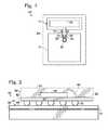
- FIG. 1shows a simplified schematic overhead view of a first example of an integrated circuit (IC) package including a die and antenna.
- ICintegrated circuit
- FIG. 2shows a schematic side view of an exemplary communication device including an IC package and printed circuit board (PCB).
- PCBprinted circuit board
- FIG. 3shows an isometric view of another exemplary communication device including an IC package with external circuit conductors.
- FIG. 4shows a bottom view of the exemplary communication device of FIG. 3 .
- FIG. 5shows a perspective view of an exemplary portable device including an inductive power receiver and IC packages with dielectric guiding structures.
- FIG. 6shows a partially exploded view of the portable device of FIG. 5 .
- FIG. 7shows the portable device of FIG. 5 facing an exemplary base unit including an inductive power source and IC packages.
- FIG. 8shows a side view of the portable device and base unit of FIG. 7 in mutual alignment.
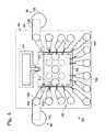
- FIG. 9shows a block diagram of unaligned exemplary first and second electronic devices each having partial shielding.
- FIG. 10shows a block diagram of aligned exemplary first and second electronic devices each having partial shielding.
- FIG. 11shows a perspective view of an exemplary connector.
- FIG. 12shows another perspective view of the exemplary connector of FIG. 11 .
- FIG. 13shows an exemplary connector proximate an exemplary external device.
- FIG. 14shows a sectional view of an exemplary connector adjacent an exemplary external device.
- FIG. 15shows a plan view of a mating surface of an exemplary connector.
- FIG. 16shows a cross-section taken along line 16 - 16 in FIG. 15 .
- FIG. 17shows a diagram of an exemplary adapter system.
- Wireless communicationmay be used to provide signal communications between components on a device or may provide communication between devices. Wireless communication provides an interface that is not subject to mechanical and electrical degradation. Examples of systems employing wireless communication between chips are disclosed in U.S. Pat. No. 5,621,913 and U.S. Published Patent Application No. 2010/0159829, the disclosures of which are incorporated herein by reference in their entirety for all purposes.
- tightly-coupled transmitter/receiver pairsmay be deployed with a transmitter disposed at a terminal portion of a first conduction path and a receiver disposed at a terminal portion of a second conduction path.
- the transmitter and receivermay be disposed in close proximity to each other depending on the strength of the transmitted energy, and the first conduction path and the second conduction path may not be contiguous with respect to each other.
- the transmitter and receivermay be disposed on separate circuit carriers positioned with the antennas of the transmitter/receiver pair in close proximity.
- a transmitter and/or receivermay be configured as an IC package, in which one or more antennas may be positioned adjacent to a die and held in place by a dielectric or insulating encapsulation or bond material. An antenna may also be held in place by a lead frame substrate. Examples of EHF antennas embedded in IC packages are shown in the drawings and described below. Note that IC packages may also be referred to as simply packages, and are examples of wireless communication units that are also variously referred to as EHF communication units, communication units, communication devices, comm-link chips, comm-link chip assemblies, comm-link chip packages, and/or comm-link packages, which may be configured in various ways.
- IC packages, communication units, communication devices, comm-link chips, comm-link chip assemblies, comm-link chip packages, and/or comm-link packagesmay each include one or more ICs, chips, or dies and have circuit functionality appropriate for particular applications.
- FIG. 1shows an exemplary IC package, generally indicated at 10 .
- IC package 10includes a chip or die 12 , a transducer 14 providing conversion between electrical and electromagnetic (EM) signals, and conductive connectors 16 , such as bond wires 18 , 20 electrically connecting the transducer to bond pads 22 , 24 connected to a transmitter or receiver circuit included in die 12 .
- IC package 10further includes an encapsulating material 26 formed around at least a portion of the die and/or the transducer. In this example encapsulating material 26 covers die 12 , conductive connectors 16 , and transducer 14 , and is shown in phantom lines so that details of the die and transducer may be illustrated in solid lines.
- Die 12includes any suitable structure configured as a miniaturized circuit on a suitable die substrate, and is functionally equivalent to a component also referred to as a chip or an integrated circuit (IC).
- a die substratemay be any suitable semiconductor material; for example, a die substrate may be silicon.
- Die 12may have a length and a width dimension, each of which may be about 1.0 mm to about 2.0 mm, and preferably about 1.2 mm to about 1.5 mm. Die 12 may be mounted with further electrical conductors 16 , such as a lead frame, not shown in FIG. 1 , providing connection to external circuits.
- a transformer 28shown in dashed lines, may provide impedance matching between a circuit on die 12 and transducer 14 .
- Transducer 14may be in the form of a folded dipole or loop antenna 30 , may be configured to operate at radio frequencies such as in the EHF spectrum, and may be configured to transmit and/or receive electromagnetic signals.
- Antenna 30is separate from but operatively connected to die 12 by suitable conductors 16 , and is located adjacent to die 12 .
- a loop configuration of antenna 30includes a 0.1 mm band of material, laid out in a loop 1.4 mm long and 0.53 mm wide, with a gap of 0.1 mm at the mouth of the loop, and with the edge of the loop approximately 0.2 mm from the edge of die 12 .
- Encapsulating material 26is used to assist in holding the various components of IC package 10 in fixed relative positions.
- Encapsulating material 26may be any suitable material configured to provide electrical insulation and physical protection for the electrical and electronic components of IC package 10 .
- encapsulating material 26also referred to as insulating material, may be a mold compound, glass, plastic, or ceramic.
- Encapsulating material 26may also be formed in any suitable shape.
- encapsulating material 26may be in the form of a rectangular block, encapsulating all components of IC package 10 except the unconnected ends of conductors 16 connecting the die to external circuits. External connections may be formed with other circuits or components.
- FIG. 2shows a representational side view of a communication device 50 including an IC package 52 flip-mounted to an exemplary printed circuit board (PCB) 54 .
- IC package 52includes a die 56 , a ground plane 57 , an antenna 58 , bond wires, including bond wire 60 , connecting the die to the antenna.
- the die, antenna, and bond wiresare mounted on a package substrate 62 and encapsulated in encapsulating material 64 .
- Ground plane 57may be mounted to a lower surface of die 56 , and may be any suitable structure configured to provide an electrical ground for the die.
- PCB 54may include a top dielectric layer 66 having a major face or surface 68 .
- IC package 52is flip-mounted to surface 68 with flip-mounting bumps 70 attached to a metallization pattern (not shown).
- PCB 54may further include a layer 72 spaced from surface 68 made of conductive material forming a ground plane within PCB 54 .
- the PCB ground planemay be any suitable structure configured to provide an electrical ground to circuits and components on PCB 54 .
- FIGS. 3 and 4illustrate another exemplary communication device 80 including an IC package 82 with external circuit conductors 84 and 86 .
- IC package 82may include a die 88 , a lead frame 90 , conductive connectors 92 in the form of bond wires, an antenna 94 , encapsulating material 96 , and other components not shown to simplify the illustration.
- Die 88may be mounted in electrical communication with lead frame 90 , which may be any suitable arrangement of electrical conductors or leads 98 configured to allow one or more other circuits to operatively connect with die 90 .
- Antenna 94may be constructed as a part of the manufacturing process that produces lead frame 90 .
- Leads 98may be embedded or fixed in a lead frame substrate 100 , shown in phantom lines, corresponding to package substrate 62 .
- the lead frame substratemay be any suitable insulating material configured to substantially hold leads 98 in a predetermined arrangement. Electrical communication between die 88 and leads 98 of lead frame 90 may be accomplished by any suitable method using conductive connectors 92 .
- conductive connectors 92may include bond wires that electrically connect terminals on a circuit of die 88 with corresponding lead conductors 98 .
- a conductor or lead 98may include a plated lead 102 formed on an upper surface of lead frame substrate 100 , a via 104 extending through the substrate, a flip-mounting bump 106 mounting IC package 82 to a circuit on a base substrate, such as a PCB, not shown.
- the circuit on the base substratemay include external conductors, such as external conductor 84 , which for example, may include a strip conductor 108 connecting bump 106 to a further via 110 extending through the base substrate.
- Other vias 112may extend through the lead frame substrate 100 and there may be additional vias 114 extending through the base substrate.
- die 88may be inverted and conductive connectors 92 may include bumps, or die solder balls, as described previously, which may be configured to electrically connect points on a circuit of die 88 directly to corresponding leads 98 in what is commonly known as a “flip chip” arrangement.
- a first and a second IC package 10may be co-located on a single PCB and may provide intra-PCB communication.
- a first IC package 10may be located on a first PCB and a second IC package 10 may be located on a second PCB and may therefore provide inter-PCB communication.
- a portable device 120may be any device configured to be powered wirelessly using an inductive power system and also to communicate wirelessly using one or more IC packages 10 .
- Portable device 120may include an EHF communication circuit 122 , a data storage unit 124 , local power storage device 126 , and/or inductive power receiver 128 .
- the components of portable device 120may be contained in a case (not shown).
- FIGS. 5 and 6depict an example of a portable device 120 showing possible locations of various components.
- FIG. 6is a partially exploded version of the device shown in FIG. 5 .
- a portable devicemay also be a portable media device (pmd), which may take the form of a cell phone, personal digital assistant (pda), MP3 players, notebook computer, or tablet.
- pmdportable media device
- EHF communication circuit 122may be any circuit configured to communicate wirelessly using one or more IC packages 10 .
- EHF communication circuit 122may include two IC packages 130 and 132 , one configured as a transmitter and the other configured as a receiver as depicted in FIGS. 5 and 6 .
- IC packages 130 and 132may be configured to communicate with other IC packages in other devices rather than with other such chips in the same device. In some examples, only one IC package may be included, with the IC package configured as a transceiver.
- EHF communication circuit 122may be in electrical communication with digital data storage unit 124 .
- Data storage unit 124may be any suitable data storage unit capable of reading and writing data.
- data storage unit 124may be an IC chip, card, disk, or SSD.
- EHF communication circuit 122may transfer data between data storage unit 124 and an external device.
- EHF communication circuit 122may also receive power from local power storage device 126 .
- Power storage device 126may be any suitable device configured to store electrical energy for future use.
- power storage device 126may be a lithium ion battery, a fuel cell, an ultracapacitor, or any other battery-like device that may be charged and discharged.
- the voltage supplied by such a devicemay need to be stepped down using suitable circuitry in EHF communication circuit 122 to make the voltage usable by the circuit and IC packages.
- IC packagessuch as IC package 130 and 132 typically operate in the approximate range of 1.2 to 3.3 V.
- Inductive power receiver 128may be in electrical communication with local power storage device 126 and may function to charge power storage device 126 .
- Inductive power receiver 128may be any suitable device capable of receiving wireless energy transfer from a power source.
- inductive power receiver 128may include a secondary coil 129 in which a current may be induced by a primary coil located in a separate charging device.
- Worldwide open standards for this sort of inductive charginghave been developed. For example the “Qi” standard developed by the Wireless Power Consortium has begun to be utilized in commercial products.
- the illustrative portable device 120 in FIGS. 5 and 6may further include conductive suppressor 134 , dielectric isolation barrier 136 , and dielectric directing portion 138 .
- Conductive suppressor 134may be any suitable structure configured to suppress ingress or egress of spurious EHF radiation.
- suppressor 134may be constructed as an expanse of conductive material disposed laterally around dielectric isolation barrier 136 .
- Dielectric isolation barrier 136may be any suitable structure or gap configured to isolate dielectric directing portion 138 from suppressor 134 .
- dielectric isolation barrier 136may be a low-E r dielectric such as foam, or may be an air gap laterally surrounding dielectric directing portion 138 .
- Dielectric directing portion 138may be any suitable dielectric structure configured to enhance and/or direct EHF radiation.
- dielectric directing portion 138may be a block of high-E r material such as plastic.
- a portable device such as portable device 120may function independently (e.g., as a portable media device), and may interact and/or receive power from other devices.
- a base unitmay be one such device.
- a base unit 140may be any suitable device configured to wirelessly communicate with portable device 120 and to wirelessly provide power to portable device 120 .
- base unit 140may include a housing (not shown) that encloses an inductive power source 142 and/or an EHF communications circuit 144 .
- base unit 140may include or be in communication with a host controller (not shown), which may be any suitable device or component configured to control the electronic activity of an overall system including portable device 120 and base unit 140 .
- a host controllermay be a personal computing device configured via software and/or firmware to coordinate synchronization of data between portable device 120 and a personal computer.
- a host controllermay include any or all of the following: a video player; audio player; security system; display system; music, video, and/or audiobook organizer; data back-up storage system; portable phone manager; etc.
- a host controllermay be located in portable device 120 and base unit 140 may include a storage unit such as storage unit 124 .
- both devicesmay include host controller and/or storage unit 124 , enabling functionality such as device-to-device data copying.
- portable device 120may control a transaction wherein a video playing or available on portable device 120 may appear on a base unit 140 that includes a video display. This transaction may be controlled entirely from the portable device.
- Inductive power source 142may be any suitable device configured to provide electrical power wirelessly to inductive power receiver 128 . As described above, inductive power source 142 may include primary coil 146 .
- EHF communications circuit 144may include one or more IC packages 10 , such as IC packages 148 and 150 , configured to transfer information to and from the IC package(s) in portable device 120 .
- IC packagesmay be configured as transceivers, and each two-way link may be established using one IC package per device.
- the resulting transmitter-receiver or transceiver-transceiver pairsmay be disposed such that proper general alignment of the devices also aligns all pairs of IC packages.
- some transmitter-receiver or transceiver-transceiver pairsmay be aligned when the devices are placed in a first configuration while others may be aligned when the devices are placed in a second configuration.
- a base unit 140may provide two sets of markings on an interface surface. One set of markings may indicate where to place portable device 120 to enable data synchronization, while the other may indicate where to place portable device 120 to enable music playback or some other functionality, and both positions may allow simultaneous battery charging.
- FIGS. 7 and 8show portable device 120 and a base unit 140 .
- inductive power source 142 and IC packages 148 and 150may be disposed and configured in a spatial arrangement complementary to the corresponding components in portable device 120 .
- FIG. 8further illustrates this complementary arrangement, depicting a portable device 120 in docking alignment with base unit 140 .
- each devicemay include a single IC package configured as a transceiver rather than two IC packages respectively configured as a transmitter and receiver.
- EHF signalsthat may be transmitted and received between devices such as portable device 120 and base unit 140
- governmental emissions limitsmay exist for a given licensed emissions band. It is noted that an unmodulated signal may provide a narrower band of emissions, thereby avoiding violation of an emissions limit in some applications. On the other hand, a modulated signal may produce a broader band of emissions that in some applications may extend outside the licensed band.
- FIGS. 9 and 10are block diagrams showing two exemplary devices configured to limit the production of emissions which may extend outside of a given band.
- a portion of a first electronic device 160may include two examples of IC packages 10 , specifically a transmitter 162 and a receiver 164 , electrically connected to a baseband modulation circuit 169 .
- a discontinuous shield 168may partly surround IC packages 162 and 164 .
- a portion of first electronic device 160may include a layer or section of material that acts to inhibit or block EHF signals.
- Shield 168may include any suitable material configured to inhibit or block electromagnetic signals having an EHF frequency.
- a grounded electromagnetically conductive materialmay drain an EHF signal to ground, and a dissipative material may absorb an EHF signal and convert it to heat within the material.
- This shielding layer or sectionmay be discontinuous in the sense that it does not form a continuous shield in every direction, but rather includes an opening or openings in one or more directions.
- the partial shielding configurationis represented in FIGS. 9 and 10 as a U-shaped cross section.
- shield 168may be configured to facilitate a mating relationship with a corresponding shield on another device.
- Transmitter chip 162may be an example of the previously described IC package 10 , and may be adapted to transmit an EHF signal provided by one or more circuits in device 160 in upstream series with baseband modulation circuit 169 .
- transmitter chip 162may transmit a substantially constant signal, a modulated signal, an intermittent signal, a combination of these, or any other signal capable of being transmitted in the EHF band.
- Receiver chip 164may also be an example of the previously described IC package 10 , and may be adapted to receive an EHF signal and to provide that signal in electronic form to one or more circuits in first device 160 , including baseband modulation circuit 169 . Note that transmitter and receiver packages 162 and 164 may be replaced in some examples by a single transceiver package configured to both transmit and receive.
- Baseband modulation circuit 169may be any suitable circuit configured to select between two or more signals based on one or more inputs.
- baseband modulation circuit 169may include a multiplexer circuit adapted to receive inputs from transmitter chip 162 , receiver chip 164 , a modulated signal generator, and one or more signal generating circuits, such as an unmodulated signal generator.
- a second electronic device 176may be similar to first device 160 , and may include a transmitter chip 178 , a receiver chip 180 , a baseband modulation circuit 185 , and a shield 184 with similar functions and connections as the corresponding components of first device 160 .
- devices 160 and 176may be physically moved from a misaligned to an aligned relationship.
- alignmentrefers to axial and proximal alignment of the transmitter-receiver pairs, namely transmitter 162 and receiver 180 as well as transmitter 178 and receiver 164 . In other examples, these may be replaced by a suitable transceiver-transceiver pair. Proper alignment of these pairs may allow EHF signal communication between at least one of the pairs and thus communication between the first and second devices.
- the shields of devices 160 and 176may also be configured to ensure that the shields are aligned when the transmitter-receiver or transceiver-transceiver pairs are in proper alignment.
- discontinuous shield 168 and discontinuous shield 184may be configured as mates, capable of forming a single continuous shield around the pairs of IC packages when the shields are placed in an aligned and mated position.
- Connector 200may be any suitable connector component configured to provide a zero- or low-insertion EHF connection interface for a corresponding connector component on another device or system.
- Connector 200may include two magnets, 202 and 204 , a connector PCB 206 , two IC packages 10 , labeled as 208 and 210 , a connector body 212 , and/or a connector alignment portion 214 .
- connector 200may be electrically and physically connected to a cable 216 .
- Connector body 212may serve as a housing or container for other components of connector 200 .
- connector body 212may encapsulate PCB 206 and IC packages 208 and 210 using a suitable dielectric material or materials.
- Connector body 212may also be sized and configured to allow convenient manipulation by a user.
- Magnets 202 and 204may be at least partially housed in connector body 212 , and may be mounted such that both magnets are substantially flush with a mating surface 218 of connector body 212 .
- Mating surface 218may be configured to provide a suitable physical coupling surface with a corresponding connector on a corresponding device. In some examples, mating surface 218 is planar. In other examples, mating surface 218 is curved. In still other examples, mating surface 218 includes alignment portion 214 . Alignment portion 214 may be a protrusion, ridge, knob, bevel, pin, recess, or other member configured to mate with a corresponding portion on a corresponding target connection region 220 of an external device 222 , as shown in FIG. 13 , to provide physical alignment feedback to a user.
- Magnets 202 and 204may be any suitable magnetic components configured to releasably hold connector 200 in aligned proximity to target connection region 220 of external device 222 .
- alignment and proximitymay refer to the alignment and proximity of corresponding IC packages, which may need to be substantially aligned and in close enough proximity to enable communication between a given pair of packages.
- magnets 202 and 204are permanent magnets.
- magnets 202 and 204are electromagnets.
- magnets 202 and 204are constructed of ferrous material capable of being magnetically attracted to magnets on or near target connection region 220 .
- IC packages 208 and 210may be mounted on connector PCB 206 . In some examples, more or fewer packages, assemblies, or chips may be provided. IC packages 208 and 210 may be mounted on PCB 206 such that an antenna of IC package 208 is oriented orthogonally to an antenna of IC package 210 , to take advantage of polarization effects. In other words, orthogonal orientation may allow the packages to be mounted closely together, because orthogonal EHF signals will not substantially interfere with each other.
- Connector PCB 206 and related circuitsmay be electrically connected to cable 216 to allow connector 200 to obtain power and/or informational signals from a source outside of connector 200 .
- cable 216may provide connector 200 with electrical power as well as providing a data signal path to and/or from a personal computer or other host device.
- FIG. 13shows a connector 200 in close proximity to an illustrative external device 222 .
- external device 222may include an external device PCB 224 with two IC packages 226 and 228 disposed near an edge 230 of the external device.
- IC packages 226 and 228may be provided.
- Target connection region 220 at edge 230may include portions made of ferrous material or any other material that provides a magnetically attractive surface to which magnets 202 and 204 may attach.
- placing connector 200 near target connection region 220 of external device 222may cause magnets 202 and 204 to be attracted to target connection region 220 , pulling connector 200 into proper position and alignment to allow IC packages 208 and 210 to align and communicate with IC packages 226 and 228 .
- connector body 212may include a first dielectric material 232 at least partially surrounding IC package 208 and/or 210 (shown in FIG. 14 as IC package 208 for convenience) and a second dielectric material 234 at least partially surrounding first dielectric material 232 .
- First dielectric material 232may have a relatively high dielectric constant compared to second dielectric material 234 .
- dielectric material 232may include plastic with a dielectric constant of approximately 2 to approximately 5, while dielectric material 234 may include a substance with a relatively much lower constant.
- dielectric material 234may include foam or an air gap.
- First dielectric material 232may be configured as a volume of material spanning the region from IC package 208 to mating surface 218 of connector 200 .
- This architecturewith a higher dielectric constant material surrounded by a lower dielectric constant material, may facilitate focusing and shaping of a transmitted EHF signal through dielectric material 232 .
- a corresponding high-dielectric material 236may be included spanning from target connection region 220 at a surface of external device 222 to one or more IC packages 238 within in the external device.
- aligning connector 200 in close proximity with target connection region 220creates a path of substantially continuous dielectric material through which an EHF signal can propagate from package 208 to package 238 .
- FIGS. 15 and 16depict two views of a connector 250 , which may be an example of a connector 200 incorporating partial shielding similar to that described with respect to FIGS. 9 and 10 .
- FIG. 16is a cross-section taken along line 16 - 16 of FIG. 15 .
- connector 250may include two magnets 252 and 254 , a PCB 256 , two IC packages 258 and 260 , and a body 262 , with a first dielectric material 264 proximate the IC packages and a second dielectric material 266 having a lower dielectric constant surrounding first dielectric material 264 .
- shielding material 268may be provided in at least a portion of a connector body 262 .
- Shielding material 268may include any dissipative or electrically conductive material or layer configured to absorb or otherwise block spurious incoming and outgoing EHF radiation.
- shielding material 268may include a copper sheet or layer wrapping around the IC packages and leaving at least a portion of a mating surface 270 unshielded.
- shielding material 268may provide an electrical circuit ground for one or more circuits in connector 250 .
- FIG. 17is a simplified diagram depicting a side cut-out view of an exemplary adapter 280 incorporating some of the components described above.
- Adapter 280may be any suitable system configured to adapt an IC package-enabled external device 282 to be used with a standard mechanical or physical plug-type connector.
- Adapter 280may include adapter sleeve 284 , a female connector element 286 , an IC package 288 , and a dielectric and shielding architecture 290 .
- Adapter sleeve 284may be a housing for the adapter and may also fit closely around at least a portion of external device 282 , aligning an IC package 292 of the external device with IC package 288 .
- adapter sleeve 284may be configured as a partial case for the device.
- IC package 288may align and communicate with IC package 292 in the external device when sleeve 284 is attached to device 282 .
- IC package 288may also be in electrical communication with female connector element 286 .
- Female connector element 286may present a standard plug-in connector interface to a corresponding male connector element 294 of a physical plug-type connector.
- IC package 288may be embedded in or surrounded by a dielectric and shielding architecture 290 similar to architectures described above.
- Architecture 290may include a high-dielectric constant material 296 surrounding IC package 288 , material 296 being at least partially surrounded by a low-dielectric constant material 298 as well as a shielding material or layer 300 , as depicted in FIG. 17 .
- Communication of an EHF signal between IC packages 288 and 292may be facilitated by architecture 290 .
- a signalmay also be communicated between IC package 288 and male connector element 294 through female connector element 286 , as described above.
- adapter 280may adapt between a physical connector system and an IC package-enabled, physical-connectorless external device 282 .
- a system, device, or method as described above for providing wireless power and data transfermay include one or more of the following examples.
- an electronic devicemay include a first dielectric substrate, at least a first electronic circuit supported by the substrate, for processing data, and at least a first communication unit having a first antenna.
- the first communication unitmay be mounted to the substrate in communication with the at least a first electronic circuit for converting between a first EHF electromagnetic signal containing digital information and a first data signal conducted by the at least a first electronic circuit.
- the first electromagnetic signalmay be transmitted or received along a first signal path by the first antenna.
- a first electromagnetic (EM) signal guide assemblymay include a first dielectric element made of a first dielectric material disposed proximate the first antenna in the first signal path.
- the first EM signal guidemay have sides extending along the first signal path.
- a first sleeve elementmay extend around the first dielectric element along at least a portion of the sides of the first dielectric element. The first sleeve element may impede transmission of the first EM signal through the sides of the first dielectric element.
- the first sleeve elementmay be made of one or more of an electrically conductive material, an electromagnetically absorptive material, an electromagnetically dissipative material, and a second dielectric material having a dielectric constant that is lower than a dielectric constant of the first dielectric element.
- the first sleeve elementmay be made of the second dielectric material and may have sides extending along the signal path corresponding to the sides of the first dielectric element.
- the signal guidemay include a second sleeve element disposed around the sides of the first sleeve element, and may be made of the electromagnetically dissipative material.
- the first communication unitmay be a transceiver.
- the at least a first communication unitmay include a second communication unit having a second antenna.
- the second communication unitmay be mounted to the substrate in communication with the at least a first electronic circuit for converting between a second EHF EM signal containing digital information and a second data signal conducted by the at least a first electronic circuit.
- the second electromagnetic signalmay be transmitted or received along a second signal path by the second antenna.
- the electromagnetic signal guide assemblymay further include a second dielectric element made of a third dielectric material disposed proximate the second antenna in the second signal path and having sides extending along the second signal path.
- a second sleeve elementmay extend around the second dielectric element along at least a portion of the sides of the second dielectric element. The second sleeve element may impede transmission of the second electromagnetic signal through the sides of the second dielectric element.
- the second sleeve elementmay be made of a fourth dielectric material having a dielectric constant that is lower than a dielectric constant of the second dielectric element.
- the second sleeve elementmay have sides extending along the second signal path corresponding to the sides of the second dielectric element.
- the signal guide assemblymay further include a sleeve assembly disposed around the sides of the first and second sleeve elements, extending continuously between the first and second sleeve elements, and being made of an electrically conductive material.
- the first communication unitmay be a transmitter and the second communication unit may be a receiver.
- An electronic systemmay include the first electronic device and a second electronic device including a second dielectric substrate, at least a second electronic circuit supported by the second substrate, for processing data, and at least a second communication unit having a second antenna.
- the second communication unitmay be mounted to the second substrate in communication with the at least a second electronic circuit for converting between a second EHF EM signal containing digital information and a second data signal conducted by the at least a second electronic circuit.
- the second EM signalmay be transmitted or received along a second signal path by the second antenna.
- a second EM signal guide assemblymay include a second dielectric element made of a second dielectric material disposed proximate the second antenna in the second signal path and having sides extending along the second signal path.
- a second sleeve elementmay extend around the second dielectric element along at least a portion of the sides of the second dielectric element. The second sleeve element may impede transmission of the second electromagnetic signal through the sides of the second dielectric element.
- the first communication unitmay be a transmitter
- the second communication unitmay be a receiver configured to communicate with the first communication unit when the first guide assembly is positioned proximate to and facing the second guide assembly.
- the first and second dielectric elementsmay have corresponding dimensions transverse to the respective first and second signal paths.
- the first sleeve elementmay align with the second sleeve element and the first and second sleeve elements in combination may impede transmission of the first electromagnetic signal through the sides of the first and second dielectric elements.
- the first and second sleeve elementsmay be made of a material that form in combination an electrical, magnetic, or electromagnetic shield extending along the first and second dielectric elements when the first sleeve element is placed against the second sleeve element.
- the first and second dielectric elements of the two guide assembliesmay have same cross-section dimensions, and the first and second sleeve elements may extend behind the respective first and second communication units.
- a first electronic connector elementmay include a first EHF comm-link chip, a first dielectric material encasing the first comm-link chip and extending from the first chip toward a first interface surface spaced from the first comm-link chip.
- the first comm-link chipmay be configured to transmit or receive an electromagnetic signal having a first signal path extending through the dielectric material and the first interface surface.
- a shielding materialmay be supported by the dielectric material and may extend from a first side of the first interface surface around the first comm-link chip opposite the first interface surface to a second side of the first interface surface spaced from the first side of the first interface surface.
- the shielding materialmay be made of one or more of an electrically conductive material, an electromagnetically absorptive material, and an electromagnetically dissipative material.
- the shielding materialmay form a continuous loop around the interface surface.
- the shielding materialmay be connected to a circuit ground of the first comm-link chip.
- the shielding materialmay be configured to substantially absorb and dissipate EHF radiation that reaches the shielding material from the electromagnetic signal.
- a systemmay include first electronic connector element and a second electronic connector element.
- the first electronic connector elementmay further include a first mating element forming at least a portion of the first interface surface.
- the second electronic connector elementmay include a second EHF comm-link chip, a second mating surface spaced from the second comm-link chip, and a second mating element forming at least a portion of a second interface surface.
- the second comm-link chipmay be configured to transmit or receive an electromagnetic signal having a second signal path extending through the second interface surface.
- the first and second mating elementsbeing complementary and including a combination of a recess formed in one of the first and second interface surfaces and a protrusion formed in the other of the first and second interface surfaces, the protrusion being configured to be received in the recess when the first and second interface surfaces are placed in close proximity to each other.
- the first and second comm-link chipsmay be configured to communicate an EHF signal between the first electronic connector element and the second electronic connector element.
- the first electronic connector elementmay further include a second dielectric material at least partially surrounding the first dielectric material transverse to the first signal path,
- the first dielectric materialmay have a dielectric constant that is substantially higher than a dielectric constant of the second dielectric material.
- the first comm-link chip of the first electronic connectormay include an integrated circuit (IC), an antenna in communication with the IC, and an insulating material holding the IC and antenna in a fixed location.
- ICintegrated circuit
- the first dielectric material of the first electronic connector elementmay have a dielectric constant between about 2 and about 5.
- a systemmay include a first device and a second device.
- the first devicemay include a first electrical circuit and a first electronic connector component having a first dielectric material.
- a first EHF comm-link chipmay be embedded in the first dielectric material and connected to the first electrical circuit for communicating a first electromagnetic signal that propagates along a first signal path passing through the first dielectric material.
- An electrically conductive shielding layermay extend around at least a portion of the first signal path in the first dielectric material.
- the second devicemay include a second electrical circuit and a second electronic connector component having a second dielectric material and a second EHF comm-link chip embedded in the second dielectric material and connected to the second electrical circuit for communicating a second electromagnetic signal that propagates along a second signal path passing through the second dielectric material.
- the first and second EHF comm-link chipsmay be configured to communicate with each other when the first and second electronic connector components are positioned with the first dielectric material in contact with the second dielectric material with the first signal path aligned with the second signal path. Communication along the first and second signal paths may occur substantially entirely through the first dielectric material and the second dielectric material.
- the electrically conductive shielding layermay be electrically conductive and may be connected to a circuit ground for the first electrical circuit.
- the electrically conductive shielding layermay be configured to substantially absorb and dissipate EHF electromagnetic radiation.
- a fourth examplemay include an adapter for interconnecting a first electronic device having a first electrically conductive connector element with a second electronic device having an EHF electromagnetic signal connector element.
- the adaptermay include a dielectric material, an EHF comm-link chip embedded in the dielectric material and configured to communicate the electromagnetic signal with the electromagnetic signal connector element, and a second electrically conductive connector element electrically connected to the comm-link chip and configured to electrically connect to the first electrically conductive connector element.
- the adaptermay further include a sleeve forming a channel.
- the comm-link chipmay be disposed at a first end of the channel.
- the sleevemay be sized and configured to receive the electromagnetic signal connector element.
- a systemmay include a first device and a second device.
- the first devicemay include a first EHF comm-link chip assembly configured to transmit a first EHF electromagnetic signal, a first shield partly surrounding the first EHF comm-link chip assembly, and a first circuit in communication with the first EHF comm-link chip assembly.
- the second devicemay have a second EHF comm-link chip assembly configured to receive the first EHF electromagnetic signal and a second shield partly surrounding the second EHF comm-link chip assembly.
- the first and second shieldsmay be configured mutually to create a substantially continuous shield around the first and second EHF comm-link chip assemblies when the first and second devices are aligned.
- the first EHF comm-link chip assemblymay be in communication with the first circuit and configured to receive a second EHF electromagnetic signal when the first and second devices are aligned.
- the second devicemay further include a second circuit, the second EHF comm-link chip assembly being in communication with the second circuit and configured to transmit the second EHF electromagnetic signal.
- the first and second devicesmay be configured such that alignment of the devices results in substantial alignment of the first and second EHF comm-link chip assemblies, and substantial alignment of the first and second EHF comm-link chip assemblies includes both lateral and proximal alignment sufficient to enable adequate signal communication between the first and second EHF comm-link chip assemblies.
- the first EHF comm-link chip assemblymay include insulating material, an integrated circuit (IC), and an antenna that communicates with the IC and is fixed in location relative to the IC by the insulating material.
- ICintegrated circuit
- the inventions described hereinrelate to industrial and commercial industries, such as electronics and communications industries using devices that communicate with other devices or devices having communication between components in the devices.
Landscapes
- Engineering & Computer Science (AREA)
- Microelectronics & Electronic Packaging (AREA)
- Physics & Mathematics (AREA)
- Power Engineering (AREA)
- Condensed Matter Physics & Semiconductors (AREA)
- General Physics & Mathematics (AREA)
- Computer Hardware Design (AREA)
- Computer Networks & Wireless Communication (AREA)
- Signal Processing (AREA)
- Toxicology (AREA)
- Electromagnetism (AREA)
- Health & Medical Sciences (AREA)
- Near-Field Transmission Systems (AREA)
- Variable-Direction Aerials And Aerial Arrays (AREA)
- Details Of Aerials (AREA)
Abstract
Description
Claims (28)
Priority Applications (5)
| Application Number | Priority Date | Filing Date | Title |
|---|---|---|---|
| US13/618,138US8909135B2 (en) | 2011-09-15 | 2012-09-14 | Wireless communication with dielectric medium |
| US14/533,545US9787349B2 (en) | 2011-09-15 | 2014-11-05 | Wireless communication with dielectric medium |
| US15/360,647US10027018B2 (en) | 2011-09-15 | 2016-11-23 | Wireless communication with dielectric medium |
| US15/988,957US10381713B2 (en) | 2011-09-15 | 2018-05-24 | Wireless communications with dielectric medium |
| US16/450,790US10707557B2 (en) | 2011-09-15 | 2019-06-24 | Wireless communication with dielectric medium |
Applications Claiming Priority (4)
| Application Number | Priority Date | Filing Date | Title |
|---|---|---|---|
| US201161535277P | 2011-09-15 | 2011-09-15 | |
| US201161570709P | 2011-12-14 | 2011-12-14 | |
| US201261592491P | 2012-01-30 | 2012-01-30 | |
| US13/618,138US8909135B2 (en) | 2011-09-15 | 2012-09-14 | Wireless communication with dielectric medium |
Related Child Applications (1)
| Application Number | Title | Priority Date | Filing Date |
|---|---|---|---|
| US14/533,545ContinuationUS9787349B2 (en) | 2011-09-15 | 2014-11-05 | Wireless communication with dielectric medium |
Publications (2)
| Publication Number | Publication Date |
|---|---|
| US20130070817A1 US20130070817A1 (en) | 2013-03-21 |
| US8909135B2true US8909135B2 (en) | 2014-12-09 |
Family
ID=47010739
Family Applications (5)
| Application Number | Title | Priority Date | Filing Date |
|---|---|---|---|
| US13/618,138Active2033-04-26US8909135B2 (en) | 2011-09-15 | 2012-09-14 | Wireless communication with dielectric medium |
| US14/533,545ActiveUS9787349B2 (en) | 2011-09-15 | 2014-11-05 | Wireless communication with dielectric medium |
| US15/360,647ActiveUS10027018B2 (en) | 2011-09-15 | 2016-11-23 | Wireless communication with dielectric medium |
| US15/988,957ActiveUS10381713B2 (en) | 2011-09-15 | 2018-05-24 | Wireless communications with dielectric medium |
| US16/450,790ActiveUS10707557B2 (en) | 2011-09-15 | 2019-06-24 | Wireless communication with dielectric medium |
Family Applications After (4)
| Application Number | Title | Priority Date | Filing Date |
|---|---|---|---|
| US14/533,545ActiveUS9787349B2 (en) | 2011-09-15 | 2014-11-05 | Wireless communication with dielectric medium |
| US15/360,647ActiveUS10027018B2 (en) | 2011-09-15 | 2016-11-23 | Wireless communication with dielectric medium |
| US15/988,957ActiveUS10381713B2 (en) | 2011-09-15 | 2018-05-24 | Wireless communications with dielectric medium |
| US16/450,790ActiveUS10707557B2 (en) | 2011-09-15 | 2019-06-24 | Wireless communication with dielectric medium |
Country Status (7)
| Country | Link |
|---|---|
| US (5) | US8909135B2 (en) |
| EP (1) | EP2759067B1 (en) |
| JP (2) | JP5844472B2 (en) |
| KR (1) | KR101879907B1 (en) |
| CN (1) | CN106330268B (en) |
| TW (2) | TWI554165B (en) |
| WO (1) | WO2013040396A1 (en) |
Cited By (9)
| Publication number | Priority date | Publication date | Assignee | Title |
|---|---|---|---|---|
| US20150065069A1 (en)* | 2011-09-15 | 2015-03-05 | Keyssa, Inc. | Wireless Communication With Dielectric Medium |
| US20150111496A1 (en)* | 2013-10-18 | 2015-04-23 | Keyssa, Inc. | Contactless communication unit connector assemblies with signal directing structures |
| US9614590B2 (en) | 2011-05-12 | 2017-04-04 | Keyssa, Inc. | Scalable high-bandwidth connectivity |
| US9900054B2 (en) | 2012-01-30 | 2018-02-20 | Keyssa, Inc. | Link emission control |
| US20180287773A1 (en)* | 2017-03-31 | 2018-10-04 | Intel Corporation | Millimeter wave cmos engines for waveguide fabrics |
| US10389454B2 (en) | 2015-12-14 | 2019-08-20 | Keyssa Systems, Inc. | Cross-talk blocking structures for EM communication |
| US20190304934A1 (en)* | 2018-03-27 | 2019-10-03 | Nxp B.V. | Multi-die and antenna array device |
| US10673780B2 (en) | 2017-12-11 | 2020-06-02 | Keyssa Systems, Inc. | Computing devices using extremely high frequency (EHF) electromagnetic communication |
| US10795102B2 (en) | 2018-01-03 | 2020-10-06 | Fuding Precision Components (Shenzhen) Co., Ltd | Interconnection system with hybrid transmission |
Families Citing this family (53)
| Publication number | Priority date | Publication date | Assignee | Title |
|---|---|---|---|---|
| US9960820B2 (en) | 2008-12-23 | 2018-05-01 | Keyssa, Inc. | Contactless data transfer systems and methods |
| US8554136B2 (en) | 2008-12-23 | 2013-10-08 | Waveconnex, Inc. | Tightly-coupled near-field communication-link connector-replacement chips |
| US9954579B2 (en) | 2008-12-23 | 2018-04-24 | Keyssa, Inc. | Smart connectors and associated communications links |
| US9474099B2 (en) | 2008-12-23 | 2016-10-18 | Keyssa, Inc. | Smart connectors and associated communications links |
| US9191263B2 (en) | 2008-12-23 | 2015-11-17 | Keyssa, Inc. | Contactless replacement for cabled standards-based interfaces |
| US8794980B2 (en) | 2011-12-14 | 2014-08-05 | Keyssa, Inc. | Connectors providing HAPTIC feedback |
| US9219956B2 (en) | 2008-12-23 | 2015-12-22 | Keyssa, Inc. | Contactless audio adapter, and methods |
| KR101615082B1 (en) | 2011-03-24 | 2016-04-29 | 키사, 아이엔씨. | Integrated circuit with electromagnetic communication |
| US8714459B2 (en) | 2011-05-12 | 2014-05-06 | Waveconnex, Inc. | Scalable high-bandwidth connectivity |
| US8811526B2 (en) | 2011-05-31 | 2014-08-19 | Keyssa, Inc. | Delta modulated low power EHF communication link |
| TWI569031B (en) | 2011-06-15 | 2017-02-01 | 奇沙公司 | Near-end sensing and distance measurement using EHF signals |
| EP2769477A1 (en) | 2011-10-20 | 2014-08-27 | Keyssa, Inc. | Low-profile wireless connectors |
| TWI562555B (en) | 2011-10-21 | 2016-12-11 | Keyssa Inc | Contactless signal splicing |
| US9344201B2 (en) | 2012-01-30 | 2016-05-17 | Keyssa, Inc. | Shielded EHF connector assemblies |
| CN107276641B (en) | 2012-03-02 | 2021-07-02 | 凯萨股份有限公司 | Duplex communication system and method |
| CN104303436B (en) | 2012-03-06 | 2017-04-05 | 凯萨股份有限公司 | System for constraining operating parameters of an EHF communication chip |
| EP2832192B1 (en) | 2012-03-28 | 2017-09-27 | Keyssa, Inc. | Redirection of electromagnetic signals using substrate structures |
| CN104321930A (en) | 2012-04-17 | 2015-01-28 | 凯萨股份有限公司 | Dielectric lens structures for interchip communication |
| EP2883271B1 (en) | 2012-08-10 | 2020-07-22 | Keyssa, Inc. | Dielectric coupling systems for ehf communications |
| US9374154B2 (en) | 2012-09-14 | 2016-06-21 | Keyssa, Inc. | Wireless connections with virtual hysteresis |
| WO2014100058A1 (en) | 2012-12-17 | 2014-06-26 | Waveconnex, Inc. | Modular electronics |
| US9325384B2 (en)* | 2013-03-15 | 2016-04-26 | Keyssa, Inc. | Misalignment-tolerant high-density multi-transmitter/receiver modules for extremely-high frequency (EHF) close-proximity wireless connections |
| TWI551093B (en) | 2013-03-15 | 2016-09-21 | 奇沙公司 | Extremely high frequency communication chip |
| EP2974058B1 (en) | 2013-03-15 | 2020-07-15 | Keyssa, Inc. | Contactless ehf data communication |
| KR20150132459A (en) | 2013-03-15 | 2015-11-25 | 키사, 아이엔씨. | Ehf secure communication device |
| US9407731B2 (en) | 2013-05-16 | 2016-08-02 | Keyssa, Inc. | Extremely high frequency converter |
| WO2015023781A2 (en) | 2013-08-13 | 2015-02-19 | Keyssa, Inc. | Contactless communication unit connector assemblies |
| EP2863473B1 (en)* | 2013-10-16 | 2019-03-20 | Airbus Defence and Space GmbH | Space-Borne Antenna System |
| WO2015116597A1 (en)* | 2014-01-28 | 2015-08-06 | Team Oil Tools, Lp | Method and apparatus for downhole tool actuation |
| US9602648B2 (en) | 2015-04-30 | 2017-03-21 | Keyssa Systems, Inc. | Adapter devices for enhancing the functionality of other devices |
| US9947983B2 (en)* | 2015-08-05 | 2018-04-17 | Keyssa, Inc. | Contactless signal conduit structures |
| US20170110787A1 (en) | 2015-10-14 | 2017-04-20 | Apple Inc. | Electronic Devices With Millimeter Wave Antennas And Metal Housings |
| US10049801B2 (en)* | 2015-10-16 | 2018-08-14 | Keyssa Licensing, Inc. | Communication module alignment |
| US10455375B2 (en) | 2015-11-21 | 2019-10-22 | Nanoport Technology Inc. | Controlling access to a hardware resource of an electronic device by a magnetically attachable electronic device |
| US10498379B2 (en) | 2015-12-08 | 2019-12-03 | Intel Corporation | Wireless interconnects on flexible cables between computing platforms |
| US10547339B2 (en) | 2016-01-29 | 2020-01-28 | Apple Inc. | Electronic devices having millimeter wave wireless data transfer capabilities |
| US9684612B1 (en) | 2016-02-02 | 2017-06-20 | Nanoport Technology Inc. | Mobile device capable of determining spatial relationships and methods |
| US10772192B2 (en)* | 2016-05-03 | 2020-09-08 | Keyssa Systems, Inc. | Board-to-board contactless connectors and methods for the assembly thereof |
| US10615489B2 (en)* | 2016-06-08 | 2020-04-07 | Futurewei Technologies, Inc. | Wearable article apparatus and method with multiple antennas |
| US10250418B2 (en) | 2016-08-02 | 2019-04-02 | Keyssa Systems, Inc. | EHF receiver architecture with dynamically adjustable discrimination threshold |
| WO2018141064A1 (en)* | 2017-02-03 | 2018-08-09 | Nanoport Technology Inc. | Multi-device video and audio |
| US10469112B2 (en)* | 2017-05-31 | 2019-11-05 | Silicon Laboratories Inc. | System, apparatus and method for performing automatic gain control in a receiver for a packet-based protocol |
| US10348871B2 (en)* | 2017-07-03 | 2019-07-09 | Essential Products, Inc. | Transmission stack for extremely high frequency wireless communication |
| US10462345B2 (en) | 2017-08-11 | 2019-10-29 | Essential Products, Inc. | Deformable structure that compensates for displacement of a camera module of a camera accessory |
| CN107565919B (en)* | 2017-08-21 | 2020-11-17 | 南京理工大学 | S-band isolation amplifier with integrated packaging structure |
| TWI673510B (en)* | 2018-07-17 | 2019-10-01 | 昇雷科技股份有限公司 | Doppler radar with bondwire interconnection structure |
| WO2020206625A1 (en)* | 2019-04-10 | 2020-10-15 | Intel Corporation | Resilient electrical connectors for electromagnetic interference shielding structures in integrated circuit assemblies |
| US11177553B2 (en)* | 2019-05-03 | 2021-11-16 | Qualcomm Incorporated | Interface connector for supporting millimeter wave wireless communications |
| US11094652B1 (en)* | 2020-07-24 | 2021-08-17 | Realtek Semiconductor Corp. | Configurable radio transceiver and method thereof |
| JP7638662B2 (en)* | 2020-10-22 | 2025-03-04 | キヤノン株式会社 | Wireless transmission system, control method, and program |
| CN215869946U (en) | 2021-08-05 | 2022-02-18 | 东莞富强电子有限公司 | Magnetic connector |
| US12374799B2 (en)* | 2021-11-22 | 2025-07-29 | Samsung Electronics Co., Ltd. | Electronic device including antenna |
| US12334889B1 (en) | 2023-12-14 | 2025-06-17 | Silicon Laboratories Inc. | Gain contol to optimize sensitivity and blocking performance |
Citations (102)
| Publication number | Priority date | Publication date | Assignee | Title |
|---|---|---|---|---|
| US3796831A (en) | 1972-11-13 | 1974-03-12 | Rca Corp | Pulse modulation and detection communications system |
| US4485312A (en) | 1981-06-15 | 1984-11-27 | Tokyo Shibaura Denki Kabushiki Kaisha | Hysteresis circuit |
| US4497068A (en) | 1982-01-25 | 1985-01-29 | Eaton Corporation | Encoding system for optic data link |
| US4694504A (en) | 1985-06-03 | 1987-09-15 | Itt Electro Optical Products, A Division Of Itt Corporation | Synchronous, asynchronous, and data rate transparent fiber optic communications link |
| EP0515187A2 (en) | 1991-05-22 | 1992-11-25 | Wolff Controls Corporation | Method and apparatus for sensing proximity of an object using near-field effects |
| US5543808A (en) | 1995-05-24 | 1996-08-06 | The United States Of America As Represented By The Secretary Of The Army | Dual band EHF, VHF vehicular whip antenna |
| US5621913A (en) | 1992-05-15 | 1997-04-15 | Micron Technology, Inc. | System with chip to chip communication |
| US5754948A (en) | 1995-12-29 | 1998-05-19 | University Of North Carolina At Charlotte | Millimeter-wave wireless interconnection of electronic components |
| US5773878A (en) | 1995-10-28 | 1998-06-30 | Institute Of Microelectronics National University Of Singapore | IC packaging lead frame for reducing chip stress and deformation |
| US5956626A (en) | 1996-06-03 | 1999-09-21 | Motorola, Inc. | Wireless communication device having an electromagnetic wave proximity sensor |
| US6351237B1 (en) | 1995-06-08 | 2002-02-26 | Metawave Communications Corporation | Polarization and angular diversity among antenna beams |
| US6490443B1 (en) | 1999-09-02 | 2002-12-03 | Automated Business Companies | Communication and proximity authorization systems |
| US6492973B1 (en) | 1998-09-28 | 2002-12-10 | Sharp Kabushiki Kaisha | Method of driving a flat display capable of wireless connection and device for driving the same |
| US6534784B2 (en) | 2001-05-21 | 2003-03-18 | The Regents Of The University Of Colorado | Metal-oxide electron tunneling device for solar energy conversion |
| US6542720B1 (en) | 1999-03-01 | 2003-04-01 | Micron Technology, Inc. | Microelectronic devices, methods of operating microelectronic devices, and methods of providing microelectronic devices |
| EP1298809A2 (en) | 2001-09-28 | 2003-04-02 | Siemens Information and Communication Mobile LLC | System and method for reducing SAR values |
| US6590544B1 (en) | 1998-09-01 | 2003-07-08 | Qualcomm, Inc. | Dielectric lens assembly for a feed antenna |
| US6607136B1 (en) | 1998-09-16 | 2003-08-19 | Beepcard Inc. | Physical presence digital authentication system |
| US20040214621A1 (en) | 2003-04-25 | 2004-10-28 | Motorola, Inc. | Wireless communication device with variable antenna radiation pattern and corresponding method |
| US20050140436A1 (en) | 2002-07-19 | 2005-06-30 | Micro Mobio | Dual band power amplifier module for wireless communication devices |
| US6915529B1 (en) | 1998-02-27 | 2005-07-05 | Sharp Kabushiki Kaisha | Milliwave transmitting device, milliwave receiving device and milliwave transmission and reception system capable of simplifying wiring of a receiving system of terrestrial broadcasting service and satellite broadcasting service |
| US6967347B2 (en) | 2001-05-21 | 2005-11-22 | The Regents Of The University Of Colorado | Terahertz interconnect system and applications |
| US20060159158A1 (en) | 2004-12-22 | 2006-07-20 | Artimi Ltd | Contactless connector systems |
| US20070024504A1 (en) | 2005-07-27 | 2007-02-01 | Kabushiki Kaisha Toshiba | Semiconductor device |
| US20070063056A1 (en) | 2005-09-21 | 2007-03-22 | International Business Machines Corporation | Apparatus and methods for packaging antennas with integrated circuit chips for millimeter wave applications |
| US7213766B2 (en) | 2003-11-17 | 2007-05-08 | Dpd Patent Trust Ltd | Multi-interface compact personal token apparatus and methods of use |
| US20070229270A1 (en) | 2006-03-16 | 2007-10-04 | Broadcom Corporation, A California Corporation | RFID system with RF bus |
| US20070278632A1 (en) | 2006-06-01 | 2007-12-06 | Broadcom Corporation | Leadframe IC packages having top and bottom integrated heat spreaders |
| US7311526B2 (en) | 2005-09-26 | 2007-12-25 | Apple Inc. | Magnetic connector for electronic device |
| US20080089667A1 (en) | 2006-10-13 | 2008-04-17 | Jeff Grady | Interface systems for portable digital media storage and playback devices |
| US20080112101A1 (en) | 2006-11-15 | 2008-05-15 | Mcelwee Patrick T | Transmission line filter for esd protection |
| US20080150799A1 (en) | 2006-12-21 | 2008-06-26 | Hemmi Christian O | Polarization Control System and Method for an Antenna Array |
| US20080150821A1 (en) | 2006-12-22 | 2008-06-26 | Sony Deutschland Gmbh | Flexible substrate integrated waveguides |
| US20080159243A1 (en) | 2006-12-30 | 2008-07-03 | Broadcom Corporation | Local wireless communications within a device |
| US20080192726A1 (en) | 2006-11-01 | 2008-08-14 | Kumar Mahesh | Wireless HD MAC frame format |
| US20080195788A1 (en) | 2007-02-12 | 2008-08-14 | Wilocity Ltd. | Wireless Docking Station |
| US20080290959A1 (en) | 2007-05-22 | 2008-11-27 | Mohammed Ershad Ali | Millimeter wave integrated circuit interconnection scheme |
| US20090006677A1 (en) | 2007-06-28 | 2009-01-01 | Broadcom Corporation | Universal serial bus dongle device with wireless telephony transceiver and system for use therewith |
| US20090009337A1 (en) | 2006-06-21 | 2009-01-08 | Broadcom Corporation | Rfid integrated circuit with integrated antenna structure |
| US20090037628A1 (en) | 2007-07-31 | 2009-02-05 | Broadcom Corporation | Processing system with millimeter wave host interface and method for use therewith |
| US20090075688A1 (en) | 2007-09-18 | 2009-03-19 | Ahmadreza Rofougaran | Method and system for calibrating a power amplifier |
| US7512395B2 (en) | 2006-01-31 | 2009-03-31 | International Business Machines Corporation | Receiver and integrated AM-FM/IQ demodulators for gigabit-rate data detection |
| US20090094506A1 (en) | 2007-10-03 | 2009-04-09 | Qualcomm Incorporated | Millimeter-wave communications for peripheral devices |
| US20090175323A1 (en) | 2008-01-08 | 2009-07-09 | Qualcomm Incorporated | Methods and Devices for Wireless Chip-to-Chip Communications |
| US20090218407A1 (en) | 2008-02-29 | 2009-09-03 | Broadcom Corporation | Integrated circuit with millimeter wave and inductive coupling and methods for use therewith |
| US20090218701A1 (en) | 2008-02-28 | 2009-09-03 | Broadcom Corporation | Inductively coupled integrated circuit with magnetic communication path and methods for use therewith |
| US20090239392A1 (en) | 2008-03-24 | 2009-09-24 | Kabushiki Kaisha Toshiba | Electronic Apparatus |
| US20090236701A1 (en) | 2008-03-18 | 2009-09-24 | Nanyang Technological University | Chip arrangement and a method of determining an inductivity compensation structure for compensating a bond wire inductivity in a chip arrangement |
| US20090239483A1 (en) | 2007-01-31 | 2009-09-24 | Broadcom Corporation | Apparatus for allocation of wireless resources |
| US20090245808A1 (en) | 2008-03-28 | 2009-10-01 | Ahmadreza Rofougaran | Method and system for inter-chip communication via integrated circuit package waveguides |
| US7598923B2 (en) | 2006-05-22 | 2009-10-06 | Sony Corporation | Apparatus and method for communications via multiple millimeter wave signals |
| US7599427B2 (en) | 2005-12-30 | 2009-10-06 | Honeywell International Inc. | Micro range radio frequency (RF) communications link |
| US7612630B2 (en) | 2001-05-08 | 2009-11-03 | Formfactor, Inc. | Electromagnetically coupled interconnect system architecture |
| US20090280765A1 (en) | 2008-05-07 | 2009-11-12 | Ahmadreza Rofougaran | Method And System For On-Demand Filtering In A Receiver |
| US7656205B2 (en) | 2008-01-21 | 2010-02-02 | National Taiwan University | Dual-injection locked frequency dividing circuit |
| US7664461B2 (en) | 2006-03-02 | 2010-02-16 | Broadcom Corporation | RFID reader architecture |
| US20100127804A1 (en) | 2008-11-26 | 2010-05-27 | Nick Vouloumanos | multi-component waveguide assembly |
| US20100159829A1 (en) | 2008-12-23 | 2010-06-24 | Mccormack Gary D | Tightly-coupled near-field communication-link connector-replacement chips |
| US7760045B2 (en) | 2006-05-19 | 2010-07-20 | Sony Corporation | Semiconductor device interconnecting unit, semiconductor device, high-frequency module, and semiconductor device interconnecting method |
| US7761092B2 (en) | 2004-02-06 | 2010-07-20 | Sony Corporation | Systems and methods for communicating with multiple devices |
| US7769347B2 (en) | 2001-05-02 | 2010-08-03 | Trex Enterprises Corp. | Wireless communication system |
| US7768457B2 (en) | 2007-06-22 | 2010-08-03 | Vubiq, Inc. | Integrated antenna and chip package and method of manufacturing thereof |
| US20100202499A1 (en) | 2009-02-06 | 2010-08-12 | National Taiwan University | Wireless radio frequency signal transceiving system |
| US7791167B1 (en) | 2008-02-27 | 2010-09-07 | Broadcom Corporation | Inductively coupled integrated circuit and methods for use therewith |
| US20100231452A1 (en) | 2005-09-23 | 2010-09-16 | California Institute Of Technology | Mm-wave fully integrated phased array receiver and transmitter with on-chip antennas |
| US7820990B2 (en) | 2006-12-11 | 2010-10-26 | Lockheed Martin Corporation | System, method and apparatus for RF directed energy |
| US20100277394A1 (en) | 2007-09-05 | 2010-11-04 | Thomas Haustein | Adaptive Adjustment of an Antenna Arrangement for Exploiting Polarization and/or Beamforming Separation |
| US20100283700A1 (en) | 2009-05-08 | 2010-11-11 | Anokiwave, Inc. | Antennas Using Chip-Package Interconnections for Millimeter-wave Wireless Communication |
| US20100297954A1 (en) | 2009-05-20 | 2010-11-25 | Ahmadreza Rofougaran | Method and system for chip-to-chip mesh networks |
| US20110047588A1 (en) | 2009-08-21 | 2011-02-24 | Sony Corporation | Wired transmission line for AV devices |
| US7907924B2 (en) | 2006-05-19 | 2011-03-15 | Sony Corporation | Semiconductor device interconnecting unit, semiconductor device and high-frequency module having a millimeter wave band |
| EP2309608A1 (en) | 2009-10-09 | 2011-04-13 | Ondal Industrietechnik GmbH | Rotatable electrical coupling and connector therefor |
| US7929474B2 (en) | 2007-06-22 | 2011-04-19 | Vubiq Incorporated | System and method for wireless communication in a backplane fabric architecture |
| EP2360923A1 (en) | 2010-02-24 | 2011-08-24 | Thomson Licensing | Method for selectively requesting adaptive streaming content and a device implementing the method |
| US20110207425A1 (en) | 2009-08-04 | 2011-08-25 | Georgia Tech Research Corporation | Multi-gigabit millimeter wave receiver system and demodulator system |
| US8014416B2 (en) | 2006-02-14 | 2011-09-06 | Sibeam, Inc. | HD physical layer of a wireless communication device |
| WO2011114738A1 (en) | 2010-03-19 | 2011-09-22 | シリコンライブラリ株式会社 | Wireless transmission system and wireless transmitter, wireless receiver, wireless transmission method wireless reception method and wireless communication method used with same |
| WO2011114737A1 (en) | 2010-03-19 | 2011-09-22 | シリコンライブラリ株式会社 | Wireless transmission system and wireless transmitter, wireless receiver, wireless transmission method, wireless reception method and wireless communication method used with same |
| US8041227B2 (en) | 2006-11-16 | 2011-10-18 | Silicon Laboratories Inc. | Apparatus and method for near-field communication |
| US8063769B2 (en) | 2007-03-30 | 2011-11-22 | Broadcom Corporation | Dual band antenna and methods for use therewith |
| US20110286703A1 (en) | 2007-10-12 | 2011-11-24 | Sony Corporation | Connector system, connecting cable and receiving tool |
| US20110285606A1 (en) | 2008-11-19 | 2011-11-24 | Nxp B.V. | Millimetre-wave radio antenna module |
| US8081699B2 (en) | 2006-07-15 | 2011-12-20 | Kazimierz Siwiak | Wireless communication system and method with elliptically polarized radio frequency signals |
| US20110311231A1 (en) | 2009-02-26 | 2011-12-22 | Battelle Memorial Institute | Submersible vessel data communications system |
| US8121542B2 (en) | 2007-10-16 | 2012-02-21 | Rafi Zack | Virtual connector based on contactless link |
| US20120064664A1 (en) | 2010-09-13 | 2012-03-15 | Semiconductor Energy Laboratory Co., Ltd. | Method for manufacturing semiconductor device |
| US20120069772A1 (en) | 2010-09-20 | 2012-03-22 | Research In Motion Limited | Communications system providing mobile wireless communications device application module associations for respective wireless communications formats and related methods |
| US8183935B2 (en) | 2006-10-03 | 2012-05-22 | Milano Alberto | Phased shifted oscilator and antenna |
| US8244179B2 (en) | 2005-05-12 | 2012-08-14 | Robin Dua | Wireless inter-device data processing configured through inter-device transmitted data |
| US8279611B2 (en) | 2009-12-09 | 2012-10-02 | Research In Motion Limited | Flexible cable having rectangular waveguide formed therein and methods of manufacturing same |
| US20120263244A1 (en) | 2011-03-24 | 2012-10-18 | Waveconnex, Inc. | Integrated circuit with electromagnetic communication |
| US20120286049A1 (en) | 2011-05-12 | 2012-11-15 | Waveconnex, Inc. | Scalable high-bandwidth connectivity |
| US20120290760A1 (en) | 2011-05-12 | 2012-11-15 | Waveconnex, Inc. | Scalable high-bandwidth connectivity |
| US20120295539A1 (en) | 2008-12-23 | 2012-11-22 | Waveconnex, Inc. | Ehf communication with electrical isolation and with dielectric transmission medium |
| WO2012166922A1 (en) | 2011-05-31 | 2012-12-06 | Waveconnex, Inc. | Delta modulated low power ehf communication link |
| US20120307932A1 (en) | 2011-05-31 | 2012-12-06 | Waveconnex, Inc. | Delta modulated low power ehf communication link |
| WO2012174350A1 (en) | 2011-06-15 | 2012-12-20 | Waveconnex, Inc. | Proximity sensing and distance measurement using ehf signals |
| US20130070817A1 (en) | 2011-09-15 | 2013-03-21 | Gary D. McCormack | Wireless communication with dielectric medium |
| WO2012155135A3 (en) | 2011-05-12 | 2013-03-21 | Waveconnex, Inc. | Scalable high-bandwidth connectivity |
| WO2013059802A1 (en) | 2011-10-21 | 2013-04-25 | Waveconnex, Inc. | Contactless signal splicing |
| WO2013059801A1 (en) | 2011-10-20 | 2013-04-25 | Waveconnex, Inc. | Low-profile wireless connectors |
| WO2013090625A1 (en) | 2011-12-14 | 2013-06-20 | Waveconnex, Inc. | Connectors providing haptic feedback |
Family Cites Families (114)
| Publication number | Priority date | Publication date | Assignee | Title |
|---|---|---|---|---|
| US2753551A (en) | 1951-06-20 | 1956-07-03 | Raytheon Mfg Co | Circularly polarized radio object locating system |
| DE1081075B (en) | 1956-04-24 | 1960-05-05 | Marie G R P | Dielectric lens |
| US3971930A (en) | 1974-04-24 | 1976-07-27 | The United States Of America As Represented By The Administrator Of The National Aeronautics And Space Administration | Polarization compensator for optical communications |
| US5485166A (en) | 1993-05-27 | 1996-01-16 | Savi Technology, Inc. | Efficient electrically small loop antenna with a planar base element |
| JP3390209B2 (en) | 1993-06-01 | 2003-03-24 | 大日本印刷株式会社 | Signal transmission equipment |
| DE19512334C1 (en) | 1995-04-01 | 1996-08-29 | Fritsch Klaus Dieter | Electromechanical connection device |
| US5894473A (en) | 1996-02-29 | 1999-04-13 | Ericsson Inc. | Multiple access communications system and method using code and time division |
| GB9606593D0 (en)* | 1996-03-29 | 1996-06-05 | Symmetricom Inc | An antenna system |
| US6072433A (en) | 1996-07-31 | 2000-06-06 | California Institute Of Technology | Autonomous formation flying sensor |
| TW440113U (en)* | 1997-02-04 | 2001-06-07 | Auden Techno Corp | Receiving-message gain device of mobile phone in car |
| US6554646B1 (en) | 1998-12-14 | 2003-04-29 | Berg Electronics Group, Inc. | Electrical connector assembly |
| JP3373753B2 (en) | 1997-03-28 | 2003-02-04 | 株式会社東芝 | Ultra-high frequency band wireless communication equipment |
| JP3786497B2 (en)* | 1997-06-13 | 2006-06-14 | 富士通株式会社 | Semiconductor module with built-in antenna element |
| US5941729A (en) | 1997-09-10 | 1999-08-24 | International Business Machines Corporation | Safe-snap computer cable |
| US6252767B1 (en) | 1999-06-22 | 2001-06-26 | Hewlett-Packard Company | Low impedance hinge for notebook computer |
| JP2001044715A (en) | 1999-07-29 | 2001-02-16 | Dainippon Printing Co Ltd | Signal transmission board and signal transmission device |
| US6538609B2 (en) | 1999-11-10 | 2003-03-25 | Xm Satellite Radio Inc. | Glass-mountable antenna system with DC and RF coupling |
| JP2001169342A (en) | 1999-12-10 | 2001-06-22 | Hitachi Kokusai Electric Inc | Wireless access system |
| US6647246B1 (en) | 2000-01-10 | 2003-11-11 | Industrial Technology Research Institute | Apparatus and method of synchronization using delay measurements |
| DE10028937A1 (en) | 2000-06-16 | 2002-01-17 | Comet Vertriebsgmbh | Planar antenna with waveguide arrangement |
| US7068733B2 (en) | 2001-02-05 | 2006-06-27 | The Directv Group, Inc. | Sampling technique for digital beam former |
| US6888235B2 (en)* | 2001-09-26 | 2005-05-03 | Molex Incorporated | Power delivery system for integrated circuits utilizing discrete capacitors |
| JP3852338B2 (en) | 2002-01-15 | 2006-11-29 | 株式会社Kddi研究所 | Method for disconnecting communication link of mobile station in road-to-vehicle communication system |
| AU2003276809A1 (en) | 2002-06-14 | 2003-12-31 | Laird Technologies, Inc. | Composite emi shield |
| JP2004064353A (en)* | 2002-07-26 | 2004-02-26 | Tdk Corp | Antenna component, antenna system, and communication apparatus |
| DE10242645A1 (en) | 2002-09-13 | 2004-03-25 | Magcode Ag | Method of creating electrical connection to modules e.g. in motor vehicle, by using magnetic bodies in current providing unit and current receiving unit to form contact automatically |
| US7603710B2 (en) | 2003-04-03 | 2009-10-13 | Network Security Technologies, Inc. | Method and system for detecting characteristics of a wireless network |
| JP2005210676A (en)* | 2003-12-25 | 2005-08-04 | Hitachi Ltd | Wireless IC tag, wireless IC tag manufacturing method, and wireless IC tag manufacturing apparatus |
| FR2871312B1 (en) | 2004-06-03 | 2006-08-11 | St Microelectronics Sa | CHARGE MODULATION IN AN ELECTROMAGNETIC TRANSPONDER |
| US7615856B2 (en) | 2004-09-01 | 2009-11-10 | Sanyo Electric Co., Ltd. | Integrated antenna type circuit apparatus |
| GB2419454A (en) | 2004-10-19 | 2006-04-26 | Pranil Ram | Multiple monitor display apparatus |
| US8527003B2 (en) | 2004-11-10 | 2013-09-03 | Newlans, Inc. | System and apparatus for high data rate wireless communications |
| US8060102B2 (en) | 2004-12-14 | 2011-11-15 | Bce Inc. | System and method for coverage analysis in a wireless network |
| US7515106B2 (en) | 2004-12-29 | 2009-04-07 | Avago Technologies General Ip (Singapore) Pte. Ltd. | Non-resonant antennas embedded in wireless peripherals |
| JP3793822B1 (en) | 2005-01-07 | 2006-07-05 | オプテックス株式会社 | Microwave sensor |
| US8212678B2 (en) | 2005-02-07 | 2012-07-03 | Nxp B.V. | RFID system, gate arrangement with RFID system and method of detecting transponders |
| US7501947B2 (en) | 2005-05-04 | 2009-03-10 | Tc License, Ltd. | RFID tag with small aperture antenna |
| US7352567B2 (en) | 2005-08-09 | 2008-04-01 | Apple Inc. | Methods and apparatuses for docking a portable electronic device that has a planar like configuration and that operates in multiple orientations |
| JP2007157829A (en) | 2005-12-01 | 2007-06-21 | Matsushita Electric Ind Co Ltd | Semiconductor device |
| GB0525635D0 (en) | 2005-12-16 | 2006-01-25 | Innovision Res & Tech Plc | Chip card and method of data communication |
| US20070147425A1 (en) | 2005-12-28 | 2007-06-28 | Wavesat | Wireless modem |
| US7341376B2 (en) | 2006-03-23 | 2008-03-11 | General Electric Company | Method for aligning radiographic inspection system |
| US8709872B2 (en) | 2006-06-21 | 2014-04-29 | Broadcom Corporation | Integrated circuit with electromagnetic intrachip communication and methods for use therewith |
| US7860473B2 (en) | 2006-07-17 | 2010-12-28 | Sony Corporation | Systems and methods for providing millimeter wave signal improvements |
| US7936274B2 (en) | 2006-08-30 | 2011-05-03 | Exponent Inc. | Shield for radio frequency ID tag or contactless smart card |
| CN101145810B (en)* | 2006-09-11 | 2011-06-15 | 索尼株式会社 | Communication system and communication apparatus |
| GB0700671D0 (en) | 2006-12-15 | 2007-02-21 | Innovision Res & Tech Plc | Nfc communicator and method of data communication |
| US7595766B2 (en)* | 2006-12-29 | 2009-09-29 | Broadcom Corporation | Low efficiency integrated circuit antenna |
| US8064533B2 (en) | 2006-12-29 | 2011-11-22 | Broadcom Corporation | Reconfigurable MIMO transceiver and method for use therewith |
| US8121541B2 (en) | 2007-01-31 | 2012-02-21 | Broadcom Corporation | Integrated circuit with intra-chip and extra-chip RF communication |
| US8164167B2 (en) | 2007-03-09 | 2012-04-24 | Nanyang Technological University | Integrated circuit structure and a method of forming the same |
| US7755174B2 (en)* | 2007-03-20 | 2010-07-13 | Nuvotonics, LLC | Integrated electronic components and methods of formation thereof |
| JP2008241268A (en) | 2007-03-26 | 2008-10-09 | Kokuritsu Seishin Shinkei Center | Position detection system using IC tag |
| CA2687120A1 (en) | 2007-05-08 | 2008-11-13 | Scanimetrics Inc. | Ultra high speed signal transmission/reception |
| WO2008142957A1 (en)* | 2007-05-10 | 2008-11-27 | Murata Manufacturing Co., Ltd. | Wireless ic device |
| US8351982B2 (en) | 2007-05-23 | 2013-01-08 | Broadcom Corporation | Fully integrated RF transceiver integrated circuit |
| US8428528B2 (en) | 2007-10-24 | 2013-04-23 | Biotronik Crm Patent Ag | Radio communications system designed for a low-power receiver |
| JP5064969B2 (en) | 2007-10-26 | 2012-10-31 | オリンパス株式会社 | connector |
| CN101334470B (en) | 2008-07-29 | 2011-01-26 | 国民技术股份有限公司 | System and method for controlling mobile terminal radio frequency communication distance |
| KR101189625B1 (en)* | 2007-10-31 | 2012-10-12 | 니타 가부시키가이샤 | Wireless communication improving sheet body, wireless IC tag and wireless communication system using the wireless communication improving sheet body and the wireless IC tag |
| EP2220777A4 (en) | 2007-11-26 | 2011-04-20 | INVIOLABLE CONTAINER LOCATION SYSTEM | |
| US8213757B2 (en) | 2007-12-06 | 2012-07-03 | Telefonaktiebolaget L M Ericsson (Publ) | Combined display and antenna arrangement |
| US20090227205A1 (en) | 2008-03-04 | 2009-09-10 | Broadcom Corporation | Inductively coupled integrated circuit with multiple access protocol and methods for use therewith |
| JP4497222B2 (en) | 2008-03-26 | 2010-07-07 | ソニー株式会社 | COMMUNICATION DEVICE, COMMUNICATION METHOD, AND COMPUTER PROGRAM |
| US8416880B2 (en) | 2008-03-31 | 2013-04-09 | Nxp B.V. | Digital modulator |
| TWM344275U (en)* | 2008-04-15 | 2008-11-11 | Min-Hong Shen | Assembled cell phone clipping seat for vehicle |
| CN102067682B (en) | 2008-06-16 | 2014-07-16 | 日本电气株式会社 | Base station control module, wireless base station, base station control device, and base station control method |
| JP2010103982A (en) | 2008-09-25 | 2010-05-06 | Sony Corp | Millimeter wave transmission device, millimeter wave transmission method, and millimeter wave transmission system |
| US8131645B2 (en) | 2008-09-30 | 2012-03-06 | Apple Inc. | System and method for processing media gifts |
| WO2010042859A1 (en) | 2008-10-10 | 2010-04-15 | Zapmytv.Com, Inc. | Controlled delivery of content data streams to remote users |
| US8346234B2 (en) | 2008-11-08 | 2013-01-01 | Absolute Software Corporation | Secure platform management with power savings capacity |
| US7998852B2 (en)* | 2008-12-04 | 2011-08-16 | Freescale Semiconductor, Inc. | Methods for forming an RF device with trench under bond pad feature |
| US20100149149A1 (en) | 2008-12-15 | 2010-06-17 | Lawther Joel S | Display system |
| US20100167645A1 (en) | 2008-12-25 | 2010-07-01 | Kabushiki Kaisha Toshiba | Information processing apparatus |
| US8326221B2 (en) | 2009-02-09 | 2012-12-04 | Apple Inc. | Portable electronic device with proximity-based content synchronization |
| JP2010256973A (en) | 2009-04-21 | 2010-11-11 | Sony Corp | Information processing device |
| WO2010124165A1 (en) | 2009-04-23 | 2010-10-28 | Battelle Memorial Institute | Inductively and optically coupled interconnect |
| JP2010268183A (en)* | 2009-05-14 | 2010-11-25 | Murata Mfg Co Ltd | Antenna and radio communication apparatus |
| CA2765063C (en) | 2009-06-10 | 2016-08-23 | The Regents Of University Of California | Milli-meter-wave-wireless-interconnect (m2w2 - interconnect) method for short-range communications with ultra-high data rate capability |
| US9007968B2 (en) | 2009-06-16 | 2015-04-14 | Samsung Electronics Co., Ltd. | System and method for wireless multi-band networks association and maintenance |
| JP5278210B2 (en) | 2009-07-13 | 2013-09-04 | ソニー株式会社 | Wireless transmission system, electronic equipment |
| WO2011019017A1 (en) | 2009-08-13 | 2011-02-17 | ソニー株式会社 | Electronic device, signal transmission device, and signal transmission method |
| JP5316305B2 (en)* | 2009-08-13 | 2013-10-16 | ソニー株式会社 | Wireless transmission system and wireless transmission method |
| US9305606B2 (en) | 2009-08-17 | 2016-04-05 | Micron Technology, Inc. | High-speed wireless serial communication link for a stacked device configuration using near field coupling |
| US8237617B1 (en)* | 2009-09-21 | 2012-08-07 | Sprint Communications Company L.P. | Surface wave antenna mountable on existing conductive structures |
| CN102024290B (en) | 2009-09-23 | 2014-01-15 | 国民技术股份有限公司 | Method and system for controlling radio frequency communication distance |
| US8902016B2 (en) | 2009-10-21 | 2014-12-02 | Stmicroelectronics S.R.L. | Signal transmission through LC resonant circuits |
| US8390249B2 (en) | 2009-11-30 | 2013-03-05 | Broadcom Corporation | Battery with integrated wireless power receiver and/or RFID |
| US9094054B2 (en) | 2009-11-30 | 2015-07-28 | Broadcom Corporation | IC controlled wireless power operation and applications thereof including control channel communication configuration |
| US8407890B2 (en) | 2010-01-25 | 2013-04-02 | Freescale Semiconductor Inc. | Method of manufacting an electronic device module with integrated antenna structure |
| US8583836B2 (en) | 2010-02-03 | 2013-11-12 | Stmicroelectronics, Inc. | Packet-based digital display interface signal mapping to bi-directional serial interface signals |
| JP5375738B2 (en) | 2010-05-18 | 2013-12-25 | ソニー株式会社 | Signal transmission system |
| US8843076B2 (en) | 2010-07-06 | 2014-09-23 | Intel Corporation | Device, system and method of wireless communication over a beamformed communication link |
| KR101288173B1 (en) | 2010-09-17 | 2013-07-18 | 삼성전기주식회사 | Terminal and wireless communication method thereof |
| US9118217B2 (en) | 2010-09-30 | 2015-08-25 | Broadcom Corporation | Portable computing device with wireless power distribution |
| KR20120088484A (en) | 2010-10-13 | 2012-08-08 | 한국전자통신연구원 | Antenna structure using multilayered substrate |
| WO2012082518A1 (en) | 2010-12-15 | 2012-06-21 | 3M Innovative Properties Company | Electrical connectors including electromagnetic interference (emi) absorbing material |
| US8725315B2 (en) | 2010-12-17 | 2014-05-13 | GM Global Technology Operations LLC | Bi-directional VHF UHF polling mechanisms for intelligent PEPS polling |
| JP5644521B2 (en)* | 2011-01-14 | 2014-12-24 | ソニー株式会社 | Signal transmission device and electronic device |
| JP2012147351A (en) | 2011-01-14 | 2012-08-02 | Sony Corp | Signal transmission device, electronic device, and signal transmission method |
| US20120214411A1 (en) | 2011-02-23 | 2012-08-23 | Texas Instruments | System and method of near field communication tag presence detection for smart polling |
| US20120286927A1 (en) | 2011-05-12 | 2012-11-15 | Andreas Hagl | Wake Channel Indication for Passive Entry System |
| US9054749B2 (en) | 2011-06-29 | 2015-06-09 | Broadcom Corporation | Optimizing power consumption in a near field communications (NFC) environment |
| US20130278360A1 (en)* | 2011-07-05 | 2013-10-24 | Waveconnex, Inc. | Dielectric conduits for ehf communications |
| KR101874641B1 (en) | 2011-08-08 | 2018-07-05 | 삼성전자주식회사 | Portable terminal with wireless charging coil and antenna element in same plane |
| CN107276641B (en)* | 2012-03-02 | 2021-07-02 | 凯萨股份有限公司 | Duplex communication system and method |
| US20130278468A1 (en) | 2012-04-20 | 2013-10-24 | Wilocity | Arrangement of millimeter-wave antennas in electronic devices having a radiation energy blocking casing |
| US9054750B2 (en) | 2012-04-23 | 2015-06-09 | Qualcomm Incorporated | Methods and apparatus for improving RF discovery for peer mode communications |
| US9692476B2 (en) | 2012-04-25 | 2017-06-27 | 3M Innovative Properties Company | Wireless connectors |
| EP2883271B1 (en)* | 2012-08-10 | 2020-07-22 | Keyssa, Inc. | Dielectric coupling systems for ehf communications |
| CN104094468B (en) | 2012-12-21 | 2016-01-20 | 株式会社村田制作所 | Interface unit and computer |
| WO2015058203A1 (en)* | 2013-10-18 | 2015-04-23 | Keyssa, Inc. | Contactless communication unit connector assemblies with signal directing structures |
| KR102152653B1 (en) | 2014-08-18 | 2020-09-08 | 엘지이노텍 주식회사 | Wireless apparatus for receiving power |
| US10468919B2 (en) | 2016-08-24 | 2019-11-05 | Keyssa Systems, Inc. | Charging ports with integrated contactless communication units |
- 2012
- 2012-09-14KRKR1020147009610Apatent/KR101879907B1/enactiveActive
- 2012-09-14TWTW101133650Apatent/TWI554165B/enactive
- 2012-09-14WOPCT/US2012/055488patent/WO2013040396A1/enunknown
- 2012-09-14USUS13/618,138patent/US8909135B2/enactiveActive
- 2012-09-14JPJP2014530867Apatent/JP5844472B2/enactiveActive
- 2012-09-14CNCN201610994899.2Apatent/CN106330268B/enactiveActive
- 2012-09-14TWTW105126763Apatent/TWI619410B/enactive
- 2012-09-14EPEP12770351.0Apatent/EP2759067B1/enactiveActive
- 2014
- 2014-11-05USUS14/533,545patent/US9787349B2/enactiveActive
- 2015
- 2015-11-18JPJP2015225521Apatent/JP6166329B2/enactiveActive
- 2016
- 2016-11-23USUS15/360,647patent/US10027018B2/enactiveActive
- 2018
- 2018-05-24USUS15/988,957patent/US10381713B2/enactiveActive
- 2019
- 2019-06-24USUS16/450,790patent/US10707557B2/enactiveActive
Patent Citations (127)
| Publication number | Priority date | Publication date | Assignee | Title |
|---|---|---|---|---|
| US3796831A (en) | 1972-11-13 | 1974-03-12 | Rca Corp | Pulse modulation and detection communications system |
| US4485312A (en) | 1981-06-15 | 1984-11-27 | Tokyo Shibaura Denki Kabushiki Kaisha | Hysteresis circuit |
| US4497068A (en) | 1982-01-25 | 1985-01-29 | Eaton Corporation | Encoding system for optic data link |
| US4694504A (en) | 1985-06-03 | 1987-09-15 | Itt Electro Optical Products, A Division Of Itt Corporation | Synchronous, asynchronous, and data rate transparent fiber optic communications link |
| EP0515187A2 (en) | 1991-05-22 | 1992-11-25 | Wolff Controls Corporation | Method and apparatus for sensing proximity of an object using near-field effects |
| US5621913A (en) | 1992-05-15 | 1997-04-15 | Micron Technology, Inc. | System with chip to chip communication |
| US5543808A (en) | 1995-05-24 | 1996-08-06 | The United States Of America As Represented By The Secretary Of The Army | Dual band EHF, VHF vehicular whip antenna |
| US6351237B1 (en) | 1995-06-08 | 2002-02-26 | Metawave Communications Corporation | Polarization and angular diversity among antenna beams |
| US5773878A (en) | 1995-10-28 | 1998-06-30 | Institute Of Microelectronics National University Of Singapore | IC packaging lead frame for reducing chip stress and deformation |
| US5754948A (en) | 1995-12-29 | 1998-05-19 | University Of North Carolina At Charlotte | Millimeter-wave wireless interconnection of electronic components |
| US5956626A (en) | 1996-06-03 | 1999-09-21 | Motorola, Inc. | Wireless communication device having an electromagnetic wave proximity sensor |
| US6915529B1 (en) | 1998-02-27 | 2005-07-05 | Sharp Kabushiki Kaisha | Milliwave transmitting device, milliwave receiving device and milliwave transmission and reception system capable of simplifying wiring of a receiving system of terrestrial broadcasting service and satellite broadcasting service |
| US6590544B1 (en) | 1998-09-01 | 2003-07-08 | Qualcomm, Inc. | Dielectric lens assembly for a feed antenna |
| US6607136B1 (en) | 1998-09-16 | 2003-08-19 | Beepcard Inc. | Physical presence digital authentication system |
| US6492973B1 (en) | 1998-09-28 | 2002-12-10 | Sharp Kabushiki Kaisha | Method of driving a flat display capable of wireless connection and device for driving the same |
| US6542720B1 (en) | 1999-03-01 | 2003-04-01 | Micron Technology, Inc. | Microelectronic devices, methods of operating microelectronic devices, and methods of providing microelectronic devices |
| US20120028582A1 (en) | 1999-03-01 | 2012-02-02 | Round Rock Research, Llc | Methods of operating electronic devices, and methods of providing electronic devices |
| US7593708B2 (en) | 1999-03-01 | 2009-09-22 | Keystone Technology Solutions, Llc | Methods of operating electronic devices, and methods of providing electronic devices |
| US6718163B2 (en) | 1999-03-01 | 2004-04-06 | Micron Technology, Inc. | Methods of operating microelectronic devices, and methods of providing microelectronic devices |
| US8036629B2 (en) | 1999-03-01 | 2011-10-11 | Round Rock Research, Llc | Methods of operating electronic devices, and methods of providing electronic devices |
| US7107019B2 (en) | 1999-03-01 | 2006-09-12 | Micron Technology, Inc. | Methods of operating microelectronic devices, and methods of providing microelectronic devices |
| US7778621B2 (en) | 1999-03-01 | 2010-08-17 | Round Rock Research, Llc | Methods of operating electronic devices, and methods of providing electronic devices |
| US6490443B1 (en) | 1999-09-02 | 2002-12-03 | Automated Business Companies | Communication and proximity authorization systems |
| US7769347B2 (en) | 2001-05-02 | 2010-08-03 | Trex Enterprises Corp. | Wireless communication system |
| US7889022B2 (en) | 2001-05-08 | 2011-02-15 | Formfactor, Inc. | Electromagnetically coupled interconnect system architecture |
| US7612630B2 (en) | 2001-05-08 | 2009-11-03 | Formfactor, Inc. | Electromagnetically coupled interconnect system architecture |
| US6534784B2 (en) | 2001-05-21 | 2003-03-18 | The Regents Of The University Of Colorado | Metal-oxide electron tunneling device for solar energy conversion |
| US6967347B2 (en) | 2001-05-21 | 2005-11-22 | The Regents Of The University Of Colorado | Terahertz interconnect system and applications |
| US20060038168A1 (en)* | 2001-05-21 | 2006-02-23 | Estes Michael J | Terahertz interconnect system and applications |
| EP1298809A2 (en) | 2001-09-28 | 2003-04-02 | Siemens Information and Communication Mobile LLC | System and method for reducing SAR values |
| US20050140436A1 (en) | 2002-07-19 | 2005-06-30 | Micro Mobio | Dual band power amplifier module for wireless communication devices |
| US20040214621A1 (en) | 2003-04-25 | 2004-10-28 | Motorola, Inc. | Wireless communication device with variable antenna radiation pattern and corresponding method |
| US7213766B2 (en) | 2003-11-17 | 2007-05-08 | Dpd Patent Trust Ltd | Multi-interface compact personal token apparatus and methods of use |
| US7761092B2 (en) | 2004-02-06 | 2010-07-20 | Sony Corporation | Systems and methods for communicating with multiple devices |
| US20060159158A1 (en) | 2004-12-22 | 2006-07-20 | Artimi Ltd | Contactless connector systems |
| US8244179B2 (en) | 2005-05-12 | 2012-08-14 | Robin Dua | Wireless inter-device data processing configured through inter-device transmitted data |
| US20070024504A1 (en) | 2005-07-27 | 2007-02-01 | Kabushiki Kaisha Toshiba | Semiconductor device |
| US20070063056A1 (en) | 2005-09-21 | 2007-03-22 | International Business Machines Corporation | Apparatus and methods for packaging antennas with integrated circuit chips for millimeter wave applications |
| US20100231452A1 (en) | 2005-09-23 | 2010-09-16 | California Institute Of Technology | Mm-wave fully integrated phased array receiver and transmitter with on-chip antennas |
| US8087939B2 (en) | 2005-09-26 | 2012-01-03 | Apple Inc. | Magnetic connector for electronic device |
| US7645143B2 (en) | 2005-09-26 | 2010-01-12 | Apple Inc. | Magnetic connector for electronic device |
| US20120083137A1 (en) | 2005-09-26 | 2012-04-05 | Apple Inc. | Magnetic connector for electronic device |
| US7517222B2 (en) | 2005-09-26 | 2009-04-14 | Apple Inc. | Magnetic connector for electronic device |
| US7311526B2 (en) | 2005-09-26 | 2007-12-25 | Apple Inc. | Magnetic connector for electronic device |
| US7599427B2 (en) | 2005-12-30 | 2009-10-06 | Honeywell International Inc. | Micro range radio frequency (RF) communications link |
| US7512395B2 (en) | 2006-01-31 | 2009-03-31 | International Business Machines Corporation | Receiver and integrated AM-FM/IQ demodulators for gigabit-rate data detection |
| US8014416B2 (en) | 2006-02-14 | 2011-09-06 | Sibeam, Inc. | HD physical layer of a wireless communication device |
| US7664461B2 (en) | 2006-03-02 | 2010-02-16 | Broadcom Corporation | RFID reader architecture |
| US20070229270A1 (en) | 2006-03-16 | 2007-10-04 | Broadcom Corporation, A California Corporation | RFID system with RF bus |
| US7907924B2 (en) | 2006-05-19 | 2011-03-15 | Sony Corporation | Semiconductor device interconnecting unit, semiconductor device and high-frequency module having a millimeter wave band |
| US7760045B2 (en) | 2006-05-19 | 2010-07-20 | Sony Corporation | Semiconductor device interconnecting unit, semiconductor device, high-frequency module, and semiconductor device interconnecting method |
| US7598923B2 (en) | 2006-05-22 | 2009-10-06 | Sony Corporation | Apparatus and method for communications via multiple millimeter wave signals |
| US20070278632A1 (en) | 2006-06-01 | 2007-12-06 | Broadcom Corporation | Leadframe IC packages having top and bottom integrated heat spreaders |
| US20090009337A1 (en) | 2006-06-21 | 2009-01-08 | Broadcom Corporation | Rfid integrated circuit with integrated antenna structure |
| US8081699B2 (en) | 2006-07-15 | 2011-12-20 | Kazimierz Siwiak | Wireless communication system and method with elliptically polarized radio frequency signals |
| US8183935B2 (en) | 2006-10-03 | 2012-05-22 | Milano Alberto | Phased shifted oscilator and antenna |
| US20080089667A1 (en) | 2006-10-13 | 2008-04-17 | Jeff Grady | Interface systems for portable digital media storage and playback devices |
| US20080192726A1 (en) | 2006-11-01 | 2008-08-14 | Kumar Mahesh | Wireless HD MAC frame format |
| US20080112101A1 (en) | 2006-11-15 | 2008-05-15 | Mcelwee Patrick T | Transmission line filter for esd protection |
| US8041227B2 (en) | 2006-11-16 | 2011-10-18 | Silicon Laboratories Inc. | Apparatus and method for near-field communication |
| US7820990B2 (en) | 2006-12-11 | 2010-10-26 | Lockheed Martin Corporation | System, method and apparatus for RF directed energy |
| US20080150799A1 (en) | 2006-12-21 | 2008-06-26 | Hemmi Christian O | Polarization Control System and Method for an Antenna Array |
| US20080150821A1 (en) | 2006-12-22 | 2008-06-26 | Sony Deutschland Gmbh | Flexible substrate integrated waveguides |
| US20080159243A1 (en) | 2006-12-30 | 2008-07-03 | Broadcom Corporation | Local wireless communications within a device |
| US20090239483A1 (en) | 2007-01-31 | 2009-09-24 | Broadcom Corporation | Apparatus for allocation of wireless resources |
| US20080195788A1 (en) | 2007-02-12 | 2008-08-14 | Wilocity Ltd. | Wireless Docking Station |
| US8339258B2 (en) | 2007-03-30 | 2012-12-25 | Broadcom Corporation | Dual band antenna and methods for use therewith |
| US8063769B2 (en) | 2007-03-30 | 2011-11-22 | Broadcom Corporation | Dual band antenna and methods for use therewith |
| US20080290959A1 (en) | 2007-05-22 | 2008-11-27 | Mohammed Ershad Ali | Millimeter wave integrated circuit interconnection scheme |
| US20110181484A1 (en) | 2007-06-22 | 2011-07-28 | Vubiq, Inc. | Integrated antenna and chip package and method of manufacturing thereof |
| US7768457B2 (en) | 2007-06-22 | 2010-08-03 | Vubiq, Inc. | Integrated antenna and chip package and method of manufacturing thereof |
| US7929474B2 (en) | 2007-06-22 | 2011-04-19 | Vubiq Incorporated | System and method for wireless communication in a backplane fabric architecture |
| US7617342B2 (en) | 2007-06-28 | 2009-11-10 | Broadcom Corporation | Universal serial bus dongle device with wireless telephony transceiver and system for use therewith |
| US20090006677A1 (en) | 2007-06-28 | 2009-01-01 | Broadcom Corporation | Universal serial bus dongle device with wireless telephony transceiver and system for use therewith |
| US20090037628A1 (en) | 2007-07-31 | 2009-02-05 | Broadcom Corporation | Processing system with millimeter wave host interface and method for use therewith |
| US20100277394A1 (en) | 2007-09-05 | 2010-11-04 | Thomas Haustein | Adaptive Adjustment of an Antenna Arrangement for Exploiting Polarization and/or Beamforming Separation |
| US20090075688A1 (en) | 2007-09-18 | 2009-03-19 | Ahmadreza Rofougaran | Method and system for calibrating a power amplifier |
| US20090094506A1 (en) | 2007-10-03 | 2009-04-09 | Qualcomm Incorporated | Millimeter-wave communications for peripheral devices |
| US20110286703A1 (en) | 2007-10-12 | 2011-11-24 | Sony Corporation | Connector system, connecting cable and receiving tool |
| US8121542B2 (en) | 2007-10-16 | 2012-02-21 | Rafi Zack | Virtual connector based on contactless link |
| US20090175323A1 (en) | 2008-01-08 | 2009-07-09 | Qualcomm Incorporated | Methods and Devices for Wireless Chip-to-Chip Communications |
| US7656205B2 (en) | 2008-01-21 | 2010-02-02 | National Taiwan University | Dual-injection locked frequency dividing circuit |
| US7791167B1 (en) | 2008-02-27 | 2010-09-07 | Broadcom Corporation | Inductively coupled integrated circuit and methods for use therewith |
| US20100285634A1 (en) | 2008-02-28 | 2010-11-11 | Broadcom Corporation | Inductively coupled integrated circuit with magnetic communication path and methods for use therewith |
| US20090218701A1 (en) | 2008-02-28 | 2009-09-03 | Broadcom Corporation | Inductively coupled integrated circuit with magnetic communication path and methods for use therewith |
| US20090218407A1 (en) | 2008-02-29 | 2009-09-03 | Broadcom Corporation | Integrated circuit with millimeter wave and inductive coupling and methods for use therewith |
| US20090236701A1 (en) | 2008-03-18 | 2009-09-24 | Nanyang Technological University | Chip arrangement and a method of determining an inductivity compensation structure for compensating a bond wire inductivity in a chip arrangement |
| US20090239392A1 (en) | 2008-03-24 | 2009-09-24 | Kabushiki Kaisha Toshiba | Electronic Apparatus |
| US20090245808A1 (en) | 2008-03-28 | 2009-10-01 | Ahmadreza Rofougaran | Method and system for inter-chip communication via integrated circuit package waveguides |
| US20090280765A1 (en) | 2008-05-07 | 2009-11-12 | Ahmadreza Rofougaran | Method And System For On-Demand Filtering In A Receiver |
| US20110285606A1 (en) | 2008-11-19 | 2011-11-24 | Nxp B.V. | Millimetre-wave radio antenna module |
| US20100127804A1 (en) | 2008-11-26 | 2010-05-27 | Nick Vouloumanos | multi-component waveguide assembly |
| US20120295539A1 (en) | 2008-12-23 | 2012-11-22 | Waveconnex, Inc. | Ehf communication with electrical isolation and with dielectric transmission medium |
| US20100159829A1 (en) | 2008-12-23 | 2010-06-24 | Mccormack Gary D | Tightly-coupled near-field communication-link connector-replacement chips |
| US20100202499A1 (en) | 2009-02-06 | 2010-08-12 | National Taiwan University | Wireless radio frequency signal transceiving system |
| US20110311231A1 (en) | 2009-02-26 | 2011-12-22 | Battelle Memorial Institute | Submersible vessel data communications system |
| US20100283700A1 (en) | 2009-05-08 | 2010-11-11 | Anokiwave, Inc. | Antennas Using Chip-Package Interconnections for Millimeter-wave Wireless Communication |
| US20100297954A1 (en) | 2009-05-20 | 2010-11-25 | Ahmadreza Rofougaran | Method and system for chip-to-chip mesh networks |
| US20110207425A1 (en) | 2009-08-04 | 2011-08-25 | Georgia Tech Research Corporation | Multi-gigabit millimeter wave receiver system and demodulator system |
| US20110047588A1 (en) | 2009-08-21 | 2011-02-24 | Sony Corporation | Wired transmission line for AV devices |
| EP2309608A1 (en) | 2009-10-09 | 2011-04-13 | Ondal Industrietechnik GmbH | Rotatable electrical coupling and connector therefor |
| US8279611B2 (en) | 2009-12-09 | 2012-10-02 | Research In Motion Limited | Flexible cable having rectangular waveguide formed therein and methods of manufacturing same |
| EP2360923A1 (en) | 2010-02-24 | 2011-08-24 | Thomson Licensing | Method for selectively requesting adaptive streaming content and a device implementing the method |
| WO2011114738A1 (en) | 2010-03-19 | 2011-09-22 | シリコンライブラリ株式会社 | Wireless transmission system and wireless transmitter, wireless receiver, wireless transmission method wireless reception method and wireless communication method used with same |
| WO2011114737A1 (en) | 2010-03-19 | 2011-09-22 | シリコンライブラリ株式会社 | Wireless transmission system and wireless transmitter, wireless receiver, wireless transmission method, wireless reception method and wireless communication method used with same |
| US20120064664A1 (en) | 2010-09-13 | 2012-03-15 | Semiconductor Energy Laboratory Co., Ltd. | Method for manufacturing semiconductor device |
| US20120069772A1 (en) | 2010-09-20 | 2012-03-22 | Research In Motion Limited | Communications system providing mobile wireless communications device application module associations for respective wireless communications formats and related methods |
| US20120263244A1 (en) | 2011-03-24 | 2012-10-18 | Waveconnex, Inc. | Integrated circuit with electromagnetic communication |
| WO2012129426A3 (en) | 2011-03-24 | 2012-12-27 | Waveconnex, Inc. | Integrated circuit with electromagnetic communication |
| WO2012155135A3 (en) | 2011-05-12 | 2013-03-21 | Waveconnex, Inc. | Scalable high-bandwidth connectivity |
| US20120286049A1 (en) | 2011-05-12 | 2012-11-15 | Waveconnex, Inc. | Scalable high-bandwidth connectivity |
| US20120290760A1 (en) | 2011-05-12 | 2012-11-15 | Waveconnex, Inc. | Scalable high-bandwidth connectivity |
| US20130183903A1 (en) | 2011-05-12 | 2013-07-18 | Waveconnex, Inc. | Scalable high-bandwidth connectivity |
| WO2012166922A1 (en) | 2011-05-31 | 2012-12-06 | Waveconnex, Inc. | Delta modulated low power ehf communication link |
| US20120307932A1 (en) | 2011-05-31 | 2012-12-06 | Waveconnex, Inc. | Delta modulated low power ehf communication link |
| WO2012174350A1 (en) | 2011-06-15 | 2012-12-20 | Waveconnex, Inc. | Proximity sensing and distance measurement using ehf signals |
| US20120319890A1 (en) | 2011-06-15 | 2012-12-20 | Waveconnex, Inc. | Distance measurement using ehf signals |
| US20120319496A1 (en) | 2011-06-15 | 2012-12-20 | Waveconnex, Inc. | Proximity sensing using ehf signals |
| WO2013006641A3 (en) | 2011-07-05 | 2013-03-14 | Waveconnex, Inc. | Ehf communication with electrical isolation and with dielectric transmission medium |
| US20130070817A1 (en) | 2011-09-15 | 2013-03-21 | Gary D. McCormack | Wireless communication with dielectric medium |
| WO2013040396A1 (en) | 2011-09-15 | 2013-03-21 | Waveconnex, Inc. | Wireless communication with dielectric medium |
| WO2013059801A1 (en) | 2011-10-20 | 2013-04-25 | Waveconnex, Inc. | Low-profile wireless connectors |
| US20130106673A1 (en) | 2011-10-20 | 2013-05-02 | Waveconnex, Inc. | Low-profile wireless connectors |
| WO2013059802A1 (en) | 2011-10-21 | 2013-04-25 | Waveconnex, Inc. | Contactless signal splicing |
| US20130109303A1 (en) | 2011-10-21 | 2013-05-02 | Waveconnex, Inc. | Contactless signal splicing |
| WO2013090625A1 (en) | 2011-12-14 | 2013-06-20 | Waveconnex, Inc. | Connectors providing haptic feedback |
| US20130157477A1 (en) | 2011-12-14 | 2013-06-20 | Waveconnex, Inc. | Connectors providing haptic feedback |
Non-Patent Citations (28)
| Title |
|---|
| Ablerga, Vito, Authorized Officer, European Patent Office, "International Search Report" in connection with related Application Serial No. PCT/US2012/042616,, dated Oct. 1, 2012, 4 pages. |
| Ablerga, Vito, Authorized Officer, European Patent Office, "Written Opinion of the International Searching Authority" in connection with related Application Serial No. PCT/US2012/042616,, dated Oct. 1, 2012, 10 pages. |
| Bouhana, Emmanuel, Authorized Officer, European Patent Office, "International Search Report" in connection with related Application No. PCT/US2012/069576, dated May 2, 2013, 3 pages. |
| Bouhana, Emmanuel, Authorized Officer, European Patent Office, "Written Opinion of the International Searching Authority" in connection with related Application No. PCT/US2012/069576, dated May 2, 2013, 13 pages. |
| Cortes Rosa, Joao, Authorized Officer, European Patent Office, "International Search Report" in connection with related Application No. PCT/US2012/030166, dated Oct. 31, 2010, 6 pages. |
| Cortes Rosa, Joao, Authorized Officer, European Patent Office, "Written Opinion of the International Searching Authority" in connection with related Application No. PCT/US2012/030166, dated Oct. 31, 2010, 9 pages. |
| Eric A. Juntunen, "60 GHz CMOS Pico-Joule/Bit Oook Receiver Design for Multi-Gigabit Per Second Wireless Communications" thesis paper, Aug. 2008, 52 pages. |
| Franz, Volker, Authorized Officer, European Patent Office, "International Search Report" in connection with related Application No. PCT/US2012/061346, dated Jan. 24, 2013, 5 pages. |
| Franz, Volker, Authorized Officer, European Patent Office, "Witten Opinion of the International Searching Authority" in connection with related Application No. PCT/US2012/061346, dated Jan. 24, 2013, 9 pages. |
| Future Technology Devices International Limited (FTDI), "Technical Note TN-113 Simplified Description of USB Device Enumeration", Doc. Ref. No. FT-000180, Version 1.0, Issue Date Oct. 28, 2009, 19 pages. |
| Helms, Jochen, Authorized Officer, European Patent Office, "International Search Report" in connection with related Application No. PCT/US2012/037795, dated Jan. 21, 2013, 7 pages. |
| Helms, Jochen, Authorized Officer, European Patent Office, "International Search Report" in connection with related Application No. PCT/US2012/045444, dated Jan. 21, 2013, 7 pages. |
| Helms, Jochen, Authorized Officer, European Patent Office, "International Search Report" in connection with related Application No. PCT/US2012/055488, dated Dec. 13, 2012, 4 pages. |
| Helms, Jochen, Authorized Officer, European Patent Office, "International Search Report" in connection with related Application No. PCT/US2012/061345, dated Jan. 24, 2013, 4 pages. |
| Helms, Jochen, Authorized Officer, European Patent Office, "Written Opinion of the International Searching Authority" in connection with related Application No. PCT/US2012/037795, dated Jan. 21, 2013, 12 pages. |
| Helms, Jochen, Authorized Officer, European Patent Office, "Written Opinion of the International Searching Authority" in connection with related Application No. PCT/US2012/045444, dated Jan. 21, 2013, 9 pages. |
| Helms, Jochen, Authorized Officer, European Patent Office, "Written Opinion of the International Searching Authority" in connection with related Application No. PCT/US2012/055488, dated Dec. 13, 2012, 8 pages. |
| Helms, Jochen, Authorized Officer, European Patent Office, "Written Opinion of the International Searching Authority" in connection with related Application No. PCT/US2012/061345, dated Jan. 24, 2013, 7 pages. |
| Jochen Helms, Authorized Officer, European Patent Office, "International Search Report" in connection with related PCT Patent App. No. PCT/US2013/023665, dated Jun. 20, 2013, 5 pages. |
| Jochen Helms, Authorized Officer, European Patent Office, "Written Opinion of the International Searching Authority" in connection with related PCT Patent App. No. PCT/US2013/023665, dated Jun. 20, 2013, 10 pages. |
| Lee W. Young, Authorized Officer, U.S. Patent and Trademark Office, "International Search Report" in connection with related PCT Patent App. No. PCT/US2013/027835, dated May 3, 2013, 4 pages. |
| Lee W. Young, Authorized Officer, U.S. Patent and Trademark Office, "Written Opinion of the International Searching Authority" in connection with related PCT Patent App. No. PCT/US2013/027835, dated May 3, 2013, 8 pages. |
| Márquez, T. López, Authorized Officer, European Patent Office, "International Search Report" in connection with related PCT Patent App. No. PCT/US2013/029469, dated Jun. 6, 2013, 5 pages. |
| Márquez, T. López, Authorized Officer, European Patent Office, "Written Opinion of the International Searching Authority" in connection with related PCT Patent App. No. PCT/US2013/029469, dated Jun. 6, 2013, 5 pages. |
| Murcia Martinez, J., Authorized Officer, European Patent Office, "International Search Report" in connection with related Application Serial No. PCT/US2012/040214, dated Aug. 21, 2012, 3 pages. |
| Murcia Martinez, J., Authorized Officer, European Patent Office, "Written Opinion of the International Searching Authority" in connection with related Application Serial No. PCT/US2012/040214, dated Aug. 21, 2012, 8 pages. |
| Office of Engineering and Technology Federal Communications Commission, "Understanding the FCC Regulations for Low-Power, Non-Licensed Transmitters", OET Bulletin No. 63, Oct. 1993, 34 pages. |
| Vahle Electrification Systems, "CPS Contactless Power System", Catalog No. 9d/E, 2004, 12 pages. |
Cited By (20)
| Publication number | Priority date | Publication date | Assignee | Title |
|---|---|---|---|---|
| US11923598B2 (en) | 2011-05-12 | 2024-03-05 | Molex, Llc | Scalable high-bandwidth connectivity |
| US9614590B2 (en) | 2011-05-12 | 2017-04-04 | Keyssa, Inc. | Scalable high-bandwidth connectivity |
| US10601105B2 (en) | 2011-05-12 | 2020-03-24 | Keyssa, Inc. | Scalable high-bandwidth connectivity |
| US10381713B2 (en) | 2011-09-15 | 2019-08-13 | Keyssa, Inc. | Wireless communications with dielectric medium |
| US10707557B2 (en) | 2011-09-15 | 2020-07-07 | Keyssa, Inc. | Wireless communication with dielectric medium |
| US9787349B2 (en)* | 2011-09-15 | 2017-10-10 | Keyssa, Inc. | Wireless communication with dielectric medium |
| US20150065069A1 (en)* | 2011-09-15 | 2015-03-05 | Keyssa, Inc. | Wireless Communication With Dielectric Medium |
| US10027018B2 (en) | 2011-09-15 | 2018-07-17 | Keyssa, Inc. | Wireless communication with dielectric medium |
| US9900054B2 (en) | 2012-01-30 | 2018-02-20 | Keyssa, Inc. | Link emission control |
| US10236936B2 (en) | 2012-01-30 | 2019-03-19 | Keyssa, Inc. | Link emission control |
| US9954566B2 (en) | 2013-10-18 | 2018-04-24 | Keyssa, Inc. | Contactless communication unit connector assemblies with signal directing structures |
| US9490874B2 (en)* | 2013-10-18 | 2016-11-08 | Keyssa, Inc. | Contactless communication unit connector assemblies with signal directing structures |
| US20150111496A1 (en)* | 2013-10-18 | 2015-04-23 | Keyssa, Inc. | Contactless communication unit connector assemblies with signal directing structures |
| US10389454B2 (en) | 2015-12-14 | 2019-08-20 | Keyssa Systems, Inc. | Cross-talk blocking structures for EM communication |
| US10211970B2 (en)* | 2017-03-31 | 2019-02-19 | Intel Corporation | Millimeter wave CMOS engines for waveguide fabrics |
| US20180287773A1 (en)* | 2017-03-31 | 2018-10-04 | Intel Corporation | Millimeter wave cmos engines for waveguide fabrics |
| US10673780B2 (en) | 2017-12-11 | 2020-06-02 | Keyssa Systems, Inc. | Computing devices using extremely high frequency (EHF) electromagnetic communication |
| US10795102B2 (en) | 2018-01-03 | 2020-10-06 | Fuding Precision Components (Shenzhen) Co., Ltd | Interconnection system with hybrid transmission |
| US20190304934A1 (en)* | 2018-03-27 | 2019-10-03 | Nxp B.V. | Multi-die and antenna array device |
| US10593635B2 (en)* | 2018-03-27 | 2020-03-17 | Nxp B.V. | Multi-die and antenna array device |
Also Published As
| Publication number | Publication date |
|---|---|
| US20150065069A1 (en) | 2015-03-05 |
| JP2016040957A (en) | 2016-03-24 |
| KR101879907B1 (en) | 2018-08-16 |
| KR20140068182A (en) | 2014-06-05 |
| TWI619410B (en) | 2018-03-21 |
| CN106330268A (en) | 2017-01-11 |
| TWI554165B (en) | 2016-10-11 |
| JP5844472B2 (en) | 2016-01-20 |
| US10381713B2 (en) | 2019-08-13 |
| JP6166329B2 (en) | 2017-07-19 |
| US10027018B2 (en) | 2018-07-17 |
| CN104115418A (en) | 2014-10-22 |
| US10707557B2 (en) | 2020-07-07 |
| US9787349B2 (en) | 2017-10-10 |
| US20170077591A1 (en) | 2017-03-16 |
| WO2013040396A1 (en) | 2013-03-21 |
| JP2014531814A (en) | 2014-11-27 |
| EP2759067B1 (en) | 2019-11-06 |
| US20180277927A1 (en) | 2018-09-27 |
| US20190379103A1 (en) | 2019-12-12 |
| CN106330268B (en) | 2019-01-22 |
| TW201320838A (en) | 2013-05-16 |
| EP2759067A1 (en) | 2014-07-30 |
| US20130070817A1 (en) | 2013-03-21 |
| TW201644336A (en) | 2016-12-16 |
Similar Documents
| Publication | Publication Date | Title |
|---|---|---|
| US10707557B2 (en) | Wireless communication with dielectric medium | |
| US11923598B2 (en) | Scalable high-bandwidth connectivity | |
| TWI620489B (en) | Method and system for using EHF communication to implement scalable high frequency wide connectivity, and associated portable devices | |
| US8714459B2 (en) | Scalable high-bandwidth connectivity | |
| US20180330859A1 (en) | Communication module alignment | |
| CN104115418B (en) | Wireless Communication in Dielectric Media |
Legal Events
| Date | Code | Title | Description |
|---|---|---|---|
| AS | Assignment | Owner name:WAVECONNEX, INC., CALIFORNIA Free format text:ASSIGNMENT OF ASSIGNORS INTEREST;ASSIGNORS:MCCORMACK, GARY D.;KYLES, IAN A.;SIGNING DATES FROM 20121123 TO 20121129;REEL/FRAME:029402/0784 | |
| AS | Assignment | Owner name:KEYSSA, INC., CALIFORNIA Free format text:CHANGE OF NAME;ASSIGNOR:WAVECONNEX, INC.;REEL/FRAME:033245/0219 Effective date:20140523 | |
| FEPP | Fee payment procedure | Free format text:PAT HOLDER NO LONGER CLAIMS SMALL ENTITY STATUS, ENTITY STATUS SET TO UNDISCOUNTED (ORIGINAL EVENT CODE: STOL); ENTITY STATUS OF PATENT OWNER: LARGE ENTITY | |
| STCF | Information on status: patent grant | Free format text:PATENTED CASE | |
| SULP | Surcharge for late payment | ||
| MAFP | Maintenance fee payment | Free format text:PAYMENT OF MAINTENANCE FEE, 4TH YEAR, LARGE ENTITY (ORIGINAL EVENT CODE: M1551) Year of fee payment:4 | |
| AS | Assignment | Owner name:KEYSSA (ASSIGNMENT FOR THE BENEFIT OF CREDITORS), LLC, CALIFORNIA Free format text:ASSIGNMENT OF ASSIGNORS INTEREST;ASSIGNOR:KEYSSA, INC.;REEL/FRAME:061521/0271 Effective date:20210624 Owner name:MOLEX, LLC, ILLINOIS Free format text:ASSIGNMENT OF ASSIGNORS INTEREST;ASSIGNOR:KEYSSA (ASSIGNMENT FOR THE BENEFIT OF CREDITORS), LLC;REEL/FRAME:061521/0305 Effective date:20211123 | |
| MAFP | Maintenance fee payment | Free format text:PAYMENT OF MAINTENANCE FEE, 8TH YEAR, LARGE ENTITY (ORIGINAL EVENT CODE: M1552); ENTITY STATUS OF PATENT OWNER: LARGE ENTITY Year of fee payment:8 |