US8909012B2 - Hybrid cable including fiber-optic and electrical-conductor stranded elements - Google Patents
Hybrid cable including fiber-optic and electrical-conductor stranded elementsDownload PDFInfo
- Publication number
- US8909012B2 US8909012B2US13/787,062US201313787062AUS8909012B2US 8909012 B2US8909012 B2US 8909012B2US 201313787062 AUS201313787062 AUS 201313787062AUS 8909012 B2US8909012 B2US 8909012B2
- Authority
- US
- United States
- Prior art keywords
- elements
- stranded
- guide
- electrical
- cable
- Prior art date
- Legal status (The legal status is an assumption and is not a legal conclusion. Google has not performed a legal analysis and makes no representation as to the accuracy of the status listed.)
- Active, expires
Links
Images


Classifications
- G—PHYSICS
- G02—OPTICS
- G02B—OPTICAL ELEMENTS, SYSTEMS OR APPARATUS
- G02B6/00—Light guides; Structural details of arrangements comprising light guides and other optical elements, e.g. couplings
- G02B6/44—Mechanical structures for providing tensile strength and external protection for fibres, e.g. optical transmission cables
- G02B6/4401—Optical cables
- G02B6/4415—Cables for special applications
- G02B6/4416—Heterogeneous cables
- H—ELECTRICITY
- H01—ELECTRIC ELEMENTS
- H01B—CABLES; CONDUCTORS; INSULATORS; SELECTION OF MATERIALS FOR THEIR CONDUCTIVE, INSULATING OR DIELECTRIC PROPERTIES
- H01B11/00—Communication cables or conductors
- H01B11/22—Cables including at least one electrical conductor together with optical fibres
Definitions
- aspects of the present disclosurerelate generally to hybrid cables that include both fiber-optic and electrical-conductor elements. More specifically, aspects of the present disclosure relate to a hybrid cable having fiber-optic and electrical-conductor elements stranded together for use with fiber-to-the-antenna applications.
- One embodimentrelates to a hybrid cable, which includes a guide in the center of the cable, elements stranded side-by-side with one another around the guide, fiber optic elements (e.g., a bound or contained group of optical fiber(s)) including optical fibers, a metal armor, and a polymeric jacket of the cable surrounding the metal armor.
- the elements stranded side-by-side with one another around the guideinclude electrical-conductor elements, which themselves include stranded metal wires insulated in a jacket of the electrical-conductor elements.
- the electrical-conductor elementsare round and have the same diameter as one another. Furthermore, the electrical-conductor elements are each within the range of 10 American wire gauge (AWG) to 1 ⁇ 0 AWG.
- the fiber optic elementsmay be included in or integrated with the group of elements stranded side-by-side with one another around the guide.
- the metal armorsurrounds the elements stranded side-by-side with one another around the guide, and serves as a grounding conductor and an electro-magnetic interference shield.
- Another embodimentrelates to a hybrid cable, which includes a first layer of elements stranded side-by-side with one another around a center of the cable and a second layer of elements stranded side-by-side with one another around the first layer of elements.
- the elements of either or both of the layersinclude electrical-conductor elements comprising stranded metal wires insulated in a jacket of the electrical-conductor elements and fiber-optic elements.
- the electrical-conductor elementsare round and have the same diameter as one another.
- the electrical-conductor elementsare each within the range of 10 American wire gauge (AWG) to 1 ⁇ 0 AWG.
- the fiber-optic elementshave fiber optic tubes with optical fibers that are round, where the tubes have a diameter within a range of +10% to ⁇ 20% of the diameter shared by the conductor elements.
- the hybrid cablealso includes a metal armor and a polymeric jacket of the cable surrounding the metal armor.
- the metal armorsurrounds the second layer of elements and serves as a grounding conductor and an electro-magnetic interference shield.
- Yet another embodimentrelates to a hybrid cable, which includes a guide in the center of the cable, elements stranded side-by-side with one another around the guide, and a polymeric jacket of the cable.
- the elementsinclude electrical-conductor elements and fiber optic elements.
- the electrical-conductor elementsinclude stranded metal wires insulated in a jacket of the electrical-conductor elements.
- the electrical-conductor elementsare round and have the same diameter as one another.
- a tube(s) of the fiber optic element(s)contains optical fibers, where the tube is stranded about the guide between two of the electrical-conductor elements.
- the tubeis round and has a diameter within a range of +10% to ⁇ 20% of the diameter shared by the conductor elements.
- the average spacing of adjacent elements of the elements stranded side-by-side with one another around the guideis greater than 2% of the periphery of a polygon defined by lines connecting centers of the elements stranded side-by-side with one another around the guide.
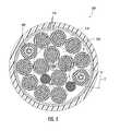
- FIGS. 1 and 3 - 12are radial cross-section views of hybrid cables according to exemplary embodiments.
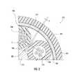
- FIG. 2is a radial cross-section view of a portion of a hybrid cable according to an exemplary embodiment.
- RRHRemote Radio Head
- RFradio frequency
- RRHRemote Radio Head
- Such arrangementmay vary widely, but one suitable arrangement includes use of a cable that combines electrical conductors with fiber optic cables under a single cable jacket, known as a hybrid cable.
- Hybrid cablesinclude fiber optic subunits stranded (for enhanced optical performance and overall cable flexibility) with relatively-high capacity electrical conductors ranging from 10 AWG to 1/0 AWG (i.e., about 5.26-53.5 mm 2 area, about 2.588-8.252 mm diameter, about 3.86-1.21 turns of wire per cm, and about 3.277-0.3224 ⁇ /km for stranded wires, or the equivalent).
- relatively-high capacity electrical conductorsranging from 10 AWG to 1/0 AWG (i.e., about 5.26-53.5 mm 2 area, about 2.588-8.252 mm diameter, about 3.86-1.21 turns of wire per cm, and about 3.277-0.3224 ⁇ /km for stranded wires, or the equivalent).
- Such heavy conductorsmay not be stranded due to the associated forces required to bend and constrain the conductors, and/or because stranding adds length, increasing cable manufacturing expenses due to material costs (e.g., copper).
- material costs
- aspects of the present disclosurerelate to the placement and size of the individual stranded elements (e.g., fiber optic tubes and conductors) of the hybrid cables in order to improve the cost, size, and data-transmission performance of the design.
- Stable hybrid cable coresdue to stranding as well as the placement and size of the stranded elements as disclosed herein, also contribute to the long-term improved performance, weather-ability, and stability of the cable due to enhanced mechanical coupling between the stranded elements.
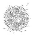
- a hybrid cable 110includes elements 114 stranded around a central guide 112 .
- the elements 114include stranded copper conductors 116 (e.g., 8 AWG) insulated in polyvinyl chloride (PVC) jackets 118 (or another polymeric material, such as fire-retardant (FR) polyethylene (PE)).
- PVCpolyvinyl chloride
- PEpolyethylene
- the diameter of the cablei.e., outer diameter of the radial cross-section, as shown in FIG. 1
- the diameter of the cableis less than 20 mm due to the efficient arrangement of internal cable components, but may also be greater than 10 mm.
- the central guide 112(e.g., central member) of the cable provides a surface for stranding the elements 114 (e.g., winding, helically wrapping), and also includes optical fiber elements 120 in the form of tight-buffered optical fibers (see also FIG. 2 ) within a polymeric tube 122 (e.g., outdoor-rated PVC jacket).
- aramid yarn or other strength membersmay be included within the tube 122 of the guide 112 .
- Filler rods 124are positioned in the interstitial spaces between stranded elements 114
- armor 126surrounds the stranded elements 114 .
- the armor 126may be a corrugated steel, copper, or aluminum armor, which also serves as a ground conductor and/or an electro-magnetic interference (EMI) shield.
- the armormay be dielectric.
- the cable 110includes a polymeric jacket 128 (e.g., PE, FR PE, medium density PE, zero-halogen polymer, outdoor PVC).
- the conductors 116are relatively high-capacity conductors, in the range of 10 AWG to 1 ⁇ 0 AWG (e.g., 8 gauge, 6 gauge), providing a large electrical capacity for powerful electrical equipment (e.g., cell site, radar, FTTA applications), as well as providing axial strength to the cable.
- aspects of the present disclosurerelate to the particular efficient placements and uses of the stranded elements 114 and structure of the cable 110 , as opposed to the general concept of a hybrid cable containing both optical fibers and conductors.
- stranding of the elements 114 of about the same size as one another and in close proximity to one another, as disclosed hereinprovides for improved cable 110 flexibility, as well as improved performance of the optical elements 120 (e.g., less attenuation than un-stranded cables).
- spacing S between stranded elements 214 of a hybrid cable 210is designed to provide a robust cable structure.
- a polygon P(see also FIG. 1 ) may be defined as passing through the centers of adjoining elements 214 stranded about a guide 212 .
- the exteriors of the elements 214are spaced apart from one another at the narrowest distance of the radial cross-section (e.g., shown in FIGS.
- an average distance of separationi.e., spacing S
- the peripheryi.e., gap or spacing between stranded elements is between 2-20%
- ‘average’ distancerefers to the net space of all gaps between adjoining stranded elements divided by the total number of adjoining stranded elements (such as all elements 312 around a core 314 as shown in FIG. 3 ; or all elements on a single layer 612 or 614 , as shown in FIG. 6 ).
- an average gap or spacingmay be between 2-10% of a circumference of a circle intersecting centers of stranded elements, in embodiments where the adjoining stranded elements are of the same diameter.
- the cable 210 of FIG. 2may further include fiber optic elements 216 and electrical-conductor elements 218 in an insulator jacket 220 (e.g., PVC) stranded about the guide 212 , with a water blocking yarn 222 therebetween.
- the fiber optic elements 216are contained in a tube 224 (e.g., the tube mostly consisting of medium density PE).
- the cable 210Exterior to the stranded elements 214 , the cable 210 includes a water-blocking tape 226 , surrounded by armor 228 , in turn surrounded by a polymeric jacket 230 .
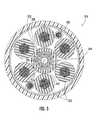
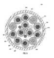
- a hybrid cable 310includes at least six electrical-conductor elements 312 stranded about a guide 314 that includes at least 24 tight-buffered optical fibers 316 in a tube 318 .
- the tight-buffered optical fibers 316are stranded in two discrete layers 320 , 322 about a central glass-reinforced plastic (GRP) rod 324 .
- the electrical-conductor elements 312are insulated and include 6 AWG copper. In other embodiments, the conductors of the cables disclosed herein may be aluminum.
- Two 18 AWG alarm conductors 326are included in the interstitial space to the outside of the stranded electrical-conductor elements 312 , which may carry an alarm signal; such as if connected hardware requires maintenance.
- the 18 AWG conductors 326may carry other signals as well.
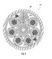
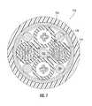
- a hybrid cable 410 of FIG. 4similar to the cable of FIG. 3 , further includes an optical element 430 stranded about the guide 314 .
- the optical element 430is contained in a polymeric jacket 432 (e.g., tube, buffer tube) and that includes at least twelve fibers 434 .
- the stranded optical element 430has fewer fibers 434 and a smaller diameter than the tube 318 integrated with the central guide member 314 (see FIG. 3 ).
- the 6 AWG conductors 312 of either FIG. 3 or FIG. 4share a common diameter D (e.g., within reasonable tolerances; e.g., within 10% of one another).
- the tube 432containing fiber optic elements and stranded about the guide 318 , has a diameter D′ within a range of +10% to ⁇ 20% of the diameter D shared by the 6 AWG conductor elements 312 .
- Sizing the fiber optic tubes 432 to match the conductor 312 diameters Dimproves the robustness of the hybrid cable 410 by reducing the volume of interstitial space within the cable 410 , and correspondingly reducing the volume of space available for migration of the stranded elements 312 , 430 .
- the optical fibers 434 carried by the cable 410generally have less stress when compared cables without such sizing, particularly in bending, due to movement of the elements 312 , 430 .
- a hybrid fiber optic cable 510includes first and second layers 512 , 514 of stranded elements 516 .
- the first layer 512 of stranded elements 516are stranded about a central member 518 (e.g., GRP rod).
- a water-swellable tape 520 and/or a binderSurrounding the first layer 512 , a water-swellable tape 520 and/or a binder at least partially fills the interstitial space.
- the second layer 514includes additional stranded elements 516 .
- the second layer 514includes at least six more stranded elements 516 than the first layer 512 .
- a third layercorrespondingly includes six more elements than the second layer, and so forth.
- tubes 522 containing the fiber optic elementsare positioned in the exterior-most layer, providing ease of access thereto when opening the cable 510 .
- the lay length of the stranded elements 516 of cable 510is between 350-450 mm, providing a good empirically-derived balance between element length, cable flexibility, and low-attenuation of optical fibers.
- the second layer 514is stranded in an opposite direction to the first layer 512 (or mostly so for S-Z stranding of either or both layers), which avoids interstitial conversion of the layers 512 , 514 that may increase attenuation due to extra bending of optical fibers.
- the optical fibers of FIG. 5may be multi-mode fibers, but single-mode fibers may also or alternatively be included.
- the optical fibersmay be loosely placed in buffer tubes, instead of the tight-buffer arrangements as shown; or even ribbons of optical fibers may be included in some contemplated embodiments.
- a hybrid cable 610includes first and second layers 612 , 614 of stranded elements 616 , where some of the elements 616 are electrical-conductor elements 618 and others of the elements are fiber optic elements 620 .
- the cable 610is greater than 30 mm in diameter, but less than 40 mm in diameter due to the compact configuration of stranded elements 616 ; and includes ten 6 AWG conductors 618 , as well as three 12-fiber fiber optic subunits 620 .
- Two 18 AWG conductors 622 and a filler rod 624are positioned within the interstitial spaces surrounding the first layer 612 as well, below a water-blocking tape 626 .
- Water-blocking tape 628also surrounds the second layer 614 , beneath copper armor 630 , which serves as a particularly strong EMI shield below a polymeric jacket 632 .
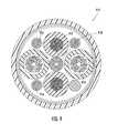
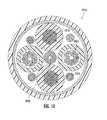
- FIG. 7includes a hybrid cable 710 having equal numbers of fiber optic and main electrical elements 712 , 714 stranded about a central guide 716 .
- Smaller water-blocking yarns 718 and larger filler rods 720 of GRPfill interstitial spaces between the stranded elements 712 , 714 .
- FIGS. 8-10show various alternate embodiments of such hybrid cables 810 , 910 , 1010 , with 2 AWG, 4 AWG, 6 AWG main-electrical conductors 812 , 1012 , 912 , and 12-fiber fiber optic elements 814 , 914 , 1014 .
- the hybrid cables 810 , 910 , 1010also include 18 AWG alarm wires 816 , 916 , 1016 and a GRP central guide up-jacket with a polymer 818 , 918 , 1018 , such as PE.
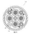
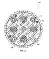
- FIG. 11-12include hybrid cables 1110 , 1210 where the main electrical-conductor elements 1112 , 1212 are substantially larger than the fiber optic elements 1114 , 1214 .
- the electrical-conductor elements 1112 of FIG. 11are 2 AWG, and those 1212 of FIG. 12 are 1/0 AWG.
- the 12-fiber fiber optic elements 1114 , 1214are positioned in the interstitial spaces to the exterior of the main electrical-conductor elements 1112 , 1212 , for ease of access and for providing a compact, robust hybrid cable configuration.
- 11-12also include 18 AWG alarm wires 1116 , 1216 , an up jacketed GRP central guide 1118 , 1218 , and a polyethylene filler rod 1120 , 1220 , which fills the interstitial space between two of the main electrical-conductor elements 1112 , 1212 that is not occupied by a fiber-optic tube 1114 , 1214 including optical fibers.
- cables disclosed hereininclude a number of electrical conductors (e.g., ten or six 6-guage thermoplastic high heat-resistant nylon-coated (THHN) conductors) having a diameter D (see, e.g., FIG. 5 ) that is approximately equal to that diameter D′ of a number of fiber optic tubes also included in the cable (e.g., less than 7 mm diameter D; about 6.3 mm diameter D).
- electrical conductorse.g., ten or six 6-guage thermoplastic high heat-resistant nylon-coated (THHN) conductors
- THNthermoplastic high heat-resistant nylon-coated
- the difference in diameters D, D′ of the stranded elementsis less than 50% of the diameter of the larger of the diameters D, D′ (e.g., less than 25%, less than 10%), or less than twice the diameter of the smaller of the diameters D, D′ (e.g., less than 1.5 times; less than 1.25 times).
- the fiber optic tubescontain multiple optical fibers, such as 36 or 24 fibers net. Applicants have found that standard THHN 6-guage copper conductors have diameters nearly matching those of standard-size buffer tubes of 12-fiber MIC® Cables manufactured by Corning Cable Systems), which may serve as fiber optic subunits. In other embodiments, machine tool wire (MTW) (more insulated than THHN) conductors may be used.
- MMWmachine tool wire
- single-mode optical fibers of the cables shown in FIGS. 1-12 or variations thereofhave an attenuation of 0.4 DB/km or less for 1310 nm wavelength and of 0.3 DB/km or less for 1550 nm wavelength in the stranded configuration of the respective cables.
- Such attenuationis believed to be a significant improvement over hybrid cables that are un-stranded, particularly when the cables are in 90-degree bending.
- the hybrid cablesmay include multi-mode fibers.
- the stranded elementsare helically stranded, while in other embodiments the elements are S-Z stranded.
- the larger diameter elementse.g., 2 AWG or 1/0 AWG THHN or MTW
- larger cablese.g., at least 30 mm in diameter
- Other cables disclosed hereinmay be S-Z stranded, especially those of smaller diameters (e.g., less than 30 mm in diameter) and associated components.
- the stranded elementsi.e., both fiber optic tubes and insulated conductors
- the stranded elementsare stranded in groups of about seven mod six (e.g., 7, 13, 19, 25, . . . with one of the elements in the center), which allows for an even distribution of the elements about the central member with reduced shifting or asymmetry to the position of the elements in the cable.
- multiple layers of stranded elementsare included in the cable, where the outer layers are stranded about the inner layer(s), and where the innermost layer may be stranded about a central member (e.g., spacer, guide).
- the fiber optic tube and optical componentsextend through the central guide member, and the conductors are stranded about the central guide member.
- the fiber optic tubemay be sized, such as via polyethylene up-jacketing, to provide improved spacing between the conductors that are stranded about the central member.
- the stranded conductorsprovide a strength component to the cable, so that the central member need not be a strength member.
- the center of the cableis interstitial space between stranded elements, lacking a solid body; or a guide includes more than one body wound together.
- the electrical conductorsare generally the most numerous and consistently sized elements so, when designing a cable, Applicants generally match the fiber optic units to these, within the range of +10% to ⁇ 20% in outside diameter. If Applicants are still unable to meet the range of +10% to ⁇ 20% in outside diameter, Applicants choose an electrical conductor of the same gauge, but with different insulation thicknesses (e.g. THHN vs. MTW).
- Utilizing the described hybrid cable design features and design rulesoffers a number of advantages, including: (1) stable cable cores that allow for enhanced mechanical coupling between the cable elements, which should offer an improvement in long term cable stability in its installation environment; (2) the above-described features and techniques generally allow for a minimum-size cable cross-section, while containing the requisite stranded elements, where smaller cables are less expensive to make—particularly when considering the cost of an overall armor/shield; and (3) data transmission via optical performance will be improved relative to cables that do not include stranded elements, particularly around bends in the cable due at least in part to reduced tension of the optical fibers.
Landscapes
- Physics & Mathematics (AREA)
- General Physics & Mathematics (AREA)
- Optics & Photonics (AREA)
- Communication Cables (AREA)
Abstract
Description
Claims (20)
Priority Applications (1)
| Application Number | Priority Date | Filing Date | Title |
|---|---|---|---|
| US13/787,062US8909012B2 (en) | 2012-04-27 | 2013-03-06 | Hybrid cable including fiber-optic and electrical-conductor stranded elements |
Applications Claiming Priority (2)
| Application Number | Priority Date | Filing Date | Title |
|---|---|---|---|
| US201261639528P | 2012-04-27 | 2012-04-27 | |
| US13/787,062US8909012B2 (en) | 2012-04-27 | 2013-03-06 | Hybrid cable including fiber-optic and electrical-conductor stranded elements |
Publications (2)
| Publication Number | Publication Date |
|---|---|
| US20130287348A1 US20130287348A1 (en) | 2013-10-31 |
| US8909012B2true US8909012B2 (en) | 2014-12-09 |
Family
ID=49477355
Family Applications (1)
| Application Number | Title | Priority Date | Filing Date |
|---|---|---|---|
| US13/787,062Active2033-05-08US8909012B2 (en) | 2012-04-27 | 2013-03-06 | Hybrid cable including fiber-optic and electrical-conductor stranded elements |
Country Status (1)
| Country | Link |
|---|---|
| US (1) | US8909012B2 (en) |
Cited By (8)
| Publication number | Priority date | Publication date | Assignee | Title |
|---|---|---|---|---|
| US20140226940A1 (en)* | 2013-02-12 | 2014-08-14 | Nexans | Fiber optic cable with improved flexibility, low temperature and compression resistance |
| US20140321822A1 (en)* | 2013-04-25 | 2014-10-30 | Hitachi Metals, Ltd. | Optoelectrical composite cable |
| US20150077740A1 (en)* | 2011-11-01 | 2015-03-19 | Empire Technology Development Llc | Cable with optical fiber for prestressed concrete |
| CN107250865A (en)* | 2015-01-15 | 2017-10-13 | 康宁光电通信有限责任公司 | Hybrid fiber band and power cable |
| US20170316852A1 (en)* | 2014-10-31 | 2017-11-02 | Prysmian S.P.A. | Self-supporting overhead telecommunication/power cable |
| US20180067276A1 (en)* | 2016-09-06 | 2018-03-08 | Commscope Technologies Llc | Hybrid cable transition assembly |
| WO2018053616A1 (en)* | 2016-09-22 | 2018-03-29 | Furukawa Industrial S.A. Produtos Elétricos | Messenger wire for power distribution lines and process for forming a messenger wire for power distribution lines |
| US12032217B2 (en)* | 2019-08-07 | 2024-07-09 | Sterlite Technologies Limited | Cable with interstitial fillers and edge ribbons |
Families Citing this family (15)
| Publication number | Priority date | Publication date | Assignee | Title |
|---|---|---|---|---|
| US9188756B2 (en) | 2012-08-06 | 2015-11-17 | Corning Cable Systems Llc | Hybrid cable with fiber-optic and conductor elements |
| US8886000B2 (en) | 2012-09-05 | 2014-11-11 | Corning Cable Systems Llc | Hybrid fiber-optic cable |
| US20140069682A1 (en)* | 2012-09-11 | 2014-03-13 | Apple Inc. | Cable structures and systems and methods for making the same |
| MX356167B (en)* | 2013-04-24 | 2018-05-17 | Wireco Worldgroup Inc | High-power low-resistance electromechanical cable. |
| NO340781B1 (en)* | 2013-11-18 | 2017-06-19 | Nexans | Downhole pump cable |
| CN103646714A (en)* | 2013-11-29 | 2014-03-19 | 四川鑫电电缆有限公司 | A medium-voltage fiber composite cable |
| US9645341B2 (en) | 2014-02-11 | 2017-05-09 | Commscope Technologies Llc | Cable assembly with connector having twist ability for aligning mating features |
| CN104269220A (en)* | 2014-10-22 | 2015-01-07 | 左常亮 | Waterproof multifunctional cable |
| EP3251178A4 (en) | 2015-01-26 | 2018-08-29 | Commscope Technologies LLC | Hybrid connection system using factory connectorized pigtail |
| CN104715809A (en)* | 2015-02-27 | 2015-06-17 | 安徽卓越电缆有限公司 | Shielded and armored control cable for mining |
| WO2016171970A1 (en)* | 2015-04-23 | 2016-10-27 | Corning Optical Communications LLC | Filler tubes for optical communication cable construction |
| WO2016196016A1 (en)* | 2015-05-29 | 2016-12-08 | Corning Optical Communications LLC | Optical cable with electromagnetic field shield layer |
| US10845558B2 (en)* | 2017-02-07 | 2020-11-24 | Ofs Fitel, Llc | High count optical fiber cable configuration |
| WO2021050324A1 (en) | 2019-09-13 | 2021-03-18 | Commscope Technologies Llc | Hybrid cable for distributed power connectivity |
| CN112562910B (en)* | 2020-12-24 | 2022-10-21 | 江苏亨通光电股份有限公司 | Photoelectric rapid connection optical cable for 5G outdoor micro base station and use method thereof |
Citations (19)
| Publication number | Priority date | Publication date | Assignee | Title |
|---|---|---|---|---|
| US4407561A (en)* | 1980-10-14 | 1983-10-04 | Hughes Aircraft Company | Metallic clad fiber optical waveguide |
| US5325457A (en) | 1991-09-20 | 1994-06-28 | Bottoms Jack Jr | Field protected self-supporting fiber optic cable |
| US5651081A (en) | 1994-06-10 | 1997-07-22 | Commscope, Inc. | Composite fiber optic and electrical cable and associated fabrication method |
| US5917977A (en) | 1997-09-16 | 1999-06-29 | Siecor Corporation | Composite cable |
| US6195487B1 (en) | 1998-06-30 | 2001-02-27 | Pirelli Cable Corporation | Composite cable for access networks |
| US6236789B1 (en) | 1999-12-22 | 2001-05-22 | Pirelli Cables And Systems Llc | Composite cable for access networks |
| US20020001441A1 (en) | 1999-04-13 | 2002-01-03 | Francisco J. Avellanet | Hybrid cable having both an optical fiber and a multifilament twisted and drawn element |
| US6738547B2 (en) | 1998-12-23 | 2004-05-18 | Corning Cable Systems Llc | Composite cable units |
| US7310430B1 (en)* | 2006-06-02 | 2007-12-18 | Sbc Knowledge Ventures | Hybrid cables for communication networks |
| US7643713B2 (en) | 2005-08-31 | 2010-01-05 | Nexans | Composite cable |
| CN102222546A (en) | 2011-06-24 | 2011-10-19 | 航天电工技术有限公司 | Interlocking type armored optical fiber composite low-voltage cable of creep-resistant aluminum alloy conductor |
| CN202067602U (en) | 2010-12-09 | 2011-12-07 | 沈阳亨通光通信有限公司 | Repeater type photoelectric composite cable for metal armouring wire |
| CN202093884U (en) | 2011-06-08 | 2011-12-28 | 昆山信昌电线电缆有限公司 | Photoelectric hybrid cable of high water resistance |
| US20120008904A1 (en) | 2010-07-06 | 2012-01-12 | Hon Hai Precision Industry Co., Ltd. | Optical-electrical hybrid transmission cable |
| CN202134260U (en) | 2011-07-27 | 2012-02-01 | 江苏南瑞淮胜电缆有限公司 | Optical fiber composite insulated power cable |
| US8285095B2 (en) | 2010-07-06 | 2012-10-09 | Hon Hai Precision Ind. Co., Ltd. | Optical-electrical hybrid transmission cable |
| US20120281953A1 (en) | 2011-05-03 | 2012-11-08 | Sehf-Korea Co., Ltd. | Optical electrical hybrid cable |
| US20140064680A1 (en) | 2012-09-05 | 2014-03-06 | James Arthur Register, III | Hybrid fiber-optic cable |
| US20140064681A1 (en) | 2012-08-06 | 2014-03-06 | James Arthur Register, III | Hybrid cable with fiber-optic and conductor elements |
- 2013
- 2013-03-06USUS13/787,062patent/US8909012B2/enactiveActive
Patent Citations (20)
| Publication number | Priority date | Publication date | Assignee | Title |
|---|---|---|---|---|
| US4407561A (en)* | 1980-10-14 | 1983-10-04 | Hughes Aircraft Company | Metallic clad fiber optical waveguide |
| US5325457A (en) | 1991-09-20 | 1994-06-28 | Bottoms Jack Jr | Field protected self-supporting fiber optic cable |
| US5651081A (en) | 1994-06-10 | 1997-07-22 | Commscope, Inc. | Composite fiber optic and electrical cable and associated fabrication method |
| US5917977A (en) | 1997-09-16 | 1999-06-29 | Siecor Corporation | Composite cable |
| US6195487B1 (en) | 1998-06-30 | 2001-02-27 | Pirelli Cable Corporation | Composite cable for access networks |
| US6738547B2 (en) | 1998-12-23 | 2004-05-18 | Corning Cable Systems Llc | Composite cable units |
| US20020001441A1 (en) | 1999-04-13 | 2002-01-03 | Francisco J. Avellanet | Hybrid cable having both an optical fiber and a multifilament twisted and drawn element |
| US6236789B1 (en) | 1999-12-22 | 2001-05-22 | Pirelli Cables And Systems Llc | Composite cable for access networks |
| US7643713B2 (en) | 2005-08-31 | 2010-01-05 | Nexans | Composite cable |
| US20080037941A1 (en) | 2006-06-02 | 2008-02-14 | Mallya Arvind R | Hybrid cables for communication networks |
| US7310430B1 (en)* | 2006-06-02 | 2007-12-18 | Sbc Knowledge Ventures | Hybrid cables for communication networks |
| US20120008904A1 (en) | 2010-07-06 | 2012-01-12 | Hon Hai Precision Industry Co., Ltd. | Optical-electrical hybrid transmission cable |
| US8285095B2 (en) | 2010-07-06 | 2012-10-09 | Hon Hai Precision Ind. Co., Ltd. | Optical-electrical hybrid transmission cable |
| CN202067602U (en) | 2010-12-09 | 2011-12-07 | 沈阳亨通光通信有限公司 | Repeater type photoelectric composite cable for metal armouring wire |
| US20120281953A1 (en) | 2011-05-03 | 2012-11-08 | Sehf-Korea Co., Ltd. | Optical electrical hybrid cable |
| CN202093884U (en) | 2011-06-08 | 2011-12-28 | 昆山信昌电线电缆有限公司 | Photoelectric hybrid cable of high water resistance |
| CN102222546A (en) | 2011-06-24 | 2011-10-19 | 航天电工技术有限公司 | Interlocking type armored optical fiber composite low-voltage cable of creep-resistant aluminum alloy conductor |
| CN202134260U (en) | 2011-07-27 | 2012-02-01 | 江苏南瑞淮胜电缆有限公司 | Optical fiber composite insulated power cable |
| US20140064681A1 (en) | 2012-08-06 | 2014-03-06 | James Arthur Register, III | Hybrid cable with fiber-optic and conductor elements |
| US20140064680A1 (en) | 2012-09-05 | 2014-03-06 | James Arthur Register, III | Hybrid fiber-optic cable |
Non-Patent Citations (7)
| Title |
|---|
| D.L. Collado, B.G. Risch, D.J. Yamasaki, J.D. Gustitus, & J.R. Sach, "Technical Considerations for Composite Cables in Fiber-To-The-Antenna (FTTA) Applications," Copyright 2013, Proceedings of the 62nd International Wire & Cable Symposium Conference, pp. 670-678; Retrieved on Jun. 20, 2014; Available at http://iwcs.omnibooksonline.com/data/papers/2013/14-1.pdf. |
| Draka & Prysmian, "4G Hybrid Cable: Solution for FTTA Wireless Applications," Copyright 2014, pp. 1-2; Retrieved on Jun. 20, 2014; Available at http://na.prysmiangroup.com/en/business-markets/markets/telecom-solutions/resources/datasheets/500D-DS303-4G-FTTA-WIRELESS-0514.pdf. |
| Draka & Prysmian, "4G Hybrid Cable: Solution for FTTA Wireless Applications," Copyright 2014, pp. 1-2; Retrieved on Jun. 20, 2014; Available at http://na.prysmiangroup.com/en/business—markets/markets/telecom-solutions/resources/datasheets/500D—DS303—4G—FTTA—WIRELESS—0514.pdf. |
| Draka, "ezMOBILITY(TM) Solutions," Copyright 2011, pp. 1-4; Retrieved on Jun. 20, 2014; Available at http://www.truenorthtech.com/pdf/ezMOBILITY%20Brochure.pdf. |
| Draka, "ezMOBILITY™ Solutions," Copyright 2011, pp. 1-4; Retrieved on Jun. 20, 2014; Available at http://www.truenorthtech.com/pdf/ezMOBILITY%20Brochure.pdf. |
| Nexans, "Outdoor hybrid cables (unshielded)," Retrieved on Jun. 23, 2014 from http://www.nexans.fr/eservice/France-en/pdf-family-9444/Outdoor-hybrid -cables-unshielded -.pdf-3 pages. |
| Nexans, "Outdoor hybrid cables (unshielded)," Retrieved on Jun. 23, 2014 from http://www.nexans.fr/eservice/France-en/pdf-family—9444/Outdoor—hybrid —cables—unshielded —.pdf—3 pages. |
Cited By (14)
| Publication number | Priority date | Publication date | Assignee | Title |
|---|---|---|---|---|
| US20150077740A1 (en)* | 2011-11-01 | 2015-03-19 | Empire Technology Development Llc | Cable with optical fiber for prestressed concrete |
| US9575271B2 (en)* | 2011-11-01 | 2017-02-21 | Empire Technology Development Llc | Cable with optical fiber for prestressed concrete |
| US9086556B2 (en)* | 2013-02-12 | 2015-07-21 | Nexans | Fiber optic cable with improved flexibility, low temperature and compression resistance |
| US20140226940A1 (en)* | 2013-02-12 | 2014-08-14 | Nexans | Fiber optic cable with improved flexibility, low temperature and compression resistance |
| US20140321822A1 (en)* | 2013-04-25 | 2014-10-30 | Hitachi Metals, Ltd. | Optoelectrical composite cable |
| US9417416B2 (en)* | 2013-04-25 | 2016-08-16 | Hitachi Metals, Ltd. | Optoelectrical composite cable |
| US10475556B2 (en)* | 2014-10-31 | 2019-11-12 | Prysmian S.P.A. | Self-supporting overhead telecommunication/power cable |
| US20170316852A1 (en)* | 2014-10-31 | 2017-11-02 | Prysmian S.P.A. | Self-supporting overhead telecommunication/power cable |
| AU2014410394B2 (en)* | 2014-10-31 | 2020-11-05 | Prysmian S.P.A. | Self-supporting overhead telecommunication/power cable |
| CN107250865A (en)* | 2015-01-15 | 2017-10-13 | 康宁光电通信有限责任公司 | Hybrid fiber band and power cable |
| US10191239B2 (en)* | 2016-09-06 | 2019-01-29 | Commscope Technologies Llc | Hybrid cable transition assembly |
| US20180067276A1 (en)* | 2016-09-06 | 2018-03-08 | Commscope Technologies Llc | Hybrid cable transition assembly |
| WO2018053616A1 (en)* | 2016-09-22 | 2018-03-29 | Furukawa Industrial S.A. Produtos Elétricos | Messenger wire for power distribution lines and process for forming a messenger wire for power distribution lines |
| US12032217B2 (en)* | 2019-08-07 | 2024-07-09 | Sterlite Technologies Limited | Cable with interstitial fillers and edge ribbons |
Also Published As
| Publication number | Publication date |
|---|---|
| US20130287348A1 (en) | 2013-10-31 |
Similar Documents
| Publication | Publication Date | Title |
|---|---|---|
| US8909012B2 (en) | Hybrid cable including fiber-optic and electrical-conductor stranded elements | |
| US9188756B2 (en) | Hybrid cable with fiber-optic and conductor elements | |
| US8886000B2 (en) | Hybrid fiber-optic cable | |
| AU2013248177B2 (en) | An optical fiber cable | |
| US6343172B1 (en) | Composite fiber optic/coaxial electrical cables | |
| US5917977A (en) | Composite cable | |
| US6519399B2 (en) | Fiber optic cable with profiled group of optical fibers | |
| US9788469B2 (en) | Optical cable with electromagnetic field shield layer | |
| US10345544B1 (en) | Composite optoelectronic HDMI cable | |
| US6463198B1 (en) | Micro composite fiber optic/electrical cables | |
| US20190295745A1 (en) | Hdmi photoelectric composite cable and method for manufacturing the same | |
| US9482836B2 (en) | Composite electro/optical microcable | |
| EP0946951A1 (en) | Multiple twisted pair data cable with geometrically concentric cable groups | |
| US11714248B2 (en) | High density bundled optical fiber cable with preconnectorized drop points | |
| US11187866B2 (en) | Fiber multitube optical fiber cable | |
| US20190113703A1 (en) | Fiber Optic Drop Cable | |
| US11942235B2 (en) | Hybrid cable for distributed power connectivity | |
| AU2014410394B2 (en) | Self-supporting overhead telecommunication/power cable | |
| EP2482110B1 (en) | Optical assembly and optical cable thereof | |
| US12298575B2 (en) | Aerial drop optical fiber cable | |
| US20230251444A1 (en) | Aerial drop optical fibre cable |
Legal Events
| Date | Code | Title | Description |
|---|---|---|---|
| AS | Assignment | Owner name:CORNING CABLE SYSTEMS LLC, NORTH CAROLINA Free format text:ASSIGNMENT OF ASSIGNORS INTEREST;ASSIGNORS:REGISTER, JAMES ARTHUR, III;SMITH, DAVID HENRY;REEL/FRAME:030666/0549 Effective date:20130612 | |
| STCF | Information on status: patent grant | Free format text:PATENTED CASE | |
| AS | Assignment | Owner name:CORNING OPTICAL COMMUNICATIONS LLC, NORTH CAROLINA Free format text:CHANGE OF NAME;ASSIGNOR:CORNING CABLE SYSTEMS LLC;REEL/FRAME:040126/0818 Effective date:20140114 | |
| AS | Assignment | Owner name:CCS TECHNOLOGY, INC., DELAWARE Free format text:ASSIGNMENT OF ASSIGNORS INTEREST;ASSIGNOR:CORNING OPTICAL COMMUNICATIONS LLC;REEL/FRAME:040663/0047 Effective date:20160419 | |
| AS | Assignment | Owner name:CORNING OPTICAL COMMUNICATIONS LLC, NORTH CAROLINA Free format text:MERGER;ASSIGNORS:CCS TECHNOLOGY, INC.;CORNING OPTICAL COMMUNICATIONS BRANDS, INC.;REEL/FRAME:043601/0427 Effective date:20170630 | |
| MAFP | Maintenance fee payment | Free format text:PAYMENT OF MAINTENANCE FEE, 4TH YEAR, LARGE ENTITY (ORIGINAL EVENT CODE: M1551) Year of fee payment:4 | |
| MAFP | Maintenance fee payment | Free format text:PAYMENT OF MAINTENANCE FEE, 8TH YEAR, LARGE ENTITY (ORIGINAL EVENT CODE: M1552); ENTITY STATUS OF PATENT OWNER: LARGE ENTITY Year of fee payment:8 |