US8908389B2 - Power distribution system and helmet and method employing the same - Google Patents
Power distribution system and helmet and method employing the sameDownload PDFInfo
- Publication number
- US8908389B2 US8908389B2US13/647,515US201213647515AUS8908389B2US 8908389 B2US8908389 B2US 8908389B2US 201213647515 AUS201213647515 AUS 201213647515AUS 8908389 B2US8908389 B2US 8908389B2
- Authority
- US
- United States
- Prior art keywords
- helmet
- circuit
- electrical
- distribution system
- power distribution
- Prior art date
- Legal status (The legal status is an assumption and is not a legal conclusion. Google has not performed a legal analysis and makes no representation as to the accuracy of the status listed.)
- Active, expires
Links
- 238000000034methodMethods0.000titleclaimsabstractdescription9
- 238000009826distributionMethods0.000titleclaimsdescription21
- 239000000758substrateSubstances0.000claimsabstractdescription40
- 239000000463materialSubstances0.000claimsdescription11
- 238000004891communicationMethods0.000claimsdescription10
- 238000010276constructionMethods0.000claimsdescription10
- 230000008878couplingEffects0.000claimsdescription5
- 238000010168coupling processMethods0.000claimsdescription5
- 238000005859coupling reactionMethods0.000claimsdescription5
- 230000003287optical effectEffects0.000claimsdescription5
- 239000004020conductorSubstances0.000claimsdescription4
- 230000005236sound signalEffects0.000claims2
- 238000013500data storageMethods0.000claims1
- 239000012777electrically insulating materialSubstances0.000claims1
- 238000003384imaging methodMethods0.000description10
- 230000004297night visionEffects0.000description6
- 230000005540biological transmissionEffects0.000description4
- 239000004033plasticSubstances0.000description4
- 238000003860storageMethods0.000description3
- 230000004075alterationEffects0.000description2
- 238000006243chemical reactionMethods0.000description2
- 238000000151depositionMethods0.000description2
- 238000005530etchingMethods0.000description2
- 239000003733fiber-reinforced compositeSubstances0.000description2
- 210000003128headAnatomy0.000description2
- 230000013011matingEffects0.000description2
- 230000007246mechanismEffects0.000description2
- 239000002184metalSubstances0.000description2
- 238000012986modificationMethods0.000description2
- 230000004048modificationEffects0.000description2
- 230000037361pathwayEffects0.000description2
- 230000008054signal transmissionEffects0.000description2
- 238000001931thermographyMethods0.000description2
- OKTJSMMVPCPJKN-UHFFFAOYSA-NCarbonChemical compound[C]OKTJSMMVPCPJKN-UHFFFAOYSA-N0.000description1
- 229920000271Kevlar®Polymers0.000description1
- 239000004642PolyimideSubstances0.000description1
- 239000004760aramidSubstances0.000description1
- 229920006231aramid fiberPolymers0.000description1
- 238000000429assemblyMethods0.000description1
- 230000000712assemblyEffects0.000description1
- 229910052799carbonInorganic materials0.000description1
- 239000003086colorantSubstances0.000description1
- 239000011231conductive fillerSubstances0.000description1
- 230000008021depositionEffects0.000description1
- 238000009713electroplatingMethods0.000description1
- 239000008393encapsulating agentSubstances0.000description1
- 230000004438eyesightEffects0.000description1
- 239000000835fiberSubstances0.000description1
- 238000002347injectionMethods0.000description1
- 239000007924injectionSubstances0.000description1
- 238000001746injection mouldingMethods0.000description1
- 230000010354integrationEffects0.000description1
- 238000004519manufacturing processMethods0.000description1
- 238000003032molecular dockingMethods0.000description1
- 238000000465mouldingMethods0.000description1
- 229920000728polyesterPolymers0.000description1
- 229920001721polyimidePolymers0.000description1
- 239000002952polymeric resinSubstances0.000description1
- 238000007639printingMethods0.000description1
- 230000001681protective effectEffects0.000description1
- 229920003002synthetic resinPolymers0.000description1
Images


Classifications
- A—HUMAN NECESSITIES
- A42—HEADWEAR
- A42B—HATS; HEAD COVERINGS
- A42B3/00—Helmets; Helmet covers ; Other protective head coverings
- A42B3/04—Parts, details or accessories of helmets
- F—MECHANICAL ENGINEERING; LIGHTING; HEATING; WEAPONS; BLASTING
- F41—WEAPONS
- F41H—ARMOUR; ARMOURED TURRETS; ARMOURED OR ARMED VEHICLES; MEANS OF ATTACK OR DEFENCE, e.g. CAMOUFLAGE, IN GENERAL
- F41H1/00—Personal protection gear
- F41H1/04—Protection helmets
- H—ELECTRICITY
- H02—GENERATION; CONVERSION OR DISTRIBUTION OF ELECTRIC POWER
- H02J—CIRCUIT ARRANGEMENTS OR SYSTEMS FOR SUPPLYING OR DISTRIBUTING ELECTRIC POWER; SYSTEMS FOR STORING ELECTRIC ENERGY
- H02J1/00—Circuit arrangements for DC mains or DC distribution networks
Definitions
- the present disclosurerelates generally to protective helmets such as a ballistic helmet or other helmets having a similar construction, such as a ballistic tactical helmet for use by law enforcement personnel, military field or combat helmets, or the like. More particularly, the present disclosure relates to an electrical power distribution system for a helmet, and a method and helmet employing the same, the power distribution system employing a circuit carried on a flexible circuit substrate to generally conform to the shape of the helmet, the flexible circuit substrate carrying thereon a conductive layer comprising conductive tracings, etchings, depositions, or the like, applied in a preselected pattern configured to provide the desired electrical connections between one or more electronic accessory devices or components attached or mounted to the helmet.
- a military ballistic helmet or the likeis configured to carry one or more accessories or attachments, such as a flashlight, viewing optics and devices, such as a monocular, binoculars, monocular or binocular night vision goggle (NVG) devices (NVG, including enhanced night vision goggle devices (ENVG)), thermal imaging devices, cameras, friend or foe identification (IFF) systems, and so forth.
- a flashlightviewing optics and devices, such as a monocular, binoculars, monocular or binocular night vision goggle (NVG, including enhanced night vision goggle devices (ENVG)), thermal imaging devices, cameras, friend or foe identification (IFF) systems, and so forth.
- NVGmonocular, binoculars, monocular or binocular night vision goggle devices
- ENVGenhanced night vision goggle devices
- IFFfriend or foe identification
- the helmetmay be provided with a plurality of openings or holes therein for mounting such accessories to the helmet or for receiving fasteners or other mounting mechanisms or hardware such as threaded fasteners, brackets, grommets, etc.
- the front of a helmetmay have openings and holes for mounting an accessory such as a flashlight or a bracket or shroud which can accept a helmet mount for a viewing device as described above.
- holes or vias through the ballistic materialmay be provided in order to provide an electrical connection between a power supply mounted at one location on the helmet, e.g., at the rear of the helmet, and an accessory or device located at another position on the helmet, e.g., by running an electrical cable along the interior of the helmet.
- helmet mounted componentsSuch hardware or openings which penetrate the ballistic shell, either partially or completely, compromise the anti-ballistic properties of the helmet in these regions.
- the number and complexity of helmet mounted componentsare increasing, and such components may be computer or microcontroller-based and controlled through the use of electronic signals and sensors, thus resulting in larger and more complex wiring assemblies and posing difficulties in installing such devices while maintaining the ballistic integrity of the helmet.
- the inventionmay take form in various components and arrangements of components, and in various steps and arrangements of steps.
- the drawingsare only for purposes of illustrating preferred embodiments and are not to be construed as limiting the invention.
- FIG. 1is a front elevational view of an exemplary helmet in accordance with the present disclosure.
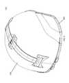
- FIG. 2is a rear elevational view of the embodiment appearing in FIG. 1 .
- FIG. 3is a side elevational view of the embodiment appearing in FIG. 1 .
- FIG. 4is a top plan view of the embodiment appearing in FIG. 1 .
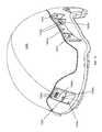
- FIG. 5is an isometric view of the embodiment appearing in FIG. 1 , taken generally from the rear and side.
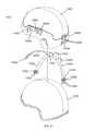
- FIG. 6is a partially exploded isometric view of the embodiment appearing in FIG. 1 illustrating the laminated construction of the ballistic preform or layup, the flexible circuit substrate, and the outer shell or skin.
- FIG. 7is an exploded view of the ballistic layup component and the circuit assembly.
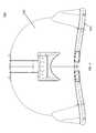
- FIG. 8is an enlarged view of the circuit substrate and mounting bezels.
- FIG. 9is an enlarged view of the region “A” appearing in FIG. 8 .
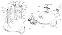
- FIG. 10is an isometric view of the embodiment appearing in FIG. 1 , taken generally from the front and side, and having several exemplary accessory devices mounted on the helmet.
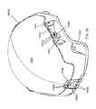
- FIG. 11is an isometric view of the embodiment appearing in FIG. 10 , taken generally from the rear and side.
- FIG. 12is an exploded view showing the attachment mechanisms for the exemplary accessory devices.
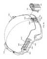
- FIG. 13is an isometric view taken generally from the rear and side showing an adapter for electrically coupling an accessory device located remotely from the user.
- FIG. 14is an exploded view of a helmet with further exemplary embodiment of the power distribution system herein.
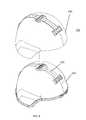
- FIG. 15is front isometric view of the helmet embodiment appearing in FIG. 14 .
- FIG. 16is a rear isometric view of the helmet embodiment appearing in FIG. 14 .
- FIGS. 17 and 18are, respectively, front and rear isometric view of the helmet embodiment appearing in FIG. 14 , with an exemplary power supply and adapters attached thereto.
- a helmet system and methodare provided that allow an electrical connection between two or more electrical or electronic components on the helmet by integrating a flexible circuit substrate and mounting plate assembly into or on top of the construction of a helmet shell.
- the circuit layerdefines a circuit and includes a plurality of terminal pads. Each terminal pad includes two or more electrical contacts.
- the circuitalso includes electrical conductors interconnecting the terminal pads.
- a coveris attached to the circuit layer over each terminal pad, the cover having an aperture aligned with and exposing the electrical contacts.
- One or more mechanical fastenersare configured to removably and securely hold a helmet accessory in mechanical contact with the cover and in electrical contact with the exposed electrical contacts.
- a helmet constructioncomprising the helmet accessory power distribution system herein and a helmet attached to the circuit layer.
- a method of providing a supply of electrical power to one or more electrical power-consuming devices attached to a helmetcomprises the step of providing a circuit layer extending across a portion of the helmet, wherein the circuit layer defines a circuit and includes a plurality of terminal pads. Each of the terminal pads includes two or more electrical contacts. The circuit also includes electrical conductors interconnecting the terminal pads. Covers are attached to the circuit layer over each terminal pad, the covers having an aperture aligned with and exposing the electrical contacts. A power supply is secured to one of the covers and an electrical power-consuming device is secured to another one of the covers using one or more mechanical fasteners.
- the one or more mechanical fastenersare configured to removably and securely hold the power supply and the electrical power-consuming device in mechanical contact with the respective cover and in electrical contact with the exposed electrical contacts. Power is then delivered from the power supply to the electrical power-consuming device through the circuit layer.
- the helmet system and methodallow a secure connection of helmet mounted accessories to the helmet without the need to penetrate any one or more layers of the ballistic shell with mounting hardware, fasteners, wiring vias, and so forth. It is to be understood that both the following detailed description is exemplary and explanatory only and are not restrictive of the invention.
- FIGS. 1-8illustrate a ballistic helmet 100 which includes a ballistic shell or base layer 200 , an intermediate circuit layer 300 , and an outer layer(s) 400 , formed in accordance with an embodiment of the present disclosure.
- the base layer 200may comprise a molded helmet base, e.g., formed by laying up and molding on a generally helmet shaped pre-form multiple plies of a fiber reinforced composite material, such as aramid fibers (e.g., KEVLAR®) or other ballistic fiber impregnated with a polymer resin.
- aramid fiberse.g., KEVLAR®
- Other ballistic and non-ballistic helmet types, including metal helmets,are also contemplated.
- An example of a ballistic helmet into which an integrated accessory mounting and electrical interconnection may be providedincludes ballistic helmets available from Ceradyne under the product name SEAMLESS BALLISTIC® Helmet.
- the present laminated construction in accordance with this disclosuremay be adapted for use with a base component 200 formed of other materials, including other plastic or metal helmet types.
- the base layermay be a finished helmet or, alternatively, may be an unfinished helmet.
- the outer layer 400serves to retain the circuit layer 300 and allows existing helmets to be retrofit with the powered helmet mounting system in accordance with this disclosure.
- the outer shell 400may comprise one or more plies of a ballistic fiber reinforced composite material which contributes to the ballistic integrity of the finished helmet.
- the circuit layer 300includes a circuit substrate 302 formed of a flexible material, such as a flexible film or tape, e.g., polyimide, polyester or other material that is able to withstand the elevated temperatures that may result from the bonding and curing of the helmet 100 components.
- a conductive, e.g., metalized, patternis formed on the substrate 302 and is comprised of one or more conductive pathways to provide power, control, and/or data signals between two or more mounting plates.
- the electrically conductive patternmay be formed via etching, depositing, printing (e.g., using a conductive ink containing carbon or other conductive filler), electro plating, or the like to provide a desired conductive pattern
- the illustrated circuit substrate 302is shown with 3 mounting plates, any number may be provided. In certain embodiments, the number of mounting plates may range from 2 to 6 or more.
- Such conductive pathwaysmay be formed in any desired circuit pattern for providing one or more electrical power transmission paths, one or more data transmission paths, one or more control signal transmission paths, or any combinations thereof, as required.
- circuit componentssuch as one or more antennae may be formed as a part of the electrically conductive pattern on the circuit substrate.
- one or more communications antennaemay be formed on the circuit substrate and electrically coupled to a communications device of the type which aids in wireless communications between devices or the wearer and other operators.
- Such communications devicemay be mounted on the helmet and electrically coupled to the antennae via the exposed terminals on the circuit 300 .
- an antenna pattern on the circuit substrate 302may be electrically coupled via an adaptor (as detailed below) to a remote communications device worn or carried by the user and located remotely from the helmet.
- RFIDradio frequency identification
- GPSGPS antenna(s) for coupling to a navigation system worn by the user and either mounted to the helmet system 100 herein or worn or carried elsewhere on the user and eclectically coupled via an adapter such as that described below.
- the conductive patternmay be coated with an encapsulant and/or laminated to protect the circuit pattern from damage.
- the circuit substrate 302is generally elongate in shape and the long axis extends along the top of the base 200 from front to back and along the centerline 202 of the base 200 , although it will be recognized that other orientations are possible.
- the circuit substrate 302may extend transversely with respect to the median plane of the wearer's body, circumferentially with respect to the wearer's head, etc.
- the circuit substratemay be any other desired geometric shape, including without limitation, generally rectangular, generally circular, or any other desired symmetrical or asymmetrical shape.
- the illustrated circuit substrate 302includes three pairs of transversely aligned mounting tabs 304 a , 304 b , and 304 c , with each tab containing a respective opening 306 a , 306 b , 306 c , therein.
- a first, front contact plate or bezel 308 aincludes a pair of openings 310 a aligned with the pair of openings 306 a .
- an opening 312 ais located between the pair of openings 310 a to expose contact pads 314 a on the circuit substrate 302 defining a first set of terminals on the circuit pattern.
- a second, intermediate contact plate or bezel 308 bincludes a pair of openings 310 b aligned with the pair of openings 306 b .
- An opening 312 bis located between the pair of openings 310 b to expose contact pads 314 b on the circuit substrate 302 defining a second set of terminals on the circuit pattern.
- a third, rear contact plate or bezel 308 cincludes a pair of openings 310 c aligned with the pair of openings 306 c .
- An opening 312 cis located between the pair of openings 310 c to expose contact pads 314 c on the circuit substrate 302 defining a third set of terminals on the circuit pattern.
- Each of the contact plates 308 a , 308 b , 308 cis secured to the circuit substrate 302 using a pair of threaded grommets 316 a , 316 b , 316 c , respectively.
- the grommets 316 a , 316 b , and 316 cpass through the openings 310 a , 310 b , and 310 c and the respective opening 306 a , 306 b , and 306 c in a corresponding one of the tabs 304 a , 304 b , and 304 c .
- Each of the grommets 316 a , 316 b , and 316 cincludes outer helical threads for receiving a nut 318 a , 318 b , and 318 c , respectively, to thereby engage the respective contact plates 308 a , 308 b , and 308 c to the flexible circuit substrate 302 .
- Each of the grommets 316 a , 316 b , and 316 calso includes an internally threaded or tapped opening for the removable attachment of a helmet mounted accessory device.
- the removably attached accessory deviceincludes an electrical connector which is complimentary and matable with the openings 312 a , 312 b , and/or 312 c and which includes an aligned and facing set of contacts or terminals which contact the contact pads 314 b when the accessory device is installed on the respective connector 308 a , 308 b , 308 c .
- the mating connector on the accessory deviceincludes threaded fasteners each of which is removably received in a corresponding aligned one of the internally threaded openings in the grommets 316 a , 316 b , 316 c.
- the circuit layer 300may be advantageously encapsulated in the outer layer or layers 400 that may be a ballistic (i.e., ballistic-resistant) or non-ballistic material.
- the low profile of the assemblyis designed to allow for integration into a variety of manufacturers helmet layups and manufacturing processes.
- the mounting plates 308 a , 308 b , and 308 cmay be integrally formed with the outer layer 400 .
- the mounting plates 308 a , 308 b , 308 c and the outer layer 400are formed, e.g., via injection molding, as a single, monolithic member for subsequent attachment to circuit substrate 302 and to the base member 200 .
- a monolithcomprising mounting plates 308 a , 308 b , 308 c , and the outer layer 400 can be formed by overmolding, e.g., injection overmolding, directly over the base 200 , circuit substrate 302 , and fasteners 316 a , 316 b , 316 c and 318 a , 318 b , 318 c.
- overmoldinge.g., injection overmolding
- FIGS. 10-12Exemplary accessory devices mounted on the powered helmet embodiment of FIGS. 1-9 appear in FIGS. 10-12 .
- a rear mounting plate 500is attached to the rear connector 308 c using fasteners 502 which mate with the pair of threaded grommets 316 c .
- the rear mounting plate 500includes spring-loaded contact pins 504 which mate with contact pads 314 c .
- An accessory device 520may be removably attached to the rear mounting plate 500 .
- the accessory device 520may be a power supply such as a battery or battery pack which supplies electrical power to a device(s) attached to the connectors 308 b and/or 308 a.
- a digital video recordermay be removably connected to the rear mounting plate 500 for storing a digital representation of a video signal received from a remote video camera or imaging device, such as a video camera or imaging device worn by the user, e.g., a video camera or imaging device attached to another one of the connectors 308 a and 308 b .
- the storage mediummay be a hard disk drive, memory card, optical disk, or other electronic storage medium as known in the art.
- the video signalmay be output from the video/imaging device as a digital signal for storage on the recorded device, or alternatively, may be an analog video signal for conversion to a digital representation via analog-to-digital signal processing electronics onboard the accessory device 520 .
- the video signal(analog or digital) may be passed from the video camera/imaging device directly to the recording device via a wired or wireless (e.g., radio frequency) transmission.
- the analog or digital video signalmay be passed from the video camera/imaging device via the conductive pattern formed on the circuit substrate 302 .
- a top mounting plate 600may be attached to the contact plate 308 b using fasteners 602 which mate with the pair of threaded grommets 316 b .
- the top mounting plate 600includes spring loaded contact pins (not shown) which mate with contact pads 314 b .
- An accessory device(not shown) may be removably attached to the top mounting plate 600 .
- the accessory devicemay be a power supply such as a battery or battery pack which supplies electrical power to a device(s) attached to the connectors 308 a and/or 308 c .
- the top mounting plate 600may include an attached identification friend-or-foe (IFF) transponder (not shown), which may be electrically coupled to the battery pack 520 via the circuit pattern of the circuit substrate 302 . It will be recognized that other electrically operated devices, such as communication systems, may be employed in place of the illustrated IFF transponder.
- IFFidentification friend-or-foe
- a front mounting plate 700may be attached to the contact plate 308 a using fasteners 702 which mate with the pair of threaded grommets 316 a .
- the front mounting plate 700includes spring loaded contact pins (not shown) which mate with contact pads 314 a .
- An accessory device(not shown) may be removably attached to the front mounting plate 700 .
- the accessory devicemay be one or more viewing optics and/or imaging devices, such as a monocular, binoculars, monocular or binocular NVG devices, including ENVG devices, thermal imaging devices, cameras, head up display, virtual reality or immersive display, friend or foe identification (IFF) systems, and so forth which may be powered by a power supply attached to the connectors 308 b and/or 308 c.
- the front mounting plate 700is illustrated includes an LED flashlight 704 , a video camera 706 , and a powered circuit board 708 , e.g., in electrical communication with the power source 520 via the contacts 314 b for powering the attached accessory device (not shown).
- the LED flashlight 704may include a rotating bezel 710 for selectively changing the colors of the flashlight 704 and a power button 712 .
- the video camera 706may include buttons, keypad, or the like for controlling the video camera functions, such as a power button 714 for powering on or off a remote video recording device, a record button 716 to toggle between recording and nonrecording modes, and so forth.
- Control signals from the buttons/keys 714 , 716may be passed to a digital video recorder (DVR) module (not shown), mounted on the connector 308 b or 308 c , the signals passing via the conductive circuit substrate 302 or, alternatively, via a dedicated wired or wireless connection or interface between the module 700 and the DVR module.
- DVRdigital video recorder
- an auxiliary camera(which may in addition to or as an alternative to the camera 706 ) may be provided as a removably attached device.
- a viewing device attached to the front mount 700may include a camera, either as an integral component or as an add-on component.
- auxiliary cameramay be a night time or low lux camera.
- a beam splittermay be provided, e.g., carried on an adapter ring adapted to be received over the viewing end of the night vision or other viewing device.
- the beam splittercan be supported along the optical path of the viewing device such that a portion of the output image is reflected 90 degrees with respect to the optical axis to the a camera device for recording.
- the portion of the output image from the viewing device that is not reflected by the beam splitterpasses through the beam splitter to the user's eye.
- the output display of the viewingcan be simultaneously recorded as video data and simultaneously viewed by the user.
- An exemplary camera and recording systemmay be shown and described in the above-incorporated U.S. patent application Ser. No. 11/972,040 filed Jan. 8, 2008 and U.S. Publication No. US2008/0170838.
- the front mounting plate 700 and its integrated power contact 708can be used in conjunction with a mounting apparatus (not shown), e.g., to position a viewing device before the eye(s) of a user donning the system 100 .
- the mounting apparatusis a pivoting helmet mount of the type used to selectively pivot a viewing device between a viewing position in front of the eye(s) of a user and a stowed position up and out of the user's line of sight.
- the viewing devicemay be a night vision goggle (monocular or binocular) device or other optical or imaging device, such as thermal or infrared (IR) devices (including shortwave IR devices), head mounted displays (such as head-up displays, immersive displays, etc.), or other type of device.
- IRinfrared
- head mounted displayssuch as head-up displays, immersive displays, etc.
- the adapter 800includes a first electrical connector 802 which is removably received on the rear mounting plate 500 in place of the battery pack 520 (see FIG. 11 ) to provide an electrical coupling between the circuit substrate 302 and the first adapter 802 .
- the first connector 802is electrically coupled to a second electrical connector 804 via a conductive cable 806 .
- the second connector 804is adapted to mate with an electrical connector on a remote power supply, e.g., contained in a device, article or piece of equipment carried by or worn by the user.
- the adapter 800 and the circuit layer 300cooperate to provide power to an attached accessory device.
- the adapter 800may also be used in conjunction with one or more buttons or keys to provide remotely actuated control signals for controlling operation of an accessory device mounted on the helmet via the circuit layer 300 .
- the front arm 1302 aincludes a circuit substrate carrying conductive circuit components for delivery of electrical power and/or data or signal to a plurality of contact pads 1322 a .
- the distal portion of the circuit substrate arm 1302 amay be housed in a housing 1320 a , such as a plastic housing, with aligned openings to expose the contact pads and provide additional rigidity around the terminal pads.
- the housings 1320 a , 1320 b , 1320 c in the depicted embodiment of FIGS. 14-18may be adhesively bonded to the circuit substrate, attached using mechanical fasteners, and so forth.
- the covering 1400provides an outer layer which may or may not provide further anti-ballistic properties of the helmet.
- the outer layerincludes integrally molded mounting features, including a front mounting member 1402 a , a rear mounting member 1402 b , and two side mounting members 1402 c .
- the molded mounting featurescould be separately formed and applied under the shell layer.
- the front mounting feature 1402 aincludes an opening 1406 a exposing the contact pads 1322 a .
- Additional mounting hardwaremay be embedded between the base layer 1200 and the outer layer 1400 , such as an internally threaded boss 1404 extending through an opening 1408 a in the mounting member 1402 a for attachment of an accessory device or mounting adapter for an accessory.
- Such helmet mountsare generally known in the art, see for example, commonly owned U.S. Pat. No. 7,219,370 issued May 22, 2007; U.S. Published Application Nos. 2011/0145981 published Jun. 23, 2011, 2007/0214551 published Sep. 20, 2007, and 2010/0299814 published Dec. 02, 2010; and U.S. application Ser. Nos. 12/117,704 filed May. 08, 2008, Ser. No. 12/259,010 filed Oct. 27, 2010, Ser. No. 12/759,435 filed Oct. 27, 2010, Ser. No. 13/019,889 filed Feb. 02, 2011, 61/351,084 filed Jun. 03, 2010, 61/300,770 filed Feb. 02, 2010, and 61/263,159 filed Nov. 20, 2009.
- Each of the aforementioned referencesis incorporated hereby be reference in its entirety.
Landscapes
- Engineering & Computer Science (AREA)
- Power Engineering (AREA)
- General Engineering & Computer Science (AREA)
- Helmets And Other Head Coverings (AREA)
Abstract
Description
Claims (20)
Priority Applications (1)
| Application Number | Priority Date | Filing Date | Title |
|---|---|---|---|
| US13/647,515US8908389B2 (en) | 2011-10-07 | 2012-10-09 | Power distribution system and helmet and method employing the same |
Applications Claiming Priority (2)
| Application Number | Priority Date | Filing Date | Title |
|---|---|---|---|
| US201161545076P | 2011-10-07 | 2011-10-07 | |
| US13/647,515US8908389B2 (en) | 2011-10-07 | 2012-10-09 | Power distribution system and helmet and method employing the same |
Publications (2)
| Publication Number | Publication Date |
|---|---|
| US20130086722A1 US20130086722A1 (en) | 2013-04-11 |
| US8908389B2true US8908389B2 (en) | 2014-12-09 |
Family
ID=48041083
Family Applications (1)
| Application Number | Title | Priority Date | Filing Date |
|---|---|---|---|
| US13/647,515Active2033-03-22US8908389B2 (en) | 2011-10-07 | 2012-10-09 | Power distribution system and helmet and method employing the same |
Country Status (1)
| Country | Link |
|---|---|
| US (1) | US8908389B2 (en) |
Cited By (34)
| Publication number | Priority date | Publication date | Assignee | Title |
|---|---|---|---|---|
| US20160029729A1 (en)* | 2014-07-31 | 2016-02-04 | Bell Sports, Inc. | Helmet with integrated electronics and helmet visor controls |
| USD778508S1 (en)* | 2014-11-25 | 2017-02-07 | Ty-Flot, Inc. | Clip for a universal accessory slot of a hard hat |
| US20170071279A1 (en)* | 2015-09-14 | 2017-03-16 | Trent Zimmer | Helmet mounted lighting system |
| US9800083B1 (en)* | 2015-09-04 | 2017-10-24 | Elijah Alexander Supper | Audio signal conveying power supply |
| ITUA20164059A1 (en)* | 2016-06-01 | 2017-12-01 | Ottaviano Salerno | PROTECTIVE HELMET WITH UNIVERSAL HOUSING FOR ELECTRONIC DEVICES |
| US10079488B2 (en) | 2015-02-20 | 2018-09-18 | William M. Challancin | Power supply apparatus |
| US20190011702A1 (en)* | 2017-07-06 | 2019-01-10 | RAVR Incorporation Ltd. | Helmet-Mounted Visualization Device Without Parallax and its Operation Method |
| USD848078S1 (en) | 2018-11-15 | 2019-05-07 | Jared Michael Griffith | Hard hat accessory adapter |
| USD894494S1 (en) | 2006-02-09 | 2020-08-25 | Gentex Corporation | Helmet |
| USD914993S1 (en)* | 2017-12-04 | 2021-03-30 | Gentex Corporation | Applique for ballistic helmet |
| US11019870B2 (en) | 2018-11-21 | 2021-06-01 | Milwaukee Electric Tool Corporation | Hard hat lamp attachment system |
| US11047984B2 (en)* | 2015-05-18 | 2021-06-29 | Arcachon Holdings Llc | System, method, and apparatus for synchronizing local flashing in a marker system |
| USD937493S1 (en)* | 2019-05-22 | 2021-11-30 | Gentex Corporation | Helmet |
| US11213087B2 (en) | 2018-11-21 | 2022-01-04 | Milwaukee Electric Tool Corporation | Hard hat lamp attachment system |
| US11229252B2 (en) | 2017-03-13 | 2022-01-25 | Gentex Corporation | Helmet mounted shroud |
| US11360309B2 (en) | 2018-06-14 | 2022-06-14 | Wilcox Industries Corp. | High speed hot shoe |
| US11382375B2 (en) | 2017-03-13 | 2022-07-12 | Gentex Corporation | Modular shroud |
| US11452328B2 (en) | 2019-05-22 | 2022-09-27 | Gentex Corporation | Helmet accessory mounting system |
| US11547167B2 (en) | 2018-05-16 | 2023-01-10 | Gentex Corporation | Protection attachment for a helmet |
| US11559099B2 (en) | 2018-05-30 | 2023-01-24 | Schuberth Gmbh | Protective helmet |
| US11583023B2 (en) | 2019-11-14 | 2023-02-21 | Milwaukee Electric Tool Corporation | Hard hat attachment system and safety equipment |
| US11612207B2 (en) | 2018-01-08 | 2023-03-28 | Wilcox Industries Corp. | Helmet with integrated sensors |
| US11696610B2 (en) | 2017-12-15 | 2023-07-11 | Schuberth Gmbh | Protective helmet |
| US11771164B2 (en) | 2015-05-18 | 2023-10-03 | Arcachon Holdings Llc | System, method, and apparatus for synchronizing local flashing in a marker system |
| US20240099414A1 (en)* | 2022-09-22 | 2024-03-28 | Qwake Technologies, Inc. | Visual Communication System on Helmet Mounted Visual Communication and Navigation System |
| US11944148B2 (en) | 2018-02-19 | 2024-04-02 | Schuberth Gmbh | Protective helmet |
| US12022906B2 (en) | 2016-08-26 | 2024-07-02 | Schuberth Gmbh | Protective helmet with an antenna |
| US12059047B2 (en)* | 2016-08-26 | 2024-08-13 | Schuberth Gmbh | Protective helmet |
| USD1042980S1 (en) | 2023-01-16 | 2024-09-17 | Gentex Corporation | Mounting rail |
| US20240407493A1 (en)* | 2023-01-25 | 2024-12-12 | Wilcox Industries Corp. | Headgear Shroud Assembly |
| US12253665B2 (en) | 2021-09-24 | 2025-03-18 | Swift Universal Optical Systems Llc | Mounting systems suitable for mounting vision systems |
| US12290129B2 (en) | 2016-11-28 | 2025-05-06 | Schuberth Gmbh | Outer shell for a safety helmet |
| US20250176654A1 (en)* | 2020-11-05 | 2025-06-05 | Cardo Systems, Ltd. | Magnetic fastening device |
| US12439993B2 (en) | 2020-11-05 | 2025-10-14 | Cardo Systems, Ltd. | Fastening device, combination of fastening device, functional unit and receiving unit, and combination of a head-protective gear with such a fastening device |
Families Citing this family (36)
| Publication number | Priority date | Publication date | Assignee | Title |
|---|---|---|---|---|
| US20130191967A1 (en)* | 2012-01-31 | 2013-08-01 | Angel 7 Industries, Llc | Accessory Platform for a Helmet |
| US9101175B2 (en)* | 2012-06-28 | 2015-08-11 | Revision Military S.A.R.L. | Helmet configured for electronics |
| US10492555B2 (en) | 2012-07-31 | 2019-12-03 | Rm Soldier Systems, Ltd. | Helmet mounting system |
| DK3013168T3 (en) | 2013-06-27 | 2020-02-17 | Galvion Ltd | HELMET MOUNTING SYSTEM |
| USD715003S1 (en)* | 2013-08-14 | 2014-10-07 | Milo Ramos | Helmet with integrated camera and USB connector |
| GB2518699B (en)* | 2014-02-19 | 2015-08-05 | Racal Acoustics Ltd | Ballistic helmet |
| CN103888318A (en)* | 2014-04-01 | 2014-06-25 | 刘书俊 | Single-pawn information monitoring and transmitting device for environmental disasters and accidents |
| US20160344905A1 (en)* | 2015-05-19 | 2016-11-24 | MOHOC, Inc. | Camera housings having tactile camera user interfaces for imaging functions for digital photo-video cameras |
| US10383387B2 (en)* | 2014-06-10 | 2019-08-20 | Revision Military S.A.R.L. | Apparatus and methods for securing accessories to a helmet |
| US10374296B2 (en)* | 2014-06-30 | 2019-08-06 | Cardo Systems, Ltd. | Communication system and device |
| EP3197308B1 (en)* | 2014-09-25 | 2019-07-31 | Gentex Corporation | Helmet cover assembly |
| US9769929B1 (en)* | 2014-09-30 | 2017-09-19 | Apple Inc. | Interconnect structures for electronic devices with component arrays |
| US10100871B2 (en) | 2014-10-30 | 2018-10-16 | Knightvision, Lllp | Bridge mount device and system |
| AU2016265034B2 (en)* | 2015-05-18 | 2020-07-02 | Cyclevision Pty Ltd | Bicycle helmet |
| US9958667B2 (en) | 2015-06-17 | 2018-05-01 | Robert J. McCreight, Jr. | Apparatus, system, and method for a mounting shoe with locking projection |
| US9769638B2 (en)* | 2015-11-22 | 2017-09-19 | United Arab Emirates University | Safety helmet and vehicle system, circuit and device |
| US10779604B2 (en)* | 2015-11-30 | 2020-09-22 | Galvion Ltd. | Earphone and helmet with earphone |
| US11064756B2 (en)* | 2015-12-22 | 2021-07-20 | Stryker Corporation | Head unit system with connector for peripheral device |
| EP3417338B1 (en)* | 2016-02-15 | 2024-09-25 | Advanced Material Engineering Pte Ltd | Modular add-on augmented reality head-up display, interfaces and controls |
| US20190008228A1 (en)* | 2016-12-30 | 2019-01-10 | David Francis Ramey | Integrated non-conflicting headgear platform system and method |
| IL250044B (en)* | 2017-01-10 | 2019-05-30 | Shlomo Chen Itay | Plastic helmet mounting assembly |
| US10959473B2 (en)* | 2017-01-10 | 2021-03-30 | Hmount Ltd | Plastic helmet mounting assembly |
| US20180192726A1 (en)* | 2017-01-10 | 2018-07-12 | Hmount Ltd | Plastic helmet mounting assembly |
| ES2844400T3 (en)* | 2017-02-17 | 2021-07-22 | Savox Communications Oy Ab Ltd | Adaptive mounting system for mounting one or more accessory devices on a helmet |
| TWI626899B (en)* | 2017-06-14 | 2018-06-21 | Zhang le yan | helmet |
| USD856598S1 (en) | 2017-12-22 | 2019-08-13 | Gentex Corporation | Helmet cover |
| US11452327B2 (en)* | 2018-01-26 | 2022-09-27 | Klein Tools, Inc. | Safety helmet |
| EP3520641B1 (en)* | 2018-01-31 | 2024-03-27 | Ulbrichts GmbH | Ballistic protective helmet |
| CN111698920A (en)* | 2018-01-31 | 2020-09-22 | 乌尔布里希特有限责任公司 | Ballistic protective helmet |
| CN108402572A (en)* | 2018-03-29 | 2018-08-17 | 南京申宁达智能科技有限公司 | A kind of modularization intelligent helmet |
| US10886646B2 (en) | 2018-06-14 | 2021-01-05 | Wilcox Industries Corp. | High speed hot shoe |
| US10358082B1 (en)* | 2018-07-26 | 2019-07-23 | Kinney ASWD Holding Company, LLC | Advanced warning lighting systems and methods |
| FR3092477B1 (en)* | 2019-02-07 | 2023-02-24 | Thales Sa | Helmet display system comprising a helmet display and a mobile visor compatible with the use of binoculars |
| GB2607712A (en)* | 2020-05-05 | 2022-12-14 | Glo Safe Ltd | Safety helmet with modular enhancements |
| EP4304403A4 (en)* | 2021-03-12 | 2025-01-15 | Milwaukee Electric Tool Corporation | SAFETY HELMET SYSTEMS AND ACCESSORIES |
| US12031797B2 (en) | 2021-06-24 | 2024-07-09 | Wilcox Industries Corp. | Pressure pad accessory controller for weapon |
Citations (12)
| Publication number | Priority date | Publication date | Assignee | Title |
|---|---|---|---|---|
| US5357409A (en)* | 1993-03-12 | 1994-10-18 | Glatt Terry L | Illuminated safety helmet |
| US5758947A (en)* | 1993-03-12 | 1998-06-02 | Glatt; Terry L. | Illuminated safety helmet with layer for electrically connecting light emitting diodes |
| US20060202629A1 (en)* | 2003-12-02 | 2006-09-14 | Colwell Walter R | Three component protective head gear powered by a rechargeable battery |
| US7963426B2 (en)* | 2006-03-10 | 2011-06-21 | Vetronix AG | Receptacle which can be fixed to a head covering and is intended for attachments for sighting devices |
| US20110145981A1 (en)* | 2009-11-20 | 2011-06-23 | Wilcox Industries Corp. | Helmet Mounting Systems |
| US20110170280A1 (en)* | 2009-04-29 | 2011-07-14 | Soto Ronald R | Shroud plate with lighting system |
| US20110239354A1 (en)* | 2010-02-02 | 2011-10-06 | Wilcox Industries Corp. | Helmet mounting system and mounting shoe interface |
| US20120224356A1 (en)* | 2011-03-01 | 2012-09-06 | Troy Fischer | Illuminated protective hard hat |
| US20120291184A1 (en)* | 2010-02-19 | 2012-11-22 | Msa Gallet | Protective helmet |
| US20120317706A1 (en)* | 2011-03-14 | 2012-12-20 | Revision Military S.A.R.L. | Ballistic and Impact Protective Military Helmet Assembly |
| US8531592B2 (en)* | 2007-01-11 | 2013-09-10 | Wilcox Industries Corp. | Head-mounted video recording system |
| US20140000013A1 (en)* | 2012-06-28 | 2014-01-02 | Revision Military S.A.R.L. | Helmet configured for electronics |
- 2012
- 2012-10-09USUS13/647,515patent/US8908389B2/enactiveActive
Patent Citations (12)
| Publication number | Priority date | Publication date | Assignee | Title |
|---|---|---|---|---|
| US5357409A (en)* | 1993-03-12 | 1994-10-18 | Glatt Terry L | Illuminated safety helmet |
| US5758947A (en)* | 1993-03-12 | 1998-06-02 | Glatt; Terry L. | Illuminated safety helmet with layer for electrically connecting light emitting diodes |
| US20060202629A1 (en)* | 2003-12-02 | 2006-09-14 | Colwell Walter R | Three component protective head gear powered by a rechargeable battery |
| US7963426B2 (en)* | 2006-03-10 | 2011-06-21 | Vetronix AG | Receptacle which can be fixed to a head covering and is intended for attachments for sighting devices |
| US8531592B2 (en)* | 2007-01-11 | 2013-09-10 | Wilcox Industries Corp. | Head-mounted video recording system |
| US20110170280A1 (en)* | 2009-04-29 | 2011-07-14 | Soto Ronald R | Shroud plate with lighting system |
| US20110145981A1 (en)* | 2009-11-20 | 2011-06-23 | Wilcox Industries Corp. | Helmet Mounting Systems |
| US20110239354A1 (en)* | 2010-02-02 | 2011-10-06 | Wilcox Industries Corp. | Helmet mounting system and mounting shoe interface |
| US20120291184A1 (en)* | 2010-02-19 | 2012-11-22 | Msa Gallet | Protective helmet |
| US20120224356A1 (en)* | 2011-03-01 | 2012-09-06 | Troy Fischer | Illuminated protective hard hat |
| US20120317706A1 (en)* | 2011-03-14 | 2012-12-20 | Revision Military S.A.R.L. | Ballistic and Impact Protective Military Helmet Assembly |
| US20140000013A1 (en)* | 2012-06-28 | 2014-01-02 | Revision Military S.A.R.L. | Helmet configured for electronics |
Cited By (45)
| Publication number | Priority date | Publication date | Assignee | Title |
|---|---|---|---|---|
| USD894494S1 (en) | 2006-02-09 | 2020-08-25 | Gentex Corporation | Helmet |
| US9955049B2 (en)* | 2014-07-31 | 2018-04-24 | Bell Sports, Inc. | Helmet with integrated electronics and helmet visor controls |
| US20160029729A1 (en)* | 2014-07-31 | 2016-02-04 | Bell Sports, Inc. | Helmet with integrated electronics and helmet visor controls |
| USD778508S1 (en)* | 2014-11-25 | 2017-02-07 | Ty-Flot, Inc. | Clip for a universal accessory slot of a hard hat |
| US10079488B2 (en) | 2015-02-20 | 2018-09-18 | William M. Challancin | Power supply apparatus |
| US11047984B2 (en)* | 2015-05-18 | 2021-06-29 | Arcachon Holdings Llc | System, method, and apparatus for synchronizing local flashing in a marker system |
| US11771164B2 (en) | 2015-05-18 | 2023-10-03 | Arcachon Holdings Llc | System, method, and apparatus for synchronizing local flashing in a marker system |
| US12096813B2 (en) | 2015-05-18 | 2024-09-24 | Arcachon Holdings Llc | System, method, and apparatus for detecting IR radiation in a marker system |
| US9800083B1 (en)* | 2015-09-04 | 2017-10-24 | Elijah Alexander Supper | Audio signal conveying power supply |
| US10188166B2 (en)* | 2015-09-14 | 2019-01-29 | Trent Zimmer | Helmet mounted lighting system |
| US20170071279A1 (en)* | 2015-09-14 | 2017-03-16 | Trent Zimmer | Helmet mounted lighting system |
| ITUA20164059A1 (en)* | 2016-06-01 | 2017-12-01 | Ottaviano Salerno | PROTECTIVE HELMET WITH UNIVERSAL HOUSING FOR ELECTRONIC DEVICES |
| US12059047B2 (en)* | 2016-08-26 | 2024-08-13 | Schuberth Gmbh | Protective helmet |
| US12022906B2 (en) | 2016-08-26 | 2024-07-02 | Schuberth Gmbh | Protective helmet with an antenna |
| US12290129B2 (en) | 2016-11-28 | 2025-05-06 | Schuberth Gmbh | Outer shell for a safety helmet |
| US11382375B2 (en) | 2017-03-13 | 2022-07-12 | Gentex Corporation | Modular shroud |
| US11229252B2 (en) | 2017-03-13 | 2022-01-25 | Gentex Corporation | Helmet mounted shroud |
| US20190011702A1 (en)* | 2017-07-06 | 2019-01-10 | RAVR Incorporation Ltd. | Helmet-Mounted Visualization Device Without Parallax and its Operation Method |
| USD914993S1 (en)* | 2017-12-04 | 2021-03-30 | Gentex Corporation | Applique for ballistic helmet |
| US11696610B2 (en) | 2017-12-15 | 2023-07-11 | Schuberth Gmbh | Protective helmet |
| US11612207B2 (en) | 2018-01-08 | 2023-03-28 | Wilcox Industries Corp. | Helmet with integrated sensors |
| US11944148B2 (en) | 2018-02-19 | 2024-04-02 | Schuberth Gmbh | Protective helmet |
| US11547167B2 (en) | 2018-05-16 | 2023-01-10 | Gentex Corporation | Protection attachment for a helmet |
| US11559099B2 (en) | 2018-05-30 | 2023-01-24 | Schuberth Gmbh | Protective helmet |
| US11360309B2 (en) | 2018-06-14 | 2022-06-14 | Wilcox Industries Corp. | High speed hot shoe |
| USD848078S1 (en) | 2018-11-15 | 2019-05-07 | Jared Michael Griffith | Hard hat accessory adapter |
| US11213087B2 (en) | 2018-11-21 | 2022-01-04 | Milwaukee Electric Tool Corporation | Hard hat lamp attachment system |
| US11528952B2 (en) | 2018-11-21 | 2022-12-20 | Milwaukee Electric Tool Corporation | Hard hat lamp attachment system |
| US11896075B2 (en) | 2018-11-21 | 2024-02-13 | Milwaukee Electric Tool Corporation | Hard hat lamp attachment system |
| US12220015B2 (en) | 2018-11-21 | 2025-02-11 | Milwaukee Electric Tool Corporation | Hard hat lamp attachment system |
| US11019870B2 (en) | 2018-11-21 | 2021-06-01 | Milwaukee Electric Tool Corporation | Hard hat lamp attachment system |
| USD937493S1 (en)* | 2019-05-22 | 2021-11-30 | Gentex Corporation | Helmet |
| US11930879B2 (en) | 2019-05-22 | 2024-03-19 | Gentex Corporation | Helmet accessory mounting system |
| US11452328B2 (en) | 2019-05-22 | 2022-09-27 | Gentex Corporation | Helmet accessory mounting system |
| US11583023B2 (en) | 2019-11-14 | 2023-02-21 | Milwaukee Electric Tool Corporation | Hard hat attachment system and safety equipment |
| US12029270B2 (en) | 2019-11-14 | 2024-07-09 | Milwaukee Electric Tool Corporation | Hard hat attachment system and saftey equipment |
| US20250176654A1 (en)* | 2020-11-05 | 2025-06-05 | Cardo Systems, Ltd. | Magnetic fastening device |
| US12439993B2 (en) | 2020-11-05 | 2025-10-14 | Cardo Systems, Ltd. | Fastening device, combination of fastening device, functional unit and receiving unit, and combination of a head-protective gear with such a fastening device |
| US12349758B2 (en)* | 2020-11-05 | 2025-07-08 | Cardo Systems, Ltd. | Magnetic fastening device |
| US12253665B2 (en) | 2021-09-24 | 2025-03-18 | Swift Universal Optical Systems Llc | Mounting systems suitable for mounting vision systems |
| US12042000B2 (en)* | 2022-09-22 | 2024-07-23 | Qwake Technologies, Inc. | Visual communication system on helmet mounted visual communication and navigation system |
| US20240099414A1 (en)* | 2022-09-22 | 2024-03-28 | Qwake Technologies, Inc. | Visual Communication System on Helmet Mounted Visual Communication and Navigation System |
| USD1042980S1 (en) | 2023-01-16 | 2024-09-17 | Gentex Corporation | Mounting rail |
| USD1059691S1 (en) | 2023-01-16 | 2025-01-28 | Gentex Corporation | Mounting rail connector |
| US20240407493A1 (en)* | 2023-01-25 | 2024-12-12 | Wilcox Industries Corp. | Headgear Shroud Assembly |
Also Published As
| Publication number | Publication date |
|---|---|
| US20130086722A1 (en) | 2013-04-11 |
Similar Documents
| Publication | Publication Date | Title |
|---|---|---|
| US8908389B2 (en) | Power distribution system and helmet and method employing the same | |
| EP3508087B1 (en) | Helmet with integrated circuit layer | |
| US9622529B2 (en) | Helmet edge trim wiring harness | |
| EP3895570B1 (en) | Modular helmet system | |
| US9532621B2 (en) | Helmet configured for electronics | |
| US20230251063A1 (en) | Helmet with an integrated power source for connected electronic devices | |
| US11758962B2 (en) | Adaptable mounting system for mounting one or more accessory devices to a helmet | |
| US20200225488A1 (en) | High speed hot shoe | |
| JP2012516543A (en) | Electrical connector for night vision system for helmet wearing | |
| US20110099695A1 (en) | Helmet Bracket System | |
| CN110543019A (en) | modular augmented reality military helmet display | |
| EP3714721A1 (en) | Interface system for a helmet mounting system | |
| EP4454509A1 (en) | Modular side shroud assembly and helmet system employing same | |
| US20100001927A1 (en) | Helmet mounted modular night vision enhancement apparatus | |
| US7829874B2 (en) | Universal self-contained proximity sensor for attachment to a night-vision device | |
| WO2024091942A1 (en) | Accessory attachment system for a helmet | |
| US20240356292A1 (en) | Powered adaptor for viewing device | |
| KR20250114462A (en) | Side shroud assembly for helmet with modular accessory interface | |
| IL237122A (en) | Helmet with monocular optical display |
Legal Events
| Date | Code | Title | Description |
|---|---|---|---|
| AS | Assignment | Owner name:WILCOX INDUSTRIES CORP., NEW HAMPSHIRE Free format text:ASSIGNMENT OF ASSIGNORS INTEREST;ASSIGNORS:TEETZEL, JAMES W.;HARRIS, JUSTIN D.;REEL/FRAME:031228/0502 Effective date:20130911 | |
| STCF | Information on status: patent grant | Free format text:PATENTED CASE | |
| AS | Assignment | Owner name:PEOPLE'S UNITED BANK, NATIONAL ASSOCIATION, NEW HAMPSHIRE Free format text:SECURITY INTEREST;ASSIGNOR:WILCOX INDUSTRIES CORP.;REEL/FRAME:044850/0152 Effective date:20171212 Owner name:PEOPLE'S UNITED BANK, NATIONAL ASSOCIATION, NEW HA Free format text:SECURITY INTEREST;ASSIGNOR:WILCOX INDUSTRIES CORP.;REEL/FRAME:044850/0152 Effective date:20171212 | |
| MAFP | Maintenance fee payment | Free format text:PAYMENT OF MAINTENANCE FEE, 4TH YR, SMALL ENTITY (ORIGINAL EVENT CODE: M2551) Year of fee payment:4 | |
| AS | Assignment | Owner name:PEOPLE'S UNITED BANK, NATIONAL ASSOCIATION, NEW HAMPSHIRE Free format text:SECURITY INTEREST;ASSIGNOR:WILCOX INDUSTRIES CORP.;REEL/FRAME:045949/0608 Effective date:20180116 Owner name:PEOPLE'S UNITED BANK, NATIONAL ASSOCIATION, NEW HA Free format text:SECURITY INTEREST;ASSIGNOR:WILCOX INDUSTRIES CORP.;REEL/FRAME:045949/0608 Effective date:20180116 | |
| AS | Assignment | Owner name:PEOPLE'S UNITED BANK, NATIONAL ASSOCIATION, NEW HAMPSHIRE Free format text:SECURITY INTEREST;ASSIGNORS:WILCOX INDUSTRIES CORP.;TEETZEL, JAMES W.;REEL/FRAME:058672/0318 Effective date:20211228 | |
| MAFP | Maintenance fee payment | Free format text:PAYMENT OF MAINTENANCE FEE, 8TH YR, SMALL ENTITY (ORIGINAL EVENT CODE: M2552); ENTITY STATUS OF PATENT OWNER: SMALL ENTITY Year of fee payment:8 |