US8906033B2 - Cervical motion disc inserter - Google Patents
Cervical motion disc inserterDownload PDFInfo
- Publication number
- US8906033B2 US8906033B2US12/414,591US41459109AUS8906033B2US 8906033 B2US8906033 B2US 8906033B2US 41459109 AUS41459109 AUS 41459109AUS 8906033 B2US8906033 B2US 8906033B2
- Authority
- US
- United States
- Prior art keywords
- inserter
- distal end
- medial surface
- end portion
- engagement element
- Prior art date
- Legal status (The legal status is an assumption and is not a legal conclusion. Google has not performed a legal analysis and makes no representation as to the accuracy of the status listed.)
- Active, expires
Links
Images


Classifications
- A—HUMAN NECESSITIES
- A61—MEDICAL OR VETERINARY SCIENCE; HYGIENE
- A61F—FILTERS IMPLANTABLE INTO BLOOD VESSELS; PROSTHESES; DEVICES PROVIDING PATENCY TO, OR PREVENTING COLLAPSING OF, TUBULAR STRUCTURES OF THE BODY, e.g. STENTS; ORTHOPAEDIC, NURSING OR CONTRACEPTIVE DEVICES; FOMENTATION; TREATMENT OR PROTECTION OF EYES OR EARS; BANDAGES, DRESSINGS OR ABSORBENT PADS; FIRST-AID KITS
- A61F2/00—Filters implantable into blood vessels; Prostheses, i.e. artificial substitutes or replacements for parts of the body; Appliances for connecting them with the body; Devices providing patency to, or preventing collapsing of, tubular structures of the body, e.g. stents
- A61F2/02—Prostheses implantable into the body
- A61F2/30—Joints
- A61F2/46—Special tools for implanting artificial joints
- A61F2/4603—Special tools for implanting artificial joints for insertion or extraction of endoprosthetic joints or of accessories thereof
- A61F2/4611—Special tools for implanting artificial joints for insertion or extraction of endoprosthetic joints or of accessories thereof of spinal prostheses
- A—HUMAN NECESSITIES
- A61—MEDICAL OR VETERINARY SCIENCE; HYGIENE
- A61F—FILTERS IMPLANTABLE INTO BLOOD VESSELS; PROSTHESES; DEVICES PROVIDING PATENCY TO, OR PREVENTING COLLAPSING OF, TUBULAR STRUCTURES OF THE BODY, e.g. STENTS; ORTHOPAEDIC, NURSING OR CONTRACEPTIVE DEVICES; FOMENTATION; TREATMENT OR PROTECTION OF EYES OR EARS; BANDAGES, DRESSINGS OR ABSORBENT PADS; FIRST-AID KITS
- A61F2/00—Filters implantable into blood vessels; Prostheses, i.e. artificial substitutes or replacements for parts of the body; Appliances for connecting them with the body; Devices providing patency to, or preventing collapsing of, tubular structures of the body, e.g. stents
- A61F2/02—Prostheses implantable into the body
- A61F2/30—Joints
- A61F2/46—Special tools for implanting artificial joints
- A61F2/4603—Special tools for implanting artificial joints for insertion or extraction of endoprosthetic joints or of accessories thereof
- A61F2002/4622—Special tools for implanting artificial joints for insertion or extraction of endoprosthetic joints or of accessories thereof having the shape of a forceps or a clamp
- A61F2002/4624—
- A—HUMAN NECESSITIES
- A61—MEDICAL OR VETERINARY SCIENCE; HYGIENE
- A61F—FILTERS IMPLANTABLE INTO BLOOD VESSELS; PROSTHESES; DEVICES PROVIDING PATENCY TO, OR PREVENTING COLLAPSING OF, TUBULAR STRUCTURES OF THE BODY, e.g. STENTS; ORTHOPAEDIC, NURSING OR CONTRACEPTIVE DEVICES; FOMENTATION; TREATMENT OR PROTECTION OF EYES OR EARS; BANDAGES, DRESSINGS OR ABSORBENT PADS; FIRST-AID KITS
- A61F2/00—Filters implantable into blood vessels; Prostheses, i.e. artificial substitutes or replacements for parts of the body; Appliances for connecting them with the body; Devices providing patency to, or preventing collapsing of, tubular structures of the body, e.g. stents
- A61F2/02—Prostheses implantable into the body
- A61F2/30—Joints
- A61F2/46—Special tools for implanting artificial joints
- A61F2/4603—Special tools for implanting artificial joints for insertion or extraction of endoprosthetic joints or of accessories thereof
- A61F2002/4625—Special tools for implanting artificial joints for insertion or extraction of endoprosthetic joints or of accessories thereof with relative movement between parts of the instrument during use
- A61F2002/4628—Special tools for implanting artificial joints for insertion or extraction of endoprosthetic joints or of accessories thereof with relative movement between parts of the instrument during use with linear motion along or rotating motion about an axis transverse to the instrument axis or to the implantation direction, e.g. clamping
Definitions
- the natural intervertebral disccontains a jelly-like nucleus pulposus surrounded by a fibrous annulus fibrosus. Under an axial load, the nucleus pulposus compresses and radially transfers that load to the annulus fibrosus.
- the laminated nature of the annulus fibrosusprovides it with a high tensile strength and so allows it to expand radially in response to this transferred load.
- ECMextracellular matrix
- proteoglycanscontain sulfated functional groups that retain water, thereby providing the nucleus pulposus with its cushioning qualities.
- These nucleus pulposus cellsmay also secrete small amounts of cytokines as well as matrix metalloproteinases (MMPs). These cytokines and MMPs help regulate the metabolism of the nucleus pulposus cells.
- MMPsmatrix metalloproteinases
- DDDdisc degeneration disease
- mechanical instabilities in other portions of the spineIn these instances, increased loads and pressures on the nucleus pulposus cause the cells within the disc (or invading macrophages) to emit larger than normal amounts of the above-mentioned cytokines.
- genetic factors or apoptosiscan also cause the cells within the nucleus pulposus to emit toxic amounts of these cytokines and MMPs.
- the pumping action of the discmay malfunction (due to, for example, a decrease in the proteoglycan concentration within the nucleus pulposus), thereby retarding the flow of nutrients into the disc as well as the flow of waste products out of the disc.
- This reduced capacity to eliminate wastemay result in the accumulation of high levels of toxins that may cause nerve irritation and pain.
- the MMPs(as mediated by the cytokines) begin cleaving the water-retaining portions of the proteoglycans, thereby reducing its water-retaining capabilities.
- This degradationleads to a less flexible nucleus pulposus, and so changes the loading pattern within the disc, thereby possibly causing delamination of the annulus fibrosus.
- These changescause more mechanical instability, thereby causing the cells to emit even more cytokines, typically thereby upregulating MMPs.
- the discbegins to bulge (“a herniated disc”), and then ultimately ruptures, causing the nucleus pulposus to contact the spinal cord and produce pain.
- a motion discFor the cervical portion of the spine in particular, the leading cause of health issues arises from rupture or degeneration of cervical intervertebral discs. Pain in the upper extremities may be caused by compression of spinal nerve roots by a bulging disc, while neck pain may be caused by both collapse of the disc and by the adverse effects of bearing weight through a damaged, unstable vertebral joint.
- One conventional method of managing these problemsis to remove the problematic disc and replace it with a prosthetic disc that allows for the natural motion between the adjacent vertebrae (“a motion disc”).
- U.S. Pat. No. 6,113,637(“Gill”) discloses a cervical motion disc having a ball and socket articulation, wherein the trough of the socket has a flat portion.
- the ball and socket geometryprovides pivotal motion while the flat portion of the trough allows the ball to slide, thereby providing some translation motion.
- Gillfurther discloses a method of inserting the motion disc whereby an inserting device engages the ball and socket components to fix the spatial relationship between the components. The components are then inserted into the disc space in this fixed spatial relationship. Therefore, during the entire insertion procedure, the original spatial relationship may be maintained.
- An implant implantation device(or inserter) has a frame which includes a trigger mechanism, an outer sleeve mechanically coupled to the frame, an inner shaft having a grabber for mechanically engaging an implant, the inner shaft slidably disposed within the outer sleeve, and a retaining element disposed over the inner shaft for directing the grabber toward a closed position.
- An implant cliphas a first member, a second member pivotally coupled to the first member, a first implant holder pivotally coupled to the first member, the coupling causing the implant clip to have a closed position and an open position, and a second implant holder, the second implant holder pivotally coupled to the second member, a surface of the first implant holder and a surface of the second implant holder remaining substantially parallel to each other while the first member and the second member pivot between the closed position and the open position.
- the present inventionprovides a novel inserter for inserting a cervical motion disc.
- the inserter of the present inventionfeatures a pair of projections that are adapted to move slidably and transversely relative to one another (like an adjustable wrench) in order to engage a proximal attachment surface of a prosthetic cervical motion disc.
- the present inventiondoes not rely upon any pivoting movement in the gripping portions of the inserter.
- a cervical motion disc insertercomprising:
- a cervical motion disc insertercomprising:
- an assembly for use in cervical disc surgerycomprising:
- a cervical motion disc insertercomprising:
- a cervical motion disc insertercomprising:
- an assembly for use in cervical intervetebral disc surgerycomprising:
- an assembly for use in cervical intervetebral disc surgerycomprising:
- FIG. 1discloses a perspective view of a basic embodiment of the inserter of the present invention.
- FIG. 2discloses a perspective view of the distal end portion of the inserter of FIG. 1 .
- FIG. 3discloses a cross-section view of the inserter of FIG. 1 .
- FIG. 4discloses a perspective view of a second embodiment of the inserter of the present invention clasping a prosthetic cervical motion disc.
- FIG. 5discloses the distal end portion of the inserter clasped upon the head and neck regions of a cervical motion disc.
- FIG. 6discloses the distal portion of the inserter in the open jaw configuration surrounding the head and neck regions of a cervical motion disc.
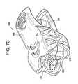
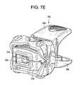
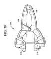
- FIGS. 7 a - 7 jdisclose instruments, devices and methods of using the present invention.
- a cervical motion disc insertercomprising:
- the distal end portion of the shaftis integral with the proximal end portion of the shaft.
- the first and second projectionsare disposed at the distal end of the inserter and are adapted to engage mating attachment surfaces of a cervical motion disc. Thus, they act together as a set of jaws 30 (as shown in FIG. 3 ) that can open and shut by virtue of the transverse translation afforded by the inserter, and thereby clamp and release the proximal end portion of the cervical motion disc.
- FIGS. 4 and 5An example of this mating engagement is shown in FIGS. 4 and 5 . As shown in FIGS. 4 and 5 , it is preferred that substantially the entire distal end surface of the both the longitudinal shaft and engagement element are adapted to mate with the proximal end surface of the cervical motion disc.
- the distal end portion of the longitudinal shaftfurther comprises a first transverse surface 9 extending transversely from the first medial surface and located at the proximal end of the first medial surface
- the engagement elementcomprises a second transverse surface 33 extending transversely from the second medial surface and located at the proximal end of the second medial surface.
- the second transverse surface of the engagement elementslidably translates on the first transverse surface of the distal end portion of the longitudinal shaft to provide transverse translation of the engagement element.
- the transverse surface of the distal end portion of the longitudinal shafthas a recess 45 for closely receiving a projection 46 of the transverse surface of the engagement element.
- the recesshas a width that is substantially similar to the width of the transverse surface of the engagement element, but has a length that is slightly longer than the transverse surface of the engagement element, thereby guiding the desired transverse translation.
- the first medial surface of the distal end portion of the longitudinal shaftfurther comprises a second recess 7 and the engagement element further comprises a flange 49 having a substantially cylindrical surface 51 extending from the second medial surface and a compression spring 53 received upon the substantially cylindrical surface of the flange, wherein the flange and compression spring of the engagement element are received within the second recess of the first medial surface of the distal end portion of the longitudinal shaft.
- the first function of the compression springis to provide a first “open jaw” configuration for the distal end portion of the inserter, as shown in FIG. 6 .
- the open jaw configurationallows the surgeon to place the jaw of the inserter around the proximal end portion of the cervical motion disc.
- the second function of the compression springis to allow a second “closed jaw” configuration for the distal end portion of the inserter when the annular component 55 is slid over the lateral surface of the distal end portion of the inserter, as shown in FIG. 5 .
- the closed jaw configurationallows the surgeon to clasp the jaw of the inserter upon the proximal end portion of the cervical motion disc.
- the surgeonmay transfer the motion disc to the patient and inserter the motion disc into the patient's cervical disc space.
- the surgeonmay withdraw the annular component from the inserter, thereby releasing the jaw to its open configuration and allowing removal of the inserter from the patient.
- the distal end portion of the longitudinal shaftfurther comprises a first lateral surface 57
- the engagement elementfurther comprises a second lateral surface 59
- the first lateral surfaceis disposed essentially parallel to the second lateral surface.
- the parallel nature of the lateral surfaces of the distal end portion of the inserterallows the annular component to have a simple cylindrical inner diameter, as the cylindrical inner surface of the annular component will align itself to the parallel disposition of the lateral surfaces.
- the parallel nature of the lateral surfacesalso allows insertion of the inserter through a minimum diameter portal in the patient's neck.
- FIGS. 5 and 6The open and closed nature of the jaws as a function of the annular component position is demonstrated in FIGS. 5 and 6 , wherein the first and second lateral surfaces define a first distance therebetween when the compression spring is relaxed ( FIG. 6 ) and a second distance therebetween when the compression spring is compressed ( FIG. 5 ), and wherein the inserter further comprises an annular component 55 disposed around the first and second lateral surfaces, the annular component having an inner diameter no greater than the first distance.
- a proximal portion of the first lateral surfaceforms a first chamfer 61
- the second medial surface and second lateral surfaceintersect to form a second chamfer 63
- the annular componenthas a tapered distal end chamfer 65 that narrows to a lateral point 67 .
- the angle of the chamfers on the shaft and engagement elementis substantially equal to the angle of the chamfer upon the distal end of the annular component. The equality of angles is preferable for two reasons. First, it allows for a more smooth engagement of the components and thereby reduces wear.
- the chamfer at the distal end of the annular componentcan press down upon the chamfers of the shaft and engagement element as it advances distally, and thereby push the engagement element medially towards the first medial surface of the shaft.
- This medial translation of the engagement elementwill desirably change the jaw configuration from an open to a closed configuration.
- the distance between the chamfers in the open jaw configurationis substantially similar to the inner diameter of the annular component.
- FIG. 5discloses the distal end portion of the inserter clasped upon the proximal end portion of a cervical motion disc.
- FIG. 5discloses an assembly for use in cervical disc surgery, comprising:
- the attachment surface of the cervical motion discpreferably comprises a base surface 77 , a neck region 79 extending proximally from the base surface, and an enlarged head region 81 formed proximally upon the neck region. Because the neck region is thinner than the more proximal and distal regions of the prosthetic disc, the neck region of the cervical motion disc defines bilateral grooves 83 . Accordingly, the first and second projections of the inserter engage the attachment surface of the cervical motion disc in a bilateral tongue-and-groove configuration at the level of the neck region.
- the detailed structure of the inserterincluding but not limited to the trigger mechanism, is the same as that described in US Patent Publication No. 2005-0143749 (Zalenski), the specification of which is incorporated by reference in its entirety,
- a useropens implant clip 300 by depressing and holding opposite portions of shells 306 , 308 at opposite ends of spring 302 ( FIG. 7 d ) to an open position (as shown in FIG. 7 f ).
- Opened clip 300is placed over a selected artificial disc 330 , causing implant holders 312 , 318 to engage artificial disc 330 when shells 306 , 308 are released.
- the useraligns the jaws 160 of implantation instrument 100 with alignment window 325 on implant clip 300 .
- the usersqueezes trigger mechanism 120 on implantation inserter 100 , thereby causing projections 162 to be inserted over engagement grooves 906 on artificial disc 900 (as shown in FIG. 7 g ).
- FIG. 7 ithere is a slightly different inserter (without the annular component) performing the same function.
- the userreleases trigger mechanism 120 , causing projections 162 to engage engagement grooves 906 on artificial disc 900 ( FIG. 7 g ).
- the userremoves implant clip 300 from artificial disc 900 by opening and removing implant clip 300 from the now engaged artificial disc 900 , as shown in FIG. 7 j.
- distraction instrument 950is inserted over pins (not shown) that are secured into vertebral bodies 962 , 964 .
- Artificial disc 330is passed between the forks of distraction instrument 950 using implantation inserter 100 (as shown in FIG. 7 a ).
- the usersqueezes trigger mechanism 120 ( FIG. 7 a ) which releases artificial disc 330 in prepared disc space 970 .
- the usercan determine the desired position by observing cephalad markers 168 ( FIGS. 7 c - d ) located on a surface of the jaws 160 .
- implantation instrument 100can include a depth control member 173 ( FIG. 7 a ) such that artificial disc 330 can be inserted into prepared disc space 970 at a predetermined depth.
Landscapes
- Health & Medical Sciences (AREA)
- Transplantation (AREA)
- Engineering & Computer Science (AREA)
- Biomedical Technology (AREA)
- Orthopedic Medicine & Surgery (AREA)
- Oral & Maxillofacial Surgery (AREA)
- Physical Education & Sports Medicine (AREA)
- Cardiology (AREA)
- Neurology (AREA)
- Heart & Thoracic Surgery (AREA)
- Vascular Medicine (AREA)
- Life Sciences & Earth Sciences (AREA)
- Animal Behavior & Ethology (AREA)
- General Health & Medical Sciences (AREA)
- Public Health (AREA)
- Veterinary Medicine (AREA)
- Prostheses (AREA)
Abstract
Description
- a. a longitudinal shaft having a distal end portion comprising
- i. a first medial surface having a first recess therein,
- ii. a first transverse surface extending transversely from the medial surface, and
- iii. a distal end forming a first projection, and
- b. an engagement element comprising:
- i. a second medial surface opposing the first medial surface of the distal end portion of the longitudinal shaft,
- ii. an alignment pin extending transversely from the second medial surface and slidably received within the first recess,
- iii. a distal end forming a second projection.
- a. a longitudinal shaft having a distal end portion comprising
- a) a longitudinal shaft having a distal end portion comprising a first transverse surface and a first projection,
- b) an engagement element comprising a distal end portion comprising a second transverse surface and a second projection, and
- c) means for providing relative translation of the first transverse upon the second transverse surface.
- a) a prosthetic cervical motion disc having a proximal end having an attachment surface, and
- b) the inserter of claim10,
wherein the first and second projections engage the attachment surface of the cervical motion disc.
- a) a longitudinal shaft having a distal end portion comprising a first transverse surface and a first projection,
- b) an engagement element comprising a distal end portion comprising a second transverse surface and a second projection,
wherein the first transverse surface is adapted to translate upon the second transverse surface and thereby adjust a distance between the first and second projections.
- a. a longitudinal shaft having a distal end portion comprising a first medial surface and a first projection,
- b. an engagement element comprising a distal end portion comprising a second medial surface and a second projection,
wherein the first medial surface opposes the second medial surface,
wherein the distal portion of the longitudinal shaft and the distal portion of the engagement element form a set of spring-loaded jaws.
- a) a prosthetic cervical motion disc comprising a proximal end having an attachment surface, and
- b) a cervical motion disc inserter comprising:
- i) a longitudinal shaft having a distal end portion comprising a first medial surface and a first projection,
- ii) an engagement element comprising a distal end portion comprising a second medial surface and a second projection,
wherein the first medial surface opposes the second medial surface,
wherein the distal portion of the longitudinal shaft and the distal portion of the engagement element form a set of spring-loaded jaws, and
wherein the first and second projections engage the attachment surface of the cervical motion disc.
- a) a prosthetic cervical motion disc comprising a proximal end having an attachment surface, and
- b) an adjustable wrench having a set of spring-loaded jaws,
wherein the jaws engage the attachment surface of the cervical motion disc.
- a) a
longitudinal shaft 1 having aproximal end portion 2, and adistal end portion 3 comprising- i. a first
medial surface 5 having afirst recess 97 therein, - ii. a first
transverse surface 9 extending transversely from the medial surface, and - iii. a
distal end 11 forming afirst projection 13, and
- i. a first
- b) an
engagement element 21 comprising:- i. a second
medial surface 23 opposing the first medial surface of the distal end portion of the longitudinal shaft, - ii. an
alignment pin 25 extending transversely from the second medial surface and slidably received within the first recess, - iii. a
distal end 27 forming asecond projection 29.
- i. a second
- a) a
- a) a prosthetic
cervical motion disc 71 having aproximal end 73 having anattachment surface 75, and - b) a distal portion of the inserter of the present invention,
wherein the first and second projections of the inserter engage the attachment surface of the cervical motion disc.
- a) a prosthetic
Claims (8)
Priority Applications (1)
| Application Number | Priority Date | Filing Date | Title |
|---|---|---|---|
| US12/414,591US8906033B2 (en) | 2009-03-30 | 2009-03-30 | Cervical motion disc inserter |
Applications Claiming Priority (1)
| Application Number | Priority Date | Filing Date | Title |
|---|---|---|---|
| US12/414,591US8906033B2 (en) | 2009-03-30 | 2009-03-30 | Cervical motion disc inserter |
Publications (2)
| Publication Number | Publication Date |
|---|---|
| US20100249795A1 US20100249795A1 (en) | 2010-09-30 |
| US8906033B2true US8906033B2 (en) | 2014-12-09 |
Family
ID=42785177
Family Applications (1)
| Application Number | Title | Priority Date | Filing Date |
|---|---|---|---|
| US12/414,591Active2031-04-06US8906033B2 (en) | 2009-03-30 | 2009-03-30 | Cervical motion disc inserter |
Country Status (1)
| Country | Link |
|---|---|
| US (1) | US8906033B2 (en) |
Cited By (2)
| Publication number | Priority date | Publication date | Assignee | Title |
|---|---|---|---|---|
| US9301853B2 (en) | 2010-04-09 | 2016-04-05 | DePuy Synthes Products, Inc. | Holder for implantation and extraction of prosthesis |
| US11344428B2 (en) | 2017-12-14 | 2022-05-31 | Simplify Medical Pty Ltd | Intervertebral prosthesis |
Families Citing this family (11)
| Publication number | Priority date | Publication date | Assignee | Title |
|---|---|---|---|---|
| US8123757B2 (en) | 2003-12-31 | 2012-02-28 | Depuy Spine, Inc. | Inserter instrument and implant clip |
| US8142441B2 (en)* | 2008-10-16 | 2012-03-27 | Aesculap Implant Systems, Llc | Surgical instrument and method of use for inserting an implant between two bones |
| US8591587B2 (en) | 2007-10-30 | 2013-11-26 | Aesculap Implant Systems, Llc | Vertebral body replacement device and method for use to maintain a space between two vertebral bodies within a spine |
| US11224521B2 (en) | 2008-06-06 | 2022-01-18 | Providence Medical Technology, Inc. | Cervical distraction/implant delivery device |
| US9592131B2 (en)* | 2010-01-22 | 2017-03-14 | Frontier Medical Devices, Inc. | Apparatus and method for stabilizing adjacent bone portions |
| US8858636B2 (en) | 2010-04-09 | 2014-10-14 | DePuy Synthes Products, LLC | Intervertebral implant |
| FR2981264B1 (en)* | 2011-10-17 | 2013-11-29 | Osteal Medical Lab | INTERVERTEBRAL IMPLANT GRIPPER, KIT AND MANIPULATION ASSEMBLY THEREFOR |
| US9034043B2 (en)* | 2012-02-03 | 2015-05-19 | Zimmer Spine, Inc. | Intervertebral implant and insertion instrument |
| ES2544274T3 (en)* | 2012-10-24 | 2015-08-28 | Waldemar Link Gmbh & Co. Kg | Support for a medical implant |
| EP3986336A4 (en)* | 2019-06-21 | 2023-07-19 | Providence Medical Technology, Inc. | SPINAL FACET JOINT IMPLANT AND RELATED INSTRUMENTS |
| US11452618B2 (en) | 2019-09-23 | 2022-09-27 | Dimicron, Inc | Spinal artificial disc removal tool |
Citations (137)
| Publication number | Priority date | Publication date | Assignee | Title |
|---|---|---|---|---|
| US132057A (en)* | 1872-10-08 | Improvement in adjustable slide-wrenches | ||
| US1539987A (en)* | 1924-02-11 | 1925-06-02 | John A Bell | Adjustable wrench |
| US3141583A (en) | 1962-03-23 | 1964-07-21 | William L Brickson | Injection gun |
| US3752161A (en) | 1971-08-02 | 1973-08-14 | Minnesota Mining & Mfg | Fluid operated surgical tool |
| US3835860A (en) | 1973-06-21 | 1974-09-17 | H Garretson | Surgical bone punch |
| US4367746A (en) | 1979-12-11 | 1983-01-11 | Derechinsky Victor E | Clip-holder instrument for clipping blood vessels |
| US4512345A (en) | 1982-09-30 | 1985-04-23 | United States Surgical Corporation | Surgical clip applying apparatus, and clips and clip train for use therein |
| US4592347A (en)* | 1983-10-11 | 1986-06-03 | Mahruki Nimetullah M T | Retraction device |
| US4759766A (en) | 1984-09-04 | 1988-07-26 | Humboldt-Universitaet Zu Berlin | Intervertebral disc endoprosthesis |
| FR2636227A1 (en) | 1988-09-09 | 1990-03-16 | Fabrication Materiel Orthopedi | Inter-spinal-body device for holding a normal spacing between two vertebrae |
| US5018412A (en)* | 1988-04-25 | 1991-05-28 | Wylie Iii Albert A | Open-end ratchet wrench |
| US5222973A (en)* | 1992-03-09 | 1993-06-29 | Sharpe Endosurgical Corporation | Endoscopic grasping tool surgical instrument |
| EP0333990B1 (en) | 1988-03-23 | 1993-07-21 | Waldemar Link (GmbH & Co.) | Surgical instrument set |
| US5236460A (en) | 1990-02-12 | 1993-08-17 | Midas Rex Pneumatic Tools, Inc. | Vertebral body prosthesis |
| US5258031A (en) | 1992-01-06 | 1993-11-02 | Danek Medical | Intervertebral disk arthroplasty |
| US5300081A (en) | 1992-10-09 | 1994-04-05 | United States Surgical Corporation | Surgical clip applier having clip advancement control |
| US5314477A (en) | 1990-03-07 | 1994-05-24 | J.B.S. Limited Company | Prosthesis for intervertebral discs and instruments for implanting it |
| US5360430A (en) | 1993-07-29 | 1994-11-01 | Lin Chih I | Intervertebral locking device |
| US5370697A (en) | 1992-04-21 | 1994-12-06 | Sulzer Medizinaltechnik Ag | Artificial intervertebral disk member |
| US5383888A (en)* | 1992-02-12 | 1995-01-24 | United States Surgical Corporation | Articulating endoscopic surgical apparatus |
| US5401269A (en) | 1992-03-13 | 1995-03-28 | Waldemar Link Gmbh & Co. | Intervertebral disc endoprosthesis |
| US5425773A (en) | 1992-01-06 | 1995-06-20 | Danek Medical, Inc. | Intervertebral disk arthroplasty device |
| US5431654A (en) | 1991-09-30 | 1995-07-11 | Stryker Corporation | Bone cement injector |
| US5431658A (en) | 1994-02-14 | 1995-07-11 | Moskovich; Ronald | Facilitator for vertebrae grafts and prostheses |
| US5443514A (en) | 1993-10-01 | 1995-08-22 | Acromed Corporation | Method for using spinal implants |
| US5458641A (en) | 1993-09-08 | 1995-10-17 | Ramirez Jimenez; Juan J. | Vertebral body prosthesis |
| US5486185A (en)* | 1989-01-30 | 1996-01-23 | Dexide, Inc. | Surgical apparatus |
| US5505732A (en) | 1988-06-13 | 1996-04-09 | Michelson; Gary K. | Apparatus and method of inserting spinal implants |
| US5507816A (en) | 1991-12-04 | 1996-04-16 | Customflex Limited | Spinal vertebrae implants |
| FR2717068B1 (en) | 1994-03-14 | 1996-04-26 | Biomat | Vertebral interbody fusion cage. |
| US5591170A (en) | 1994-10-14 | 1997-01-07 | Genesis Orthopedics | Intramedullary bone cutting saw |
| EP0535973B1 (en) | 1991-10-04 | 1997-03-12 | JOHNSON & JOHNSON ORTHOPAEDICS, INC. | An acetabular cup inserter |
| US5676701A (en) | 1993-01-14 | 1997-10-14 | Smith & Nephew, Inc. | Low wear artificial spinal disc |
| WO1997038634A1 (en) | 1996-04-18 | 1997-10-23 | Applied Medical Resources Corporation | Malleable clip applier and method |
| US5683465A (en) | 1996-03-18 | 1997-11-04 | Shinn; Gary Lee | Artificial intervertebral disk prosthesis |
| US5782832A (en) | 1996-10-01 | 1998-07-21 | Surgical Dynamics, Inc. | Spinal fusion implant and method of insertion thereof |
| US5782830A (en) | 1995-10-16 | 1998-07-21 | Sdgi Holdings, Inc. | Implant insertion device |
| EP0630615B1 (en) | 1993-06-16 | 1998-07-29 | Lerch, Karl-Dieter, Dr. med. | Set for treatment of vessel deformities |
| US5797927A (en) | 1995-09-22 | 1998-08-25 | Yoon; Inbae | Combined tissue clamping and suturing instrument |
| US5851207A (en) | 1997-07-01 | 1998-12-22 | Synthes (U.S.A.) | Freely separable surgical drill guide and plate |
| US5873886A (en) | 1995-04-04 | 1999-02-23 | United States Surgical Corporation | Surgical cutting apparatus |
| US5895428A (en) | 1996-11-01 | 1999-04-20 | Berry; Don | Load bearing spinal joint implant |
| US5899941A (en) | 1997-12-09 | 1999-05-04 | Chubu Bearing Kabushiki Kaisha | Artificial intervertebral disk |
| US5931849A (en) | 1997-05-06 | 1999-08-03 | Visco | Modular surgery device for endoscopic surgery and standard surgery |
| US5938678A (en) | 1997-06-11 | 1999-08-17 | Endius Incorporated | Surgical instrument |
| US5989291A (en) | 1998-02-26 | 1999-11-23 | Third Millennium Engineering, Llc | Intervertebral spacer device |
| US6019792A (en) | 1998-04-23 | 2000-02-01 | Cauthen Research Group, Inc. | Articulating spinal implant |
| US6063121A (en) | 1998-07-29 | 2000-05-16 | Xavier; Ravi | Vertebral body prosthesis |
| US6099550A (en) | 1989-12-05 | 2000-08-08 | Yoon; Inbae | Surgical instrument having jaws and an operating channel and method for use thereof |
| US6110179A (en) | 1998-03-02 | 2000-08-29 | Benoist Girard Sas | Prosthesis inserter |
| US6113637A (en) | 1998-10-22 | 2000-09-05 | Sofamor Danek Holdings, Inc. | Artificial intervertebral joint permitting translational and rotational motion |
| US6113605A (en) | 1998-03-02 | 2000-09-05 | Benoist Girard & Cie | Prosthesis inserter |
| US6146421A (en) | 1997-08-04 | 2000-11-14 | Gordon, Maya, Roberts And Thomas, Number 1, Llc | Multiple axis intervertebral prosthesis |
| US6159215A (en) | 1997-12-19 | 2000-12-12 | Depuy Acromed, Inc. | Insertion instruments and method for delivering a vertebral body spacer |
| US6174311B1 (en) | 1998-10-28 | 2001-01-16 | Sdgi Holdings, Inc. | Interbody fusion grafts and instrumentation |
| US6179874B1 (en) | 1998-04-23 | 2001-01-30 | Cauthen Research Group, Inc. | Articulating spinal implant |
| US6228118B1 (en) | 1997-08-04 | 2001-05-08 | Gordon, Maya, Roberts And Thomas, Number 1, Llc | Multiple axis intervertebral prosthesis |
| US6227079B1 (en)* | 2000-01-20 | 2001-05-08 | Kuo Chen Liu | Self adjusting tool |
| US6261296B1 (en) | 1998-10-02 | 2001-07-17 | Synthes U.S.A. | Spinal disc space distractor |
| US6296665B1 (en) | 2000-03-20 | 2001-10-02 | Electro-Biology, Inc. | Method and apparatus for spinal fixation |
| US6319257B1 (en)* | 1999-12-20 | 2001-11-20 | Kinamed, Inc. | Inserter assembly |
| US6328746B1 (en) | 1998-08-06 | 2001-12-11 | Michael A. Gambale | Surgical screw and driver system |
| WO2001062136A3 (en) | 2000-02-24 | 2002-02-21 | Stryker Instr | Bioabsorbable plates, fasteners, tools and method of using same |
| US6358268B1 (en) | 2000-03-06 | 2002-03-19 | Robert B. Hunt | Surgical instrument |
| US20020035400A1 (en) | 2000-08-08 | 2002-03-21 | Vincent Bryan | Implantable joint prosthesis |
| US6368350B1 (en) | 1999-03-11 | 2002-04-09 | Sulzer Spine-Tech Inc. | Intervertebral disc prosthesis and method |
| US6371986B1 (en) | 1998-10-27 | 2002-04-16 | George W. Bagby | Spinal fusion device, bone joining implant, and vertebral fusion implant |
| US6375682B1 (en) | 2001-08-06 | 2002-04-23 | Lewis W. Fleischmann | Collapsible, rotatable and expandable spinal hydraulic prosthetic device |
| US6395034B1 (en) | 1999-11-24 | 2002-05-28 | Loubert Suddaby | Intervertebral disc prosthesis |
| US6416551B1 (en) | 1999-05-21 | 2002-07-09 | Waldemar Link (Gmbh & Co.) | Intervertebral endoprosthesis with a toothed connection plate |
| US20020111682A1 (en) | 2001-02-15 | 2002-08-15 | Ralph James D. | Intervertebral spacer device having a radially thinning belleville spring |
| US20020111685A1 (en) | 2001-02-15 | 2002-08-15 | Ralph James D. | Intervertebral spacer device utilizing a spirally slotted belleville washer having radially spaced concentric grooves |
| US20020111687A1 (en) | 2001-02-15 | 2002-08-15 | Ralph James D. | Intervertebral spacer device utilizing a belleville washer having radially extending grooves |
| US20020111684A1 (en) | 2001-02-15 | 2002-08-15 | Ralph James D. | Intervertebral spacer device utilizing a belleville washer having radially spaced concentric grooves |
| US20020111686A1 (en) | 2001-02-15 | 2002-08-15 | Ralph James D. | Intervertebral spacer device utilizing a spirally slotted belleville washer and a rotational mounting |
| US20020111683A1 (en) | 2001-02-15 | 2002-08-15 | Ralph James D. | Intervertebral spacer device utilizing a spirally slotted belleville washer having radially extending grooves |
| US20020111679A1 (en) | 1998-10-20 | 2002-08-15 | Zucherman James F. | Apparatus and method for determining implant size |
| US20020111681A1 (en) | 2001-02-15 | 2002-08-15 | Ralph James D. | Intervertebral spacer device having a radially thinning slotted belleville spring |
| US20020116009A1 (en) | 2000-05-08 | 2002-08-22 | Fraser Robert D. | Medical installation tool |
| US6439439B1 (en) | 2001-01-12 | 2002-08-27 | Telios Orthopedic Systems, Inc. | Bone cement delivery apparatus and hand-held fluent material dispensing apparatus |
| US6440142B1 (en) | 2001-04-27 | 2002-08-27 | Third Millennium Engineering, Llc | Femoral ring loader |
| US20020128714A1 (en) | 1999-06-04 | 2002-09-12 | Mark Manasas | Orthopedic implant and method of making metal articles |
| US20020128715A1 (en) | 2000-08-08 | 2002-09-12 | Vincent Bryan | Implantable joint prosthesis |
| US20020161366A1 (en) | 2000-12-29 | 2002-10-31 | Bruce Robie | Instrument system for preparing a disc space between adjacent vertebral bodies to receive a repair device |
| US20020173813A1 (en) | 2001-04-05 | 2002-11-21 | Peterson Francis C. | Circumferential resecting reamer tool |
| US6517580B1 (en) | 2000-03-03 | 2003-02-11 | Scient'x Societe A Responsabilite Limited | Disk prosthesis for cervical vertebrae |
| US6517544B1 (en) | 1998-06-09 | 2003-02-11 | Gary K. Michelson | Device and method for preparing a space between adjacent vertebrae to receive an insert |
| US20030033016A1 (en) | 2001-08-07 | 2003-02-13 | Gyrus Group Plc | Implant sheath |
| US6520996B1 (en) | 1999-06-04 | 2003-02-18 | Depuy Acromed, Incorporated | Orthopedic implant |
| US6524312B2 (en) | 2000-01-06 | 2003-02-25 | Spinal Concepts, Inc. | Instrument and method for implanting an interbody fusion device |
| US20030040802A1 (en) | 2001-07-16 | 2003-02-27 | Errico Joseph P. | Artificial intervertebral disc having limited rotation using a captured ball and socket joint with a solid ball and compression locking post |
| US6527804B1 (en) | 1998-12-11 | 2003-03-04 | Dimso (Distribution Medicale Du Sud-Quest) | Intervertebral disk prosthesis |
| US20030060687A1 (en) | 2001-09-25 | 2003-03-27 | Kleeman Thomas J. | Methods and devices for inserting and manipulating surgical instruments |
| US20030069586A1 (en) | 2001-07-16 | 2003-04-10 | Errico Joseph P. | Instrumentation and methods for use in implanting an artificial intervertebral disc |
| US20030069643A1 (en) | 2001-07-16 | 2003-04-10 | Ralph James D. | Tension bearing artificial disc providing a centroid of motion centrally located within an intervertebral space |
| US20030074076A1 (en) | 1999-10-08 | 2003-04-17 | Ferree Bret A. | Artificial intervertebral disc replacements with endplates |
| US20030074066A1 (en) | 2001-07-16 | 2003-04-17 | Errico Joseph P. | Artificial intervertebral disc having limited rotation using a captured ball and socket joint with a solid ball, a retaining cap, and an interference pin |
| US20030078665A1 (en) | 2001-10-18 | 2003-04-24 | Ralph James D. | Intervertebral spacer device having a multi-pronged domed spring |
| US20030083747A1 (en) | 2001-10-30 | 2003-05-01 | Osteotech, Inc. | Bone implant and isertion tools |
| US6562074B2 (en) | 2001-10-17 | 2003-05-13 | Medicinelodge, Inc. | Adjustable bone fusion implant and method |
| US6579320B1 (en) | 1998-12-11 | 2003-06-17 | Stryker Spine | Intervertebral disc prosthesis with contact blocks |
| US20030135277A1 (en) | 2001-11-26 | 2003-07-17 | Sdgi Holdings, Inc. | Implantable joint prosthesis and associated instrumentation |
| US20030135275A1 (en) | 2001-11-09 | 2003-07-17 | Javier Garcia | Instruments and methods for inserting a spinal implant |
| US20030135278A1 (en) | 2002-01-17 | 2003-07-17 | Concept Matrix, Llc | Intervertebral disk prosthesis |
| US6599295B1 (en) | 1998-04-21 | 2003-07-29 | Tornier Sa | Device for setting and removing an implant such as a suture anchor |
| US6599294B2 (en) | 1999-01-30 | 2003-07-29 | Aesculap Ag & Co. Kg | Surgical instrument for introducing intervertebral implants |
| US6599292B1 (en) | 1998-01-05 | 2003-07-29 | Tegementa, L.L.C. | Distraction device for vertebral disc procedures and method of distracting |
| US20030149482A1 (en) | 1988-06-28 | 2003-08-07 | Sofamor Danek Group, Inc. | Artificial spinal fusion implants |
| US20030171813A1 (en) | 2002-03-05 | 2003-09-11 | P. Douglas Kiester | Method and apparatus for providing an expandable spinal fusion cage |
| US20030199872A1 (en) | 2002-04-17 | 2003-10-23 | Stryker Spine | Rod persuader |
| US6648891B2 (en) | 2001-09-14 | 2003-11-18 | The Regents Of The University Of California | System and method for fusing spinal vertebrae |
| US20030216744A1 (en) | 1999-10-18 | 2003-11-20 | Sulzer Spine-Tech Inc. | Spinal surgery instruments and methods |
| US6652533B2 (en) | 2001-09-20 | 2003-11-25 | Depuy Acromed, Inc. | Medical inserter tool with slaphammer |
| US6663637B2 (en) | 2001-01-02 | 2003-12-16 | Robert A Dixon | Vertebral distraction stabilizer |
| US6692501B2 (en) | 2000-12-14 | 2004-02-17 | Gary K. Michelson | Spinal interspace shaper |
| US6712818B1 (en) | 1997-02-11 | 2004-03-30 | Gary K. Michelson | Method for connecting adjacent vertebral bodies of a human spine with a plating system |
| US6740087B2 (en) | 1999-04-06 | 2004-05-25 | Benjamin D. Knox | Spinal fusion instrumentation system |
| US20040102850A1 (en)* | 2002-11-25 | 2004-05-27 | Shepard Yolanda Denise | Cortical and cancellous allograft spacer |
| US20040176773A1 (en) | 2003-03-06 | 2004-09-09 | Rafail Zubok | Instrumentation and methods for use in implanting a cervical disc replacement device |
| US20040215198A1 (en) | 2003-04-28 | 2004-10-28 | Spine Solutions, Inc. | Instruments and method for preparing an intervertebral space for receiving an artificial disc implant |
| US20040225295A1 (en) | 2001-07-16 | 2004-11-11 | Rafail Zubok | Wedge ramp distractor and related methods for use in implanting artificial intervertebral discs |
| US20050015094A1 (en) | 2003-07-15 | 2005-01-20 | Cervitech, Inc. | Arrangement of a cervical prosthesis and insertion instrument |
| US20050015095A1 (en) | 2003-07-15 | 2005-01-20 | Cervitech, Inc. | Insertion instrument for cervical prostheses |
| US20050021042A1 (en) | 2003-07-21 | 2005-01-27 | Theirry Marnay | Instruments and method for inserting an intervertebral implant |
| US20050021040A1 (en) | 2003-07-21 | 2005-01-27 | Rudolf Bertagnoli | Vertebral retainer-distracter and method of using same |
| US20050027300A1 (en) | 2003-03-31 | 2005-02-03 | Depuy Spine, Inc. | Method and apparatus for artificial disc insertion |
| US20050033428A1 (en) | 2003-08-04 | 2005-02-10 | Cervitech, Inc. | Cervical prosthesis with insertion instrument |
| US20050038511A1 (en) | 2003-08-15 | 2005-02-17 | Martz Erik O. | Transforaminal lumbar interbody fusion (TLIF) implant, surgical procedure and instruments for insertion of spinal implant in a spinal disc space |
| US20050043740A1 (en) | 2003-08-20 | 2005-02-24 | Haid Regis W. | Technique and instrumentation for preparation of vertebral members |
| US20050043800A1 (en) | 2003-07-31 | 2005-02-24 | Paul David C. | Prosthetic spinal disc replacement |
| US20050055029A1 (en) | 2003-09-10 | 2005-03-10 | Sdgi Holdings, Inc. | Artificial spinal discs and associated implantation instruments and methods |
| US20050055031A1 (en) | 2003-09-10 | 2005-03-10 | Roy Lim | Devices and methods for inserting spinal implants |
| US20050143749A1 (en) | 2003-12-31 | 2005-06-30 | Depuy Spine, Inc. | Inserter instrument and implant clip |
| US7011683B2 (en)* | 2002-01-08 | 2006-03-14 | Patrick Antonelli | Attachment mechanism for middle ear prosthesis |
| US20080167680A1 (en)* | 2007-01-10 | 2008-07-10 | Voegele James W | Fingertip Surgical Instrument |
| US7608080B2 (en) | 2004-07-02 | 2009-10-27 | Warsaw Orthopedic, Inc. | Device for inserting implants |
| US7695478B2 (en)* | 2001-07-16 | 2010-04-13 | Spinecore, Inc. | Insertion tool for use with intervertebral spacers |
- 2009
- 2009-03-30USUS12/414,591patent/US8906033B2/enactiveActive
Patent Citations (163)
| Publication number | Priority date | Publication date | Assignee | Title |
|---|---|---|---|---|
| US132057A (en)* | 1872-10-08 | Improvement in adjustable slide-wrenches | ||
| US1539987A (en)* | 1924-02-11 | 1925-06-02 | John A Bell | Adjustable wrench |
| US3141583A (en) | 1962-03-23 | 1964-07-21 | William L Brickson | Injection gun |
| US3752161A (en) | 1971-08-02 | 1973-08-14 | Minnesota Mining & Mfg | Fluid operated surgical tool |
| US3835860A (en) | 1973-06-21 | 1974-09-17 | H Garretson | Surgical bone punch |
| US4367746A (en) | 1979-12-11 | 1983-01-11 | Derechinsky Victor E | Clip-holder instrument for clipping blood vessels |
| US4512345A (en) | 1982-09-30 | 1985-04-23 | United States Surgical Corporation | Surgical clip applying apparatus, and clips and clip train for use therein |
| US4592347A (en)* | 1983-10-11 | 1986-06-03 | Mahruki Nimetullah M T | Retraction device |
| US4759766A (en) | 1984-09-04 | 1988-07-26 | Humboldt-Universitaet Zu Berlin | Intervertebral disc endoprosthesis |
| EP0333990B1 (en) | 1988-03-23 | 1993-07-21 | Waldemar Link (GmbH & Co.) | Surgical instrument set |
| US5018412A (en)* | 1988-04-25 | 1991-05-28 | Wylie Iii Albert A | Open-end ratchet wrench |
| US5505732A (en) | 1988-06-13 | 1996-04-09 | Michelson; Gary K. | Apparatus and method of inserting spinal implants |
| US20030149482A1 (en) | 1988-06-28 | 2003-08-07 | Sofamor Danek Group, Inc. | Artificial spinal fusion implants |
| FR2636227A1 (en) | 1988-09-09 | 1990-03-16 | Fabrication Materiel Orthopedi | Inter-spinal-body device for holding a normal spacing between two vertebrae |
| US5486185A (en)* | 1989-01-30 | 1996-01-23 | Dexide, Inc. | Surgical apparatus |
| US6099550A (en) | 1989-12-05 | 2000-08-08 | Yoon; Inbae | Surgical instrument having jaws and an operating channel and method for use thereof |
| US5236460A (en) | 1990-02-12 | 1993-08-17 | Midas Rex Pneumatic Tools, Inc. | Vertebral body prosthesis |
| US5314477A (en) | 1990-03-07 | 1994-05-24 | J.B.S. Limited Company | Prosthesis for intervertebral discs and instruments for implanting it |
| US5431654A (en) | 1991-09-30 | 1995-07-11 | Stryker Corporation | Bone cement injector |
| EP0535973B1 (en) | 1991-10-04 | 1997-03-12 | JOHNSON & JOHNSON ORTHOPAEDICS, INC. | An acetabular cup inserter |
| US5507816A (en) | 1991-12-04 | 1996-04-16 | Customflex Limited | Spinal vertebrae implants |
| US5562738A (en) | 1992-01-06 | 1996-10-08 | Danek Medical, Inc. | Intervertebral disk arthroplasty device |
| US5258031A (en) | 1992-01-06 | 1993-11-02 | Danek Medical | Intervertebral disk arthroplasty |
| US5425773A (en) | 1992-01-06 | 1995-06-20 | Danek Medical, Inc. | Intervertebral disk arthroplasty device |
| US5383888A (en)* | 1992-02-12 | 1995-01-24 | United States Surgical Corporation | Articulating endoscopic surgical apparatus |
| US5222973A (en)* | 1992-03-09 | 1993-06-29 | Sharpe Endosurgical Corporation | Endoscopic grasping tool surgical instrument |
| US5401269A (en) | 1992-03-13 | 1995-03-28 | Waldemar Link Gmbh & Co. | Intervertebral disc endoprosthesis |
| US5370697A (en) | 1992-04-21 | 1994-12-06 | Sulzer Medizinaltechnik Ag | Artificial intervertebral disk member |
| US5300081A (en) | 1992-10-09 | 1994-04-05 | United States Surgical Corporation | Surgical clip applier having clip advancement control |
| US5676701A (en) | 1993-01-14 | 1997-10-14 | Smith & Nephew, Inc. | Low wear artificial spinal disc |
| EP0630615B1 (en) | 1993-06-16 | 1998-07-29 | Lerch, Karl-Dieter, Dr. med. | Set for treatment of vessel deformities |
| US5360430A (en) | 1993-07-29 | 1994-11-01 | Lin Chih I | Intervertebral locking device |
| US5458641A (en) | 1993-09-08 | 1995-10-17 | Ramirez Jimenez; Juan J. | Vertebral body prosthesis |
| US5443514A (en) | 1993-10-01 | 1995-08-22 | Acromed Corporation | Method for using spinal implants |
| US5431658A (en) | 1994-02-14 | 1995-07-11 | Moskovich; Ronald | Facilitator for vertebrae grafts and prostheses |
| FR2717068B1 (en) | 1994-03-14 | 1996-04-26 | Biomat | Vertebral interbody fusion cage. |
| US5591170A (en) | 1994-10-14 | 1997-01-07 | Genesis Orthopedics | Intramedullary bone cutting saw |
| US5873886A (en) | 1995-04-04 | 1999-02-23 | United States Surgical Corporation | Surgical cutting apparatus |
| US5797927A (en) | 1995-09-22 | 1998-08-25 | Yoon; Inbae | Combined tissue clamping and suturing instrument |
| US5782830A (en) | 1995-10-16 | 1998-07-21 | Sdgi Holdings, Inc. | Implant insertion device |
| US6066174A (en)* | 1995-10-16 | 2000-05-23 | Sdgi Holdings, Inc. | Implant insertion device |
| US5683465A (en) | 1996-03-18 | 1997-11-04 | Shinn; Gary Lee | Artificial intervertebral disk prosthesis |
| WO1997038634A1 (en) | 1996-04-18 | 1997-10-23 | Applied Medical Resources Corporation | Malleable clip applier and method |
| US5782832A (en) | 1996-10-01 | 1998-07-21 | Surgical Dynamics, Inc. | Spinal fusion implant and method of insertion thereof |
| US5895428A (en) | 1996-11-01 | 1999-04-20 | Berry; Don | Load bearing spinal joint implant |
| US6712818B1 (en) | 1997-02-11 | 2004-03-30 | Gary K. Michelson | Method for connecting adjacent vertebral bodies of a human spine with a plating system |
| US5931849A (en) | 1997-05-06 | 1999-08-03 | Visco | Modular surgery device for endoscopic surgery and standard surgery |
| US5938678A (en) | 1997-06-11 | 1999-08-17 | Endius Incorporated | Surgical instrument |
| US5851207A (en) | 1997-07-01 | 1998-12-22 | Synthes (U.S.A.) | Freely separable surgical drill guide and plate |
| US6146421A (en) | 1997-08-04 | 2000-11-14 | Gordon, Maya, Roberts And Thomas, Number 1, Llc | Multiple axis intervertebral prosthesis |
| US6228118B1 (en) | 1997-08-04 | 2001-05-08 | Gordon, Maya, Roberts And Thomas, Number 1, Llc | Multiple axis intervertebral prosthesis |
| US5899941A (en) | 1997-12-09 | 1999-05-04 | Chubu Bearing Kabushiki Kaisha | Artificial intervertebral disk |
| US6159215A (en) | 1997-12-19 | 2000-12-12 | Depuy Acromed, Inc. | Insertion instruments and method for delivering a vertebral body spacer |
| US6599292B1 (en) | 1998-01-05 | 2003-07-29 | Tegementa, L.L.C. | Distraction device for vertebral disc procedures and method of distracting |
| US5989291A (en) | 1998-02-26 | 1999-11-23 | Third Millennium Engineering, Llc | Intervertebral spacer device |
| US6110179A (en) | 1998-03-02 | 2000-08-29 | Benoist Girard Sas | Prosthesis inserter |
| US6113605A (en) | 1998-03-02 | 2000-09-05 | Benoist Girard & Cie | Prosthesis inserter |
| US6599295B1 (en) | 1998-04-21 | 2003-07-29 | Tornier Sa | Device for setting and removing an implant such as a suture anchor |
| US6179874B1 (en) | 1998-04-23 | 2001-01-30 | Cauthen Research Group, Inc. | Articulating spinal implant |
| US6440168B1 (en) | 1998-04-23 | 2002-08-27 | Sdgi Holdings, Inc. | Articulating spinal implant |
| US6019792A (en) | 1998-04-23 | 2000-02-01 | Cauthen Research Group, Inc. | Articulating spinal implant |
| US6517544B1 (en) | 1998-06-09 | 2003-02-11 | Gary K. Michelson | Device and method for preparing a space between adjacent vertebrae to receive an insert |
| US6063121A (en) | 1998-07-29 | 2000-05-16 | Xavier; Ravi | Vertebral body prosthesis |
| US6328746B1 (en) | 1998-08-06 | 2001-12-11 | Michael A. Gambale | Surgical screw and driver system |
| US6261296B1 (en) | 1998-10-02 | 2001-07-17 | Synthes U.S.A. | Spinal disc space distractor |
| US20020111679A1 (en) | 1998-10-20 | 2002-08-15 | Zucherman James F. | Apparatus and method for determining implant size |
| US6652534B2 (en) | 1998-10-20 | 2003-11-25 | St. Francis Medical Technologies, Inc. | Apparatus and method for determining implant size |
| US20030187454A1 (en) | 1998-10-22 | 2003-10-02 | Gill Steven S. | Artificial intervertebral joint permitting translational and rotational motion |
| US6540785B1 (en) | 1998-10-22 | 2003-04-01 | Sdgi Holdings, Inc. | Artificial intervertebral joint permitting translational and rotational motion |
| US6113637A (en) | 1998-10-22 | 2000-09-05 | Sofamor Danek Holdings, Inc. | Artificial intervertebral joint permitting translational and rotational motion |
| US6371986B1 (en) | 1998-10-27 | 2002-04-16 | George W. Bagby | Spinal fusion device, bone joining implant, and vertebral fusion implant |
| US6174311B1 (en) | 1998-10-28 | 2001-01-16 | Sdgi Holdings, Inc. | Interbody fusion grafts and instrumentation |
| US6579320B1 (en) | 1998-12-11 | 2003-06-17 | Stryker Spine | Intervertebral disc prosthesis with contact blocks |
| US6527804B1 (en) | 1998-12-11 | 2003-03-04 | Dimso (Distribution Medicale Du Sud-Quest) | Intervertebral disk prosthesis |
| US6599294B2 (en) | 1999-01-30 | 2003-07-29 | Aesculap Ag & Co. Kg | Surgical instrument for introducing intervertebral implants |
| US6368350B1 (en) | 1999-03-11 | 2002-04-09 | Sulzer Spine-Tech Inc. | Intervertebral disc prosthesis and method |
| US6740087B2 (en) | 1999-04-06 | 2004-05-25 | Benjamin D. Knox | Spinal fusion instrumentation system |
| US6416551B1 (en) | 1999-05-21 | 2002-07-09 | Waldemar Link (Gmbh & Co.) | Intervertebral endoprosthesis with a toothed connection plate |
| US20020128714A1 (en) | 1999-06-04 | 2002-09-12 | Mark Manasas | Orthopedic implant and method of making metal articles |
| US6520996B1 (en) | 1999-06-04 | 2003-02-18 | Depuy Acromed, Incorporated | Orthopedic implant |
| US20030074076A1 (en) | 1999-10-08 | 2003-04-17 | Ferree Bret A. | Artificial intervertebral disc replacements with endplates |
| US20030216744A1 (en) | 1999-10-18 | 2003-11-20 | Sulzer Spine-Tech Inc. | Spinal surgery instruments and methods |
| US6395034B1 (en) | 1999-11-24 | 2002-05-28 | Loubert Suddaby | Intervertebral disc prosthesis |
| US6319257B1 (en)* | 1999-12-20 | 2001-11-20 | Kinamed, Inc. | Inserter assembly |
| US6524312B2 (en) | 2000-01-06 | 2003-02-25 | Spinal Concepts, Inc. | Instrument and method for implanting an interbody fusion device |
| US6616671B2 (en) | 2000-01-06 | 2003-09-09 | Spinal Concepts, Inc. | Instrument and method for implanting an interbody fusion device |
| US6227079B1 (en)* | 2000-01-20 | 2001-05-08 | Kuo Chen Liu | Self adjusting tool |
| WO2001062136A3 (en) | 2000-02-24 | 2002-02-21 | Stryker Instr | Bioabsorbable plates, fasteners, tools and method of using same |
| US6517580B1 (en) | 2000-03-03 | 2003-02-11 | Scient'x Societe A Responsabilite Limited | Disk prosthesis for cervical vertebrae |
| US6358268B1 (en) | 2000-03-06 | 2002-03-19 | Robert B. Hunt | Surgical instrument |
| US6296665B1 (en) | 2000-03-20 | 2001-10-02 | Electro-Biology, Inc. | Method and apparatus for spinal fixation |
| US20020116009A1 (en) | 2000-05-08 | 2002-08-22 | Fraser Robert D. | Medical installation tool |
| US20020128715A1 (en) | 2000-08-08 | 2002-09-12 | Vincent Bryan | Implantable joint prosthesis |
| US20020035400A1 (en) | 2000-08-08 | 2002-03-21 | Vincent Bryan | Implantable joint prosthesis |
| US6692501B2 (en) | 2000-12-14 | 2004-02-17 | Gary K. Michelson | Spinal interspace shaper |
| US20020161366A1 (en) | 2000-12-29 | 2002-10-31 | Bruce Robie | Instrument system for preparing a disc space between adjacent vertebral bodies to receive a repair device |
| US6663637B2 (en) | 2001-01-02 | 2003-12-16 | Robert A Dixon | Vertebral distraction stabilizer |
| US6439439B1 (en) | 2001-01-12 | 2002-08-27 | Telios Orthopedic Systems, Inc. | Bone cement delivery apparatus and hand-held fluent material dispensing apparatus |
| US20020111682A1 (en) | 2001-02-15 | 2002-08-15 | Ralph James D. | Intervertebral spacer device having a radially thinning belleville spring |
| US20020111684A1 (en) | 2001-02-15 | 2002-08-15 | Ralph James D. | Intervertebral spacer device utilizing a belleville washer having radially spaced concentric grooves |
| US20020111686A1 (en) | 2001-02-15 | 2002-08-15 | Ralph James D. | Intervertebral spacer device utilizing a spirally slotted belleville washer and a rotational mounting |
| US20020111683A1 (en) | 2001-02-15 | 2002-08-15 | Ralph James D. | Intervertebral spacer device utilizing a spirally slotted belleville washer having radially extending grooves |
| US20020111687A1 (en) | 2001-02-15 | 2002-08-15 | Ralph James D. | Intervertebral spacer device utilizing a belleville washer having radially extending grooves |
| US20020111681A1 (en) | 2001-02-15 | 2002-08-15 | Ralph James D. | Intervertebral spacer device having a radially thinning slotted belleville spring |
| US20020111685A1 (en) | 2001-02-15 | 2002-08-15 | Ralph James D. | Intervertebral spacer device utilizing a spirally slotted belleville washer having radially spaced concentric grooves |
| US20020173813A1 (en) | 2001-04-05 | 2002-11-21 | Peterson Francis C. | Circumferential resecting reamer tool |
| US6440142B1 (en) | 2001-04-27 | 2002-08-27 | Third Millennium Engineering, Llc | Femoral ring loader |
| US20020161375A1 (en) | 2001-04-27 | 2002-10-31 | Ralph James D. | Femoral ring loader |
| US20030074071A1 (en) | 2001-07-16 | 2003-04-17 | Errico Joseph P. | Artificial intervertebral disc having limited rotation using a captured ball and socket joint with a compression locking post and a solid ball having a protrusion |
| US20040167537A1 (en) | 2001-07-16 | 2004-08-26 | Errico Joseph P. | Artificial intervertebral disc trial having a controllably separable distal end |
| US20030074067A1 (en) | 2001-07-16 | 2003-04-17 | Errico Joseph P. | Artificial intervertebral disc having a captured ball and socket joint with a solid ball and compression locking post |
| US20030069643A1 (en) | 2001-07-16 | 2003-04-10 | Ralph James D. | Tension bearing artificial disc providing a centroid of motion centrally located within an intervertebral space |
| US20030074070A1 (en) | 2001-07-16 | 2003-04-17 | Errico Joseph P. | Artificial intervertebral disc having limited rotation using a captured ball and socket joint with a retaining cap and a solid ball having a protrusion |
| US20030074073A1 (en) | 2001-07-16 | 2003-04-17 | Errico Joseph P. | Artificial intervertebral disc having limited rotation using a captured ball and socket joint with a solid ball, a retaining cap, and an interference ball bearing |
| US20030074072A1 (en) | 2001-07-16 | 2003-04-17 | Errico Joseph P. | Artificial intervertebral disc having limited rotation using a captured ball and socket joint with a solid ball, a compression locking post, and an interference pin |
| US20030074069A1 (en) | 2001-07-16 | 2003-04-17 | Errico Joseph P. | Artificial intervertebral disc having a captured ball and socket joint with a solid ball and retaining cap |
| US20030074068A1 (en) | 2001-07-16 | 2003-04-17 | Errico Joseph P. | Artificial intervertebral disc having limited rotation using a captured ball and socket joint with a solid ball and retaining cap |
| US7695478B2 (en)* | 2001-07-16 | 2010-04-13 | Spinecore, Inc. | Insertion tool for use with intervertebral spacers |
| US20030069586A1 (en) | 2001-07-16 | 2003-04-10 | Errico Joseph P. | Instrumentation and methods for use in implanting an artificial intervertebral disc |
| US20040225295A1 (en) | 2001-07-16 | 2004-11-11 | Rafail Zubok | Wedge ramp distractor and related methods for use in implanting artificial intervertebral discs |
| US20040167534A1 (en) | 2001-07-16 | 2004-08-26 | Errico Joseph P. | Instrumentation for inserting and impacting an artificial intervertebral disc in an intervertebral space |
| US20030040802A1 (en) | 2001-07-16 | 2003-02-27 | Errico Joseph P. | Artificial intervertebral disc having limited rotation using a captured ball and socket joint with a solid ball and compression locking post |
| US20030074074A1 (en) | 2001-07-16 | 2003-04-17 | Errico Joseph P. | Artificial intervertebral disc having limited rotation using a captured ball and socket joint with a solid ball, a compression locking post, and an interference ball bearing |
| US20030074066A1 (en) | 2001-07-16 | 2003-04-17 | Errico Joseph P. | Artificial intervertebral disc having limited rotation using a captured ball and socket joint with a solid ball, a retaining cap, and an interference pin |
| US6375682B1 (en) | 2001-08-06 | 2002-04-23 | Lewis W. Fleischmann | Collapsible, rotatable and expandable spinal hydraulic prosthetic device |
| US20030033016A1 (en) | 2001-08-07 | 2003-02-13 | Gyrus Group Plc | Implant sheath |
| US6648891B2 (en) | 2001-09-14 | 2003-11-18 | The Regents Of The University Of California | System and method for fusing spinal vertebrae |
| US6652533B2 (en) | 2001-09-20 | 2003-11-25 | Depuy Acromed, Inc. | Medical inserter tool with slaphammer |
| US20030060687A1 (en) | 2001-09-25 | 2003-03-27 | Kleeman Thomas J. | Methods and devices for inserting and manipulating surgical instruments |
| US20030065395A1 (en) | 2001-10-01 | 2003-04-03 | Ralph James D. | Artificial intervertebral disc having a slotted belleville washer force restoring element |
| US6562074B2 (en) | 2001-10-17 | 2003-05-13 | Medicinelodge, Inc. | Adjustable bone fusion implant and method |
| US20030078666A1 (en) | 2001-10-18 | 2003-04-24 | Ralph James D. | Intervertebral spacer device having a slotted partial circular domed arch strip spring |
| US20030078664A1 (en) | 2001-10-18 | 2003-04-24 | Ralph James D. | Intervertebral spacer device having a domed arch shaped spring |
| US20030078665A1 (en) | 2001-10-18 | 2003-04-24 | Ralph James D. | Intervertebral spacer device having a multi-pronged domed spring |
| US20030083747A1 (en) | 2001-10-30 | 2003-05-01 | Osteotech, Inc. | Bone implant and isertion tools |
| US20030135275A1 (en) | 2001-11-09 | 2003-07-17 | Javier Garcia | Instruments and methods for inserting a spinal implant |
| US20030135277A1 (en) | 2001-11-26 | 2003-07-17 | Sdgi Holdings, Inc. | Implantable joint prosthesis and associated instrumentation |
| US7011683B2 (en)* | 2002-01-08 | 2006-03-14 | Patrick Antonelli | Attachment mechanism for middle ear prosthesis |
| US20030135278A1 (en) | 2002-01-17 | 2003-07-17 | Concept Matrix, Llc | Intervertebral disk prosthesis |
| US20030171813A1 (en) | 2002-03-05 | 2003-09-11 | P. Douglas Kiester | Method and apparatus for providing an expandable spinal fusion cage |
| US6660006B2 (en) | 2002-04-17 | 2003-12-09 | Stryker Spine | Rod persuader |
| US20030199872A1 (en) | 2002-04-17 | 2003-10-23 | Stryker Spine | Rod persuader |
| US20040102850A1 (en)* | 2002-11-25 | 2004-05-27 | Shepard Yolanda Denise | Cortical and cancellous allograft spacer |
| US20040176773A1 (en) | 2003-03-06 | 2004-09-09 | Rafail Zubok | Instrumentation and methods for use in implanting a cervical disc replacement device |
| US20050071013A1 (en) | 2003-03-06 | 2005-03-31 | Spinecore, Inc. | Instrumentation and methods for use in implanting a cervical disc replacement device |
| US20050027300A1 (en) | 2003-03-31 | 2005-02-03 | Depuy Spine, Inc. | Method and apparatus for artificial disc insertion |
| US20040215198A1 (en) | 2003-04-28 | 2004-10-28 | Spine Solutions, Inc. | Instruments and method for preparing an intervertebral space for receiving an artificial disc implant |
| US20050015095A1 (en) | 2003-07-15 | 2005-01-20 | Cervitech, Inc. | Insertion instrument for cervical prostheses |
| US20050015094A1 (en) | 2003-07-15 | 2005-01-20 | Cervitech, Inc. | Arrangement of a cervical prosthesis and insertion instrument |
| US20050021042A1 (en) | 2003-07-21 | 2005-01-27 | Theirry Marnay | Instruments and method for inserting an intervertebral implant |
| US20050021040A1 (en) | 2003-07-21 | 2005-01-27 | Rudolf Bertagnoli | Vertebral retainer-distracter and method of using same |
| US20050043800A1 (en) | 2003-07-31 | 2005-02-24 | Paul David C. | Prosthetic spinal disc replacement |
| US20050033428A1 (en) | 2003-08-04 | 2005-02-10 | Cervitech, Inc. | Cervical prosthesis with insertion instrument |
| US20050038511A1 (en) | 2003-08-15 | 2005-02-17 | Martz Erik O. | Transforaminal lumbar interbody fusion (TLIF) implant, surgical procedure and instruments for insertion of spinal implant in a spinal disc space |
| US20050043740A1 (en) | 2003-08-20 | 2005-02-24 | Haid Regis W. | Technique and instrumentation for preparation of vertebral members |
| US20050055098A1 (en) | 2003-09-10 | 2005-03-10 | Sdgi Holdings, Inc. | Artificial spinal discs and associated implantation and revision methods |
| US20050055031A1 (en) | 2003-09-10 | 2005-03-10 | Roy Lim | Devices and methods for inserting spinal implants |
| US20050055029A1 (en) | 2003-09-10 | 2005-03-10 | Sdgi Holdings, Inc. | Artificial spinal discs and associated implantation instruments and methods |
| US20050143749A1 (en) | 2003-12-31 | 2005-06-30 | Depuy Spine, Inc. | Inserter instrument and implant clip |
| US20080071293A1 (en) | 2003-12-31 | 2008-03-20 | Depuy Spine, Inc. | Inserter instrument and implant clip |
| US8123757B2 (en) | 2003-12-31 | 2012-02-28 | Depuy Spine, Inc. | Inserter instrument and implant clip |
| US7608080B2 (en) | 2004-07-02 | 2009-10-27 | Warsaw Orthopedic, Inc. | Device for inserting implants |
| US20080167680A1 (en)* | 2007-01-10 | 2008-07-10 | Voegele James W | Fingertip Surgical Instrument |
Non-Patent Citations (1)
| Title |
|---|
| Krag et al., "An Internal Fixator for Posterior Application to Short Segments of the Thoacic, Lumbar, or Lumbosacral Spine," CLiN. Ortho. & Related Res. 203:75-98 (1986). |
Cited By (3)
| Publication number | Priority date | Publication date | Assignee | Title |
|---|---|---|---|---|
| US9301853B2 (en) | 2010-04-09 | 2016-04-05 | DePuy Synthes Products, Inc. | Holder for implantation and extraction of prosthesis |
| US11344428B2 (en) | 2017-12-14 | 2022-05-31 | Simplify Medical Pty Ltd | Intervertebral prosthesis |
| US11911286B2 (en) | 2017-12-14 | 2024-02-27 | Simplify Medical Pty Ltd. | Intervertebral prosthesis |
Also Published As
| Publication number | Publication date |
|---|---|
| US20100249795A1 (en) | 2010-09-30 |
Similar Documents
| Publication | Publication Date | Title |
|---|---|---|
| US8906033B2 (en) | Cervical motion disc inserter | |
| EP2173285B1 (en) | Implant insertion device and method | |
| US10449056B2 (en) | Expandable intervertebral implant | |
| CN101193607B (en) | Artificial disc device | |
| US6663638B2 (en) | Femoral ring loader | |
| US9814594B2 (en) | Intervertebral disc prosthesis and method | |
| JP2009509662A (en) | Modular intervertebral implants and instruments | |
| JP2006501947A (en) | Orthopedic graft insertion devices and techniques | |
| JP2007509677A (en) | Intervertebral disc prosthesis | |
| JP2011519673A (en) | Method and apparatus for inserting an intervertebral implant and apparatus therefor | |
| US8361080B2 (en) | Implant inserter having a bifurcated adjustable stop | |
| US20090088847A1 (en) | Surgical instrument system | |
| CN211131559U (en) | Intervertebral fusion device under intervertebral foramen mirror of can inserting formula upside down | |
| KR102379915B1 (en) | Cage for minimal invasive surgery | |
| US11497615B2 (en) | Cervical disc and instrumentation | |
| CN211023316U (en) | Intervertebral fusion ware under formula of can inserting intervertebral foramen mirror upside down |
Legal Events
| Date | Code | Title | Description |
|---|---|---|---|
| AS | Assignment | Owner name:DEPUY SPINE, INC., MASSACHUSETTS Free format text:ASSIGNMENT OF ASSIGNORS INTEREST;ASSIGNORS:DIMAURO, THOMAS M;ZALENSKI, EDWARD B;SIGNING DATES FROM 20090522 TO 20090528;REEL/FRAME:023897/0524 | |
| AS | Assignment | Owner name:HAND INNOVATIONS LLC, FLORIDA Free format text:ASSIGNMENT OF ASSIGNORS INTEREST;ASSIGNOR:DEPUY SPINE, LLC;REEL/FRAME:030352/0709 Effective date:20121230 Owner name:DEPUY SPINE, LLC, MASSACHUSETTS Free format text:CHANGE OF NAME;ASSIGNOR:DEPUY SPINE, INC.;REEL/FRAME:030352/0673 Effective date:20121230 Owner name:DEPUY SYNTHES PRODUCTS, LLC, MASSACHUSETTS Free format text:CHANGE OF NAME;ASSIGNOR:HAND INNOVATIONS LLC;REEL/FRAME:030352/0722 Effective date:20121231 | |
| STCF | Information on status: patent grant | Free format text:PATENTED CASE | |
| MAFP | Maintenance fee payment | Free format text:PAYMENT OF MAINTENANCE FEE, 4TH YEAR, LARGE ENTITY (ORIGINAL EVENT CODE: M1551) Year of fee payment:4 | |
| MAFP | Maintenance fee payment | Free format text:PAYMENT OF MAINTENANCE FEE, 8TH YEAR, LARGE ENTITY (ORIGINAL EVENT CODE: M1552); ENTITY STATUS OF PATENT OWNER: LARGE ENTITY Year of fee payment:8 |