US8906032B2 - Instruments for a variable angle approach to a joint - Google Patents
Instruments for a variable angle approach to a jointDownload PDFInfo
- Publication number
- US8906032B2 US8906032B2US12/950,154US95015410AUS8906032B2US 8906032 B2US8906032 B2US 8906032B2US 95015410 AUS95015410 AUS 95015410AUS 8906032 B2US8906032 B2US 8906032B2
- Authority
- US
- United States
- Prior art keywords
- bone
- target site
- alignment guide
- instrument
- rail
- Prior art date
- Legal status (The legal status is an assumption and is not a legal conclusion. Google has not performed a legal analysis and makes no representation as to the accuracy of the status listed.)
- Active, expires
Links
- 238000013459approachMethods0.000titleclaimsdescription34
- 210000000988bone and boneAnatomy0.000claimsabstractdescription231
- 238000000034methodMethods0.000claimsabstractdescription59
- 238000003780insertionMethods0.000claimsabstractdescription45
- 230000037431insertionEffects0.000claimsabstractdescription45
- 239000000523sampleSubstances0.000claimsabstractdescription44
- 239000007924injectionSubstances0.000claimsabstractdescription20
- 238000002347injectionMethods0.000claimsabstractdescription20
- 230000000007visual effectEffects0.000claimsabstractdescription20
- 230000007547defectEffects0.000claimsdescription105
- 239000000463materialSubstances0.000claimsdescription27
- 230000003902lesionEffects0.000claimsdescription14
- 230000002784sclerotic effectEffects0.000claimsdescription12
- 210000001185bone marrowAnatomy0.000claimsdescription11
- 210000000629knee jointAnatomy0.000claimsdescription10
- 206010030113OedemaDiseases0.000claimsdescription8
- 210000005065subchondral bone plateAnatomy0.000claimsdescription7
- 239000003124biologic agentSubstances0.000claimsdescription2
- 239000002639bone cementSubstances0.000claimsdescription2
- 239000000945fillerSubstances0.000claimsdescription2
- 239000011800void materialSubstances0.000claimsdescription2
- 210000000544articulatio talocruralisAnatomy0.000claims1
- 210000004394hip jointAnatomy0.000claims1
- 210000000323shoulder jointAnatomy0.000claims1
- 239000007943implantSubstances0.000abstractdescription25
- 238000011282treatmentMethods0.000description34
- 210000000689upper legAnatomy0.000description31
- 208000002193PainDiseases0.000description25
- 238000011277treatment modalityMethods0.000description20
- 230000008439repair processEffects0.000description17
- 230000008685targetingEffects0.000description16
- 230000035876healingEffects0.000description15
- 210000000845cartilageAnatomy0.000description13
- 208000006820ArthralgiaDiseases0.000description12
- 230000035882stressEffects0.000description12
- 201000008482osteoarthritisDiseases0.000description10
- 239000003381stabilizerSubstances0.000description10
- 238000001356surgical procedureMethods0.000description10
- 230000036961partial effectEffects0.000description9
- 239000000316bone substituteSubstances0.000description8
- 229910000389calcium phosphateInorganic materials0.000description8
- 239000001506calcium phosphateSubstances0.000description8
- 235000011010calcium phosphatesNutrition0.000description8
- 230000006378damageEffects0.000description8
- QORWJWZARLRLPR-UHFFFAOYSA-Htricalcium bis(phosphate)Chemical compound[Ca+2].[Ca+2].[Ca+2].[O-]P([O-])([O-])=O.[O-]P([O-])([O-])=OQORWJWZARLRLPR-UHFFFAOYSA-H0.000description8
- 206010061218InflammationDiseases0.000description7
- 208000013201Stress fractureDiseases0.000description7
- 238000003384imaging methodMethods0.000description7
- 230000004054inflammatory processEffects0.000description7
- 210000002414legAnatomy0.000description7
- 229920003229poly(methyl methacrylate)Polymers0.000description7
- 239000004926polymethyl methacrylateSubstances0.000description7
- 238000011883total knee arthroplastyMethods0.000description7
- 230000008901benefitEffects0.000description6
- 239000004568cementSubstances0.000description6
- 210000003127kneeAnatomy0.000description6
- 210000001699lower legAnatomy0.000description6
- 230000007246mechanismEffects0.000description6
- 210000002303tibiaAnatomy0.000description6
- 208000010392Bone FracturesDiseases0.000description5
- 208000024765knee painDiseases0.000description5
- 238000002595magnetic resonance imagingMethods0.000description5
- 238000012148non-surgical treatmentMethods0.000description5
- 230000000638stimulationEffects0.000description5
- 210000001519tissueAnatomy0.000description5
- 230000008859changeEffects0.000description4
- 239000003795chemical substances by applicationSubstances0.000description4
- 230000000694effectsEffects0.000description4
- 238000005516engineering processMethods0.000description4
- 230000006870functionEffects0.000description4
- 238000011065in-situ storageMethods0.000description4
- 208000014674injuryDiseases0.000description4
- 210000003141lower extremityAnatomy0.000description4
- 230000004044responseEffects0.000description4
- 206010017076FractureDiseases0.000description3
- 230000009692acute damageEffects0.000description3
- 230000001413cellular effectEffects0.000description3
- 230000001684chronic effectEffects0.000description3
- 230000007850degenerationEffects0.000description3
- 238000005553drillingMethods0.000description3
- 230000007774longtermEffects0.000description3
- 230000003349osteoarthritic effectEffects0.000description3
- 230000000278osteoconductive effectEffects0.000description3
- 230000002188osteogenic effectEffects0.000description3
- 230000002138osteoinductive effectEffects0.000description3
- 230000004936stimulating effectEffects0.000description3
- 208000027418Wounds and injuryDiseases0.000description2
- 230000002159abnormal effectEffects0.000description2
- 230000003416augmentationEffects0.000description2
- 230000017531blood circulationEffects0.000description2
- 230000002596correlated effectEffects0.000description2
- 238000011161developmentMethods0.000description2
- 230000018109developmental processEffects0.000description2
- 201000010099diseaseDiseases0.000description2
- 208000037265diseases, disorders, signs and symptomsDiseases0.000description2
- 230000008407joint functionEffects0.000description2
- 230000011164ossificationEffects0.000description2
- 230000009467reductionEffects0.000description2
- 230000008929regenerationEffects0.000description2
- 238000011069regeneration methodMethods0.000description2
- 210000004872soft tissueAnatomy0.000description2
- 230000000087stabilizing effectEffects0.000description2
- 238000005728strengtheningMethods0.000description2
- 239000000126substanceSubstances0.000description2
- 238000011477surgical interventionMethods0.000description2
- 230000008733traumaEffects0.000description2
- 230000007306turnoverEffects0.000description2
- 210000001364upper extremityAnatomy0.000description2
- KIUKXJAPPMFGSW-DNGZLQJQSA-N(2S,3S,4S,5R,6R)-6-[(2S,3R,4R,5S,6R)-3-Acetamido-2-[(2S,3S,4R,5R,6R)-6-[(2R,3R,4R,5S,6R)-3-acetamido-2,5-dihydroxy-6-(hydroxymethyl)oxan-4-yl]oxy-2-carboxy-4,5-dihydroxyoxan-3-yl]oxy-5-hydroxy-6-(hydroxymethyl)oxan-4-yl]oxy-3,4,5-trihydroxyoxane-2-carboxylic acidChemical compoundCC(=O)N[C@H]1[C@H](O)O[C@H](CO)[C@@H](O)[C@@H]1O[C@H]1[C@H](O)[C@@H](O)[C@H](O[C@H]2[C@@H]([C@@H](O[C@H]3[C@@H]([C@@H](O)[C@H](O)[C@H](O3)C(O)=O)O)[C@H](O)[C@@H](CO)O2)NC(C)=O)[C@@H](C(O)=O)O1KIUKXJAPPMFGSW-DNGZLQJQSA-N0.000description1
- 206010051763Bone marrow oedemaDiseases0.000description1
- 241000284156Clerodendrum quadriloculareSpecies0.000description1
- 102000004127CytokinesHuman genes0.000description1
- 108090000695CytokinesProteins0.000description1
- 206010028980NeoplasmDiseases0.000description1
- 208000001132OsteoporosisDiseases0.000description1
- 206010033307OverweightDiseases0.000description1
- 206010061363Skeletal injuryDiseases0.000description1
- 241001227561ValgusSpecies0.000description1
- 241000469816VarusSpecies0.000description1
- 230000001154acute effectEffects0.000description1
- 230000037328acute stressEffects0.000description1
- 230000032683agingEffects0.000description1
- 230000000202analgesic effectEffects0.000description1
- 210000003484anatomyAnatomy0.000description1
- 230000033115angiogenesisEffects0.000description1
- 210000003423ankleAnatomy0.000description1
- 230000003110anti-inflammatory effectEffects0.000description1
- 206010003246arthritisDiseases0.000description1
- 210000001188articular cartilageAnatomy0.000description1
- 230000003190augmentative effectEffects0.000description1
- 239000011230binding agentSubstances0.000description1
- 238000004166bioassayMethods0.000description1
- 230000037182bone densityEffects0.000description1
- 239000012876carrier materialSubstances0.000description1
- 230000022159cartilage developmentEffects0.000description1
- 230000005754cellular signalingEffects0.000description1
- 230000009693chronic damageEffects0.000description1
- 230000037326chronic stressEffects0.000description1
- 238000007796conventional methodMethods0.000description1
- 230000000875corresponding effectEffects0.000description1
- 239000003246corticosteroidSubstances0.000description1
- 208000031513cystDiseases0.000description1
- 230000006735deficitEffects0.000description1
- 238000001514detection methodMethods0.000description1
- 230000006866deteriorationEffects0.000description1
- -1devicesSubstances0.000description1
- 230000003292diminished effectEffects0.000description1
- 229940079593drugDrugs0.000description1
- 239000003814drugSubstances0.000description1
- 230000008030eliminationEffects0.000description1
- 238000003379elimination reactionMethods0.000description1
- 230000003628erosive effectEffects0.000description1
- 229920002674hyaluronanPolymers0.000description1
- 229960003160hyaluronic acidDrugs0.000description1
- 230000000977initiatory effectEffects0.000description1
- 230000037231joint healthEffects0.000description1
- 238000013150knee replacementMethods0.000description1
- 210000003041ligamentAnatomy0.000description1
- 230000004807localizationEffects0.000description1
- 238000002483medicationMethods0.000description1
- 230000004048modificationEffects0.000description1
- 238000012986modificationMethods0.000description1
- 229940021182non-steroidal anti-inflammatory drugDrugs0.000description1
- 229940124583pain medicationDrugs0.000description1
- 238000002559palpationMethods0.000description1
- 230000002093peripheral effectEffects0.000description1
- 230000000144pharmacologic effectEffects0.000description1
- 239000002243precursorSubstances0.000description1
- 238000004321preservationMethods0.000description1
- 230000008569processEffects0.000description1
- 238000011084recoveryMethods0.000description1
- 230000002829reductive effectEffects0.000description1
- 238000007634remodelingMethods0.000description1
- 230000003252repetitive effectEffects0.000description1
- 230000002441reversible effectEffects0.000description1
- 238000006467substitution reactionMethods0.000description1
- 210000002435tendonAnatomy0.000description1
- 210000003906tibiofibular jointAnatomy0.000description1
- 239000003932viscosupplementSubstances0.000description1
- 230000003313weakening effectEffects0.000description1
- 230000004580weight lossEffects0.000description1
Images


Classifications
- A—HUMAN NECESSITIES
- A61—MEDICAL OR VETERINARY SCIENCE; HYGIENE
- A61B—DIAGNOSIS; SURGERY; IDENTIFICATION
- A61B17/00—Surgical instruments, devices or methods
- A61B17/56—Surgical instruments or methods for treatment of bones or joints; Devices specially adapted therefor
- A—HUMAN NECESSITIES
- A61—MEDICAL OR VETERINARY SCIENCE; HYGIENE
- A61B—DIAGNOSIS; SURGERY; IDENTIFICATION
- A61B17/00—Surgical instruments, devices or methods
- A61B17/16—Instruments for performing osteoclasis; Drills or chisels for bones; Trepans
- A61B17/17—Guides or aligning means for drills, mills, pins or wires
- A61B17/1739—Guides or aligning means for drills, mills, pins or wires specially adapted for particular parts of the body
- A61B17/1764—Guides or aligning means for drills, mills, pins or wires specially adapted for particular parts of the body for the knee
- A—HUMAN NECESSITIES
- A61—MEDICAL OR VETERINARY SCIENCE; HYGIENE
- A61B—DIAGNOSIS; SURGERY; IDENTIFICATION
- A61B17/00—Surgical instruments, devices or methods
- A61B17/16—Instruments for performing osteoclasis; Drills or chisels for bones; Trepans
- A61B17/17—Guides or aligning means for drills, mills, pins or wires
- A—HUMAN NECESSITIES
- A61—MEDICAL OR VETERINARY SCIENCE; HYGIENE
- A61F—FILTERS IMPLANTABLE INTO BLOOD VESSELS; PROSTHESES; DEVICES PROVIDING PATENCY TO, OR PREVENTING COLLAPSING OF, TUBULAR STRUCTURES OF THE BODY, e.g. STENTS; ORTHOPAEDIC, NURSING OR CONTRACEPTIVE DEVICES; FOMENTATION; TREATMENT OR PROTECTION OF EYES OR EARS; BANDAGES, DRESSINGS OR ABSORBENT PADS; FIRST-AID KITS
- A61F2/00—Filters implantable into blood vessels; Prostheses, i.e. artificial substitutes or replacements for parts of the body; Appliances for connecting them with the body; Devices providing patency to, or preventing collapsing of, tubular structures of the body, e.g. stents
- A61F2/02—Prostheses implantable into the body
- A61F2/30—Joints
- A61F2/46—Special tools for implanting artificial joints
- A—HUMAN NECESSITIES
- A61—MEDICAL OR VETERINARY SCIENCE; HYGIENE
- A61B—DIAGNOSIS; SURGERY; IDENTIFICATION
- A61B17/00—Surgical instruments, devices or methods
- A61B17/16—Instruments for performing osteoclasis; Drills or chisels for bones; Trepans
- A61B17/1635—Instruments for performing osteoclasis; Drills or chisels for bones; Trepans for grafts, harvesting or transplants
- A—HUMAN NECESSITIES
- A61—MEDICAL OR VETERINARY SCIENCE; HYGIENE
- A61B—DIAGNOSIS; SURGERY; IDENTIFICATION
- A61B17/00—Surgical instruments, devices or methods
- A61B17/16—Instruments for performing osteoclasis; Drills or chisels for bones; Trepans
- A61B17/17—Guides or aligning means for drills, mills, pins or wires
- A61B17/1739—Guides or aligning means for drills, mills, pins or wires specially adapted for particular parts of the body
- A61B17/1742—Guides or aligning means for drills, mills, pins or wires specially adapted for particular parts of the body for the hip
- A—HUMAN NECESSITIES
- A61—MEDICAL OR VETERINARY SCIENCE; HYGIENE
- A61B—DIAGNOSIS; SURGERY; IDENTIFICATION
- A61B17/00—Surgical instruments, devices or methods
- A61B17/16—Instruments for performing osteoclasis; Drills or chisels for bones; Trepans
- A61B17/17—Guides or aligning means for drills, mills, pins or wires
- A61B17/1739—Guides or aligning means for drills, mills, pins or wires specially adapted for particular parts of the body
- A61B17/1775—Guides or aligning means for drills, mills, pins or wires specially adapted for particular parts of the body for the foot or ankle
- A—HUMAN NECESSITIES
- A61—MEDICAL OR VETERINARY SCIENCE; HYGIENE
- A61B—DIAGNOSIS; SURGERY; IDENTIFICATION
- A61B17/00—Surgical instruments, devices or methods
- A61B17/16—Instruments for performing osteoclasis; Drills or chisels for bones; Trepans
- A61B17/17—Guides or aligning means for drills, mills, pins or wires
- A61B17/1739—Guides or aligning means for drills, mills, pins or wires specially adapted for particular parts of the body
- A61B17/1778—Guides or aligning means for drills, mills, pins or wires specially adapted for particular parts of the body for the shoulder
- A—HUMAN NECESSITIES
- A61—MEDICAL OR VETERINARY SCIENCE; HYGIENE
- A61B—DIAGNOSIS; SURGERY; IDENTIFICATION
- A61B17/00—Surgical instruments, devices or methods
- A61B17/56—Surgical instruments or methods for treatment of bones or joints; Devices specially adapted therefor
- A61B17/58—Surgical instruments or methods for treatment of bones or joints; Devices specially adapted therefor for osteosynthesis, e.g. bone plates, screws or setting implements
- A61B17/88—Osteosynthesis instruments; Methods or means for implanting or extracting internal or external fixation devices
- A61B17/8802—Equipment for handling bone cement or other fluid fillers
- A61B17/8805—Equipment for handling bone cement or other fluid fillers for introducing fluid filler into bone or extracting it
- A61B2017/1775—
- A61B2017/1778—
Definitions
- the present inventionrelates to devices and tools for the surgical treatment of joints, and more particularly to instruments that allow various angular approaches to the surgical repair and treatment of bone tissue at these joints and associated methods of use.
- Knee painfor example, is the impetus for a wide majority of medical treatments and associated medical costs.
- the most popular theory arising from the medical communityis that knee pain results from bone-on-bone contact or inadequate cartilage cushioning. These conditions are believed to frequently result from the progression of osteoarthritis, which is measured in terms of narrowing of the joint space. Therefore, the severity of osteoarthritis is believed to be an indicator or precursor to joint pain.
- Most surgeons and medical practitionersthus base their treatments for pain relief on this theory.
- the typical treatmentis to administer pain medication, or more drastically, to perform some type of joint resurfacing or joint replacement surgery.
- structural damage to bonecan cause injury, trauma, degeneration or erosion of otherwise healthy tissue.
- the resultant damagecan be characterized as a bone defect that can take the form of a fissure, fracture, lesion, edema, tumor, or sclerotic hardening, for example.
- the damagemay not be limited to a bone defect, and may also include cartilage loss (especially articular cartilage), tendon damage, and inflammation in the surrounding area.
- osteoarthritisPatients most often seek treatment because of pain and deterioration of quality of life attributed to the osteoarthritis.
- the goal of surgical and non-surgical treatments for osteoarthritisis to reduce or eliminate pain and restore joint function. Both non-surgical and surgical treatments are currently available for joint repair.
- Non-surgical treatmentsinclude weight loss (for the overweight patient), activity modification (low impact exercise), quadriceps strengthening, patellar taping, analgesic and anti-inflammatory medications, and with corticosteroid and/or viscosupplements.
- non-surgical treatmentsusually involving pharmacological intervention such as the administration of non-steroidal anti-inflammatory drugs or injection of hyaluronic acid-based products, are initially administered to patients experiencing relatively less severe pain or joint complications.
- pharmacological interventionsuch as the administration of non-steroidal anti-inflammatory drugs or injection of hyaluronic acid-based products
- Surgical optionsinclude arthroscopic partial meniscectomy and loose body removal.
- Most surgical treatmentsconventionally employ mechanical fixation devices such as screws, plates, staples, rods, sutures, and the like are commonly used to repair damaged bone.
- fixation devicescan be implanted at, or around, the damaged region to stabilize or immobilize the weakened area, in order to promote healing and provide support.
- Injectable or fillable hardening materialssuch as bone cements, bone void fillers, or bone substitute materials are also commonly used to stabilize bone defects.
- High tibial osteotomy (HTO) or total knee arthroplasty (TKA)is often recommended for patients with severe pain associated with osteoarthritis, especially when other non-invasive options have failed. Both procedures have been shown to be effective in treating knee pain associated with osteoarthritis.
- HTOis a painful procedure that may require a long recovery.
- TKA patientsoften also report the replaced knee lacks a “natural feel” and have functional limitations.
- both HTO and TKAhave limited durability. Accordingly, it would be desirable to provide a medical procedure that addresses the pain associated with osteoarthritis and provides an alternative to a HTO or TKA procedure.
- the present disclosureprovides instruments and associated methods for the surgical repair and treatment of bone tissue, particularly of bone tissue at joints. More specifically, the instruments of the present disclosure allow various angular approaches to target an area local to a bone defect in a joint. The present disclosure also provides instruments that allow fast, easy, precise and repeatable surgical targeting of a defect in a lower or upper bone of a joint, and even more specifically of a defect in a tibia or femur of a knee joint near the contact surface.
- a positioning instrumentfor controlled delivery of a device or bone substitute material to a target site of the bone tissue being treated.
- the positioning instrumentmay comprise a main body extending at one end into an indicator probe for visual determination of a target site of a bone to be treated, and at an opposite end into a handle.
- a railextends from the main body.
- the instrumentalso includes an alignment guide having a device portal for insertion of a device therethrough, the alignment guide being detachable and movable along a length of the rail.
- the device portalis configured to provide accurate and controlled delivery of the device to the target site indicated by the indicator probe.
- the devicemay comprise an implant insertion tool, an injection catheter, a cavity creation tool such as a bone drill, for example, or the device may be an implantable device.
- a method for treating a bone defect at a jointmay include the steps of providing a positioning instrument for controlled delivery of a device or a bone substitute material to a target site in the bone tissue, the positioning instrument comprising a main body extending at one end into an indicator probe for visual determination of a target site of a bone to be treated, and at an opposite end into a handle, a rail extending from the main body, and an alignment guide having a device portal for insertion of a device therethrough, the alignment guide being detachable and movable along a length of the rail, and introducing a device through the device portal of the alignment guide and to the target site.
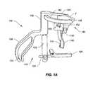
- FIG. 1Ais a side view of an exemplary embodiment of a positioning instrument of the present invention shown in use with a partial bone;
- FIG. 1Bis a perspective view of the positioning instrument of FIG. 1A shown in use with a partial bone;
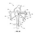
- FIG. 2Ais another perspective view of the positioning instrument of FIG. 1A in situ
- FIG. 2Bis yet another perspective view of the positioning instrument of FIG. 1A in situ;
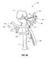
- FIG. 3Ais a perspective view of another exemplary embodiment of a positioning instrument of the present invention in use with a partial bone;
- FIG. 3Bis a top-down view of the positioning instrument of FIG. 3A and partial bone;
- FIG. 4represents pin placement in a partial bone using the positioning instrument of the present invention.
- FIG. 5Ais a perspective view of an exemplary embodiment of a positioning instrument of the present disclosure.
- FIG. 5Bshows the positioning instrument of FIG. 5A in situ
- FIG. 6Ais a perspective front view of another exemplary embodiment of a positioning instrument of the present disclosure in use with a partial bone;
- FIG. 6Bis a perspective rear view of the positioning instrument of FIG. 2A in use with a partial bone
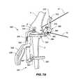
- FIG. 7Ais a perspective view of yet another exemplary embodiment of a positioning instrument of the present disclosure in situ.
- FIG. 7Bis another perspective view of the positioning instrument of FIG. 6A in use with a flexed joint.
- the present disclosureprovides a methodology, devices and instruments for diagnosing and treating joint pain to restore natural joint function and preserving, as much as possible, the joint's articular and cartilage surface.
- Treatments through the joint that violate the articular and cartilage surfaceoften weaken the bone and have unpredictable results.
- the embodimentsdiagnose and treat pain at its source in the subchondral region of a bone of a joint to relieve the pain.
- pain associated with joints, especially osteoarthritic jointscan be correlated to bone defects or changes at the subchondral level rather than, for example, the severity of osteoarthritic progression or defects at the articular surface level.
- bone defectssuch as bone marrow lesions, edema, fissures, fractures, hardened bone, etc. near the joint surface lead to a mechanical disadvantage and abnormal stress distribution in the periarticular bone, which may cause inflammation and generate pain.
- periarticular bonewhich may or may not be sclerotic
- the present disclosureprovides methods, devices, and systems for a subchondral procedure.
- This procedure and its associated devices, instruments, etc.are also marketed under the registered trademark name of SUBCHONDROPLASTYTM.
- SUBCHONDROPLASTYTM procedureis a response to a desire for an alternative to patients facing partial or total knee replacement.
- the SUBCHONDROPLASTYTM or SCPTM techniqueis intended to both strengthen the bone and stimulate the bone.
- SCPTMbone fractures or non-unions are stabilized, integrated or healed, which results in reduction of a bone defect, such as a bone marrow lesion or edema.
- SCPTMrestores or alters the distribution of forces in a joint to thereby relieve pain.
- SCPTMcan be performed arthroscopically or percutaneously to treat pain by stabilizing chronic stress fracture, resolving any chronic bone marrow lesion or edema, and preserving, as much as possible, the articular surfaces of the joint.
- SUBCHONDROPLASTYTMgenerally comprises evaluating a joint, for example, by taking an image of the joint, detecting the presence of one or more subchondral defects, diagnosing which of these subchondral defects is the source of pain, and determining an extent of treatment for the subchondral defect.
- the present techniqueis particularly suited for treating chronic defects or injuries, where the patient's natural healing response has not resolved the defect. It should be noted, however, that the technique is equally applicable to treatment of defects in the subchondral region of bone where the defect is due to an acute injury or from other violations.
- the present disclosureprovides several exemplary treatment modalities for SCPTM for the different extents of treatment needed. Accordingly, a medical practitioner may elect to use the techniques and devices described herein to subchondrally treat any number of bone defects as he deems appropriate.
- detection and identification of the relevant bone marrow lesion or bone marrow edemacan be achieved by imaging, e.g., magnetic resonance imaging (MRI), X-ray, manual palpation, chemical or biological assay, and the like.
- MRImagnetic resonance imaging
- X-rayX-ray
- a T1-weighted MRIcan be used to detect sclerotic bone, for example.
- a T2-weighted MRIcan be used to detect lesions, edemas, and cysts.
- X-ray imagingmay be suitable for early-stage as well as end-stage arthritis. From the imaging, certain defects may be identified as the source of pain.
- defects that are associated with chronic injury and chronic deficit of healingare differentiated from defects that result, e.g., from diminished bone density.
- SCPTM treatmentsare appropriate for a BML or BME that may be characterized as a bone defect that is chronically unable to heal (or remodel) itself, which may cause a non-union of the bone, stress or insufficiency fractures, and perceptible pain.
- Factors consideredmay include, among other things, the nature of the defect, size of the defect, location of the defect, etc. For example, bone defects at the edge near the articular surface or periphery of a joint may be often considered eligible for treatment due to edge-loading effects as well as the likelihood of bone hardening at these locations.
- a bone defect caused by an acute injurywould generally be able to heal itself through the patient's own natural healing process.
- SCPTM treatmentscan be administered on acute stress fractures, BML or BME, or other subchondral defects, as previously mentioned.
- the SCPTM treatmentmay continue after surgery.
- the patientmay be monitored for a change in pain scores, or positive change in function.
- patientsare also checked to see when they are able to perform full weight-bearing activity and when they can return to normal activity.
- the SCPTM procedurecan be completely reversed in the event that a patient requires or desires a joint replacement or other type of procedure.
- the SCPTM treatmentmay also be performed in conjunction with other procedures, such as cartilage resurfacing, regeneration or replacement, if desired.
- the present disclosureprovides a number of treatment modalities, and associated devices, instruments and related methods of use for performing SUBCHONDROPLASTYTM. These treatment modalities may be used alone or in combination.
- the subchondral bone in the region of the bone marrow lesion or defectcan be strengthened by introduction of a hardening material, such as a bone substitute, at the site.
- a hardening materialsuch as a bone substitute
- the bone substitutemay be an injectable calcium phosphate ensconced in an optimized carrier material.
- the injected materialmay also serve as a bone stimulator that reinvigorates the desired acute bone healing activity.
- PMMApolymethylmethacrylate
- CaP cement injectionscan be made at the defect site.
- PMMA injectionmay increase the mechanical strength of the bone, allowing it to withstand greater mechanical stresses.
- CaP cement injectionmay also increase the mechanical strength of the bone, while also stimulating the localized region for bone fracture repair.
- the injectioncan be made parallel to the joint surface.
- the injectioncan be made at an angle to the joint surface.
- the injectioncan be made below a bone marrow lesion.
- the subchondral bone regioncan be stimulated to trigger or improve the body's natural healing process.
- one or more small holesmay be drilled at the region of the defect to increase stimulation (e.g., blood flow, cellular turnover, etc.) and initiate a healing response leading to bone repair.
- an osteogenic, osteoinductive, or osteoconductive agentmay be introduced to the site.
- Bone graft materialfor example, may be used to fill the hole.
- Electrical or heat stimulationmay also be employed to stimulate the healing process of a chronically injured bone.
- Chemical, biochemical and/or biological stimulationmay also be employed in SCPTM. For instance, stimulation of bone tissue in SCPTM may be enhanced via the use of cytokines and other cell signaling agents to trigger osteogenesis, chondrogenesis, and/or angiogenesis to perhaps reverse progression of osteoarthritis.
- an implantable devicemay be implanted into the subchondral bone to provide mechanical support to the damaged or affected bone region, such as where an insufficiency fracture or stress fracture has occurred.
- the implantmay help create a better load distribution in the subchondral region.
- the implantmay support tibio-femoral compressive loads.
- the implantmay mechanically integrate sclerotic bone with the surrounding healthy bone tissue.
- the implantmay be placed in cancellous bone, through sclerotic bone, or under sclerotic bone at the affected bone region.
- the implantmay also be configured as a bi-cortical bone implant.
- one side of the implantcan be anchored to the peripheral cortex to create a cantilever beam support (i.e., a portion of the implant is inserted into bone but the second end stays outside or near the outer surface of the bone).
- the implantmay be inserted using a guide wire.
- the implantmay be inserted over a guide wire.
- the implantmay be delivered through a guide instrument.
- the implantmay further be augmented with a PMMA or CaP cement injection, other biologic agent, or an osteoconductive, osteoinductive and/or osteogenic agent.
- the augmentation materialmay be introduced through the implant, around the implant, and/or apart from the implant but at the affected bone region, such as into the lower region of a bone marrow lesion or below the lesion.
- the implantmay act as a portal to inject the augmentation material into the subchondral bone region.
- the present disclosurealso provides suitable implantable fixation devices for the surgical treatment of these altered bone regions or bone defects, especially at the subchondral level.
- Applicantshave also discovered devices and instruments that can be used in combination with cements or hardening materials commonly used to repair damaged bone by their introduction into or near the site of damage, either to create a binding agent, cellular scaffold or mechanical scaffold for immobilization, regeneration or remodeling of the bone tissue.
- the embodimentsrelate to instruments and associated methods for the surgical treatment of a joint, and particularly to a bone defect at that joint region. More specifically, the embodiments relate to instruments that allow variable angle approaches to the surgical repair and treatment of bone tissue at these joints and associated methods of use. Even more specifically, in one embodiment the instruments and associated methods for use are suitable for the repair of a tibial bone of a knee joint. In another embodiment, the instruments of the present disclosure allow fast, easy, precise and repeatable surgical targeting of a defect in an upper bone of a joint, and even more specifically of a defect in a femur near the contact surface.
- the compressive load between the contact bonesi.e., the femur and the tibia
- the tibio-femoral contact areareduces and starts to get localized at the site of the cartilage defect.
- the localization of the stressesmay also occur due to varus or valgus deformity.
- the conditionmay occur because of osteoporosis, where bone becomes weak and is no longer able to support normal loads. This condition leads to higher localized contact stresses in the cartilage, and the subchondral region below the cartilage.
- osteoarthritic jointscan be correlated to bone defects or changes at the subchondral level.
- bone defectssuch as bone marrow lesions, edema, fissures, fractures, etc. near the joint surface lead to abnormal stress distribution in the periarticular bone, which may or may not cause inflammation and generate pain.
- the makeup of the periarticular bonewhich may or may not be sclerotic
- treatment of the bone in an effort to alter the structural makeup of the affected periarticular boneleads to reduced inflammation and pain. Over time, normal physiologic stress distribution can be achieved, and mechanical congruity restored, thereby resulting in healing of the inflammation and reduction or elimination of pain.
- the present inventionprovides suitable instruments and associated methods for the surgical treatment of these bone defects, especially at the subchondral level near sclerotic bone.
- FIGS. 1A and 1Bshow an exemplary embodiment of a positioning instrument 100 of the present disclosure.
- the positioning instrument 100enables repeatable, controlled delivery of a device to a target area 6 in the bone 2 .
- the devicemay be a pin 10 .
- the term “device”is used herein to refer generally to any number of implantable devices, materials (such as bone substitute materials) and instruments suitable for bone treatment and/or repair.
- the devicemay be an implantable device, an insertion tool, a drill bit, an injection needle, a catheter, or any other surgical instrument. Exemplary implantable devices are disclosed in co-pending and co-owned U.S. patent application Ser. No. 12/950,306, filed Nov.
- the positioning instrument 100may be used to provide quick, easy, accurate and repeatable targeting of a specific bone defect for a number of instruments or implants that can perform any variety of treatment functions.
- the positioning instrument 100is configured to provide simple, repeatable targeting of a local target area 6 at or near a bone defect in a bone of a joint for percutaneous treatment of the defect.
- the positioning instrument 100allows targeting of a target area 6 from various angles, or locations, outside the bone 2 .
- the bonemay be a tibia 2 of a knee joint, for example.
- the bonemay be any other kind of joint bone.
- the positioning instrument 100may comprise a main body 102 from which an indicator probe 104 extends.
- the probe 104may extend at an angle to a transverse plane of the bone. The angle could be in the range of about 1 to 15 degrees, more preferably about 2 to 10 degrees, and even more preferably about 3 to 7 degrees.
- the probe 104may be configured to extend at an angle of about 7 degrees to a transverse plane of the tibial plateau.
- the probe 104This slight angle enables the probe 104 to be oriented parallel to the tibial plateau (which has this inherent slope), thereby allowing the user to have instrumentation that better matches the natural contours of the bone to be treated and which allows for the correct angular access to the target site. Accordingly, the angular orientation of the probe 104 allows the user a greater angular opening to access the bone clear of ligament and other surrounding soft tissue, and prevents inadvertent angular insertion of any instruments or devices through cartilage or other unintended bone or soft tissue, causing damage to the joint.
- the indicator probe 104may include on its underside at the terminal end a knob 106 for placement against a bone surface. At an opposite end the main body 102 extends into a handle 108 .
- the handle 108may be configured with a cutout portion 110 for gripping the instrument 100 .
- Tool-receiving holes 112may be provided on the main body 102 , as shown in FIGS. 2A and 2B , for receiving a tool such as a pin 10 to further secure the positioning instrument 100 against the bone 2 .
- a stabilizer component 120may optionally be provided for use with the positioning instrument 100 .
- the stabilizer component 120may be detachable, and include a shaft 122 that can be quickly and easily attached or removed from the main body 102 of the positioning instrument 100 . It is contemplated that the shaft 122 may be configured to be adjustable in length relative to the main body 102 to accommodate different sized patients.
- a stem 124may extend from the shaft 122 , as shown in FIG. 1A .
- the stem 124may be configured to be angularly adjustable relative to the shaft 122 , for example.
- Attached to the stem 124is a brace 126 .
- the brace 126may be hinged to the leg stem to allow the brace to pivot as needed.
- the brace 126may be positioned against the patient's leg during use.
- FIGS. 3A and 3Bshow an embodiment of the positioning instrument 100 without the optional stabilizer component 120 .
- the positioning instrument 100may also include a rail system 140 comprising a first rail arm 142 and a second rail arm 144 , as shown in FIGS. 2A and 2B .
- Each of the rail arms 142 , 144may be configured to be detachable from the main body 102 of the positioning instrument 100 . Accordingly, the positioning instrument 100 may be used with either one or both of the rail arms 142 , 144 .
- each of the rail arms 142 , 144may be provided with an open slot 146 for receiving any one of a variety of alignment guides, such as a primary alignment guide 150 shown.
- primary alignment guide 150may include a tab or other protrusion that would enable the guide 150 to attach to and slide along the first rail arm 142 within its open slot 146 . This type of arrangement also allows the first rail arm 142 to be quickly and easily detached (i.e., slipped off) the guide 150 after the guide 150 has been independently secured to the bone 2 .
- each of the rail arms 142 , 144is shown to be circular, it is contemplated that the rail arms 142 , 144 may be provided with any other geometric configuration such as an L-shape, U-shape, C-shape, etc. so long as it is capable of supporting and positioning the primary alignment guide 150 adjacent to the bone to be treated.
- Primary alignment guide 150may serve as a jig, or a platform/frame to guide a device to a specific location on the bone 2 being treated.
- One or more device portals 152may be provided on the primary alignment guide 150 .
- Each portal 152has a predetermined distance and spatial relationship relative to the other portals, such that the clinician can determine with accuracy the depth of the portal 152 relative to the indicator probe 104 and consequently the top surface of the bone 2 .
- the portals 152serve as spatial reference or orientation or location markers for the clinician.
- the device portals 152are configured to provide accurate and controlled delivery of a device to the target site.
- the portals 152may be configured at any desired angle relative to the alignment guide 150 .
- the portals 152may be angularly configured to guide, or direct, the device in a parallel direction relative to the top of the bone being treated.
- the portals 152may be angularly configured to direct the device in a perpendicular direction relative to the top of the bone, for example.
- the positioning instrument 100may be particularly suited to enable implants or other instruments to be inserted in a predetermined angular orientation to the top bone surface in an easy, fast and precise manner.
- pins 10may be placed through tool-receiving openings 154 provided on the primary alignment guide 150 to secure the guide 150 to the bone 2 .
- the tool-receiving opening 154may also receive an insertion tool for the delivery of an implantable device or injectable material (such as a bone substitute material), and the device portal 152 may also receive a pin 10 , if so desired. Accordingly, the surgeon may use the device portal 152 and the tool-receiving hole 154 interchangeably as needed.
- an implantable device or injectable materialsuch as a bone substitute material
- a detachable inferior guide portion 160may optionally be provided with the positioning instrument 100 .
- the inferior guide portion 160may include one or more tool-receiving holes 162 for receiving a tool.
- the toolmay be, for example, a pin, needle or drill bit.
- the toolmay be a drill to drill a hole in the bone 2 , for example.
- the toolmay be a device insertion tool for introduction of an implantable device, for example.
- the inferior guide portion 160offers a distal, or inferior approach guide, for targeting the lower area of the target site or other tissue area from different angular approaches through tool-receiving holes 162 . It is contemplated that any known mechanism for attaching the inferior guide portion 160 to the primary alignment guide 150 may be provided, so long as the mechanism allows quick and easy detachment, without disturbing any other components of the instrument 100 or tools that may have been employed during its use.
- the second rail arm 144may be seen.
- the jointis a knee joint and the upper bone is the femur 4 , the lower bone being the tibia 2 .
- the defect to be targetedis located in the tibia 2 near the contact surface.
- the second rail arm 144may be offset with respect to the first rail arm 142 by a distance d. Accordingly, the second rail arm 144 may have a larger radius than first rail arm 142 .
- the second rail arm 144also includes an open slot 146 for receiving an alignment guide. This type of arrangement allows the second rail arm 144 to be quickly and easily removed from the alignment guide after the guide has been independently secured to the bone.
- the second rail arm 144may be configured to receive a transverse alignment guide 170 .
- the transverse alignment guide 170may include a tab or other protrusion (not shown) to allow it to connect to and slide along the second rail arm 144 . Further, similar to inferior guide portion 160 , the transverse alignment guide 170 may include one or more tool-receiving holes 172 for receiving a tool.
- the toolmay be, for example, a pin, needle or drill bit. In one instance, the tool may be a drill to drill a hole in the bone 2 , for example. In another instance, the tool may be a device insertion tool for introduction of an implantable device, for example.
- the transverse alignment guide 170offers a distal, or inferior approach guide, for targeting the lower area of the target site or other tissue area from a different angle, or location, with respect to the insertion site.
- the approachis from a transverse angle.
- the primary target areais the medial side of the knee
- the transverse guide 170would target the approach from the opposite or contralateral side of the same bone.
- the positioning instrument 100 of the present disclosureprovides several advantages, including simple, repeatable targeting of a defect in a bone for percutaneous treatment of that defect.
- the indicator probe 104can be used arthroscopically to locate the defect visually from above the cartilage surface.
- the circular rail system 140serves as a frame for a 3-dimensional reference system to locate the defect, while the various alignment guides and the corresponding device or tool-receiving holes allow for percutaneous targeting of the defect.
- reference from the probe 104 to the primary alignment guide 150allows for repeatable targeting of the defect in the range of about 5-10 mm below the articular surface where the indicator probe 104 resides.
- the positioning instrument 100 of the present disclosureis suitable for use where it is desirable to treat a local area specific to a defect being identified using a percutaneous approach near the defect.
- the positioning instrument 100 shown in FIGS. 1A and 2B with only the first rail arm 142 attachedcan be used to target a target area 6 local to a defect in a bone 2 for repair.
- the indicator probe 104is used to locate the local area specific to the defect, or the target area 6 , in the cartilage above the defect.
- the defectcould be, for example, a bone marrow lesion in the subchondral region of the bone to be treated.
- the primary alignment guide 150is then positioned along the circular rail system 140 , specifically the first rail arm 142 , to the desired location for a percutaneous approach to the target area 6 .
- Pins 10can be used to fix the primary alignment guide 150 to the bone 2 and the circular rail system 120 can be removed. Pins 10 can be inserted through the primary alignment guide 150 and into the target area 6 . In addition, pins 10 can be inserted into the target area 6 from an inferior approach using the inferior guide portion 160 . Once the pins 10 are fixed in the targeted positions, the primary alignment guide 150 and the inferior guide portion 160 can be removed, leaving only the pins 10 behind.
- the target area 6 local to the defectcan be strengthened by introduction of a hardening material at the site.
- a hardening materialfor example, polymethylmethacrylate (PMMA) or calcium phosphate (CaP) cement injections can be made at the defect site.
- PMMA injectionmay increase the mechanical strength of the bone, allowing it to withstand greater mechanical stresses.
- CaP cement injectionmay also increase the mechanical strength of the bone, while also stimulating the localized region for bone fracture repair.
- the injectioncan be made parallel to the joint surface.
- the injectioncan be made at an angle to the joint surface.
- the injectioncan be made below the target area 6 .
- the target area 6can be stimulated to improve the body's natural healing process.
- small holesmay be drilled at the region of the defect to increase stimulation (e.g., blood flow, cellular turnover, etc.) and initial bone repair.
- an osteogenic, osteoinductive, or osteoconductive agentmay be introduced to the site. Bone graft material, for example, may be used to fill the hole. This treatment modality may create a better load supporting environment leading to long term healing.
- an implantable devicemay be implanted into target area 6 to provide mechanical support to the damaged or affected bone region, such as where an insufficiency fracture has occurred.
- the implantmay help create a better load distribution in the subchondral region.
- the implantmay support tibio-femoral compressive loads.
- the implantmay mechanically integrate sclerotic bone with the surrounding healthy bone tissue.
- each of the above-mentioned treatment modalitiesmay be administered independent of one another, it is contemplated that any combination of these modalities may be applied together and in any order so desired, depending on the severity or stage of development of the bone defect(s).
- the positioning instrument 100 of FIGS. 2A , 2 B, 3 A and 3 B with both the first and second rail arms 142 , 144 attachedcan be used to target a target area 6 from multiple angles, or locations.
- the surgeonmay identify the defect using MRI or other imaging technology. Once identified, either arthroscopically or through imaging technology, the surgeon can secure the positioning instrument 100 in place by securing pins 10 through the tool-receiving holes of the main body 102 and/or the alignment guide 150 .
- the brace 126may be positioned against a portion of the patient's lower leg, in the case of a knee joint.
- the surgeonmay elect to insert a drill bit through one of the device portals 152 and drill a hole or cavity proximate to the defect.
- the surgeonmay decide that drilling a cavity is sufficient treatment and after the cavity is created, the drill bit can be removed and the procedure complete.
- the surgeonmay elect to repeat these steps using the tool-receiving holes of either or both the inferior guide portion 160 and transverse alignment guide 170 to access and target the defect from various angles and locations.
- the transverse alignment guide 170may be positioned along the second rail arm 144 to the desired location for a transverse approach to the target area 6 .
- Pins 10can be used to fix the transverse alignment guide 170 to the bone 2 before removing the second rail arm 144 .
- the proper positioning of the pins 10can be similar to that shown in FIG. 4 .
- any of the pins 10may be substituted for K-wires so that additional instruments and tools may be applied through the tool-receiving holes 162 , 172 . Subsequently, the treatment modalities mentioned earlier can be employed. Alternatively, it is contemplated that the inferior guide portion 160 and the transverse alignment guide 170 may be utilized to assist with the drilling of cavities into the bone through their respective tool-engaging holes 162 , 172 . If the surgeon elects to perform additional treatment steps, he could insert an injectable material and/or an implantable device into the pre-drilled cavities.
- a contralateral, or transverse approach to the target area 6allows for a more direct, normal angular approach of any kind of implantable device into the bone 2 instead of a shallow angular approach that can happen when directing an implantable device from an inferior or distal approach into the target area 6 on the same side.
- Another benefit of a transverse approach to the target area 6is the avoidance of weakening the bone on the same side of the defect for defects that reside near the periphery of the bone. For example, by avoiding approaching the defect from an inferior angle to the same side near the periphery, the user avoids possible breakage of the bone from a shallow angle approach.
- the transverse approachallows the user to span across a greater area of bone, there is more opportunity to adjust the depth of any drill or insertion near the target area 6 .
- Thisoffers less risk compared to a smaller bone depth on the same side of the bone with an inferior approach.
- the ability to approach the defect or target site through a greater area of bonealso provides the opportunity to compact more bone tissue at the target site.
- the process of compacting bone tissue at the target sitemay be a treatment modality by itself. Since the positioning instrument 100 of the present disclosure provides the advantage of precise and repeated access to a target site from a variety of angles, the positioning instrument 100 may be used to compact bone tissue at the target site from multiple approaches, or angles, creating a starburst-like pattern.
- FIGS. 5A and 5Bshow another exemplary embodiment of a positioning instrument 220 of the present disclosure.
- the positioning instrument 220enables repeatable, controlled delivery of a device to a target area in the bone.
- the devicemay be a pin 10 .
- the term “device”is used herein to refer generally to any number of implantable devices, materials and instruments suitable for bone treatment and/or repair.
- the devicemay be an implantable device, an insertion tool, a drill bit, an injection needle, a catheter, or any other surgical instrument.
- the positioning instrument 220may be used to provide quick, easy, accurate and repeatable targeting of a specific bone defect for a number of instruments or implants that can perform any variety of treatment functions.
- the positioning instrument 220may comprise a main body 222 from which a support arm 224 extends in a generally perpendicular angle from one end of the main body 222 .
- the support arm 224terminates into an indicator probe, contoured seat, or rest, 226 that is suited for placement against a condyle of a femur 4 , as shown in FIG. 5B .
- the support arm 224could serve as an indicator probe to be used as a visual pointer to indicate a possible visible area of a defect on the condyle of the femur 4 .
- a handle 228may also extend generally perpendicular to the body 222 .
- Tool-receiving holes 232may be provided on the main body 222 for receiving a tool such as a pin, wire, or needle, for example.
- the toolmay be one that is suitable to secure the main body 222 to the femur 4 .
- the toolmay also easily be an insertion tool for the delivery of an implantable device or injectable material to the femur 4 , if so desired.
- the stabilizer component 240may be detachable, and include a shaft 242 that can be quickly and easily attached or removed from the main body 222 . It is contemplated that the shaft 242 may be configured to be adjustable in length relative to the main body 222 to accommodate different sized patients.
- the shaft 242can receive a stem 244 that is configured to be angularly adjustable relative to the shaft 242 . Attached to the stem 244 is a brace 246 configured for placement against a bone surface, such as the patient's leg, as shown in FIG. 5B .
- the brace 246may be hinged to the stem 244 to allow the brace 246 to pivot as needed.
- the positioning instrument 220may also include a rail 250 extending from the main body 222 of the instrument 220 .
- the rail 250may be circular, as shown, or any other geometric configuration such as an L-shape, U-shape, C-shape, etc.
- the rail 250may be configured to receive an alignment guide 260 .
- the alignment guide 260may serve as a jig, or a platform/frame to guide any kind of instrument, tool or device to a specific location on the bone 4 being treated.
- the alignment guide 260may be configured to be detachable from the rail 250 during use.
- One or more device portals 262may be provided on the alignment guide 260 .
- Each portal 262has a predetermined distance and spatial relationship relative to the other portals, such that the clinician can determine with accuracy the depth of the portal 262 relative to the rail 250 and consequently the bone surface of the bone 4 being treated.
- the portals 262serve as spatial references or orientation or location markers for the clinician.
- the device portals 262are configured to allow repeated, accurate and controlled delivery of a device to the target site.
- the alignment guide 260may additionally include tool-receiving holes 264 for receiving a tool such as a pin, wire, or needle, for example.
- the toolmay be one that is suitable to secure the guide 260 to the femur 4 .
- the toolmay also easily be an insertion tool for the delivery of an implantable device or injectable material to the femur 4 , if so desired. Accordingly, the surgeon may use the device portal 262 and the tool-receiving hole 264 interchangeably as needed.
- the positioning instrument 220can be placed such that the contoured seat 226 rests against a bone surface of the femur 4 , as shown in FIG. 5B .
- the optional stabilizer component 240may be used to stabilize the positioning instrument 220 against the patient's leg during surgery.
- One or more pins 10such as the one shown, may be used to secure one or more portions of the positioning instrument 220 to the femur 4 , such as by placement through the tool-receiving holes 232 , 264 of the main body 222 or alignment guide 260 .
- the surgeonmay elect to insert a device through one of the device portals 262 of the alignment guide to a target site on the femur 4 .
- the surgeonmay repeat the procedure again, or multiple times, using the same device portal 262 .
- the surgeonmay perform another procedure by placing a device through another device portal 262 on the alignment guide 260 .
- the positioning instrument 220 of the present disclosureallows repeated, accurate, precise and easy targeting of an area to be treated on the femur 4 .
- the positioning instrument 220is especially helpful in providing the surgeon with the ability to repeatedly and accurately target an area of the femur 4 near the bone surface from the side, where space is limited and the ability to navigate the patient's natural anatomy at this region provides challenges to the treatment of a defect close to the bone surface.
- FIGS. 6A and 6Billustrate another exemplary embodiment of a positioning instrument 320 of the present disclosure.
- the positioning instrument 320is similar to positioning instrument 220 .
- positioning instrument 320may comprise a main body 322 , a support arm 324 that extends in a generally perpendicular angle from one end of the main body 322 , and a handle 328 also extending generally perpendicular to the body 322 from an opposite end.
- the support arm 324may terminate in a bumper 334 that can be configured to provide a cushion against a bone surface.
- the bumper 334may also be configured as, for example, a rounded knob, suction cup or plunger for placement against a bone.
- the bumper 334may serve as an indicator probe to be used as a visual pointer to indicate a possible visible area of a defect on the condyle of the femur 4 (not shown). Although the femur 4 is not shown in FIGS. 6A and 6B , it is understood that the bumper 334 may rest against the condyle of the femur 4 as shown in FIGS. 7A and 7B .
- the main body 322 of positioning instrument 320may also be provide with tool-receiving holes 332 for receiving a tool such as a pin, wire, or needle, for example, to secure the positioning instrument 320 to the bone.
- the positioning instrument 320may be secured to the lower leg.
- the handle 328may include a cutout portion 336 for ease of gripping the instrument 320 .
- the stabilizer component 340may be provided with the positioning instrument 320 .
- the stabilizer component 340may be detachable, and include a shaft 342 that can be quickly and easily attached or removed from the main body 322 of the positioning instrument 320 .
- the shaft 342may be configured to be adjustable in length relative to the main body 322 to accommodate different sized patients.
- the shaft 342can receive a stem 344 that is configured to be angularly adjustable relative to the shaft 342 .
- Attached to the stem 344is a brace 346 configured for placement against a body surface, such as the patient's leg. Though not shown in FIGS. 6A and 6B , the brace 346 may be configured to rest against the patient's lower leg.
- the brace 346may be hinged to the stem 344 to allow the brace 346 to adjustably pivot as needed.
- the positioning instrument 320may also include a rail 350 extending from the main body 322 of the instrument 320 .
- the rail 350may be circular, as shown, or any other geometric configuration such as an L-shape, U-shape, C-shape, etc.
- the rail 350may be configured to receive an alignment guide 360 on its upper surface, as shown in FIGS. 6A and 6B .
- the rail 350may be provided with an open slot 352 for receiving a protrusion or other extension (not shown) on the alignment guide 360 .
- the alignment guide 360may be slidable and detachable from this open slot 352 of the rail 350 .
- the alignment guide 360may contain one or more device portals 362 , with each portal 362 having a predetermined distance and spatial relationship relative to the other portals, such that the clinician can determine with accuracy the depth of the portal 362 relative to the rail 350 and consequently the bone surface of the bone to be treated.
- the alignment guide 360may additionally include tool-receiving holes 364 for receiving a tool such as a pin, wire, or needle, for example.
- the toolmay be one that is suitable to secure the guide 360 to the upper bone of the joint. However, the tool may also easily be an insertion tool for the delivery of an implantable device or injectable material to the upper bone, if so desired. Accordingly, the surgeon may use the device portal 362 and the tool-receiving hole 364 interchangeably as needed.
- a detachable superior guide component 370may optionally be provided with the positioning instrument 320 , as shown in FIGS. 6A and 6B .
- the superior guide component 370may include one or more tool-receiving holes 372 for receiving a tool.
- the toolmay be, for example, a pin, needle or drill bit.
- the toolmay be a drill to drill a hole in the femur 4 (not shown), for example.
- the toolmay be a device insertion tool for introduction of an implantable device, for example.
- the superior guide component 370offers a proximal, or superior approach guide, for targeting the upper area of the target site or other tissue area from different angular approaches through tool-receiving holes 372 . It is contemplated that any known mechanism for attaching the superior guide component 370 to the alignment guide 350 may be provided, so long as the mechanism allows quick and easy detachment, without disturbing any other components of the instrument 320 or tools that may have been employed during its use.
- this positioning instrument 320allows the surgeon to locate, access and target a defect area on the upper bone of a joint while bracing against the lower portion of the joint.
- the alignment guide 360resides above the rail 350 , allowing the surgeon to position the alignment guide 360 along the rail 350 and relative to the top bone of a joint, for predetermined angular orientation of the instruments, tools or devices to the target area on the upper bone.
- the ability to brace against the lower limb while targeting the femurprovides the surgeon with the advantage of having less pins and extended hardware in the upper area, which would limit visual access as well as surgical access to the femur.
- An additional advantageis that the surgeon can pivot the lower limb to a certain angle to position the instrument 320 at a certain location on the upper limb, using the stability of the brace 346 against the lower limb while treating the upper limb.
- FIGS. 7A and 7Billustrate yet another exemplary embodiment of a positioning instrument 420 of the present disclosure.
- Positioning instrument 420may comprise a main body 322 , a support arm 324 that extends in a generally perpendicular angle from one end of the main body 322 , and a handle 328 also extending generally perpendicular to the body 322 from an opposite end.
- the support arm 324may terminate in a bumper 334 that can be configured to provide a cushion against a bone surface, such as the contact surface 6 of the femur 4 , as shown in FIGS. 6A and 6B .
- the bumper 334may also be configured as, for example, a rounded knob, suction cup or plunger for placement against a bone.
- the main body 322 of positioning instrument 420may also be provide with tool-receiving holes 332 for receiving a tool such as a pin, wire, or needle, for example, to secure the positioning instrument 420 to the lower portion of the joint.
- a toolsuch as a pin, wire, or needle
- the positioning instrument 420may be secured to the patient's lower leg using pins through the tool-receiving holes 332 , if desired.
- the handle 328may include a cutout portion 336 for ease of gripping the instrument 420 .
- an optional stabilizer component 340may be provided with the positioning instrument 420 .
- the stabilizer component 340may be detachable, and include a shaft 342 that can be quickly and easily attached or removed from the main body 322 of the positioning instrument 420 .
- the shaft 342may be configured to be adjustable in length relative to the main body 322 to accommodate different sized patients.
- the shaft 342can receive a stem 344 that is configured to be angularly adjustable relative to the shaft 342 .
- Attached to the stem 344is a brace 346 configured for placement against a body surface, such as the patient's leg. As shown, the brace 346 may be configured to rest against the patient's lower leg.
- the brace 346may be hinged to the stem 344 to allow the brace 346 to adjustably pivot as needed.
- the positioning instrument 420may also include a rail 350 extending from the main body 322 of the instrument 420 .
- the rail 350may be circular, as shown, or any other geometric configuration such as an L-shape, U-shape, C-shape, etc.
- the rail 350may be configured to receive an alignment guide 360 on its upper surface.
- the alignment guide 360 of instrument 420may be attached to the rail 350 at a hinged connection 354 that would enable the alignment guide 360 to pivot relative to the rail 350 , as shown in FIGS. 7A and 7B .
- the alignment guide 360may contain one or more device portals 362 , with each portal 362 having a predetermined distance and spatial relationship relative to the other portals, such that the clinician can determine with accuracy the depth of the portal 362 relative to the rail 350 and consequently the bone surface of the bone to be treated.
- the alignment guide 360may additionally include tool-receiving holes 364 for receiving a tool such as a pin, wire, or needle, for example.
- the toolmay be one that is suitable to secure the guide 360 to the upper bone of the joint. However, the tool may also easily be an insertion tool for the delivery of an implantable device or injectable material to the upper bone, if so desired. Accordingly, the surgeon may use the device portal 362 and the tool-receiving hole 364 interchangeably as needed.
- a detachable superior guide component 370may optionally be provided with the positioning instrument 420 .
- the superior guide component 370may include one or more tool-receiving holes 372 for receiving a tool.
- the toolmay be, for example, a pin, needle or drill bit.
- the toolmay be a drill to drill a hole in the femur 4 , for example.
- the toolmay be a device insertion tool for introduction of an implantable device, for example.
- the superior guide component 370offers a proximal, or superior approach guide, for targeting the upper area of the target site or other tissue area from different angular approaches through tool-receiving holes 372 . It is contemplated that any known mechanism for attaching the superior guide component 370 to the alignment guide 360 may be provided, so long as the mechanism allows quick and easy detachment, without disturbing any other components of the instrument 420 or tools that may have been employed during its use.
- this positioning instrument 420allows the surgeon to locate, access and target a defect area on the upper bone of a joint while bracing against the lower portion of the joint.
- the ability to brace against the lower leg while targeting the femur 4provides the surgeon with the advantage of having less pins and extended hardware in the upper area, which would limit visual access as well as surgical access to the femur. By bracing below the femur, the surgeon can free up more working space around the femur.
- the alignment guide 360 of instrument 420is able to pivot, it is possible to flex the joint (see FIG. 7B ) and still maintain the ability to repeatedly, accurately, easily and precisely locate a target site on the upper bone (femur 4 ) of the joint. In other words, the alignment guide 360 is able to move along with the upper bone of the joint.
- the upper bonemay be a femur for a knee joint repair. It is understood, however, that the positioning instruments of the present disclosure may be applied to an upper bone found in any body joint, such as a hip, ankle or shoulder, etc.
- the surgeonmay identify the defect using MRI or other imaging technology. Once identified, either arthroscopically or through imaging technology, the surgeon can secure the positioning instrument 220 , 320 , 420 in place by securing pins 10 through the tool-receiving holes of the main body and/or the alignment guide.
- the bracemay be positioned against a portion of the upper part or lower part of a patient's lower limb, or leg, in the case of a knee joint.
- the surgeonmay elect to insert a drill bit through one of the device portals and drill a hole or cavity proximate to the defect.
- the surgeonmay decide that drilling a cavity is sufficient treatment and after the cavity is created, the drill bit can be removed and the procedure complete.
- the surgeonmay elect to compact bone tissue at the target site as a treatment modality.
- the surgeoncan approach the target site from a number of different locations (i.e., device portals) or angles (i.e., by adjusting the alignment guide), creating a geometric pattern around the defect, such as a starburst, for example.
- the surgeonmay elect to insert an implantable device through the same device portal into the cavity. This would be accomplished by introducing an insertion tool with the implantable device attached through the alignment guide in a similar manner above. Alternatively, or in addition, the surgeon may insert an injectable material through the device portal and into the cavity or inside, above, below, beside, or around the implantable device. The surgeon may elect to repeat these steps using the tool-receiving holes and the superior guide component 370 to access and target the defect from various angles and locations. The entire method could be employed in a percutaneous fashion if so desired.
Landscapes
- Health & Medical Sciences (AREA)
- Life Sciences & Earth Sciences (AREA)
- Surgery (AREA)
- Orthopedic Medicine & Surgery (AREA)
- Veterinary Medicine (AREA)
- General Health & Medical Sciences (AREA)
- Public Health (AREA)
- Engineering & Computer Science (AREA)
- Biomedical Technology (AREA)
- Heart & Thoracic Surgery (AREA)
- Animal Behavior & Ethology (AREA)
- Molecular Biology (AREA)
- Medical Informatics (AREA)
- Nuclear Medicine, Radiotherapy & Molecular Imaging (AREA)
- Oral & Maxillofacial Surgery (AREA)
- Dentistry (AREA)
- Transplantation (AREA)
- Physical Education & Sports Medicine (AREA)
- Cardiology (AREA)
- Vascular Medicine (AREA)
- Surgical Instruments (AREA)
- Prostheses (AREA)
Abstract
Description
Claims (42)
Priority Applications (10)
| Application Number | Priority Date | Filing Date | Title |
|---|---|---|---|
| HK13104598.3AHK1177128B (en) | 2009-11-20 | 2010-11-19 | Instruments for a variable angle approach to a joint |
| AU2010321822AAU2010321822A1 (en) | 2009-11-20 | 2010-11-19 | Instruments for a variable angle approach to a joint |
| PCT/US2010/057483WO2011063267A1 (en) | 2009-11-20 | 2010-11-19 | Instruments for a variable angle approach to a joint |
| US12/950,355US8951261B2 (en) | 2009-11-20 | 2010-11-19 | Subchondral treatment of joint pain |
| JP2012540101AJP2013511356A (en) | 2009-11-20 | 2010-11-19 | Device for variable angle approach to joints |
| KR1020127015879AKR20120101079A (en) | 2009-11-20 | 2010-11-19 | Instruments for a variable angle approach to a joint |
| US12/950,154US8906032B2 (en) | 2009-11-20 | 2010-11-19 | Instruments for a variable angle approach to a joint |
| EP10832285.0AEP2501306B1 (en) | 2009-11-20 | 2010-11-19 | Instruments for a variable angle approach to a joint |
| CN201080052569.2ACN102740784B (en) | 2009-11-20 | 2010-11-19 | Instruments for variable angle access to joints |
| US14/617,058US9717544B2 (en) | 2009-11-20 | 2015-02-09 | Subchondral treatment of joint pain |
Applications Claiming Priority (5)
| Application Number | Priority Date | Filing Date | Title |
|---|---|---|---|
| US26317009P | 2009-11-20 | 2009-11-20 | |
| US31089710P | 2010-03-05 | 2010-03-05 | |
| US31115210P | 2010-03-05 | 2010-03-05 | |
| US12/950,355US8951261B2 (en) | 2009-11-20 | 2010-11-19 | Subchondral treatment of joint pain |
| US12/950,154US8906032B2 (en) | 2009-11-20 | 2010-11-19 | Instruments for a variable angle approach to a joint |
Publications (2)
| Publication Number | Publication Date |
|---|---|
| US20110125159A1 US20110125159A1 (en) | 2011-05-26 |
| US8906032B2true US8906032B2 (en) | 2014-12-09 |
Family
ID=44060038
Family Applications (1)
| Application Number | Title | Priority Date | Filing Date |
|---|---|---|---|
| US12/950,154Active2031-11-19US8906032B2 (en) | 2009-11-20 | 2010-11-19 | Instruments for a variable angle approach to a joint |
Country Status (7)
| Country | Link |
|---|---|
| US (1) | US8906032B2 (en) |
| EP (1) | EP2501306B1 (en) |
| JP (1) | JP2013511356A (en) |
| KR (1) | KR20120101079A (en) |
| CN (1) | CN102740784B (en) |
| AU (1) | AU2010321822A1 (en) |
| WO (1) | WO2011063267A1 (en) |
Cited By (14)
| Publication number | Priority date | Publication date | Assignee | Title |
|---|---|---|---|---|
| US20110125160A1 (en)* | 2009-11-20 | 2011-05-26 | Knee Creations, Llc | Instruments for targeting a joint defect |
| US9033987B2 (en) | 2009-11-20 | 2015-05-19 | Zimmer Knee Creations, Inc. | Navigation and positioning instruments for joint repair |
| US9119721B2 (en) | 2009-11-20 | 2015-09-01 | Zimmer Knee Creations, Inc. | Method for treating joint pain and associated instruments |
| US9271835B2 (en) | 2009-11-20 | 2016-03-01 | Zimmer Knee Creations, Inc. | Implantable devices for subchondral treatment of joint pain |
| US9351746B2 (en) | 2009-11-20 | 2016-05-31 | Zimmer Knee Creations, Inc. | Coordinate mapping system for joint treatment |
| US9439765B2 (en) | 2009-11-20 | 2016-09-13 | Zimmer Knee Creations, Inc. | Method for subchondral treatment of joint pain using implantable devices |
| US9717544B2 (en) | 2009-11-20 | 2017-08-01 | Zimmer Knee Creations, Inc. | Subchondral treatment of joint pain |
| US9925010B2 (en) | 2016-02-19 | 2018-03-27 | Rajiv D. Pandya | System and technique for accessing extra articular lesions or abnormalities or intra osseous lesions or bone marrow lesions |
| US10064632B2 (en) | 2016-02-19 | 2018-09-04 | Rajiv D. Pandya | System and technique for accessing extra articular lesions or abnormalities or intra osseous lesions or bone marrow lesions |
| US10869679B2 (en) | 2016-02-19 | 2020-12-22 | Sunnybrook Research Institute | Positioning and alignment instrument for introducing surgical devices into bone |
| US11376079B2 (en) | 2016-02-19 | 2022-07-05 | Rajiv D. Pandya | System and technique for accessing extra articular lesions or abnormalities or intra osseous lesions or bone marrow lesions |
| US11419684B2 (en) | 2016-02-19 | 2022-08-23 | Rajiv D. Pandya | System and technique for accessing extra articular lesions or abnormalities or intra osseous lesions or bone marrow lesions |
| US11439412B2 (en) | 2017-08-04 | 2022-09-13 | Wright Medical Technology, Inc. | Screw targeting guide system and method |
| US11963688B2 (en) | 2021-11-20 | 2024-04-23 | Panorthopaedics, Inc. | Device adapted for lateral engagement of an elongated member |
Families Citing this family (27)
| Publication number | Priority date | Publication date | Assignee | Title |
|---|---|---|---|---|
| JP2013511356A (en) | 2009-11-20 | 2013-04-04 | ニー・クリエイションズ・リミテッド・ライアビリティ・カンパニー | Device for variable angle approach to joints |
| US8652148B2 (en)* | 2010-02-25 | 2014-02-18 | Zimmer, Inc. | Tracked cartilage repair system |
| EP2765925A1 (en)* | 2011-10-11 | 2014-08-20 | Zimmer Knee Creations, Inc. | Methods and instruments for subchondral treatment of osteoarthritis in a small joint |
| WO2014053913A2 (en) | 2012-09-07 | 2014-04-10 | Zimmer Knee Creations, Inc. | Navigation instruments for subchondral bone treatment |
| WO2014045124A2 (en) | 2012-09-07 | 2014-03-27 | Zimmer Knee Creations, Inc. | Instruments for controlled delivery of injectable materials into bone |
| US20140074103A1 (en) | 2012-09-07 | 2014-03-13 | Zimmer Gmbh, Inc. | Subchondral treatment of bone defects with bone-derived implant |
| CN103169529B (en)* | 2013-02-04 | 2015-08-05 | 上虞市中医院 | A kind of fracture of the lesser trochanter fixing reductor |
| WO2014179802A2 (en)* | 2013-05-03 | 2014-11-06 | The Curators Of The University Of Missouri | Systems and methods for alignment and site preparation of rotator cuff grafts |
| US9895519B2 (en) | 2013-10-07 | 2018-02-20 | Regentis Biomaterials Ltd. | Treatment of cavities in a human body |
| US9872705B2 (en) | 2013-10-07 | 2018-01-23 | Regentis Biomaterials Ltd. | Treatment of cavities in a human body |
| US10010333B2 (en) | 2014-09-30 | 2018-07-03 | Medos International Sàrl | Side-loading carriage for use in surgical guide |
| US10098646B2 (en) | 2014-09-30 | 2018-10-16 | Medos International Sàrl | Surgical guide for use in ligament repair procedures |
| US10307173B2 (en) | 2014-09-30 | 2019-06-04 | Medos International Sàrl | Gage for limiting distal travel of drill pin |
| US10045789B2 (en) | 2014-09-30 | 2018-08-14 | Medos International Sàrl | Universal surgical guide systems and methods |
| EP3223722B1 (en) | 2014-11-24 | 2019-11-06 | Zimmer Knee Creations, Inc. | Navigation instruments for subchondral bone treatment |
| CA3100061A1 (en) | 2015-09-02 | 2017-03-09 | Wright Medical Technology, Inc. | Chevron osteotomy tools and methods |
| US10918412B2 (en)* | 2015-12-18 | 2021-02-16 | Boston Scientific Scimed, Inc. | Surgical guidance devices, methods, and systems |
| CN107080664B (en)* | 2017-04-25 | 2018-11-02 | 罗梅宏 | A kind of device of bone marrow puncture auxiliary bend |
| US10952754B2 (en)* | 2017-05-08 | 2021-03-23 | The Johns Hopkins University | Orthopedic surgical guide for tunnel placement |
| US11980507B2 (en) | 2018-05-02 | 2024-05-14 | Augmedics Ltd. | Registration of a fiducial marker for an augmented reality system |
| CN109394329B (en)* | 2018-12-07 | 2024-03-19 | 昆明医科大学第二附属医院 | Ankle joint fuses puts nail director |
| US11980506B2 (en)* | 2019-07-29 | 2024-05-14 | Augmedics Ltd. | Fiducial marker |
| US11382712B2 (en) | 2019-12-22 | 2022-07-12 | Augmedics Ltd. | Mirroring in image guided surgery |
| US20240050243A1 (en)* | 2020-12-23 | 2024-02-15 | Formae, Inc. | Instruments and methods for preparing patient recipient site and installing medical implant |
| CN113303866B (en)* | 2021-06-04 | 2022-05-10 | 中南大学湘雅医院 | Thighbone near-end kirschner wire drilling location and many needles drilling auxiliary device |
| WO2023021448A1 (en) | 2021-08-18 | 2023-02-23 | Augmedics Ltd. | Augmented-reality surgical system using depth sensing |
| EP4511809A1 (en) | 2022-04-21 | 2025-02-26 | Augmedics Ltd. | Systems and methods for medical image visualization |
Citations (197)
| Publication number | Priority date | Publication date | Assignee | Title |
|---|---|---|---|---|
| US2697433A (en) | 1951-12-04 | 1954-12-21 | Max A Zehnder | Device for accurately positioning and guiding guide wires used in the nailing of thefemoral neck |
| US3913187A (en) | 1973-10-18 | 1975-10-21 | Nifco Inc | Squeeze-action clamp |
| US3988783A (en) | 1976-01-21 | 1976-11-02 | Richards Manufacturing Company, Inc. | Prosthetic collateral ligament |
| US4037592A (en)* | 1976-05-04 | 1977-07-26 | Kronner Richard F | Guide pin locating tool and method |
| US4108165A (en) | 1977-06-20 | 1978-08-22 | Krautkramer-Branson, Incorporated | Transducer probe for pulse-echo ultrasonic exploration |
| US4360012A (en) | 1980-02-19 | 1982-11-23 | National Research Development Corporation | External fixation devices for orthopaedic fractures |
| US4653487A (en) | 1986-01-29 | 1987-03-31 | Maale Gerhard E | Intramedullary rod assembly for cement injection system |
| US4815454A (en) | 1987-11-16 | 1989-03-28 | Dozier Jr John K | Apparatus and method for injecting bone cement |
| US4883048A (en) | 1986-10-03 | 1989-11-28 | Purnell Mark L | Apparatus and method for use in performing a surgical operation |
| US4911153A (en) | 1988-02-04 | 1990-03-27 | Biomet, Inc. | Orthopedic surgical instrument |
| US4920958A (en) | 1986-11-05 | 1990-05-01 | Minnesota Mining And Manufacturing Company | Drill guide assembly |
| US4964861A (en) | 1988-12-22 | 1990-10-23 | John M. Agee | Instrumentation for implanting prosthetic devices |
| US5098383A (en) | 1990-02-08 | 1992-03-24 | Artifax Ltd. | Device for orienting appliances, prostheses, and instrumentation in medical procedures and methods of making same |
| US5163940A (en) | 1991-03-04 | 1992-11-17 | American Cyanamid Company | Surgical drill guide for tibia |
| US5178164A (en) | 1987-11-10 | 1993-01-12 | Allen George S | Method for implanting a fiducial implant into a patient |
| US5247934A (en) | 1991-08-09 | 1993-09-28 | Trustees Of The University Of Pennsylvania | Method and apparatus for diagnosing osteoporosis with MR imaging |
| US5298254A (en) | 1989-09-21 | 1994-03-29 | Osteotech, Inc. | Shaped, swollen demineralized bone and its use in bone repair |
| US5324295A (en) | 1992-04-24 | 1994-06-28 | Shapiro Michael R | Drill guide for surgical pins |
| US5342363A (en) | 1992-11-30 | 1994-08-30 | Wright Medical Technology, Inc. | Medical instrument and procedure |
| US5370646A (en) | 1992-11-16 | 1994-12-06 | Reese; H. William | Bone clamp and installation tool |
| US5514137A (en) | 1993-12-06 | 1996-05-07 | Coutts; Richard D. | Fixation of orthopedic devices |
| US5556429A (en) | 1994-05-06 | 1996-09-17 | Advanced Bio Surfaces, Inc. | Joint resurfacing system |
| US5595193A (en) | 1993-02-12 | 1997-01-21 | Walus; Richard L. | Tool for implanting a fiducial marker |
| US5609636A (en) | 1994-05-23 | 1997-03-11 | Spine-Tech, Inc. | Spinal implant |
| US5618549A (en) | 1993-05-13 | 1997-04-08 | Inoteb | Use of particles of a biocompatible and bioabsorbable calcium salt as active ingredient in the preparation of a medicinal product intended for the local treatment of bone demineralization diseases |
| US5681320A (en) | 1991-12-13 | 1997-10-28 | Mcguire; David A. | Bone-cutting guide |
| US5741266A (en) | 1996-09-19 | 1998-04-21 | Biomet, Inc. | Pin placement guide and method of making a bone entry hole for implantation of an intramedullary nail |
| US5743916A (en) | 1990-07-13 | 1998-04-28 | Human Factors Industrial Design, Inc. | Drill guide with removable ferrules |
| US5755809A (en) | 1995-06-07 | 1998-05-26 | Implex Corporation | Femoral head core channel filling prothesis |
| US5766221A (en) | 1991-12-03 | 1998-06-16 | Boston Scientific Technology, Inc. | Bone anchor implantation device |
| US5827289A (en) | 1994-01-26 | 1998-10-27 | Reiley; Mark A. | Inflatable device for use in surgical protocols relating to treatment of fractured or diseased bones |
| US5868749A (en) | 1996-04-05 | 1999-02-09 | Reed; Thomas M. | Fixation devices |
| US5888220A (en) | 1994-05-06 | 1999-03-30 | Advanced Bio Surfaces, Inc. | Articulating joint repair |
| US5891150A (en) | 1996-12-04 | 1999-04-06 | Chan; Kwan-Ho | Apparatus and method for fixing a ligament in a bone tunnel |
| US5928239A (en) | 1998-03-16 | 1999-07-27 | University Of Washington | Percutaneous surgical cavitation device and method |
| US5972015A (en) | 1997-08-15 | 1999-10-26 | Kyphon Inc. | Expandable, asymetric structures for deployment in interior body regions |
| US6010502A (en) | 1995-12-19 | 2000-01-04 | Spine-Tech, Inc. | Method and apparatus for conjoining bone bodies |
| US6036696A (en) | 1997-12-19 | 2000-03-14 | Stryker Technologies Corporation | Guide-pin placement device and method of use |
| US6039742A (en) | 1996-05-04 | 2000-03-21 | Synthes (U.S.A.) | Alignment device for locking the base part of intramedullary nails |
| US6048346A (en) | 1997-08-13 | 2000-04-11 | Kyphon Inc. | Systems and methods for injecting flowable materials into bones |
| US6066154A (en) | 1994-01-26 | 2000-05-23 | Kyphon Inc. | Inflatable device for use in surgical protocol relating to fixation of bone |
| US6111164A (en) | 1996-06-21 | 2000-08-29 | Musculoskeletal Transplant Foundation | Bone graft insert |
| US6110211A (en) | 1998-05-01 | 2000-08-29 | Weiss; James M. | Hip replacement methods and apparatus |
| US6120511A (en) | 1997-11-18 | 2000-09-19 | Chan; Kwan-Ho | Drill guide assembly and method for producing a bone tunnel |
| US6140452A (en) | 1994-05-06 | 2000-10-31 | Advanced Bio Surfaces, Inc. | Biomaterial for in situ tissue repair |
| US6143030A (en) | 1999-03-26 | 2000-11-07 | Bristol-Myers Squibb Co. | Impaction allograft form and method of orthopaedic surgery using same |
| US6162225A (en) | 1998-10-26 | 2000-12-19 | Musculoskeletal Transplant Foundation | Allograft bone fixation screw method and apparatus |
| US6241734B1 (en) | 1998-08-14 | 2001-06-05 | Kyphon, Inc. | Systems and methods for placing materials into bone |
| US6248110B1 (en) | 1994-01-26 | 2001-06-19 | Kyphon, Inc. | Systems and methods for treating fractured or diseased bone using expandable bodies |
| US6248131B1 (en) | 1994-05-06 | 2001-06-19 | Advanced Bio Surfaces, Inc. | Articulating joint repair |
| US6254605B1 (en) | 1990-07-16 | 2001-07-03 | Stephen M. Howell | Tibial guide |
| US6267770B1 (en) | 1997-05-15 | 2001-07-31 | Regents Of The University Of Minnesota | Remote actuation of trajectory guide |
| US6270528B1 (en) | 1998-08-06 | 2001-08-07 | Sdgi Holdings, Inc. | Composited intervertebral bone spacers |
| US6285901B1 (en) | 1999-08-25 | 2001-09-04 | Echo Medical Systems, L.L.C. | Quantitative magnetic resonance method and apparatus for bone analysis |
| US6287313B1 (en) | 1999-11-23 | 2001-09-11 | Sdgi Holdings, Inc. | Screw delivery system and method |
| US6294187B1 (en) | 1999-02-23 | 2001-09-25 | Osteotech, Inc. | Load-bearing osteoimplant, method for its manufacture and method of repairing bone using same |
| US6306177B1 (en) | 1994-05-06 | 2001-10-23 | Advanced Bio Surfaces, Inc. | Biomaterial system for in situ tissue repair |
| US6342056B1 (en) | 2000-02-04 | 2002-01-29 | Jean-Marc Mac-Thiong | Surgical drill guide and method for using the same |
| US20020029084A1 (en) | 1998-08-03 | 2002-03-07 | Paul David C. | Bone implants with central chambers |
| US6358251B1 (en) | 2000-03-21 | 2002-03-19 | University Of Washington | Method and apparatus for forming a cavity in soft tissue or bone |
| US6368322B1 (en) | 1999-04-02 | 2002-04-09 | Osteotech, Inc. | Surgical bone screw |
| US6395007B1 (en) | 1999-03-16 | 2002-05-28 | American Osteomedix, Inc. | Apparatus and method for fixation of osteoporotic bone |
| US20020151897A1 (en) | 2001-03-30 | 2002-10-17 | Zirkle Lewis G. | Method and apparatus for locating and stabilizing an orthopedic implant |
| US6486232B1 (en) | 1997-04-18 | 2002-11-26 | Cambridge Scientific, Inc. | Bioerodible polymeric semi-interpenetrating network alloys for internal fixation devices and bone cements |
| US20030009235A1 (en) | 2000-07-19 | 2003-01-09 | Albert Manrique | Osteoimplant and method of making same |
| US6506785B2 (en) | 1998-05-22 | 2003-01-14 | Pfizer, Inc. | Treating or preventing the early stages of degeneration of articular cartilage or subchondral bone in mammals using carprofen and derivatives |
| US6506192B1 (en) | 1998-10-26 | 2003-01-14 | Musculoskeletal Transplant Foundation | Allograft bone fixation screw |
| US6527773B1 (en) | 1999-10-07 | 2003-03-04 | Osteotech, Inc. | Cervical dowel and insertion tool |
| US6533794B2 (en) | 2001-04-19 | 2003-03-18 | The Ohio State University | Simplified stereotactic apparatus and methods |
| US6564083B2 (en) | 2000-12-18 | 2003-05-13 | Hoffmann-La Roche Inc. | Bone marrow edema as predictive of susceptibility to developing progressive osteoarthritis |
| US20030097135A1 (en) | 2001-11-20 | 2003-05-22 | Penenberg Brad L. | Apparatus for, and method of, providing hip prosthesis implantation |
| US20030105468A1 (en) | 2001-12-04 | 2003-06-05 | Gorek Josef E. | System and method for reinforcing bone in preparation for screw implantation |
| US20030138473A1 (en) | 1999-08-13 | 2003-07-24 | Antony Koblish | Composite shaped bodies and methods for their production and use |
| US6607561B2 (en) | 2001-10-02 | 2003-08-19 | James Kevin Brannon | Biaxial core compression |
| WO2003084412A1 (en) | 2002-04-08 | 2003-10-16 | Mathys Medizinaltechnik Ag | Ligament tensioning device with cutting jig, and osteotomy method |
| US6645213B2 (en) | 1997-08-13 | 2003-11-11 | Kyphon Inc. | Systems and methods for injecting flowable materials into bones |
| US20030225456A1 (en) | 2000-05-01 | 2003-12-04 | Ek Steven W. | System and method for joint resurface repair |
| US20040002759A1 (en) | 2002-06-28 | 2004-01-01 | Ferree Bret A. | Fusion and arthroplasty devices configured to receive bone growth promoting substances |
| US20040010261A1 (en) | 2002-07-12 | 2004-01-15 | Hoag Stephen H. | Tool for releasably gripping an orthopedic implant |
| US6726691B2 (en) | 1998-08-14 | 2004-04-27 | Kyphon Inc. | Methods for treating fractured and/or diseased bone |
| US6730124B2 (en) | 2002-03-08 | 2004-05-04 | Musculoskeletal Transplant Foundation | Bone-tendon-bone assembly with cancellous allograft bone block |
| US20040106925A1 (en) | 2002-11-25 | 2004-06-03 | Culbert Brad S. | Soft tissue anchor and method of using same |
| US6746451B2 (en) | 2001-06-01 | 2004-06-08 | Lance M. Middleton | Tissue cavitation device and method |
| US20040127987A1 (en) | 2002-06-13 | 2004-07-01 | Evans Douglas G. | Devices and methods for treating defects in the tissue of a living being |
| US6767369B2 (en) | 2000-03-22 | 2004-07-27 | Synthes (Usa) | Plugs for filling bony defects |
| US20040167538A1 (en) | 2001-05-03 | 2004-08-26 | Synthes (U.S.A.) | Method of performing a transforaminal posterior lumbar interbody fusion procedure |
| US6827720B2 (en) | 2002-01-15 | 2004-12-07 | Alejandro Leali | System and method for treating osteonecrosis |
| US6863672B2 (en) | 1998-04-06 | 2005-03-08 | Kyphon Inc. | Structures and methods for creating cavities in interior body regions |
| US6869434B2 (en) | 2002-05-08 | 2005-03-22 | Soon C. Choi | Alignment system for bone fixation |
| US6875212B2 (en) | 2000-06-23 | 2005-04-05 | Vertelink Corporation | Curable media for implantable medical device |
| US20050075641A1 (en) | 2003-10-03 | 2005-04-07 | Linvatec Corporation | Osteotomy system |
| US20050119753A1 (en) | 2000-02-22 | 2005-06-02 | Sdgi Holdings, Inc. | Anterior impacted bone graft and driver instruments |
| US20050119219A1 (en) | 2002-03-12 | 2005-06-02 | Davide Bellini | Ester derivatives of hyaluronic acid for the preparation of hydrogel materials by photocuring |
| US6917827B2 (en) | 2000-11-17 | 2005-07-12 | Ge Medical Systems Global Technology Company, Llc | Enhanced graphic features for computer assisted surgery system |
| US20050159812A1 (en) | 2004-01-16 | 2005-07-21 | Dinger Fred B.Iii | Bone-tendon-bone implant |
| US6923813B2 (en) | 2003-09-03 | 2005-08-02 | Kyphon Inc. | Devices for creating voids in interior body regions and related methods |
| US20050182418A1 (en) | 2001-11-01 | 2005-08-18 | Boyd Lawrence M. | Devices and methods for the restoration of a spinal disc |
| WO2005079881A1 (en) | 2004-02-19 | 2005-09-01 | Interface Biotech A/S | Arthroscopic method for cell implantation in mammals |
| US20050203622A1 (en) | 2002-03-08 | 2005-09-15 | Musculoskeletal Transplant Foundation | Bone tendon bone assembly |
| US20050267584A1 (en) | 2001-05-25 | 2005-12-01 | Burdulis Albert G Jr | Patient selectable knee joint arthroplasty devices |
| US6979341B2 (en) | 1994-01-26 | 2005-12-27 | Kyphon Inc. | Expandable preformed structures for deployment in interior body regions |
| US20050288795A1 (en) | 2004-06-23 | 2005-12-29 | Bagga Charanpreet S | Shapeable bone graft substitute and instruments for delivery thereof |
| US20060052791A1 (en) | 2003-02-28 | 2006-03-09 | Aesculap Ag & Co. Kg | Surgical positioning and holding device |
| US20060064164A1 (en) | 2000-03-07 | 2006-03-23 | Thelen Sarah L | Method and apparatus for reducing femoral fractures |
| US7029477B2 (en) | 2002-12-20 | 2006-04-18 | Zimmer Technology, Inc. | Surgical instrument and positioning method |
| US20060084986A1 (en) | 2004-09-30 | 2006-04-20 | Depuy Spine, Inc. | Instrument and method for the insertion and alignment of an intervertebral implant |
| US7063702B2 (en) | 1999-05-05 | 2006-06-20 | Sdgi Holdings, Inc. | Screws of cortical bone and method of manufacture thereof |
| US20060247642A1 (en) | 2004-11-09 | 2006-11-02 | Stone Kevin T | Tissue fixation device |
| US7144414B2 (en) | 2000-06-27 | 2006-12-05 | Smith & Nephew, Inc. | Surgical procedures and instruments |
| US7155306B2 (en) | 2000-11-07 | 2006-12-26 | Mdg Medical, Inc. | Medication administration system |
| US7153306B2 (en) | 2000-10-25 | 2006-12-26 | Kyphon Inc. | Systems and methods for reducing fractured bone using a fracture reduction cannula |
| US7153305B2 (en) | 2001-03-08 | 2006-12-26 | Spine Wave, Inc. | Method for treating tibial plateau compression fractures |
| US7160305B2 (en) | 2003-03-07 | 2007-01-09 | Arthrex, Inc. | Retrodrill technique for insertion of autograft, allograft or synthetic osteochondral implants |
| US20070100462A1 (en) | 2001-05-25 | 2007-05-03 | Conformis, Inc | Joint Arthroplasty Devices |
| US7226481B2 (en) | 2000-07-21 | 2007-06-05 | Spineology, Inc. | Expandable porous mesh bag device and methods of use for reduction, filling, fixation, and supporting of bone |
| US20070127987A1 (en) | 2003-08-27 | 2007-06-07 | Josef Altenbuchner | Movable stuffing machine for the production of silage stored on the bottom by means of a tubular film |
| US7241303B2 (en) | 1994-01-26 | 2007-07-10 | Kyphon Inc. | Devices and methods using an expandable body with internal restraint for compressing cancellous bone |
| US7250055B1 (en) | 2003-08-26 | 2007-07-31 | Biomet Manufacturing Corp. | Method and apparatus for cement delivering buttress pin |
| US7252671B2 (en) | 1998-08-14 | 2007-08-07 | Kyphon Inc. | Systems and methods for treating vertebral bodies |
| US7261716B2 (en) | 1999-12-23 | 2007-08-28 | Karl Storz Gmbh & Co. Kg | Biodegradable interference screw and tool for attaching a transplant to a bone |
| CN101048111A (en) | 2004-08-25 | 2007-10-03 | 脊骨技术公司 | Implants including one or more electrodes and associated insertion instruments |
| US20070276370A1 (en) | 2004-10-20 | 2007-11-29 | Vertiflex, Inc. | Minimally invasive tooling for delivery of interspinous spacer |
| US7313430B2 (en) | 2003-08-28 | 2007-12-25 | Medtronic Navigation, Inc. | Method and apparatus for performing stereotactic surgery |
| CN101102724A (en) | 2004-12-21 | 2008-01-09 | 史密夫和内修有限公司 | Rotary alignment femoral sizing guide |
| US20080027434A1 (en) | 2006-06-22 | 2008-01-31 | St. Francis Medical Technologies, Inc. | System and method for strengthening a spinous process |
| US20080039866A1 (en) | 2006-08-11 | 2008-02-14 | Medtronic, Inc. | Locating guide |
| US20080039857A1 (en) | 2006-08-10 | 2008-02-14 | Stryker Trauma Gmbh | Distal targeting device |
| US20080103506A1 (en)* | 2006-10-30 | 2008-05-01 | Depuy Mitek, Inc. | Methods and devices for ligament repair |
| US7399306B2 (en) | 1999-10-19 | 2008-07-15 | Kyphon Inc. | Hand-held instruments that access interior body regions |
| US7410947B2 (en) | 1997-03-20 | 2008-08-12 | Stryker Corporation | Osteogenic devices and methods of use thereof for repair of endochondral bone and osteochondral defects |
| US20080195115A1 (en) | 2007-02-14 | 2008-08-14 | Depuy Mitek | Implement for orientating a tool, particularly useful in surgical tools for harvesting and implanting bone plugs to repair damaged bone tissue |
| US20080243127A1 (en) | 2001-05-25 | 2008-10-02 | Conformis, Inc. | Surgical Tools for Arthroplasty |
| US7448264B2 (en) | 2000-10-25 | 2008-11-11 | Osteotech, Inc. | Non-destructive method for evaluating the strength of cancellous bone |
| US20080281331A1 (en) | 2007-02-08 | 2008-11-13 | Zimmer, Inc. | Targeting device |
| US20080288006A1 (en) | 2001-09-19 | 2008-11-20 | Brannon James K | Endoscopic Bone Debridement |
| US7458977B2 (en) | 2003-02-04 | 2008-12-02 | Zimmer Technology, Inc. | Surgical navigation instrument useful in marking anatomical structures |
| US20080306490A1 (en) | 2007-05-18 | 2008-12-11 | Ryan Cameron Lakin | Trackable diagnostic scope apparatus and methods of use |
| US7468075B2 (en) | 2001-05-25 | 2008-12-23 | Conformis, Inc. | Methods and compositions for articular repair |
| WO2008155772A1 (en) | 2007-06-21 | 2008-12-24 | Surgix Ltd. | A system for measuring the true dimensions and orientation of objects in a two dimensional image |
| US7477770B2 (en) | 2001-12-05 | 2009-01-13 | The Trustees Of The University Of Pennsylvania | Virtual bone biopsy |
| US7476226B2 (en) | 2000-09-01 | 2009-01-13 | Synthes (U.S.A.) | Tools and methods for creating cavities in bone |
| US7488348B2 (en) | 2003-05-16 | 2009-02-10 | Musculoskeletal Transplant Foundation | Cartilage allograft plug |
| US7491205B1 (en) | 1988-06-13 | 2009-02-17 | Warsaw Orthopedic, Inc. | Instrumentation for the surgical correction of human thoracic and lumbar spinal disease from the lateral aspect of the spine |
| US20090062797A1 (en) | 2007-08-31 | 2009-03-05 | Huebner Randall J | Rod-based system for bone fixation |
| US20090069901A1 (en) | 2003-05-16 | 2009-03-12 | Katherine Gomes Truncale | Cartilage allograft plug |
| US20090093813A1 (en) | 2007-10-04 | 2009-04-09 | Ebi, L.P. | Alignment device for locking nail |
| US7534226B2 (en) | 2005-09-26 | 2009-05-19 | M2 Group Holdings, Inc. | Dispensing fluid from an infusion pump system |
| US7545964B2 (en) | 2000-08-29 | 2009-06-09 | Imaging Therapeutics, Inc. | Methods and devices for quantitative analysis of x-ray images |
| CN101460105A (en) | 2006-05-19 | 2009-06-17 | 普瑞斯麦德股份有限公司 | Bone cutting fixture assembly with guide appendages |
| US7550007B2 (en) | 2005-10-26 | 2009-06-23 | Biomet Sports Medicine, Llc | Osteochondral allografts |
| US7550011B2 (en) | 2000-10-24 | 2009-06-23 | Warsaw Orthopedic, Inc. | Osteogenic packing device and method |
| US7556295B2 (en) | 2004-02-20 | 2009-07-07 | Fey Lamellenringe GmbH & Co., KG | Axial and radial play and angle compensation of a tolerating pipe connection |
| US7559932B2 (en) | 2004-12-06 | 2009-07-14 | Dfine, Inc. | Bone treatment systems and methods |
| US7575578B2 (en) | 2002-02-13 | 2009-08-18 | Karl Storz Gmbh & Co. Kg | Surgical drill guide |
| US7608097B2 (en) | 2003-04-29 | 2009-10-27 | Millennium Medical Technologies | Bone screw with fluid delivery structure |
| US7608098B1 (en) | 2004-11-09 | 2009-10-27 | Biomet Sports Medicine, Llc | Bone fixation device |
| US20100015202A1 (en) | 2007-03-06 | 2010-01-21 | Semler Eric J | Cancellous construct with support ring for repair of osteochondral defects |
| US7682378B2 (en) | 2004-11-10 | 2010-03-23 | Dfine, Inc. | Bone treatment systems and methods for introducing an abrading structure to abrade bone |
| US20100076503A1 (en) | 2007-02-07 | 2010-03-25 | N.M.B. Medical Applications Ltd | Bone implant |
| US7713273B2 (en) | 2005-11-18 | 2010-05-11 | Carefusion 2200, Inc. | Device, system and method for delivering a curable material into bone |
| US20100145451A1 (en) | 2008-12-04 | 2010-06-10 | Derek Dee | Joint support and subchondral support system |
| US7753963B2 (en) | 2001-02-28 | 2010-07-13 | Synthes Usa, Llc | Demineralized bone-derived implants |
| US20100179549A1 (en) | 2007-02-23 | 2010-07-15 | Zimmer, Gmbh | Implant for fracture treatment |
| US7769213B2 (en) | 2003-10-31 | 2010-08-03 | Aberdeen University Research And Innovation | Apparatus for predicting bone fracture risk |
| US7789912B2 (en) | 2004-01-08 | 2010-09-07 | Spine Wave, Inc. | Apparatus and method for injecting fluent material at a distracted tissue site |
| US7811290B2 (en) | 2006-04-26 | 2010-10-12 | Illuminoss Medical, Inc. | Apparatus and methods for reinforcing bone |
| US20100274254A1 (en)* | 2009-04-22 | 2010-10-28 | Pascal Boileau | Surgical instrumentation for fitting an osteosynthesis nail |
| US7840247B2 (en) | 2002-09-16 | 2010-11-23 | Imatx, Inc. | Methods of predicting musculoskeletal disease |
| US7837740B2 (en) | 2007-01-24 | 2010-11-23 | Musculoskeletal Transplant Foundation | Two piece cancellous construct for cartilage repair |
| US7837733B2 (en) | 2004-06-29 | 2010-11-23 | Spine Wave, Inc. | Percutaneous methods for injecting a curable biomaterial into an intervertebral space |
| US7846206B2 (en) | 2004-06-09 | 2010-12-07 | Vexim Sas | Methods and apparatuses for bone restoration |
| US7879099B2 (en) | 2005-06-03 | 2011-02-01 | Zipnick Richard I | Minimally invasive apparatus to manipulate and revitalize spinal column disc |
| US7887546B2 (en) | 2006-10-31 | 2011-02-15 | Warsaw Orthopedic, Inc. | Surgical instrument and method of use for facilitating positioning of an osteochondral plug |
| US7896885B2 (en) | 2002-12-03 | 2011-03-01 | Arthrosurface Inc. | Retrograde delivery of resurfacing devices |
| US7901408B2 (en) | 2002-12-03 | 2011-03-08 | Arthrosurface, Inc. | System and method for retrograde procedure |
| US7905924B2 (en) | 2003-09-03 | 2011-03-15 | Ralph Richard White | Extracapsular surgical procedure |
| US7914539B2 (en) | 2004-11-09 | 2011-03-29 | Biomet Sports Medicine, Llc | Tissue fixation device |
| US7938835B2 (en) | 1998-08-14 | 2011-05-10 | Kyphon Sarl | Systems and methods for treating vertebral bodies |
| US20110125160A1 (en) | 2009-11-20 | 2011-05-26 | Knee Creations, Llc | Instruments for targeting a joint defect |
| WO2011063250A1 (en) | 2009-11-20 | 2011-05-26 | Knee Creations, Llc | Implantable devices for subchondral treatment of joint pain |
| US20110125156A1 (en) | 2009-11-20 | 2011-05-26 | Sharkey Peter F | Method for treating joint pain and associated instruments |
| US20110125272A1 (en) | 2009-11-20 | 2011-05-26 | Knee Creations, Llc | Bone-derived implantable devices for subchondral treatment of joint pain |
| WO2011063279A1 (en) | 2009-11-19 | 2011-05-26 | Knee Creations, Llc | Coordinate mapping system for joint treatment |
| US20110125200A1 (en) | 2009-11-20 | 2011-05-26 | Knee Creations, Llc | Navigation and positioning instruments for joint repair and methods of use |
| US20110125265A1 (en) | 2009-11-20 | 2011-05-26 | Knee Creations, Llc | Implantable devices for subchondral treatment of joint pain |
| US20110125157A1 (en) | 2009-11-20 | 2011-05-26 | Knee Creations, Llc | Subchondral treatment of joint pain |
| WO2011063267A1 (en) | 2009-11-20 | 2011-05-26 | Knee Creations, Llc | Instruments for a variable angle approach to a joint |
| US7985231B2 (en) | 2007-12-31 | 2011-07-26 | Kyphon Sarl | Bone fusion device and methods |
| US8029511B2 (en) | 2004-03-22 | 2011-10-04 | Disc Dynamics, Inc. | Multi-stage biomaterial injection system for spinal implants |
| US8062364B1 (en) | 2007-04-27 | 2011-11-22 | Knee Creations, Llc | Osteoarthritis treatment and device |
| US8070753B2 (en) | 2004-12-06 | 2011-12-06 | Dfine, Inc. | Bone treatment systems and methods |
| US8092480B2 (en) | 2000-04-07 | 2012-01-10 | Kyphon Sarl | Platform cannula for guiding the expansion of expandable bodies and method of use |
| US8133226B2 (en) | 2005-07-12 | 2012-03-13 | Nanyang Technological University | Intramedullary fixation device for fractures |
| US8142462B2 (en) | 2004-05-28 | 2012-03-27 | Cavitech, Llc | Instruments and methods for reducing and stabilizing bone fractures |
| US8168692B2 (en) | 2004-04-27 | 2012-05-01 | Kyphon Sarl | Bone substitute compositions and method of use |
| US8187327B2 (en) | 2005-05-18 | 2012-05-29 | Kyphon Sarl | Selectively-expandable bone scaffold |
| EP2501342A1 (en) | 2009-11-20 | 2012-09-26 | Knee Creations, LLC | Subchondral treatment of joint pain |
Family Cites Families (4)
| Publication number | Priority date | Publication date | Assignee | Title |
|---|---|---|---|---|
| WO1995019141A2 (en)* | 1994-01-13 | 1995-07-20 | Mcguire David A | Bone-cutting guide |
| FR2726458A1 (en)* | 1994-11-09 | 1996-05-10 | Perol Henri | Guide for total knee prosthesis |
| US6517546B2 (en)* | 2001-03-13 | 2003-02-11 | Gregory R. Whittaker | Method and apparatus for fixing a graft in a bone tunnel |
| US20040220583A1 (en)* | 2003-02-04 | 2004-11-04 | Zimmer Technology, Inc. | Instrumentation for total knee arthroplasty, and methods of performing same |
- 2010
- 2010-11-19JPJP2012540101Apatent/JP2013511356A/enactivePending
- 2010-11-19USUS12/950,154patent/US8906032B2/enactiveActive
- 2010-11-19CNCN201080052569.2Apatent/CN102740784B/ennot_activeExpired - Fee Related
- 2010-11-19AUAU2010321822Apatent/AU2010321822A1/ennot_activeAbandoned
- 2010-11-19EPEP10832285.0Apatent/EP2501306B1/enactiveActive
- 2010-11-19WOPCT/US2010/057483patent/WO2011063267A1/enactiveApplication Filing
- 2010-11-19KRKR1020127015879Apatent/KR20120101079A/ennot_activeWithdrawn
Patent Citations (252)
| Publication number | Priority date | Publication date | Assignee | Title |
|---|---|---|---|---|
| US2697433A (en) | 1951-12-04 | 1954-12-21 | Max A Zehnder | Device for accurately positioning and guiding guide wires used in the nailing of thefemoral neck |
| US3913187A (en) | 1973-10-18 | 1975-10-21 | Nifco Inc | Squeeze-action clamp |
| US3988783A (en) | 1976-01-21 | 1976-11-02 | Richards Manufacturing Company, Inc. | Prosthetic collateral ligament |
| US4037592A (en)* | 1976-05-04 | 1977-07-26 | Kronner Richard F | Guide pin locating tool and method |
| US4108165A (en) | 1977-06-20 | 1978-08-22 | Krautkramer-Branson, Incorporated | Transducer probe for pulse-echo ultrasonic exploration |
| US4360012A (en) | 1980-02-19 | 1982-11-23 | National Research Development Corporation | External fixation devices for orthopaedic fractures |
| US4653487A (en) | 1986-01-29 | 1987-03-31 | Maale Gerhard E | Intramedullary rod assembly for cement injection system |
| US4883048A (en) | 1986-10-03 | 1989-11-28 | Purnell Mark L | Apparatus and method for use in performing a surgical operation |
| US4920958A (en) | 1986-11-05 | 1990-05-01 | Minnesota Mining And Manufacturing Company | Drill guide assembly |
| US5178164A (en) | 1987-11-10 | 1993-01-12 | Allen George S | Method for implanting a fiducial implant into a patient |
| US4815454A (en) | 1987-11-16 | 1989-03-28 | Dozier Jr John K | Apparatus and method for injecting bone cement |
| US4911153A (en) | 1988-02-04 | 1990-03-27 | Biomet, Inc. | Orthopedic surgical instrument |
| US7491205B1 (en) | 1988-06-13 | 2009-02-17 | Warsaw Orthopedic, Inc. | Instrumentation for the surgical correction of human thoracic and lumbar spinal disease from the lateral aspect of the spine |
| US4964861A (en) | 1988-12-22 | 1990-10-23 | John M. Agee | Instrumentation for implanting prosthetic devices |
| US5439684A (en) | 1989-09-21 | 1995-08-08 | Osteotech, Inc. | Shaped, swollen demineralized bone and its use in bone repair |
| US5298254A (en) | 1989-09-21 | 1994-03-29 | Osteotech, Inc. | Shaped, swollen demineralized bone and its use in bone repair |
| US5098383A (en) | 1990-02-08 | 1992-03-24 | Artifax Ltd. | Device for orienting appliances, prostheses, and instrumentation in medical procedures and methods of making same |
| US5743916A (en) | 1990-07-13 | 1998-04-28 | Human Factors Industrial Design, Inc. | Drill guide with removable ferrules |
| US6254605B1 (en) | 1990-07-16 | 2001-07-03 | Stephen M. Howell | Tibial guide |
| US5163940A (en) | 1991-03-04 | 1992-11-17 | American Cyanamid Company | Surgical drill guide for tibia |
| US5247934A (en) | 1991-08-09 | 1993-09-28 | Trustees Of The University Of Pennsylvania | Method and apparatus for diagnosing osteoporosis with MR imaging |
| US5766221A (en) | 1991-12-03 | 1998-06-16 | Boston Scientific Technology, Inc. | Bone anchor implantation device |
| US5681320A (en) | 1991-12-13 | 1997-10-28 | Mcguire; David A. | Bone-cutting guide |
| US5324295A (en) | 1992-04-24 | 1994-06-28 | Shapiro Michael R | Drill guide for surgical pins |
| US5370646A (en) | 1992-11-16 | 1994-12-06 | Reese; H. William | Bone clamp and installation tool |
| US5342363A (en) | 1992-11-30 | 1994-08-30 | Wright Medical Technology, Inc. | Medical instrument and procedure |
| US5595193A (en) | 1993-02-12 | 1997-01-21 | Walus; Richard L. | Tool for implanting a fiducial marker |
| US5618549A (en) | 1993-05-13 | 1997-04-08 | Inoteb | Use of particles of a biocompatible and bioabsorbable calcium salt as active ingredient in the preparation of a medicinal product intended for the local treatment of bone demineralization diseases |
| US5514137A (en) | 1993-12-06 | 1996-05-07 | Coutts; Richard D. | Fixation of orthopedic devices |
| US6663647B2 (en) | 1994-01-26 | 2003-12-16 | Kyphon Inc. | Inflatable device for use in surgical protocol relating to fixation of bone |
| US6423083B2 (en) | 1994-01-26 | 2002-07-23 | Kyphon Inc. | Inflatable device for use in surgical protocol relating to fixation of bone |
| US5827289A (en) | 1994-01-26 | 1998-10-27 | Reiley; Mark A. | Inflatable device for use in surgical protocols relating to treatment of fractured or diseased bones |
| US7241303B2 (en) | 1994-01-26 | 2007-07-10 | Kyphon Inc. | Devices and methods using an expandable body with internal restraint for compressing cancellous bone |
| US8246681B2 (en) | 1994-01-26 | 2012-08-21 | Kyphon Sarl | Methods for treating a fractured and/or diseased and/or weakened bone |
| US6981981B2 (en) | 1994-01-26 | 2006-01-03 | Kyphon Inc. | Inflatable device for use in surgical protocol relating to fixation of bone |
| US6066154A (en) | 1994-01-26 | 2000-05-23 | Kyphon Inc. | Inflatable device for use in surgical protocol relating to fixation of bone |
| US6248110B1 (en) | 1994-01-26 | 2001-06-19 | Kyphon, Inc. | Systems and methods for treating fractured or diseased bone using expandable bodies |
| US6979341B2 (en) | 1994-01-26 | 2005-12-27 | Kyphon Inc. | Expandable preformed structures for deployment in interior body regions |
| US6235043B1 (en) | 1994-01-26 | 2001-05-22 | Kyphon, Inc. | Inflatable device for use in surgical protocol relating to fixation of bone |
| US6899719B2 (en) | 1994-01-26 | 2005-05-31 | Kyphon Inc. | Systems and methods for treating fractured or diseased bone using expandable bodies |
| US6248131B1 (en) | 1994-05-06 | 2001-06-19 | Advanced Bio Surfaces, Inc. | Articulating joint repair |
| US7001431B2 (en) | 1994-05-06 | 2006-02-21 | Disc Dynamics, Inc. | Intervertebral disc prosthesis |
| US5888220A (en) | 1994-05-06 | 1999-03-30 | Advanced Bio Surfaces, Inc. | Articulating joint repair |
| US6306177B1 (en) | 1994-05-06 | 2001-10-23 | Advanced Bio Surfaces, Inc. | Biomaterial system for in situ tissue repair |
| US5556429A (en) | 1994-05-06 | 1996-09-17 | Advanced Bio Surfaces, Inc. | Joint resurfacing system |
| US6140452A (en) | 1994-05-06 | 2000-10-31 | Advanced Bio Surfaces, Inc. | Biomaterial for in situ tissue repair |
| US5609636A (en) | 1994-05-23 | 1997-03-11 | Spine-Tech, Inc. | Spinal implant |
| US5755809A (en) | 1995-06-07 | 1998-05-26 | Implex Corporation | Femoral head core channel filling prothesis |
| US6010502A (en) | 1995-12-19 | 2000-01-04 | Spine-Tech, Inc. | Method and apparatus for conjoining bone bodies |
| US5868749A (en) | 1996-04-05 | 1999-02-09 | Reed; Thomas M. | Fixation devices |
| US5968047A (en) | 1996-04-05 | 1999-10-19 | Reed; Thomas Mills | Fixation devices |
| US6039742A (en) | 1996-05-04 | 2000-03-21 | Synthes (U.S.A.) | Alignment device for locking the base part of intramedullary nails |
| US6111164A (en) | 1996-06-21 | 2000-08-29 | Musculoskeletal Transplant Foundation | Bone graft insert |
| US5741266A (en) | 1996-09-19 | 1998-04-21 | Biomet, Inc. | Pin placement guide and method of making a bone entry hole for implantation of an intramedullary nail |
| US5891150A (en) | 1996-12-04 | 1999-04-06 | Chan; Kwan-Ho | Apparatus and method for fixing a ligament in a bone tunnel |
| US7410947B2 (en) | 1997-03-20 | 2008-08-12 | Stryker Corporation | Osteogenic devices and methods of use thereof for repair of endochondral bone and osteochondral defects |
| US6486232B1 (en) | 1997-04-18 | 2002-11-26 | Cambridge Scientific, Inc. | Bioerodible polymeric semi-interpenetrating network alloys for internal fixation devices and bone cements |
| US6267770B1 (en) | 1997-05-15 | 2001-07-31 | Regents Of The University Of Minnesota | Remote actuation of trajectory guide |
| US7959638B2 (en) | 1997-06-09 | 2011-06-14 | Kyphon Sarl | Methods and devices for treating bone after high velocity and/or trauma fracture |
| US6645213B2 (en) | 1997-08-13 | 2003-11-11 | Kyphon Inc. | Systems and methods for injecting flowable materials into bones |
| US7704256B2 (en) | 1997-08-13 | 2010-04-27 | Kyphon SÀRL | Systems and methods for injecting flowable materials into bones |
| US7731720B2 (en) | 1997-08-13 | 2010-06-08 | Kyphon SÀRL | Systems and methods for injecting flowable materials into bones |
| US7887543B2 (en) | 1997-08-13 | 2011-02-15 | Kyphon Sarl | Systems and methods for injecting flowable materials into bones |
| US6048346A (en) | 1997-08-13 | 2000-04-11 | Kyphon Inc. | Systems and methods for injecting flowable materials into bones |
| US6719761B1 (en) | 1997-08-13 | 2004-04-13 | Kyphon Inc. | System and methods for injecting flowable materials into bones |
| US6814736B2 (en) | 1997-08-13 | 2004-11-09 | Kyphon Inc. | Methods for injecting flowable materials into bones |
| US5972015A (en) | 1997-08-15 | 1999-10-26 | Kyphon Inc. | Expandable, asymetric structures for deployment in interior body regions |
| US6120511A (en) | 1997-11-18 | 2000-09-19 | Chan; Kwan-Ho | Drill guide assembly and method for producing a bone tunnel |
| US6036696A (en) | 1997-12-19 | 2000-03-14 | Stryker Technologies Corporation | Guide-pin placement device and method of use |
| US6214013B1 (en) | 1997-12-19 | 2001-04-10 | Stryker Technologies Corporation | Method of using a guide-pin placement device |
| US6520969B2 (en) | 1997-12-19 | 2003-02-18 | Stryker Technologies Corporation | Guide-pin placement device |
| US5928239A (en) | 1998-03-16 | 1999-07-27 | University Of Washington | Percutaneous surgical cavitation device and method |
| US6863672B2 (en) | 1998-04-06 | 2005-03-08 | Kyphon Inc. | Structures and methods for creating cavities in interior body regions |
| US7879038B2 (en) | 1998-04-06 | 2011-02-01 | Kyphon Sarl | Apparatus, kits, and methods for creating cavities in cancellous bone using an elongated loop structure or bristles |
| US6110211A (en) | 1998-05-01 | 2000-08-29 | Weiss; James M. | Hip replacement methods and apparatus |
| US6506785B2 (en) | 1998-05-22 | 2003-01-14 | Pfizer, Inc. | Treating or preventing the early stages of degeneration of articular cartilage or subchondral bone in mammals using carprofen and derivatives |
| US7087082B2 (en) | 1998-08-03 | 2006-08-08 | Synthes (Usa) | Bone implants with central chambers |
| US20020029084A1 (en) | 1998-08-03 | 2002-03-07 | Paul David C. | Bone implants with central chambers |
| US6398811B1 (en) | 1998-08-06 | 2002-06-04 | Sdgi Holdings, Inc. | Composited intervertebral bone spacers |
| US6270528B1 (en) | 1998-08-06 | 2001-08-07 | Sdgi Holdings, Inc. | Composited intervertebral bone spacers |
| US20070055280A1 (en) | 1998-08-14 | 2007-03-08 | Kyphon Inc. | Methods for treating fractured and/or diseased bone by introduction of a bone filling material |
| US8152813B2 (en) | 1998-08-14 | 2012-04-10 | Kyphon Sarl | Methods for treating fractured and/or diseased bone by introduction of different bone filling materials |
| US20070282346A1 (en) | 1998-08-14 | 2007-12-06 | Kyphon Inc. | Systems and methods for treating vertebral bodies |
| US6241734B1 (en) | 1998-08-14 | 2001-06-05 | Kyphon, Inc. | Systems and methods for placing materials into bone |
| US7252671B2 (en) | 1998-08-14 | 2007-08-07 | Kyphon Inc. | Systems and methods for treating vertebral bodies |
| US6613054B2 (en) | 1998-08-14 | 2003-09-02 | Kyphon Inc. | Systems and methods for placing materials into bone |
| US7708742B2 (en) | 1998-08-14 | 2010-05-04 | Kyphon Sarl | Methods for placing materials into bone |
| US7927339B2 (en) | 1998-08-14 | 2011-04-19 | Kyphon Sarl | Systems and methods for reducing fractured bone using a fracture reduction cannula with a side discharge port |
| US7938835B2 (en) | 1998-08-14 | 2011-05-10 | Kyphon Sarl | Systems and methods for treating vertebral bodies |
| US6726691B2 (en) | 1998-08-14 | 2004-04-27 | Kyphon Inc. | Methods for treating fractured and/or diseased bone |
| US7153307B2 (en) | 1998-08-14 | 2006-12-26 | Kyphon Inc. | Systems and methods for placing materials into bone |
| US7771431B2 (en) | 1998-08-14 | 2010-08-10 | Kyphon SÀRL | Systems and methods for placing materials into bone |
| US6506192B1 (en) | 1998-10-26 | 2003-01-14 | Musculoskeletal Transplant Foundation | Allograft bone fixation screw |
| US6162225A (en) | 1998-10-26 | 2000-12-19 | Musculoskeletal Transplant Foundation | Allograft bone fixation screw method and apparatus |
| US6294187B1 (en) | 1999-02-23 | 2001-09-25 | Osteotech, Inc. | Load-bearing osteoimplant, method for its manufacture and method of repairing bone using same |
| US6395007B1 (en) | 1999-03-16 | 2002-05-28 | American Osteomedix, Inc. | Apparatus and method for fixation of osteoporotic bone |
| US6887246B2 (en) | 1999-03-16 | 2005-05-03 | American Osteomedix, Inc. | Apparatus and method for fixation of osteoporotic bone |
| US6143030A (en) | 1999-03-26 | 2000-11-07 | Bristol-Myers Squibb Co. | Impaction allograft form and method of orthopaedic surgery using same |
| US6368322B1 (en) | 1999-04-02 | 2002-04-09 | Osteotech, Inc. | Surgical bone screw |
| US7931840B2 (en) | 1999-05-05 | 2011-04-26 | Warsaw Orthopedic, Inc. | Method for preparing a spinal implant |
| US7063702B2 (en) | 1999-05-05 | 2006-06-20 | Sdgi Holdings, Inc. | Screws of cortical bone and method of manufacture thereof |
| US7063701B2 (en) | 1999-05-05 | 2006-06-20 | Sdgi Holdings, Inc. | Screws of cortical bone having a trailing end configured to cooperatively engage an implant |
| US7094239B1 (en) | 1999-05-05 | 2006-08-22 | Sdgi Holdings, Inc. | Screws of cortical bone and method of manufacture thereof |
| US6863899B2 (en) | 1999-08-13 | 2005-03-08 | Vita Special Purpose Corporation | Composite shaped bodies and methods for their production and use |
| US20030138473A1 (en) | 1999-08-13 | 2003-07-24 | Antony Koblish | Composite shaped bodies and methods for their production and use |
| US6285901B1 (en) | 1999-08-25 | 2001-09-04 | Echo Medical Systems, L.L.C. | Quantitative magnetic resonance method and apparatus for bone analysis |
| US6527773B1 (en) | 1999-10-07 | 2003-03-04 | Osteotech, Inc. | Cervical dowel and insertion tool |
| US7399306B2 (en) | 1999-10-19 | 2008-07-15 | Kyphon Inc. | Hand-held instruments that access interior body regions |
| US6287313B1 (en) | 1999-11-23 | 2001-09-11 | Sdgi Holdings, Inc. | Screw delivery system and method |
| US7261716B2 (en) | 1999-12-23 | 2007-08-28 | Karl Storz Gmbh & Co. Kg | Biodegradable interference screw and tool for attaching a transplant to a bone |
| US6342056B1 (en) | 2000-02-04 | 2002-01-29 | Jean-Marc Mac-Thiong | Surgical drill guide and method for using the same |
| US20050119753A1 (en) | 2000-02-22 | 2005-06-02 | Sdgi Holdings, Inc. | Anterior impacted bone graft and driver instruments |
| US7485119B2 (en) | 2000-03-07 | 2009-02-03 | Zimmer Technology, Inc. | Method and apparatus for reducing femoral fractures |
| US20060064164A1 (en) | 2000-03-07 | 2006-03-23 | Thelen Sarah L | Method and apparatus for reducing femoral fractures |
| US6358251B1 (en) | 2000-03-21 | 2002-03-19 | University Of Washington | Method and apparatus for forming a cavity in soft tissue or bone |
| US7115146B2 (en) | 2000-03-22 | 2006-10-03 | Boyer Ii Michael L | Multipiece implants formed of bone material |
| US6767369B2 (en) | 2000-03-22 | 2004-07-27 | Synthes (Usa) | Plugs for filling bony defects |
| US8092480B2 (en) | 2000-04-07 | 2012-01-10 | Kyphon Sarl | Platform cannula for guiding the expansion of expandable bodies and method of use |
| US20030225456A1 (en) | 2000-05-01 | 2003-12-04 | Ek Steven W. | System and method for joint resurface repair |
| US6875212B2 (en) | 2000-06-23 | 2005-04-05 | Vertelink Corporation | Curable media for implantable medical device |
| US20050149022A1 (en) | 2000-06-23 | 2005-07-07 | Shaolian Samuel M. | Curable media for implantable medical device |
| US7144414B2 (en) | 2000-06-27 | 2006-12-05 | Smith & Nephew, Inc. | Surgical procedures and instruments |
| US20030009235A1 (en) | 2000-07-19 | 2003-01-09 | Albert Manrique | Osteoimplant and method of making same |
| US7226481B2 (en) | 2000-07-21 | 2007-06-05 | Spineology, Inc. | Expandable porous mesh bag device and methods of use for reduction, filling, fixation, and supporting of bone |
| US7545964B2 (en) | 2000-08-29 | 2009-06-09 | Imaging Therapeutics, Inc. | Methods and devices for quantitative analysis of x-ray images |
| US7476226B2 (en) | 2000-09-01 | 2009-01-13 | Synthes (U.S.A.) | Tools and methods for creating cavities in bone |
| US7550011B2 (en) | 2000-10-24 | 2009-06-23 | Warsaw Orthopedic, Inc. | Osteogenic packing device and method |
| US7153306B2 (en) | 2000-10-25 | 2006-12-26 | Kyphon Inc. | Systems and methods for reducing fractured bone using a fracture reduction cannula |
| US7448264B2 (en) | 2000-10-25 | 2008-11-11 | Osteotech, Inc. | Non-destructive method for evaluating the strength of cancellous bone |
| US7155306B2 (en) | 2000-11-07 | 2006-12-26 | Mdg Medical, Inc. | Medication administration system |
| US6917827B2 (en) | 2000-11-17 | 2005-07-12 | Ge Medical Systems Global Technology Company, Llc | Enhanced graphic features for computer assisted surgery system |
| US6564083B2 (en) | 2000-12-18 | 2003-05-13 | Hoffmann-La Roche Inc. | Bone marrow edema as predictive of susceptibility to developing progressive osteoarthritis |
| US7753963B2 (en) | 2001-02-28 | 2010-07-13 | Synthes Usa, Llc | Demineralized bone-derived implants |
| US7153305B2 (en) | 2001-03-08 | 2006-12-26 | Spine Wave, Inc. | Method for treating tibial plateau compression fractures |
| US7643664B2 (en) | 2001-03-28 | 2010-01-05 | The Trustees Of The University Of Pennsylvania | Virtual bone biopsy (VBB) system |
| US20020151897A1 (en) | 2001-03-30 | 2002-10-17 | Zirkle Lewis G. | Method and apparatus for locating and stabilizing an orthopedic implant |
| US6533794B2 (en) | 2001-04-19 | 2003-03-18 | The Ohio State University | Simplified stereotactic apparatus and methods |
| US20040167538A1 (en) | 2001-05-03 | 2004-08-26 | Synthes (U.S.A.) | Method of performing a transforaminal posterior lumbar interbody fusion procedure |
| US20050267584A1 (en) | 2001-05-25 | 2005-12-01 | Burdulis Albert G Jr | Patient selectable knee joint arthroplasty devices |
| US7468075B2 (en) | 2001-05-25 | 2008-12-23 | Conformis, Inc. | Methods and compositions for articular repair |
| US20080243127A1 (en) | 2001-05-25 | 2008-10-02 | Conformis, Inc. | Surgical Tools for Arthroplasty |
| US20070100462A1 (en) | 2001-05-25 | 2007-05-03 | Conformis, Inc | Joint Arthroplasty Devices |
| US6746451B2 (en) | 2001-06-01 | 2004-06-08 | Lance M. Middleton | Tissue cavitation device and method |
| US20080288006A1 (en) | 2001-09-19 | 2008-11-20 | Brannon James K | Endoscopic Bone Debridement |
| US6607561B2 (en) | 2001-10-02 | 2003-08-19 | James Kevin Brannon | Biaxial core compression |
| US20050182418A1 (en) | 2001-11-01 | 2005-08-18 | Boyd Lawrence M. | Devices and methods for the restoration of a spinal disc |
| US20030097135A1 (en) | 2001-11-20 | 2003-05-22 | Penenberg Brad L. | Apparatus for, and method of, providing hip prosthesis implantation |
| US20030105468A1 (en) | 2001-12-04 | 2003-06-05 | Gorek Josef E. | System and method for reinforcing bone in preparation for screw implantation |
| US7477770B2 (en) | 2001-12-05 | 2009-01-13 | The Trustees Of The University Of Pennsylvania | Virtual bone biopsy |
| US7261720B2 (en) | 2002-01-11 | 2007-08-28 | Kyphon Inc. | Inflatable device for use in surgical protocol relating to fixation of bone |
| US6827720B2 (en) | 2002-01-15 | 2004-12-07 | Alejandro Leali | System and method for treating osteonecrosis |
| US7575578B2 (en) | 2002-02-13 | 2009-08-18 | Karl Storz Gmbh & Co. Kg | Surgical drill guide |
| US6730124B2 (en) | 2002-03-08 | 2004-05-04 | Musculoskeletal Transplant Foundation | Bone-tendon-bone assembly with cancellous allograft bone block |
| US20050203622A1 (en) | 2002-03-08 | 2005-09-15 | Musculoskeletal Transplant Foundation | Bone tendon bone assembly |
| US20050203623A1 (en) | 2002-03-08 | 2005-09-15 | Musculoskeletal Transplant Foundation | Bone tendon bone assembly with cylindrical allograft bone block |
| US20050119219A1 (en) | 2002-03-12 | 2005-06-02 | Davide Bellini | Ester derivatives of hyaluronic acid for the preparation of hydrogel materials by photocuring |
| WO2003084412A1 (en) | 2002-04-08 | 2003-10-16 | Mathys Medizinaltechnik Ag | Ligament tensioning device with cutting jig, and osteotomy method |
| US20050256527A1 (en) | 2002-04-08 | 2005-11-17 | Daniel Delfosse | Ligament tensioning device with cutting jig, and osteotomy method |
| US6869434B2 (en) | 2002-05-08 | 2005-03-22 | Soon C. Choi | Alignment system for bone fixation |
| US20040127987A1 (en) | 2002-06-13 | 2004-07-01 | Evans Douglas G. | Devices and methods for treating defects in the tissue of a living being |
| US20040002759A1 (en) | 2002-06-28 | 2004-01-01 | Ferree Bret A. | Fusion and arthroplasty devices configured to receive bone growth promoting substances |
| US20040010261A1 (en) | 2002-07-12 | 2004-01-15 | Hoag Stephen H. | Tool for releasably gripping an orthopedic implant |
| US7840247B2 (en) | 2002-09-16 | 2010-11-23 | Imatx, Inc. | Methods of predicting musculoskeletal disease |
| US20040106925A1 (en) | 2002-11-25 | 2004-06-03 | Culbert Brad S. | Soft tissue anchor and method of using same |
| US7896885B2 (en) | 2002-12-03 | 2011-03-01 | Arthrosurface Inc. | Retrograde delivery of resurfacing devices |
| US7901408B2 (en) | 2002-12-03 | 2011-03-08 | Arthrosurface, Inc. | System and method for retrograde procedure |
| US7029477B2 (en) | 2002-12-20 | 2006-04-18 | Zimmer Technology, Inc. | Surgical instrument and positioning method |
| US7458977B2 (en) | 2003-02-04 | 2008-12-02 | Zimmer Technology, Inc. | Surgical navigation instrument useful in marking anatomical structures |
| US20060052791A1 (en) | 2003-02-28 | 2006-03-09 | Aesculap Ag & Co. Kg | Surgical positioning and holding device |
| US7160305B2 (en) | 2003-03-07 | 2007-01-09 | Arthrex, Inc. | Retrodrill technique for insertion of autograft, allograft or synthetic osteochondral implants |
| US7608097B2 (en) | 2003-04-29 | 2009-10-27 | Millennium Medical Technologies | Bone screw with fluid delivery structure |
| US7901457B2 (en) | 2003-05-16 | 2011-03-08 | Musculoskeletal Transplant Foundation | Cartilage allograft plug |
| US20090069901A1 (en) | 2003-05-16 | 2009-03-12 | Katherine Gomes Truncale | Cartilage allograft plug |
| US7488348B2 (en) | 2003-05-16 | 2009-02-10 | Musculoskeletal Transplant Foundation | Cartilage allograft plug |
| US7250055B1 (en) | 2003-08-26 | 2007-07-31 | Biomet Manufacturing Corp. | Method and apparatus for cement delivering buttress pin |
| US20070127987A1 (en) | 2003-08-27 | 2007-06-07 | Josef Altenbuchner | Movable stuffing machine for the production of silage stored on the bottom by means of a tubular film |
| US7313430B2 (en) | 2003-08-28 | 2007-12-25 | Medtronic Navigation, Inc. | Method and apparatus for performing stereotactic surgery |
| US7905924B2 (en) | 2003-09-03 | 2011-03-15 | Ralph Richard White | Extracapsular surgical procedure |
| US6923813B2 (en) | 2003-09-03 | 2005-08-02 | Kyphon Inc. | Devices for creating voids in interior body regions and related methods |
| US20050075641A1 (en) | 2003-10-03 | 2005-04-07 | Linvatec Corporation | Osteotomy system |
| US7769213B2 (en) | 2003-10-31 | 2010-08-03 | Aberdeen University Research And Innovation | Apparatus for predicting bone fracture risk |
| US7789912B2 (en) | 2004-01-08 | 2010-09-07 | Spine Wave, Inc. | Apparatus and method for injecting fluent material at a distracted tissue site |
| US20050159812A1 (en) | 2004-01-16 | 2005-07-21 | Dinger Fred B.Iii | Bone-tendon-bone implant |
| WO2005079881A1 (en) | 2004-02-19 | 2005-09-01 | Interface Biotech A/S | Arthroscopic method for cell implantation in mammals |
| US7556295B2 (en) | 2004-02-20 | 2009-07-07 | Fey Lamellenringe GmbH & Co., KG | Axial and radial play and angle compensation of a tolerating pipe connection |
| US8029511B2 (en) | 2004-03-22 | 2011-10-04 | Disc Dynamics, Inc. | Multi-stage biomaterial injection system for spinal implants |
| US8168692B2 (en) | 2004-04-27 | 2012-05-01 | Kyphon Sarl | Bone substitute compositions and method of use |
| US8142462B2 (en) | 2004-05-28 | 2012-03-27 | Cavitech, Llc | Instruments and methods for reducing and stabilizing bone fractures |
| US7846206B2 (en) | 2004-06-09 | 2010-12-07 | Vexim Sas | Methods and apparatuses for bone restoration |
| US20050288795A1 (en) | 2004-06-23 | 2005-12-29 | Bagga Charanpreet S | Shapeable bone graft substitute and instruments for delivery thereof |
| US7837733B2 (en) | 2004-06-29 | 2010-11-23 | Spine Wave, Inc. | Percutaneous methods for injecting a curable biomaterial into an intervertebral space |
| CN101048111A (en) | 2004-08-25 | 2007-10-03 | 脊骨技术公司 | Implants including one or more electrodes and associated insertion instruments |
| US20060084986A1 (en) | 2004-09-30 | 2006-04-20 | Depuy Spine, Inc. | Instrument and method for the insertion and alignment of an intervertebral implant |
| US20070276370A1 (en) | 2004-10-20 | 2007-11-29 | Vertiflex, Inc. | Minimally invasive tooling for delivery of interspinous spacer |
| US7608098B1 (en) | 2004-11-09 | 2009-10-27 | Biomet Sports Medicine, Llc | Bone fixation device |
| US20060247642A1 (en) | 2004-11-09 | 2006-11-02 | Stone Kevin T | Tissue fixation device |
| US7914539B2 (en) | 2004-11-09 | 2011-03-29 | Biomet Sports Medicine, Llc | Tissue fixation device |
| US7682378B2 (en) | 2004-11-10 | 2010-03-23 | Dfine, Inc. | Bone treatment systems and methods for introducing an abrading structure to abrade bone |
| US7559932B2 (en) | 2004-12-06 | 2009-07-14 | Dfine, Inc. | Bone treatment systems and methods |
| US8070753B2 (en) | 2004-12-06 | 2011-12-06 | Dfine, Inc. | Bone treatment systems and methods |
| CN101102724A (en) | 2004-12-21 | 2008-01-09 | 史密夫和内修有限公司 | Rotary alignment femoral sizing guide |
| US8187327B2 (en) | 2005-05-18 | 2012-05-29 | Kyphon Sarl | Selectively-expandable bone scaffold |
| US7879099B2 (en) | 2005-06-03 | 2011-02-01 | Zipnick Richard I | Minimally invasive apparatus to manipulate and revitalize spinal column disc |
| US8133226B2 (en) | 2005-07-12 | 2012-03-13 | Nanyang Technological University | Intramedullary fixation device for fractures |
| US7534226B2 (en) | 2005-09-26 | 2009-05-19 | M2 Group Holdings, Inc. | Dispensing fluid from an infusion pump system |
| US7550007B2 (en) | 2005-10-26 | 2009-06-23 | Biomet Sports Medicine, Llc | Osteochondral allografts |
| US7713273B2 (en) | 2005-11-18 | 2010-05-11 | Carefusion 2200, Inc. | Device, system and method for delivering a curable material into bone |
| US7811290B2 (en) | 2006-04-26 | 2010-10-12 | Illuminoss Medical, Inc. | Apparatus and methods for reinforcing bone |
| CN101460105A (en) | 2006-05-19 | 2009-06-17 | 普瑞斯麦德股份有限公司 | Bone cutting fixture assembly with guide appendages |
| US20080027434A1 (en) | 2006-06-22 | 2008-01-31 | St. Francis Medical Technologies, Inc. | System and method for strengthening a spinous process |
| US20080039857A1 (en) | 2006-08-10 | 2008-02-14 | Stryker Trauma Gmbh | Distal targeting device |
| US20080039866A1 (en) | 2006-08-11 | 2008-02-14 | Medtronic, Inc. | Locating guide |
| US20080103506A1 (en)* | 2006-10-30 | 2008-05-01 | Depuy Mitek, Inc. | Methods and devices for ligament repair |
| US7887546B2 (en) | 2006-10-31 | 2011-02-15 | Warsaw Orthopedic, Inc. | Surgical instrument and method of use for facilitating positioning of an osteochondral plug |
| US7837740B2 (en) | 2007-01-24 | 2010-11-23 | Musculoskeletal Transplant Foundation | Two piece cancellous construct for cartilage repair |
| US20100076503A1 (en) | 2007-02-07 | 2010-03-25 | N.M.B. Medical Applications Ltd | Bone implant |
| US20080281331A1 (en) | 2007-02-08 | 2008-11-13 | Zimmer, Inc. | Targeting device |
| US20080195115A1 (en) | 2007-02-14 | 2008-08-14 | Depuy Mitek | Implement for orientating a tool, particularly useful in surgical tools for harvesting and implanting bone plugs to repair damaged bone tissue |
| US20100179549A1 (en) | 2007-02-23 | 2010-07-15 | Zimmer, Gmbh | Implant for fracture treatment |
| US20100015202A1 (en) | 2007-03-06 | 2010-01-21 | Semler Eric J | Cancellous construct with support ring for repair of osteochondral defects |
| US8062364B1 (en) | 2007-04-27 | 2011-11-22 | Knee Creations, Llc | Osteoarthritis treatment and device |
| US20080306490A1 (en) | 2007-05-18 | 2008-12-11 | Ryan Cameron Lakin | Trackable diagnostic scope apparatus and methods of use |
| WO2008155772A1 (en) | 2007-06-21 | 2008-12-24 | Surgix Ltd. | A system for measuring the true dimensions and orientation of objects in a two dimensional image |
| US20090062797A1 (en) | 2007-08-31 | 2009-03-05 | Huebner Randall J | Rod-based system for bone fixation |
| US20090093813A1 (en) | 2007-10-04 | 2009-04-09 | Ebi, L.P. | Alignment device for locking nail |
| US7985231B2 (en) | 2007-12-31 | 2011-07-26 | Kyphon Sarl | Bone fusion device and methods |
| US20100145451A1 (en) | 2008-12-04 | 2010-06-10 | Derek Dee | Joint support and subchondral support system |
| US20100274254A1 (en)* | 2009-04-22 | 2010-10-28 | Pascal Boileau | Surgical instrumentation for fitting an osteosynthesis nail |
| WO2011063279A1 (en) | 2009-11-19 | 2011-05-26 | Knee Creations, Llc | Coordinate mapping system for joint treatment |
| WO2011063257A1 (en) | 2009-11-20 | 2011-05-26 | Knee Creations, Llc | Instruments for targeting a joint defect |
| US20110125200A1 (en) | 2009-11-20 | 2011-05-26 | Knee Creations, Llc | Navigation and positioning instruments for joint repair and methods of use |
| WO2011063281A1 (en) | 2009-11-20 | 2011-05-26 | Knee Creations, Llc | Navigation and positioning instruments for joint repair |
| US20110125160A1 (en) | 2009-11-20 | 2011-05-26 | Knee Creations, Llc | Instruments for targeting a joint defect |
| WO2011063267A1 (en) | 2009-11-20 | 2011-05-26 | Knee Creations, Llc | Instruments for a variable angle approach to a joint |
| WO2011063240A1 (en) | 2009-11-20 | 2011-05-26 | Knee Creations, Llc | Implantable devices for subchondral treatment of joint pain |
| US20110125156A1 (en) | 2009-11-20 | 2011-05-26 | Sharkey Peter F | Method for treating joint pain and associated instruments |
| US20110125201A1 (en) | 2009-11-20 | 2011-05-26 | Knee Creations, Llc | Coordinate mapping system for joint treatment |
| US20110125157A1 (en) | 2009-11-20 | 2011-05-26 | Knee Creations, Llc | Subchondral treatment of joint pain |
| US20110125265A1 (en) | 2009-11-20 | 2011-05-26 | Knee Creations, Llc | Implantable devices for subchondral treatment of joint pain |
| US20110125264A1 (en) | 2009-11-20 | 2011-05-26 | Knee Creations, Llc | Implantable devices for subchondral treatment of joint pain |
| WO2011063250A1 (en) | 2009-11-20 | 2011-05-26 | Knee Creations, Llc | Implantable devices for subchondral treatment of joint pain |
| US20110125272A1 (en) | 2009-11-20 | 2011-05-26 | Knee Creations, Llc | Bone-derived implantable devices for subchondral treatment of joint pain |
| EP2501303A1 (en) | 2009-11-20 | 2012-09-26 | Knee Creations, LLC | Navigation and positioning instruments for joint repair |
| EP2501306A1 (en) | 2009-11-20 | 2012-09-26 | Knee Creations, LLC | Instruments for a variable angle approach to a joint |
| EP2501342A1 (en) | 2009-11-20 | 2012-09-26 | Knee Creations, LLC | Subchondral treatment of joint pain |
| EP2501314A1 (en) | 2009-11-20 | 2012-09-26 | Knee Creations, LLC | Instruments for targeting a joint defect |
| CN102770067A (en) | 2009-11-20 | 2012-11-07 | 膝部创造物有限责任公司 | Coordinate mapping system for joint treatment |
| CN102781348A (en) | 2009-11-20 | 2012-11-14 | 膝部创造物有限责任公司 | Navigation and positioning instruments for joint repair |
| US8608802B2 (en) | 2009-11-20 | 2013-12-17 | Zimmer Knee Creations, Inc. | Implantable devices for subchondral treatment of joint pain |
| US8617166B2 (en) | 2009-11-20 | 2013-12-31 | Zimmer Knee Creations, Inc. | Navigation and positioning instruments for joint repair and methods of use |
| US20140107781A1 (en) | 2009-11-20 | 2014-04-17 | Zimmer Knee Creations, Inc. | Implantable devices for subchondral treatment of joint pain |
| US20140114369A1 (en) | 2009-11-20 | 2014-04-24 | Zimmer Knee Creations, Inc. | Navigation and positioning instruments for joint repair |
Non-Patent Citations (87)
Cited By (24)
| Publication number | Priority date | Publication date | Assignee | Title |
|---|---|---|---|---|
| US11006992B2 (en) | 2009-11-20 | 2021-05-18 | Zimmer Knee Creations, Inc. | Method for treating joint pain and associated instruments |
| US10271883B2 (en) | 2009-11-20 | 2019-04-30 | Zimmer Knee Creations, Inc. | Method for treating joint pain and associated instruments |
| US9119721B2 (en) | 2009-11-20 | 2015-09-01 | Zimmer Knee Creations, Inc. | Method for treating joint pain and associated instruments |
| US9259257B2 (en)* | 2009-11-20 | 2016-02-16 | Zimmer Knee Creations, Inc. | Instruments for targeting a joint defect |
| US9271835B2 (en) | 2009-11-20 | 2016-03-01 | Zimmer Knee Creations, Inc. | Implantable devices for subchondral treatment of joint pain |
| US9351835B2 (en) | 2009-11-20 | 2016-05-31 | Zimmer Knee Creations, Inc. | Method for treating joint pain and associated instruments |
| US9730744B2 (en) | 2009-11-20 | 2017-08-15 | Zimmer Knee Creations, Inc. | Method for treating joint pain and associated instruments |
| US9386996B2 (en) | 2009-11-20 | 2016-07-12 | Zimmer Knee Creations, Inc. | Navigation and positioning instruments for joint repair |
| US9439765B2 (en) | 2009-11-20 | 2016-09-13 | Zimmer Knee Creations, Inc. | Method for subchondral treatment of joint pain using implantable devices |
| US9717544B2 (en) | 2009-11-20 | 2017-08-01 | Zimmer Knee Creations, Inc. | Subchondral treatment of joint pain |
| US9033987B2 (en) | 2009-11-20 | 2015-05-19 | Zimmer Knee Creations, Inc. | Navigation and positioning instruments for joint repair |
| US9351746B2 (en) | 2009-11-20 | 2016-05-31 | Zimmer Knee Creations, Inc. | Coordinate mapping system for joint treatment |
| US20110125160A1 (en)* | 2009-11-20 | 2011-05-26 | Knee Creations, Llc | Instruments for targeting a joint defect |
| US9925010B2 (en) | 2016-02-19 | 2018-03-27 | Rajiv D. Pandya | System and technique for accessing extra articular lesions or abnormalities or intra osseous lesions or bone marrow lesions |
| US10064633B2 (en) | 2016-02-19 | 2018-09-04 | Rajiv D. Pandya | System and technique for accessing extra articular lesions or abnormalities or intra osseous lesions or bone marrow lesions |
| US10441368B2 (en) | 2016-02-19 | 2019-10-15 | Rajiv D. Pandya | System and technique for accessing extra articular lesions or abnormalities or intra osseous lesions or bone marrow lesions |
| US10064632B2 (en) | 2016-02-19 | 2018-09-04 | Rajiv D. Pandya | System and technique for accessing extra articular lesions or abnormalities or intra osseous lesions or bone marrow lesions |
| US10869679B2 (en) | 2016-02-19 | 2020-12-22 | Sunnybrook Research Institute | Positioning and alignment instrument for introducing surgical devices into bone |
| US10799301B2 (en) | 2016-02-19 | 2020-10-13 | Rajiv D. Pandya | System and technique for accessing extra articular lesions or abnormalities or intra osseous lesions or bone marrow lesions |
| US11298194B2 (en) | 2016-02-19 | 2022-04-12 | Rajiv D. Pandya | System and technique for accessing extra articular lesions or abnormalities or intra osseous lesions or bone marrow lesions |
| US11376079B2 (en) | 2016-02-19 | 2022-07-05 | Rajiv D. Pandya | System and technique for accessing extra articular lesions or abnormalities or intra osseous lesions or bone marrow lesions |
| US11419684B2 (en) | 2016-02-19 | 2022-08-23 | Rajiv D. Pandya | System and technique for accessing extra articular lesions or abnormalities or intra osseous lesions or bone marrow lesions |
| US11439412B2 (en) | 2017-08-04 | 2022-09-13 | Wright Medical Technology, Inc. | Screw targeting guide system and method |
| US11963688B2 (en) | 2021-11-20 | 2024-04-23 | Panorthopaedics, Inc. | Device adapted for lateral engagement of an elongated member |
Also Published As
| Publication number | Publication date |
|---|---|
| EP2501306A1 (en) | 2012-09-26 |
| EP2501306B1 (en) | 2020-02-12 |
| AU2010321822A1 (en) | 2012-07-12 |
| HK1177128A1 (en) | 2013-08-16 |
| CN102740784B (en) | 2015-09-09 |
| KR20120101079A (en) | 2012-09-12 |
| WO2011063267A1 (en) | 2011-05-26 |
| US20110125159A1 (en) | 2011-05-26 |
| EP2501306A4 (en) | 2017-09-13 |
| JP2013511356A (en) | 2013-04-04 |
| CN102740784A (en) | 2012-10-17 |
Similar Documents
| Publication | Publication Date | Title |
|---|---|---|
| US8906032B2 (en) | Instruments for a variable angle approach to a joint | |
| US9386996B2 (en) | Navigation and positioning instruments for joint repair | |
| US9351746B2 (en) | Coordinate mapping system for joint treatment | |
| US9259257B2 (en) | Instruments for targeting a joint defect | |
| US10561442B2 (en) | Navigation instruments for subchondral bone treatment | |
| AU2013326219B2 (en) | Navigation instruments for subchondral bone treatment | |
| HK1177128B (en) | Instruments for a variable angle approach to a joint |
Legal Events
| Date | Code | Title | Description |
|---|---|---|---|
| AS | Assignment | Owner name:KNEE CREATIONS, LLC, NEW YORK Free format text:ASSIGNMENT OF ASSIGNORS INTEREST;ASSIGNORS:HANSON, SHAUN B.;BAGGA, CHARANPREET S.;MANDEEN, CHRISTOPHER D.;AND OTHERS;SIGNING DATES FROM 20110110 TO 20110113;REEL/FRAME:025754/0490 | |
| AS | Assignment | Owner name:DDLCOL, LLC, AS COLLATERAL AGENT, NEW YORK Free format text:SECURITY AGREEMENT;ASSIGNOR:KNEE CREATIONS, LLC;REEL/FRAME:026616/0765 Effective date:20110718 | |
| AS | Assignment | Owner name:KC ORTHOPEDIC TECHNOLOGIES, LLC, PENNSYLVANIA Free format text:ASSIGNMENT OF ASSIGNORS INTEREST;ASSIGNOR:KNEE CREATIONS, LLC;REEL/FRAME:028095/0312 Effective date:20120404 | |
| AS | Assignment | Owner name:DDLCOL, LLC, NEW YORK Free format text:SECURITY AGREEMENT;ASSIGNOR:KC ORTHOPEDIC TECHNOLOGIES, LLC;REEL/FRAME:028246/0635 Effective date:20120404 | |
| AS | Assignment | Owner name:SUBCHONDROPLASTY ORTHOPEDICS, LLC, PENNSYLVANIA Free format text:CHANGE OF NAME;ASSIGNOR:KC ORTHOPEDIC TECHNOLOGIES, LLC;REEL/FRAME:029383/0940 Effective date:20120509 | |
| AS | Assignment | Owner name:SUBCHONDROPLASTY ORTHOPEDICS, LLC FORMERLY KC ORTH Free format text:SECURITY AGREEMENT;ASSIGNOR:DDLCOL, LLC;REEL/FRAME:030409/0766 Effective date:20130502 Owner name:KNEE CREATIONS, LLC, PENNSYLVANIA Free format text:SECURITY AGREEMENT;ASSIGNOR:DDLCOL, LLC;REEL/FRAME:030409/0778 Effective date:20130502 | |
| AS | Assignment | Owner name:ZIMMER GMBH, INC., SWITZERLAND Free format text:ASSIGNMENT OF ASSIGNORS INTEREST;ASSIGNOR:KNEE CREATIONS, LLC;REEL/FRAME:030672/0906 Effective date:20130617 | |
| FEPP | Fee payment procedure | Free format text:PAYOR NUMBER ASSIGNED (ORIGINAL EVENT CODE: ASPN); ENTITY STATUS OF PATENT OWNER: LARGE ENTITY | |
| AS | Assignment | Owner name:ZIMMER GMBH, SWITZERLAND Free format text:CORRECTIVE ASSIGNMENT TO CORRECT THE ASSIGNEE NAME PREVIOUSLY RECORDED ON REEL 030672 FRAME 0906. ASSIGNOR(S) HEREBY CONFIRMS THE ASSIGNEE NAME SHOULD READ AS ZIMMER GMBH;ASSIGNOR:KNEE CREATIONS, LLC;REEL/FRAME:031693/0893 Effective date:20130617 | |
| AS | Assignment | Owner name:ZIMMER KNEE CREATIONS, INC., PENNSYLVANIA Free format text:ASSIGNMENT OF ASSIGNORS INTEREST;ASSIGNOR:ZIMMER GMBH;REEL/FRAME:031829/0142 Effective date:20131206 | |
| AS | Assignment | Owner name:ZIMMER GMBH, SWITZERLAND Free format text:ASSIGNMENT OF ASSIGNORS INTEREST;ASSIGNOR:SUBCHONDROPLASTY ORTHOPEDICS, LLC;REEL/FRAME:032977/0901 Effective date:20130502 | |
| STCF | Information on status: patent grant | Free format text:PATENTED CASE | |
| CC | Certificate of correction | ||
| MAFP | Maintenance fee payment | Free format text:PAYMENT OF MAINTENANCE FEE, 4TH YEAR, LARGE ENTITY (ORIGINAL EVENT CODE: M1551) Year of fee payment:4 | |
| MAFP | Maintenance fee payment | Free format text:PAYMENT OF MAINTENANCE FEE, 8TH YEAR, LARGE ENTITY (ORIGINAL EVENT CODE: M1552); ENTITY STATUS OF PATENT OWNER: LARGE ENTITY Year of fee payment:8 |