US8906020B2 - Dynamic external fixator and methods for use - Google Patents
Dynamic external fixator and methods for useDownload PDFInfo
- Publication number
- US8906020B2 US8906020B2US13/788,466US201313788466AUS8906020B2US 8906020 B2US8906020 B2US 8906020B2US 201313788466 AUS201313788466 AUS 201313788466AUS 8906020 B2US8906020 B2US 8906020B2
- Authority
- US
- United States
- Prior art keywords
- external fixation
- fixation system
- ring
- connector
- ring element
- Prior art date
- Legal status (The legal status is an assumption and is not a legal conclusion. Google has not performed a legal analysis and makes no representation as to the accuracy of the status listed.)
- Active, expires
Links
Images


Classifications
- A—HUMAN NECESSITIES
- A61—MEDICAL OR VETERINARY SCIENCE; HYGIENE
- A61B—DIAGNOSIS; SURGERY; IDENTIFICATION
- A61B17/00—Surgical instruments, devices or methods
- A61B17/56—Surgical instruments or methods for treatment of bones or joints; Devices specially adapted therefor
- A61B17/58—Surgical instruments or methods for treatment of bones or joints; Devices specially adapted therefor for osteosynthesis, e.g. bone plates, screws or setting implements
- A61B17/60—Surgical instruments or methods for treatment of bones or joints; Devices specially adapted therefor for osteosynthesis, e.g. bone plates, screws or setting implements for external osteosynthesis, e.g. distractors, contractors
- A61B17/62—Ring frames, i.e. devices extending around the bones to be positioned
- A—HUMAN NECESSITIES
- A61—MEDICAL OR VETERINARY SCIENCE; HYGIENE
- A61B—DIAGNOSIS; SURGERY; IDENTIFICATION
- A61B17/00—Surgical instruments, devices or methods
- A61B17/56—Surgical instruments or methods for treatment of bones or joints; Devices specially adapted therefor
- A61B17/58—Surgical instruments or methods for treatment of bones or joints; Devices specially adapted therefor for osteosynthesis, e.g. bone plates, screws or setting implements
- A61B17/60—Surgical instruments or methods for treatment of bones or joints; Devices specially adapted therefor for osteosynthesis, e.g. bone plates, screws or setting implements for external osteosynthesis, e.g. distractors, contractors
- A61B17/64—Devices extending alongside the bones to be positioned
- A61B17/6441—Bilateral fixators, i.e. with both ends of pins or wires clamped
- A—HUMAN NECESSITIES
- A61—MEDICAL OR VETERINARY SCIENCE; HYGIENE
- A61B—DIAGNOSIS; SURGERY; IDENTIFICATION
- A61B17/00—Surgical instruments, devices or methods
- A61B17/56—Surgical instruments or methods for treatment of bones or joints; Devices specially adapted therefor
- A61B17/58—Surgical instruments or methods for treatment of bones or joints; Devices specially adapted therefor for osteosynthesis, e.g. bone plates, screws or setting implements
- A61B17/60—Surgical instruments or methods for treatment of bones or joints; Devices specially adapted therefor for osteosynthesis, e.g. bone plates, screws or setting implements for external osteosynthesis, e.g. distractors, contractors
- A61B17/64—Devices extending alongside the bones to be positioned
- A61B17/645—Devices extending alongside the bones to be positioned comprising a framework
- A—HUMAN NECESSITIES
- A61—MEDICAL OR VETERINARY SCIENCE; HYGIENE
- A61B—DIAGNOSIS; SURGERY; IDENTIFICATION
- A61B17/00—Surgical instruments, devices or methods
- A61B17/56—Surgical instruments or methods for treatment of bones or joints; Devices specially adapted therefor
- A61B17/58—Surgical instruments or methods for treatment of bones or joints; Devices specially adapted therefor for osteosynthesis, e.g. bone plates, screws or setting implements
- A61B17/68—Internal fixation devices, including fasteners and spinal fixators, even if a part thereof projects from the skin
- A61B17/84—Fasteners therefor or fasteners being internal fixation devices
- A61B17/846—Nails or pins, i.e. anchors without movable parts, holding by friction only, with or without structured surface
- A61B17/848—Kirschner wires, i.e. thin, long nails
- A—HUMAN NECESSITIES
- A61—MEDICAL OR VETERINARY SCIENCE; HYGIENE
- A61B—DIAGNOSIS; SURGERY; IDENTIFICATION
- A61B17/00—Surgical instruments, devices or methods
- A61B17/56—Surgical instruments or methods for treatment of bones or joints; Devices specially adapted therefor
- A61B17/58—Surgical instruments or methods for treatment of bones or joints; Devices specially adapted therefor for osteosynthesis, e.g. bone plates, screws or setting implements
- A61B17/88—Osteosynthesis instruments; Methods or means for implanting or extracting internal or external fixation devices
- A—HUMAN NECESSITIES
- A61—MEDICAL OR VETERINARY SCIENCE; HYGIENE
- A61B—DIAGNOSIS; SURGERY; IDENTIFICATION
- A61B17/00—Surgical instruments, devices or methods
- A61B17/56—Surgical instruments or methods for treatment of bones or joints; Devices specially adapted therefor
- A61B2017/564—Methods for bone or joint treatment
- A—HUMAN NECESSITIES
- A61—MEDICAL OR VETERINARY SCIENCE; HYGIENE
- A61B—DIAGNOSIS; SURGERY; IDENTIFICATION
- A61B17/00—Surgical instruments, devices or methods
- A61B17/56—Surgical instruments or methods for treatment of bones or joints; Devices specially adapted therefor
- A61B17/58—Surgical instruments or methods for treatment of bones or joints; Devices specially adapted therefor for osteosynthesis, e.g. bone plates, screws or setting implements
- A61B17/68—Internal fixation devices, including fasteners and spinal fixators, even if a part thereof projects from the skin
- A61B2017/681—Alignment, compression, or distraction mechanisms
Definitions
- fixation componentsextend from the ring and immobilize the bone and move the bone into proper realignment.
- the rigid body used in foot and/or ankle reconstructionis a foot frame.
- foot frameshave an open ring member.
- This open ring membertypically is a single U-shaped frame designed to connect with half pins or wires (e.g., Kirschner or k-wires) passed through the broken or fractured bones.
- half pins or wirese.g., Kirschner or k-wires
- these wiresare implanted through particular pieces of the bone (e.g., the foot and/or ankle) and are attached at their ends to the open ring member.
- These wiresare, typically, attached to the open ring member by wire/rod nuts. Further, these wires immobilize and/or apply force to the particular bones in order to move the bones together into proper alignment.
- the external fixation systemincludes a ring element and an adjustable device.
- the ring elementhas a planar surface and a side wall.
- the adjustable deviceis mounted on the ring element and includes a body, a first member, and a second member.
- the bodyhas first and second ends extending outwardly from the ring element and is releasably mounted on the ring element.
- the first memberis mounted on the body and is capable of moving in a direction perpendicular to the planar surface of the ring element by rotation of a first drive screw mounted on the body in engagement with a mating drive element on the first member.
- the second memberis capable of linear motion with respect to the first member and the side wall of the ring element between the first and second ends of the body by rotation of a second drive screw mounted on the first member and in a threaded bore in the second member.
- the second membercan further include a rotatable pin holder configured to mate with a first bone fastener.
- the rotatable pin holder of the second membermay be configured to rotate about an axis perpendicular to the planar surface of the ring element.
- the external fixation systemmay also include a third member capable of linear motion with respect to the first member and the side wall of the ring element between the first and second ends of the body by rotation of a second drive screw mounted on the first member and in a threaded bore in the third member.
- the third membermay further include a rotatable pin holder configured to mate with a second bone fastener.
- the rotatable pin holder of the third membermay be configured to rotate about an axis perpendicular to the planar surface of the ring element.
- the linear motion of the second member with respect to the first membermay be guided by a protrusion in the second member mated with a recess in the first member.
- the external fixation systemmay also include a rotatable connector extending from the second member and adapted to rotatably mate with the rotatable pin holder.
- the rotatable connectormay be configured to rotate about an axis perpendicular to the planar surface of the ring element.
- the rotatable pin holdermay be configured to rotate about an axis perpendicular to the axis about which the rotatable connector is configured to rotate.
- the second member of the external fixation systemmay also include a locking mechanism.
- the locking mechanismmay include a rotatable member and a locking member.
- the locking mechanismmay be configured to change from an unlocked position to a locked position by rotating the rotatable member. Rotation of the rotatable member may drive the locking member into frictional engagement with the second drive screw.
- the locking membermay be a ball configured to fit between adjacent threads in the second drive screw.
- the second memberwhen the locking mechanism is in the unlocked position, may be capable of linear motion with respect to the first member and the side wall of the ring element between the first and second ends of the body without rotation of the second drive screw.
- the second membermay further include a locating ball and a spring biasing the locating ball toward the second screw drive.
- the locating ballwhile the second member is linearly moving with respect to the first member when the locking mechanism is in the unlocked position, may consecutively enter grooves between adjacent screw threads in the second drive screw due to force provided by the spring.
- the locating ballmay provide at least one of auditory or tactile feedback upon entering a groove between adjacent screw threads in the second screw drive.
- the body of the external fixation systemmay further include a first flange and a second flange defining a gap space.
- the gap spacemay be configured to receive a portion of the ring element.
- the external fixation systemmay additionally include a connector system including a connector, a head at one end of the connector, and a threaded portion at a second end of the connector.
- the connectormay be configured to extend through a hole in the portion of the ring element received in the gap space, and the threaded portion may be configured to threadingly engage an aperture in the first flange.
- the connector systemmay further include a nut and a clamp, the nut and the clamp each surrounding portions of the connector. Rotation of the head may advance the threaded portion of the connector through the aperture in the first flange and further advance a flanged end of the clamp into engagement with the planar surface of the ring element.
- this methodincludes providing an external fixation device having a ring member and fixing an adjustable device having a body to the ring member.
- the adjustable devicemay have a first member movably attached to the body, a second member movably attached to the first member, a connector rotatably attached to the second member, and a pin holder rotatable attached to the connector.
- the methodalso may include inserting a k-wire or half pin through a first piece of bone and affixing the k-wire or half pin to the ring member, and inserting a second k-wire or half pin through a second piece of bone and affixing the second k-wire or half pin to the pin holder of the adjustable device.
- the methodmay still further include adjusting at least one of the first and second movable members of the adjustable device with respect to the body by rotating two drive screws in engagement with two mating drive elements formed in each of the first and second moveable members to realign, compress, or distract the broken bones.
- the first and second moveable membersmay be adjusted by moving the first member in a direction perpendicular to a plane of the ring member.
- the second membermay be adjusted by linearly moving the second member with respect to the first member.
- proximalmeans close to the heart and the term “distal” means more distant from the heart.
- distalmeans more distant from the heart.
- anteriormeans toward the feet and the term “superior” means toward the head.
- anteriormeans toward the front part or the face and the term “posterior” means toward the back of the body.
- medialmeans toward the midline of the body and the term “lateral” means away from the midline of the body.
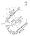
- FIGS. 1A-1Bshow an isometric view of an external fixation device having a ring element and two adjustable devices having k-wires mounted thereon attached to the parts according to the present invention
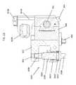
- FIG. 2Ashows an enlarged isometric view of the adjustable device shown in FIG. 1 ;
- FIG. 2Bshows an enlarged view of area A of FIG. 2A showing a ring coupling element
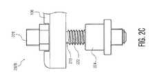
- FIG. 2Cis an enlarged view of an alternate ring coupling element of the present invention used in FIG. 3A ;
- FIG. 3Ais an isometric view of an adjustable device showing the interaction between a first member and a body that enables the first member to move up and down (i.e., perpendicular to a planar surface on the ring element);
- FIG. 3Bis an isometric view from lines 3 - 3 of FIG. 2A and shows the internal gearing that enables a second member to pivot with respect to the ring element;
- FIG. 3Cis an exploded view of the moveable third member and second member shown in FIG. 2A as well as a threaded rod that enables the third member to move linearly with respect to the circumference of the ring element;
- FIG. 3Dis a cross-sectional view showing the member of FIG. 3C assembled
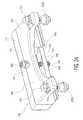
- FIG. 4is a rear view of the adjustable device of FIG. 4 in a first position
- FIG. 5is an isometric end view of the adjustable device of FIG. 4 in a second position
- FIGS. 6A and 6Bare exploded views of an adjustable device of FIG. 2A showing the body, the first member, the second member, and the third member;
- FIGS. 7A-7Bare isometric views similar to FIGS. 1A and 1B showing the adjustable device from two different positions;
- FIG. 8Ais an isometric view of an alternate adjustable device allowing two degrees of movement
- FIG. 8Bis a side isometric view of the alternate adjustable device of FIG. 8A ;
- FIG. 9is an exploded view of the alternate adjustable devices of 8 A and 8 B;
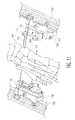
- FIG. 10is a top view of an alternate dynamic external fixator with adjustable members mounted on the inside of the rings;
- FIG. 11is an enlarged isometric view of the ring and adjustable members of FIG. 10 ;
- FIG. 12is a top isometric view of an alternate adjustable device exhibiting two degrees of freedom.
- FIG. 13is a bottom isometric view of the adjustable member of FIG. 12 .
- FIG. 14is a perspective view of another alternate adjustable device.
- FIG. 15is a rear view of the adjustable device of FIG. 14 .
- FIG. 16is a side view of the adjustable device of FIG. 14 .
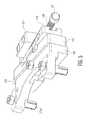
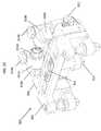
- FIG. 17is a top rear perspective view of a further alternate adjustable device.
- FIG. 18is a rear perspective view of the device of FIG. 17 mated with bone fixation elements.
- FIG. 19is a bottom rear perspective view of the device of FIG. 17 .
- FIG. 20is a top front perspective view of the device of FIG. 17 .
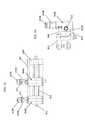
- FIG. 21Ais a side cross-sectional view of a portion of the device of FIG. 17 in a locked position.
- FIG. 21Bis a side cross-sectional view of a portion of the device of FIG. 17 in an unlocked position.
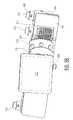
- FIG. 22is a side cross-sectional view of the device of FIG. 17 .
- Dynamic external fixator 100includes a U-shaped ring element 102 having a plurality of mounting holes 103 with at least one adjustable device 104 , and preferably two, releasably attached to a pair of mounting holes 103 .
- Adjustable device 104includes a body 106 releasably attached to arms 108 , 108 ′ of ring element 102 .
- the adjustable devicefurther includes a first member 110 slidably mounted on body 106 capable of providing movement in a direction perpendicular to a proximal surface 109 of arm 108 , 108 ′ of ring element 102 .
- a second member 112pivotally mounts on first member 110 for providing angular movement (i.e., rotation) with respect to first member 110 .
- a third member 114mounts on second member 112 providing linear movement along arms 108 , 108 ′.
- one or more wire engagement elements 116 ′attach first or second k-wires 118 that pass through a fractured bone respectively.
- the wire engagement elementsare mounted to third member 114 and/or to ring 102 directly.
- first k-wire 118attaches to a standard bone engagement element 116 .
- a second k-wire 120can attach directly to ring element 102 .
- second k-wire 120attaches to ring element 102 by being clamped in a standard ring engagement element 122 mounted in a hole 103 .
- first and second k-wires 118 , 120are substantially smooth pins with a drill tip. In some instances, however, first and second k-wires 118 , 120 may not include a drill tip. Further, first and second k-wires 118 , 120 can be made of any suitable material, such as, but not limited to, stainless steel, titanium, and titanium alloy. Further, first and second k-wires 118 , 120 can connect to bone engagement element 116 and ring engagement element 122 by being inserted through a hole (not shown) in bone engagement element 116 or ring engagement element 122 and applying a force on first or second k-wires 118 , 120 by, for example, a set screw (not shown). Alternatively, bone engagement element 116 or ring engagement element 122 can be a wire/rod nut. Any reasonable method for attaching first and second k-wires 118 , 120 to bone engagement element 116 or ring engagement element 122 can be used.
- Ring element 102can be a substantially monolithic material designed to releasably attach to at least one adjustable device 104 .
- Ring element 102can be made of metal (e.g., stainless steel, titanium, etc.), composites (e.g., Carbon PEEK, etc.), or any other material deemed suitable.
- metale.g., stainless steel, titanium, etc.
- compositese.g., Carbon PEEK, etc.
- Ring element 102can include any shape that allows at least one adjustable device to be releasably connected to it.
- ring element 102can be a circle shape, horseshoe shape, square shape, rectangle shape, or any other shape deemed suitable.
- Ring element 102preferably is planar creating a relatively flat surface on ring element 102 .
- This flat surfaceis used to provide a flat surface to releasably attach ring element 102 with adjustable device 104 .
- a ringcan have four levels as shown in U.S. patent application Ser. No. 12/157,612 filed Jun. 11, 2008, the disclosure of which is incorporated herein by reference.
- Adjustable device 104has a body 106 with a pair of expandable connectors 202 A that releasably connect adjustable device 104 to holes 103 of ring element 102 .
- Attached to body 106is first member 110 which slidably mounts on body 106 . While mounted on body 106 , when fixed on ring 102 , first member 110 can move up and down with respect to top planar surface 206 of body 106 . That is, first member 110 can move in a direction perpendicular to upper surface 206 of body 106 and the plane of the ring 102 . This is accomplished by the rotating threaded pin 316 as will be described below. Further, because, in the preferred embodiment, surface 206 of body 106 is parallel to the plane of ring element 102 (see, FIGS. 1A-1B ) first member 110 moves in a direction perpendicular to the plane of ring element 102 .
- preferred connector 202 Aincludes a lower outer portion 215 located under body 106 split into two sections 214 , 216 and an inner portion 217 with a drive head 208 located above body 106 for engaging a drive tool. Further, inner portion 217 has a threaded shaft 212 coupled to drive head 208 and extends between the two halves 214 , 216 . Threaded shaft 212 includes tapered nut 218 which when moved toward body 106 caused sections 214 and 216 to expand. After connector 202 A is placed through body 106 and into hole 103 in the ring element 102 , nut 218 is threaded on the bottom of threaded shaft 212 .
- the split portioncan include any number of sections (e.g., three or four sections).
- ring connector 202 Bcan include a shaft 219 with a screw thread portion 222 and a drive head 221 .
- the threaded shaft portion 222is inserted through the bore in body 106 until drive head 221 comes into contact with upper surface body 106 .
- Threaded shaft portion 222is further inserted through an opening 103 in ring element 102 and threaded into a nut 224 .
- adjustable device 104is secured onto ring element 102 .
- any method of releasably securing adjustable device 104 to the ring elementcan be used.
- the adjustable devicecan be releasably attached to the ring element by a screw and nut, a bolt assembly, or any other securing method deemed suitable.
- First member 110has a first portion 113 and a central portion 306 which can move in a direction perpendicular to the plane of ring element 102 by rotating a screw shaft 302 via drive head 308 .
- Screw shaft 302is placed through a hole 115 in body 106 and is threaded into a second threaded hole 117 located in central flange 306 extending rearwardly from first portion 113 of first member 110 .
- Shaft 302has an end 338 with a pin 340 to ensure the assembly does not come apart during use.
- a userrotates a drive head 308 causing screw 302 to thread into the second hole thereby moving first member 110 up and down with respect to body 106 (i.e., perpendicular to planar surface 206 of body 106 and perpendicular to the plane of ring element 102 ).
- screw shaft 302is described as threaded into a second hole in member 110
- screw 302may thread into a threaded hole in body 106 and fixed in part 306 . It will be understood that any method of making first member 110 move up and down with respect to body 106 can be used. Further, increasing the number of threads on screw shaft 302 increases the number of rotations needed to move first member 110 up and down. Thus, increasing the number of threads increases the precision of up and down movement.
- flange 306 extending from first member 110is designed to ride along a protruding track 310 extending from body 106 . Riding on track 310 reduces the amount of movement in an undesired direction.
- any method of mating first member 110 with body 106 designed to decrease movement in an undesired directioncan be used.
- first member 110 and body 106can include any male-female mating features (e.g., tongue and groove or dovetail) for providing guided movement up and down.
- second member 112is rotatably mounted on first member 110 . While mounted on first member 110 , second member 112 can rotate through a range of angles with respect to first member 110 . That is, second member 112 is pivotally mounted by guide tracks 612 on first member 110 and can rotate with respect to first member 110 . For example, in the preferred embodiment, second member 112 can pivot up to 120 degrees around its center on guide 614 mounted on first member 110 as shown in FIG. 6A . That is, second member 112 can, for example, rotate 60 degrees from parallel in an upward direction and 60 degrees in a downward direction with respect to surface 306 .
- second member 112rotates through a range of angles by the interaction of a worm 312 (i.e., a gear in the form of a screw) with an arcuate worm gear 314 mounted on second member 112 on the outer surface of the portion thereof forming track 612 (i.e., a worm wheel).
- worm 312can thread into worm gear 314 causing second member 112 to rotate relative to first member 110 .
- a userrotates drive head 316 of worm 312 causing worm 312 to rotate while engaged with worm gear 314 .
- first member 110is attached to body 106 that is fixed to ring element 102 , rotating worm 312 while engaged with worm gear 314 causes second member 112 to rotate upwardly or downwardly with respect to the plane of ring 102 .
- the anglecan be changed by spur gears, helical gears, double helical gears, bevel gears, crown gears, or any other gearing deemed suitable.
- increasing the number of threadsi.e., increasing the number of threads on the worm gear and worm
- increasing the number of threadsprovides a greater level of precision during rotation.
- third member 114is mounted on second member 112 . While mounted on second member 112 , third member 114 can move linearly with respect to second member 112 . That is, third member 114 can linearly move along arms 108 , 108 ′ of the ring element in a direction parallel to the plane of ring 102 in an anterior-posterior direction.
- third member 114includes a dovetail protrusion 322 (i.e., guide element) that mates with a groove 324 extending along second member 112 .
- Protrusions 322mates with groove 322 thereby providing a guide for the linear motion.
- a male dovetail protrusion 322 extending from third member 114can mate with a female dovetail 324 located on second member 112 thereby providing a linear guide between second member 112 and third member 114 .
- Any form of male and female guide elementscan be used to provide a linear guide between third member 114 and second member 112 .
- second member 112includes a bore 326 for receiving an end 327 of a threaded rod 328 .
- third member 114can translate on threaded rod 328 as it is rotated via drive head 331 or 332 . Translation is possible because third member 114 includes a threaded bore 330 for receiving threaded rod 328 . Thus, rotating threaded rod 328 translates third member 114 along the axis of threaded rod 328 .
- a userrotates drive head 331 or 332 causing threaded rod 328 to rotate in bore 333 of third member 114 thereby causing third member 114 to move linearly along arm 108 , 108 ′ of ring element 102 .
- any reasonable method for moving third member 114 linearlycan be used.
- increasing the number of threads/grooves on third member 114 and the number of threads/grooves on rod 328increases the amount of precision in linearly moving third member 114 . In the preferred embodiment, one rotation moves member 114 about one millimeter.
- first member 110has not moved perpendicular to planar surface 206 of body 106 .
- second member 112has not been rotated with respect to first member 110 .
- third member 114is depicted in a first position.
- first member 110has been displaced perpendicularly to planar surface 206 of body 106 .
- second member 112has rotated with respect to first member 110 .
- third member 114is depicted in a second position where it has moved linearly with respect to second member 112 .
- FIGS. 6A and 6Bthere is shown an exploded view of adjustable device 104 of the preferred embodiment illustratively depicts the internal contact surfaces for each of body 106 , first member 110 , and second member 112 .
- body 108includes internal planar surface 602 which contacts internal planar surface 604 of first member 110 .
- These planar surfacesprovide a guide surface as first member 110 is displaced in a direction perpendicular to the plane of ring 102 .
- internal planar surfaces 602 , 604are substantially smooth surfaces permitting low friction sliding movement.
- internal planar surfaces 602 , 604can include male and female protrusions (not shown) for allowing movement only perpendicular to planar surface 206 of body 106 .
- first member 110contacts an internal planar surface 608 of second member 112 .
- second member 112contacts an internal planar surface 608 of second member 112 .
- track 612which is in the form of an arcuate guide surface that rides on an arcuate guide element 614 which is attached to a planar surface 616 located on first member 110 .
- track 612provides a center of rotation centrally located on first member 110 .
- Disc 614attaches to planar surface 616 by, for example, screws 618 threaded into holes 620 located in first member 110 . Because track 612 rides on disc 614 motion in any direction other than the desired angular rotation direction is minimized.
- Gear teeth 315are provided on the outer surfaces of track 612 which are driven by worm 312 .
- a lock element 350may be provided to lock second member 112 in the desired angular position.
- third member 114includes a male dovetail protrusion 610 that mates with a female guide surface 609 acting as a guiding surface when third member 114 moves linearly.
- a male dovetail protrusion 610that mates with a female guide surface 609 acting as a guiding surface when third member 114 moves linearly.
- adjustable device 104can move only in the anterior-posterior and inferior-posterior directions.
- an alternate adjustable device 700can include a body 702 attached to a ring element 704 . Further mounted on body 702 is a first member 706 providing movement perpendicular to body 702 by rotation of screw 714 and a second member 708 mounted on first member 706 providing linear movement along arms 710 of ring element 704 by rotation of screw 712 . In this embodiment there is no rotational movement between member 706 and 702 .
- first member 706 mounted on body 702provides movement perpendicular to body 702 .
- second member 708 mounted on first member 706provides motion parallel to the plane of the ring.
- a scalecan be located on at least one of first member 110 and second member 112 . This scale can be used to determine the length of angular or linear displacement by the member. Further, a scale can be located on any of the body, first member, second member, or third member for respectively determining the amount of linear, angular, or circumferential movement of each of the members.
- FIGS. 8A-9there is shown an alternate adjustable device as shown in FIGS. 8A and 8B .
- the devicegenerally denoted as 700 includes a body 702 , first member 706 and second member 708 but does not provide rotational movement between member 706 and 702 as in adjustable device 104 ( FIG. 5 ). Movement parallel to the ring is accomplished by turning screw shaft 712 to move element 708 and movement perpendicular to the ring is accomplished by turning screw shaft 714 and moving element 706 in relation to body 702 .
- Pin holdercan be located in one or both of holes 718 .
- FIG. 9shows an exploded view of the alternate adjustable device 700 including body 702 and element 708 slidably mounted in a groove 716 in member 706 via a dovetail extension 728 and sliding element 708 .
- screw 712is rotated in a threaded bore 720 of element 708 to cause the movement of element 708 parallel to the ring arm 710 .
- Element 706 and body 702includes contacting surfaces 722 and 724 respectively. These surfaces contact when the element 706 is moved in a direction perpendicular to the plane of the ring by turning screw 714 in threaded bore 725 . This movement may be guide by tongue and groove interconnection as in device 104 .
- FIGS. 10 and 11there is shown a top view of an alternate system in which the adjustable device 700 is mounted on the inner surface 730 of ring 704 . Again, Kirschner wires 118 and 120 may be engaged with a foot 101 .
- FIGS. 10 though 13there is shown as an alternate adjustable device 700 ′ which is similar to adjustable device 700 with the exception that a second pin holder 740 is attached to a block 742 which is slidably mounted within the groove 716 of element 706 .
- Block 742has a threaded bore which is mounted on screw shaft 712 and is moveable with respect to element 706 .
- First block 708 Ais also provided with a pin holder and is operated as block 708 . This allows the mounting of two Kirschner wires on element 706 with both Kirschner wires being adjustable along the length of the arm 710 .
- screw shaft 714allows the block 706 to move in the direction perpendicular to the plane of arm 710 .
- indicators scales 746 and 748may be provided to indicate the amount of movement of the Kirschner wires in millimeters.
- FIGS. 14-16there are shown multiple views of another alternate adjustable device 800 which is similar to adjustable device 700 ′.
- the devicegenerally denoted as 800 includes a body 802 , first member 806 and second members 808 A and 808 B.
- First and second members 808 A and 808 Beach include a dovetail 828 B extending from first and second members 808 A and 808 B that is slidably mounted in a groove 816 in member 806 .
- the device 800provides rotational movement between member 806 and 808 A and 808 B, but in different manner than first member 110 and second member 112 of device 100 as shown in FIG. 5 , for example. This rotation is described in further detail below.
- Movement parallel to the ringis accomplished by rotating actuation member 812 (i.e. head of threaded rod) either clockwise or counterclockwise to translate elements 808 A and 808 B, while movement perpendicular to the ring is accomplished by rotating actuation member 814 (i.e. head of a threaded rod) either clockwise or counterclockwise to translate element 806 in relation to body 802 .
- Pin holders 818 A and 818 Bare operatively coupled to elements 808 A and 808 B, respectively.
- Pinsmay be secured within apertures 815 of pin holders 818 A and 818 B.
- Each pin holder 818 A and 818 Bmay be rotated about an axis parallel to the axis of the tibia. The rotation may be effectuated, for example, by coupling a tool (not shown) to a nut 819 A or 819 B and rotating the nut. The rotation of the nut 819 A or 819 B causes the respective pin holder 818 A or 818 B to rotate as well.
- the elements 808 A and 808 B, to which the pin holders 818 A and 818 B are connected,do not rotate by virtue of their connection to screw shaft 812 and first member 806 .
- FIGS. 17-20illustrate various views of yet a further embodiment of an adjustable device 900 .
- Adjustable device 900is similar to adjustable device 800 , and provides for an additional degree of rotation.
- the device generally denoted as 900includes a body 902 , and first member 906 and second members 908 A and 908 B.
- First and second members 908 A and 908 Bare slidably mounted in a groove 916 in member 906 via dovetails extending from the respective sliding element.
- the device 900provides for two degrees of rotational movement between member 906 and 908 A and 908 B. This rotation is described in further detail below.
- Movement parallel to the ringis accomplished by turning screw shaft 912 to move elements 908 A and 908 B, while movement perpendicular to the ring is accomplished by turning screw shaft 914 and moving element 906 in relation to body 902 .
- Pin holders 918 A and 918 Bare rotatably coupled to vertical connectors 921 A and 921 B respectively.
- Pinsmay be secured within apertures of pin holders 918 A and 918 B, as illustrated in FIG. 18 .
- Each pin holder 918 A and 918 Bmay be rotated about an axis parallel to the ring. The rotation may be effectuated, for example, by coupling a tool (not shown) to a nut 923 A or 923 B and rotating the nut. The rotation of the nut 923 A or 923 B causes the respective pin holder 918 A or 918 B to rotate as well.
- vertical connectors 921 A and 921 Bmay each be rotated about an axis parallel to the tibia.
- the rotation of the nut 919 A or 919 Bmay similarly be effectuated by a tool (not shown).
- the elements 908 A and 908 B, to which the pin holders 918 A and 918 B and vertical connectors 921 A and 921 B are connected,do not rotate by virtue of their connection to screw shaft 912 and first member 906 .
- FIGS. 21A and 21Billustrate cross sectional views of second member 908 B in a locked position and an unlocked position, respectively.
- a locking mechanismgenerally includes a rotatable nut 994 , a compression pad 993 , and a locking ball 992 .
- the nut 994is threadingly mated with an aperture in the second member 908 B. As a user rotates the nut 994 , the nut threads into the aperture until the compression pad 993 pushes the locking ball 992 into frictional engagement with the screw shaft 912 . With enough force applied, the compression fit resists free sliding motion of the second member 908 B along the screw shaft 912 .
- the second member 908 BWhen in the locked position, as illustrated in FIG. 21A , the second member 908 B can be translated along the screw shaft 912 by rotation of the screw shaft, as described above.
- the second element 908 BWhen in the unlocked position, as illustrated in FIG. 21B , the second element 908 B can be freely translated along the screw shaft 912 without rotating the screw shaft.
- a spring 991 and ball 990are also translated along the screw shaft 912 .
- the spring 991biases the ball 990 toward the screw shaft 912 .
- the ball 990helps locate the grooves of the threaded screw shaft 912 due to the force provided by the spring 991 .
- the locking mechanismmay also include a fitting in the form of a ball 995 .
- the ball 995may fit into a corresponding groove in the aperture of the second element 908 B.
- the ball 995may also be located between two flanges on the nut 994 and sized such that, even upon continued rotation of the nut 994 in the unlocking direction, the nut resists complete disengagement from the aperture of the second member 908 B. Similar or identical mechanisms to those described with relation to second member 908 B can be provided for second member 908 A for the same purposes.
- second members 908 A and 908 Bcan be freely translated along the screw shaft 912 independently of each other. When each is locked, however, rotation of the screw thread 912 translates the second members 908 A and 908 B in unison.
- the device 900includes a clamping mechanism that allows for connection of the device to rings of various thicknesses.
- the body 902includes a pair of connector systems 1002 (only one connector system visible in FIG. 22 ).
- the connector system 1002generally includes a connector 1004 with a head 1006 and a threaded portion 1008 .
- the threaded portion 1008 and part of the connector 1004pass through a hole in a fixation ring, and the threaded portion threadingly engages an aperture 903 in the body 902 to secure the fixation ring relative to the body 902 .
- the connector system 1002also includes a nut 1010 which is threadedly secured to a clamp 1014 , the nut 1010 and clamp 1014 acting as a single body.
- the nut 1010is flush on the collar 1012 of head 1006 .
- the connector system 1002may initially be in an open position that provides enough clearance for a fixation ring to be inserted into the body 902 (this position not illustrated). Once inserted into the body 902 , a hole in the fixation ring is aligned with the connector system and the threaded portion 1008 of the connector 1004 is advanced through a hole in the fixation ring. This may initially be accomplished by pushing the head 1006 of the connector 1004 upwards until the threaded portion 1008 is adjacent to the threaded aperture 903 in the body 902 . At that point, the head 1006 is rotated as the threads of the threaded portion 1008 engage the threaded aperture 903 .
- a top flange of the clamp 1014advances with the connector 1004 until it contacts a face of the fixation ring.
- the flange of the clamp 1014provides a surface on which a bottom face of a fixation ring rests, and thus allows for rings of various thicknesses to be securedly supported by the body 902 in conjunction with the connector system 1002 .
- Additional clamps, such as second clamp 1016may also be used to allow for secured fixation of thinner fixation rings.
Landscapes
- Health & Medical Sciences (AREA)
- Orthopedic Medicine & Surgery (AREA)
- Life Sciences & Earth Sciences (AREA)
- Surgery (AREA)
- Medical Informatics (AREA)
- Engineering & Computer Science (AREA)
- Biomedical Technology (AREA)
- Heart & Thoracic Surgery (AREA)
- Nuclear Medicine, Radiotherapy & Molecular Imaging (AREA)
- Molecular Biology (AREA)
- Animal Behavior & Ethology (AREA)
- General Health & Medical Sciences (AREA)
- Public Health (AREA)
- Veterinary Medicine (AREA)
- Neurology (AREA)
- Surgical Instruments (AREA)
Abstract
Description
Claims (22)
Priority Applications (2)
| Application Number | Priority Date | Filing Date | Title |
|---|---|---|---|
| US13/788,466US8906020B2 (en) | 2009-10-05 | 2013-03-07 | Dynamic external fixator and methods for use |
| EP14154811.5AEP2774562A1 (en) | 2013-03-07 | 2014-02-12 | Dynamic external fixator and methods for use |
Applications Claiming Priority (2)
| Application Number | Priority Date | Filing Date | Title |
|---|---|---|---|
| US12/573,310US8858555B2 (en) | 2009-10-05 | 2009-10-05 | Dynamic external fixator and methods for use |
| US13/788,466US8906020B2 (en) | 2009-10-05 | 2013-03-07 | Dynamic external fixator and methods for use |
Related Parent Applications (1)
| Application Number | Title | Priority Date | Filing Date |
|---|---|---|---|
| US12/573,310Continuation-In-PartUS8858555B2 (en) | 2009-10-05 | 2009-10-05 | Dynamic external fixator and methods for use |
Publications (2)
| Publication Number | Publication Date |
|---|---|
| US20130253512A1 US20130253512A1 (en) | 2013-09-26 |
| US8906020B2true US8906020B2 (en) | 2014-12-09 |
Family
ID=43823776
Family Applications (4)
| Application Number | Title | Priority Date | Filing Date |
|---|---|---|---|
| US12/573,310Active2030-09-17US8858555B2 (en) | 2009-10-05 | 2009-10-05 | Dynamic external fixator and methods for use |
| US13/788,466Active2029-11-03US8906020B2 (en) | 2009-10-05 | 2013-03-07 | Dynamic external fixator and methods for use |
| US14/483,363ActiveUS9351763B2 (en) | 2009-10-05 | 2014-09-11 | Dynamic external fixator and methods for use |
| US15/138,722Active2030-05-20US10149701B2 (en) | 2009-10-05 | 2016-04-26 | Dynamic external fixator and methods for use |
Family Applications Before (1)
| Application Number | Title | Priority Date | Filing Date |
|---|---|---|---|
| US12/573,310Active2030-09-17US8858555B2 (en) | 2009-10-05 | 2009-10-05 | Dynamic external fixator and methods for use |
Family Applications After (2)
| Application Number | Title | Priority Date | Filing Date |
|---|---|---|---|
| US14/483,363ActiveUS9351763B2 (en) | 2009-10-05 | 2014-09-11 | Dynamic external fixator and methods for use |
| US15/138,722Active2030-05-20US10149701B2 (en) | 2009-10-05 | 2016-04-26 | Dynamic external fixator and methods for use |
Country Status (1)
| Country | Link |
|---|---|
| US (4) | US8858555B2 (en) |
Cited By (6)
| Publication number | Priority date | Publication date | Assignee | Title |
|---|---|---|---|---|
| US20140378972A1 (en)* | 2009-10-05 | 2014-12-25 | Stryker Trauma Sa | Dynamic external fixator and methods for use |
| US9522023B2 (en)* | 2011-12-09 | 2016-12-20 | Zimmer Gmbh | Orthopedic plate, orthopedic device, method of coupling bone segments, and method of assembling an orthopedic plate |
| US9717527B2 (en) | 2010-08-11 | 2017-08-01 | Stryker European Holdings I, Llc | External fixator system |
| US9730730B2 (en) | 2010-08-11 | 2017-08-15 | Stryker European Holdings I, Llc | External fixator system |
| US9820775B2 (en) | 2012-08-23 | 2017-11-21 | Styker European Holdings I, LLC | Bone transport external fixation frame |
| US11141196B2 (en) | 2010-08-11 | 2021-10-12 | Stryker European Operations Holdings Llc | External fixator system |
Families Citing this family (33)
| Publication number | Priority date | Publication date | Assignee | Title |
|---|---|---|---|---|
| JP5497194B2 (en) | 2009-12-11 | 2014-05-21 | スモール・ボーン・イノベーションズ・インコーポレーテッド | Ankle fusion device, instrument, and method |
| GB201008281D0 (en) | 2010-05-19 | 2010-06-30 | Nikonovas Arkadijus | Indirect analysis and manipulation of objects |
| US9023045B2 (en) | 2010-10-28 | 2015-05-05 | Stryker Trauma Sa | Bolt and tool with anti-torque features |
| EP2446841B1 (en) | 2010-10-28 | 2013-05-29 | Stryker Trauma SA | Bolt and tool with anti-torque features |
| US8906021B1 (en) | 2012-08-20 | 2014-12-09 | Stryker Trauma Sa | Telescopic strut for an external fixator |
| WO2014055202A1 (en)* | 2012-09-06 | 2014-04-10 | Solana Surgical LLC | External fixator |
| US9155561B2 (en) | 2013-03-06 | 2015-10-13 | Stryker Trauma Sa | Mini-rail external fixator |
| EP2774562A1 (en)* | 2013-03-07 | 2014-09-10 | Stryker Trauma SA | Dynamic external fixator and methods for use |
| EP2937049B1 (en) | 2013-03-11 | 2019-05-08 | Stryker Trauma SA | External fixator system |
| CN105050517B (en)* | 2013-03-13 | 2019-01-01 | 德普伊新特斯产品公司 | External bone fixation devices |
| US10258377B1 (en)* | 2013-09-27 | 2019-04-16 | Orthex, LLC | Point and click alignment method for orthopedic surgeons, and surgical and clinical accessories and devices |
| US9962188B2 (en) | 2013-10-29 | 2018-05-08 | Cardinal Health 247. Inc. | External fixation system and methods of use |
| WO2016166236A1 (en)* | 2015-04-15 | 2016-10-20 | Umc Utrecht Holding B.V. | Coupling device for in an orthopaedic system |
| US10531896B2 (en) | 2015-08-10 | 2020-01-14 | Stryker European Holdings I, Llc | Distraction tube with wire clamp |
| CN105708530B (en)* | 2016-01-22 | 2018-08-10 | 叶智江 | Finger miniature external fixing rack |
| AU2017217654B2 (en) | 2016-02-09 | 2019-10-03 | Amdt Holdings, Inc. | External bone fixation systems |
| US9795411B2 (en) | 2016-03-02 | 2017-10-24 | Globus Medical, Inc. | Fixators for bone stabilization and associated systems and methods |
| US10010350B2 (en) | 2016-06-14 | 2018-07-03 | Stryker European Holdings I, Llc | Gear mechanisms for fixation frame struts |
| WO2017221243A1 (en)* | 2016-06-19 | 2017-12-28 | Orthospin Ltd. | User interface for strut device |
| US10835318B2 (en) | 2016-08-25 | 2020-11-17 | DePuy Synthes Products, Inc. | Orthopedic fixation control and manipulation |
| CN106725782A (en)* | 2016-12-24 | 2017-05-31 | 北京工业大学 | A kind of collapsible exter-nal fixer in parallel |
| US10874433B2 (en) | 2017-01-30 | 2020-12-29 | Stryker European Holdings I, Llc | Strut attachments for external fixation frame |
| EP3384863A1 (en) | 2017-04-07 | 2018-10-10 | Kyon AG | Modular external fixator |
| FR3069352B1 (en)* | 2017-07-24 | 2019-08-30 | Beweis | SYSTEM AND METHOD FOR REPERTING A RADIOGRAPHIC OBJECT |
| CN108478266B (en)* | 2018-03-26 | 2020-11-06 | 天津大学 | Free-connection three-branch parallel orthopaedic external fixator |
| US11439436B2 (en) | 2019-03-18 | 2022-09-13 | Synthes Gmbh | Orthopedic fixation strut swapping |
| US11304757B2 (en) | 2019-03-28 | 2022-04-19 | Synthes Gmbh | Orthopedic fixation control and visualization |
| CN110664477B (en)* | 2019-10-15 | 2024-12-27 | 温州医科大学附属第二医院、温州医科大学附属育英儿童医院 | Kirschner wire introducer for internal fixation of phalanx fractures |
| CN110693586B (en)* | 2019-11-04 | 2024-08-20 | 华中科技大学同济医学院附属协和医院 | External fixator for crossed Kirschner wire |
| US11334997B2 (en) | 2020-04-03 | 2022-05-17 | Synthes Gmbh | Hinge detection for orthopedic fixation |
| CN113057595B (en)* | 2021-03-24 | 2023-07-14 | 中国中医科学院望京医院(中国中医科学院骨伤科研究所) | Spinal motion segment in-vivo loading device |
| US11944352B2 (en) | 2021-05-28 | 2024-04-02 | William Casey Fox | Extracorporeal bone compressing link and apparatus and method using same |
| US11457965B1 (en) | 2021-11-12 | 2022-10-04 | University Of Utah Research Foundation | Rotational guided growth devices, systems, and methods |
Citations (162)
| Publication number | Priority date | Publication date | Assignee | Title |
|---|---|---|---|---|
| US6214A (en) | 1849-03-20 | Surgical apparatus for fractured or injured ankles | ||
| US2333033A (en) | 1943-06-11 | 1943-10-26 | Leslie E Mraz | Bone splint |
| US2391537A (en) | 1943-09-27 | 1945-12-25 | Anderson Roger | Ambulatory rotating reduction and fixation splint |
| US2393831A (en) | 1942-12-29 | 1946-01-29 | Stader Otto | Bone splint |
| US3727610A (en) | 1971-03-16 | 1973-04-17 | P Riniker | Fixator for diaphyses fractures |
| US3985127A (en) | 1975-06-11 | 1976-10-12 | Mstislav Vasilievich Volkov | Apparatus for surgical treatment of the knee joint |
| CH596826A5 (en) | 1975-12-18 | 1978-03-31 | Tsnii Travmatologii I Ortopedi | Surgical braces for fractured bones |
| US4100919A (en) | 1976-12-08 | 1978-07-18 | Tsentralny Nauchno-Issledovatelsky Institut Travmatologii I Ortopedii Imeni N.N. Priorova | Apparatus for surgical treatment of bones and joints |
| US4185623A (en) | 1978-07-18 | 1980-01-29 | Oganesian Oganes V | Apparatus for restoration of hip joint mobility |
| US4338927A (en) | 1981-03-16 | 1982-07-13 | Volkov Mstislav V | Device for restoring the function of the lower extremities |
| US4548199A (en) | 1981-11-13 | 1985-10-22 | Agee John M | Fracture splint |
| FR2576774A1 (en) | 1985-02-07 | 1986-08-08 | Issoire Aviat Sa | Device for three-dimensional positioning of any two pieces, in particular two pieces of bone, and allowing modification of the said positioning |
| US5074866A (en) | 1990-10-16 | 1991-12-24 | Smith & Nephew Richards Inc. | Translation/rotation device for external bone fixation system |
| US5087258A (en) | 1987-06-19 | 1992-02-11 | Thomas Schewior | Ring splint to set, affix and regulate the tension position of bone segments |
| US5112331A (en) | 1989-06-15 | 1992-05-12 | Vel Miletich | Orthopedic pins for external fixator |
| US5122140A (en) | 1989-08-23 | 1992-06-16 | Jaquet Orthopedie, S.A. | Dynamic external fixation device |
| US5207676A (en) | 1989-02-27 | 1993-05-04 | Jaquet Orthopedie S.A. | External fixator with controllable damping |
| EP0611007A1 (en) | 1993-02-12 | 1994-08-17 | Bristol-Myers Squibb Company | Adjustable connector for external fixation rods |
| US5353504A (en) | 1993-04-30 | 1994-10-11 | Pai Chung Jen | Motorized scissors |
| US5391167A (en) | 1992-09-01 | 1995-02-21 | Ortho-Motion, Inc. | Articulating external fixation device |
| US5437666A (en) | 1992-08-24 | 1995-08-01 | Synthes (U.S.A.) | External fixation device for osteosynthesis |
| US5451225A (en) | 1993-06-10 | 1995-09-19 | Texas Scottish Rite Hospital For Crippled Children | Fastener for external fixation device wires and pins |
| US5540686A (en) | 1993-02-18 | 1996-07-30 | Endocare Ag | Apparatus for lengthening bones |
| US5658283A (en) | 1995-02-15 | 1997-08-19 | Huebner; Randall J. | External fixator for repairing fractures |
| US5662648A (en) | 1993-03-15 | 1997-09-02 | Orthofix S.R.L. | Method and apparatus for the external setting of fractures |
| US5681309A (en) | 1993-06-10 | 1997-10-28 | Texas Scottish Rite Hospital For Crippled Children | Distractor mechanism for external fixation device |
| US5688271A (en) | 1994-03-07 | 1997-11-18 | Orthofix S.R.L. | Orthopaedic device, especially for the gradual correction of fractures |
| US5702389A (en) | 1995-03-01 | 1997-12-30 | Smith & Nephew Richards, Inc. | Orthopaedic fixation device |
| US5713897A (en) | 1997-03-06 | 1998-02-03 | Goble; E. Marlowe | Anterior cruciate ligament tensioning device and method for its use |
| US5725526A (en) | 1995-11-27 | 1998-03-10 | Zimmer, Inc. | Transport carriage for an external fixator |
| US5725527A (en) | 1992-09-10 | 1998-03-10 | Biedermann Motech Gmbh | Anchoring member |
| US5728095A (en) | 1995-03-01 | 1998-03-17 | Smith & Nephew, Inc. | Method of using an orthopaedic fixation device |
| US5776173A (en) | 1997-06-04 | 1998-07-07 | Madsen, Jr.; Ronald E. | Programmable interferential stimulator |
| US5776132A (en) | 1996-12-26 | 1998-07-07 | Blyakher; Arkady | External fixation assembly |
| US5788695A (en) | 1993-12-15 | 1998-08-04 | Richardson; James Bruce | Patient-operated orthopedic devices |
| US5797908A (en) | 1997-02-04 | 1998-08-25 | Bristol-Myers Squibb Company | External fixator assembly and clamp therefor |
| US5846245A (en) | 1995-10-20 | 1998-12-08 | New York University | Bone-adjusting device |
| US5863292A (en) | 1996-09-26 | 1999-01-26 | Tosic; Aleksandar | Articulated external orthopedic fixation system and method of use |
| US5891143A (en) | 1997-10-20 | 1999-04-06 | Smith & Nephew, Inc. | Orthopaedic fixation plate |
| US5897555A (en) | 1997-05-15 | 1999-04-27 | Wright Medical Technology, Inc. | External fixation system and method |
| US5919192A (en) | 1997-06-10 | 1999-07-06 | Cottec Orthopaedic Technologies Development Ltd. | Compression-distraction apparatus for treatment of a bone fracture |
| US5921985A (en) | 1998-02-10 | 1999-07-13 | Texas Scottish Rite Hospital | External fixation device and method |
| US5931837A (en) | 1997-12-09 | 1999-08-03 | University Of Iowa Research Foundation | Method and apparatus for external fixation of an ankle |
| US5971984A (en) | 1995-03-01 | 1999-10-26 | Smith & Nephew, Inc. | Method of using an orthopaedic fixation device |
| US5976133A (en) | 1997-04-23 | 1999-11-02 | Trustees Of Tufts College | External fixator clamp and system |
| US6007535A (en) | 1996-01-03 | 1999-12-28 | John M. Rayhack | Multi-plane bone distraction system |
| US6010501A (en) | 1997-12-15 | 2000-01-04 | Electro-Biology, Inc. | Method and apparatus for external fixation of small bones |
| US6013081A (en) | 1998-09-09 | 2000-01-11 | Sulzer Orthopedics Inc. | Apparatus and method for anterior and posterior referenced sizing and distal femur resection |
| US6030386A (en) | 1998-08-10 | 2000-02-29 | Smith & Nephew, Inc. | Six axis external fixator strut |
| US6245071B1 (en) | 1999-03-10 | 2001-06-12 | Synthes (U.S.A.) | External fixation device for bone |
| US20010049526A1 (en) | 2000-05-09 | 2001-12-06 | Daniele Venturini | Securing component for a ring fixator used in orthopaedic surgery |
| US6328737B1 (en) | 1997-04-11 | 2001-12-11 | Keel University | Fracture reduction device |
| US6342052B1 (en) | 1999-11-02 | 2002-01-29 | Hector D. Allende | Anorectal apparatus |
| US6342054B1 (en) | 1998-12-29 | 2002-01-29 | Stryker Trauma Sa | Positioning and locking device |
| US20020013584A1 (en) | 2000-05-24 | 2002-01-31 | Termaten Gerrit J. | Fixing device for orthopedic applications |
| US6423061B1 (en) | 2000-03-14 | 2002-07-23 | Amei Technologies Inc. | High tibial osteotomy method and apparatus |
| US20020165543A1 (en) | 2000-02-02 | 2002-11-07 | Winquist Robert A. | Adjustable bone stabilizing frame system |
| US6491694B1 (en) | 1994-12-05 | 2002-12-10 | Smith & Nephew, Inc. | External fixator for distal radius fractures |
| US20030069580A1 (en) | 2001-10-09 | 2003-04-10 | Langmaid Michael N. | Adjustable fixator |
| US20030106230A1 (en) | 2001-12-10 | 2003-06-12 | Hennessey C. William | Parallel kinematic micromanipulator |
| US6610063B2 (en) | 2000-07-28 | 2003-08-26 | Synthes (Usa) | Spinal fixation system |
| US20030181911A1 (en) | 2000-08-31 | 2003-09-25 | Daniele Venturini | External splint device for reducing bone fractures |
| US20030191466A1 (en) | 2002-04-05 | 2003-10-09 | Ed Austin | Orthopaedic fixation method and device |
| US6648891B2 (en) | 2001-09-14 | 2003-11-18 | The Regents Of The University Of California | System and method for fusing spinal vertebrae |
| US20030216734A1 (en) | 2002-05-20 | 2003-11-20 | Citieffe S.R.L. | External fixation system for treating bone fractures |
| US6652524B1 (en) | 2002-05-30 | 2003-11-25 | Millennium Medical Technologies, Inc. | Fixator with outrigger |
| US20030225406A1 (en) | 2002-05-30 | 2003-12-04 | Millennium Medical Technologies, Inc. | Outrigger for bone fixator |
| EP1016381B1 (en) | 1998-11-23 | 2003-12-10 | Hraklis Kourtis | External fixation system with telescopic pin or arm holding unit |
| US20040097944A1 (en) | 2002-07-30 | 2004-05-20 | Koman L. Andrew | Fixation device and method for treating contractures and other orthopedic indications |
| US20040116926A1 (en) | 2000-05-09 | 2004-06-17 | Daniele Venturini | Ring fixator |
| US20040133199A1 (en) | 2001-03-05 | 2004-07-08 | Michele Coati | External fixation device for reducing bone fractures |
| US20040133200A1 (en) | 2002-11-15 | 2004-07-08 | Ruch David S. | Apparatus and method for maintaining bones in a healing position |
| US6784125B1 (en) | 2000-03-07 | 2004-08-31 | Kanebo, Ltd. | Nonwoven thermoplastic elastomer fabric roll and method and apparatus for making same |
| US20050043730A1 (en) | 2002-02-11 | 2005-02-24 | Pioneer Laboratories, Inc. | External fixation apparatus and method |
| US20050059968A1 (en) | 2003-09-16 | 2005-03-17 | Grant William Peter | Combination bone fixation/immobilization apparatus |
| US20050113829A1 (en) | 2002-07-15 | 2005-05-26 | Ebi, L.P. | Method and apparatus for the external fixation and correction of bone |
| US20050119656A1 (en) | 2002-02-04 | 2005-06-02 | Joseph Ferrante | External fixation system |
| US20050149018A1 (en) | 2003-12-31 | 2005-07-07 | Paul Cooper | External bone/joint fixation device |
| US20050234448A1 (en) | 2004-03-19 | 2005-10-20 | Mccarthy James | Implantable bone-lengthening device |
| US7048735B2 (en) | 2002-02-04 | 2006-05-23 | Smith & Nephew | External fixation system |
| US20060155276A1 (en) | 2005-01-11 | 2006-07-13 | Walulik Stephen B | Bone fixation assembly and related method |
| US20060229605A1 (en) | 2005-03-18 | 2006-10-12 | Olsen Ron A | Adjustable splint for osteosynthesis with incrementing assembly for adjustment in predetermined increments |
| US20060235383A1 (en) | 2005-03-07 | 2006-10-19 | Shane Hollawell | External fixator |
| US20060276786A1 (en) | 2005-05-25 | 2006-12-07 | Brinker Mark R | Apparatus for accurately positioning fractured bone fragments toward facilitating use of an external ring fixator system |
| US7147640B2 (en) | 2003-03-12 | 2006-12-12 | Acumed Llc | External fixator |
| US20060287652A1 (en) | 2005-06-21 | 2006-12-21 | Lessig Richard K | Adjustable fixation clamp and method |
| US20070038217A1 (en) | 2005-08-09 | 2007-02-15 | Brown Daniel G | Orthopaedic fixation clamp and method |
| US20070043354A1 (en) | 2005-08-03 | 2007-02-22 | Koo Terry K | Bone reposition device, method and system |
| US20070049930A1 (en) | 2005-08-25 | 2007-03-01 | Jim Hearn | External fixation system and method of use |
| US20070055233A1 (en) | 2005-08-03 | 2007-03-08 | Brinker Mark R | Apparatus and method for repositioning fractured bone fragments using an arc shaped panel and half pins |
| US20070123857A1 (en) | 2005-10-27 | 2007-05-31 | Deffenbaugh Daren L | Orthopaedic joint, device and associated method |
| US20070161983A1 (en) | 2005-12-08 | 2007-07-12 | Ebi, L.P. | External fixation system |
| US20070161984A1 (en) | 2005-12-08 | 2007-07-12 | Ebi, L.P. | Foot plate fixation |
| US20070225704A1 (en) | 2006-03-23 | 2007-09-27 | Ziran Bruce H | Electromechanically driven external fixator and methods of use |
| US7276069B2 (en) | 2001-01-12 | 2007-10-02 | Biedermann Motech Gmbh | Connector element for bone rods or spinal rods |
| US20070233061A1 (en) | 2006-03-31 | 2007-10-04 | Stryker Trauma S.A. | External fixator element |
| WO2007111576A2 (en) | 2006-03-28 | 2007-10-04 | Ghassan Salameh | External fixation device for treatment of foot deformities and fractures |
| US20070255280A1 (en) | 2003-01-10 | 2007-11-01 | Smith & Nephew, Inc. | External fixation apparatus and method |
| US7291148B2 (en) | 2003-06-03 | 2007-11-06 | John M. Agee Trustee Of The John M. Agee Trust | External fixator for Colles' fracture |
| US20070282338A1 (en) | 2002-09-17 | 2007-12-06 | Ebi, L.P. | Unilateral fixator |
| US7311711B2 (en) | 2001-12-21 | 2007-12-25 | Cole J Dean | Surgical distractor frame |
| US20080228185A1 (en) | 2007-03-15 | 2008-09-18 | Amei Technologies, Inc. | Encompassing external fixation device with incorporated pemf coil |
| US20080269741A1 (en) | 2007-04-28 | 2008-10-30 | John Peter Karidis | Orthopedic fixation device with zero backlash and adjustable compliance, and process for adjusting same |
| US20090018541A1 (en) | 2007-06-27 | 2009-01-15 | Abraham Lavi | Multi-angle clamp |
| US20090036890A1 (en) | 2007-07-31 | 2009-02-05 | John Peter Karidis | Fixator apparatus with radiotransparent apertures for orthopaedic applications |
| US7491008B2 (en) | 2005-02-09 | 2009-02-17 | Stryker Trauma S.A. | External fixation clamp |
| US7507240B2 (en) | 2005-03-18 | 2009-03-24 | Ron Anthon Olsen | Adjustable splint for osteosynthesis |
| US20090105621A1 (en) | 2007-10-18 | 2009-04-23 | Boyd Lawrence M | Protective and Cosmetic Covering for External Fixators |
| US7527626B2 (en) | 2003-10-06 | 2009-05-05 | Stryker Trauma Sa | External fixation element |
| US20090131935A1 (en) | 2007-11-15 | 2009-05-21 | Yeager David A | Method of preparing a patient's leg in need of treatment, for ambulation |
| US20090177198A1 (en) | 2005-12-29 | 2009-07-09 | Matsukidis Theodoros | Compression-distraction device |
| US20090198234A1 (en) | 2008-02-01 | 2009-08-06 | Stryker Trauma Sa | Telescopic strut for an external fixator |
| US7578822B2 (en) | 2005-04-29 | 2009-08-25 | Warsaw Orthopedic, Inc. | Instrument for compression or distraction |
| US20090264883A1 (en) | 2008-04-18 | 2009-10-22 | Stryker Trauma Sa | Radiolucent orthopedic fixation plate |
| US20090287212A1 (en) | 2006-05-26 | 2009-11-19 | National University Corporation Nagoya University | External fixator |
| US7632271B2 (en) | 2005-02-09 | 2009-12-15 | Stryker Trauma S.A. | External mounting device, particularly for extension of a distance between clamping elements |
| US20090312757A1 (en) | 2008-06-17 | 2009-12-17 | Depuy Products, Inc. | External fixator |
| US7699848B2 (en) | 2000-12-14 | 2010-04-20 | Synthes Usa, Llc | Multipin clamp and rod attachment |
| US7708736B2 (en) | 2006-02-22 | 2010-05-04 | Extraortho, Inc. | Articulation apparatus for external fixation device |
| US20100145336A1 (en) | 2001-03-28 | 2010-06-10 | Moximed, Inc. | Bone fixated, articulated joint load control device |
| US20100179548A1 (en) | 2009-01-13 | 2010-07-15 | Marin Luis E | External fixator assembly |
| US20100191239A1 (en) | 2007-06-01 | 2010-07-29 | Umc Utrecht Holding B.V. | System for Correcting Bones |
| US20100234844A1 (en) | 2009-03-10 | 2010-09-16 | Stryker Trauma Sa | Exernal fixation system |
| US7803158B2 (en) | 2004-03-26 | 2010-09-28 | Depuy Products, Inc. | Navigated pin placement for orthopaedic procedures |
| US20100249779A1 (en) | 2009-02-24 | 2010-09-30 | The Hospital For Special Surgery | External fixation devices and methods of use |
| US7806843B2 (en) | 2007-09-25 | 2010-10-05 | Marin Luis E | External fixator assembly |
| US7815586B2 (en) | 2005-03-09 | 2010-10-19 | Ez Concepts Surgical Device Corporation | Adjustable restraint for the lower leg and/or foot |
| US20100280516A1 (en) | 2009-04-30 | 2010-11-04 | Jeffrey Taylor | Accessory Device for an Orthopedic Fixator |
| US20100298827A1 (en) | 2009-05-15 | 2010-11-25 | Stryker Trauma Sa | Fixation clamp |
| US20100305568A1 (en) | 2008-02-05 | 2010-12-02 | Texas Scottish Rite Hospital For Children | External fixator ring |
| US20100312243A1 (en) | 2008-02-08 | 2010-12-09 | Texas Scottish Rite Hospital For Children | External fixator ring |
| US20100331840A1 (en) | 2008-02-12 | 2010-12-30 | Texas Scottish Rite Hospital For Children | Fast adjust external fixation connection rod |
| US20110060336A1 (en) | 2009-09-04 | 2011-03-10 | Ellipse Technologies, Inc. | Bone growth device and method |
| US20110066151A1 (en) | 2009-09-11 | 2011-03-17 | Stryker Trauma Sa | External fixation component |
| US20110082458A1 (en) | 2009-10-05 | 2011-04-07 | Stryker Trauma Sa | Dynamic External Fixator And Methods For Use |
| US20110098707A1 (en) | 2007-09-27 | 2011-04-28 | Extraortho, Inc. | Method and clamping apparatus for external fixation and stabilization |
| US20110112533A1 (en) | 2009-11-06 | 2011-05-12 | Orthofix S.R.L. | Clamp for External Orthopaedic Fixing Device |
| US20110118737A1 (en) | 2009-11-13 | 2011-05-19 | Amei Technologies, Inc. | Fixation device and multiple-axis joint for a fixation device |
| US20110118738A1 (en) | 2009-11-13 | 2011-05-19 | Amei Technologies, Inc. | Adjustable orthopedic fixation system |
| US7955334B2 (en) | 2008-04-18 | 2011-06-07 | Stryker Trauma Sa | External fixation system |
| US20110172664A1 (en) | 2008-09-16 | 2011-07-14 | Orthofix S.R.L. | Orthopaedic device for correcting deformities of long bones |
| US7985221B2 (en) | 2006-04-20 | 2011-07-26 | Millennium Medical Technologies, Inc. | External fixator |
| US20110245830A1 (en) | 2008-09-11 | 2011-10-06 | Thomas Zgonis | Foot, ankle and lower extremity compression and fixation system and related uses |
| US20110313419A1 (en) | 2010-06-22 | 2011-12-22 | Extraortho, Inc. | Hexapod External Fixation System with Collapsing Connectors |
| US20110313418A1 (en) | 2010-05-19 | 2011-12-22 | Arkadijus Nikonovas | Orthopedic fixation with imagery analysis |
| US20120004659A1 (en) | 2010-07-01 | 2012-01-05 | Extraortho, Inc. | Multi-Locking External Fixation Clamp |
| US8114077B2 (en) | 2008-02-01 | 2012-02-14 | Stryker Trauma Sa | Clamping pin |
| EP2417923A1 (en) | 2010-08-11 | 2012-02-15 | Stryker Trauma SA | External fixator system |
| US8142432B2 (en) | 2007-02-05 | 2012-03-27 | Synthes Usa, Llc | Apparatus for repositioning portions of fractured bone and method of using same |
| US20120078251A1 (en) | 2010-09-23 | 2012-03-29 | Mgv Enterprises, Inc. | External Fixator Linkage |
| US8147490B2 (en) | 2005-04-01 | 2012-04-03 | Tantum Ag | Fixation device for stably interlinking at least two bone fragments of a broken bone and corresponding fixation element and kit |
| US20120089142A1 (en) | 2010-10-12 | 2012-04-12 | Extraortho, Inc. | Single Lock External Fixation Clamp Arrangement and Method |
| US8157800B2 (en) | 2007-03-21 | 2012-04-17 | Vvedensky Pyotr S | Computer-aided system for limb lengthening |
| US20120095462A1 (en) | 2010-10-12 | 2012-04-19 | Extraortho, Inc. | External Fixation Surgical Clamp with Swivel |
| US8172849B2 (en) | 2004-05-04 | 2012-05-08 | Synthes Usa, Llc | Midface distractor |
| US8182483B2 (en) | 2008-09-11 | 2012-05-22 | Orthofix S.R.L. | Orthopaedic device to be associated with the outside of a bone |
| US8187274B2 (en) | 2008-06-30 | 2012-05-29 | Depuy Products, Inc. | External fixator |
| US20120136355A1 (en) | 2010-11-30 | 2012-05-31 | Nikolaj Wolfson | Orthopedic fixation systems and methods |
| US8192434B2 (en) | 2008-05-02 | 2012-06-05 | Huebner Randall J | External fixation and foot-supporting device |
| US20120143190A1 (en) | 2010-11-30 | 2012-06-07 | OrthoLan LLC | Orthopedic fixation systems and methods |
| WO2012102685A1 (en) | 2011-01-28 | 2012-08-02 | Isin Tamer | Computer-assisted position identification and management method and apparatus with perpendicular edge geometric arrangement |
| US8282652B2 (en) | 2006-08-02 | 2012-10-09 | The Nemours Foundation | Force-controlled autodistraction |
Family Cites Families (17)
| Publication number | Priority date | Publication date | Assignee | Title |
|---|---|---|---|---|
| US2035952A (en) | 1935-05-20 | 1936-03-31 | Joe J Ettinger | Fracture reduction apparatus |
| US3941123A (en) | 1975-05-20 | 1976-03-02 | Mstislav Vasilievich Volkov | Apparatus for joint movement restitution |
| US4611586A (en)* | 1983-10-06 | 1986-09-16 | John M. Agee | Articulated Colles' fracture splint |
| US4905680A (en)* | 1986-10-27 | 1990-03-06 | Johnson & Johnson Orthopaedics, Inc. | Absorbable bone plate |
| WO1990000882A1 (en) | 1988-07-25 | 1990-02-08 | Vsesojuzny Kurgansky Nauchny Tsentr 'vosstanovitelnaya Travmatologia I Ortopedia' | Traction apparatus for restoring the shape of the hand |
| US4973332A (en)* | 1988-09-12 | 1990-11-27 | Hospital For Joint Diseases | Attachment for femur sliding screw plate |
| CH678485A5 (en) | 1988-12-15 | 1991-09-30 | Jaquet Orthopedie | |
| US5358504A (en)* | 1993-05-05 | 1994-10-25 | Smith & Nephew Richards, Inc. | Fixation brace with focal hinge |
| US5591169A (en)* | 1994-06-14 | 1997-01-07 | Benoist; Louis | Device and method for positioning and holding bone fragments in place |
| US5885282A (en)* | 1997-05-09 | 1999-03-23 | The Regents Of The University Of California | Apparatus for treatment of fracture and malunion of the distal radius |
| US5997537A (en)* | 1998-05-28 | 1999-12-07 | Electro Biology, Inc. | Ring system for external fixation of bone and related method |
| US8469958B2 (en)* | 2005-02-15 | 2013-06-25 | Morphographics, Lc | Fixing block and method for stabilizing bone |
| US7306601B2 (en) | 2005-06-10 | 2007-12-11 | Quantum Medical Concepts, Inc. | External fixation system with provisional brace |
| US8057520B2 (en)* | 2006-07-18 | 2011-11-15 | Orthohelix Surgical Designs, Inc. | Calcaneal plate |
| US20080154310A1 (en)* | 2006-12-21 | 2008-06-26 | Warsaw Orthopedic, Inc. | Reinforced orthopedic plate |
| US8808333B2 (en)* | 2009-07-06 | 2014-08-19 | Zimmer Gmbh | Periprosthetic bone plates |
| US8945128B2 (en) | 2010-08-11 | 2015-02-03 | Stryker Trauma Sa | External fixator system |
- 2009
- 2009-10-05USUS12/573,310patent/US8858555B2/enactiveActive
- 2013
- 2013-03-07USUS13/788,466patent/US8906020B2/enactiveActive
- 2014
- 2014-09-11USUS14/483,363patent/US9351763B2/enactiveActive
- 2016
- 2016-04-26USUS15/138,722patent/US10149701B2/enactiveActive
Patent Citations (206)
| Publication number | Priority date | Publication date | Assignee | Title |
|---|---|---|---|---|
| US6214A (en) | 1849-03-20 | Surgical apparatus for fractured or injured ankles | ||
| US2393831A (en) | 1942-12-29 | 1946-01-29 | Stader Otto | Bone splint |
| US2333033A (en) | 1943-06-11 | 1943-10-26 | Leslie E Mraz | Bone splint |
| US2391537A (en) | 1943-09-27 | 1945-12-25 | Anderson Roger | Ambulatory rotating reduction and fixation splint |
| US3727610A (en) | 1971-03-16 | 1973-04-17 | P Riniker | Fixator for diaphyses fractures |
| US3985127A (en) | 1975-06-11 | 1976-10-12 | Mstislav Vasilievich Volkov | Apparatus for surgical treatment of the knee joint |
| CH596826A5 (en) | 1975-12-18 | 1978-03-31 | Tsnii Travmatologii I Ortopedi | Surgical braces for fractured bones |
| US4100919A (en) | 1976-12-08 | 1978-07-18 | Tsentralny Nauchno-Issledovatelsky Institut Travmatologii I Ortopedii Imeni N.N. Priorova | Apparatus for surgical treatment of bones and joints |
| US4185623A (en) | 1978-07-18 | 1980-01-29 | Oganesian Oganes V | Apparatus for restoration of hip joint mobility |
| US4338927A (en) | 1981-03-16 | 1982-07-13 | Volkov Mstislav V | Device for restoring the function of the lower extremities |
| US4548199A (en) | 1981-11-13 | 1985-10-22 | Agee John M | Fracture splint |
| FR2576774A1 (en) | 1985-02-07 | 1986-08-08 | Issoire Aviat Sa | Device for three-dimensional positioning of any two pieces, in particular two pieces of bone, and allowing modification of the said positioning |
| US5087258A (en) | 1987-06-19 | 1992-02-11 | Thomas Schewior | Ring splint to set, affix and regulate the tension position of bone segments |
| US5207676A (en) | 1989-02-27 | 1993-05-04 | Jaquet Orthopedie S.A. | External fixator with controllable damping |
| US5112331A (en) | 1989-06-15 | 1992-05-12 | Vel Miletich | Orthopedic pins for external fixator |
| US5122140A (en) | 1989-08-23 | 1992-06-16 | Jaquet Orthopedie, S.A. | Dynamic external fixation device |
| US5074866A (en) | 1990-10-16 | 1991-12-24 | Smith & Nephew Richards Inc. | Translation/rotation device for external bone fixation system |
| US5437666A (en) | 1992-08-24 | 1995-08-01 | Synthes (U.S.A.) | External fixation device for osteosynthesis |
| US5391167A (en) | 1992-09-01 | 1995-02-21 | Ortho-Motion, Inc. | Articulating external fixation device |
| US5725527A (en) | 1992-09-10 | 1998-03-10 | Biedermann Motech Gmbh | Anchoring member |
| EP0611007A1 (en) | 1993-02-12 | 1994-08-17 | Bristol-Myers Squibb Company | Adjustable connector for external fixation rods |
| US5540686A (en) | 1993-02-18 | 1996-07-30 | Endocare Ag | Apparatus for lengthening bones |
| US5662648A (en) | 1993-03-15 | 1997-09-02 | Orthofix S.R.L. | Method and apparatus for the external setting of fractures |
| US5353504A (en) | 1993-04-30 | 1994-10-11 | Pai Chung Jen | Motorized scissors |
| US5766173A (en) | 1993-06-10 | 1998-06-16 | Texas Scottish Rite Hospital For Children | Distractor mechanism for external fixation device |
| US5630814A (en) | 1993-06-10 | 1997-05-20 | Texas Scottish Rite Hospital For Crippled Children | Fastener for external fixation device wires and pins |
| US5681309A (en) | 1993-06-10 | 1997-10-28 | Texas Scottish Rite Hospital For Crippled Children | Distractor mechanism for external fixation device |
| US5451225A (en) | 1993-06-10 | 1995-09-19 | Texas Scottish Rite Hospital For Crippled Children | Fastener for external fixation device wires and pins |
| US6036691A (en) | 1993-12-14 | 2000-03-14 | Richardson; James Bruce | External orthopedic fixator with patient-operated mechanism |
| US5843081A (en) | 1993-12-14 | 1998-12-01 | Richardson; James Bruce | Patient-operated orthopedic device |
| US5788695A (en) | 1993-12-15 | 1998-08-04 | Richardson; James Bruce | Patient-operated orthopedic devices |
| US5688271A (en) | 1994-03-07 | 1997-11-18 | Orthofix S.R.L. | Orthopaedic device, especially for the gradual correction of fractures |
| US6491694B1 (en) | 1994-12-05 | 2002-12-10 | Smith & Nephew, Inc. | External fixator for distal radius fractures |
| US6793655B2 (en) | 1994-12-05 | 2004-09-21 | Smith & Nephew, Inc. | External fixator for distal radius fractures |
| US20030109879A1 (en) | 1994-12-05 | 2003-06-12 | Orsak James E. | External fixator for distal radius fractures |
| US5658283A (en) | 1995-02-15 | 1997-08-19 | Huebner; Randall J. | External fixator for repairing fractures |
| US5728095A (en) | 1995-03-01 | 1998-03-17 | Smith & Nephew, Inc. | Method of using an orthopaedic fixation device |
| US5702389A (en) | 1995-03-01 | 1997-12-30 | Smith & Nephew Richards, Inc. | Orthopaedic fixation device |
| US5971984A (en) | 1995-03-01 | 1999-10-26 | Smith & Nephew, Inc. | Method of using an orthopaedic fixation device |
| US5846245A (en) | 1995-10-20 | 1998-12-08 | New York University | Bone-adjusting device |
| US5725526A (en) | 1995-11-27 | 1998-03-10 | Zimmer, Inc. | Transport carriage for an external fixator |
| US6007535A (en) | 1996-01-03 | 1999-12-28 | John M. Rayhack | Multi-plane bone distraction system |
| US5928230A (en) | 1996-09-26 | 1999-07-27 | Tosic; Aleksandar | Articulated external orthopedic fixation system and method of use |
| US5863292A (en) | 1996-09-26 | 1999-01-26 | Tosic; Aleksandar | Articulated external orthopedic fixation system and method of use |
| US5776132A (en) | 1996-12-26 | 1998-07-07 | Blyakher; Arkady | External fixation assembly |
| US5797908A (en) | 1997-02-04 | 1998-08-25 | Bristol-Myers Squibb Company | External fixator assembly and clamp therefor |
| US5713897A (en) | 1997-03-06 | 1998-02-03 | Goble; E. Marlowe | Anterior cruciate ligament tensioning device and method for its use |
| US6328737B1 (en) | 1997-04-11 | 2001-12-11 | Keel University | Fracture reduction device |
| US5976133A (en) | 1997-04-23 | 1999-11-02 | Trustees Of Tufts College | External fixator clamp and system |
| US5897555A (en) | 1997-05-15 | 1999-04-27 | Wright Medical Technology, Inc. | External fixation system and method |
| US5776173A (en) | 1997-06-04 | 1998-07-07 | Madsen, Jr.; Ronald E. | Programmable interferential stimulator |
| US5919192A (en) | 1997-06-10 | 1999-07-06 | Cottec Orthopaedic Technologies Development Ltd. | Compression-distraction apparatus for treatment of a bone fracture |
| US5891143A (en) | 1997-10-20 | 1999-04-06 | Smith & Nephew, Inc. | Orthopaedic fixation plate |
| USRE40914E1 (en) | 1997-10-20 | 2009-09-08 | Smith & Nephew, Inc. | Orthopaedic fixation plate |
| US5931837A (en) | 1997-12-09 | 1999-08-03 | University Of Iowa Research Foundation | Method and apparatus for external fixation of an ankle |
| US6010501A (en) | 1997-12-15 | 2000-01-04 | Electro-Biology, Inc. | Method and apparatus for external fixation of small bones |
| US5921985A (en) | 1998-02-10 | 1999-07-13 | Texas Scottish Rite Hospital | External fixation device and method |
| US6030386A (en) | 1998-08-10 | 2000-02-29 | Smith & Nephew, Inc. | Six axis external fixator strut |
| US6013081A (en) | 1998-09-09 | 2000-01-11 | Sulzer Orthopedics Inc. | Apparatus and method for anterior and posterior referenced sizing and distal femur resection |
| EP1016381B1 (en) | 1998-11-23 | 2003-12-10 | Hraklis Kourtis | External fixation system with telescopic pin or arm holding unit |
| US20020042613A1 (en) | 1998-12-29 | 2002-04-11 | Jacques Mata | Positioning and locking device |
| US6342054B1 (en) | 1998-12-29 | 2002-01-29 | Stryker Trauma Sa | Positioning and locking device |
| US6245071B1 (en) | 1999-03-10 | 2001-06-12 | Synthes (U.S.A.) | External fixation device for bone |
| US6342052B1 (en) | 1999-11-02 | 2002-01-29 | Hector D. Allende | Anorectal apparatus |
| US7931650B2 (en) | 2000-02-02 | 2011-04-26 | Zimmer Technology, Inc. | Adjustable bone stabilizing frame system |
| US20020165543A1 (en) | 2000-02-02 | 2002-11-07 | Winquist Robert A. | Adjustable bone stabilizing frame system |
| US6613049B2 (en) | 2000-02-02 | 2003-09-02 | Robert A. Winquist | Adjustable bone stabilizing frame system |
| US6784125B1 (en) | 2000-03-07 | 2004-08-31 | Kanebo, Ltd. | Nonwoven thermoplastic elastomer fabric roll and method and apparatus for making same |
| US6423061B1 (en) | 2000-03-14 | 2002-07-23 | Amei Technologies Inc. | High tibial osteotomy method and apparatus |
| US6537275B2 (en) | 2000-05-09 | 2003-03-25 | Orthodix S.R.L. | Securing component for a ring fixator used in orthopaedic surgery |
| US20040116926A1 (en) | 2000-05-09 | 2004-06-17 | Daniele Venturini | Ring fixator |
| US20010049526A1 (en) | 2000-05-09 | 2001-12-06 | Daniele Venturini | Securing component for a ring fixator used in orthopaedic surgery |
| US20020013584A1 (en) | 2000-05-24 | 2002-01-31 | Termaten Gerrit J. | Fixing device for orthopedic applications |
| US6610063B2 (en) | 2000-07-28 | 2003-08-26 | Synthes (Usa) | Spinal fixation system |
| US20030181911A1 (en) | 2000-08-31 | 2003-09-25 | Daniele Venturini | External splint device for reducing bone fractures |
| US7875030B2 (en) | 2000-12-14 | 2011-01-25 | Synthes Usa, Llc | Multipin clamp and rod attachment |
| US7699848B2 (en) | 2000-12-14 | 2010-04-20 | Synthes Usa, Llc | Multipin clamp and rod attachment |
| US7276069B2 (en) | 2001-01-12 | 2007-10-02 | Biedermann Motech Gmbh | Connector element for bone rods or spinal rods |
| US20040133199A1 (en) | 2001-03-05 | 2004-07-08 | Michele Coati | External fixation device for reducing bone fractures |
| US20100145336A1 (en) | 2001-03-28 | 2010-06-10 | Moximed, Inc. | Bone fixated, articulated joint load control device |
| US7763020B2 (en) | 2001-03-28 | 2010-07-27 | Moximed, Inc. | Bone fixated, articulated joint load control device |
| US6648891B2 (en) | 2001-09-14 | 2003-11-18 | The Regents Of The University Of California | System and method for fusing spinal vertebrae |
| US20030069580A1 (en) | 2001-10-09 | 2003-04-10 | Langmaid Michael N. | Adjustable fixator |
| US7261713B2 (en) | 2001-10-09 | 2007-08-28 | Synthes (Usa) | Adjustable fixator |
| US20030106230A1 (en) | 2001-12-10 | 2003-06-12 | Hennessey C. William | Parallel kinematic micromanipulator |
| US7311711B2 (en) | 2001-12-21 | 2007-12-25 | Cole J Dean | Surgical distractor frame |
| US20050119656A1 (en) | 2002-02-04 | 2005-06-02 | Joseph Ferrante | External fixation system |
| US7887537B2 (en) | 2002-02-04 | 2011-02-15 | Smith & Nephew, Inc. | External fixation system |
| US7048735B2 (en) | 2002-02-04 | 2006-05-23 | Smith & Nephew | External fixation system |
| US6860883B2 (en) | 2002-02-11 | 2005-03-01 | Pioneer Laboratories, Inc. | External fixation apparatus and method |
| US20050043730A1 (en) | 2002-02-11 | 2005-02-24 | Pioneer Laboratories, Inc. | External fixation apparatus and method |
| US20030191466A1 (en) | 2002-04-05 | 2003-10-09 | Ed Austin | Orthopaedic fixation method and device |
| US20040073211A1 (en) | 2002-04-05 | 2004-04-15 | Ed Austin | Orthopaedic fixation method and device with delivery and presentation features |
| US20030216734A1 (en) | 2002-05-20 | 2003-11-20 | Citieffe S.R.L. | External fixation system for treating bone fractures |
| US6746448B2 (en) | 2002-05-30 | 2004-06-08 | Millennium Medical Technologies, Inc. | Outrigger for bone fixator |
| US7479142B2 (en) | 2002-05-30 | 2009-01-20 | Millenium Medical Technologies, Inc. | Method of fracture fixation |
| US20030225406A1 (en) | 2002-05-30 | 2003-12-04 | Millennium Medical Technologies, Inc. | Outrigger for bone fixator |
| US6652524B1 (en) | 2002-05-30 | 2003-11-25 | Millennium Medical Technologies, Inc. | Fixator with outrigger |
| US8137347B2 (en) | 2002-05-30 | 2012-03-20 | Millennium Medical Technologies, Inc. | Method of fracture fixation |
| US20050113829A1 (en) | 2002-07-15 | 2005-05-26 | Ebi, L.P. | Method and apparatus for the external fixation and correction of bone |
| US7449023B2 (en) | 2002-07-15 | 2008-11-11 | Ebi, Llc | Method and apparatus for the external fixation and correction of bone |
| US7468063B2 (en) | 2002-07-15 | 2008-12-23 | Ebi, Llc | Frame assembly for external fixation device and associated method |
| US20040097944A1 (en) | 2002-07-30 | 2004-05-20 | Koman L. Andrew | Fixation device and method for treating contractures and other orthopedic indications |
| US20070282338A1 (en) | 2002-09-17 | 2007-12-06 | Ebi, L.P. | Unilateral fixator |
| US20040133200A1 (en) | 2002-11-15 | 2004-07-08 | Ruch David S. | Apparatus and method for maintaining bones in a healing position |
| US20070255280A1 (en) | 2003-01-10 | 2007-11-01 | Smith & Nephew, Inc. | External fixation apparatus and method |
| US7608074B2 (en) | 2003-01-10 | 2009-10-27 | Smith & Nephew, Inc. | External fixation apparatus and method |
| US7147640B2 (en) | 2003-03-12 | 2006-12-12 | Acumed Llc | External fixator |
| US7291148B2 (en) | 2003-06-03 | 2007-11-06 | John M. Agee Trustee Of The John M. Agee Trust | External fixator for Colles' fracture |
| US20050059968A1 (en) | 2003-09-16 | 2005-03-17 | Grant William Peter | Combination bone fixation/immobilization apparatus |
| US6964663B2 (en) | 2003-09-16 | 2005-11-15 | Ez Concepts Surgical Device Corporation | Combination bone fixation/immobilization apparatus |
| US7527626B2 (en) | 2003-10-06 | 2009-05-05 | Stryker Trauma Sa | External fixation element |
| US7361176B2 (en) | 2003-12-31 | 2008-04-22 | Depuy Products, Inc. | External bone/joint fixation device |
| US20050149018A1 (en) | 2003-12-31 | 2005-07-07 | Paul Cooper | External bone/joint fixation device |
| US20050234448A1 (en) | 2004-03-19 | 2005-10-20 | Mccarthy James | Implantable bone-lengthening device |
| US7803158B2 (en) | 2004-03-26 | 2010-09-28 | Depuy Products, Inc. | Navigated pin placement for orthopaedic procedures |
| US8172849B2 (en) | 2004-05-04 | 2012-05-08 | Synthes Usa, Llc | Midface distractor |
| US20060155276A1 (en) | 2005-01-11 | 2006-07-13 | Walulik Stephen B | Bone fixation assembly and related method |
| US7632271B2 (en) | 2005-02-09 | 2009-12-15 | Stryker Trauma S.A. | External mounting device, particularly for extension of a distance between clamping elements |
| US7491008B2 (en) | 2005-02-09 | 2009-02-17 | Stryker Trauma S.A. | External fixation clamp |
| US20060235383A1 (en) | 2005-03-07 | 2006-10-19 | Shane Hollawell | External fixator |
| US7815586B2 (en) | 2005-03-09 | 2010-10-19 | Ez Concepts Surgical Device Corporation | Adjustable restraint for the lower leg and/or foot |
| US20060229605A1 (en) | 2005-03-18 | 2006-10-12 | Olsen Ron A | Adjustable splint for osteosynthesis with incrementing assembly for adjustment in predetermined increments |
| US7507240B2 (en) | 2005-03-18 | 2009-03-24 | Ron Anthon Olsen | Adjustable splint for osteosynthesis |
| US7575575B2 (en) | 2005-03-18 | 2009-08-18 | Ron Anthon Olsen | Adjustable splint for osteosynthesis with modular components |
| US8147490B2 (en) | 2005-04-01 | 2012-04-03 | Tantum Ag | Fixation device for stably interlinking at least two bone fragments of a broken bone and corresponding fixation element and kit |
| US7578822B2 (en) | 2005-04-29 | 2009-08-25 | Warsaw Orthopedic, Inc. | Instrument for compression or distraction |
| US20060276786A1 (en) | 2005-05-25 | 2006-12-07 | Brinker Mark R | Apparatus for accurately positioning fractured bone fragments toward facilitating use of an external ring fixator system |
| US20060287652A1 (en) | 2005-06-21 | 2006-12-21 | Lessig Richard K | Adjustable fixation clamp and method |
| US20070055233A1 (en) | 2005-08-03 | 2007-03-08 | Brinker Mark R | Apparatus and method for repositioning fractured bone fragments using an arc shaped panel and half pins |
| US20070043354A1 (en) | 2005-08-03 | 2007-02-22 | Koo Terry K | Bone reposition device, method and system |
| US7881771B2 (en) | 2005-08-03 | 2011-02-01 | The Hong Kong Polytechnic University | Bone reposition device, method and system |
| US20090036891A1 (en) | 2005-08-09 | 2009-02-05 | Zimmer Technology, Inc. | Orthopaedic fixation clamp and method |
| US20070038217A1 (en) | 2005-08-09 | 2007-02-15 | Brown Daniel G | Orthopaedic fixation clamp and method |
| US8029505B2 (en) | 2005-08-25 | 2011-10-04 | Synthes Usa, Llc | External fixation system and method of use |
| US20070049930A1 (en) | 2005-08-25 | 2007-03-01 | Jim Hearn | External fixation system and method of use |
| US20070123857A1 (en) | 2005-10-27 | 2007-05-31 | Deffenbaugh Daren L | Orthopaedic joint, device and associated method |
| US20070161984A1 (en) | 2005-12-08 | 2007-07-12 | Ebi, L.P. | Foot plate fixation |
| US20070161983A1 (en) | 2005-12-08 | 2007-07-12 | Ebi, L.P. | External fixation system |
| US7422593B2 (en) | 2005-12-08 | 2008-09-09 | Ebi, L.P. | External fixation system |
| US7749224B2 (en) | 2005-12-08 | 2010-07-06 | Ebi, Llc | Foot plate fixation |
| US20090177198A1 (en) | 2005-12-29 | 2009-07-09 | Matsukidis Theodoros | Compression-distraction device |
| US7938829B2 (en) | 2006-02-22 | 2011-05-10 | Extraortho, Inc. | Articulation apparatus for external fixation device |
| US20110172663A1 (en) | 2006-02-22 | 2011-07-14 | Extraortho, Inc. | Articulation apparatus for external fixation device |
| US7708736B2 (en) | 2006-02-22 | 2010-05-04 | Extraortho, Inc. | Articulation apparatus for external fixation device |
| US20070225704A1 (en) | 2006-03-23 | 2007-09-27 | Ziran Bruce H | Electromechanically driven external fixator and methods of use |
| WO2007111576A2 (en) | 2006-03-28 | 2007-10-04 | Ghassan Salameh | External fixation device for treatment of foot deformities and fractures |
| US20070233061A1 (en) | 2006-03-31 | 2007-10-04 | Stryker Trauma S.A. | External fixator element |
| US7985221B2 (en) | 2006-04-20 | 2011-07-26 | Millennium Medical Technologies, Inc. | External fixator |
| US20090287212A1 (en) | 2006-05-26 | 2009-11-19 | National University Corporation Nagoya University | External fixator |
| US8282652B2 (en) | 2006-08-02 | 2012-10-09 | The Nemours Foundation | Force-controlled autodistraction |
| US8142432B2 (en) | 2007-02-05 | 2012-03-27 | Synthes Usa, Llc | Apparatus for repositioning portions of fractured bone and method of using same |
| US20080228185A1 (en) | 2007-03-15 | 2008-09-18 | Amei Technologies, Inc. | Encompassing external fixation device with incorporated pemf coil |
| US8157800B2 (en) | 2007-03-21 | 2012-04-17 | Vvedensky Pyotr S | Computer-aided system for limb lengthening |
| US20080269741A1 (en) | 2007-04-28 | 2008-10-30 | John Peter Karidis | Orthopedic fixation device with zero backlash and adjustable compliance, and process for adjusting same |
| US8202273B2 (en) | 2007-04-28 | 2012-06-19 | John Peter Karidis | Orthopedic fixation device with zero backlash and adjustable compliance, and process for adjusting same |
| US20100191239A1 (en) | 2007-06-01 | 2010-07-29 | Umc Utrecht Holding B.V. | System for Correcting Bones |
| US8147491B2 (en) | 2007-06-27 | 2012-04-03 | Vilex In Tennessee, Inc. | Multi-angle clamp |
| US20090018541A1 (en) | 2007-06-27 | 2009-01-15 | Abraham Lavi | Multi-angle clamp |
| US20090036890A1 (en) | 2007-07-31 | 2009-02-05 | John Peter Karidis | Fixator apparatus with radiotransparent apertures for orthopaedic applications |
| US7806843B2 (en) | 2007-09-25 | 2010-10-05 | Marin Luis E | External fixator assembly |
| US8251937B2 (en) | 2007-09-25 | 2012-08-28 | Marin Luis E | External fixator assembly |
| US7887498B2 (en) | 2007-09-25 | 2011-02-15 | Marin Luis E | External fixator assembly |
| US20110098707A1 (en) | 2007-09-27 | 2011-04-28 | Extraortho, Inc. | Method and clamping apparatus for external fixation and stabilization |
| US8241285B2 (en) | 2007-09-27 | 2012-08-14 | Extraortho, Inc. | Method and clamping apparatus for external fixation and stabilization |
| US20090105621A1 (en) | 2007-10-18 | 2009-04-23 | Boyd Lawrence M | Protective and Cosmetic Covering for External Fixators |
| US7955333B2 (en) | 2007-11-15 | 2011-06-07 | Yeager David A | Method of preparing a patient's leg in need of treatment, for ambulation |
| US20090131935A1 (en) | 2007-11-15 | 2009-05-21 | Yeager David A | Method of preparing a patient's leg in need of treatment, for ambulation |
| US20090198234A1 (en) | 2008-02-01 | 2009-08-06 | Stryker Trauma Sa | Telescopic strut for an external fixator |
| US8057474B2 (en) | 2008-02-01 | 2011-11-15 | Stryker Trauma Sa | Telescopic strut for an external fixator |
| US8114077B2 (en) | 2008-02-01 | 2012-02-14 | Stryker Trauma Sa | Clamping pin |
| US20100305568A1 (en) | 2008-02-05 | 2010-12-02 | Texas Scottish Rite Hospital For Children | External fixator ring |
| US20100312243A1 (en) | 2008-02-08 | 2010-12-09 | Texas Scottish Rite Hospital For Children | External fixator ring |
| US20100331840A1 (en) | 2008-02-12 | 2010-12-30 | Texas Scottish Rite Hospital For Children | Fast adjust external fixation connection rod |
| US20090264883A1 (en) | 2008-04-18 | 2009-10-22 | Stryker Trauma Sa | Radiolucent orthopedic fixation plate |
| US7955334B2 (en) | 2008-04-18 | 2011-06-07 | Stryker Trauma Sa | External fixation system |
| US8192434B2 (en) | 2008-05-02 | 2012-06-05 | Huebner Randall J | External fixation and foot-supporting device |
| US20090312757A1 (en) | 2008-06-17 | 2009-12-17 | Depuy Products, Inc. | External fixator |
| US8187274B2 (en) | 2008-06-30 | 2012-05-29 | Depuy Products, Inc. | External fixator |
| US20110245830A1 (en) | 2008-09-11 | 2011-10-06 | Thomas Zgonis | Foot, ankle and lower extremity compression and fixation system and related uses |
| US8182483B2 (en) | 2008-09-11 | 2012-05-22 | Orthofix S.R.L. | Orthopaedic device to be associated with the outside of a bone |
| US20110172664A1 (en) | 2008-09-16 | 2011-07-14 | Orthofix S.R.L. | Orthopaedic device for correcting deformities of long bones |
| US20100179548A1 (en) | 2009-01-13 | 2010-07-15 | Marin Luis E | External fixator assembly |
| US20100249779A1 (en) | 2009-02-24 | 2010-09-30 | The Hospital For Special Surgery | External fixation devices and methods of use |
| WO2010104567A1 (en) | 2009-03-10 | 2010-09-16 | Stryker Trauma Sa | External fixation system |
| US20100234844A1 (en) | 2009-03-10 | 2010-09-16 | Stryker Trauma Sa | Exernal fixation system |
| US20100280516A1 (en) | 2009-04-30 | 2010-11-04 | Jeffrey Taylor | Accessory Device for an Orthopedic Fixator |
| US20100298827A1 (en) | 2009-05-15 | 2010-11-25 | Stryker Trauma Sa | Fixation clamp |
| US20110060336A1 (en) | 2009-09-04 | 2011-03-10 | Ellipse Technologies, Inc. | Bone growth device and method |
| US20110066151A1 (en) | 2009-09-11 | 2011-03-17 | Stryker Trauma Sa | External fixation component |
| US20110082458A1 (en) | 2009-10-05 | 2011-04-07 | Stryker Trauma Sa | Dynamic External Fixator And Methods For Use |
| US20110112533A1 (en) | 2009-11-06 | 2011-05-12 | Orthofix S.R.L. | Clamp for External Orthopaedic Fixing Device |
| US20110118738A1 (en) | 2009-11-13 | 2011-05-19 | Amei Technologies, Inc. | Adjustable orthopedic fixation system |
| US20110118737A1 (en) | 2009-11-13 | 2011-05-19 | Amei Technologies, Inc. | Fixation device and multiple-axis joint for a fixation device |
| US20110313418A1 (en) | 2010-05-19 | 2011-12-22 | Arkadijus Nikonovas | Orthopedic fixation with imagery analysis |
| US20110313419A1 (en) | 2010-06-22 | 2011-12-22 | Extraortho, Inc. | Hexapod External Fixation System with Collapsing Connectors |
| US20120004659A1 (en) | 2010-07-01 | 2012-01-05 | Extraortho, Inc. | Multi-Locking External Fixation Clamp |
| EP2417923A1 (en) | 2010-08-11 | 2012-02-15 | Stryker Trauma SA | External fixator system |
| US20120041439A1 (en) | 2010-08-11 | 2012-02-16 | Stryker Trauma Sa | External fixator system |
| EP2417924A1 (en) | 2010-08-11 | 2012-02-15 | Stryker Trauma SA | External fixator system |
| US20120078251A1 (en) | 2010-09-23 | 2012-03-29 | Mgv Enterprises, Inc. | External Fixator Linkage |
| US20120095462A1 (en) | 2010-10-12 | 2012-04-19 | Extraortho, Inc. | External Fixation Surgical Clamp with Swivel |
| US20120089142A1 (en) | 2010-10-12 | 2012-04-12 | Extraortho, Inc. | Single Lock External Fixation Clamp Arrangement and Method |
| US20120136355A1 (en) | 2010-11-30 | 2012-05-31 | Nikolaj Wolfson | Orthopedic fixation systems and methods |
| US20120143190A1 (en) | 2010-11-30 | 2012-06-07 | OrthoLan LLC | Orthopedic fixation systems and methods |
| WO2012102685A1 (en) | 2011-01-28 | 2012-08-02 | Isin Tamer | Computer-assisted position identification and management method and apparatus with perpendicular edge geometric arrangement |
Non-Patent Citations (9)
| Title |
|---|
| BIOMET® Vision(TM) Footing(TM) System: Surgical Technique, 39 pages, (2008). |
| BIOMET® Vision™ Footing™ System: Surgical Technique, 39 pages, (2008). |
| European Search Report, EP 10 172 523 dated Mar. 25, 2011. |
| European Search Report, EP 11176512, dated Sep. 19, 2011. |
| European Search Report, EP 11176566, dated Sep. 20, 2011. |
| Nanua et al., IEEE Transactions on Robotics and Automation, vol. 6, No. 4, pp. 438-444, Aug. 1990. |
| Partial European Search Report for Application No. EP13180720 dated Dec. 3, 2013. |
| U.S. Appl. No. 13/592,832, filed Aug. 23, 2013 (not yet published). |
| U.S. Appl. No. 13/788,466, filed Mar. 7, 2013 (not yet published). |
Cited By (16)
| Publication number | Priority date | Publication date | Assignee | Title |
|---|---|---|---|---|
| US20140378972A1 (en)* | 2009-10-05 | 2014-12-25 | Stryker Trauma Sa | Dynamic external fixator and methods for use |
| US9351763B2 (en)* | 2009-10-05 | 2016-05-31 | Stryker European Holdings I, Llc | Dynamic external fixator and methods for use |
| US10149701B2 (en) | 2009-10-05 | 2018-12-11 | Stryker European Holdings I, Llc | Dynamic external fixator and methods for use |
| US9730730B2 (en) | 2010-08-11 | 2017-08-15 | Stryker European Holdings I, Llc | External fixator system |
| US9717527B2 (en) | 2010-08-11 | 2017-08-01 | Stryker European Holdings I, Llc | External fixator system |
| US9839445B2 (en) | 2010-08-11 | 2017-12-12 | Stryker European Holdings I, Llc | External fixator system |
| US10080585B2 (en) | 2010-08-11 | 2018-09-25 | Stryker European Holdings I, Llc | External fixator system |
| US10285734B2 (en) | 2010-08-11 | 2019-05-14 | Stryker European Holdings I, Llc | External fixator system |
| US10376285B2 (en) | 2010-08-11 | 2019-08-13 | Stryker European Holdings I, Llc | External fixator system |
| US11141196B2 (en) | 2010-08-11 | 2021-10-12 | Stryker European Operations Holdings Llc | External fixator system |
| US12035944B2 (en) | 2010-08-11 | 2024-07-16 | Stryker European Operations Holdings Llc | External fixator system |
| US9522023B2 (en)* | 2011-12-09 | 2016-12-20 | Zimmer Gmbh | Orthopedic plate, orthopedic device, method of coupling bone segments, and method of assembling an orthopedic plate |
| US9820775B2 (en) | 2012-08-23 | 2017-11-21 | Styker European Holdings I, LLC | Bone transport external fixation frame |
| US10405888B2 (en) | 2012-08-23 | 2019-09-10 | Stryker European Holdings I, Llc | Bone transport external fixation frame |
| US11090086B2 (en) | 2012-08-23 | 2021-08-17 | Stryker European Operations Holdings Llc | Bone transport external fixation frame |
| US11744616B2 (en) | 2012-08-23 | 2023-09-05 | Stryker European Operations Holdings Llc | Bone transport external fixation frame |
Also Published As
| Publication number | Publication date |
|---|---|
| US9351763B2 (en) | 2016-05-31 |
| US20130253512A1 (en) | 2013-09-26 |
| US8858555B2 (en) | 2014-10-14 |
| US20160235444A1 (en) | 2016-08-18 |
| US20110082458A1 (en) | 2011-04-07 |
| US10149701B2 (en) | 2018-12-11 |
| US20140378972A1 (en) | 2014-12-25 |
Similar Documents
| Publication | Publication Date | Title |
|---|---|---|
| US8906020B2 (en) | Dynamic external fixator and methods for use | |
| US10285734B2 (en) | External fixator system | |
| US11529175B2 (en) | Moveable bone plate implantation system and method of use | |
| EP1581127B1 (en) | External fixation apparatus | |
| US20170231672A1 (en) | Dynamic bone plate compression device and method | |
| EP0944361B1 (en) | Bone-adjusting device | |
| CN101564575B (en) | Fixation device | |
| US8262570B2 (en) | Retraction apparatus and method of use | |
| US8409202B2 (en) | Drive systems and devices incorporating drive systems | |
| MX2011002834A (en) | Orthopaedic device for correcting deformities of long bones. | |
| US12035944B2 (en) | External fixator system | |
| WO2018046382A1 (en) | Tiltable articulated joint brace | |
| EP2774562A1 (en) | Dynamic external fixator and methods for use | |
| EP2967958B1 (en) | Dynamic footplate | |
| JP2021536308A (en) | Adjustable rail device for external fixation system | |
| CN113693674B (en) | Fixing support | |
| EP3628250B1 (en) | Medical positioning device |
Legal Events
| Date | Code | Title | Description |
|---|---|---|---|
| AS | Assignment | Owner name:STRYKER TRAUMA SA, SWITZERLAND Free format text:ASSIGNMENT OF ASSIGNORS INTEREST;ASSIGNORS:CROZET, YVES STEPHANE;WALIA, GURVINDERJIT SINGH;SINGH, MANOJ KUMAR;SIGNING DATES FROM 20130917 TO 20130923;REEL/FRAME:032039/0202 | |
| STCF | Information on status: patent grant | Free format text:PATENTED CASE | |
| CC | Certificate of correction | ||
| CC | Certificate of correction | ||
| AS | Assignment | Owner name:STRYKER EUROPEAN HOLDINGS I, LLC, MICHIGAN Free format text:NUNC PRO TUNC ASSIGNMENT;ASSIGNOR:STRYKER EUROPEAN HOLDINGS V, LLC;REEL/FRAME:037153/0168 Effective date:20151008 Owner name:STRYKER EUROPEAN HOLDINGS V, LLC, MICHIGAN Free format text:NUNC PRO TUNC ASSIGNMENT;ASSIGNOR:STRYKER TRAUMA SA;REEL/FRAME:037153/0001 Effective date:20151008 | |
| MAFP | Maintenance fee payment | Free format text:PAYMENT OF MAINTENANCE FEE, 4TH YEAR, LARGE ENTITY (ORIGINAL EVENT CODE: M1551) Year of fee payment:4 | |
| AS | Assignment | Owner name:STRYKER EUROPEAN OPERATIONS HOLDINGS LLC, MICHIGAN Free format text:CHANGE OF NAME;ASSIGNOR:STRYKER EUROPEAN HOLDINGS III, LLC;REEL/FRAME:052860/0716 Effective date:20190226 Owner name:STRYKER EUROPEAN HOLDINGS III, LLC, DELAWARE Free format text:NUNC PRO TUNC ASSIGNMENT;ASSIGNOR:STRYKER EUROPEAN HOLDINGS I, LLC;REEL/FRAME:052861/0001 Effective date:20200519 | |
| MAFP | Maintenance fee payment | Free format text:PAYMENT OF MAINTENANCE FEE, 8TH YEAR, LARGE ENTITY (ORIGINAL EVENT CODE: M1552); ENTITY STATUS OF PATENT OWNER: LARGE ENTITY Year of fee payment:8 | |
| AS | Assignment | Owner name:STRYKER EUROPEAN OPERATIONS HOLDINGS LLC, MICHIGAN Free format text:CHANGE OF ADDRESS;ASSIGNOR:STRYKER EUROPEAN OPERATIONS HOLDINGS LLC;REEL/FRAME:069730/0754 Effective date:20241217 |