US8906007B2 - Electrosurgical devices, directional reflector assemblies coupleable thereto, and electrosurgical systems including same - Google Patents
Electrosurgical devices, directional reflector assemblies coupleable thereto, and electrosurgical systems including sameDownload PDFInfo
- Publication number
- US8906007B2 US8906007B2US12/568,524US56852409AUS8906007B2US 8906007 B2US8906007 B2US 8906007B2US 56852409 AUS56852409 AUS 56852409AUS 8906007 B2US8906007 B2US 8906007B2
- Authority
- US
- United States
- Prior art keywords
- distal
- proximal
- tubular shaft
- hollow tubular
- apex
- Prior art date
- Legal status (The legal status is an assumption and is not a legal conclusion. Google has not performed a legal analysis and makes no representation as to the accuracy of the status listed.)
- Active, expires
Links
- 230000000712assemblyEffects0.000titledescription11
- 238000000429assemblyMethods0.000titledescription11
- 238000002679ablationMethods0.000claimsabstractdescription62
- 239000000523sampleSubstances0.000claimsabstractdescription60
- 239000004020conductorSubstances0.000description44
- 210000001519tissueAnatomy0.000description33
- 239000003989dielectric materialSubstances0.000description30
- 238000000034methodMethods0.000description22
- 239000000463materialSubstances0.000description19
- 239000002826coolantSubstances0.000description17
- -1e.g.Substances0.000description13
- 238000001816coolingMethods0.000description11
- 230000005540biological transmissionEffects0.000description10
- 206010028980NeoplasmDiseases0.000description9
- 230000005670electromagnetic radiationEffects0.000description9
- 239000012530fluidSubstances0.000description9
- 239000010935stainless steelSubstances0.000description8
- 229910001220stainless steelInorganic materials0.000description8
- 210000004027cellAnatomy0.000description7
- 230000008878couplingEffects0.000description7
- 238000010168coupling processMethods0.000description7
- 238000005859coupling reactionMethods0.000description7
- 230000006378damageEffects0.000description7
- 238000003780insertionMethods0.000description6
- 230000037431insertionEffects0.000description6
- 229910052751metalInorganic materials0.000description6
- 239000002184metalSubstances0.000description6
- RYGMFSIKBFXOCR-UHFFFAOYSA-NCopperChemical compound[Cu]RYGMFSIKBFXOCR-UHFFFAOYSA-N0.000description5
- 229910052802copperInorganic materials0.000description5
- 239000010949copperSubstances0.000description5
- 229920001343polytetrafluoroethylenePolymers0.000description5
- 239000004810polytetrafluoroethyleneSubstances0.000description5
- 230000005855radiationEffects0.000description5
- XLYOFNOQVPJJNP-UHFFFAOYSA-NwaterSubstancesOXLYOFNOQVPJJNP-UHFFFAOYSA-N0.000description5
- 241000321728Tritogonia verrucosaSpecies0.000description4
- 239000000919ceramicSubstances0.000description4
- 238000004891communicationMethods0.000description4
- 230000005404monopoleEffects0.000description4
- 239000004033plasticSubstances0.000description4
- 229920003023plasticPolymers0.000description4
- FAPWRFPIFSIZLT-UHFFFAOYSA-MSodium chlorideChemical compound[Na+].[Cl-]FAPWRFPIFSIZLT-UHFFFAOYSA-M0.000description3
- 239000000853adhesiveSubstances0.000description3
- 230000001070adhesive effectEffects0.000description3
- PCHJSUWPFVWCPO-UHFFFAOYSA-NgoldChemical compound[Au]PCHJSUWPFVWCPO-UHFFFAOYSA-N0.000description3
- 229910052737goldInorganic materials0.000description3
- 239000010931goldSubstances0.000description3
- 238000010438heat treatmentMethods0.000description3
- 238000000465mouldingMethods0.000description3
- 230000008569processEffects0.000description3
- 239000011780sodium chlorideSubstances0.000description3
- 210000004881tumor cellAnatomy0.000description3
- 229920002614Polyether block amidePolymers0.000description2
- 229920006362Teflon®Polymers0.000description2
- 235000014121butterNutrition0.000description2
- 201000011510cancerDiseases0.000description2
- 239000011248coating agentSubstances0.000description2
- 238000000576coating methodMethods0.000description2
- 238000002591computed tomographyMethods0.000description2
- 239000008367deionised waterSubstances0.000description2
- 229910021641deionized waterInorganic materials0.000description2
- 230000001419dependent effectEffects0.000description2
- 201000010099diseaseDiseases0.000description2
- 208000037265diseases, disorders, signs and symptomsDiseases0.000description2
- 238000001125extrusionMethods0.000description2
- 230000000266injurious effectEffects0.000description2
- 230000003902lesionEffects0.000description2
- 230000003211malignant effectEffects0.000description2
- 229910044991metal oxideInorganic materials0.000description2
- 150000004706metal oxidesChemical class0.000description2
- 210000000056organAnatomy0.000description2
- 229920001721polyimidePolymers0.000description2
- 238000002271resectionMethods0.000description2
- 229910052709silverInorganic materials0.000description2
- 239000004332silverSubstances0.000description2
- 229910000838Al alloyInorganic materials0.000description1
- 241000272201ColumbiformesSpecies0.000description1
- 239000004593EpoxySubstances0.000description1
- 239000004697PolyetherimideSubstances0.000description1
- 239000004698PolyethyleneSubstances0.000description1
- 239000004642PolyimideSubstances0.000description1
- BQCADISMDOOEFD-UHFFFAOYSA-NSilverChemical compound[Ag]BQCADISMDOOEFD-UHFFFAOYSA-N0.000description1
- 229910001069Ti alloyInorganic materials0.000description1
- RTAQQCXQSZGOHL-UHFFFAOYSA-NTitaniumChemical compound[Ti]RTAQQCXQSZGOHL-UHFFFAOYSA-N0.000description1
- 229920004738ULTEM®Polymers0.000description1
- 229910000756V alloyInorganic materials0.000description1
- HZEWFHLRYVTOIW-UHFFFAOYSA-N[Ti].[Ni]Chemical compound[Ti].[Ni]HZEWFHLRYVTOIW-UHFFFAOYSA-N0.000description1
- 230000003213activating effectEffects0.000description1
- 239000002390adhesive tapeSubstances0.000description1
- 229910045601alloyInorganic materials0.000description1
- 239000000956alloySubstances0.000description1
- 229910052782aluminiumInorganic materials0.000description1
- XAGFODPZIPBFFR-UHFFFAOYSA-NaluminiumChemical compound[Al]XAGFODPZIPBFFR-UHFFFAOYSA-N0.000description1
- 210000003484anatomyAnatomy0.000description1
- 210000000481breastAnatomy0.000description1
- 229910010293ceramic materialInorganic materials0.000description1
- 230000001112coagulating effectEffects0.000description1
- 230000015271coagulationEffects0.000description1
- 238000005345coagulationMethods0.000description1
- 239000002131composite materialSubstances0.000description1
- 150000001875compoundsChemical class0.000description1
- 238000010276constructionMethods0.000description1
- 230000003247decreasing effectEffects0.000description1
- 230000008021depositionEffects0.000description1
- 238000013461designMethods0.000description1
- 238000010586diagramMethods0.000description1
- 238000007598dipping methodMethods0.000description1
- 230000000694effectsEffects0.000description1
- 229920001971elastomerPolymers0.000description1
- 230000005672electromagnetic fieldEffects0.000description1
- 239000004744fabricSubstances0.000description1
- 239000000835fiberSubstances0.000description1
- 229920002457flexible plasticPolymers0.000description1
- 239000011521glassSubstances0.000description1
- 210000005003heart tissueAnatomy0.000description1
- 238000009217hyperthermia therapyMethods0.000description1
- 230000002427irreversible effectEffects0.000description1
- 239000007788liquidSubstances0.000description1
- 210000005228liver tissueAnatomy0.000description1
- 230000014759maintenance of locationEffects0.000description1
- 230000008384membrane barrierEffects0.000description1
- 239000007769metal materialSubstances0.000description1
- 150000002739metalsChemical class0.000description1
- 239000010445micaSubstances0.000description1
- 229910052618mica groupInorganic materials0.000description1
- 239000000203mixtureSubstances0.000description1
- 238000012986modificationMethods0.000description1
- 230000004048modificationEffects0.000description1
- 229910001000nickel titaniumInorganic materials0.000description1
- 239000000615nonconductorSubstances0.000description1
- 229920003223poly(pyromellitimide-1,4-diphenyl ether)Polymers0.000description1
- 229920001601polyetherimidePolymers0.000description1
- 229920000573polyethylenePolymers0.000description1
- 239000005020polyethylene terephthalateSubstances0.000description1
- 229920000139polyethylene terephthalatePolymers0.000description1
- 229920000642polymerPolymers0.000description1
- 239000000843powderSubstances0.000description1
- 238000011084recoveryMethods0.000description1
- 239000003507refrigerantSubstances0.000description1
- 239000012858resilient materialSubstances0.000description1
- 208000011571secondary malignant neoplasmDiseases0.000description1
- 229920002379silicone rubberPolymers0.000description1
- 238000005507sprayingMethods0.000description1
- 239000008223sterile waterSubstances0.000description1
- 239000000758substrateSubstances0.000description1
- 238000001356surgical procedureMethods0.000description1
- 238000002560therapeutic procedureMethods0.000description1
- 229920002725thermoplastic elastomerPolymers0.000description1
- 239000012815thermoplastic materialSubstances0.000description1
- 230000008467tissue growthEffects0.000description1
- 229910052719titaniumInorganic materials0.000description1
- 239000010936titaniumSubstances0.000description1
- 238000012546transferMethods0.000description1
- UONOETXJSWQNOL-UHFFFAOYSA-Ntungsten carbideChemical compound[W+]#[C-]UONOETXJSWQNOL-UHFFFAOYSA-N0.000description1
- 238000002604ultrasonographyMethods0.000description1
Images


Classifications
- A—HUMAN NECESSITIES
- A61—MEDICAL OR VETERINARY SCIENCE; HYGIENE
- A61B—DIAGNOSIS; SURGERY; IDENTIFICATION
- A61B18/00—Surgical instruments, devices or methods for transferring non-mechanical forms of energy to or from the body
- A61B18/18—Surgical instruments, devices or methods for transferring non-mechanical forms of energy to or from the body by applying electromagnetic radiation, e.g. microwaves
- A61B18/1815—Surgical instruments, devices or methods for transferring non-mechanical forms of energy to or from the body by applying electromagnetic radiation, e.g. microwaves using microwaves
- A—HUMAN NECESSITIES
- A61—MEDICAL OR VETERINARY SCIENCE; HYGIENE
- A61B—DIAGNOSIS; SURGERY; IDENTIFICATION
- A61B90/00—Instruments, implements or accessories specially adapted for surgery or diagnosis and not covered by any of the groups A61B1/00 - A61B50/00, e.g. for luxation treatment or for protecting wound edges
- A61B90/04—Protection of tissue around surgical sites against effects of non-mechanical surgery, e.g. laser surgery
- A—HUMAN NECESSITIES
- A61—MEDICAL OR VETERINARY SCIENCE; HYGIENE
- A61B—DIAGNOSIS; SURGERY; IDENTIFICATION
- A61B18/00—Surgical instruments, devices or methods for transferring non-mechanical forms of energy to or from the body
- A61B2018/00005—Cooling or heating of the probe or tissue immediately surrounding the probe
- A61B2018/00011—Cooling or heating of the probe or tissue immediately surrounding the probe with fluids
- A61B2018/00023—Cooling or heating of the probe or tissue immediately surrounding the probe with fluids closed, i.e. without wound contact by the fluid
- A—HUMAN NECESSITIES
- A61—MEDICAL OR VETERINARY SCIENCE; HYGIENE
- A61B—DIAGNOSIS; SURGERY; IDENTIFICATION
- A61B18/00—Surgical instruments, devices or methods for transferring non-mechanical forms of energy to or from the body
- A61B2018/00571—Surgical instruments, devices or methods for transferring non-mechanical forms of energy to or from the body for achieving a particular surgical effect
- A61B2018/00577—Ablation
- A61B2019/4045—
- A61B2019/4054—
- A61B2019/4081—
- A—HUMAN NECESSITIES
- A61—MEDICAL OR VETERINARY SCIENCE; HYGIENE
- A61B—DIAGNOSIS; SURGERY; IDENTIFICATION
- A61B90/00—Instruments, implements or accessories specially adapted for surgery or diagnosis and not covered by any of the groups A61B1/00 - A61B50/00, e.g. for luxation treatment or for protecting wound edges
- A61B90/04—Protection of tissue around surgical sites against effects of non-mechanical surgery, e.g. laser surgery
- A61B2090/0409—Specification of type of protection measures
- A61B2090/0436—Shielding
- A61B2090/0445—Shielding by absorption
- A—HUMAN NECESSITIES
- A61—MEDICAL OR VETERINARY SCIENCE; HYGIENE
- A61B—DIAGNOSIS; SURGERY; IDENTIFICATION
- A61B90/00—Instruments, implements or accessories specially adapted for surgery or diagnosis and not covered by any of the groups A61B1/00 - A61B50/00, e.g. for luxation treatment or for protecting wound edges
- A61B90/04—Protection of tissue around surgical sites against effects of non-mechanical surgery, e.g. laser surgery
- A61B2090/0409—Specification of type of protection measures
- A61B2090/0436—Shielding
- A61B2090/0454—Shielding by reflection
- A—HUMAN NECESSITIES
- A61—MEDICAL OR VETERINARY SCIENCE; HYGIENE
- A61B—DIAGNOSIS; SURGERY; IDENTIFICATION
- A61B90/00—Instruments, implements or accessories specially adapted for surgery or diagnosis and not covered by any of the groups A61B1/00 - A61B50/00, e.g. for luxation treatment or for protecting wound edges
- A61B90/04—Protection of tissue around surgical sites against effects of non-mechanical surgery, e.g. laser surgery
- A61B2090/0481—Protection of tissue around surgical sites against effects of non-mechanical surgery, e.g. laser surgery against EM radiation, e.g. microwave
Definitions
- the present disclosurerelates to electrosurgical devices suitable for use in tissue ablation applications and, more particularly, to electrosurgical devices, directional reflector assemblies coupleable thereto, and electrosurgical systems including the same.
- Electromagnetic radiationcan be used to heat and destroy tumor cells. Treatment may involve inserting ablation probes into tissues where cancerous tumors have been identified. Once the probes are positioned, electromagnetic energy is passed through the probes into surrounding tissue.
- microwave apparatusfor use in ablation procedures include a microwave generator that functions as an energy source, and a microwave surgical instrument (e.g., microwave ablation probe) having an antenna assembly for directing the energy to the target tissue.
- the microwave generator and surgical instrumentare typically operatively coupled by a cable assembly having a plurality of conductors for transmitting microwave energy from the generator to the instrument, and for communicating control, feedback and identification signals between the instrument and the generator.
- monopole and dipole antenna assembliesmicrowave energy generally radiates perpendicularly away from the axis of the conductor.
- Monopole antenna assembliestypically include a single, elongated conductor.
- a typical dipole antenna assemblyincludes two elongated conductors that are linearly aligned and positioned end-to-end relative to one another with an electrical insulator placed therebetween.
- Helical antenna assembliesinclude helically-shaped conductor configurations of various diameters and dimensions.
- the main modes of operation of a helical antenna assemblyare normal mode (broadside), in which the field radiated by the helix is maximum in a perpendicular plane to the helix axis, and axial mode (end fire), in which maximum radiation is along the helix axis.
- a microwave transmission linetypically includes a long, thin inner conductor that extends along the longitudinal axis of the transmission line and is surrounded by a dielectric material and is further surrounded by an outer conductor around the dielectric material such that the outer conductor also extends along the transmission line axis.
- a waveguiding structuresuch as a length of transmission line or coaxial cable, is provided with a plurality of openings through which energy “leaks” or radiates away from the guiding structure. This type of construction is typically referred to as a “leaky coaxial” or “leaky wave” antenna.
- Cooling the ablation probemay enhance the overall heating pattern of the antenna, prevent damage to the antenna and prevent harm to the clinician or patient. Because of the small temperature difference between the temperature required for denaturing malignant cells and the temperature normally injurious to healthy cells, a known heating pattern and precise temperature control is needed to lead to more predictable temperature distribution to eradicate the tumor cells while minimizing the damage to surrounding normal tissue.
- targeted lesionsmay be located on or near the surface of the target organ. Such surface lesions have been treated with invasive ablation needles or sticks, which may cause damage to adjacent anatomical structures, increase the likelihood of hemorrhaging, and lengthen operative and recovery times.
- the present disclosurerelates to a directional reflector assembly including a tubular shaft having a proximal end and a distal end and adapted to operably engage an electrosurgical ablation probe, and a conical aperture having a proximal open apex joined to a distal end of the tubular shaft, and a distal open base, wherein an interior volume of the tubular shaft is open to the conical aperture.
- the present disclosurealso relates to a directional reflector assembly including a tubular inner shaft having a proximal end and a distal end and adapted to operably engage an electrosurgical ablation probe, a tubular outer shaft coaxially-disposed about the inner shaft to define a fluid conduit therebetween, and a conical aperture having a proximal open apex joined to a distal end of the tubular outer shaft, and a distal open base, wherein an interior volume of the tubular inner shaft is in fluid communication with the conical aperture.
- the present disclosurealso relates to an electrosurgical ablation system including a source of microwave ablation energy, a microwave ablation probe operably coupled to the source of microwave ablation energy, wherein the microwave ablation probe includes a proximal handle portion and a distal shaft portion, and at least one protrusion disposed at a proximal end of the shaft that is adapted to operably engage a slot provided by a directional reflector assembly.
- the present disclosurealso relates to a method of operating an electrosurgical ablation system including the steps of providing a source of microwave ablation energy and providing a microwave ablation probe adapted to operably coupled to the source of microwave ablation energy, wherein the microwave ablation probe includes a proximal handle portion and a distal shaft portion.
- the methodalso includes the steps of operably coupling a directional reflector assembly to the probe and activating the source of microwave energy.
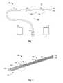
- FIG. 1is a schematic diagram of an ablation system in accordance with an embodiment of the present disclosure
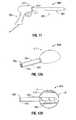
- FIG. 2is a partial, longitudinal cross-sectional view of an embodiment of the energy applicator of the ablation system shown in FIG. 1 in accordance with the present disclosure
- FIG. 3is an enlarged view of the indicated area of detail of FIG. 2 according to an embodiment of the present disclosure
- FIG. 4is a perspective view of an embodiment of a directional reflector assembly in accordance with the present disclosure
- FIG. 5is a partial, cross-sectional view of the energy applicator of FIG. 2 shown operably associated with the directional reflector assembly of FIG. 4 ;
- FIG. 6is a perspective view of another embodiment of a directional reflector assembly in accordance with the present disclosure.
- FIG. 7Ais a partial, perspective view of the energy applicator of FIG. 2 shown operably associated with the directional reflector assembly of FIG. 6 ;
- FIG. 7Bis a partial, perspective view of the energy applicator and directional reflector assembly of FIG. 7A shown with a fastener element coupled to an attachment portion of the directional reflector assembly;
- FIG. 8is a perspective view of an embodiment of a directional reflector assembly in accordance with the present disclosure that includes an adhesive-receiving recess;
- FIG. 9is a partial, cross-sectional view of the energy applicator of FIG. 2 shown operably associated with the directional reflector assembly of FIG. 8 ;
- FIG. 10is a cross-sectional view of the energy applicator of FIG. 2 shown operably associated with an embodiment of a directional reflector assembly in accordance with the present disclosure having a shell assembly including dielectric shells and an adhesive-receiving recess;
- FIG. 11is a perspective view of an embodiment of an energy applicator in accordance with the present disclosure that includes an ablation probe operably associated with a pistol-grip body and a male connector disposed at the proximal end of the probe;
- FIG. 12Ais a perspective view of an embodiment of a directional reflector assembly in accordance with the present disclosure that includes a tubular portion having a female connector adapted for attachment to the male connector of the energy applicator of FIG. 11 ;
- FIG. 12Bis a bottom, perspective view of the directional reflector assembly of FIG. 12A ;
- FIG. 13Ais a perspective view of the energy applicator of FIG. 11 shown with the directional reflector assembly of FIG. 12A mounted on the probe shaft thereof;
- FIG. 13Bis a bottom, perspective view of the energy applicator and the directional reflector assembly of FIG. 13A ;
- FIGS. 14A through 14Care perspective views of alternative embodiments of the directional reflector assembly of FIG. 12A ;
- FIG. 15is a side view of an ablation probe in accordance with the present disclosure having an alignment protrusion at a proximal end of a probe shaft thereof;
- FIG. 16is a side view of the ablation probe of FIG. 15 shown with a directional reflector assembly in accordance with the present disclosure mounted on the probe shaft;
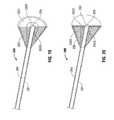
- FIG. 17is a perspective view of an embodiment of a directional reflector assembly in accordance with the present disclosure having an air-filled conical aperture
- FIG. 18is a perspective view of an embodiment of a directional reflector assembly in accordance with the present disclosure having a dielectric-filled conical aperture;
- FIG. 19is a perspective view of an embodiment of a directional reflector assembly in accordance with the present disclosure that includes a conical aperture having a plurality of dielectric layers;
- FIG. 20is a perspective view of an embodiment of a directional reflector assembly in accordance with the present disclosure that includes a conical aperture having a plurality of dielectric layers and an end cap;
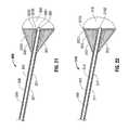
- FIG. 21is a perspective view of an embodiment of a directional reflector assembly in accordance with the present disclosure that includes a cooled shaft and a conical aperture having a plurality of dielectric layers;
- FIG. 22is a perspective view of an embodiment of a directional reflector assembly in accordance with the present disclosure that includes a cooled shaft and a conical aperture having fluid- and dielectric-filled regions;
- FIG. 23is a perspective view of an embodiment of a directional reflector assembly in accordance with the present disclosure that includes a cooled shaft and a coolant-filled conical aperture and an end cap;
- FIG. 24is a perspective view of an embodiment of a directional reflector assembly in accordance with the present disclosure that includes a conical aperture having fluid- and dielectric-filled regions;
- FIG. 25is a perspective view of an embodiment of a directional reflector assembly in accordance with the present disclosure that includes a dielectric-filled conical aperture and a balun positioned over the shaft;
- FIG. 26is a perspective view of an embodiment of a directional reflector assembly in accordance with the present disclosure that includes an air-filled conical aperture and a balun positioned over the shaft and within the cone;
- FIG. 27is a perspective view of an embodiment of a directional reflector assembly in accordance with the present disclosure that includes a dielectric-filled conical aperture and a balun positioned over the shaft and within the cone.
- proximalrefers to that portion of the apparatus that is closer to the user and the term “distal” refers to that portion of the apparatus that is farther from the user.
- Electromagnetic energyis generally classified by increasing energy or decreasing wavelength into radio waves, microwaves, infrared, visible light, ultraviolet, X-rays and gamma-rays.
- microwavegenerally refers to electromagnetic waves in the frequency range of 300 megahertz (MHz) (3 ⁇ 10 8 cycles/second) to 300 gigahertz (GHz) (3 ⁇ 10 11 cycles/second).
- ablation proceduregenerally refers to any ablation procedure, such as microwave ablation, radio frequency (RF) ablation or microwave ablation assisted resection.
- transmission linegenerally refers to any transmission medium that can be used for the propagation of signals from one point to another.
- Various embodiments of the present disclosureprovide electrosurgical devices operably associated with directional reflector assemblies for treating tissue and methods of directing electromagnetic radiation to a target volume of tissue.
- Embodimentsmay be implemented using electromagnetic radiation at microwave frequencies or at other frequencies.
- An electrosurgical system including an energy applicator operably associated with a directional reflector assembly, according to various embodiments,is designed and configured to operate between about 500 MHz and about 10 GHz with a directional radiation pattern.
- Various embodiments of the presently disclosed electrosurgical devices, directional reflector assemblies coupleable thereto and electrosurgical system including the sameare suitable for microwave ablation and for use to pre-coagulate tissue for microwave ablation assisted surgical resection.
- various methods described hereinbeloware targeted toward microwave ablation and the complete destruction of target tissue, it is to be understood that methods for directing electromagnetic radiation may be used with other therapies in which the target tissue is partially destroyed or damaged, such as, for example, to prevent the conduction of electrical impulses within heart tissue.
- the teachings of the present disclosuremay also apply to a monopole, helical, or other suitable type of microwave antenna.
- FIG. 1shows an electrosurgical system 10 , according to an embodiment of the present disclosure that includes an energy applicator or probe 100 .
- Probe 100generally includes an antenna assembly 12 having a radiating portion connected by a feedline 110 (or shaft) via a transmission line 15 to a connector 16 , which may further operably connect the probe 100 to an electrosurgical power generating source 28 , e.g., a microwave or RF electrosurgical generator.
- an electrosurgical power generating source 28e.g., a microwave or RF electrosurgical generator.
- Feedline 110may be formed from any suitable flexible, semi-rigid or rigid microwave conductive cable and may connect directly to an electrosurgical power generating source 28 . Alternatively, the feedline 110 may electrically connect the antenna assembly 12 via the transmission line 15 to the electrosurgical power generating source 28 . Feedline 110 may have a variable length from a proximal end of the antenna assembly 12 to a distal end of transmission line 15 ranging from a length of about one inch to about twelve inches. Feedline 110 may be formed of suitable electrically conductive materials, e.g., copper, gold, silver or other conductive metals having similar conductivity values. Feedline 110 may be made of stainless steel, which generally offers the strength required to puncture tissue and/or skin.
- Conductive materials used to form the feedline 110may be plated with other materials, e.g., other conductive materials, such as gold or silver, to improve their properties, e.g., to improve conductivity, decrease energy loss, etc.
- the feedline 110includes stainless steel, and to improve the conductivity thereof, the stainless steel may be coated with a layer of a conductive material such as copper or gold.
- Feedline 110may include an inner conductor, a dielectric material coaxially surrounding the inner conductor, and an outer conductor coaxially surrounding the dielectric material.
- Antenna assembly 12may be formed from a portion of the inner conductor that extends distal of the feedline 110 into the antenna assembly 12 .
- Feedline 110may be cooled by fluid e.g., saline or water, to improve power handling, and may include a stainless steel catheter.
- the power generating source 28is configured to provide microwave energy at an operational frequency from about 500 MHz to about 2500 MHz. In other embodiments, the power generating source 28 is configured to provide microwave energy at an operational frequency from about 500 MHz to about 10 GHz. Power generating source 28 may be configured to provide various frequencies of electromagnetic energy. Transmission line 15 may additionally, or alternatively, provide a conduit (not shown) configured to provide coolant from a coolant source 18 to the probe 100 .
- an end cap or tapered portion 120Located at the distal end of the antenna assembly 12 is an end cap or tapered portion 120 that may terminate in a sharp tip 123 to allow for insertion into tissue with minimal resistance.
- the end cap or tapered portion 120may include other shapes, such as, for example, a tip 123 that is rounded, flat, square, hexagonal, or cylindroconical.
- the antenna assembly 12includes a distal radiating portion 105 and a proximal radiating portion 140 .
- a junction member 130may be provided. Junction member 130 , or portions thereof, may be disposed between the proximal and distal radiating portions, 140 and 105 , respectively. In some embodiments, the distal and proximal radiating portions 105 , 140 align at the junction member 130 , which is generally made of a dielectric material, e.g., adhesives, and are also supported by the inner conductor that extends at least partially through the distal radiating portion 105 .
- Junction member 130may be formed from any suitable elastomeric or ceramic dielectric material by any suitable process.
- the junction member 130is formed by over-molding and includes a thermoplastic elastomer, such as, for example, polyether block amide (e.g., PEBAX®, manufactured by The Arkema Group of Colombes, France), polyetherimide (e.g., ULTEM® and/or EXTEM®, manufactured by SABIC Innovative Plastics of Saudi Arabia) and/or polyimide-based polymer (e.g., VESPEL®, manufactured by E. I. du Pont de Nemours and Company of Wilmington, Del., United States).
- Junction member 130may be formed using any suitable over-molding compound by any suitable process, and may include use of a ceramic substrate.
- the antenna assembly 12may be provided with a coolant chamber (not shown).
- the junction member 130may include coolant inflow and outflow ports (not shown) to facilitate the flow of coolant into, and out of, the coolant chamber. Examples of coolant chamber and coolant inflow and outflow port embodiments are disclosed in commonly assigned U.S. patent application Ser. No. 12/401,268 filed on Mar. 10, 2009, entitled “COOLED DIELECTRICALLY BUFFERED MICROWAVE DIPOLE ANTENNA”, and U.S. Pat. No. 7,311,703, entitled “DEVICES AND METHODS FOR COOLING MICROWAVE ANTENNAS”.
- the antenna assembly 12may be provided with an outer jacket (not shown) disposed about the distal radiating portion 105 , the junction 130 and/or the proximal radiating portion 140 .
- the outer jacketmay be formed of any suitable material, such as, for example, polymeric or ceramic materials.
- the outer jacketmay be applied by any suitable method, such as, for example, heat shrinking, over-molding, coating, spraying dipping, powder coating, baking and/or film deposition.
- the outer jacketmay be a water-cooled catheter formed of a material having low electrical conductivity.
- the probe 100is inserted into or placed adjacent to tissue and microwave energy is supplied thereto.
- Ultrasound or computed tomography (CT) guidancemay be used to accurately guide the probe 100 into the area of tissue to be treated.
- Probe 100may be placed percutaneously or surgically, e.g., using conventional surgical techniques by surgical staff.
- a clinicianmay pre-determine the length of time that microwave energy is to be applied.
- Application durationmay depend on many factors such as tumor size and location and whether the tumor was a secondary or primary cancer.
- the duration of microwave energy application using the probe 100may depend on the progress of the heat distribution within the tissue area that is to be destroyed and/or the surrounding tissue.
- Single or multiple probes 100may provide ablations in short procedure times, e.g., a few minutes, to destroy cancerous cells in the target tissue region.
- a plurality of probes 100may be placed in variously-arranged configurations to substantially simultaneously ablate a target tissue region, making faster procedures possible. Multiple probes 100 can be used to synergistically create a large ablation or to ablate separate sites simultaneously. Tissue ablation size and geometry is influenced by a variety of factors, such as the energy applicator design, number of energy applicators used simultaneously, time and wattage.
- microwave energy having a wavelength, lamda ( ⁇ )is transmitted through the antenna assembly 12 , e.g., along the proximal and distal radiating portions 140 , 105 , and radiated into the surrounding medium, e.g., tissue.
- the length of the antenna for efficient radiationmay be dependent on the effective wavelength ⁇ eff that is dependent upon the dielectric properties of the medium being radiated.
- Antenna assembly 12 through which microwave energy is transmitted at a wavelength ⁇may have differing effective wavelengths ⁇ eff depending upon the surrounding medium, e.g., liver tissue, as opposed to breast tissue.
- an embodiment of the antenna assembly 12 of FIG. 1includes an inner conductor 210 , an outer conductor 260 , and may include a first dielectric material 240 separating the inner conductor 210 and the outer conductor 260 .
- the inner conductor 210is formed from a first electrically conductive material (e.g., stainless steel) and the outer conductor 260 is formed from a second electrically conductive material (e.g., copper).
- the outer conductor 260coaxially surrounds the inner conductor 210 along a distal portion of the antenna assembly 12 , e.g., as shown in FIG. 2 .
- Inner conductor 210 and the outer conductor 260may be formed from any suitable electrically conductive material.
- First dielectric material 240may be formed from any suitable dielectric material. including, but not limited to, ceramics, water, mica, polyethylene, polyethylene terephthalate, polyimide, polytetrafluoroethylene (a.k.a. PTFE or Teflon®, manufactured by E. I. du Pont de Nemours and Company of Wilmington, Del., United States), glass, or metal oxides.
- Antenna assembly 12may be provided with a second dielectric material 29 surrounding the outer conductor 260 and/or the puck 130 , or portions thereof.
- Second dielectric material 29may be formed from any suitable dielectric material. In some embodiments, the second dielectric material 29 is formed from a material with a dielectric constant different than the dielectric constant of the first dielectric material 240 .
- the antenna assembly 12includes a conductor end portion 280 , which may be formed from any suitable electrically conductive material.
- the conductor end portion 280is coupled to the inner conductor 210 and may be formed of the same material as the inner conductor 210 . As shown in FIG. 2 , the conductor end portion 280 may be spaced apart from the outer conductor 260 by the puck 130 disposed therebetween. Tapered region 120 , or portions thereof, may surround a proximal portion of the conductor end portion 280 .
- the conductor end portion 280is substantially cylindrically shaped, and may be formed from stainless steel. The shape and size of the conductor end portion 280 may be varied from the configuration depicted in FIG. 2 . In some embodiments, at least a portion of the conductor end portion 280 is surrounded by the second dielectric material 29 .
- FIG. 4shows a directional reflector assembly 500 according to an embodiment of the present disclosure that includes a shell assembly 510 , a first attachment portion 520 disposed at the distal end portion 501 of the shell assembly 510 , and a second attachment portion 530 that extends proximally from the proximal end 502 of the shell assembly 510 .
- First attachment portion 520may have a substantially conical shape, and may be formed of any suitable material, such as metal.
- Second attachment portion 530may have a substantially cylindrical shape, and may be formed of any suitable material, such as a generally flexible and resilient thermoplastic material and/or metal.
- the second attachment portion 530may be replaceable (e.g., removeably coupleable to the shell assembly 510 , such as by a threaded fastener), thereby providing the capability to use second attachment portions 530 of different diameters to accommodate varied ablation probe diameters.
- Shell assembly 510may be shaped in such a manner to provide a desired surface ablation shape as well as aid in impedance matching.
- the shell assembly 510may taper from a diameter similar to the diameter of the second attachment portion 530 to a larger diameter as the shell assembly 510 extends proximally.
- Shell assembly 510may have any suitable shape and may be designed for tight spaces encountered during surgical operations.
- the shell assembly 510may have a shape similar to the shape of a thick butter knife (e.g., 921 shown in FIG. 14A ) or a half-conical shape (e.g., 931 shown in FIG. 14B ).
- the shell assembly 510generally includes an outer portion 511 and an inner portion 512 , and may include a recess in the form of a groove “G” defined in the planar surface “S” of the inner portion 512 generally configured to receive a portion of an energy applicator therein.
- a portion of the antenna assembly 12e.g., distal radiating portion 105 and proximal radiating portion 140 ) may be disposed within the groove “G” in the inner portion 512 .
- Outer portion 511may include an electrically conductive material, such as, for example, copper, stainless steel, titanium, titanium alloys such as nickel-titanium and titanium-aluminum-vanadium alloys, aluminum, aluminum alloys, tungsten carbide alloys or combinations thereof. Portions of the outer portion 511 may be loaded with low- to mid-range permittivity dielectric materials to aid in radiation directivity and impedance matching. In general, the dielectric permittivity would increase in value with radial distance from the electrically-conductive member 511 . Several shells, or other shapes, of different dielectric materials may nest together to form the outer portion 511 .
- Inner portion 512may include a dielectric material.
- the inner portion 512includes dielectric material layers.
- the inner portion 512may include one or more thin layers, one or more thick layers or a mixture of thick and thin layers.
- Inner portion 512may be composed of any suitable dielectric material which may be the same as, or different from, the dielectric material, if any, used in the outer portion 511 .
- the dielectric materials used to form the inner portion 512may vary in dielectric constant with shells (e.g., 7171 , 7172 and 7173 shown in FIG. 10 ) or more complex dielectric layering to achieve the optimum antenna directivity and energy to tissue delivery.
- the dielectric material used to form the inner portion 512may have a relatively high dielectric constant k (e.g., k ⁇ 80) to enhance the directional influence of the electromagnetic field.
- First and second attachment portions, 520 and 530may be formed of any suitable material, such as metal.
- the second attachment portion 530includes a tubular body 531 defining a lumen 534 into which a proximal portion of the antenna assembly 12 may be positioned.
- Tubular body 531may be provided with an inner liner (not shown) disposed in contact with the inner surface 535 , or portion thereof, of the lumen 534 , wherein the inner liner is configured to frictionally engage at least a portion of the outer surface of an energy applicator shaft disposed within the lumen 534 when the directional reflector assembly 500 is operably associated with the energy applicator.
- An outer sleevemay additionally, or alternatively, be provided to at least a portion of an energy applicator, wherein the outer sleeve is adapted to frictionally engage the inner surface 535 of the lumen 534 .
- the second attachment portion 530or portion thereof, is formed of a generally flexible and/or resilient material, e.g., silicon rubber, and may be provided with a fastener element (e.g., 660 shown in FIG. 7B ) disposed around the outer surface thereof, e.g., for releaseably securing a proximal portion of an energy applicator disposed within the lumen 534 .
- First attachment portion 520generally includes a body 521 defining a chamber 524 therein and an opening in communication with the groove “G”. Opening 523 and the chamber 524 are generally configured to receive the distal end portion of an energy applicator, e.g., tip 123 of the antenna assembly 12 .
- the shape and size of the first and second attachment portions, 520 and 530may be varied from the configuration depicted in FIG. 4 .
- FIG. 6shows a directional reflector assembly 600 according to an embodiment of the present disclosure that includes a shell assembly 610 , a first attachment portion 620 , and a second attachment portion 640 .
- Shell assembly 610generally includes an outer portion 611 and an inner portion 612 , and may include a recess in the form of a groove “G” defined in the planar surface “S” of the inner portion 612 generally configured to receive a portion of an energy applicator therein.
- Shell assembly 610is similar to the shell assembly 510 shown in FIG. 4 , and further description thereof is omitted in the interests of brevity.
- First attachment portion 620generally includes a body 621 defining a chamber 624 therein and an opening in communication with the groove “G” defined in the inner portion 612 .
- First attachment portion 620is similar to the first attachment portion 520 shown in FIG. 4 , and further description thereof is omitted in the interests of brevity.
- Second attachment portion 640extends proximally from the proximal end of the shell assembly 610 .
- Second attachment portion 640is similar to the second attachment portion 530 shown in FIG. 4 , except for its shape.
- the second attachment portion 640includes a body 641 having a partial, cylindrical shape (e.g., a partial cylinder with a substantially C-shaped cross section) of any suitable length.
- Second attachment portion 640may be formed of any suitable rigid, semi-rigid or flexible material, including, but not limited to, rubber, metal, polymeric materials, and combinations thereof.
- FIG. 7Ashows the antenna assembly 12 of FIG. 2 operably associated with the directional reflector assembly 600 of FIG. 6 .
- the second attachment portion 640may be provided with a fastener element 660 generally adapted for releaseably closing the partial, cylindrically-shaped fastener element 660 around a proximal portion of the antenna assembly 12 .
- Fastener element 660may include any suitable fastener, such any suitable releasable fastener, coupleable to at least a portion of the outer surface of the second attachment portion 640 .
- the fastener element 660may include adhesive tape, wire, plastic tie cinch straps or other suitable tongue and groove type elongated flexible plastic fasteners, metal clips, plastic clips, fabric or plastic straps, VELCROTM hook and loop brand type tapes, etc.
- FIG. 8shows a directional reflector assembly 700 according to an embodiment of the present disclosure that includes a shell assembly 710 .
- Shell assembly 710generally includes an outer portion 711 and an inner portion 717 , and may include a recess in the form of a groove “G” defined in the planar surface “S” of the inner portion 717 .
- Outer portion 711is similar to the outer portion 511 shown in FIG. 4 , and further description thereof is omitted in the interests of brevity.
- Groove “G”is generally configured to receive a portion of an energy applicator therein.
- the groove “G”includes an adhesive-receiving recess 736 for receiving an adhesive material (e.g., “A” shown in FIG. 10 ) therein.
- Recess 736may be any suitable shape, and may extend along the longitudinal axis of the groove “G”. In embodiments, the length, depth and/or volume of the recess 736 may vary, e.g., depending on the material properties of the adhesive material “A” to be provided therein.
- the recess 736may be single, elongated recess or a plurality of recesses.
- FIGS. 9 and 10show the antenna assembly 12 of FIG. 2 operably associated with the directional reflector assembly 700 of FIG. 8 .
- the inner portion 717 of the shell assembly 710may be formed of a first dielectric layer 7171 , a second dielectric layer 7172 and a third dielectric layer 7173 .
- Inner portion 717may include any suitable number of dielectric layers in varied configurations.
- a variety of dielectric materialsmay suitably be used, including, but not limited to, polymers, ceramics, metal oxides and combinations thereof.
- the dielectric material used to form the third dielectric layer 7173may have a relatively low dielectric constant k, such as k ⁇ 4.
- the thicknesses and dielectric constant k of the first, second and third dielectric layers, 7171 , 7172 and 7173 , respectively,may be optimized, e.g., based on the desired frequency and desired field pattern, to ablate an area of tissue to the desired depth.
- FIG. 11is a perspective view of an embodiment of an energy applicator 800 in accordance with the present disclosure that includes a pistol-grip body 850 , a probe 860 extending distally therefrom., and a male connector 812 disposed at the proximal end of the ablation probe 860 .
- Pistol-grip body 850is operably associated with the male connector 812 .
- the male connector 812includes a retainer member 811 that is movable between at least an engagement position and a released position.
- the pistol-grip body 850may include a user operable switch 815 , e.g., a push button, operable to move the male connector 812 from an engagement position, in which the retainer member 811 is engaged with a female connector (e.g., 916 shown in FIGS. 12 A and 14 A- 14 C), to a released position, in which the retainer member 811 is disengaged from the female connector.
- a user operable switch 815e.g., a push button
- the shape and size of the male connector 812may be varied from the configuration depicted in FIG. 11 .
- FIGS. 12A and 12Bshow an embodiment of a directional reflector assembly 910 in accordance with the present disclosure that includes a shell assembly 917 , a tubular portion 925 defining a lumen 934 , and a female connector 916 associated with the proximal end 905 of the tubular portion 930 .
- Female connector 916is adapted for engagement with the male connector 812 of the energy applicator 800 of FIG. 11 .
- Shell assembly 917generally includes an outer portion 911 and an inner portion 912 , and may include a recess 919 defined in the planar surface “S” of the inner portion 912 generally configured to receive a distal end portion of an energy applicator therein.
- Shell assembly 917is similar to the shell assembly 710 shown in FIG. 8 , and further description thereof is omitted in the interests of brevity.
- FIGS. 13A and 13Bshow the energy applicator of FIG. 11 with the directional reflector assembly of FIG. 12A mounted thereupon.
- the lumen 934is configured to receive the ablation probe 860 , whereby the distal portion 861 of the ablation probe 860 extends across the planar surface “S” of the shell assembly 911 .
- FIG. 14Ashows an embodiment of a directional reflector assembly 920 in accordance with the present disclosure that includes a shell assembly 927 , a tubular portion 925 defining a lumen 934 , and a female connector 916 associated with the proximal end 905 of the tubular portion 925 .
- the shell assembly 927has a paddle-like or thick butter knife shape, and may include a recess 929 defined in a planar surface “S” thereof.
- Shell assembly 927is similar to the shell assembly 917 shown in FIG. 12A , except for its shape, and further description thereof is omitted in the interests of brevity.
- FIG. 14Bshows an embodiment of a directional reflector assembly 930 in accordance with the present disclosure that includes a shell assembly 937 , a tubular portion 925 defining a lumen 934 , and a female connector 916 associated with the proximal end 905 of the tubular portion 925 .
- the shell assembly 937has a half-conical shape, and may include a recess 939 defined in a planar surface “S” thereof.
- Shell assembly 937is similar to the shell assembly 917 shown in FIG. 12A , except for its shape, and further description thereof is omitted in the interests of brevity.
- FIG. 14Cshows an embodiment of a directional reflector assembly 940 in accordance with the present disclosure that includes a shell assembly 947 , a tubular portion 925 defining a lumen 934 , and a female connector 916 associated with the proximal end 905 of the tubular portion 925 .
- the shell assembly 947has a partial, cylindrical shape, and may include a recess 949 defined in a planar surface “S” thereof.
- Shell assembly 947is similar to the shell assembly 917 shown in FIG. 12A , except for its shape, and further description thereof is omitted in the interests of brevity.
- microwave ablation probe 400includes a handle 410 fixed at a distal end thereof to a shaft 420 having a tip 422 .
- a cable 415couples the probe 400 to a source of microwave ablation energy (not shown).
- a directional reflector assembly 405includes a tubular shaft 440 and a conical aperture 442 .
- Shaft 440includes a coupling 425 having one or more slots 445 defined therein that are adapted to engage a protrusion 430 provided at a proximal end 421 of a probe shaft 420 .
- slot 445 with protrusion 430may aid the positioning of outer tube 440 with probe shaft 420 , and may additionally, or alternatively, provide positive retention of outer tube 440 to probe shaft 420 during use.
- Slot 445 and protrusion 430may include a bayonet arrangement, as shown, and may additionally or alternative include any suitable coupling arrangement, such as without limitation, a threaded arrangement, an interference fit arrangement, or other coupling arrangement.
- Coupling 425may additionally, or alternatively, be configured to provide coolant coupling (e.g., fluid or gas coupling) between the probe handle 410 and/or shaft 420 , and a directional reflector assembly.
- FIG. 17shows an embodiment of an air-filled directional reflector assembly 260 that includes an outer tube 261 having a distal end 264 and a proximal end 265 that is dimensioned to slideably engage a probe shaft (e.g., 420 ).
- Outer tube 261may be formed from any suitable material, including without limitation metallic material (e.g., stainless steel) and/or dielectric material (e.g., epoxy fiber composite).
- a conical aperture 262 having a distal base opening 263 and a proximal apex opening 265is joined at a proximal apex opening 265 thereof to a distal end 264 of shaft 261 .
- the directional reflector assembly 260is positioned onto a recipient microwave ablation probe (not shown) by sliding a distal end of the probe into a proximal inner portion 266 of outer tube 261 .
- a generally circular distal plate (not shown) having a circular opening disposed at a center thereofis fixed at a perimeter thereof to a distal open base of conical aperture 262 .
- Directional reflector assembly 270includes an outer tube 271 having a distal end 276 and a proximal end 277 that is dimensioned to slideably engage a probe shaft as previously described herein.
- Outer tube 271may be formed from any suitable material, as previously described herein.
- a conical reflector 272having a distal base opening 273 and a proximal apex opening 278 is joined at the proximal apex opening 278 to a distal end 276 of shaft 271 .
- Conical reflector 272includes a dielectric core 279 disposed therein.
- An inner opening 274 defined within outer tube 271is coupled to an inner opening 275 axially defined within dielectric core 279 .
- An inner diameter of outer tube 271(e.g., corresponding to the diameter of inner opening 274 ) is substantially equal to an inner diameter of inner opening 275 to form a substantially continuous opening 274 between tube 271 and a distal end of dielectric core 279 to accommodate the insertion of an ablation probe thereinto for use, as previously described herein.
- a multilayer dielectric-filled directional reflector assembly 280includes an outer tube 281 having an inner opening 284 defined longitudinally therein.
- a conical reflector 282is joined at a proximal open apex end thereof to a distal end of outer tube 281 .
- Conical reflector 282includes at least a first dielectric core region 2831 , that may be formed from a first dielectric material, and a second dielectric core region 2832 , that may be formed from a second dielectric material. Additional dielectric core regions beyond a first and second are envisioned within the scope of the present disclosure, e.g., dielectric core region 2833 .
- the dielectric core regions 2831et seq.
- the dielectric core regionsmay have other shapes and arrangement, including but not limited to, planar, interleaved, toroidal, radial, cylindrical, and polygonal extrusions.
- An inner opening 284 defined within outer tube 281is coupled to an inner opening 285 axially defined through the innermost multilayer dielectric core region, e.g., 2833 .
- An inner diameter of outer tube 281(e.g., corresponding to the diameter of inner opening 284 ) is substantially equal to an inner diameter of inner opening 285 to form a substantially continuous opening 284 between tube 281 and a distal end of multilayer dielectric core 2831 et seq. to accommodate the insertion of an ablation probe therein for use, as previously described herein.
- a multilayer dielectric-filled directional reflector assembly 290includes a tubular shaft 291 having an inner opening 294 defined longitudinally therein.
- a conical reflector 292is joined at a proximal open apex end thereof to a distal end of tubular shaft 291 .
- a generally circular distal plate 298 having a circular opening 299 disposed at a center thereofis fixed at a perimeter thereof to a distal open base of reflector 292 .
- Circular distal plate 298may be formed from material that is radiofrequency transparent at an operating frequency of a microwave ablation probe, which may be in a range of about 915 MHz to about 2.45 GHz.
- Circular distal plate 298may additionally, or alternatively, be formed from a lubricious material, including without limitation, polytetrafluoroethylene (a.k.a. PTFE or Teflon®, manufactured by the E.I. du Pont de Nemours and Company of Wilmington, Del., United States).
- a lubricious materialincluding without limitation, polytetrafluoroethylene (a.k.a. PTFE or Teflon®, manufactured by the E.I. du Pont de Nemours and Company of Wilmington, Del., United States).
- Conical reflector 292includes one or more dielectric core regions, e.g., 2931 , 2932 , 2933 .
- the dielectric core regions 2931 , 2932 , 2933 et seq.may be formed from similar, or from dissimilar, dielectric materials.
- the dielectric core regions 2931 et seq.may have a flared conical shape and may be arranged coaxially, radially, or may have other shapes and arrangements, including but not limited to, planar, interleaved, toroidal, cylindrical, and polygonal extrusions.
- a longitudinal inner opening 294 defined within tubular shaft 291is coupled to an inner opening 295 axially defined through an innermost dielectric core region, e.g., 2933 .
- An inner diameter of tubular shaft 291(e.g., corresponding to the diameter of inner opening 294 ) may be substantially equal to an inner diameter of inner opening 295 and to circular opening 299 to form a substantially continuous opening 294 between tube 291 and a distal surface of circular distal plate 298 to accommodate the insertion of an ablation probe therein for use, as previously described herein.
- FIG. 21illustrates yet another embodiment wherein a directional reflector assembly 300 includes a dual-wall cooled shaft 301 .
- the cooled shaft 301includes an inner tube 309 coaxially disposed within an outer tube 308 having a cooling region 307 disposed therebetween.
- Cooling region 307may include thermally-conductive material (e.g., copper) and/or heat pipe that is adapted to transfer thermal energy from the shaft 301 and/or a conical reflector 302 by conduction or convection.
- Cooling region 307may additionally, or alternatively, include fluid coolant. Examples of coolant include, but are not limited to, liquids such as deionized water, or saline.
- Cooling regionmay extend distally into conical reflector 302 along a channel 305 defined between an outer surface of inner tube 309 and an inner surface of an innermost dielectric core region, e.g., 3033 .
- a generally circular distal plate 306 having a circular opening 3061 disposed at a center thereofis fixed at a perimeter thereof to a distal open base of reflector 302 .
- Circular distal plate 306may be formed from material that is radiofrequency transparent and/or lubricious as previously described herein.
- Conical reflector 302may include one or more dielectric core regions, e.g., 3031 , 3032 , 3033 et seq.
- Inner tube 309extends distally into conical reflector 302 to form a continuous opening 304 defined axially within the directional reflector assembly 300 , e.g., from a proximal end of shaft 301 to a distal surface of cover 306 to accommodate the insertion of an ablation probe therein for use, as previously described.
- a fluid-cooled directional reflector assembly 310includes a dual-wall cooled shaft 311 having an outer tube 318 , an inner tube 317 coaxially disposed therein and defining an opening 314 , and a fluid path 319 defined therebetween.
- a conical aperture 312is joined to a distal end of the outer tube 318 .
- Conical aperture 312includes a dielectric 313 disposed therein.
- a cooling chamber 315having a proximal end in fluid communication with a distal end of fluid path 319 is defined within the dielectric 313 .
- a generally circular distal plate 316 having a circular opening 3162 defined at a center thereofis fixed at least at a perimeter 3161 thereof to a distal rim 3121 of an open base of reflector 312 and adapted to form a sealed distal end of cooling chamber 315 .
- Circular distal plate 316may additionally, or alternatively, be joined at the center thereof to an outer surface and/or distal end of inner tube 317 .
- coolantmay circulate through fluid path 319 and or cooling chamber 315 , which may help control the temperature of the attachment 310 , and may provide dielectric loading within the aperture 312 .
- Circular distal plate 316may be formed from fluid-impermeable material that is radiofrequency transparent and/or lubricious, such as without limitation, PTFE.
- a fluid-cooled directional reflector assembly 320may include a conical aperture 322 having a cooling chamber 325 defined therein by the interior volume of the aperture 322 and a circular distal plate 326 .
- Circular distal plate 326is fixed at an outer perimeter 3261 thereof to a distal rim 3221 of conical aperture 322 .
- Circular distal plate 326may additionally, or alternatively, be fixed at a perimeter of an opening 3262 define therein to a distal outer surface of inner tube 327 .
- FIG. 24depicts a fluid-cooled directional reflector assembly 330 having a single-walled tubular shaft 331 defining an opening 334 therein and joined at a distal end thereof to a proximal open apex 333 of conical aperture 332 .
- a circular distal plate 336fixed at an outer perimeter 338 thereof to a distal rim 335 of conical aperture 322 to define a coolant chamber 339 within the conical aperture 322 .
- Circular distal plate 336additionally, or alternatively, includes an opening 337 defined therein that is joined at a perimeter thereof to a distal outer surface of tubular shaft 331 .
- Coolant chamber 339contains coolant 3391 , for example, and without limitation, saline, sterile water, and/or deionized water, which may enhance cooling and/or improved dielectric loading during use.
- a directional reflector assembly in accordance with the present disclosuremay include one or more baluns, which may improve the radiation and/or ablation pattern provided during use. More particularly, and with reference now to FIG. 25 , a directional reflector assembly 340 includes a tubular shaft 341 defining an opening 344 therein and joined at a distal end thereof to a proximal open apex 343 of a conical aperture 342 . A circular distal plate 346 is disposed at a distal open end of the conical aperture 342 in a manner previously described herein. A dielectric core 347 is disposed within the conical aperture 342 .
- a balun 345is concentrically disposed around at least a part of tubular shaft 341 , e.g., along a distal portion of the shaft 341 and substantially adjacent to the proximal open apex 343 of the conical aperture 342 .
- Balun 345may include a ring-like balun short 349 concentrically disposed around the shaft 341 at a proximal end of the balun 345 and electrically coupled thereto.
- a balun dielectric layer 348may additionally, or alternatively, be concentrically disposed between the balun 345 and the shaft 341 .
- an air-filled directional reflector assembly 350includes a tubular shaft 351 defining an opening 354 therein and joined at a distal end thereof to a proximal open apex 357 of a conical aperture 352 .
- a first balun 355is concentrically disposed around at least a part of tubular shaft 351 , e.g., along a distal portion of the shaft 351 and substantially adjacent to the proximal open apex 357 of the conical aperture 352 .
- First balun 355may include a ring-like balun short 359 concentrically disposed around the shaft 351 at a proximal end of the balun 355 and electrically coupled thereto.
- a first balun dielectric layer 358may additionally, or alternatively, be concentrically disposed between the balun 355 and the shaft 351 .
- Conical aperture 352includes a second balun dielectric layer 353 disposed between an inner surface of conical aperture 352 and a second balun 356 .
- First balun 355 and second balun 356may be electrically coupled.
- FIG. 27illustrates still another embodiment in accordance with the present disclosure that may include a shaft balun, a cone balun, and/or a dielectric core.
- a dielectric core directional reflector assembly 360includes a tubular shaft 361 that is joined at a distal end thereof to a proximal open apex 370 of a conical aperture 362 .
- a first balun 365is concentrically disposed around at least a part of tubular shaft 361 , e.g., along a distal portion of the shaft 361 and substantially adjacent to the proximal open apex 370 of conical aperture 362 .
- First balun 365may include a ring-like balun short 369 concentrically disposed around the shaft 361 at a proximal end of the balun 365 and electrically coupled thereto.
- a first balun dielectric layer 368may additionally, or alternatively, be concentrically disposed between the balun 365 and the shaft 361 .
- Conical aperture 362includes a second balun dielectric layer 363 disposed between an inner surface of conical aperture 362 and a second balun 366 .
- First balun 365 and second balun 366may be electrically coupled.
- Conical reflector 362includes a dielectric core 367 disposed therein, e.g., within an inner surface of second balun 366 .
- An inner opening 364 defined within outer shaft 361is coupled to an inner opening 371 axially defined within dielectric core 367 .
- An inner diameter of outer shaft 361(e.g., the diameter of inner opening 364 ) is substantially equal to an inner diameter of inner opening 371 to form a substantially continuous opening 364 between a proximal end of outer shaft 361 and a distal end of dielectric core 361 to accommodate the insertion of an ablation probe thereinto for use, as previously described herein.
- the above-described directional reflector assemblies and electrosurgical devices for treating tissue and methods of directing electromagnetic radiation to a target volume of tissuemay be used to provide directional microwave ablation, wherein the heating zone may be focused to one side of the electrosurgical device, thereby allowing clinicians to target small and/or hard tumors without having to penetrate the tumor directly or effect more healthy tissue than necessary.
- the presently disclosed electrosurgical devices and directional reflector assembliesmay allow clinicians to avoid ablating critical structures, such as large vessels, healthy organs or vital membrane barriers, by placing the electrosurgical device between the tumor and critical structure and directing the electromagnetic radiation toward the tumor and away from the sensitive structure.
Landscapes
- Health & Medical Sciences (AREA)
- Surgery (AREA)
- Life Sciences & Earth Sciences (AREA)
- Heart & Thoracic Surgery (AREA)
- Molecular Biology (AREA)
- Veterinary Medicine (AREA)
- Engineering & Computer Science (AREA)
- Biomedical Technology (AREA)
- Nuclear Medicine, Radiotherapy & Molecular Imaging (AREA)
- Medical Informatics (AREA)
- Public Health (AREA)
- Animal Behavior & Ethology (AREA)
- General Health & Medical Sciences (AREA)
- Physics & Mathematics (AREA)
- Electromagnetism (AREA)
- Otolaryngology (AREA)
- Pathology (AREA)
- Oral & Maxillofacial Surgery (AREA)
- Surgical Instruments (AREA)
Abstract
Description
Claims (4)
Priority Applications (5)
| Application Number | Priority Date | Filing Date | Title |
|---|---|---|---|
| US12/568,524US8906007B2 (en) | 2009-09-28 | 2009-09-28 | Electrosurgical devices, directional reflector assemblies coupleable thereto, and electrosurgical systems including same |
| EP10010942.0AEP2377481B1 (en) | 2009-09-28 | 2010-09-27 | Directional reflector assembly |
| JP2010214756AJP5657974B2 (en) | 2009-09-28 | 2010-09-27 | Electrosurgical apparatus, directional reflector assembly connectable thereto, and electrosurgical system comprising them |
| US14/564,946US9622816B2 (en) | 2009-09-28 | 2014-12-09 | Electrosurgical devices, directional reflector assemblies coupleable thereto, and electrosurgical systems including same |
| US15/477,308US20170202618A1 (en) | 2009-09-28 | 2017-04-03 | Electrosurgical devices, directional reflector assemblies coupleable thereto, and electrosurgical systems including same |
Applications Claiming Priority (1)
| Application Number | Priority Date | Filing Date | Title |
|---|---|---|---|
| US12/568,524US8906007B2 (en) | 2009-09-28 | 2009-09-28 | Electrosurgical devices, directional reflector assemblies coupleable thereto, and electrosurgical systems including same |
Related Child Applications (1)
| Application Number | Title | Priority Date | Filing Date |
|---|---|---|---|
| US14/564,946ContinuationUS9622816B2 (en) | 2009-09-28 | 2014-12-09 | Electrosurgical devices, directional reflector assemblies coupleable thereto, and electrosurgical systems including same |
Publications (2)
| Publication Number | Publication Date |
|---|---|
| US20110077633A1 US20110077633A1 (en) | 2011-03-31 |
| US8906007B2true US8906007B2 (en) | 2014-12-09 |
Family
ID=43533392
Family Applications (3)
| Application Number | Title | Priority Date | Filing Date |
|---|---|---|---|
| US12/568,524Active2031-12-12US8906007B2 (en) | 2009-09-28 | 2009-09-28 | Electrosurgical devices, directional reflector assemblies coupleable thereto, and electrosurgical systems including same |
| US14/564,946Expired - Fee RelatedUS9622816B2 (en) | 2009-09-28 | 2014-12-09 | Electrosurgical devices, directional reflector assemblies coupleable thereto, and electrosurgical systems including same |
| US15/477,308AbandonedUS20170202618A1 (en) | 2009-09-28 | 2017-04-03 | Electrosurgical devices, directional reflector assemblies coupleable thereto, and electrosurgical systems including same |
Family Applications After (2)
| Application Number | Title | Priority Date | Filing Date |
|---|---|---|---|
| US14/564,946Expired - Fee RelatedUS9622816B2 (en) | 2009-09-28 | 2014-12-09 | Electrosurgical devices, directional reflector assemblies coupleable thereto, and electrosurgical systems including same |
| US15/477,308AbandonedUS20170202618A1 (en) | 2009-09-28 | 2017-04-03 | Electrosurgical devices, directional reflector assemblies coupleable thereto, and electrosurgical systems including same |
Country Status (3)
| Country | Link |
|---|---|
| US (3) | US8906007B2 (en) |
| EP (1) | EP2377481B1 (en) |
| JP (1) | JP5657974B2 (en) |
Cited By (19)
| Publication number | Priority date | Publication date | Assignee | Title |
|---|---|---|---|---|
| US20150045785A1 (en)* | 2011-12-14 | 2015-02-12 | Emblation Limited | Microwave applicator and method of forming a microwave applicator |
| US9241762B2 (en) | 2010-06-03 | 2016-01-26 | Covidien Lp | Specific absorption rate measurement and energy-delivery device characterization using image analysis |
| US9375278B2 (en) | 2009-09-18 | 2016-06-28 | Covidien Lp | Tissue ablation system with energy distribution |
| US9622816B2 (en) | 2009-09-28 | 2017-04-18 | Covidien Lp | Electrosurgical devices, directional reflector assemblies coupleable thereto, and electrosurgical systems including same |
| US10028787B2 (en) | 2010-02-26 | 2018-07-24 | Covidien Lp | Tunable microwave ablation probe |
| US10213256B2 (en) | 2009-10-28 | 2019-02-26 | Covidien Lp | System and method for monitoring ablation size |
| US10251701B2 (en) | 2010-05-25 | 2019-04-09 | Covidien Lp | Flow rate verification monitor for fluid-cooled microwave ablation probe |
| US10327845B2 (en) | 2010-01-25 | 2019-06-25 | Covidien Lp | System and method for monitoring ablation size |
| US10390882B2 (en) | 2009-09-29 | 2019-08-27 | Covidien Lp | Flow rate monitor for fluid cooled microwave ablation probe |
| US10588684B2 (en) | 2010-07-19 | 2020-03-17 | Covidien Lp | Hydraulic conductivity monitoring to initiate tissue division |
| US10772492B2 (en)* | 2005-02-02 | 2020-09-15 | Intuitive Surgical Operations, Inc. | Methods and apparatus for efficient purging |
| US10987152B2 (en) | 2010-02-19 | 2021-04-27 | Covidien Lp | Ablation devices with dual operating frequencies, systems including same, and methods of adjusting ablation volume using same |
| US11337594B2 (en) | 2006-09-01 | 2022-05-24 | Intuitive Surgical Operations, Inc. | Coronary sinus cannulation |
| US11406250B2 (en) | 2005-02-02 | 2022-08-09 | Intuitive Surgical Operations, Inc. | Methods and apparatus for treatment of atrial fibrillation |
| US11478152B2 (en) | 2005-02-02 | 2022-10-25 | Intuitive Surgical Operations, Inc. | Electrophysiology mapping and visualization system |
| US11559188B2 (en) | 2006-12-21 | 2023-01-24 | Intuitive Surgical Operations, Inc. | Off-axis visualization systems |
| US11779195B2 (en) | 2006-09-01 | 2023-10-10 | Intuitive Surgical Operations, Inc. | Precision control systems for tissue visualization and manipulation assemblies |
| US11882996B2 (en) | 2006-06-14 | 2024-01-30 | Intuitive Surgical Operations, Inc. | In-vivo visualization systems |
| US12408824B2 (en) | 2005-02-02 | 2025-09-09 | Intuitive Surgical Operations, Inc. | Tissue visualization and manipulation system |
Families Citing this family (34)
| Publication number | Priority date | Publication date | Assignee | Title |
|---|---|---|---|---|
| US7553309B2 (en) | 2004-10-08 | 2009-06-30 | Covidien Ag | Electrosurgical system employing multiple electrodes and method thereof |
| US8292881B2 (en) | 2009-05-27 | 2012-10-23 | Vivant Medical, Inc. | Narrow gauge high strength choked wet tip microwave ablation antenna |
| US8323275B2 (en) | 2009-06-19 | 2012-12-04 | Vivant Medical, Inc. | Laparoscopic port with microwave rectifier |
| US8328799B2 (en) | 2009-08-05 | 2012-12-11 | Vivant Medical, Inc. | Electrosurgical devices having dielectric loaded coaxial aperture with distally positioned resonant structure |
| US8328801B2 (en) | 2009-08-17 | 2012-12-11 | Vivant Medical, Inc. | Surface ablation antenna with dielectric loading |
| US9113925B2 (en)* | 2009-09-09 | 2015-08-25 | Covidien Lp | System and method for performing an ablation procedure |
| US8069553B2 (en) | 2009-09-09 | 2011-12-06 | Vivant Medical, Inc. | Method for constructing a dipole antenna |
| US8568401B2 (en) | 2009-10-27 | 2013-10-29 | Covidien Lp | System for monitoring ablation size |
| US8382750B2 (en)* | 2009-10-28 | 2013-02-26 | Vivant Medical, Inc. | System and method for monitoring ablation size |
| US8394092B2 (en)* | 2009-11-17 | 2013-03-12 | Vivant Medical, Inc. | Electromagnetic energy delivery devices including an energy applicator array and electrosurgical systems including same |
| US8491579B2 (en) | 2010-02-05 | 2013-07-23 | Covidien Lp | Electrosurgical devices with choke shorted to biological tissue |
| US8728067B2 (en) | 2010-03-08 | 2014-05-20 | Covidien Lp | Microwave antenna probe having a deployable ground plane |
| US9028474B2 (en) | 2010-03-25 | 2015-05-12 | Covidien Lp | Microwave surface coagulator with retractable blade |
| US8409188B2 (en) | 2010-03-26 | 2013-04-02 | Covidien Lp | Ablation devices with adjustable radiating section lengths, electrosurgical systems including same, and methods of adjusting ablation fields using same |
| US10039601B2 (en) | 2010-03-26 | 2018-08-07 | Covidien Lp | Ablation devices with adjustable radiating section lengths, electrosurgical systems including same, and methods of adjusting ablation fields using same |
| US8652127B2 (en) | 2010-05-26 | 2014-02-18 | Covidien Lp | System and method for chemically cooling an ablation antenna |
| US8672933B2 (en) | 2010-06-30 | 2014-03-18 | Covidien Lp | Microwave antenna having a reactively-loaded loop configuration |
| US9028476B2 (en) | 2011-02-03 | 2015-05-12 | Covidien Lp | Dual antenna microwave resection and ablation device, system and method of use |
| US9198724B2 (en)* | 2011-04-08 | 2015-12-01 | Covidien Lp | Microwave tissue dissection and coagulation |
| US9579150B2 (en) | 2011-04-08 | 2017-02-28 | Covidien Lp | Microwave ablation instrument with interchangeable antenna probe |
| US9113930B2 (en) | 2012-01-05 | 2015-08-25 | Covidien Lp | Ablation systems, probes, and methods for reducing radiation from an ablation probe into the environment |
| CN102697557B (en)* | 2012-06-06 | 2014-12-31 | 王建新 | Cervical microwave thermotherapy radiator |
| US9332959B2 (en)* | 2012-06-26 | 2016-05-10 | Covidien Lp | Methods and systems for enhancing ultrasonic visibility of energy-delivery devices within tissue |
| DE102013101407A1 (en)* | 2013-02-13 | 2014-08-14 | Khs Gmbh | Process for packaging liquid products under pressure in bottles of plastic or similar containers |
| US10076384B2 (en)* | 2013-03-08 | 2018-09-18 | Symple Surgical, Inc. | Balloon catheter apparatus with microwave emitter |
| US10092746B2 (en)* | 2014-03-06 | 2018-10-09 | Biotronik Se & Co. Kg | Implantable device |
| US10186780B2 (en) | 2014-05-05 | 2019-01-22 | Per Olov Risman | Microwave antenna applicator |
| US10624697B2 (en)* | 2014-08-26 | 2020-04-21 | Covidien Lp | Microwave ablation system |
| US11419677B2 (en) | 2014-12-02 | 2022-08-23 | Kansas State University Research Foundation | High-efficiency, directional microwave ablation antenna |
| US20180325413A1 (en) | 2015-11-09 | 2018-11-15 | Opr Mikrovågsteknik Ekonomisk Förening | Quantification of inhomogeneities in objects by electromagnetic fields |
| US10856940B2 (en)* | 2016-03-02 | 2020-12-08 | Covidien Lp | Ablation antenna including customizable reflectors |
| GB2565575A (en)* | 2017-08-17 | 2019-02-20 | Creo Medical Ltd | Electrosurgical apparatus for delivering RF and/or microwave energy into biological tissue |
| US20190201093A1 (en)* | 2018-01-03 | 2019-07-04 | Neuwave Medical, Inc. | Systems and methods for energy delivery |
| US11304755B2 (en)* | 2018-04-18 | 2022-04-19 | Boston Scientific Scimed, Inc. | Microwave tissue ablation probe with non-metallic introducer set |
Citations (103)
| Publication number | Priority date | Publication date | Assignee | Title |
|---|---|---|---|---|
| SU166452A1 (en) | В. А. Костров , Л. В. Смирнов | STOMATOLOGICAL DIATHERMOKOAGULATOR | ||
| DE390937C (en) | 1922-10-13 | 1924-03-03 | Adolf Erb | Device for internal heating of furnace furnaces for hardening, tempering, annealing, quenching and melting |
| DE1099658B (en) | 1959-04-29 | 1961-02-16 | Siemens Reiniger Werke Ag | Automatic switch-on device for high-frequency surgical devices |
| FR1275415A (en) | 1960-09-26 | 1961-11-10 | Device for detecting disturbances for electrical installations, in particular electrosurgery | |
| DE1139927B (en) | 1961-01-03 | 1962-11-22 | Friedrich Laber | High-frequency surgical device |
| DE1149832B (en) | 1961-02-25 | 1963-06-06 | Siemens Reiniger Werke Ag | High frequency surgical apparatus |
| FR1347865A (en) | 1962-11-22 | 1964-01-04 | Improvements to diathermo-coagulation devices | |
| DE1439302A1 (en) | 1963-10-26 | 1969-01-23 | Siemens Ag | High-frequency surgical device |
| US3539034A (en)* | 1966-10-11 | 1970-11-10 | Carl H Tafeen | Paracervical block anesthesia assembly |
| SU401367A1 (en) | 1971-10-05 | 1973-10-12 | Тернопольский государственный медицинский институт | BIAKTIVNYE ELECTRO SURGICAL INSTRUMENT |
| FR2235669A1 (en) | 1973-07-07 | 1975-01-31 | Lunacek Boris | Gynaecological sterilisation instrument - has hollow electrode protruding from the end of a curved ended tube |
| DE2439587A1 (en) | 1973-08-23 | 1975-02-27 | Matburn Holdings Ltd | ELECTROSURGICAL DEVICE |
| DE2455174A1 (en) | 1973-11-21 | 1975-05-22 | Termiflex Corp | INPUT / OUTPUT DEVICE FOR DATA EXCHANGE WITH DATA PROCESSING DEVICES |
| DE2407559A1 (en) | 1974-02-16 | 1975-08-28 | Dornier System Gmbh | Tissue heat treatment probe - has water cooling system which ensures heat development only in treated tissues |
| DE2415263A1 (en) | 1974-03-29 | 1975-10-02 | Aesculap Werke Ag | Surgical H.F. coagulation probe has electrode tongs - with exposed ends of insulated conductors forming tong-jaws |
| DE2429021A1 (en) | 1974-06-18 | 1976-01-08 | Erbe Elektromedizin | Remote control for HF surgical instruments - uses cable with two conductors at most |
| FR2276027A1 (en) | 1974-06-25 | 1976-01-23 | Medical Plastics Inc | Plate electrode with connector - is clamped between connector jaws held by releasable locking device |
| DE2460481A1 (en) | 1974-12-20 | 1976-06-24 | Delma Elektro Med App | Electrode grip for remote HF surgical instrument switching - has shaped insulated piece with contact ring of sterilizable (silicon) rubber |
| DE2602517A1 (en) | 1975-01-23 | 1976-07-29 | Dentsply Int Inc | ELECTROSURGICAL DEVICE |
| DE2504280A1 (en) | 1975-02-01 | 1976-08-05 | Hans Heinrich Prof Dr Meinke | DEVICE FOR ELECTRIC TISSUE CUTTING IN SURGERY |
| FR2313708A1 (en) | 1975-06-02 | 1976-12-31 | Sybron Corp | Electro surgical instrument impulse control circuit - has potentiometer between patient electrodes and threshold switch for excessive voltage |
| DE2627679A1 (en) | 1975-06-26 | 1977-01-13 | Marcel Lamidey | HEMATISTIC HIGH FREQUENCY EXTRACTOR FORCEPS |
| DE2540968A1 (en) | 1975-09-13 | 1977-03-17 | Erbe Elektromedizin | Circuit for bipolar coagulation tweezers - permits preparation of tissues prior to coagulation |
| DE2820908A1 (en) | 1977-05-16 | 1978-11-23 | Joseph Skovajsa | DEVICE FOR THE LOCAL TREATMENT OF A PATIENT IN PARTICULAR FOR ACUPUNCTURE OR AURICULAR THERAPY |
| DE2803275A1 (en) | 1978-01-26 | 1979-08-02 | Aesculap Werke Ag | HF surgical appts. with active treatment and patient electrodes - has sensor switching generator to small voltage when hand-operated switch is closed |
| DE2823291A1 (en) | 1978-05-27 | 1979-11-29 | Rainer Ing Grad Koch | Coagulation instrument automatic HF switching circuit - has first lead to potentiometer and second to transistor base |
| SU727201A2 (en) | 1977-11-02 | 1980-04-15 | Киевский Научно-Исследовательский Институт Нейрохирургии | Electric surgical apparatus |
| DE2946728A1 (en) | 1979-11-20 | 1981-05-27 | Erbe Elektromedizin GmbH & Co KG, 7400 Tübingen | HF surgical appts. for use with endoscope - provides cutting or coagulation current at preset intervals and of selected duration |
| DE3143421A1 (en) | 1980-11-04 | 1982-05-27 | The Agency of Industrial Science and Technology, Tokyo | Laser scalpel |
| DE3045996A1 (en) | 1980-12-05 | 1982-07-08 | Medic Eschmann Handelsgesellschaft für medizinische Instrumente mbH, 2000 Hamburg | Electro-surgical scalpel instrument - has power supply remotely controlled by surgeon |
| FR2502935A1 (en) | 1981-03-31 | 1982-10-08 | Dolley Roger | Diathermic knife for coagulating tissues - has monitoring current added to HF coagulating current in order to control end of operation as function or resistance of coagulating tissues |
| DE3120102A1 (en) | 1981-05-20 | 1982-12-09 | F.L. Fischer GmbH & Co, 7800 Freiburg | ARRANGEMENT FOR HIGH-FREQUENCY COAGULATION OF EGG WHITE FOR SURGICAL PURPOSES |
| FR2517953A1 (en) | 1981-12-10 | 1983-06-17 | Alvar Electronic | Diaphanometer for optical examination of breast tissue structure - measures tissue transparency using two plates and optical fibre bundle cooperating with photoelectric cells |
| FR2573301A1 (en) | 1984-11-16 | 1986-05-23 | Lamidey Gilles | Surgical forceps and its control and monitoring apparatus |
| DE3510586A1 (en) | 1985-03-23 | 1986-10-02 | Erbe Elektromedizin GmbH, 7400 Tübingen | Control device for a high-frequency surgical instrument |
| DE3604823A1 (en) | 1986-02-15 | 1987-08-27 | Flachenecker Gerhard | HIGH FREQUENCY GENERATOR WITH AUTOMATIC PERFORMANCE CONTROL FOR HIGH FREQUENCY SURGERY |
| EP0246350A1 (en) | 1986-05-23 | 1987-11-25 | Erbe Elektromedizin GmbH. | Coagulation electrode |
| DE8712328U1 (en) | 1987-09-11 | 1988-02-18 | Jakoubek, Franz, 7201 Emmingen-Liptingen | Endoscopy forceps |
| DE3711511C1 (en) | 1987-04-04 | 1988-06-30 | Hartmann & Braun Ag | Method for determining gas concentrations in a gas mixture and sensor for measuring thermal conductivity |
| JPH027602A (en) | 1988-06-24 | 1990-01-11 | Murata Mfg Co Ltd | Horn antenna |
| DE3904558A1 (en) | 1989-02-15 | 1990-08-23 | Flachenecker Gerhard | Radio-frequency generator with automatic power control for radio-frequency surgery |
| DE3942998A1 (en) | 1989-12-27 | 1991-07-04 | Delma Elektro Med App | Electro-surgical HF instrument for contact coagulation - has monitoring circuit evaluating HF voltage at electrodes and delivering switch=off signal |
| JPH03103608U (en) | 1990-02-13 | 1991-10-28 | ||
| JPH03264882A (en) | 1989-04-27 | 1991-11-26 | Nkk Corp | Inner-furnace level gage and antenna used therefor |
| EP0481685A1 (en) | 1990-10-15 | 1992-04-22 | Cook Incorporated | Medical device for localizing a lesion |
| EP0521264A2 (en) | 1991-07-03 | 1993-01-07 | W.L. Gore & Associates GmbH | Antenna device with feed |
| JPH055106A (en) | 1990-07-31 | 1993-01-14 | Matsushita Electric Works Ltd | Production of alloy sintered body |
| JPH0540112A (en) | 1991-02-08 | 1993-02-19 | Tokico Ltd | Sample liquid component analyzer |
| DE4238263A1 (en) | 1991-11-15 | 1993-05-19 | Minnesota Mining & Mfg | Adhesive comprising hydrogel and crosslinked polyvinyl:lactam - is used in electrodes for biomedical application providing low impedance and good mechanical properties when water and/or moisture is absorbed from skin |
| EP0541930A1 (en) | 1991-10-17 | 1993-05-19 | Acufex Microsurgical Inc. | Transmission link for use in surgical instruments |
| EP0556705A1 (en) | 1992-02-20 | 1993-08-25 | DELMA ELEKTRO-UND MEDIZINISCHE APPARATEBAU GESELLSCHAFT mbH | High frequency surgery device |
| EP0558429A1 (en) | 1992-02-26 | 1993-09-01 | PECHINEY RECHERCHE (Groupement d'Intérêt Economique géré par l'ordonnance no. 67-821 du 23 Septembre 1967) | Method of simultaneous measuring of electrical resistivety and thermal conductivity |
| EP0572131A1 (en) | 1992-05-21 | 1993-12-01 | Everest Medical Corporation | Surgical scissors with bipolar coagulation feature |
| DE4303882A1 (en) | 1993-02-10 | 1994-08-18 | Kernforschungsz Karlsruhe | Combined instrument for separating and coagulating in minimally invasive surgery |
| JPH06343644A (en) | 1993-05-04 | 1994-12-20 | Gyrus Medical Ltd | Surgical peritoneoscope equipment |
| DE4339049A1 (en) | 1993-11-16 | 1995-05-18 | Erbe Elektromedizin | Surgical system and instruments configuration device |
| JPH07265328A (en) | 1993-11-01 | 1995-10-17 | Gyrus Medical Ltd | Electrode assembly for electric surgery device and electric surgery device using it |
| JPH0856955A (en) | 1994-06-29 | 1996-03-05 | Gyrus Medical Ltd | Electric surgical apparatus |
| JPH08252263A (en) | 1994-12-21 | 1996-10-01 | Gyrus Medical Ltd | Electronic surgical incision instrument and electronic surgical incision device using the same |
| DE29616210U1 (en) | 1996-09-18 | 1996-11-14 | Olympus Winter & Ibe Gmbh, 22045 Hamburg | Handle for surgical instruments |
| JPH0910223A (en) | 1995-06-23 | 1997-01-14 | Gyrus Medical Ltd | Generator and system for electric operation |
| DE19608716C1 (en) | 1996-03-06 | 1997-04-17 | Aesculap Ag | Bipolar surgical holding instrument |
| EP0836868A2 (en) | 1996-10-18 | 1998-04-22 | Gebr. Berchtold GmbH & Co. | High frequency surgical apparatus and method for operating same |
| DE19751106A1 (en) | 1996-11-27 | 1998-05-28 | Eastman Kodak Co | Laser printer with array of laser diodes |
| DE19717411A1 (en) | 1997-04-25 | 1998-11-05 | Aesculap Ag & Co Kg | Monitoring of thermal loading of patient tissue in contact region of neutral electrode of HF treatment unit |
| DE19751108A1 (en) | 1997-11-18 | 1999-05-20 | Beger Frank Michael Dipl Desig | Electrosurgical operation tool, especially for diathermy |
| DE19801173C1 (en) | 1998-01-15 | 1999-07-15 | Kendall Med Erzeugnisse Gmbh | Clamp connector for film electrodes |
| JPH11244298A (en) | 1997-12-19 | 1999-09-14 | Gyrus Medical Ltd | Electric surgical instrument |
| DE19848540A1 (en) | 1998-10-21 | 2000-05-25 | Reinhard Kalfhaus | Circuit layout and method for operating a single- or multiphase current inverter connects an AC voltage output to a primary winding and current and a working resistance to a transformer's secondary winding and current. |
| JP2000342599A (en) | 1999-05-21 | 2000-12-12 | Gyrus Medical Ltd | Generator for electrosurgical operation, electrosurgical operation system, method for operating this system and method for performing amputation and resection of tissue by electrosurgical operation |
| JP2000350732A (en) | 1999-05-21 | 2000-12-19 | Gyrus Medical Ltd | Electrosurgical system, generator for electrosurgery, and method for cutting or excising tissue by electrosurgery |
| JP2001008944A (en) | 1999-05-28 | 2001-01-16 | Gyrus Medical Ltd | Electric surgical signal generator and electric surgical system |
| JP2001029356A (en) | 1999-06-11 | 2001-02-06 | Gyrus Medical Ltd | Electric and surgical signal generator |
| JP2001128990A (en) | 1999-05-28 | 2001-05-15 | Gyrus Medical Ltd | Electro surgical instrument and electrosurgical tool converter |
| US6245062B1 (en) | 1998-10-23 | 2001-06-12 | Afx, Inc. | Directional reflector shield assembly for a microwave ablation instrument |
| US6287302B1 (en) | 1999-06-14 | 2001-09-11 | Fidus Medical Technology Corporation | End-firing microwave ablation instrument with horn reflection device |
| EP1159926A2 (en) | 2000-06-03 | 2001-12-05 | Aesculap Ag | Scissor- or forceps-like surgical instrument |
| US20020087151A1 (en) | 2000-12-29 | 2002-07-04 | Afx, Inc. | Tissue ablation apparatus with a sliding ablation instrument and method |
| US20030060817A1 (en)* | 2001-08-31 | 2003-03-27 | Scimed Life Systems, Inc. | Percutaneous pringle occlusion method and device |
| US20030060813A1 (en) | 2001-09-22 | 2003-03-27 | Loeb Marvin P. | Devices and methods for safely shrinking tissues surrounding a duct, hollow organ or body cavity |
| DE10224154A1 (en) | 2002-05-27 | 2003-12-18 | Celon Ag Medical Instruments | Application device for electrosurgical device for body tissue removal via of HF current has electrode subset selected from active electrode set in dependence on measured impedance of body tissue |
| WO2004047659A2 (en) | 2002-11-27 | 2004-06-10 | Christopher Paul Hancock | Tissue ablation apparatus and method of ablating tissue |
| JP3103608U (en) | 2004-02-25 | 2004-08-19 | 真理 宮崎 | Dining chair |
| GB2403148A (en) | 2003-06-23 | 2004-12-29 | Microsulis Ltd | Radiation Applicator |
| DE10328514B3 (en) | 2003-06-20 | 2005-03-03 | Aesculap Ag & Co. Kg | Endoscopic surgical scissor instrument has internal pushrod terminating at distal end in transverse cylindrical head |
| FR2862813A1 (en) | 2003-11-20 | 2005-05-27 | Pellenc Sa | METHOD FOR BALANCED LOADING OF LITHIUM-ION OR POLYMER LITHIUM BATTERY |
| FR2864439A1 (en) | 2003-12-30 | 2005-07-01 | Image Guided Therapy | Tumor treating device for use by surgeon, has generator applying voltage to each of active electrodes in manner independent from other electrodes and having sinusoidal voltage generation unit adjusting amplitude and phase of voltage |
| DE102004022206A1 (en) | 2004-05-04 | 2005-12-01 | Bundesrepublik Deutschland, vertr. d. d. Bundesministerium für Wirtschaft und Arbeit, dieses vertr. d. d. Präsidenten der Physikalisch-Technischen Bundesanstalt | Sensor for measuring thermal conductivity comprises a strip composed of two parallel sections, and two outer heating strips |
| US20060027241A1 (en)* | 2003-03-27 | 2006-02-09 | Cierra, Inc. | Energy based devices and methods for treatment of patent foramen ovale |
| DE202005015147U1 (en) | 2005-09-26 | 2006-02-09 | Health & Life Co., Ltd., Chung-Ho | Biosensor test strip with identifying function for biological measuring instruments has functioning electrode and counter electrode, identification zones with coating of electrically conductive material and reaction zone |
| US20060116673A1 (en) | 2000-01-18 | 2006-06-01 | Jules Gauthier | Ablation instrument and method |
| US20060129213A1 (en)* | 2004-12-13 | 2006-06-15 | Fima Goldin | Method of sterilization of human and animal males |
| US20060241577A1 (en)* | 2000-03-31 | 2006-10-26 | Rita Medical Systems, Inc. | Tissue biopsy and treatment apparatus and method |
| US20060271032A1 (en)* | 2005-05-26 | 2006-11-30 | Chin Albert K | Ablation instruments and methods for performing abalation |
| US20070265610A1 (en) | 2006-05-12 | 2007-11-15 | Thapliyal Hira V | Device for Ablating Body Tissue |
| US7311703B2 (en) | 2003-07-18 | 2007-12-25 | Vivant Medical, Inc. | Devices and methods for cooling microwave antennas |
| WO2008012827A2 (en) | 2006-07-27 | 2008-01-31 | Pollogen Ltd | Apparatus and method for non-invasive treatment of skin tissue |
| US7326201B2 (en) | 2000-07-13 | 2008-02-05 | Prorhythm, Inc. | Thermal treatment methods and apparatus with focused energy application |
| WO2008131306A1 (en) | 2007-04-19 | 2008-10-30 | The Foundry, Inc. | Systems and methods for creating an effect using microwave energy to specified tissue |
| US20080269853A1 (en)* | 2004-06-03 | 2008-10-30 | Michiko Kitanaka | Thermotherapy Device |
| US20080300590A1 (en)* | 2006-12-07 | 2008-12-04 | Cierra, Inc. | Apparatus and methods for multipolar tissue welding |
| WO2009075904A1 (en)* | 2007-04-19 | 2009-06-18 | The Foundry, Inc. | Methods, devices, and systems for non-invasive delivery of microwave therapy |
| WO2009128940A1 (en) | 2008-04-17 | 2009-10-22 | Miramar Labs, Inc. | Systems, apparatus, methods and procedures for the noninvasive treatment of tissue using microwave energy |
Family Cites Families (5)
| Publication number | Priority date | Publication date | Assignee | Title |
|---|---|---|---|---|
| US2171321A (en)* | 1937-06-17 | 1939-08-29 | Theodore C Miller | Coffee-making apparatus |
| JPS5843011A (en) | 1981-09-08 | 1983-03-12 | Sharp Corp | Temperature controller |
| JPS5843011U (en)* | 1981-09-18 | 1983-03-23 | 古野電気株式会社 | slot array antenna |
| US8906007B2 (en) | 2009-09-28 | 2014-12-09 | Covidien Lp | Electrosurgical devices, directional reflector assemblies coupleable thereto, and electrosurgical systems including same |
| WO2014007101A1 (en) | 2012-07-02 | 2014-01-09 | 日産自動車株式会社 | Transfer method for catalyst layer and jig used in said method |
- 2009
- 2009-09-28USUS12/568,524patent/US8906007B2/enactiveActive
- 2010
- 2010-09-27JPJP2010214756Apatent/JP5657974B2/ennot_activeExpired - Fee Related
- 2010-09-27EPEP10010942.0Apatent/EP2377481B1/ennot_activeNot-in-force
- 2014
- 2014-12-09USUS14/564,946patent/US9622816B2/ennot_activeExpired - Fee Related
- 2017
- 2017-04-03USUS15/477,308patent/US20170202618A1/ennot_activeAbandoned
Patent Citations (109)
| Publication number | Priority date | Publication date | Assignee | Title |
|---|---|---|---|---|
| SU166452A1 (en) | В. А. Костров , Л. В. Смирнов | STOMATOLOGICAL DIATHERMOKOAGULATOR | ||
| DE390937C (en) | 1922-10-13 | 1924-03-03 | Adolf Erb | Device for internal heating of furnace furnaces for hardening, tempering, annealing, quenching and melting |
| DE1099658B (en) | 1959-04-29 | 1961-02-16 | Siemens Reiniger Werke Ag | Automatic switch-on device for high-frequency surgical devices |
| FR1275415A (en) | 1960-09-26 | 1961-11-10 | Device for detecting disturbances for electrical installations, in particular electrosurgery | |
| DE1139927B (en) | 1961-01-03 | 1962-11-22 | Friedrich Laber | High-frequency surgical device |
| DE1149832B (en) | 1961-02-25 | 1963-06-06 | Siemens Reiniger Werke Ag | High frequency surgical apparatus |
| FR1347865A (en) | 1962-11-22 | 1964-01-04 | Improvements to diathermo-coagulation devices | |
| DE1439302A1 (en) | 1963-10-26 | 1969-01-23 | Siemens Ag | High-frequency surgical device |
| US3539034A (en)* | 1966-10-11 | 1970-11-10 | Carl H Tafeen | Paracervical block anesthesia assembly |
| SU401367A1 (en) | 1971-10-05 | 1973-10-12 | Тернопольский государственный медицинский институт | BIAKTIVNYE ELECTRO SURGICAL INSTRUMENT |
| FR2235669A1 (en) | 1973-07-07 | 1975-01-31 | Lunacek Boris | Gynaecological sterilisation instrument - has hollow electrode protruding from the end of a curved ended tube |
| DE2439587A1 (en) | 1973-08-23 | 1975-02-27 | Matburn Holdings Ltd | ELECTROSURGICAL DEVICE |
| DE2455174A1 (en) | 1973-11-21 | 1975-05-22 | Termiflex Corp | INPUT / OUTPUT DEVICE FOR DATA EXCHANGE WITH DATA PROCESSING DEVICES |
| DE2407559A1 (en) | 1974-02-16 | 1975-08-28 | Dornier System Gmbh | Tissue heat treatment probe - has water cooling system which ensures heat development only in treated tissues |
| DE2415263A1 (en) | 1974-03-29 | 1975-10-02 | Aesculap Werke Ag | Surgical H.F. coagulation probe has electrode tongs - with exposed ends of insulated conductors forming tong-jaws |
| DE2429021A1 (en) | 1974-06-18 | 1976-01-08 | Erbe Elektromedizin | Remote control for HF surgical instruments - uses cable with two conductors at most |
| FR2276027A1 (en) | 1974-06-25 | 1976-01-23 | Medical Plastics Inc | Plate electrode with connector - is clamped between connector jaws held by releasable locking device |
| DE2460481A1 (en) | 1974-12-20 | 1976-06-24 | Delma Elektro Med App | Electrode grip for remote HF surgical instrument switching - has shaped insulated piece with contact ring of sterilizable (silicon) rubber |
| DE2602517A1 (en) | 1975-01-23 | 1976-07-29 | Dentsply Int Inc | ELECTROSURGICAL DEVICE |
| DE2504280A1 (en) | 1975-02-01 | 1976-08-05 | Hans Heinrich Prof Dr Meinke | DEVICE FOR ELECTRIC TISSUE CUTTING IN SURGERY |
| FR2313708A1 (en) | 1975-06-02 | 1976-12-31 | Sybron Corp | Electro surgical instrument impulse control circuit - has potentiometer between patient electrodes and threshold switch for excessive voltage |
| DE2627679A1 (en) | 1975-06-26 | 1977-01-13 | Marcel Lamidey | HEMATISTIC HIGH FREQUENCY EXTRACTOR FORCEPS |
| DE2540968A1 (en) | 1975-09-13 | 1977-03-17 | Erbe Elektromedizin | Circuit for bipolar coagulation tweezers - permits preparation of tissues prior to coagulation |
| DE2820908A1 (en) | 1977-05-16 | 1978-11-23 | Joseph Skovajsa | DEVICE FOR THE LOCAL TREATMENT OF A PATIENT IN PARTICULAR FOR ACUPUNCTURE OR AURICULAR THERAPY |
| SU727201A2 (en) | 1977-11-02 | 1980-04-15 | Киевский Научно-Исследовательский Институт Нейрохирургии | Electric surgical apparatus |
| DE2803275A1 (en) | 1978-01-26 | 1979-08-02 | Aesculap Werke Ag | HF surgical appts. with active treatment and patient electrodes - has sensor switching generator to small voltage when hand-operated switch is closed |
| DE2823291A1 (en) | 1978-05-27 | 1979-11-29 | Rainer Ing Grad Koch | Coagulation instrument automatic HF switching circuit - has first lead to potentiometer and second to transistor base |
| DE2946728A1 (en) | 1979-11-20 | 1981-05-27 | Erbe Elektromedizin GmbH & Co KG, 7400 Tübingen | HF surgical appts. for use with endoscope - provides cutting or coagulation current at preset intervals and of selected duration |
| DE3143421A1 (en) | 1980-11-04 | 1982-05-27 | The Agency of Industrial Science and Technology, Tokyo | Laser scalpel |
| DE3045996A1 (en) | 1980-12-05 | 1982-07-08 | Medic Eschmann Handelsgesellschaft für medizinische Instrumente mbH, 2000 Hamburg | Electro-surgical scalpel instrument - has power supply remotely controlled by surgeon |
| FR2502935A1 (en) | 1981-03-31 | 1982-10-08 | Dolley Roger | Diathermic knife for coagulating tissues - has monitoring current added to HF coagulating current in order to control end of operation as function or resistance of coagulating tissues |
| DE3120102A1 (en) | 1981-05-20 | 1982-12-09 | F.L. Fischer GmbH & Co, 7800 Freiburg | ARRANGEMENT FOR HIGH-FREQUENCY COAGULATION OF EGG WHITE FOR SURGICAL PURPOSES |
| FR2517953A1 (en) | 1981-12-10 | 1983-06-17 | Alvar Electronic | Diaphanometer for optical examination of breast tissue structure - measures tissue transparency using two plates and optical fibre bundle cooperating with photoelectric cells |
| FR2573301A1 (en) | 1984-11-16 | 1986-05-23 | Lamidey Gilles | Surgical forceps and its control and monitoring apparatus |
| DE3510586A1 (en) | 1985-03-23 | 1986-10-02 | Erbe Elektromedizin GmbH, 7400 Tübingen | Control device for a high-frequency surgical instrument |
| DE3604823A1 (en) | 1986-02-15 | 1987-08-27 | Flachenecker Gerhard | HIGH FREQUENCY GENERATOR WITH AUTOMATIC PERFORMANCE CONTROL FOR HIGH FREQUENCY SURGERY |
| EP0246350A1 (en) | 1986-05-23 | 1987-11-25 | Erbe Elektromedizin GmbH. | Coagulation electrode |
| DE3711511C1 (en) | 1987-04-04 | 1988-06-30 | Hartmann & Braun Ag | Method for determining gas concentrations in a gas mixture and sensor for measuring thermal conductivity |
| DE8712328U1 (en) | 1987-09-11 | 1988-02-18 | Jakoubek, Franz, 7201 Emmingen-Liptingen | Endoscopy forceps |
| JPH027602A (en) | 1988-06-24 | 1990-01-11 | Murata Mfg Co Ltd | Horn antenna |
| DE3904558A1 (en) | 1989-02-15 | 1990-08-23 | Flachenecker Gerhard | Radio-frequency generator with automatic power control for radio-frequency surgery |
| JPH03264882A (en) | 1989-04-27 | 1991-11-26 | Nkk Corp | Inner-furnace level gage and antenna used therefor |
| DE3942998A1 (en) | 1989-12-27 | 1991-07-04 | Delma Elektro Med App | Electro-surgical HF instrument for contact coagulation - has monitoring circuit evaluating HF voltage at electrodes and delivering switch=off signal |
| JPH03103608U (en) | 1990-02-13 | 1991-10-28 | ||
| JPH055106A (en) | 1990-07-31 | 1993-01-14 | Matsushita Electric Works Ltd | Production of alloy sintered body |
| EP0481685A1 (en) | 1990-10-15 | 1992-04-22 | Cook Incorporated | Medical device for localizing a lesion |
| JPH0540112A (en) | 1991-02-08 | 1993-02-19 | Tokico Ltd | Sample liquid component analyzer |
| EP0521264A2 (en) | 1991-07-03 | 1993-01-07 | W.L. Gore & Associates GmbH | Antenna device with feed |
| EP0541930A1 (en) | 1991-10-17 | 1993-05-19 | Acufex Microsurgical Inc. | Transmission link for use in surgical instruments |
| DE4238263A1 (en) | 1991-11-15 | 1993-05-19 | Minnesota Mining & Mfg | Adhesive comprising hydrogel and crosslinked polyvinyl:lactam - is used in electrodes for biomedical application providing low impedance and good mechanical properties when water and/or moisture is absorbed from skin |
| EP0556705A1 (en) | 1992-02-20 | 1993-08-25 | DELMA ELEKTRO-UND MEDIZINISCHE APPARATEBAU GESELLSCHAFT mbH | High frequency surgery device |
| EP0558429A1 (en) | 1992-02-26 | 1993-09-01 | PECHINEY RECHERCHE (Groupement d'Intérêt Economique géré par l'ordonnance no. 67-821 du 23 Septembre 1967) | Method of simultaneous measuring of electrical resistivety and thermal conductivity |
| EP0572131A1 (en) | 1992-05-21 | 1993-12-01 | Everest Medical Corporation | Surgical scissors with bipolar coagulation feature |
| DE4303882A1 (en) | 1993-02-10 | 1994-08-18 | Kernforschungsz Karlsruhe | Combined instrument for separating and coagulating in minimally invasive surgery |
| JPH06343644A (en) | 1993-05-04 | 1994-12-20 | Gyrus Medical Ltd | Surgical peritoneoscope equipment |
| JPH07265328A (en) | 1993-11-01 | 1995-10-17 | Gyrus Medical Ltd | Electrode assembly for electric surgery device and electric surgery device using it |
| DE4339049A1 (en) | 1993-11-16 | 1995-05-18 | Erbe Elektromedizin | Surgical system and instruments configuration device |
| JPH0856955A (en) | 1994-06-29 | 1996-03-05 | Gyrus Medical Ltd | Electric surgical apparatus |
| JPH08252263A (en) | 1994-12-21 | 1996-10-01 | Gyrus Medical Ltd | Electronic surgical incision instrument and electronic surgical incision device using the same |
| JPH0910223A (en) | 1995-06-23 | 1997-01-14 | Gyrus Medical Ltd | Generator and system for electric operation |
| DE19608716C1 (en) | 1996-03-06 | 1997-04-17 | Aesculap Ag | Bipolar surgical holding instrument |
| DE29616210U1 (en) | 1996-09-18 | 1996-11-14 | Olympus Winter & Ibe Gmbh, 22045 Hamburg | Handle for surgical instruments |
| EP0836868A2 (en) | 1996-10-18 | 1998-04-22 | Gebr. Berchtold GmbH & Co. | High frequency surgical apparatus and method for operating same |
| DE19751106A1 (en) | 1996-11-27 | 1998-05-28 | Eastman Kodak Co | Laser printer with array of laser diodes |
| DE19717411A1 (en) | 1997-04-25 | 1998-11-05 | Aesculap Ag & Co Kg | Monitoring of thermal loading of patient tissue in contact region of neutral electrode of HF treatment unit |
| DE19751108A1 (en) | 1997-11-18 | 1999-05-20 | Beger Frank Michael Dipl Desig | Electrosurgical operation tool, especially for diathermy |
| JPH11244298A (en) | 1997-12-19 | 1999-09-14 | Gyrus Medical Ltd | Electric surgical instrument |
| DE19801173C1 (en) | 1998-01-15 | 1999-07-15 | Kendall Med Erzeugnisse Gmbh | Clamp connector for film electrodes |
| DE19848540A1 (en) | 1998-10-21 | 2000-05-25 | Reinhard Kalfhaus | Circuit layout and method for operating a single- or multiphase current inverter connects an AC voltage output to a primary winding and current and a working resistance to a transformer's secondary winding and current. |
| US6245062B1 (en) | 1998-10-23 | 2001-06-12 | Afx, Inc. | Directional reflector shield assembly for a microwave ablation instrument |
| US6364876B1 (en) | 1998-10-23 | 2002-04-02 | Afx, Inc. | Vacuum-assisted securing apparatus for a microwave ablation instrument |
| US6383182B1 (en) | 1998-10-23 | 2002-05-07 | Afx Inc. | Directional microwave ablation instrument with off-set energy delivery portion |
| US6312427B1 (en) | 1998-10-23 | 2001-11-06 | Afx, Inc. | Directional reflector shield assembly for a microwave ablation instrument |
| JP2000342599A (en) | 1999-05-21 | 2000-12-12 | Gyrus Medical Ltd | Generator for electrosurgical operation, electrosurgical operation system, method for operating this system and method for performing amputation and resection of tissue by electrosurgical operation |
| JP2000350732A (en) | 1999-05-21 | 2000-12-19 | Gyrus Medical Ltd | Electrosurgical system, generator for electrosurgery, and method for cutting or excising tissue by electrosurgery |
| JP2001008944A (en) | 1999-05-28 | 2001-01-16 | Gyrus Medical Ltd | Electric surgical signal generator and electric surgical system |
| JP2001128990A (en) | 1999-05-28 | 2001-05-15 | Gyrus Medical Ltd | Electro surgical instrument and electrosurgical tool converter |
| JP2001029356A (en) | 1999-06-11 | 2001-02-06 | Gyrus Medical Ltd | Electric and surgical signal generator |
| US6527768B2 (en) | 1999-06-14 | 2003-03-04 | Afx Inc. | End-firing microwave ablation instrument with horn reflection device |
| US20010029368A1 (en)* | 1999-06-14 | 2001-10-11 | Dany Berube | End-firing microwave ablation instrument with horn reflection device |
| US6287302B1 (en) | 1999-06-14 | 2001-09-11 | Fidus Medical Technology Corporation | End-firing microwave ablation instrument with horn reflection device |
| US20060116673A1 (en) | 2000-01-18 | 2006-06-01 | Jules Gauthier | Ablation instrument and method |
| US20060241577A1 (en)* | 2000-03-31 | 2006-10-26 | Rita Medical Systems, Inc. | Tissue biopsy and treatment apparatus and method |
| EP1159926A2 (en) | 2000-06-03 | 2001-12-05 | Aesculap Ag | Scissor- or forceps-like surgical instrument |
| US7326201B2 (en) | 2000-07-13 | 2008-02-05 | Prorhythm, Inc. | Thermal treatment methods and apparatus with focused energy application |
| US20020087151A1 (en) | 2000-12-29 | 2002-07-04 | Afx, Inc. | Tissue ablation apparatus with a sliding ablation instrument and method |
| US20030060817A1 (en)* | 2001-08-31 | 2003-03-27 | Scimed Life Systems, Inc. | Percutaneous pringle occlusion method and device |
| US20030060813A1 (en) | 2001-09-22 | 2003-03-27 | Loeb Marvin P. | Devices and methods for safely shrinking tissues surrounding a duct, hollow organ or body cavity |
| DE10224154A1 (en) | 2002-05-27 | 2003-12-18 | Celon Ag Medical Instruments | Application device for electrosurgical device for body tissue removal via of HF current has electrode subset selected from active electrode set in dependence on measured impedance of body tissue |
| WO2004047659A2 (en) | 2002-11-27 | 2004-06-10 | Christopher Paul Hancock | Tissue ablation apparatus and method of ablating tissue |
| US20060027241A1 (en)* | 2003-03-27 | 2006-02-09 | Cierra, Inc. | Energy based devices and methods for treatment of patent foramen ovale |
| DE10328514B3 (en) | 2003-06-20 | 2005-03-03 | Aesculap Ag & Co. Kg | Endoscopic surgical scissor instrument has internal pushrod terminating at distal end in transverse cylindrical head |
| GB2403148A (en) | 2003-06-23 | 2004-12-29 | Microsulis Ltd | Radiation Applicator |
| US7311703B2 (en) | 2003-07-18 | 2007-12-25 | Vivant Medical, Inc. | Devices and methods for cooling microwave antennas |
| FR2862813A1 (en) | 2003-11-20 | 2005-05-27 | Pellenc Sa | METHOD FOR BALANCED LOADING OF LITHIUM-ION OR POLYMER LITHIUM BATTERY |
| FR2864439A1 (en) | 2003-12-30 | 2005-07-01 | Image Guided Therapy | Tumor treating device for use by surgeon, has generator applying voltage to each of active electrodes in manner independent from other electrodes and having sinusoidal voltage generation unit adjusting amplitude and phase of voltage |
| JP3103608U (en) | 2004-02-25 | 2004-08-19 | 真理 宮崎 | Dining chair |
| DE102004022206A1 (en) | 2004-05-04 | 2005-12-01 | Bundesrepublik Deutschland, vertr. d. d. Bundesministerium für Wirtschaft und Arbeit, dieses vertr. d. d. Präsidenten der Physikalisch-Technischen Bundesanstalt | Sensor for measuring thermal conductivity comprises a strip composed of two parallel sections, and two outer heating strips |
| US20080269853A1 (en)* | 2004-06-03 | 2008-10-30 | Michiko Kitanaka | Thermotherapy Device |
| US20060129213A1 (en)* | 2004-12-13 | 2006-06-15 | Fima Goldin | Method of sterilization of human and animal males |
| US20060271032A1 (en)* | 2005-05-26 | 2006-11-30 | Chin Albert K | Ablation instruments and methods for performing abalation |
| DE202005015147U1 (en) | 2005-09-26 | 2006-02-09 | Health & Life Co., Ltd., Chung-Ho | Biosensor test strip with identifying function for biological measuring instruments has functioning electrode and counter electrode, identification zones with coating of electrically conductive material and reaction zone |
| US20070265610A1 (en) | 2006-05-12 | 2007-11-15 | Thapliyal Hira V | Device for Ablating Body Tissue |
| US20070265609A1 (en) | 2006-05-12 | 2007-11-15 | Thapliyal Hira V | Method for Ablating Body Tissue |
| WO2008012827A2 (en) | 2006-07-27 | 2008-01-31 | Pollogen Ltd | Apparatus and method for non-invasive treatment of skin tissue |
| US20080300590A1 (en)* | 2006-12-07 | 2008-12-04 | Cierra, Inc. | Apparatus and methods for multipolar tissue welding |
| WO2008131306A1 (en) | 2007-04-19 | 2008-10-30 | The Foundry, Inc. | Systems and methods for creating an effect using microwave energy to specified tissue |
| WO2009075904A1 (en)* | 2007-04-19 | 2009-06-18 | The Foundry, Inc. | Methods, devices, and systems for non-invasive delivery of microwave therapy |
| WO2009128940A1 (en) | 2008-04-17 | 2009-10-22 | Miramar Labs, Inc. | Systems, apparatus, methods and procedures for the noninvasive treatment of tissue using microwave energy |
Non-Patent Citations (267)
| Title |
|---|
| Alexander et al., "Magnetic Resonance Image-Directed Stereotactic Neurosurgery: Use of Image Fusion with Computerized Tomography to Enhance Spatial Accuracy" Journal Neurosurgery, 83 (1995), pp. 271-276. |
| Anderson et al., "A Numerical Study of Rapid Heating for High Temperature Radio Frequency Hyperthermia" International Journal of Bio-Medical Computing, 35 (1994), pp. 297-307. |
| Anonymous. (1987) Homer Mammalok(TM) Breast Lesion Needle/Wire Localizer, Namic ® Angiographic Systems Division, Glens Falls, New York, (Hospital products price list), 4 pages. |
| Anonymous. (1987) Homer Mammalok™ Breast Lesion Needle/Wire Localizer, Namic ® Angiographic Systems Division, Glens Falls, New York, (Hospital products price list), 4 pages. |
| Anonymous. (1999) Auto Suture MIBB Site Marker: Single Use Clip Applier, United States Surgical (Product instructions), 2 pages. |
| Anonymous. (1999) MIBB Site Marker, United States Surgical (Sales brochure), 4 pages. |
| Anonymous. (2001) Disposable Chiba Biopsy Needles and Trays, Biopsy and Special Purpose Needles Cook Diagnogtic and Interventional Products Catalog (products list), 4 pages. |
| Anonymous. Blunt Tubes with Finished Ends. Pointed Cannula, Popper & Sons Biomedical Instrument Division, (Products Price List), one page, Jul. 19, 2000. |
| Anonymous. Ground Cannulae, ISPG, New Milford, CT, (Advertisement) one page, Jul. 19, 2000. |
| B. F. Mullan et al., (May 1999) "Lung Nodules: Improved Wire for CT-Guided Localization," Radiology 211:561-565. |
| B. Levy M.D. et al., "Randomized Trial of Suture Versus Electrosurgical Bipolar Vessel Sealing in Vaginal Hysterectomy" Obstetrics & Gynecology, vol. 102, No. 1, Jul. 2003. |
| B. Levy M.D. et al., "Update on Hysterectomy New Technologies and Techniques" OBG Management, Feb. 2003. |
| B. Levy M.D., "Use of a New Vessel Ligation Device During Vaginal Hysterectomy" FIGO 2000, Washington, D.C. |
| B. T. Heniford M.D. et al., "Initial Research and Clinical Results with an Electrothermal Bipolar Vessel Sealer" Oct. 1999. |
| Bergdahl et al., "Studies on Coagulation and the Development of an Automatic Computerized Bipolar Coagulator" Journal of Neurosurgery 75:1 (Jul. 1991), pp. 148-151. |
| Bulletin of the American Physical Society, vol. 47, No. 5, Aug. 2002, p. 41. |
| C. F. Gottlieb et al., "Interstitial Microwave Hyperthermia Applicators having Submillimetre Diameters", Int. J. Hyperthermia, vol. 6, No. 3, pp. 707-714, 1990. |
| C. H. Dumey et al., "Antennas for Medical Applications", Antenna Handbook: Theory Application and Design, p. 24-40, Van Nostrand Reinhold, 1988 New York, V.T. Lo, S.W. Lee. |
| Carbonell et al., "Comparison of the Gyrus PlasmaKinetic Sealer and the Valleylab LigaSure(TM) Device in the Hemostasis of Small, Medium, and Large-Sized Arteries" Carolinas Laparoscopic and Advanced Surgery Program, Carolinas Medical Center, Charlotte, NC 2003. |
| Carbonell et al., "Comparison of the Gyrus PlasmaKinetic Sealer and the Valleylab LigaSure™ Device in the Hemostasis of Small, Medium, and Large-Sized Arteries" Carolinas Laparoscopic and Advanced Surgery Program, Carolinas Medical Center, Charlotte, NC 2003. |
| Carus et al., "Initial Experience With the LigaSure(TM) Vessel Sealing System in Abdominal Surgery" Innovations That Work, Jun. 2002. |
| Carus et al., "Initial Experience With the LigaSure™ Vessel Sealing System in Abdominal Surgery" Innovations That Work, Jun. 2002. |
| Chicharo et al., "A Sliding Goertzel Algorithm" Aug. 1996 DOS pp. 283-297 Signal Processing, Elsevier Science Publishers B.V. Amsterdam, NL, vol. 52, No. 3. |
| Chou, C.K., (1995) "Radiofrequency Hyperthermia in Cancer Therapy," Chapter 941n Biologic Effects of Nonionizing Electromagnetic Fields, CRC Press, Inc., pp. 1424-1428. |
| Chung et al., "Clinical Experience of Sutureless Closed Hemorrhoidectomy with LigaSure(TM)" Diseases of the Colon & Rectum, vol. 46, No. 1, Jan. 2003. |
| Chung et al., "Clinical Experience of Sutureless Closed Hemorrhoidectomy with LigaSure™" Diseases of the Colon & Rectum, vol. 46, No. 1, Jan. 2003. |
| Cosman et al., "Methods of Making Nervous System Lesions" In William RH, Rengachary SS (eds): Neurosurgery, New York: McGraw.Hill, vol. 111, (1984), pp. 2490-2499. |
| Cosman et al., "Methods of Making Nervous System Lesions" In William RH, Rengachary SS (eds): Neurosurgery, New York: McGraw•Hill, vol. 111, (1984), pp. 2490-2499. |
| Cosman et al., "Radiofrequency Lesion Generation and its Effect on Tissue Impedence", Applied Neurophysiology, 51:230-242, 1988. |
| Cosman et al., "Theoretical Aspects of Radiofrequency Lesions in the Dorsal Root Entry Zone" Neurosurgery 15:(1984), pp. 945-950. |
| Crawford et al., "Use of the LigaSure(TM) Vessel Sealing System in Urologic Cancer Surger" Grand Rounds In Urology 1999, vol. 1, Issue 4, pp. 10-17. |
| Crawford et al., "Use of the LigaSure™ Vessel Sealing System in Urologic Cancer Surger" Grand Rounds In Urology 1999, vol. 1, Issue 4, pp. 10-17. |
| Dulemba et al., "Use of a Bipolar Electrothermal Vessel Sealer in Laparoscopically Assisted Vaginal Hysterectomy" Sales/Product Literature; Jan. 2004. |
| E. David Crawford, "Evaluation of a New Vessel Sealing Device in Urologic Cancer Surgery" Sales/Product Literature 2000. |
| E. David Crawford, "Use of a Novel Vessel Sealing Technology in Management of the Dorsal Veinous Complex" Sales/Product Literature 2000. |
| Esterline Product Literature, "Light Key: Visualize a Virtual Keyboard. One With No Moving Parts", 4 pages. |
| Esterline, "Light Key Projection Keyboard" 2004 Advanced Input Systems, located at: <http://www.advanced-input.com/lightkey> last visited on Feb. 10, 2005. |
| Esterline, "Light Key Projection Keyboard" 2004 Advanced Input Systems, located at: last visited on Feb. 10, 2005. |
| European Search Report EP 03721482 dated Feb. 6, 2006. |
| European Search Report EP 04009964 dated Jul. 28, 2004. |
| European Search Report EP 04013772 dated Apr. 11, 2005. |
| European Search Report EP 04015980 dated Nov. 3, 2004. |
| European Search Report EP 04015981.6 dated Oct. 25, 2004. |
| European Search Report EP 04027314 dated Mar. 31, 2005. |
| European Search Report EP 04027479 dated Mar. 17, 2005. |
| European Search Report EP 04027705 dated Feb. 10, 2005. |
| European Search Report EP 04710258 dated Oct. 15, 2004. |
| European Search Report EP 04752343.6 dated Jul. 31, 2007. |
| European Search Report EP 05002027.0 dated May 12, 2005. |
| European Search Report EP 05002769.7 dated Jun. 19, 2006. |
| European Search Report EP 05013463.4 dated Oct. 7, 2005. |
| European Search Report EP 05013895 dated Oct. 21, 2005. |
| European Search Report EP 05014156.3 dated Jan. 4, 2006. |
| European Search Report EP 05016399 dated Jan. 13, 2006. |
| European Search Report EP 05017281 dated Nov. 24, 2005. |
| European Search Report EP 05019130.3 dated Oct. 27, 2005. |
| European Search Report EP 05019882 dated Feb. 16, 2006. |
| European Search Report EP 05020665.5 dated Feb. 27, 2006. |
| European Search Report EP 05020666.3 dated Feb. 27, 2006. |
| European Search Report EP 05021025.1 dated Mar. 13, 2006. |
| European Search Report EP 05021197.8 dated Feb. 20, 2006. |
| European Search Report EP 05021777 dated Feb. 23, 2006. |
| European Search Report EP 05021779.3 dated Feb. 2, 2006. |
| European Search Report EP 05021780.1 dated Feb. 23, 2006. |
| European Search Report EP 05021935 dated Jan. 27, 2006. |
| European Search Report EP 05021936.9 dated Feb. 6, 2006. |
| European Search Report EP 05021937.7 dated Jan. 23, 2006. |
| European Search Report EP 05021939 dated Jan. 27, 2006. |
| European Search Report EP 05021944.3 dated Jan. 25, 2006. |
| European Search Report EP 05022350.2 dated Jan. 30, 2006. |
| European Search Report EP 05023017.6 dated Feb. 24, 2006. |
| European Search Report EP 05025423.4 dated Jan. 19, 2007. |
| European Search Report EP 05025424 dated Jan. 30, 2007. |
| European Search Report EP 06000708.5 dated May 15, 2006. |
| European Search Report EP 06002279.5 dated Mar. 30, 2006. |
| European Search Report EP 06005185.1 dated May 10, 2006. |
| European Search Report EP 06005540 dated Sep. 24, 2007. |
| European Search Report EP 06006717.0 dated Aug. 11, 2006. |
| European Search Report EP 06006961 dated Oct. 22, 2007. |
| European Search Report EP 06006963 dated Jul. 25, 2006. |
| European Search Report EP 06008779.8 dated Jul. 13, 2006. |
| European Search Report EP 06009435 dated Jul. 13, 2006. |
| European Search Report EP 06010499.9 dated Jan. 29, 2008. |
| European Search Report EP 06014461.5 dated Oct. 31, 2006. |
| European Search Report EP 06018206.0 dated Oct. 20, 2006. |
| European Search Report EP 06019768 dated Jan. 17, 2007. |
| European Search Report EP 06020574.7 dated Oct. 2, 2007. |
| European Search Report EP 06020583.8 dated Feb. 7, 2007. |
| European Search Report EP 06020584.6 dated Feb. 1, 2007. |
| European Search Report EP 06020756.0 dated Feb. 16, 2007. |
| European Search Report EP 06022028.2 dated Feb. 13, 2007. |
| European Search Report EP 06023756.7 dated Feb. 21, 2008. |
| European Search Report EP 06024122.1 dated Apr. 16, 2007. |
| European Search Report EP 06024123.9 dated Mar. 6, 2007. |
| European Search Report EP 06025700.3 dated Apr. 12, 2007. |
| European Search Report EP 07000885.9 dated May 15, 2007. |
| European Search Report EP 07001480.8 dated Apr. 19, 2007. |
| European Search Report EP 07001481.6 dated May 2, 2007. |
| European Search Report EP 07001485.7 dated May 23, 2007. |
| European Search Report EP 07001488.1 dated Jun. 5, 2007. |
| European Search Report EP 07001489.9 dated Dec. 20, 2007. |
| European Search Report EP 07001491 dated Jun. 6, 2007. |
| European Search Report EP 07001527.6 dated May 18, 2007. |
| European Search Report EP 07007783.9 dated Aug. 14, 2007. |
| European Search Report EP 07008207.8 dated Sep. 13, 2007. |
| European Search Report EP 07009026.1 dated Oct. 8, 2007. |
| European Search Report EP 07009028 dated Jul. 16, 2007. |
| European Search Report EP 07009029.5 dated Jul. 20, 2007. |
| European Search Report EP 07009321.6 dated Aug. 28, 2007. |
| European Search Report EP 07009322.4 dated Jan. 14, 2008. |
| European Search Report EP 07010672.9 dated Oct. 16, 2007. |
| European Search Report EP 07010673.7 dated Oct. 5, 2007. |
| European Search Report EP 07013779.9 dated Oct. 26, 2007. |
| European Search Report EP 07015191.5 dated Jan. 23, 2007. |
| European Search Report EP 07015601.3 dated Jan. 4, 2007. |
| European Search Report EP 07015602.1 dated Dec. 20, 2007. |
| European Search Report EP 07018375.1 dated Jan. 8, 2008. |
| European Search Report EP 07018821 dated Jan. 14, 2008. |
| European Search Report EP 07019173.9 dated Feb. 12, 2008. |
| European Search Report EP 07019174.7 dated Jan. 29, 2008. |
| European Search Report EP 07019178.8 dated Feb. 12, 2008. |
| European Search Report EP 07020283.3 dated Feb. 5, 2008. |
| European Search Report EP 07253835.8 dated Dec. 20, 2007. |
| European Search Report EP 08001019 dated Sep. 23, 2008. |
| European Search Report EP 08004975 dated Jul. 24, 2008. |
| European Search Report EP 08006731.7 dated Jul. 29, 2008. |
| European Search Report EP 08006733 dated Jul. 7, 2008. |
| European Search Report EP 08006734.1 dated Aug. 18, 2008. |
| European Search Report EP 08006735.8 dated Jan. 8, 2009. |
| European Search Report EP 08015842 dated Dec. 5, 2008. |
| European Search Report EP 98300964.8 dated Dec. 13, 2000. |
| European Search Report EP 98944778 dated Nov. 7, 2000. |
| European Search Report EP 98958575.7 dated Oct. 29, 2002. |
| Extended European Search Report corresponding to EP 10 01 0942.0, completed Sep. 7, 2011 and mailed Sep. 16, 2011; (8 pp). |
| Extended European Search Report for European Application No. EP10014705 dated Apr. 27, 2011 (5 Pages). |
| Geddes et al., "The Measurement of Physiologic Events by Electrical Impedence" Am. J. MI, Jan. Mar. 1964, pp. 16-27. |
| Goldberg et al., "Image-guided Radiofrequency Tumor Ablation: Challenges and Opportunities-Part I", (2001) J Vase. lnterv. Radiol, vol. 12, pp. 1021-1032. |
| Goldberg et al., "Tissue Ablation with Radiofrequency: Effect of Probe Size, Gauge, Duration, and Temperature on Lesion Volume" Acad Radio (1995) vol. 2, No. 5, pp. 399-404. |
| Heniford et al., "Initial Results with an Electrothermal Bipolar Vessel Sealer" Surgical Endoscopy (2001) 15:799-801. |
| Herman at al., "Laparoscopic Intestinal Resection With the LigaSure(TM) Vessel Sealing System: A Case Report" Innovations That Work, Feb. 2002. |
| Herman at al., "Laparoscopic Intestinal Resection With the LigaSure™ Vessel Sealing System: A Case Report" Innovations That Work, Feb. 2002. |
| Ian D. McRury et al., The Effect of Ablation Sequence and Duration on Lesion Shape Using Rapidly Pulsed Radiofrequency Energy Through Electrodes, Feb. 2000, Springer Netherlands, vol. 4; No. 1, pp. 307-320. |
| International Search Report PCT/US01/11218 dated Aug. 14, 2001. |
| International Search Report PCT/US01/11224 dated Nov. 13, 2001. |
| International Search Report PCT/US01/11340 dated Aug. 16, 2001. |
| International Search Report PCT/US01/11420 dated Oct. 16, 2001. |
| International Search Report PCT/US02/01890 dated Jul. 25, 2002. |
| International Search Report PCT/US02/11100 dated Jul. 16, 2002. |
| International Search Report PCT/US03/09483 dated Aug. 13, 2003. |
| International Search Report PCT/US03/22900 dated Dec. 2, 2003. |
| International Search Report PCT/US03/37110 dated Jul. 25, 2005. |
| International Search Report PCT/US03/37111 dated Jul. 28, 2004. |
| International Search Report PCT/US03/37310 dated Aug. 13, 2004. |
| International Search Report PCT/US04/04685 dated Aug. 27, 2004. |
| International Search Report PCT/US04/13273 dated Dec. 15, 2004. |
| International Search Report PCT/US04/15311 dated Jan. 12, 2004. |
| International Search Report PCT/US98/18640 dated Jan. 29, 1998. |
| International Search Report PCT/US98/23950 dated Jan. 14, 1998. |
| International Search Report PCT/US99/24869 dated Feb. 11, 2000. |
| Jarrett et al., "Use of the LigaSure(TM) Vessel Sealing System for Peri-Hilar Vessels in Laparoscopic Nephrectomy" Sales/Product Literature 2000. |
| Jarrett et al., "Use of the LigaSure™ Vessel Sealing System for Peri-Hilar Vessels in Laparoscopic Nephrectomy" Sales/Product Literature 2000. |
| Johnson et al., "Evaluation of a Bipolar Electrothermal Vessel Sealing Device in Hemorrhoidectomy" Sales/Product Literature, Jan. 2004. |
| Johnson, "Evaluation of the LigaSure(TM) Vessel Sealing System in Hemorrhoidectormy" American College of Surgeons (ACS) Clinic La Congress Poster (2000). |
| Johnson, "Evaluation of the LigaSure™ Vessel Sealing System in Hemorrhoidectormy" American College of Surgeons (ACS) Clinic La Congress Poster (2000). |
| Johnson, "Use of the LigaSure(TM) Vessel Sealing System in Bloodless Hemorrhoidectomy" Innovations That Work, Mar. 2000. |
| Johnson, "Use of the LigaSure™ Vessel Sealing System in Bloodless Hemorrhoidectomy" Innovations That Work, Mar. 2000. |
| Joseph G. Andriole M.D. et al., "Biopsy Needle Characteristics Assessed in the Laboratory", Radiology 148: 659-662, Sep. 1983. |
| Joseph Ortenberg, "LigaSure(TM) System Used in Laparoscopic 1st and 2nd Stage Orchiopexy" Innovations That Work, Nov. 2002. |
| Joseph Ortenberg, "LigaSure™ System Used in Laparoscopic 1st and 2nd Stage Orchiopexy" Innovations That Work, Nov. 2002. |
| K. Ogata, Modern Control Engineering, Prentice-Hall, Englewood Cliffs, N.J., 1970. |
| Kennedy et al., "High-burst-strength, feedback-controlled bipolar vessel sealing" Surgical Endoscopy (1998) 12: 876-878. |
| Kopans, D.B. et al., (Nov. 1985) "Spring Hookwire Breast Lesion Localizer: Use with Rigid-Compression. Mammographic Systems," Radiology 157(2):537-538. |
| Koyle et al., "Laparoscopic Palomo Varicocele Ligation in Children and Adolescents" Pediatric Endosurgery & Innovative Techniques, vol. 6, No. 1, 2002. |
| LigaSure(TM) Vessel Sealing System, the Seal of Confidence in General , Gynecologic, Urologic, and Laparaoscopic Surgery, Sales/Product Literature, Jan. 2004. |
| LigaSure™ Vessel Sealing System, the Seal of Confidence in General , Gynecologic, Urologic, and Laparaoscopic Surgery, Sales/Product Literature, Jan. 2004. |
| Livraghi et al., (1995) "Saline-enhanced RF Tissue Ablation in the Treatment of Liver Metastases", Radiology, pp. 205-210. |
| Lyndon B. Johnson Space Center, Houston, Texas, "Compact Directional Microwave Antenna for Localized Heating," NASA Tech Briefs, Mar. 2008. |
| M. A. Astrahan, "A Localized Current Field Hyperthermia System for Use with 192-Iridium Interstitial Implants" Medical Physics. 9(3), May/Jun. 1982. |
| Magdy F. Iskander et al., "Design Optimization of Interstitial Antennas", IEEE Transactions on Biomedical Engineering, vol. 36, No. 2, Feb. 1989, pp. 238-246. |
| McGahan et al., (1995) "Percutaneous Ultrasound-guided Radiofrequency Electrocautery Ablation of Prostate Tissue in Dogs", Acad Radiol, vol. 2, No. 1: pp. 61-65. |
| McLellan et al., "Vessel Sealing for Hemostasis During Pelvic Surgery" Int'l Federation of Gynecology and Obstetrics FIGO World Congress 2000, Washington, DC. |
| MDTech product literature (Dec. 1999) "FlexStrand": product description, 1 page. |
| MDTech product literature (Mar. 2000) I'D Wire: product description, 1 page. |
| Medtrex Brochure "The O.R. Pro 300" 1 page, Sep. 1998. |
| Michael Choti, "Abdominoperineal Resection with the LigaSure™ Vessel Sealing System and LigaSure™ Atlas 20 cm Open Instrument" Innovations That Work, Jun. 2003. |
| Muller et al., "Extended Left Hemicolectomy Using the LigaSure™ Vessel Sealing System" Innovations That Work. LJ, Sep. 1999. |
| Murakami, R. et al., (1995). "Treatment of Hepatocellular Carcinoma: Value of Percutaneous Microwave Coagulation," American Journal of Radiology (AJR) 164:1159-1164. |
| Ni Wei et al., "A Signal Processing Method for the Coriolis Mass Flowmeter Based on a Normalized . . ." Journal of Applied Sciences Yingyong Kexue Xuebao, Shangha CN, vol. 23, No. 2:(Mar. 2005); pp. 160-184. |
| Ogden, "Goertzel Alternative to the Fourier Transform" Jun. 1993 pp. 485-487 Electronics World; Reed Business Publishing, Sutton, Surrey, BG, vol. 99, No. 9, 1687. |
| Olsson M.D. et al., "Radical Cystectomy in Females" Current Surgical Techniques in Urology, vol. 14, Issue 3, 2001. |
| Organ, L W., "Electrophysiologic Principles of Radiofrequency Lesion Making" Appl. Neurophysiol, vol. 39: pp. 69-76 (1976/77). |
| P.R. Stauffer et al., "Interstitial Heating Technologies", Thermoradiotheray and Thermochemotherapy (1995) vol. I, Biology, Physiology, Physics, pp. 279-320. |
| Palazzo et al., "Randomized clinical trial of LigaSure™ versus open haemorrhoidectomy" British Journal of Surgery 2002,89,154-157 "Innovations in Electrosurgery" Sales/Product Literature; Dec. 31, 2000. |
| Paul G. Horgan, "A Novel Technique for Parenchymal Division During Hepatectomy" The American Journal of Surgery, vol. 181, No. 3, Oapril 2001, pp. 236-237. |
| Peterson et al., "Comparison of Healing Process Following Ligation with Sutures and Bipolar Vessel Sealing" Surgical Technology International (2001). |
| R. Gennari et al., (Jun. 2000) "Use of Technetium-99m-Labeled Colloid Albumin for Preoperative and Intraoperative Localization of Non palpable Breast Lesions," American College of Surgeons. 190(6):692-699. |
| Reidenbach, (1995) "First Experimental Results with Special Applicators for High-Frequency Interstitial Thermotherapy", Society Minimally Invasive Therapy, 4(Suppl 1):40 (Abstr). |
| Richard Wolf Medical Instruments Corp. Brochure, "Kleppinger Bipolar Forceps & Bipolar Generator" 3 pages, Jan. 1989. |
| Rothenberg et al., "Use of the LigaSure™ Vessel Sealing System in Minimally Invasive Surgery in Children" Int'l Pediatric Endosurgery Group (I PEG) 2000. |
| S. Humphries Jr. et al., "Finite-Element Codes to Model Electrical Heating and Non•Llnear Thermal Transport in Biological Media", Proc. ASME HTD-355, 131 (1997). |
| Sayfan et al., "Sutureless Closed Hemorrhoidectomy: A New Technique" Annals of Surgery, vol. 234, No. 1, Jul. 2001, pp. 21-24. |
| Sengupta et al., "Use of a Computer-Controlled Bipolar Diathermy System in Radical Prostatectomies and Other Open Urological Surgery" ANZ Journal of Surgery (2001) 71.9 pp. 538-540. |
| Sigel et al., "The Mechanism of Blood Vessel Closure by High Frequency Electrocoagulation" Surgery Gynecology & Obstetrics, Oct. 1965 pp. 823-831. |
| Solbiati et al., (2001) "Percutaneous Radio-frequency Ablation of Hepatic Metastases from Colorectal Cancer: Long-term Results in 117 Patients", Radiology, vol. 221, pp. 159-166. |
| Strasberg et al., "Use of a Bipolar Vassel-Sealing Device for Parenchymal Transection During Liver Surgery" Journal of Gastrointestinal Surgery, vol. 6, No. 4, Jul./Aug. 2002 pp. 569-574. |
| Stuart W. Young, Nuclear Magnetic Resonance Imaging—Basic Principles, Raven Press, New York, 1984. |
| Sugita et al., "Bipolar Coagulator with Automatic Thermocontrol" J. Neurosurg., vol. 41, Dec. 1944, pp. 777-779. |
| Sylvain Labonte et al., "Monopole Antennas for Microwave Catheter Ablation", IEEE Trans. on Microwave Theory and Techniques, vol. 44, No. 10, pp. 1832-1840, Oct. 1995. |
| T. Matsukawa et al., "Percutaneous Microwave Coagulation Therapy in Liver Tumors", Acta Radiologica, vol. 38, pp. 410-415, 1997. |
| T. Seki et al., (1994) "Ultrasonically Guided Percutaneous Microwave Coagulation Therapy for Small Hepatocellular Carcinoma," Cancer 74(3):817•825. |
| Translation of Japanese Office Action mailed Feb. 18, 2014, in counterpart JP Application No. 2010-214756; (2 pp). |
| U.S. Appl. No. 08/136,098, filed Oct. 14, 1993. |
| U.S. Appl. No. 08/483,742, filed Jun. 7, 1995. |
| U.S. Appl. No. 09/195,118, filed Nov. 18, 1998. |
| U.S. Appl. No. 10/244,346, filed Sep. 16, 2002. |
| U.S. Appl. No. 11/053,987, filed Feb. 8, 2005. |
| U.S. Appl. No. 12/023,606, filed Jan. 31, 2008. |
| U.S. Appl. No. 12/129,482, filed May 29, 2008. |
| U.S. Appl. No. 12/135,425, filed Jun. 9, 2008. |
| U.S. Appl. No. 12/135,690, filed Jun. 9, 2008. |
| U.S. Appl. No. 12/147,093, filed Jun. 26, 2008. |
| U.S. Appl. No. 12/181,504, filed Jul. 29, 2008. |
| U.S. Appl. No. 12/184,556, filed Aug. 1, 2008. |
| U.S. Appl. No. 12/194,254, filed Aug. 19, 2008. |
| U.S. Appl. No. 12/197,405, filed Aug. 25, 2008. |
| U.S. Appl. No. 12/197,473, filed Aug. 25, 2008. |
| U.S. Appl. No. 12/197,601, filed Aug. 25, 2008. |
| U.S. Appl. No. 12/199,935, filed Aug. 28, 2008. |
| U.S. Appl. No. 12/203,474, filed Sep. 3, 2008. |
| U.S. Appl. No. 12/236,686, filed Sep. 24, 2008. |
| U.S. Appl. No. 12/244,850, filed Oct. 3, 2008. |
| U.S. Appl. No. 12/250,110, filed Oct. 13, 2008. |
| U.S. Appl. No. 12/250,171, filed Oct. 13, 2008. |
| U.S. Appl. No. 12/253,457, filed Oct. 17, 2008. |
| U.S. Appl. No. 12/277,951, filed Nov. 25, 2008. |
| U.S. Appl. No. 12/350,292, filed Jan. 8, 2009. |
| U.S. Appl. No. 12/351,633, filed Jan. 9, 2009. |
| U.S. Appl. No. 12/353,617, filed Jan. 14, 2009. |
| U.S. Appl. No. 12/353,623, filed Jan. 14, 2009. |
| U.S. Appl. No. 12/356,650, filed Jan. 21, 2009. |
| U.S. Appl. No. 12/366,298, filed Feb. 5, 2009. |
| U.S. Appl. No. 12/389,906, filed Feb. 20, 2009. |
| U.S. Appl. No. 12/389,915, filed Feb. 20, 2009. |
| U.S. Appl. No. 12/395,034, filed Feb. 27, 2009. |
| U.S. Appl. No. 12/399,222, filed Mar. 6, 2009. |
| U.S. Appl. No. 12/401,268, filed Mar. 10, 2009. |
| U.S. Appl. No. 12/413,011, filed Mar. 27, 2009. |
| U.S. Appl. No. 12/413,023, filed Mar. 27, 2009. |
| U.S. Appl. No. 12/416,583, filed Apr. 1, 2009. |
| U.S. Appl. No. 12/419,395, filed Apr. 7, 2009. |
| U.S. Appl. No. 12/423,609, filed Apr. 14, 2009. |
| U.S. Appl. No. 12/434,903, filed May 4, 2009. |
| U.S. Appl. No. 12/436,231, filed May 6, 2009. |
| U.S. Appl. No. 12/436,237, filed May 6, 2009. |
| U.S. Appl. No. 12/436,239, filed May 6, 2009. |
| U.S. Appl. No. 12/472,831, filed May 27, 2009. |
| U.S. Appl. No. 12/475,082, filed May 29, 2009. |
| U.S. Appl. No. 12/476,960, filed Jun. 2, 2009. |
| Urologix, Inc.-Medical Professionals: Targis™ Technology (Date Unknown). "Overcoming the Challenge" located at: <http://www.urologix.com!medicaUtechnology.html > last visited on Apr. 27, 2001, 3 pages. |
| Urrutia et al., (1988). "Retractable-Barb Needle for Breast Lesion Localization: Use in 60 Cases," Radiology 169(3):845-847. |
| ValleyLab Brochure, "Electosurgery: A Historical Overview", Innovations in Electrosurgery, 1999. |
| Valleylab Brochure, "Reducing Needlestick Injuries in the Operating Room" 1 page, Mar. 2001. |
| Valleylab Brochure, "Valleylab Electroshield Monitoring System" 2 pages, Nov. 1995. |
| Vallfors et al., "Automatically Controlled Bipolar Electrocoagulation-‘COA-COMP’" Neurosurgical Review 7:2-3 (1984) pp. 187-190. |
| W. Scott Helton, "LigaSure™ Vessel Sealing System: Revolutionary Hemostasis Product for General Surgery" Sales/Product Literature 1999. |
| Wald et al., "Accidental Bums", JAMA, Aug. 16, 1971, vol. 217, No. 7, pp. 916-921. |
| Walt Boyles, "Instrumentation Reference Book", 2002, Butterworth-Heinemann, pp. 262-264. |
Cited By (30)
| Publication number | Priority date | Publication date | Assignee | Title |
|---|---|---|---|---|
| US11406250B2 (en) | 2005-02-02 | 2022-08-09 | Intuitive Surgical Operations, Inc. | Methods and apparatus for treatment of atrial fibrillation |
| US12408824B2 (en) | 2005-02-02 | 2025-09-09 | Intuitive Surgical Operations, Inc. | Tissue visualization and manipulation system |
| US11889982B2 (en) | 2005-02-02 | 2024-02-06 | Intuitive Surgical Operations, Inc. | Electrophysiology mapping and visualization system |
| US11819190B2 (en) | 2005-02-02 | 2023-11-21 | Intuitive Surgical Operations, Inc. | Methods and apparatus for efficient purging |
| US11478152B2 (en) | 2005-02-02 | 2022-10-25 | Intuitive Surgical Operations, Inc. | Electrophysiology mapping and visualization system |
| US12329360B2 (en) | 2005-02-02 | 2025-06-17 | Intuitive Surgical Operations, Inc. | Methods and apparatus for treatment of atrial fibrillation |
| US10772492B2 (en)* | 2005-02-02 | 2020-09-15 | Intuitive Surgical Operations, Inc. | Methods and apparatus for efficient purging |
| US12376735B2 (en) | 2006-06-14 | 2025-08-05 | Intuitive Surgical Operations, Inc. | In-vivo visualization systems |
| US11882996B2 (en) | 2006-06-14 | 2024-01-30 | Intuitive Surgical Operations, Inc. | In-vivo visualization systems |
| US11779195B2 (en) | 2006-09-01 | 2023-10-10 | Intuitive Surgical Operations, Inc. | Precision control systems for tissue visualization and manipulation assemblies |
| US11337594B2 (en) | 2006-09-01 | 2022-05-24 | Intuitive Surgical Operations, Inc. | Coronary sinus cannulation |
| US12133631B2 (en) | 2006-12-21 | 2024-11-05 | Intuitive Surgical Operations, Inc. | Off-axis visualization systems |
| US11559188B2 (en) | 2006-12-21 | 2023-01-24 | Intuitive Surgical Operations, Inc. | Off-axis visualization systems |
| US10016237B2 (en) | 2009-09-18 | 2018-07-10 | Covidien Lp | Tissue ablation system with energy distribution |
| US11039885B2 (en) | 2009-09-18 | 2021-06-22 | Covidien Lp | Tissue ablation system with energy distribution |
| US9554855B2 (en) | 2009-09-18 | 2017-01-31 | Covidien Lp | Tissue ablation system with energy distribution |
| US9375278B2 (en) | 2009-09-18 | 2016-06-28 | Covidien Lp | Tissue ablation system with energy distribution |
| US9622816B2 (en) | 2009-09-28 | 2017-04-18 | Covidien Lp | Electrosurgical devices, directional reflector assemblies coupleable thereto, and electrosurgical systems including same |
| US10390882B2 (en) | 2009-09-29 | 2019-08-27 | Covidien Lp | Flow rate monitor for fluid cooled microwave ablation probe |
| US10213256B2 (en) | 2009-10-28 | 2019-02-26 | Covidien Lp | System and method for monitoring ablation size |
| US10327845B2 (en) | 2010-01-25 | 2019-06-25 | Covidien Lp | System and method for monitoring ablation size |
| US10987152B2 (en) | 2010-02-19 | 2021-04-27 | Covidien Lp | Ablation devices with dual operating frequencies, systems including same, and methods of adjusting ablation volume using same |
| US10028787B2 (en) | 2010-02-26 | 2018-07-24 | Covidien Lp | Tunable microwave ablation probe |
| US10251701B2 (en) | 2010-05-25 | 2019-04-09 | Covidien Lp | Flow rate verification monitor for fluid-cooled microwave ablation probe |
| US9241762B2 (en) | 2010-06-03 | 2016-01-26 | Covidien Lp | Specific absorption rate measurement and energy-delivery device characterization using image analysis |
| US11517367B2 (en) | 2010-07-19 | 2022-12-06 | Covidien Lp | Hydraulic conductivity monitoring to initiate tissue division |
| US10588684B2 (en) | 2010-07-19 | 2020-03-17 | Covidien Lp | Hydraulic conductivity monitoring to initiate tissue division |
| US11701173B2 (en) | 2011-12-14 | 2023-07-18 | Emblation Limited | Microwave applicator and method of forming a microwave applicator |
| US20150045785A1 (en)* | 2011-12-14 | 2015-02-12 | Emblation Limited | Microwave applicator and method of forming a microwave applicator |
| US10335231B2 (en)* | 2011-12-14 | 2019-07-02 | Emblation Limited | Microwave applicator and method of forming a microwave applicator |
Also Published As
| Publication number | Publication date |
|---|---|
| JP5657974B2 (en) | 2015-01-21 |
| JP2011078756A (en) | 2011-04-21 |
| EP2377481A1 (en) | 2011-10-19 |
| US20170202618A1 (en) | 2017-07-20 |
| US20150100051A1 (en) | 2015-04-09 |
| US9622816B2 (en) | 2017-04-18 |
| EP2377481B1 (en) | 2017-11-22 |
| US20110077633A1 (en) | 2011-03-31 |
Similar Documents
| Publication | Publication Date | Title |
|---|---|---|
| US9622816B2 (en) | Electrosurgical devices, directional reflector assemblies coupleable thereto, and electrosurgical systems including same | |
| US10966784B2 (en) | Electrosurgical devices with balun structure | |
| US10736694B2 (en) | Electrosurgical devices with directional radiation pattern | |
| US8568407B2 (en) | Surface ablation antenna with dielectric loading | |
| US10213255B2 (en) | Electrosurgical devices having dielectric loaded coaxial aperture with distally positioned resonant structure and method of manufacturing same | |
| US8628527B2 (en) | Directive window ablation antenna with dielectric loading | |
| US9192440B2 (en) | Electrosurgical devices with choke shorted to biological tissue | |
| AU2014200545B2 (en) | Electrosurgical devices having dielectric loaded coaxial aperture with distally positioned resonant structure and method of manufacturing same | |
| AU2014202676B2 (en) | Directive window ablation antenna with dielectric loading | |
| AU2015201444A1 (en) | Electrosurgical devices having dielectric loaded coaxial aperture with distally positioned resonant structure and method of manufacturing same |
Legal Events
| Date | Code | Title | Description |
|---|---|---|---|
| AS | Assignment | Owner name:VIVANT MEDICAL, INC., COLORADO Free format text:ASSIGNMENT OF ASSIGNORS INTEREST;ASSIGNORS:BONN, KENLYN S.;PETERSON, DARION;BRANNAN, JOSEPH D.;AND OTHERS;SIGNING DATES FROM 20090923 TO 20090928;REEL/FRAME:023293/0627 | |
| AS | Assignment | Owner name:COVIDIEN LP, MASSACHUSETTS Free format text:ASSIGNMENT OF ASSIGNORS INTEREST;ASSIGNOR:VIVANT LLC;REEL/FRAME:030982/0606 Effective date:20130402 Owner name:VIVANT LLC, COLORADO Free format text:CHANGE OF NAME;ASSIGNOR:VIVANT MEDICAL, INC.;REEL/FRAME:030982/0599 Effective date:20121226 | |
| STCF | Information on status: patent grant | Free format text:PATENTED CASE | |
| AS | Assignment | Owner name:VIVANT MEDICAL LLC, COLORADO Free format text:CORRECTIVE ASSIGNMENT TO CORRECT THE ASSIGNEE NAME PREVIOUSLY RECORDED ON REEL 030982 FRAME 599. ASSIGNOR(S) HEREBY CONFIRMS THE CHANGE OF NAME OF VIVANT MEDICAL, INC. TO VIVANT MEDICAL LLC;ASSIGNOR:VIVANT MEDICAL, INC.;REEL/FRAME:037172/0176 Effective date:20121226 | |
| AS | Assignment | Owner name:COVIDIEN LP, MASSACHUSETTS Free format text:ASSIGNMENT OF ASSIGNORS INTEREST;ASSIGNOR:VIVANT MEDICAL LLC;REEL/FRAME:038250/0869 Effective date:20121228 | |
| MAFP | Maintenance fee payment | Free format text:PAYMENT OF MAINTENANCE FEE, 4TH YEAR, LARGE ENTITY (ORIGINAL EVENT CODE: M1551) Year of fee payment:4 | |
| MAFP | Maintenance fee payment | Free format text:PAYMENT OF MAINTENANCE FEE, 8TH YEAR, LARGE ENTITY (ORIGINAL EVENT CODE: M1552); ENTITY STATUS OF PATENT OWNER: LARGE ENTITY Year of fee payment:8 |