US8905971B2 - Injection method and apparatus - Google Patents
Injection method and apparatusDownload PDFInfo
- Publication number
- US8905971B2 US8905971B2US12/561,320US56132009AUS8905971B2US 8905971 B2US8905971 B2US 8905971B2US 56132009 AUS56132009 AUS 56132009AUS 8905971 B2US8905971 B2US 8905971B2
- Authority
- US
- United States
- Prior art keywords
- spring
- housing
- button
- drive
- coupled
- Prior art date
- Legal status (The legal status is an assumption and is not a legal conclusion. Google has not performed a legal analysis and makes no representation as to the accuracy of the status listed.)
- Expired - Fee Related, expires
Links
Images


Classifications
- A—HUMAN NECESSITIES
- A61—MEDICAL OR VETERINARY SCIENCE; HYGIENE
- A61M—DEVICES FOR INTRODUCING MEDIA INTO, OR ONTO, THE BODY; DEVICES FOR TRANSDUCING BODY MEDIA OR FOR TAKING MEDIA FROM THE BODY; DEVICES FOR PRODUCING OR ENDING SLEEP OR STUPOR
- A61M5/00—Devices for bringing media into the body in a subcutaneous, intra-vascular or intramuscular way; Accessories therefor, e.g. filling or cleaning devices, arm-rests
- A61M5/178—Syringes
- A61M5/31—Details
- A61M5/315—Pistons; Piston-rods; Guiding, blocking or restricting the movement of the rod or piston; Appliances on the rod for facilitating dosing ; Dosing mechanisms
- A61M5/31565—Administration mechanisms, i.e. constructional features, modes of administering a dose
- A61M5/31576—Constructional features or modes of drive mechanisms for piston rods
- A61M5/31583—Constructional features or modes of drive mechanisms for piston rods based on rotational translation, i.e. movement of piston rod is caused by relative rotation between the user activated actuator and the piston rod
- A—HUMAN NECESSITIES
- A61—MEDICAL OR VETERINARY SCIENCE; HYGIENE
- A61M—DEVICES FOR INTRODUCING MEDIA INTO, OR ONTO, THE BODY; DEVICES FOR TRANSDUCING BODY MEDIA OR FOR TAKING MEDIA FROM THE BODY; DEVICES FOR PRODUCING OR ENDING SLEEP OR STUPOR
- A61M5/00—Devices for bringing media into the body in a subcutaneous, intra-vascular or intramuscular way; Accessories therefor, e.g. filling or cleaning devices, arm-rests
- A61M5/178—Syringes
- A61M5/20—Automatic syringes, e.g. with automatically actuated piston rod, with automatic needle injection, filling automatically
- A—HUMAN NECESSITIES
- A61—MEDICAL OR VETERINARY SCIENCE; HYGIENE
- A61M—DEVICES FOR INTRODUCING MEDIA INTO, OR ONTO, THE BODY; DEVICES FOR TRANSDUCING BODY MEDIA OR FOR TAKING MEDIA FROM THE BODY; DEVICES FOR PRODUCING OR ENDING SLEEP OR STUPOR
- A61M5/00—Devices for bringing media into the body in a subcutaneous, intra-vascular or intramuscular way; Accessories therefor, e.g. filling or cleaning devices, arm-rests
- A61M5/178—Syringes
- A61M5/31—Details
- A61M5/315—Pistons; Piston-rods; Guiding, blocking or restricting the movement of the rod or piston; Appliances on the rod for facilitating dosing ; Dosing mechanisms
- A61M5/31533—Dosing mechanisms, i.e. setting a dose
- A61M5/31545—Setting modes for dosing
- A61M5/31548—Mechanically operated dose setting member
- A61M5/3155—Mechanically operated dose setting member by rotational movement of dose setting member, e.g. during setting or filling of a syringe
- A—HUMAN NECESSITIES
- A61—MEDICAL OR VETERINARY SCIENCE; HYGIENE
- A61M—DEVICES FOR INTRODUCING MEDIA INTO, OR ONTO, THE BODY; DEVICES FOR TRANSDUCING BODY MEDIA OR FOR TAKING MEDIA FROM THE BODY; DEVICES FOR PRODUCING OR ENDING SLEEP OR STUPOR
- A61M2205/00—General characteristics of the apparatus
- A61M2205/58—Means for facilitating use, e.g. by people with impaired vision
- A61M2205/581—Means for facilitating use, e.g. by people with impaired vision by audible feedback
- A—HUMAN NECESSITIES
- A61—MEDICAL OR VETERINARY SCIENCE; HYGIENE
- A61M—DEVICES FOR INTRODUCING MEDIA INTO, OR ONTO, THE BODY; DEVICES FOR TRANSDUCING BODY MEDIA OR FOR TAKING MEDIA FROM THE BODY; DEVICES FOR PRODUCING OR ENDING SLEEP OR STUPOR
- A61M2205/00—General characteristics of the apparatus
- A61M2205/58—Means for facilitating use, e.g. by people with impaired vision
- A61M2205/583—Means for facilitating use, e.g. by people with impaired vision by visual feedback
- A—HUMAN NECESSITIES
- A61—MEDICAL OR VETERINARY SCIENCE; HYGIENE
- A61M—DEVICES FOR INTRODUCING MEDIA INTO, OR ONTO, THE BODY; DEVICES FOR TRANSDUCING BODY MEDIA OR FOR TAKING MEDIA FROM THE BODY; DEVICES FOR PRODUCING OR ENDING SLEEP OR STUPOR
- A61M2205/00—General characteristics of the apparatus
- A61M2205/60—General characteristics of the apparatus with identification means
- A61M2205/6063—Optical identification systems
- A61M2205/6081—Colour codes
- A—HUMAN NECESSITIES
- A61—MEDICAL OR VETERINARY SCIENCE; HYGIENE
- A61M—DEVICES FOR INTRODUCING MEDIA INTO, OR ONTO, THE BODY; DEVICES FOR TRANSDUCING BODY MEDIA OR FOR TAKING MEDIA FROM THE BODY; DEVICES FOR PRODUCING OR ENDING SLEEP OR STUPOR
- A61M5/00—Devices for bringing media into the body in a subcutaneous, intra-vascular or intramuscular way; Accessories therefor, e.g. filling or cleaning devices, arm-rests
- A61M5/178—Syringes
- A61M5/31—Details
- A61M5/315—Pistons; Piston-rods; Guiding, blocking or restricting the movement of the rod or piston; Appliances on the rod for facilitating dosing ; Dosing mechanisms
- A61M5/31533—Dosing mechanisms, i.e. setting a dose
- A61M5/31535—Means improving security or handling thereof, e.g. blocking means, means preventing insufficient dosing, means allowing correction of overset dose
- A61M5/31543—Means improving security or handling thereof, e.g. blocking means, means preventing insufficient dosing, means allowing correction of overset dose piston rod reset means, i.e. means for causing or facilitating retraction of piston rod to its starting position during cartridge change
- A—HUMAN NECESSITIES
- A61—MEDICAL OR VETERINARY SCIENCE; HYGIENE
- A61M—DEVICES FOR INTRODUCING MEDIA INTO, OR ONTO, THE BODY; DEVICES FOR TRANSDUCING BODY MEDIA OR FOR TAKING MEDIA FROM THE BODY; DEVICES FOR PRODUCING OR ENDING SLEEP OR STUPOR
- A61M5/00—Devices for bringing media into the body in a subcutaneous, intra-vascular or intramuscular way; Accessories therefor, e.g. filling or cleaning devices, arm-rests
- A61M5/178—Syringes
- A61M5/31—Details
- A61M5/315—Pistons; Piston-rods; Guiding, blocking or restricting the movement of the rod or piston; Appliances on the rod for facilitating dosing ; Dosing mechanisms
- A61M5/31533—Dosing mechanisms, i.e. setting a dose
- A61M5/31545—Setting modes for dosing
- A61M5/31548—Mechanically operated dose setting member
- A61M5/3155—Mechanically operated dose setting member by rotational movement of dose setting member, e.g. during setting or filling of a syringe
- A61M5/31553—Mechanically operated dose setting member by rotational movement of dose setting member, e.g. during setting or filling of a syringe without axial movement of dose setting member
- A—HUMAN NECESSITIES
- A61—MEDICAL OR VETERINARY SCIENCE; HYGIENE
- A61M—DEVICES FOR INTRODUCING MEDIA INTO, OR ONTO, THE BODY; DEVICES FOR TRANSDUCING BODY MEDIA OR FOR TAKING MEDIA FROM THE BODY; DEVICES FOR PRODUCING OR ENDING SLEEP OR STUPOR
- A61M5/00—Devices for bringing media into the body in a subcutaneous, intra-vascular or intramuscular way; Accessories therefor, e.g. filling or cleaning devices, arm-rests
- A61M5/178—Syringes
- A61M5/31—Details
- A61M5/315—Pistons; Piston-rods; Guiding, blocking or restricting the movement of the rod or piston; Appliances on the rod for facilitating dosing ; Dosing mechanisms
- A61M5/31533—Dosing mechanisms, i.e. setting a dose
- A61M5/31545—Setting modes for dosing
- A61M5/31548—Mechanically operated dose setting member
- A61M5/3156—Mechanically operated dose setting member using volume steps only adjustable in discrete intervals, i.e. individually distinct intervals
Definitions
- the present inventionrelates to an injection method and apparatus, and more particularly to an injection method and apparatus which provides for automatic medication delivery and for variable dose setting.
- U.S. Pat. No. 5,104,380describes a generally pen-like syringe which incorporates a dose metering device provided by a cap or “dose knob” which is rotatable with respect to the pen body to a position related to the dose of medication to be injected.
- Rotationloads (by twisting) a coil spring which is prevented from unwinding by cooperating teeth.
- the userdisengages the ratchet teeth by means of a sliding trigger coupled to the outside of the pen body, resulting in the unwinding of the spring.
- Thiscauses rotation of a drive gear which is coupled to a syringe plunger via a quick pitch screw thread. Rotation of the gear results in axial movement of the plunger through the pen body.
- the plungeracts on a “bung” of a medicament containing cartridge, driving medicament from the cartridge as it travels.
- the structure of the syringe of U.S. Pat. No. 5,104,380is such that, once a dose has been set by a user dialing the dose knob to a given position, the user cannot reduce the setting by winding the dose knob in the reverse direction. If the dose has been overset, the user must activate the trigger to expel the set dose, and redial the correct dose.
- WO02/053214describes a syringe comprising a similar dose setting mechanism. The design described in this document is claimed to allow the dose knob to be rotated in the reverse direction to allow an overset dose to be reduced.
- medication delivery apparatuscomprising:
- actuation of said buttoncauses said spring to unwind or expand in discrete steps with each press of the button
- the apparatusfurther comprises a drive shaft extending through the housing, the drive shaft being coupled via a ratchet mechanism to a drive element, and the drive element being coupled to said drive member, whereby rotation of the drive element gives rise to axial movement of the drive member.
- Said dose setting knobis coupled to the drive shaft for rotation therewith when the user actuable button is in a released position, and is decoupled from the drive shaft when the button is in a depressed position whereupon the dose knob is able to rotate relative to the drive shaft.
- Said user actuable triggeris configured to release said drive element for rotation by the spring when the trigger is actuated, and to secure the drive element when the trigger is in its resting state.
- Said ratchet mechanismpreferably comprises two complimentary sets of teeth, a first set formed on an end of the drive shaft and a second formed on the drive element.
- said user actuable buttonis coupled to the drive shaft for rotation therewith.
- the drive shaftcomprises means for locking the drive shaft to the dose knob, which means is released when the button is depressed by a user.
- the locking meansmay comprise one or more teeth for engaging with teeth of a rack provided around a surface of the dose knob, which teeth are free to flex inwardly when the button is depressed.
- the buttonmay further comprise means for inducing rotation of the dose knob in a dose reducing direction when the button is depressed, and means for defining the dose reducing steps. These means may be provided by an indexing finger depending from the user actuable button and which engages a rack formed around a surface of the dose knob.
- the apparatusmay further comprise an annular member that is removably attachable to an outer surface of the main body, the annular member being used to identify a medicament.
- medication delivery apparatusfor receiving a medication containing member, the apparatus comprising:
- the apparatuscomprises a drive means for engaging a medication containing chamber, and a drive shaft coupled between the drive means and said spring means.
- the dose knobIn a resting state, the dose knob is coupled to the drive shaft for rotation therewith.
- the dose knobis at least temporarily uncoupled from the drive shaft to allow the dose knob to rotate relative to the drive shaft.
- a dose delivery apparatuscomprising:
- medication delivery apparatuscomprising:
- the or each spring mounted toothhas a one piece moulded construction, with a tooth element mounted on an end of a moulded spring.
- the apparatuscomprises an elongate drive shaft coupling said spring to said drive member.
- An end of the drive shaftis coupled to the dose knob for rotation therewith.
- the other end of the drive shaftprovides part of said spring retaining means, either said at least one sprung tooth or said toothed rack.
- the other of said at least one sprung tooth and said toothed rackis provided on a drive element which is coupled to the housing via said user actuable trigger.
- the drive elementis in turn coupled to the drive member. Actuation of the trigger releases the drive element to rotate within the housing under the action of the spring via the drive shaft. Rotation of the drive element produces axial movement of the drive member through the housing.
- medication delivery apparatuscomprising:
- medication delivery apparatuscomprising:
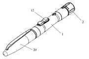
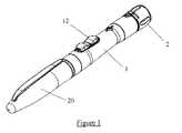
- FIG. 1shows schematically a pen-type injector
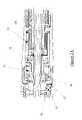
- FIG. 2shows a horizontal cross-section through the injector of FIG. 1 ;
- FIG. 2Ashows an enlarged view of a retaining and trigger portion of the injector taken at A of FIG. 2 ;
- FIG. 3shows a vertical cross-section through the injector of FIG. 1 ;
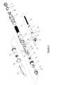
- FIG. 4is a perspective exploded view of the injector of FIG. 1 ;
- FIG. 5shows a dose knob of the injector of FIG. 1 ;
- FIG. 6shows a clutch collet of the injector of FIG. 1 ;
- FIG. 7shows in partial cross-section of an end of the injector of FIG. 1 ;
- FIG. 8illustrates an operating sequence of the injector of FIG. 1 ;
- FIG. 9shows a horizontal side elevation view of a dose knob
- FIG. 10is a perspective view of a locking bush and a leadscrew
- FIG. 11shows a horizontal cross-section through an alternative internal construction of the injector
- FIG. 11Ashows an enlarged view of a retaining and trigger portion of the injector taken at A of FIG. 11 ;
- FIG. 12shows a vertical cross-section through the alternative injector of FIG. 9 ;
- FIG. 13is a perspective exploded view of the injector of FIG. 9 ;
- FIG. 14shows perspective views of an end of a drive shaft of the injector of FIG. 9 .
- FIG. 1a pen-type injector having a user operable dose setting mechanism.
- the injectorcomprises a main body 1 and a cap 20 which snap fit together.
- Identity ring 19is colour coded to indicate the type of medicament to be delivered by the injector.
- a screw threadis provided on an inner surface of the main body 1 at its upper end. This internal screw thread is engaged by an external screw thread 2 a provided on an outer surface of a dose knob 2 .
- the dose knob 2is illustrated in detail in FIG. 5 . Longitudinal movement of the dose knob 2 within the pen body 1 is limited in both directions.
- a cartridge housing 18is secured to a lower end of the main body 1 and is arranged to receive a disposable medication filled cartridge (not shown).
- a disposable medication filled cartridge(not shown).
- Such a cartridgehas a rubber bung sealing one end of the cartridge, with the other end being arranged to receive a disposable needle.
- the cartridgeis typically multi-use, with a user attaching a new needle for each injection.
- a torsion spring 4is located coaxially within the main body 1 and is arranged to provide the drive force for ejecting medication from a loaded cartridge.
- the spring 4is fixed at its upper end to the dose knob 5 .
- the spring 4is fixed to the housing via a retaining ring moulded integrally with the housing 1 .
- a generally cylindrical ratchet drive shaft 3extends through the centre of the spring 4 .
- An enlarged end portion 3 a of the shaft 3has three sprung legs 3 b formed around its periphery, the legs being spaced equiangularly around the shaft.
- a tooth 3 cis provided at the outermost end of each leg.
- the teeth 3 cengage teeth of a rack 11 a (not visible in FIG. 4 ) formed around the inner surface of a generally cylindrical drive gear component 11 which sits within the main body 1 at a fixed axial position.
- the drive gear 11has a second toothed rack 11 b formed around a lower outer surface portion. This rack sits within a correspondingly sized rack 12 a formed on an inner surface of a retaining ring 12 .
- the ring 12is formed integrally with a trigger 12 b , with the component being slidably mounted within a slot formed in the main body 1 , separated from the body by a pair of thrust washers 10 .
- a spring 13urges the trigger 12 b in an upward direction, maintaining the racks 11 b , 12 a in locking engagement in the absence of a user force applied to the trigger.
- the dose knob 2 and the trigger 12 bmay be provided with a soft rubber over-molding. This provides the user with a more comfortable and better grip.
- the clutch colletillustrated in FIG. 6 (viewed from above A and below B) rotates with the drive shaft 3 and is provided with a pair of sprung fingers 5 a .
- the sprung fingersare shaped in cross-section to provide respective teeth for engaging teeth of a rack 2 c formed around an inner surface of the dose knob 2 .
- the fingers 5 aare biased outwardly.
- a rewind button 6is located within the dose knob 2 , projecting therefrom.
- the button 6is coupled to the ratchet drive shaft 3 , rotating with the drive shaft but being able to slide longitudinally within the drive shaft.
- a spring 7is coupled between the button 6 and the drive shaft 3 and biases the button outwardly relative to the main body 1 .
- the lower portion of the button 6is generally cross-shaped, with two opposed arms of the cross opposing the sprung fingers 5 a of the clutch collet 5 . These arms taper inwardly such that they prevent any radially inward flexing of the sprung fingers 5 a when the button is in its outer position, whilst allowing inward flexing when the button is fully depressed against the bias of the button spring 7 .
- FIG. 7illustrates the button 6 in situ whilst FIG. 7B illustrates the end of the injector with a cross-section taken through the button 6 .
- a leadscrew 8has a screw thread formed along the length of its outer surface.
- the leadscrewis located within the ratchet drive shaft 3 , and engages a complimentary screw thread formed on the inner surface of the drive gear 11 .
- the end portion of the leadscrew 8 projecting from the ratchet drive shaft 3has a leadscrew cap secured thereto. Rotational movement of the leadscrew relative to the drive shaft is prevented by the engagement of recesses formed along the length of the leadscrew with complimentary splines provided on an inner surface of a locking bush 14 .
- the locking bushis held within a mid-body compartment 17 which itself is secured to the end of the main body 1 via a pair of complimentary screw threads.
- the cartridge compression cup 16On coupling with a medicament containing cartridge, the cartridge compression cup 16 will compress the spring 15 and transmit the loading onto the locking bush 14 .
- the serrated edge of the locking bushengages with the mating features of the body 1 preventing the locking bush from rotating and ensuring that the leadscrew 8 moves forward when subjected to rotation following release of the drive gear 11 .
- An indexing finger 6 adepends from an inner surface of the button 6 .
- the fingeris provided at its end with a ramp shaped tooth 6 b having a vertical, blocking surface and a sloping drive surface.
- the tooth 6 bengages teeth of an indexing rack 2 b formed around an inner surface of the dose knob 2 , when the button is pressed into the dose knob 2 .
- the dose knob 2has a barrel 2 d formed integrally with the dose knob 2 .
- the barrel 2 dhas a series of numbers printed around its circumference, so that as the dose knob 2 is rotated, the barrel 2 d also rotates.
- a window in the main body 1allows the user to see one of the printed numbers, and the printed number relates to the amount of medicament that will be delivered.
- screw thread 2 densures that the dose knob moves linearly with respect to the longitudinal axis of the main body 1 , and allows the dose knob to be rotated over more than one revolution. This allows both higher loading of the torsion spring, and also allows the barrel 2 d to indicate doses over more than one revolution of the barrel, provided that the printed numbers relating to a medicament dose setting are printed in a helical pattern around the outer surface of the barrel 2 d , as shown in FIG. 13 .
- the leadscrew 8comprises a pair of channels 21 running along its longitudinal axis. At one end of each channel is a ramp 22 .
- the locking bush 14comprises a pair of fingers 23 that engage with a corresponding leadscrew channel 21 . This ensures that when the device is assembled, the leadscrew 8 and the locking bush 14 are located correctly together.
- the fingers 23are flexible such that when the leadscrew is passed through the centre of the locking bush 14 , the fingers ride up the corresponding ramps 22 and flex outwards. Once the fingers 23 have passed over the ramps 22 , they snap into engagement with the channels 21 . During resetting, the fingers 23 abut against the corresponding ramps 22 to ensure that the locking bush 14 does not move out of engagement with the leadscrew 8 .
- a usersets a dose by rotating the dose knob 2 in a clockwise direction.
- the top of the spring 4rotates with it creating torsion of the spring.
- Engagement of the sprung fingers 5 a at the top of the ratchet drive shaft 3 with the rack 2 c formed on the inner surface of the dose knob 2also causes the ratchet drive shaft 3 to rotate.
- the teeth of the sprung legs 5 a“click” around the teeth of the rack 11 a . The engagement of the teeth with the rack 11 a prevents the spring 4 unwinding after each click.
- Each clickcorresponds to a predefined angular rotation of the spring and therefore to a predefined ejection dose. It will be readily appreciated that, during the dose setting action, the drive gear 11 is not rotated so no axial movement of the leadscrew 8 is induced. No medication is therefore ejected from the cartridge during the dose setting operation (or indeed air introduced due to back filling).
- the downward movement of the cross-arms of the button 6results in the sprung fingers 5 a being free to flex inwardly, freeing the dose knob 2 and the spring 4 to rotate under one or both of the force stored in the spring and the force induced by the tooth.
- the dose knob 2is able to rotate until the blocking surface of the tooth engages the next stop surface of the upper rack.
- Neither the ratchet drive shaft 3 nor the drive gear 11rotate during this resetting operation. No axial movement of the leadscrew 8 is therefore induced and no medication ejected from the cartridge.
- the dose resetting mechanismoperates by temporarily decoupling the dose knob and the torsion spring from the ratchet drive shaft allowing the former to rotate relative to the drive shaft.
- the rewind button spring 7Upon removal of the pressure from the button 6 , the rewind button spring 7 returns the button to its outermost position, whereupon the teeth of the sprung fingers 5 a reengage with the teeth of the rack 2 c.
- FIGS. 11 to 14An alternative pen-type injector will now be described with reference to FIGS. 11 to 14 . Externally, this injector has a similar external appearance to the injector illustrated in FIG. 1 .
- the operating principle of the alternative injectoris similar to that of the injector of FIGS. 2 to 10 in terms of both the dose setting and firing functionality. However, the dose resetting mechanism differs.
- the injectorcomprises a dose setting knob 2 ′ which is coupled to the main body 1 ′ via complimentary screw threads.
- the end of the dose knob 2 ′is closed by a dose knob cap 7 ′ which rotates with the dose knob.
- thishas an end collar 3 a ′ having three radial extending slots formed therein ( FIG. 14 , where FIG. 14A shows the knob 2 with a ratchet retainer removed, FIG. 14B shows the knob with the retainer in situ, and FIG. 14C shows the knob with the retainer in place but shown transparent).
- These slotsreceive respective arms (also referred to as a dial key) 5 a ′ of a ratchet plunger component 5 ′ having a cylindrical body.
- Each arm 5 a ′comprises a moulded spring body and an end tooth, the surfaces of the tooth sloping at the same angle.
- a ratchet retainer 6 ′snaps over the end of the collar 3 a ′ to secure the ratchet plungers in place.
- the teeth of the ratchet plungerproject from the ends of their respective slots by approximately 0.5 mm, and can be deflected radially inwards (by approximately 0.25 mm) as a result of the moulded springs.
- the teeth of the ratchet plunger 5 ′engage the rack (also referred to as a dial cam) formed around the inner surface of the drive gear 11 ′.
- the teeth surfaces of the rackare also equiangular, corresponding to the teeth of the ratchet plunger.
- a userdials up a dose by rotating the dose knob 2 ′ in a clockwise direction.
- the user applied forceis sufficient to overcome the resistance between the teeth of the ratchet plunger 11 ′ and those of the rack of the drive gear 11 ′, the drive gear being held in place against rotation by the trigger 12 ′.
- the teeth of the ratchet plungerare pushed inward into the end collar of the ratchet drive shaft to allow them to ride over the teeth of the rack within the drive gear.
- a userwishes to reduce a set dose, he or she rotates the dose knob in an anti-clockwise direction.
- the shape of the ratchet plunger teethpermits this.
Landscapes
- Health & Medical Sciences (AREA)
- Vascular Medicine (AREA)
- Engineering & Computer Science (AREA)
- Anesthesiology (AREA)
- Biomedical Technology (AREA)
- Heart & Thoracic Surgery (AREA)
- Hematology (AREA)
- Life Sciences & Earth Sciences (AREA)
- Animal Behavior & Ethology (AREA)
- General Health & Medical Sciences (AREA)
- Public Health (AREA)
- Veterinary Medicine (AREA)
- Infusion, Injection, And Reservoir Apparatuses (AREA)
Abstract
Description
- a housing for receiving a medication containing member;
- a drive member mounted within the housing for engaging with the medication containing member and moveable axially within the housing;
- a spring contained within the housing and coupled to the drive member;
- a dose setting knob coupled to said spring, and rotatably coupled to the housing such that rotation of the knob relative to the housing in a first direction results in compression or twisting of the spring;
- a user actuable trigger for releasing the spring to push the drive member through the housing; and
- a user actuable button coupled to said housing for axial motion relative thereto, said button being coupled to said spring to cause the spring to unwind or expand without causing any substantial movement of said drive member.
- spring means for storing a force which when released causes ejection of the medication from a received medication containing member;
- a dose knob which when rotated in a first direction moves the spring to a force storing position, the dose setting knob providing a plurality of discrete setting positions corresponding to respective doses;
- a user actuable trigger for releasing said stored force to eject medication from said medication containing member; and
- a user actuable button arranged to reduce a stored force in the spring without causing ejection of medication from said medication containing member.
- rotating a dose knob of the apparatus in a first direction to one of a plurality of discrete positions corresponding to respective doses; and
- changing the set dose to a reduced dose by depressing a button one or more times.
- a housing for receiving a medication containing member;
- a drive member mounted within the housing for engaging with the medication containing member and moveable axially within the housing;
- a spring contained within the housing and coupled to the drive member;
- a dose setting knob coupled to said spring, and rotatably coupled to the housing such that rotation of the knob relative to the housing in a first direction results in compression or twisting of the spring;
- spring retaining means comprising a toothed rack coupled to one of the housing and the dose knob and at least one spring mounted tooth coupled to the other of the housing and the dose knob, the or each tooth engaging the toothed rack to prevent a force stored on the spring from moving the spring to release the force, whilst allowing a user to rotate the dose knob in a second, reverse direction, to reduce a set dose; and
- a user actuable trigger for releasing the spring to push the drive member through the housing.
- a housing for receiving a medication containing member;
- a drive member mounted within the housing for engaging with the medication containing member and moveable axially within the housing;
- a torsion spring contained within the housing and coupled to the drive member;
- a dose setting knob coupled to said spring, and rotatably coupled to the housing such that rotation of the knob relative to the housing in a first direction results in loading of the spring;
- a user actuable trigger for releasing the spring to push the drive member through the housing; and
- a rotatably mounted visual indicator for indicating the dose to be delivered, the rotatably mounted visual indicator being rotatable over at least one complete revolution.
- a housing for receiving a medication containing member;
- a drive member mounted within the housing for engaging with the medication containing member and moveable axially within the housing;
- a torsion spring contained within the housing and coupled to the drive member;
- a dose setting knob coupled to said spring, and rotatably coupled to the housing such that rotation of the knob relative to the housing in a first direction results in loading of the spring;
- a dial cam configured to co-operate with a dial key, such that upon rotation of the dose setting knob, the dial cam and the dial key co-operate to strain or release the torsion spring, depending upon the direction of rotation of the dose setting knob.
| TABLE 1 | |
| numeral | Description |
| 1 | |
| 2 | Dose Knob - |
| 3 | Ratchet Drive Shaft - No |
| 4 | Torsion Spring - |
| 5 | |
| 6 | |
| 7 | |
| 8 | |
| 9 | |
| 10 | |
| 11 | Drive Gear - No Rewind (1 Unit) |
| 12 | |
| 13 | |
| 14 | |
| 15 | |
| 16 | |
| 17 | Mid-Body |
| 18 | |
| 19 | |
| 20 | |
| 21 | |
| 22 | |
| 23 | Locking bush finger |
| TABLE 2 | |
| numeral | Description |
| 1 | |
| 2 | |
| 3 | |
| 4 | |
| 5 | |
| 6 | |
| 7 | |
| 8 | |
| 9 | |
| 10 | |
| 11 | |
| 12 | |
| 13 | |
| 14 | |
| 15 | |
| 16 | |
| 17 | Mid-Body |
| 18 | |
| 19 | |
| 20 | Cap |
Claims (16)
Priority Applications (1)
| Application Number | Priority Date | Filing Date | Title |
|---|---|---|---|
| US12/561,320US8905971B2 (en) | 2005-12-02 | 2009-09-17 | Injection method and apparatus |
Applications Claiming Priority (4)
| Application Number | Priority Date | Filing Date | Title |
|---|---|---|---|
| GB0524604.6 | 2005-12-02 | ||
| GBGB0524604.6AGB0524604D0 (en) | 2005-12-02 | 2005-12-02 | Injection method and apparatus |
| US11/598,969US20070129687A1 (en) | 2005-12-02 | 2006-11-14 | Injection method and apparatus |
| US12/561,320US8905971B2 (en) | 2005-12-02 | 2009-09-17 | Injection method and apparatus |
Related Parent Applications (1)
| Application Number | Title | Priority Date | Filing Date |
|---|---|---|---|
| US11/598,969ContinuationUS20070129687A1 (en) | 2005-12-02 | 2006-11-14 | Injection method and apparatus |
Publications (2)
| Publication Number | Publication Date |
|---|---|
| US20100069845A1 US20100069845A1 (en) | 2010-03-18 |
| US8905971B2true US8905971B2 (en) | 2014-12-09 |
Family
ID=35685947
Family Applications (2)
| Application Number | Title | Priority Date | Filing Date |
|---|---|---|---|
| US11/598,969AbandonedUS20070129687A1 (en) | 2005-12-02 | 2006-11-14 | Injection method and apparatus |
| US12/561,320Expired - Fee RelatedUS8905971B2 (en) | 2005-12-02 | 2009-09-17 | Injection method and apparatus |
Family Applications Before (1)
| Application Number | Title | Priority Date | Filing Date |
|---|---|---|---|
| US11/598,969AbandonedUS20070129687A1 (en) | 2005-12-02 | 2006-11-14 | Injection method and apparatus |
Country Status (10)
| Country | Link |
|---|---|
| US (2) | US20070129687A1 (en) |
| EP (3) | EP2198906B1 (en) |
| JP (2) | JP5119164B2 (en) |
| CN (1) | CN101321550B (en) |
| DE (1) | DE602006019900D1 (en) |
| DK (1) | DK1954337T3 (en) |
| GB (1) | GB0524604D0 (en) |
| PL (1) | PL1954337T4 (en) |
| RU (1) | RU2395306C2 (en) |
| WO (1) | WO2007063342A1 (en) |
Cited By (4)
| Publication number | Priority date | Publication date | Assignee | Title |
|---|---|---|---|---|
| US10758899B2 (en)* | 2017-05-05 | 2020-09-01 | Eppendorf Ag | Electronic dosing drive |
| US11280389B2 (en)* | 2017-05-05 | 2022-03-22 | Eppendorf Ag | Spindle drive |
| USD996605S1 (en) | 2021-03-29 | 2023-08-22 | Owen Mumford Limited | Injector |
| US11904143B2 (en) | 2017-06-08 | 2024-02-20 | Amgen Inc. | Torque driven drug delivery device |
Families Citing this family (118)
| Publication number | Priority date | Publication date | Assignee | Title |
|---|---|---|---|---|
| US6663602B2 (en) | 2000-06-16 | 2003-12-16 | Novo Nordisk A/S | Injection device |
| US20040098010A1 (en)* | 2001-10-22 | 2004-05-20 | Glenn Davison | Confuser crown skin pricker |
| WO2003068290A2 (en) | 2002-02-11 | 2003-08-21 | Antares Pharma, Inc. | Intradermal injector |
| US9486581B2 (en)* | 2002-09-11 | 2016-11-08 | Becton, Dickinson And Company | Injector device with force lock-out and injection rate limiting mechanisms |
| GB0409354D0 (en)* | 2004-04-27 | 2004-06-02 | Owen Mumford Ltd | Removal of needles |
| MX2007003682A (en) | 2004-10-04 | 2007-08-07 | Sanofi Aventis Deutschland | Drive mechanism for a drug delivery device. |
| ATE444090T1 (en) | 2004-10-21 | 2009-10-15 | Novo Nordisk As | SELECTION MECHANISM FOR A ROTARY PIN |
| HUE042286T2 (en) | 2005-01-24 | 2019-06-28 | Antares Pharma Inc | Needle-filled pre-filled syringe |
| GB0524604D0 (en)* | 2005-12-02 | 2006-01-11 | Owen Mumford Ltd | Injection method and apparatus |
| GB2434103B (en)* | 2006-01-12 | 2009-11-25 | Owen Mumford Ltd | Lancet firing device |
| WO2007131013A1 (en) | 2006-05-03 | 2007-11-15 | Antares Pharma, Inc. | Two-stage reconstituting injector |
| WO2007131025A1 (en) | 2006-05-03 | 2007-11-15 | Antares Pharma, Inc. | Injector with adjustable dosing |
| JP5253387B2 (en) | 2006-05-18 | 2013-07-31 | ノボ・ノルデイスク・エー/エス | Injection device with mode locking means |
| USD600795S1 (en)* | 2006-10-30 | 2009-09-22 | Sanofi-Aventis Deutschland Gmbh | Medical injector |
| CA121972S (en)* | 2007-02-23 | 2008-11-25 | Sanofi Aventis Deutschland | Medical injector |
| USD619702S1 (en)* | 2007-11-15 | 2010-07-13 | Tecpharma Licensing Ag | Medicine injector |
| US8992484B2 (en)* | 2008-01-23 | 2015-03-31 | Novo Nordisk A/S | Device for injecting apportioned doses of liquid drug |
| CA2711653C (en)* | 2008-01-23 | 2016-07-05 | Novo Nordisk A/S | Device for injecting apportioned doses of liquid drug |
| JP5451641B2 (en)* | 2008-02-07 | 2014-03-26 | ノボ・ノルデイスク・エー/エス | Injection device with mode defining element |
| EP3636301A1 (en) | 2008-03-10 | 2020-04-15 | Antares Pharma, Inc. | Injector safety device |
| US8376993B2 (en) | 2008-08-05 | 2013-02-19 | Antares Pharma, Inc. | Multiple dosage injector |
| GB2463034B (en)* | 2008-08-28 | 2012-11-07 | Owen Mumford Ltd | Autoinjection devices |
| CN102202712B (en)* | 2008-09-09 | 2013-07-31 | Shl集团有限责任公司 | Medicament delivery device |
| USD641077S1 (en) | 2008-09-15 | 2011-07-05 | Sanofi-Aventis Deutschland Gmbh | Medical injector |
| USD651305S1 (en) | 2008-10-11 | 2011-12-27 | Sanofi-Aventis Deutschland Gmbh | Medical injector |
| CA130178S (en) | 2008-10-11 | 2010-08-25 | Sanofi Aventis Deutschland | Medical injector |
| EP2373361B1 (en) | 2008-10-24 | 2012-09-12 | Novo Nordisk A/S | Dial-down mechanism for wind-up pen |
| GB2465390A (en) | 2008-11-17 | 2010-05-19 | Owen Mumford Ltd | Syringe needle cover remover |
| EP2198903A1 (en) | 2008-12-19 | 2010-06-23 | Sanofi-Aventis Deutschland GmbH | Motor mechanism for a drug delivery device and drug delivery device |
| EP2198904A1 (en) | 2008-12-19 | 2010-06-23 | Sanofi-Aventis Deutschland GmbH | Interlock mechanism for a drug delivery device and drug delivery device |
| BRPI1006948A2 (en)* | 2009-01-23 | 2016-04-12 | Sanofi Aventis Deutschland | drug identification system for multiple dose injection devices |
| US8529520B2 (en) | 2009-02-06 | 2013-09-10 | Shl Group Ab | Medicament delivery device with electronic dose sensor |
| JP5732039B2 (en) | 2009-03-20 | 2015-06-10 | アンタレス・ファーマ・インコーポレーテッド | Hazardous drug injection system |
| WO2010112565A1 (en) | 2009-03-31 | 2010-10-07 | Sanofi-Aventis Deutschland Gmbh | Dose button for a drug delivery device and method for manufacturing a dose button |
| US9457148B2 (en) | 2009-04-01 | 2016-10-04 | Shl Group Ab | Medicament delivery device |
| US8257319B2 (en)* | 2009-06-01 | 2012-09-04 | Sanofi-Aventis Deutschland Gmbh | Drug delivery device inner housing having helical spline |
| US8870831B2 (en) | 2009-08-24 | 2014-10-28 | Shl Group Ab | Dose reset mechanism |
| GB0918145D0 (en)* | 2009-10-16 | 2009-12-02 | Owen Mumford Ltd | Injector apparatus |
| PL215310B1 (en)* | 2009-10-30 | 2013-11-29 | Kappa Medilab Spolka Z Ograniczona Odpowiedzialnoscia | Automatic applicator, especially for insulin |
| USD685464S1 (en) | 2010-01-11 | 2013-07-02 | Sanofi-Aventis Deutschland Gmbh | Medical injector |
| WO2011101349A1 (en) | 2010-02-17 | 2011-08-25 | Sanofi-Aventis Deutschland Gmbh | Automatic injection device with torsional spring |
| JP5950828B2 (en)* | 2010-02-17 | 2016-07-13 | サノフィ−アベンティス・ドイチュラント・ゲゼルシャフト・ミット・ベシュレンクテル・ハフツング | Injection device |
| ES2484266T3 (en) | 2010-03-01 | 2014-08-11 | Eli Lilly And Company | Automatic injection device with delay mechanism including a double function thrust element |
| WO2011114343A1 (en)* | 2010-03-19 | 2011-09-22 | Pawan Trilokchand Agrawal | Multi dose parental drug delivery system with exchangeable glass cartridge |
| GB201004626D0 (en) | 2010-03-19 | 2010-05-05 | Owen Mumford Ltd | Improved injection device |
| CA2801147C (en)* | 2010-06-03 | 2015-02-24 | Shl Group Ab | Medicament delivery device |
| JP2013533078A (en)* | 2010-08-13 | 2013-08-22 | サノフィ−アベンティス・ドイチュラント・ゲゼルシャフト・ミット・ベシュレンクテル・ハフツング | Identification for drug delivery devices |
| GB201018827D0 (en) | 2010-11-08 | 2010-12-22 | Owen Mumford Ltd | Injection device |
| TWI464003B (en)* | 2010-11-18 | 2014-12-11 | Shl Group Ab | Medicament delivery device |
| USD717428S1 (en) | 2010-11-19 | 2014-11-11 | Sanofi-Aventis Deutschland Gmbh | Medical injector |
| USD725771S1 (en) | 2010-11-19 | 2015-03-31 | Sanofi-Aventis Deutschland Gmbh | Medical injector |
| USD717940S1 (en) | 2010-11-19 | 2014-11-18 | Sanofi-Aventis Deutschland Gmbh | Medical injector |
| USD722158S1 (en) | 2010-11-19 | 2015-02-03 | Sanofi-Aventis Deutschland Gmbh | Medical injector |
| EP2646078A1 (en)* | 2010-11-29 | 2013-10-09 | Sanofi-Aventis Deutschland GmbH | Drug delivery device |
| USD716442S1 (en) | 2010-12-06 | 2014-10-28 | Sanofi-Aventis Deutschland Gmbh | Medical injector |
| USD719257S1 (en) | 2010-12-06 | 2014-12-09 | Sanofi-Aventis Deutschland Gmbh | Medical injector |
| BR112013018905B1 (en) | 2011-01-24 | 2021-07-13 | Abbvie Biotechnology Ltd | AUTOMATIC INJECTION DEVICES THAT HAVE OVERMOLDED HANDLE SURFACES. |
| US9452265B2 (en) | 2011-03-18 | 2016-09-27 | Becton, Dickinson And Company | End of injection indicator for injection pen |
| WO2012154110A1 (en)* | 2011-05-12 | 2012-11-15 | Shl Group Ab | Medical delivery device with dose re-setting |
| USRE50423E1 (en)* | 2011-06-17 | 2025-05-13 | Shl Medical Ag | Injection device |
| US8496619B2 (en)* | 2011-07-15 | 2013-07-30 | Antares Pharma, Inc. | Injection device with cammed ram assembly |
| US9220660B2 (en) | 2011-07-15 | 2015-12-29 | Antares Pharma, Inc. | Liquid-transfer adapter beveled spike |
| USD734450S1 (en)* | 2011-11-01 | 2015-07-14 | Novo Nordisk A/S | Injection device |
| US9468722B2 (en)* | 2011-11-25 | 2016-10-18 | Shl Group Ab | Medicament delivery device |
| JP2015505253A (en)* | 2011-12-06 | 2015-02-19 | ノボ・ノルデイスク・エー/エス | Drive mechanism for an injection device and method of assembling an injection device comprising such a drive mechanism |
| JP6069351B2 (en) | 2011-12-29 | 2017-02-01 | ノボ・ノルデイスク・エー/エス | Torsion spring type automatic syringe with dial-up / dial-down administration mechanism |
| US8834449B2 (en) | 2012-01-23 | 2014-09-16 | Ikomed Technologies, Inc. | Mixing syringe |
| US9751056B2 (en) | 2012-01-23 | 2017-09-05 | Merit Medical Systems, Inc. | Mixing syringe |
| WO2013110538A1 (en) | 2012-01-27 | 2013-08-01 | Novo Nordisk A/S | Injection device with a sliding scale |
| PL220720B1 (en) | 2012-02-08 | 2015-12-31 | Copernicus Spółka Z Ograniczoną Odpowiedzialnością | Injection device with a reset mechanism of the dose |
| US9486583B2 (en) | 2012-03-06 | 2016-11-08 | Antares Pharma, Inc. | Prefilled syringe with breakaway force feature |
| IN2014DN07773A (en)* | 2012-03-15 | 2015-05-15 | Becton Dickinson Co | |
| EP2644218B2 (en)* | 2012-03-30 | 2022-11-02 | Tecpharma Licensing AG | Injection device with dose display and clockwork drive |
| EP4186545A1 (en) | 2012-04-06 | 2023-05-31 | Antares Pharma, Inc. | Needle assisted jet injection administration of testosterone compositions |
| US9364610B2 (en) | 2012-05-07 | 2016-06-14 | Antares Pharma, Inc. | Injection device with cammed ram assembly |
| US10195359B2 (en) | 2012-05-31 | 2019-02-05 | Novo Nordisk A/S | Dial-down mechanism for wind-up pen |
| CN202699777U (en)* | 2012-06-14 | 2013-01-30 | 甘肃成纪生物药业有限公司 | Adjustable injection pen |
| FI3659647T3 (en) | 2013-02-11 | 2024-03-28 | Antares Pharma Inc | NEEDLE-ASSISTED SPRAY INJECTOR WITH REDUCED TRIGGER FORCE |
| CA2905031C (en) | 2013-03-11 | 2018-01-23 | Hans PFLAUMER | Dosage injector with pinion system |
| WO2014165136A1 (en) | 2013-03-12 | 2014-10-09 | Antares Pharma, Inc. | Constant volume prefilled syringes and kits thereof |
| MX2015013058A (en) | 2013-03-14 | 2016-05-31 | Lilly Co Eli | Trigger assembly for an automatic injection device. |
| KR20150119092A (en) | 2013-03-14 | 2015-10-23 | 일라이 릴리 앤드 캄파니 | Delay mechanism suitable for compact automatic injection device |
| US10232118B2 (en)* | 2013-04-10 | 2019-03-19 | Sanofi | Drive assembly for a drug delivery device |
| WO2014166909A1 (en)* | 2013-04-10 | 2014-10-16 | Sanofi | Injection device |
| US10688248B2 (en)* | 2013-04-10 | 2020-06-23 | Sanofi | Injection device |
| EP2983768A1 (en)* | 2013-04-10 | 2016-02-17 | Sanofi | Drive mechanism of a drug delivery device |
| MX2015014293A (en) | 2013-04-10 | 2015-12-08 | Sanofi Sa | Injection device. |
| JP6419159B2 (en)* | 2013-04-10 | 2018-11-07 | サノフイSanofi | Injection device |
| GB2516071B (en) | 2013-07-10 | 2016-01-06 | Owen Mumford Ltd | Control of plunger position in an injection device |
| CN105682712B (en)* | 2013-09-03 | 2020-06-26 | 赛诺菲 | Mechanism for a drug delivery device and drug delivery device comprising the mechanism |
| TW201521810A (en)* | 2013-09-03 | 2015-06-16 | Sanofi Sa | Drive mechanism |
| DK3043842T3 (en)* | 2013-09-10 | 2019-02-18 | Sanofi Sa | DRIVE MECHANISM FOR A PHARMACEUTICAL ADMINISTRATION DEVICE |
| GB2509348B (en)* | 2013-09-10 | 2016-03-30 | Owen Mumford Ltd | Leak prevention in injection device |
| CN105611959A (en)* | 2013-10-16 | 2016-05-25 | 诺和诺德股份有限公司 | Drug delivery device with improved dose reset mechanism |
| JP6566946B2 (en)* | 2013-11-22 | 2019-08-28 | サノフィ−アベンティス・ドイチュラント・ゲゼルシャフト・ミット・ベシュレンクテル・ハフツング | Drug delivery device having anti-counterfeit function |
| TW201611853A (en) | 2014-07-01 | 2016-04-01 | Sanofi Sa | Injection device |
| WO2016055505A1 (en) | 2014-10-08 | 2016-04-14 | Novo Nordisk A/S | A torsion spring for an injection device and an injection device comprising such torsion spring |
| TW201622762A (en)* | 2014-10-09 | 2016-07-01 | 賽諾菲公司 | Insert and drug delivery device herewith |
| US10576212B2 (en)* | 2014-12-08 | 2020-03-03 | Sanofi | Dose setting mechanism and drug delivery device herewith |
| JP6815650B2 (en)* | 2015-04-16 | 2021-01-20 | 株式会社根本杏林堂 | Chemical injection device, control method of chemical injection device, computer program |
| PL414382A1 (en) | 2015-10-15 | 2017-04-24 | Copernicus Spółka Z Ograniczoną Odpowiedzialnością | Setting mechanism, in particular for dosing |
| PL414383A1 (en) | 2015-10-15 | 2017-04-24 | Copernicus Spółka Z Ograniczoną Odpowiedzialnością | Setting mechanism, in particular for dosing pharmaceuticals |
| WO2017070959A1 (en)* | 2015-10-30 | 2017-05-04 | 项文 | Device for controlling puncture depth and hiding needle and usage method thereof |
| EP3368105B1 (en)* | 2015-10-30 | 2020-07-01 | Novo Nordisk A/S | Method of manufacturing prefilled drug delivery devices |
| PL227678B1 (en) | 2015-12-22 | 2018-01-31 | Copernicus Spolka Z Ograniczona Odpowiedzialnoscia | Control and drive system for the device intended for injection and the device for making injections equipped with such a system |
| PL3108914T3 (en) | 2016-07-07 | 2019-08-30 | Copernicus Sp. Z O.O. | Injection device for delivering a defined number of equal doses of a liquid substance |
| CN106037829B (en)* | 2016-07-15 | 2023-07-28 | 沈阳何氏眼科医院有限公司 | Ocular surface cell sampling system |
| GB201615447D0 (en) | 2016-09-12 | 2016-10-26 | Norton Healthcare Ltd | Dose delivery mechanism |
| GB201615433D0 (en) | 2016-09-12 | 2016-10-26 | Norton Healthcare Ltd | Dose setting and display mechanism |
| RU2653688C1 (en)* | 2017-01-19 | 2018-05-11 | Бектон, Дикинсон Энд Компани | Disposable syringe-pen for several doses |
| CN107050575B (en)* | 2017-04-24 | 2023-02-24 | 无锡市馨亿生物医疗科技有限公司 | Pen type injector capable of being repeatedly used |
| PL232651B1 (en) | 2017-07-18 | 2019-07-31 | Copernicus Spolka Z Ograniczona Odpowiedzialnoscia | Coupling with locking system for the medical injecting device |
| EP3717045A1 (en)* | 2017-11-27 | 2020-10-07 | Sanofi | Ratchet systems for drug delivery devices |
| US11439500B2 (en)* | 2018-12-20 | 2022-09-13 | Alcon Inc. | IOL injector with automatic driver or assisted manual drive force |
| US11235107B2 (en)* | 2019-07-23 | 2022-02-01 | Solteam Incorporation | Medical injection system |
| USD926973S1 (en) | 2019-09-05 | 2021-08-03 | Novo Nordisk A/S | Injection device |
| CN114470442A (en)* | 2022-03-02 | 2022-05-13 | 康希诺生物股份公司 | Pen-shaped drug delivery device for aerosol inhalation |
| US20230398306A1 (en)* | 2022-06-10 | 2023-12-14 | Medmix Switzerland Ag | Set of a medicament delivery device and a cover |
Citations (174)
| Publication number | Priority date | Publication date | Assignee | Title |
|---|---|---|---|---|
| US930477A (en) | 1908-08-08 | 1909-08-10 | William Henry Hudson | Trephine. |
| DE1049188B (en) | 1954-06-19 | 1959-01-22 | Hell Rudolf Dr Ing Fa | Gear for converting a reciprocating movement into a periodically advancing movement |
| US3620209A (en) | 1970-05-08 | 1971-11-16 | Harvey Kravitz | Device for reducing the pain of injections of medicines and other biologicals |
| US3659608A (en) | 1969-12-15 | 1972-05-02 | Damon Corp | Snap-acting surgical lancet |
| US3698395A (en) | 1971-03-12 | 1972-10-17 | Harrith M Hasson | Surgical closure |
| US3760809A (en) | 1971-10-22 | 1973-09-25 | Damon Corp | Surgical lancet having casing |
| EP0097748A1 (en) | 1982-06-28 | 1984-01-11 | Gérard Joseph Slama | Pricking device for collecting a droplet of blood |
| US4442836A (en) | 1980-03-22 | 1984-04-17 | Clinicon Mannheim Gmbh | Blood lancet device |
| US4449529A (en) | 1981-11-18 | 1984-05-22 | Becton Dickinson And Company | Automatic retractable lancet assembly |
| US4462405A (en) | 1982-09-27 | 1984-07-31 | Ehrlich Joseph C | Blood letting apparatus |
| US4517978A (en) | 1983-01-13 | 1985-05-21 | Levin Paul D | Blood sampling instrument |
| WO1985004089A1 (en) | 1984-03-09 | 1985-09-26 | Geoffrey Charles Palmer | Apparatus for sampling a fluid |
| USD281383S (en) | 1983-05-25 | 1985-11-19 | Daniel E. Gelles Associates, Inc. | Article display bracket |
| US4553541A (en) | 1981-03-23 | 1985-11-19 | Becton, Dickinson And Co. | Automatic retractable lancet assembly |
| US4565545A (en) | 1982-06-04 | 1986-01-21 | Terumo Kabushiki Kaisha | Catheter insertion device |
| US4646753A (en) | 1985-06-11 | 1987-03-03 | Becton, Dickinson And Company | Blood collector for microcollection container |
| US4653513A (en) | 1985-08-09 | 1987-03-31 | Dombrowski Mitchell P | Blood sampler |
| DE3730469A1 (en) | 1986-09-08 | 1988-06-16 | Wolfgang Dr Med Wagner | Device for suction diagnosis or suction injection |
| WO1988008724A1 (en) | 1987-05-08 | 1988-11-17 | Wilhelm Haselmeier Gmbh + Co. | Injection device with system for controlling its release in the rest position |
| US4820287A (en) | 1986-03-27 | 1989-04-11 | Micro-Mega | Syringe for high pressure injection of fluid or paste products |
| USRE32922E (en) | 1983-01-13 | 1989-05-16 | Paul D. Levin | Blood sampling instrument |
| US4858607A (en) | 1987-10-16 | 1989-08-22 | Pavel Jordan & Associates | Plastic device for injection and obtaining blood samples |
| US4902279A (en) | 1988-10-05 | 1990-02-20 | Autoject Systems Inc. | Liquid medicament safety injector |
| US4917243A (en) | 1988-08-16 | 1990-04-17 | The Board Of Regents, University Of Texas System | Needle disposal device |
| EP0137975B1 (en) | 1983-09-15 | 1990-10-24 | Becton Dickinson and Company | Blood lancet assembly |
| US4967763A (en) | 1989-03-13 | 1990-11-06 | Becton, Dickinson And Company | Platelet stable blood collection assembly |
| US5026388A (en) | 1989-09-26 | 1991-06-25 | Ingalz Thomas J | Single-use skin puncture device |
| WO1991008786A1 (en) | 1989-12-18 | 1991-06-27 | Wayne Crawford | Hypodermic needle sheath |
| US5046612A (en) | 1989-06-01 | 1991-09-10 | Mostarda Jorge F | Safety apparatus for extracting hypodermic needles from the respective syringe |
| USD322211S (en) | 1989-06-09 | 1991-12-10 | Gary Products Group, Inc. | Bracket for decorative lighting |
| EP0295075B1 (en) | 1987-06-12 | 1991-12-11 | Hypoguard (Uk) Limited | Measured dose syringe |
| US5104388A (en) | 1990-05-08 | 1992-04-14 | Fbk International Corporation | Membrane splittable tubing |
| US5104380A (en) | 1988-04-18 | 1992-04-14 | Robert Charles Turner | Syringe with dose metering device |
| EP0327910B1 (en) | 1988-02-10 | 1992-04-15 | D.C.P. Af 1988 A/S | A dosage unit for dosing a number of measured quantities of a liquid, such as an insulin preparation, from a cartridge |
| US5116353A (en) | 1990-10-05 | 1992-05-26 | United States Surgical Corporation | Safety trocar |
| USD327321S (en) | 1990-03-19 | 1992-06-23 | Infection Control Products, Inc. | Cannula protecting shield |
| USD327214S (en) | 1988-08-30 | 1992-06-23 | El Barador Holding Pty. Ltd. | Bracket for anchoring posts, wall panels or the like |
| US5147306A (en) | 1991-07-01 | 1992-09-15 | Gubich Stephen J | Device for puckering the flesh to facilitate injections |
| US5201324A (en) | 1989-03-27 | 1993-04-13 | Remi Swierczek | Disposable skin perforator and blood testing device |
| US5226895A (en) | 1989-06-05 | 1993-07-13 | Eli Lilly And Company | Multiple dose injection pen |
| US5226896A (en) | 1990-04-04 | 1993-07-13 | Eli Lilly And Company | Dose indicating injection pen |
| US5242421A (en) | 1991-08-06 | 1993-09-07 | Chan Mark S H | Needle cap |
| US5279585A (en)* | 1992-02-04 | 1994-01-18 | Becton, Dickinson And Company | Medication delivery pen having improved dose delivery features |
| US5320609A (en)* | 1992-12-07 | 1994-06-14 | Habley Medical Technology Corporation | Automatic pharmaceutical dispensing syringe |
| US5324303A (en) | 1992-09-25 | 1994-06-28 | Amg Medical, Inc. | Combined lancet and multi-function cap and lancet injector for use therewith |
| US5353806A (en) | 1993-03-04 | 1994-10-11 | The Venture Fund Of Washington | Liquid collection device |
| US5364362A (en) | 1992-02-19 | 1994-11-15 | Henke-Sass, Wolf Gmbh | Front syringe attachment for hypodermic syringes for subcutaneous injection in veterinary medicine |
| US5368047A (en) | 1993-04-28 | 1994-11-29 | Nissho Corporation | Suction-type blood sampler |
| US5383865A (en) | 1993-03-15 | 1995-01-24 | Eli Lilly And Company | Medication dispensing device |
| US5402798A (en) | 1991-07-18 | 1995-04-04 | Swierczek; Remi | Disposable skin perforator and blood testing device |
| US5439453A (en) | 1994-03-25 | 1995-08-08 | Kashanchi; Behnam | Hypodermic needle storage apparatus |
| US5439473A (en) | 1993-12-13 | 1995-08-08 | Modulohm A/S | Safety lancet |
| USD362064S (en) | 1994-06-02 | 1995-09-05 | Smick Ronald H | I.V. needle insertion guide |
| US5454828A (en) | 1994-03-16 | 1995-10-03 | Schraga; Steven | Lancet unit with safety sleeve |
| US5472433A (en) | 1992-12-22 | 1995-12-05 | Suzuki; George R. | Disposable safety guard for syringe needles and the like |
| US5487748A (en) | 1992-04-01 | 1996-01-30 | Owen Mumford Limited | Blood sampling device |
| WO1996007443A1 (en) | 1994-09-08 | 1996-03-14 | Owen Mumford Limited | Improvements relating to injection devices |
| US5514097A (en) | 1994-02-14 | 1996-05-07 | Genentech, Inc. | Self administered injection pen apparatus and method |
| US5527296A (en) | 1994-03-25 | 1996-06-18 | Kashanchi; Behnam | Hypodermic needle storage apparatus |
| US5529581A (en) | 1994-05-17 | 1996-06-25 | International Technidyne Corporation | Lancet device for creating a skin incision |
| US5547702A (en) | 1994-07-08 | 1996-08-20 | Polymer Technology International Corporation | Method for continuous manufacture of diagnostic test strips |
| US5552117A (en) | 1994-04-08 | 1996-09-03 | Becton Dickinson And Company | Collection assembly having a cap lifting mechanism |
| US5554166A (en) | 1993-06-21 | 1996-09-10 | Boehringer Mannheim Gmbh | Blood lancet device for withdrawing blood for diagnostic purposes |
| US5569286A (en) | 1995-03-29 | 1996-10-29 | Becton Dickinson And Company | Lancet assembly |
| US5580794A (en) | 1993-08-24 | 1996-12-03 | Metrika Laboratories, Inc. | Disposable electronic assay device |
| US5591136A (en) | 1991-04-15 | 1997-01-07 | Medico Development Investment Company | Injection device |
| US5601588A (en) | 1994-09-29 | 1997-02-11 | Olympus Optical Co., Ltd. | Endoscopic puncture needle |
| WO1997004707A1 (en) | 1995-07-28 | 1997-02-13 | Apls Co., Ltd. | Assembly for adjusting piercing depth of lancet |
| US5609577A (en) | 1996-01-29 | 1997-03-11 | Haber; Terry M. | Automatically locking hypodermic needle hiding shield for a dose metering syringe |
| WO1997008986A1 (en) | 1995-09-01 | 1997-03-13 | Biosafe Diagnostics Corporation | Blood collection and testing device |
| US5611809A (en) | 1994-11-04 | 1997-03-18 | Owen Mumford Limited | Needle devices for medical use |
| US5613978A (en) | 1996-06-04 | 1997-03-25 | Palco Laboratories | Adjustable tip for lancet device |
| US5626566A (en) | 1991-10-18 | 1997-05-06 | Novo Nordisk A/S | Large dose pen |
| US5628764A (en) | 1995-03-21 | 1997-05-13 | Schraga; Steven | Collar lancet device |
| EP0555554B1 (en) | 1992-02-13 | 1997-11-26 | Kabushiki Kaisya Advance | Simple blood sampling device |
| US5707384A (en) | 1995-06-26 | 1998-01-13 | Teramecs Co., Ltd. | Lancet device for obtaining blood samples |
| US5725508A (en) | 1994-06-22 | 1998-03-10 | Becton Dickinson And Company | Quick connect medication delivery pen |
| WO1998006331A3 (en) | 1996-08-13 | 1998-04-16 | Owen Mumford Ltd | Improvements relating to skin prickers |
| US5743889A (en) | 1992-12-18 | 1998-04-28 | Sams; Bernard | Incrementing dosage mechanism for syringe |
| US5749886A (en) | 1993-06-18 | 1998-05-12 | Leonard Bloom | Disposable guarded finger scalpel for inserting a line in a patient and blade therefor |
| US5797942A (en) | 1996-09-23 | 1998-08-25 | Schraga; Steven | Re-usable end cap for re-usable lancet devices for removing and disposing of a contaminated lancet |
| US5827232A (en) | 1994-06-22 | 1998-10-27 | Becton Dickinson And Company | Quick connect medication delivery pen |
| US5837546A (en) | 1993-08-24 | 1998-11-17 | Metrika, Inc. | Electronic assay device and method |
| US5871494A (en) | 1997-12-04 | 1999-02-16 | Hewlett-Packard Company | Reproducible lancing for sampling blood |
| US5872713A (en) | 1996-10-30 | 1999-02-16 | Mercury Diagnostics, Inc. | Synchronized analyte testing system |
| US5879367A (en) | 1995-09-08 | 1999-03-09 | Integ, Inc. | Enhanced interstitial fluid collection |
| US5879311A (en) | 1996-05-17 | 1999-03-09 | Mercury Diagnostics, Inc. | Body fluid sampling device and methods of use |
| WO1999006100A3 (en) | 1997-07-31 | 1999-04-08 | Owen Mumford Ltd | Improvements relating to injection devices |
| US5910147A (en) | 1996-12-31 | 1999-06-08 | Donald J. Ersler | Angled replaceable comedone extractor |
| WO1998011821A8 (en) | 1996-09-18 | 1999-06-17 | Owen Mumford Ltd | Lancet device |
| US5916230A (en) | 1997-06-16 | 1999-06-29 | Bayer Corporation | Blood sampling device with adjustable end cap |
| WO1999038554A1 (en) | 1998-01-30 | 1999-08-05 | Novo Nordisk A/S | An injection syringe |
| US5951493A (en) | 1997-05-16 | 1999-09-14 | Mercury Diagnostics, Inc. | Methods and apparatus for expressing body fluid from an incision |
| USD421214S (en) | 1998-08-25 | 2000-02-29 | Koros Tibor B | Detachable clamp for a rotatable retractor blade |
| US6053930A (en) | 1998-05-11 | 2000-04-25 | Ruppert; Norbert | Single use lancet assembly |
| US6056765A (en) | 1997-06-24 | 2000-05-02 | Bajaj; Ratan | Lancet device |
| US6071249A (en) | 1996-12-06 | 2000-06-06 | Abbott Laboratories | Method and apparatus for obtaining blood for diagnostic tests |
| US6106539A (en) | 1998-04-15 | 2000-08-22 | Neosurg Technologies | Trocar with removable, replaceable tip |
| US6132449A (en) | 1999-03-08 | 2000-10-17 | Agilent Technologies, Inc. | Extraction and transportation of blood for analysis |
| US6152942A (en) | 1999-06-14 | 2000-11-28 | Bayer Corporation | Vacuum assisted lancing device |
| US6159181A (en) | 1998-04-18 | 2000-12-12 | Owen Mumford Limited Of Brook Hill | Injection device |
| WO2001013794A1 (en) | 1999-08-19 | 2001-03-01 | Owen Mumford Limited | Lancet |
| US6197040B1 (en) | 1999-02-23 | 2001-03-06 | Lifescan, Inc. | Lancing device having a releasable connector |
| US6210420B1 (en) | 1999-01-19 | 2001-04-03 | Agilent Technologies, Inc. | Apparatus and method for efficient blood sampling with lancet |
| US6248095B1 (en) | 1998-02-23 | 2001-06-19 | Becton, Dickinson And Company | Low-cost medication delivery pen |
| US6261245B1 (en) | 1998-01-22 | 2001-07-17 | Terumo Kabushiki Kaisha | Body-fluid inspection device |
| USD446107S1 (en) | 1999-09-30 | 2001-08-07 | Douglas M. Carter | Deadbolt security plate |
| US6277097B1 (en) | 1997-03-25 | 2001-08-21 | Novo Nordisk A/S | Injection system |
| WO2001062150A1 (en) | 2000-02-22 | 2001-08-30 | Owen Mumford Limited | Improvements relating to skin prickers |
| US6283982B1 (en) | 1999-10-19 | 2001-09-04 | Facet Technologies, Inc. | Lancing device and method of sample collection |
| WO2001072361A1 (en) | 2000-03-24 | 2001-10-04 | Bernard Sams | One-way clutch mechanisms and injector devices |
| US6306152B1 (en) | 1999-03-08 | 2001-10-23 | Agilent Technologies, Inc. | Lancet device with skin movement control and ballistic preload |
| US6319209B1 (en) | 1999-08-23 | 2001-11-20 | European Institute Of Science | Disposable test vial with sample delivery device for dispensing sample into a reagent |
| US6332871B1 (en) | 1996-05-17 | 2001-12-25 | Amira Medical | Blood and interstitial fluid sampling device |
| US20020004196A1 (en) | 2000-07-10 | 2002-01-10 | Bayer Corporation | Thin lance and test sensor having same |
| US20020013602A1 (en) | 2000-07-31 | 2002-01-31 | Huttner James J. | Method for controlling the pain from injections or minor surgical procedures and apparatus for use therewith |
| US20020016606A1 (en) | 2000-06-09 | 2002-02-07 | Piet Moerman | Cap for a lancing device |
| US20020082521A1 (en) | 2000-12-22 | 2002-06-27 | Ashutosh Sharma | Alternate-site lancer |
| WO2002030495A3 (en) | 2000-10-09 | 2002-07-04 | Lilly Co Eli | Pen device for administration of parathyroid hormone |
| WO2002053214A1 (en) | 2001-01-05 | 2002-07-11 | Novo Nordisk A/S | Automatic injection device with reset feature |
| US6419661B1 (en) | 1999-03-05 | 2002-07-16 | Roche Diagnostics Gmbh | Device for withdrawing blood for diagnostic applications |
| US20020130042A1 (en) | 2000-03-02 | 2002-09-19 | Moerman Piet H.C. | Combined lancet and electrochemical analyte-testing apparatus |
| US6464649B1 (en) | 1997-11-21 | 2002-10-15 | Amira Medical | Body fluid sampling device |
| US20020198444A1 (en) | 1999-12-13 | 2002-12-26 | Takatoshi Uchigaki | Body fluid measuring apparatus with lancet and lancet holder used for the measuring apparatus |
| USD470391S1 (en) | 2001-10-12 | 2003-02-18 | Reese Products, Inc. | Sway control bracket |
| US20030050655A1 (en) | 2001-09-07 | 2003-03-13 | Roe Steven N. | Rotatable penetration depth adjusting arrangement |
| US6540762B1 (en) | 1998-07-09 | 2003-04-01 | November Aktiengesellschaft Gesellschaft Fur Molekulare Medizin | Device for perforating skin |
| US6558402B1 (en) | 1999-08-03 | 2003-05-06 | Becton, Dickinson And Company | Lancer |
| EP0897728B1 (en) | 1997-08-11 | 2003-05-07 | Becton, Dickinson and Company | Medication delivery pen |
| US6589210B1 (en) | 1999-02-17 | 2003-07-08 | Owen Mumford Limited | Injection devices |
| US6607508B2 (en) | 2000-04-27 | 2003-08-19 | Invivotech, Inc. | Vial injector device |
| US6616640B2 (en) | 2002-01-07 | 2003-09-09 | Marina Ling-Ko Chen | Syringe with plunger anti-detachment mechanism |
| WO2003097133A1 (en) | 2002-05-17 | 2003-11-27 | Owen Mumford Limited | Injection device with automatically retractable needle |
| WO2004002556A1 (en) | 2002-06-28 | 2004-01-08 | Tecpharma Licensing Ag | Product distribution device with rapid piston rod resetting |
| US20040098010A1 (en) | 2001-10-22 | 2004-05-20 | Glenn Davison | Confuser crown skin pricker |
| US6755805B1 (en) | 2002-09-13 | 2004-06-29 | Alan Reid | Needle device having enhanced safety |
| US20040158271A1 (en) | 2001-06-11 | 2004-08-12 | Katsumi Hamamoto | Puncturing element integration mounting body, and method of producing the same |
| US20040162573A1 (en) | 2003-02-19 | 2004-08-19 | Kheiri Mohammad A. | Endcap for lancing device and method of use |
| WO2004082748A1 (en) | 2003-03-22 | 2004-09-30 | Dca Design International Ltd. | Dose dial and drive mechanism suitable for use in drug delivery devices |
| EP0956874B1 (en) | 1998-05-15 | 2004-11-03 | Tecpharma Licensing AG | Device for the dosed application of an injectable product |
| US20050038465A1 (en) | 2003-08-15 | 2005-02-17 | Stat Medical Devices, Inc. | Adjustable lancet device and method |
| WO2005013825A1 (en) | 2003-08-06 | 2005-02-17 | Owen Mumford Limited | Improvements relating to blood sampling devices |
| WO2005020816A1 (en) | 2003-08-29 | 2005-03-10 | Owen Mumford Limited | Improvements relating to lancets |
| WO2004093940A3 (en) | 2003-04-03 | 2005-03-24 | Becton Dickinson Co | Medication delivery pen |
| EP1570792A1 (en) | 1999-03-02 | 2005-09-07 | Asahi Polyslider Co., Ltd. | Lancet apparatus for producing a precisely controlled incision |
| US20050197625A1 (en) | 2002-08-30 | 2005-09-08 | Ulrich Haueter | Device for the dosed discharging of a liquid agent and infusion pump |
| US6945961B2 (en) | 2002-07-10 | 2005-09-20 | Novo Nordisk A/S | Injection device |
| WO2006013532A1 (en) | 2004-07-26 | 2006-02-09 | Nova Biomedical Corporation | Lancet, lancet assembly and lancet-sensor combination |
| USD516218S1 (en) | 2004-04-15 | 2006-02-28 | Larocca Robert J | Wrist device |
| WO2006045526A1 (en) | 2004-10-21 | 2006-05-04 | Novo Nordisk A/S | Dial-down mechanism for wind-up pen |
| WO2006045529A1 (en) | 2004-10-21 | 2006-05-04 | Novo Nordisk A/S | Injection device with internal dose indicator |
| WO2006045528A1 (en) | 2004-10-21 | 2006-05-04 | Novo Nordisk A/S | Injection device with torsion spring and rotatable display |
| WO2006058654A3 (en) | 2004-12-02 | 2006-09-21 | Roche Diagnostics Gmbh | Pricking device for taking blood |
| US7112187B2 (en)* | 2002-09-24 | 2006-09-26 | Shl Medical Ab | Injecting device |
| USD529792S1 (en) | 2004-09-03 | 2006-10-10 | Lynk, Inc. | Hanger bracket for hanging shoe racks |
| US20060229652A1 (en) | 2003-07-31 | 2006-10-12 | Matsushita Electric Industrial Co., Ltd | Puncturing instrument, puncturing needle cartridge, puncturing instrument set, and puncturing needle discardment instrument |
| US20060259058A1 (en) | 2005-04-07 | 2006-11-16 | Schiff David R | Push activation lancet device |
| EP1785090A1 (en) | 2005-11-10 | 2007-05-16 | F.Hoffmann-La Roche Ag | Lancet device and system for skin detection |
| US20070129687A1 (en) | 2005-12-02 | 2007-06-07 | Jeremy Marshall | Injection method and apparatus |
| US7241278B2 (en) | 2000-06-16 | 2007-07-10 | Novo Nordisk A/S | Injection device |
| US20070162063A1 (en) | 2006-01-12 | 2007-07-12 | Owen Mumford, Ltd. | Lancet firing device |
| US7244266B2 (en) | 2002-02-15 | 2007-07-17 | Roche Diagnostics Operations, Inc. | System for pain-reduced withdrawal of blood |
| US20070225742A1 (en) | 2004-05-17 | 2007-09-27 | Teruyuki Abe | Lancet Assembly |
| US20070233166A1 (en) | 2004-05-27 | 2007-10-04 | Facet Technologies, Llc | Low-Cost Lancing Device with Cantilevered Leaf Spring for Launch and Return |
| WO1991010460A9 (en) | 1990-01-22 | 2007-10-04 | Novo Nordisk As | A process and apparatus for mixing and injecting a medicine |
| WO2006092309A8 (en) | 2005-03-03 | 2007-11-22 | Roche Diagnostics Gmbh | Piercing system for removing a bodily fluid |
| US20070299394A1 (en) | 2004-04-27 | 2007-12-27 | Rolfe Steven M G | Apparatus for Removing Needle Assembly |
| GB2440119A (en) | 2006-07-18 | 2008-01-23 | Owen Mumford Ltd | Skin Pricking Device |
| WO2008009984A1 (en) | 2006-07-18 | 2008-01-24 | Owen Mumford Limited | Skin pricking device |
| US20080033469A1 (en) | 2006-08-02 | 2008-02-07 | Sven Winheim | Blood withdrawal system |
| US20080306446A1 (en) | 2005-01-21 | 2008-12-11 | Novo Nordisk A/S | Automatic Injection Device with a Top Release Mechanism |
| GB2465391A (en) | 2008-11-17 | 2010-05-19 | Owen Mumford Ltd | Skin pricking device |
| US20100179485A1 (en)* | 2004-12-01 | 2010-07-15 | Novo Nordisk A/S | Injection device |
| DE102004045043B4 (en) | 2004-09-15 | 2013-09-12 | Balda Medical Gmbh & Co. Kg | Treatment device for blood collection |
Family Cites Families (13)
| Publication number | Priority date | Publication date | Assignee | Title |
|---|---|---|---|---|
| JPS58142028A (en)* | 1982-02-13 | 1983-08-23 | Fumiaki Hasegawa | Torque limiter |
| DE3635163A1 (en)* | 1986-10-16 | 1988-05-05 | Walterscheid Gmbh Jean | OVERLOAD CLUTCH FOR SECURING DRIVE GEARS, ESPECIALLY ON AGRICULTURAL MACHINERY |
| IL90545A (en)* | 1989-06-06 | 1994-07-31 | Orbot Systems Ltd | Immobilizing device for printed-circuit boards |
| US5584815A (en)* | 1993-04-02 | 1996-12-17 | Eli Lilly And Company | Multi-cartridge medication injection device |
| ZA941881B (en)* | 1993-04-02 | 1995-09-18 | Lilly Co Eli | Manifold medication injection apparatus and method |
| US5479886A (en)* | 1995-05-12 | 1996-01-02 | Cummins Engine | Engine oil capacitor |
| DE19838760A1 (en)* | 1998-08-26 | 2000-04-20 | Bauer Jlona | Injection unit, especially for injecting medicines such as insulin, consists of a housing with a chamber for holding a needle, a cartridge and a release mechanism. |
| TW453884B (en)* | 1999-09-16 | 2001-09-11 | Novo Nordisk As | Dose setting limiter |
| DE10002748B4 (en)* | 2000-01-22 | 2006-05-18 | Robert Bosch Gmbh | Hand tool with a safety clutch |
| DE10046279A1 (en)* | 2000-09-19 | 2002-04-04 | Disetronic Licensing Ag | Device for the dosed administration of an injectable product |
| GB0304822D0 (en)* | 2003-03-03 | 2003-04-09 | Dca Internat Ltd | Improvements in and relating to a pen-type injector |
| DE20317377U1 (en)* | 2003-11-03 | 2005-03-17 | B D Medico S A R L | injection device |
| US20070156183A1 (en)* | 2006-01-05 | 2007-07-05 | Rhodes Donald A | Treatment of various ailments |
- 2005
- 2005-12-02GBGBGB0524604.6Apatent/GB0524604D0/ennot_activeCeased
- 2006
- 2006-11-14USUS11/598,969patent/US20070129687A1/ennot_activeAbandoned
- 2006-11-28PLPL06808780Tpatent/PL1954337T4/enunknown
- 2006-11-28EPEP09178013.0Apatent/EP2198906B1/ennot_activeNot-in-force
- 2006-11-28RURU2008125049/14Apatent/RU2395306C2/ennot_activeIP Right Cessation
- 2006-11-28CNCN2006800453541Apatent/CN101321550B/ennot_activeExpired - Fee Related
- 2006-11-28JPJP2008542842Apatent/JP5119164B2/ennot_activeExpired - Fee Related
- 2006-11-28EPEP15202981.5Apatent/EP3020433B1/enactiveActive
- 2006-11-28WOPCT/GB2006/050416patent/WO2007063342A1/enactiveApplication Filing
- 2006-11-28DKDK06808780.8Tpatent/DK1954337T3/enactive
- 2006-11-28DEDE602006019900Tpatent/DE602006019900D1/enactiveActive
- 2006-11-28EPEP06808780Apatent/EP1954337B1/ennot_activeNot-in-force
- 2009
- 2009-09-17USUS12/561,320patent/US8905971B2/ennot_activeExpired - Fee Related
- 2012
- 2012-05-18JPJP2012114710Apatent/JP2012148198A/enactivePending
Patent Citations (219)
| Publication number | Priority date | Publication date | Assignee | Title |
|---|---|---|---|---|
| US930477A (en) | 1908-08-08 | 1909-08-10 | William Henry Hudson | Trephine. |
| DE1049188B (en) | 1954-06-19 | 1959-01-22 | Hell Rudolf Dr Ing Fa | Gear for converting a reciprocating movement into a periodically advancing movement |
| US3659608A (en) | 1969-12-15 | 1972-05-02 | Damon Corp | Snap-acting surgical lancet |
| US3620209A (en) | 1970-05-08 | 1971-11-16 | Harvey Kravitz | Device for reducing the pain of injections of medicines and other biologicals |
| US3698395A (en) | 1971-03-12 | 1972-10-17 | Harrith M Hasson | Surgical closure |
| US3760809A (en) | 1971-10-22 | 1973-09-25 | Damon Corp | Surgical lancet having casing |
| US4442836A (en) | 1980-03-22 | 1984-04-17 | Clinicon Mannheim Gmbh | Blood lancet device |
| US4553541A (en) | 1981-03-23 | 1985-11-19 | Becton, Dickinson And Co. | Automatic retractable lancet assembly |
| US4449529A (en) | 1981-11-18 | 1984-05-22 | Becton Dickinson And Company | Automatic retractable lancet assembly |
| US4565545A (en) | 1982-06-04 | 1986-01-21 | Terumo Kabushiki Kaisha | Catheter insertion device |
| EP0097748A1 (en) | 1982-06-28 | 1984-01-11 | Gérard Joseph Slama | Pricking device for collecting a droplet of blood |
| US4462405A (en) | 1982-09-27 | 1984-07-31 | Ehrlich Joseph C | Blood letting apparatus |
| US4517978A (en) | 1983-01-13 | 1985-05-21 | Levin Paul D | Blood sampling instrument |
| USRE32922E (en) | 1983-01-13 | 1989-05-16 | Paul D. Levin | Blood sampling instrument |
| USD281383S (en) | 1983-05-25 | 1985-11-19 | Daniel E. Gelles Associates, Inc. | Article display bracket |
| EP0137975B1 (en) | 1983-09-15 | 1990-10-24 | Becton Dickinson and Company | Blood lancet assembly |
| WO1985004089A1 (en) | 1984-03-09 | 1985-09-26 | Geoffrey Charles Palmer | Apparatus for sampling a fluid |
| US4646753A (en) | 1985-06-11 | 1987-03-03 | Becton, Dickinson And Company | Blood collector for microcollection container |
| US4653513A (en) | 1985-08-09 | 1987-03-31 | Dombrowski Mitchell P | Blood sampler |
| US4820287A (en) | 1986-03-27 | 1989-04-11 | Micro-Mega | Syringe for high pressure injection of fluid or paste products |
| DE3730469A1 (en) | 1986-09-08 | 1988-06-16 | Wolfgang Dr Med Wagner | Device for suction diagnosis or suction injection |
| WO1988008724A1 (en) | 1987-05-08 | 1988-11-17 | Wilhelm Haselmeier Gmbh + Co. | Injection device with system for controlling its release in the rest position |
| EP0295075B1 (en) | 1987-06-12 | 1991-12-11 | Hypoguard (Uk) Limited | Measured dose syringe |
| US4858607A (en) | 1987-10-16 | 1989-08-22 | Pavel Jordan & Associates | Plastic device for injection and obtaining blood samples |
| EP0327910B1 (en) | 1988-02-10 | 1992-04-15 | D.C.P. Af 1988 A/S | A dosage unit for dosing a number of measured quantities of a liquid, such as an insulin preparation, from a cartridge |
| EP0338806B1 (en) | 1988-04-18 | 1994-02-02 | Turner, Robert Charles | Syringes |
| US5104380A (en) | 1988-04-18 | 1992-04-14 | Robert Charles Turner | Syringe with dose metering device |
| US4917243A (en) | 1988-08-16 | 1990-04-17 | The Board Of Regents, University Of Texas System | Needle disposal device |
| USD327214S (en) | 1988-08-30 | 1992-06-23 | El Barador Holding Pty. Ltd. | Bracket for anchoring posts, wall panels or the like |
| US4902279A (en) | 1988-10-05 | 1990-02-20 | Autoject Systems Inc. | Liquid medicament safety injector |
| US4967763A (en) | 1989-03-13 | 1990-11-06 | Becton, Dickinson And Company | Platelet stable blood collection assembly |
| US5201324A (en) | 1989-03-27 | 1993-04-13 | Remi Swierczek | Disposable skin perforator and blood testing device |
| US5046612A (en) | 1989-06-01 | 1991-09-10 | Mostarda Jorge F | Safety apparatus for extracting hypodermic needles from the respective syringe |
| US5226895A (en) | 1989-06-05 | 1993-07-13 | Eli Lilly And Company | Multiple dose injection pen |
| US5308340A (en) | 1989-06-05 | 1994-05-03 | Eli Lilly And Company | Multiple dose injection pen |
| USD322211S (en) | 1989-06-09 | 1991-12-10 | Gary Products Group, Inc. | Bracket for decorative lighting |
| US5026388A (en) | 1989-09-26 | 1991-06-25 | Ingalz Thomas J | Single-use skin puncture device |
| WO1991008786A1 (en) | 1989-12-18 | 1991-06-27 | Wayne Crawford | Hypodermic needle sheath |
| WO1991010460A9 (en) | 1990-01-22 | 2007-10-04 | Novo Nordisk As | A process and apparatus for mixing and injecting a medicine |
| USD327321S (en) | 1990-03-19 | 1992-06-23 | Infection Control Products, Inc. | Cannula protecting shield |
| US5226896A (en) | 1990-04-04 | 1993-07-13 | Eli Lilly And Company | Dose indicating injection pen |
| EP0450905B1 (en) | 1990-04-04 | 1995-10-18 | Eli Lilly And Company | Dose indicating injection pen |
| US5104388A (en) | 1990-05-08 | 1992-04-14 | Fbk International Corporation | Membrane splittable tubing |
| US5116353A (en) | 1990-10-05 | 1992-05-26 | United States Surgical Corporation | Safety trocar |
| US5116353B1 (en) | 1990-10-05 | 1996-09-10 | Digital Voice Systems Inc | Safety trocar |
| US5591136A (en) | 1991-04-15 | 1997-01-07 | Medico Development Investment Company | Injection device |
| US5147306A (en) | 1991-07-01 | 1992-09-15 | Gubich Stephen J | Device for puckering the flesh to facilitate injections |
| US5402798A (en) | 1991-07-18 | 1995-04-04 | Swierczek; Remi | Disposable skin perforator and blood testing device |
| US5242421A (en) | 1991-08-06 | 1993-09-07 | Chan Mark S H | Needle cap |
| US5626566A (en) | 1991-10-18 | 1997-05-06 | Novo Nordisk A/S | Large dose pen |
| US5279585A (en)* | 1992-02-04 | 1994-01-18 | Becton, Dickinson And Company | Medication delivery pen having improved dose delivery features |
| EP0555554B1 (en) | 1992-02-13 | 1997-11-26 | Kabushiki Kaisya Advance | Simple blood sampling device |
| US5364362A (en) | 1992-02-19 | 1994-11-15 | Henke-Sass, Wolf Gmbh | Front syringe attachment for hypodermic syringes for subcutaneous injection in veterinary medicine |
| US5487748A (en) | 1992-04-01 | 1996-01-30 | Owen Mumford Limited | Blood sampling device |
| US5487748B1 (en) | 1992-04-01 | 1998-04-14 | Owen Mumford Ltd | Blood sampling device |
| US5324303A (en) | 1992-09-25 | 1994-06-28 | Amg Medical, Inc. | Combined lancet and multi-function cap and lancet injector for use therewith |
| US5423847A (en) | 1992-09-25 | 1995-06-13 | Amg Medical, Inc. | Safe lancet injector |
| US5320609A (en)* | 1992-12-07 | 1994-06-14 | Habley Medical Technology Corporation | Automatic pharmaceutical dispensing syringe |
| US5743889A (en) | 1992-12-18 | 1998-04-28 | Sams; Bernard | Incrementing dosage mechanism for syringe |
| US5472433A (en) | 1992-12-22 | 1995-12-05 | Suzuki; George R. | Disposable safety guard for syringe needles and the like |
| US5353806A (en) | 1993-03-04 | 1994-10-11 | The Venture Fund Of Washington | Liquid collection device |
| US5383865A (en) | 1993-03-15 | 1995-01-24 | Eli Lilly And Company | Medication dispensing device |
| US5368047A (en) | 1993-04-28 | 1994-11-29 | Nissho Corporation | Suction-type blood sampler |
| US5749886A (en) | 1993-06-18 | 1998-05-12 | Leonard Bloom | Disposable guarded finger scalpel for inserting a line in a patient and blade therefor |
| US5554166A (en) | 1993-06-21 | 1996-09-10 | Boehringer Mannheim Gmbh | Blood lancet device for withdrawing blood for diagnostic purposes |
| US5580794A (en) | 1993-08-24 | 1996-12-03 | Metrika Laboratories, Inc. | Disposable electronic assay device |
| US5837546A (en) | 1993-08-24 | 1998-11-17 | Metrika, Inc. | Electronic assay device and method |
| US5439473A (en) | 1993-12-13 | 1995-08-08 | Modulohm A/S | Safety lancet |
| US5514097A (en) | 1994-02-14 | 1996-05-07 | Genentech, Inc. | Self administered injection pen apparatus and method |
| US5454828A (en) | 1994-03-16 | 1995-10-03 | Schraga; Steven | Lancet unit with safety sleeve |
| US5527296A (en) | 1994-03-25 | 1996-06-18 | Kashanchi; Behnam | Hypodermic needle storage apparatus |
| US5439453A (en) | 1994-03-25 | 1995-08-08 | Kashanchi; Behnam | Hypodermic needle storage apparatus |
| US5552117A (en) | 1994-04-08 | 1996-09-03 | Becton Dickinson And Company | Collection assembly having a cap lifting mechanism |
| US5529581A (en) | 1994-05-17 | 1996-06-25 | International Technidyne Corporation | Lancet device for creating a skin incision |
| USD362064S (en) | 1994-06-02 | 1995-09-05 | Smick Ronald H | I.V. needle insertion guide |
| US5725508A (en) | 1994-06-22 | 1998-03-10 | Becton Dickinson And Company | Quick connect medication delivery pen |
| US5827232A (en) | 1994-06-22 | 1998-10-27 | Becton Dickinson And Company | Quick connect medication delivery pen |
| US5547702A (en) | 1994-07-08 | 1996-08-20 | Polymer Technology International Corporation | Method for continuous manufacture of diagnostic test strips |
| WO1996007443A1 (en) | 1994-09-08 | 1996-03-14 | Owen Mumford Limited | Improvements relating to injection devices |
| US5601588A (en) | 1994-09-29 | 1997-02-11 | Olympus Optical Co., Ltd. | Endoscopic puncture needle |
| US5611809A (en) | 1994-11-04 | 1997-03-18 | Owen Mumford Limited | Needle devices for medical use |
| US5628764A (en) | 1995-03-21 | 1997-05-13 | Schraga; Steven | Collar lancet device |
| US5569286A (en) | 1995-03-29 | 1996-10-29 | Becton Dickinson And Company | Lancet assembly |
| US5707384A (en) | 1995-06-26 | 1998-01-13 | Teramecs Co., Ltd. | Lancet device for obtaining blood samples |
| US5730753A (en) | 1995-07-28 | 1998-03-24 | Apls Co., Ltd. | Assembly for adjusting pricking depth of lancet |
| EP0783868B1 (en) | 1995-07-28 | 2003-04-09 | Apls Co., Ltd. | Assembly for adjusting the piercing depth of a lancet |
| WO1997004707A1 (en) | 1995-07-28 | 1997-02-13 | Apls Co., Ltd. | Assembly for adjusting piercing depth of lancet |
| US5709699A (en) | 1995-09-01 | 1998-01-20 | Biosafe Diagnostics Corporation | Blood collection and testing device |
| WO1997008986A1 (en) | 1995-09-01 | 1997-03-13 | Biosafe Diagnostics Corporation | Blood collection and testing device |
| US5879367A (en) | 1995-09-08 | 1999-03-09 | Integ, Inc. | Enhanced interstitial fluid collection |
| US6203504B1 (en) | 1995-09-08 | 2001-03-20 | Integ, Inc. | Enhanced interstitial fluid collection |
| US5609577A (en) | 1996-01-29 | 1997-03-11 | Haber; Terry M. | Automatically locking hypodermic needle hiding shield for a dose metering syringe |
| US5879311A (en) | 1996-05-17 | 1999-03-09 | Mercury Diagnostics, Inc. | Body fluid sampling device and methods of use |
| US6332871B1 (en) | 1996-05-17 | 2001-12-25 | Amira Medical | Blood and interstitial fluid sampling device |
| US5613978A (en) | 1996-06-04 | 1997-03-25 | Palco Laboratories | Adjustable tip for lancet device |
| WO1998006331A3 (en) | 1996-08-13 | 1998-04-16 | Owen Mumford Ltd | Improvements relating to skin prickers |
| EP0925021B1 (en) | 1996-08-13 | 2003-11-19 | Owen Mumford Limited | Improvements relating to skin prickers |
| JP2001507250A (en) | 1996-09-18 | 2001-06-05 | オーエン マムフォード リミテッド | Lancet device |
| WO1998011821A8 (en) | 1996-09-18 | 1999-06-17 | Owen Mumford Ltd | Lancet device |
| US6136013A (en) | 1996-09-18 | 2000-10-24 | Owen Mumford Limited | Lancet device |
| US5797942A (en) | 1996-09-23 | 1998-08-25 | Schraga; Steven | Re-usable end cap for re-usable lancet devices for removing and disposing of a contaminated lancet |
| US5872713A (en) | 1996-10-30 | 1999-02-16 | Mercury Diagnostics, Inc. | Synchronized analyte testing system |
| US6071249A (en) | 1996-12-06 | 2000-06-06 | Abbott Laboratories | Method and apparatus for obtaining blood for diagnostic tests |
| US6093156A (en) | 1996-12-06 | 2000-07-25 | Abbott Laboratories | Method and apparatus for obtaining blood for diagnostic tests |
| US20020169393A1 (en) | 1996-12-06 | 2002-11-14 | Cunningham David D. | Method and apparatus for obtaining blood for diagnostic tests |
| US5910147A (en) | 1996-12-31 | 1999-06-08 | Donald J. Ersler | Angled replaceable comedone extractor |
| US6277097B1 (en) | 1997-03-25 | 2001-08-21 | Novo Nordisk A/S | Injection system |
| US5951493A (en) | 1997-05-16 | 1999-09-14 | Mercury Diagnostics, Inc. | Methods and apparatus for expressing body fluid from an incision |
| US6071250A (en) | 1997-05-16 | 2000-06-06 | Amira Medical | Methods and apparatus for expressing body fluid from an incision |
| US5916230A (en) | 1997-06-16 | 1999-06-29 | Bayer Corporation | Blood sampling device with adjustable end cap |
| US6056765A (en) | 1997-06-24 | 2000-05-02 | Bajaj; Ratan | Lancet device |
| WO1999006100A3 (en) | 1997-07-31 | 1999-04-08 | Owen Mumford Ltd | Improvements relating to injection devices |
| EP0897728B1 (en) | 1997-08-11 | 2003-05-07 | Becton, Dickinson and Company | Medication delivery pen |
| US6464649B1 (en) | 1997-11-21 | 2002-10-15 | Amira Medical | Body fluid sampling device |
| US5871494A (en) | 1997-12-04 | 1999-02-16 | Hewlett-Packard Company | Reproducible lancing for sampling blood |
| US6261245B1 (en) | 1998-01-22 | 2001-07-17 | Terumo Kabushiki Kaisha | Body-fluid inspection device |
| US6004297A (en) | 1998-01-30 | 1999-12-21 | Novo Nordisk A/S | Injection syringe |
| WO1999038554A1 (en) | 1998-01-30 | 1999-08-05 | Novo Nordisk A/S | An injection syringe |
| US6248095B1 (en) | 1998-02-23 | 2001-06-19 | Becton, Dickinson And Company | Low-cost medication delivery pen |
| US6106539A (en) | 1998-04-15 | 2000-08-22 | Neosurg Technologies | Trocar with removable, replaceable tip |
| US6159181A (en) | 1998-04-18 | 2000-12-12 | Owen Mumford Limited Of Brook Hill | Injection device |
| US6053930A (en) | 1998-05-11 | 2000-04-25 | Ruppert; Norbert | Single use lancet assembly |
| EP0956874B1 (en) | 1998-05-15 | 2004-11-03 | Tecpharma Licensing AG | Device for the dosed application of an injectable product |
| US6540762B1 (en) | 1998-07-09 | 2003-04-01 | November Aktiengesellschaft Gesellschaft Fur Molekulare Medizin | Device for perforating skin |
| USD421214S (en) | 1998-08-25 | 2000-02-29 | Koros Tibor B | Detachable clamp for a rotatable retractor blade |
| US6210420B1 (en) | 1999-01-19 | 2001-04-03 | Agilent Technologies, Inc. | Apparatus and method for efficient blood sampling with lancet |
| US6589210B1 (en) | 1999-02-17 | 2003-07-08 | Owen Mumford Limited | Injection devices |
| US6197040B1 (en) | 1999-02-23 | 2001-03-06 | Lifescan, Inc. | Lancing device having a releasable connector |
| EP1570792A1 (en) | 1999-03-02 | 2005-09-07 | Asahi Polyslider Co., Ltd. | Lancet apparatus for producing a precisely controlled incision |
| US6419661B1 (en) | 1999-03-05 | 2002-07-16 | Roche Diagnostics Gmbh | Device for withdrawing blood for diagnostic applications |
| US6132449A (en) | 1999-03-08 | 2000-10-17 | Agilent Technologies, Inc. | Extraction and transportation of blood for analysis |
| US6306152B1 (en) | 1999-03-08 | 2001-10-23 | Agilent Technologies, Inc. | Lancet device with skin movement control and ballistic preload |
| US6152942A (en) | 1999-06-14 | 2000-11-28 | Bayer Corporation | Vacuum assisted lancing device |
| US6558402B1 (en) | 1999-08-03 | 2003-05-06 | Becton, Dickinson And Company | Lancer |
| EP1204371B1 (en) | 1999-08-19 | 2004-10-27 | Owen Mumford Limited | Lancet |
| WO2001013794A1 (en) | 1999-08-19 | 2001-03-01 | Owen Mumford Limited | Lancet |
| US6319209B1 (en) | 1999-08-23 | 2001-11-20 | European Institute Of Science | Disposable test vial with sample delivery device for dispensing sample into a reagent |
| USD446107S1 (en) | 1999-09-30 | 2001-08-07 | Douglas M. Carter | Deadbolt security plate |
| US20020029058A1 (en) | 1999-10-19 | 2002-03-07 | Therasense, Inc. | Lancing device and method of sample collection |
| WO2001028423A3 (en) | 1999-10-19 | 2002-05-10 | Therasense Inc | Lancing device and method of sample collection |
| US6283982B1 (en) | 1999-10-19 | 2001-09-04 | Facet Technologies, Inc. | Lancing device and method of sample collection |
| US20020198444A1 (en) | 1999-12-13 | 2002-12-26 | Takatoshi Uchigaki | Body fluid measuring apparatus with lancet and lancet holder used for the measuring apparatus |
| WO2001062150A1 (en) | 2000-02-22 | 2001-08-30 | Owen Mumford Limited | Improvements relating to skin prickers |
| US20020130042A1 (en) | 2000-03-02 | 2002-09-19 | Moerman Piet H.C. | Combined lancet and electrochemical analyte-testing apparatus |
| US6899698B2 (en)* | 2000-03-24 | 2005-05-31 | Bernard Sams | One-way clutch mechanisms and injector devices |
| WO2001072361A1 (en) | 2000-03-24 | 2001-10-04 | Bernard Sams | One-way clutch mechanisms and injector devices |
| US6607508B2 (en) | 2000-04-27 | 2003-08-19 | Invivotech, Inc. | Vial injector device |
| US20020016606A1 (en) | 2000-06-09 | 2002-02-07 | Piet Moerman | Cap for a lancing device |
| WO2001095806A3 (en) | 2000-06-09 | 2003-03-20 | Diabetes Diagnostics Inc | Cap for a lancing device |
| US6706049B2 (en) | 2000-06-09 | 2004-03-16 | Inverness Medical Limited | Cap for a lancing device |
| US20030195540A1 (en) | 2000-06-09 | 2003-10-16 | Piet Moerman | Cap for a lancing device |
| US7241278B2 (en) | 2000-06-16 | 2007-07-10 | Novo Nordisk A/S | Injection device |
| US20020004196A1 (en) | 2000-07-10 | 2002-01-10 | Bayer Corporation | Thin lance and test sensor having same |
| EP1174083B1 (en) | 2000-07-10 | 2006-11-15 | Bayer Corporation | Thin lancet for test sensor |
| WO2002009575A2 (en) | 2000-07-31 | 2002-02-07 | Bionix Development Corporation | Method for controlling the pain from injections or minor surgical procedures and apparatus for use therewith |
| US6902554B2 (en) | 2000-07-31 | 2005-06-07 | Bionix Development Corporation | Method for controlling the pain from injections or minor surgical procedures and apparatus for use therewith |
| US20020013602A1 (en) | 2000-07-31 | 2002-01-31 | Huttner James J. | Method for controlling the pain from injections or minor surgical procedures and apparatus for use therewith |
| WO2002030495A3 (en) | 2000-10-09 | 2002-07-04 | Lilly Co Eli | Pen device for administration of parathyroid hormone |
| US20020082521A1 (en) | 2000-12-22 | 2002-06-27 | Ashutosh Sharma | Alternate-site lancer |
| US6491709B2 (en) | 2000-12-22 | 2002-12-10 | Becton, Dickinson And Company | Alternate-site lancer |
| WO2002053214A1 (en) | 2001-01-05 | 2002-07-11 | Novo Nordisk A/S | Automatic injection device with reset feature |
| US6899699B2 (en) | 2001-01-05 | 2005-05-31 | Novo Nordisk A/S | Automatic injection device with reset feature |
| US20040158271A1 (en) | 2001-06-11 | 2004-08-12 | Katsumi Hamamoto | Puncturing element integration mounting body, and method of producing the same |
| US6645219B2 (en) | 2001-09-07 | 2003-11-11 | Amira Medical | Rotatable penetration depth adjusting arrangement |
| US20030050655A1 (en) | 2001-09-07 | 2003-03-13 | Roe Steven N. | Rotatable penetration depth adjusting arrangement |
| USD470391S1 (en) | 2001-10-12 | 2003-02-18 | Reese Products, Inc. | Sway control bracket |
| US20070156163A1 (en) | 2001-10-22 | 2007-07-05 | Owen Mumford, Ltd. | Confuser crown skin pricker |
| US20130245497A1 (en) | 2001-10-22 | 2013-09-19 | Owen Mumford, Ltd. | Confuser crown skin pricker |
| US20100004560A1 (en) | 2001-10-22 | 2010-01-07 | Owen Mumford, Ltd. | Confuser crown skin pricker |
| US20040098010A1 (en) | 2001-10-22 | 2004-05-20 | Glenn Davison | Confuser crown skin pricker |
| US20120253231A1 (en) | 2001-10-22 | 2012-10-04 | Owen Mumford, Ltd. | Confuser crown skin pricker |
| US6616640B2 (en) | 2002-01-07 | 2003-09-09 | Marina Ling-Ko Chen | Syringe with plunger anti-detachment mechanism |
| US7244266B2 (en) | 2002-02-15 | 2007-07-17 | Roche Diagnostics Operations, Inc. | System for pain-reduced withdrawal of blood |
| EP1507566A1 (en) | 2002-05-17 | 2005-02-23 | Owen Mumford Limited | Injection device with automatically retractable needle |
| WO2003097133A1 (en) | 2002-05-17 | 2003-11-27 | Owen Mumford Limited | Injection device with automatically retractable needle |
| WO2004002556A1 (en) | 2002-06-28 | 2004-01-08 | Tecpharma Licensing Ag | Product distribution device with rapid piston rod resetting |
| US6945961B2 (en) | 2002-07-10 | 2005-09-20 | Novo Nordisk A/S | Injection device |
| US20050197625A1 (en) | 2002-08-30 | 2005-09-08 | Ulrich Haueter | Device for the dosed discharging of a liquid agent and infusion pump |
| US6755805B1 (en) | 2002-09-13 | 2004-06-29 | Alan Reid | Needle device having enhanced safety |
| US7112187B2 (en)* | 2002-09-24 | 2006-09-26 | Shl Medical Ab | Injecting device |
| US20040162573A1 (en) | 2003-02-19 | 2004-08-19 | Kheiri Mohammad A. | Endcap for lancing device and method of use |
| WO2004082748A1 (en) | 2003-03-22 | 2004-09-30 | Dca Design International Ltd. | Dose dial and drive mechanism suitable for use in drug delivery devices |
| WO2004093940A3 (en) | 2003-04-03 | 2005-03-24 | Becton Dickinson Co | Medication delivery pen |
| US20060229652A1 (en) | 2003-07-31 | 2006-10-12 | Matsushita Electric Industrial Co., Ltd | Puncturing instrument, puncturing needle cartridge, puncturing instrument set, and puncturing needle discardment instrument |
| US20060129172A1 (en) | 2003-08-06 | 2006-06-15 | Crossman David D | Blood sampling devices |
| WO2005013825A1 (en) | 2003-08-06 | 2005-02-17 | Owen Mumford Limited | Improvements relating to blood sampling devices |
| JP2007501043A (en) | 2003-08-06 | 2007-01-25 | オウエン マンフォード リミティド | Improved blood sample collection device |
| US20050038465A1 (en) | 2003-08-15 | 2005-02-17 | Stat Medical Devices, Inc. | Adjustable lancet device and method |
| WO2005020816A1 (en) | 2003-08-29 | 2005-03-10 | Owen Mumford Limited | Improvements relating to lancets |
| USD516218S1 (en) | 2004-04-15 | 2006-02-28 | Larocca Robert J | Wrist device |
| US20070299394A1 (en) | 2004-04-27 | 2007-12-27 | Rolfe Steven M G | Apparatus for Removing Needle Assembly |
| US20070225742A1 (en) | 2004-05-17 | 2007-09-27 | Teruyuki Abe | Lancet Assembly |
| US20070233166A1 (en) | 2004-05-27 | 2007-10-04 | Facet Technologies, Llc | Low-Cost Lancing Device with Cantilevered Leaf Spring for Launch and Return |
| JP2008507373A (en) | 2004-07-26 | 2008-03-13 | ノヴァ バイオメディカル コーポレイション | Lancet, lancet assembly and lancet sensor combination |
| WO2006013532A1 (en) | 2004-07-26 | 2006-02-09 | Nova Biomedical Corporation | Lancet, lancet assembly and lancet-sensor combination |
| USD529792S1 (en) | 2004-09-03 | 2006-10-10 | Lynk, Inc. | Hanger bracket for hanging shoe racks |
| DE102004045043B4 (en) | 2004-09-15 | 2013-09-12 | Balda Medical Gmbh & Co. Kg | Treatment device for blood collection |
| WO2006045529A1 (en) | 2004-10-21 | 2006-05-04 | Novo Nordisk A/S | Injection device with internal dose indicator |
| EP1819382B1 (en) | 2004-10-21 | 2009-10-14 | Novo Nordisk A/S | Injection device with torsion spring and rotatable display |
| US20090054839A1 (en)* | 2004-10-21 | 2009-02-26 | Novo Nordisk A/S | Injection device with torsion spring and rotatable display |
| WO2006045528A1 (en) | 2004-10-21 | 2006-05-04 | Novo Nordisk A/S | Injection device with torsion spring and rotatable display |
| WO2006045526A1 (en) | 2004-10-21 | 2006-05-04 | Novo Nordisk A/S | Dial-down mechanism for wind-up pen |
| US20100179485A1 (en)* | 2004-12-01 | 2010-07-15 | Novo Nordisk A/S | Injection device |
| WO2006058654A3 (en) | 2004-12-02 | 2006-09-21 | Roche Diagnostics Gmbh | Pricking device for taking blood |
| US20080306446A1 (en) | 2005-01-21 | 2008-12-11 | Novo Nordisk A/S | Automatic Injection Device with a Top Release Mechanism |
| WO2006092309A8 (en) | 2005-03-03 | 2007-11-22 | Roche Diagnostics Gmbh | Piercing system for removing a bodily fluid |
| US20060259058A1 (en) | 2005-04-07 | 2006-11-16 | Schiff David R | Push activation lancet device |
| EP1785090A1 (en) | 2005-11-10 | 2007-05-16 | F.Hoffmann-La Roche Ag | Lancet device and system for skin detection |
| US20070129687A1 (en) | 2005-12-02 | 2007-06-07 | Jeremy Marshall | Injection method and apparatus |
| US8372103B2 (en) | 2006-01-12 | 2013-02-12 | Owen Mumford, Ltd. | Lancet firing device |
| US20070162063A1 (en) | 2006-01-12 | 2007-07-12 | Owen Mumford, Ltd. | Lancet firing device |
| US20090287237A1 (en) | 2006-07-18 | 2009-11-19 | Owen Mumford Limited | Skin pricking device |
| JP2009543646A (en) | 2006-07-18 | 2009-12-10 | オーウェン マンフォード リミテッド | Skin puncture device |
| WO2008009984A1 (en) | 2006-07-18 | 2008-01-24 | Owen Mumford Limited | Skin pricking device |
| GB2440119A (en) | 2006-07-18 | 2008-01-23 | Owen Mumford Ltd | Skin Pricking Device |
| US20080033469A1 (en) | 2006-08-02 | 2008-02-07 | Sven Winheim | Blood withdrawal system |
| WO2010055330A1 (en) | 2008-11-17 | 2010-05-20 | Owen Mumford Limited | Skin pricking device |
| GB2465391A (en) | 2008-11-17 | 2010-05-19 | Owen Mumford Ltd | Skin pricking device |
| US20110313440A1 (en) | 2008-11-17 | 2011-12-22 | Clive Nicholls | Skin pricking device |
Non-Patent Citations (73)
| Title |
|---|
| Advisory Action dated Jan. 25, 2007 in related U.S. Appl. No. 10/635,806. |
| Advisory Action dated Nov. 16, 2009 in related U.S. Appl. No. 11/651,241. |
| AMGEN Aranesp® Information Leaflet, two pages (2005). |
| Anapen® Patient Information Leaflet Celltech, two pages (2002). |
| Apkarian, et al., Heat-induced Pain Diminishes Vibrotactile Perception: A Touch Gate, Somatosens Mot. Res., 11(3):259-67 (1994). |
| Ascensia® MICROLET® VACULANCE® Lancing Device; product information brochure; www.bayercarediabetes.com; printed Feb. 13, 2003 (03 pages). |
| Ascensia®MICROLET®VACULANCE® Lancing Device; product information brochure for Easy Lancing on Alternative Sites; www.bayercarediabetes.com; printed Feb. 13, 2004 (02 pages). |
| At Last(TM) Blood Glucose System User's Manual, AMIRA (c) 1999. |
| At Last™ Blood Glucose System User's Manual, AMIRA (c) 1999. |
| AutopenTM Owen Mumford Ltd. Of Woodstock, UK, one page (May 7, 2007) http://www.owenmumford.com. |
| Barnhill, et al., Using Pressure to Decrease the Pain of Intramuscular Injections, Journal of Pain and Symptom Management, 12:52-58 (1996), Published by Elevier, New York, New York. |
| 'Blood Glucose Concentrations of Arm and Finger During Dynamic Glucose Conditions' by Ete Z. Szuts, Ph.D., Diabetes Technology & Therapeutics, 4(1):3-11 (2002). |
| Clexane® HandyPEN®Brochure Clexane 20, two pages (1999). |
| Davis, Opening Up the Gate Control Theory, Nurs. Stand., 7(45)25-7 (1993). |
| Glucose® Automatic Lancing Device / An Illustrated User Procedure. |
| International Search Report dated Feb. 19, 2010 in International Application No. PCT/GB2009/051510. |
| Interview Summary dated Nov. 9, 2009 in related U.S. Appl. No. 11/651,241. |
| Japanese Patent Application No. 2011-543812, Non-Final Office Action, mailed Jan. 14, 2014 (4 pages). |
| JP 2005185712A Shiga Moulding, WPI Abstract Accession No. 2005-464425 and EPO DOC Abstract. |
| Knoll/Abbott Drawing DP321 and invoice, three pages (1999). |
| Melzack, 'From the Gate to the Neuromatrix,' Pain Supplement 6 S121-S126 (1999), Published by Elsevier Science B.V. |
| Notice of Allowance dated Nov. 23, 2011 in U.S. Appl. No. 11/651,241. |
| Notice of Allowance dated Nov. 27, 2012 in U.S. Appl. No. 11/651,241. |
| Office Action dated Apr. 17, 2009 in related U.S. Appl. No. 11/598,969. |
| Office Action dated Aug. 10, 2009 in related U.S. Appl. No. 11/651,241. |
| Office Action dated Aug. 12, 2011 in related U.S. Appl. No. 12/557,833. |
| Office Action dated Aug. 12, 2011 in U.S. Appl. No. 12/557,833. |
| Office Action dated Dec. 13, 2011 in U.S. Appl. No. 12/557,833. |
| Office Action dated Dec. 30, 2008 in related U.S. Appl. No. 11/598,969. |
| Office Action dated Jul. 21, 2003 in related U.S. Appl. No. 09/959,262. |
| Office Action dated Jun. 21, 2013 in U.S. Appl. No. 13/129,596. |
| Office Action dated Jun. 8, 2011 in related U.S. Appl. No. 11/651,241. |
| Office Action dated Mar. 13, 2009 in related U.S. Appl. No. 11/712,754. |
| Office Action dated May 11, 2006 in related U.S. Appl. No. 10/635,806. |
| Office Action dated May 11, 2012 in U.S. Appl. No. 12/557,833. |
| Office Action dated Nov. 10, 2008 in related U.S. Appl. No. 11/651,241. |
| Office Action dated Nov. 24, 2010 in related U.S. Appl. No. 11/651,241. |
| Office Action dated Nov. 4, 2003 in related U.S. Appl. No. 09/959,262. |
| Office Action dated Nov. 6, 2006 in related U.S. Appl. No. 10/635,806. |
| Office Action dated Nov. 7, 2012 in U.S. Appl. No. 13/495,316. |
| Office Action dated Oct. 4, 2013 in U.S. Appl. No. 13/129,596. |
| Office Action dated Sep. 5, 2013 in U.S. Appl. No. 13/888,397. |
| Office Communication dated Dec. 29, 2009 in related U.S. Appl. No. 11/651,241. |
| Owen Mumford Advanced New autoject2 Brochure, three pages (1995). |
| Owen Mumford Brochure entitled "AutojectMini" two pages (1993). |
| Owen Mumford Drawing No. AJ525, one page (1995). |
| RCE dated Dec. 19, 2011 in U.S. Appl. No. 11/651,241. |
| Response dated Apr. 13, 2012 in U.S. Appl. No. 12/557,833. |
| Response dated Dec. 16, 2009 in related U.S. Appl. No. 11/651,241. |
| Response dated Feb. 24, 2011 in related U.S. Appl. No. 11/651,241. |
| Response dated Jan. 5, 2007 in related U.S. Appl. No. 10/635,806. |
| Response dated May 8, 2009 in related U.S. Appl. No. 11/651,241. |
| Response dated Oct. 10, 2006 in related U.S. Appl. No. 10/635,806. |
| Response dated Oct. 12, 2009 in related U.S. Appl. No. 11/651,241. |
| Response dated Oct. 14, 2003 in related U.S. Appl. No. 09/959,262. |
| Response dated Sep. 23, 2013 in U.S. Appl. No. 13/129,596. |
| Response dated Sep. 8, 2011 in related U.S. Appl. No. 11/651,241. |
| Search Report dated Oct. 13, 2009 in Application No. GB0820969.4. |
| Search Report dated Sep. 6, 2004 in Application No. GB0409354.8. |
| Search Report in related Application No. GB0409354.8. |
| Search Report in related Application No. GB0600523.5. |
| Serono Home Care list of contents and related invoice, two pages (2002). |
| SimpleJect(TM) Auto-Inject System Directions for Use Brochure, 8 pages (2001). |
| SimpleJect(TM) Drawing #AJ/1700/11/0024/01, 3 pages (1999). |
| SimpleJect™ Auto-Inject System Directions for Use Brochure, 8 pages (2001). |
| SimpleJect™ Drawing #AJ/1700/11/0024/01, 3 pages (1999). |
| Supplemental Response dated Jan. 28, 2010 in related U.S. Appl. No. 11/651,241. |
| TheraSense(TM) The Technology of Caring Owner's Booklet (date unknown). |
| TheraSense™ The Technology of Caring Owner's Booklet (date unknown). |
| U.S. Appl. No. 09/959,262 filed Oct. 22, 2001. |
| U.S. Appl. No. 13/129,596, Non-Final Office Action mailed on Apr. 21, 2014, 11 pages. |
| 'Vacuum-Assisted Lancing of the Forearm: An Effective and Less Painful Approach to Blood Glucose Monitoring' by David D. Cunningham, Diabetes Technology & Therapeutics, 2(4):541-548 (2000). |
| Webpage ENBREL.ca: How to Use ENBREL SureClick Autoinjector: Introduction, five pages) accessed 2009 http://www.enbrel.ca/en/about/howUseSureClick/intro.html. |
Cited By (6)
| Publication number | Priority date | Publication date | Assignee | Title |
|---|---|---|---|---|
| US10758899B2 (en)* | 2017-05-05 | 2020-09-01 | Eppendorf Ag | Electronic dosing drive |
| US11280389B2 (en)* | 2017-05-05 | 2022-03-22 | Eppendorf Ag | Spindle drive |
| US11904143B2 (en) | 2017-06-08 | 2024-02-20 | Amgen Inc. | Torque driven drug delivery device |
| US12370312B2 (en) | 2017-06-08 | 2025-07-29 | Amgen Inc. | Torque driven drug delivery device |
| USD996605S1 (en) | 2021-03-29 | 2023-08-22 | Owen Mumford Limited | Injector |
| USD996606S1 (en) | 2021-03-29 | 2023-08-22 | Owen Mumford Limited | Injector |
Also Published As
| Publication number | Publication date |
|---|---|
| EP2198906A2 (en) | 2010-06-23 |
| DE602006019900D1 (en) | 2011-03-10 |
| JP2012148198A (en) | 2012-08-09 |
| PL1954337T4 (en) | 2012-02-29 |
| PL1954337T3 (en) | 2011-06-30 |
| EP1954337B1 (en) | 2011-01-26 |
| JP2009517157A (en) | 2009-04-30 |
| CN101321550A (en) | 2008-12-10 |
| GB0524604D0 (en) | 2006-01-11 |
| RU2395306C2 (en) | 2010-07-27 |
| CN101321550B (en) | 2013-03-13 |
| US20070129687A1 (en) | 2007-06-07 |
| WO2007063342A1 (en) | 2007-06-07 |
| EP3020433B1 (en) | 2017-01-25 |
| JP5119164B2 (en) | 2013-01-16 |
| EP2198906A3 (en) | 2011-02-09 |
| EP1954337A1 (en) | 2008-08-13 |
| RU2008125049A (en) | 2010-01-10 |
| EP2198906B1 (en) | 2016-01-06 |
| DK1954337T3 (en) | 2011-05-16 |
| US20100069845A1 (en) | 2010-03-18 |
| EP3020433A1 (en) | 2016-05-18 |
Similar Documents
| Publication | Publication Date | Title |
|---|---|---|
| US8905971B2 (en) | Injection method and apparatus | |
| JP6633673B2 (en) | Syringe device | |
| US11969584B2 (en) | Injection device with flexible dose selection | |
| EP2854896B1 (en) | Dial-down mechanism for wind-up pen | |
| US8728043B2 (en) | Drive mechanism for a drug delivery device | |
| EP2493529B1 (en) | Medicament delivery device | |
| EP3164172B1 (en) | Spring arrangement and drug delivery device herewith | |
| US9199045B2 (en) | Additive force device for drug delivery pen for intradermal medication injection | |
| US10596329B2 (en) | Torsion spring driven injection device | |
| WO2020089167A1 (en) | A torsion spring driven injection device | |
| US20160089500A1 (en) | Drug Delivery Device with Means for Disabling Activation of Expelling Mechanism | |
| US20160114107A1 (en) | Frontloaded Drug Delivery Device with Actuated Cartridge Holder and Piston Rod Coupling | |
| US20170119973A1 (en) | A Pen-Shaped Torsion Spring Driven Injection Device | |
| EP3645084A1 (en) | A torsion spring driven injection device | |
| JP6316945B2 (en) | Drug delivery device having piston rod coupler | |
| WO2015090320A2 (en) | Dose delivery device with improved handling | |
| US9795744B2 (en) | Medicament delivery device | |
| EP3205364B1 (en) | Dose setting mechanism | |
| US10322244B2 (en) | Medicament delivery device | |
| US10322243B2 (en) | Medicament delivery device | |
| CN110891629A (en) | Clutch assembly with blocking system for a medical injection device |
Legal Events
| Date | Code | Title | Description |
|---|---|---|---|
| AS | Assignment | Owner name:OWEN MUMFORD, LTD.,UNITED KINGDOM Free format text:ASSIGNMENT OF ASSIGNORS INTEREST;ASSIGNORS:MARSHALL, JEREMY, MR.;EATON, MARK, MR.;REEL/FRAME:023243/0558 Effective date:20070201 Owner name:OWEN MUMFORD, LTD., UNITED KINGDOM Free format text:ASSIGNMENT OF ASSIGNORS INTEREST;ASSIGNORS:MARSHALL, JEREMY, MR.;EATON, MARK, MR.;REEL/FRAME:023243/0558 Effective date:20070201 | |
| FEPP | Fee payment procedure | Free format text:PAYOR NUMBER ASSIGNED (ORIGINAL EVENT CODE: ASPN); ENTITY STATUS OF PATENT OWNER: LARGE ENTITY | |
| STCF | Information on status: patent grant | Free format text:PATENTED CASE | |
| MAFP | Maintenance fee payment | Free format text:PAYMENT OF MAINTENANCE FEE, 4TH YEAR, LARGE ENTITY (ORIGINAL EVENT CODE: M1551) Year of fee payment:4 | |
| FEPP | Fee payment procedure | Free format text:MAINTENANCE FEE REMINDER MAILED (ORIGINAL EVENT CODE: REM.); ENTITY STATUS OF PATENT OWNER: LARGE ENTITY | |
| LAPS | Lapse for failure to pay maintenance fees | Free format text:PATENT EXPIRED FOR FAILURE TO PAY MAINTENANCE FEES (ORIGINAL EVENT CODE: EXP.); ENTITY STATUS OF PATENT OWNER: LARGE ENTITY | |
| STCH | Information on status: patent discontinuation | Free format text:PATENT EXPIRED DUE TO NONPAYMENT OF MAINTENANCE FEES UNDER 37 CFR 1.362 | |
| FP | Lapsed due to failure to pay maintenance fee | Effective date:20221209 |