US8905796B2 - Power supply plug structure - Google Patents
Power supply plug structureDownload PDFInfo
- Publication number
- US8905796B2 US8905796B2US13/632,299US201213632299AUS8905796B2US 8905796 B2US8905796 B2US 8905796B2US 201213632299 AUS201213632299 AUS 201213632299AUS 8905796 B2US8905796 B2US 8905796B2
- Authority
- US
- United States
- Prior art keywords
- housing
- main body
- power supply
- supply plug
- plug structure
- Prior art date
- Legal status (The legal status is an assumption and is not a legal conclusion. Google has not performed a legal analysis and makes no representation as to the accuracy of the status listed.)
- Expired - Fee Related, expires
Links
Images


Classifications
- H—ELECTRICITY
- H01—ELECTRIC ELEMENTS
- H01R—ELECTRICALLY-CONDUCTIVE CONNECTIONS; STRUCTURAL ASSOCIATIONS OF A PLURALITY OF MUTUALLY-INSULATED ELECTRICAL CONNECTING ELEMENTS; COUPLING DEVICES; CURRENT COLLECTORS
- H01R13/00—Details of coupling devices of the kinds covered by groups H01R12/70 or H01R24/00 - H01R33/00
- H01R13/40—Securing contact members in or to a base or case; Insulating of contact members
- H01R13/42—Securing in a demountable manner
- H01R13/428—Securing in a demountable manner by resilient locking means on the contact members; by locking means on resilient contact members
- H01R13/434—Securing in a demountable manner by resilient locking means on the contact members; by locking means on resilient contact members by separate resilient locking means on contact member, e.g. retainer collar or ring around contact member
- H—ELECTRICITY
- H01—ELECTRIC ELEMENTS
- H01R—ELECTRICALLY-CONDUCTIVE CONNECTIONS; STRUCTURAL ASSOCIATIONS OF A PLURALITY OF MUTUALLY-INSULATED ELECTRICAL CONNECTING ELEMENTS; COUPLING DEVICES; CURRENT COLLECTORS
- H01R24/00—Two-part coupling devices, or either of their cooperating parts, characterised by their overall structure
- H01R24/66—Two-part coupling devices, or either of their cooperating parts, characterised by their overall structure with pins, blades or analogous contacts and secured to apparatus or structure, e.g. to a wall
- H—ELECTRICITY
- H01—ELECTRIC ELEMENTS
- H01R—ELECTRICALLY-CONDUCTIVE CONNECTIONS; STRUCTURAL ASSOCIATIONS OF A PLURALITY OF MUTUALLY-INSULATED ELECTRICAL CONNECTING ELEMENTS; COUPLING DEVICES; CURRENT COLLECTORS
- H01R2103/00—Two poles
Definitions
- the present disclosuregenerally relates to plug structures, and particularly, to a power supply plug structure.
- a power supply plug structureusually includes a housing, two conductive poles and two connecting wires.
- the housingis a hollow structure and defines an opening.
- two connecting holesare firstly defined through the housing.
- the conductive polespass through the connecting holes, and are exposed out of the housing.
- the conductive polesare fixed to the base body by hot melt or similar process.
- the connecting wiresare fixedly connected with part of the conductive poles which are positioned outside of the housing by soldering.
- the power supply plug structureforms a singular integrated unit after the hot melt and the soldering processes. It is inconvenient to disassemble the housing, the conductive poles and the connecting wires when the power supply plug structure is damaged and needs to be fixed.
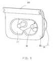
- FIG. 1is an isometric view of an embodiment of a power supply plug structure.
- FIG. 2is similar to FIG. 1 , but viewed from another aspect.
- FIG. 3is an exploded, isometric view of power supply plug structure of FIG. 2 .
- FIG. 4shows a cross-sectional view of the FIG. 2 along the direction of IV-IV.
- the power supply plug structure 100includes a housing 10 , two conductive poles 30 and two wire connecting members 50 , and two snap rings 70 or cir-clips.
- the two conductive poles 30are detachably and individually positioned in the housing 10 and portions of the two conductive poles 30 are exposed out of the housing 10 .
- the wire connecting members 50sleeve on the conductive poles 30 out of the housing 10 .
- Each snap ring 70is clipped onto one conductive pole 30 , and positioned adjacent to the wire connecting member 50 away from the housing 10 for fixing both the conductive pole 30 and the wire connecting member 50 to the housing 10 .
- the housing 10is made of insulating materials, such as plastic.
- the housing 10includes a base body 11 and an extending portion 15 extending outwardly from an end of the base body 11 .
- the base body 11is substantially a hollow cylindrical structure which defines an opening 17 .
- the base body 11includes an outer end surface 111 , and an inner surface 112 opposite to the outer end surface 111 .
- the extending portion 15forms a frame for the base body 11 , such that the base body 11 and the extending portion 15 cooperatively define the opening 17 .
- Two stepped connecting holes 116are defined at a distance from each other through the outer end surface 111 and the inner surface 112 .
- Each stepped connecting hole 116includes a positioning part 1161 and a mounting part 1163 communicating with the positioning part 1161 .
- the positioning part 1161is substantially a tapered hole located adjacent to the outer end surface 111 .
- the positioning part 1161has an increasing hole diameter going from the outer end surface 111 to the inner surface 112 .
- the mounting part 1163is substantially a cylindrical hole adjacent to the inner surface 112 . A diameter of the mounting part 1163 is greater than that of the positioning part 1161 .
- the base body 11further includes a partition block 113 , two first resisting blocks 114 , and two second resisting blocks 115 .
- the first and second resisting blocks 114 and 115function as rails or guides for the snap rings 70 .
- the partition block 113is substantially a barrier strip, which protrudes out from the outer end surface 111 between the two stepped connecting holes 116 .
- the first resisting blocks 114are positioned on the outer end surface 111 .
- Each first resisting block 114is positioned in between one connecting hole 116 and the partition block 113 .
- Two second resisting blocks 115are further formed on opposite ends of the outer end surface 111 .
- Each stepped connecting hole 116is also positioned between one first resisting block 114 and one second resisting block 115 .
- Each conductive pole 30passes through one connecting hole 116 and extends into the opening 17 of the housing 10 .
- the conductive poles 30are made of conductive metal.
- Each conductive pole 30is substantially cylindrical, and includes a main body 31 and an insertion body 33 connecting with the main body 31 .
- the main body 31includes a clamping portion 313 , a contacting portion 315 , a guiding portion 317 and a loading portion 319 connected in that order.
- the clamping portion 313 , the contacting portion 315 , the guiding portion 317 and the loading portion 319 of the main body 31are coaxial with the insertion body 33 .
- the clamping portion 313is positioned at one end of the main body 31 away from the insertion body 33 .
- An annular clamping groove 3131is formed on the clamping portion 313 adjacent to the contacting portion 315 to receive one snap ring 70 .
- the contacting portion 315is substantially cylindrical, and is located between the clamping portion 313 and the guiding portion 317 .
- the guiding portion 317is received in the positioning part 1161 of the connecting hole 116 .
- the guiding portion 317is substantially conical in cross-section, to correspond to the shape of the positioning part 1161 , but with a smaller axial length than that of the positioning part 1161 to avoid the wire connecting member 50 from standing proud of the outer end surface 111 .
- a diameter of the guiding portion 317is increased going from an end of the guiding portion 317 adjacent to the contacting portion 315 to the other end of the guiding portion 317 adjacent to the loading portion 319 .
- the loading portion 319is located adjacent to the insertion body 33 , and received in the mounting part 1163 of the connecting hole 116 .
- the loading portion 319is substantially a cylinder corresponding to the shape of the mounting part 1163 .
- the insertion body 33is connected with one end of the loading portion 319 away from the guiding portion 317 for insertion into a power socket (not shown) or for connecting with another plug to supply power.
- Each wire connecting member 50sleeves on a contacting portion 315 for electrically connecting a wire (not shown) to the conductive pole 30 .
- the wire connecting member 50is a shaped conductive metal piece, and includes a fixing portion 51 and a wire connecting portion 53 connecting with the fixing portion 51 .
- the fixing portion 51is substantially flat.
- a penetrating hole 513is defined through a center of the fixing portion 51 .
- the fixing portion 51sleeves on the contacting portion 315 via the penetrating hole 513 , and is positioned between the first resisting block 114 and second resisting block 115 .
- a bottom surface (not labeled) of the fixing portion 51abuts against the outer end surface 111 .
- the wire connecting portion 53extends upward from one end of the fixing portion 51 .
- a wiring hole 531is formed at a center of the wire connecting portion 53 for insertion of the wire.
- Each snap ring 70sleeves on the clamping portion 313 above the fixing portion 51 , and is engaged in the clamping groove 3131 .
- the open portion of the snap ring 70is a clamping opening 71 for the snap ring 70 .
- the snap ring 70engages in the clamping groove 3131 via a slight and resilient deformation of the clamping opening 71 .
- Two projections 73are formed on a surface of the snap ring 70 facing towards the outer end surface 111 and distanced from the clamping opening 71 .
- the projections 73eliminate loose spacing in between the fixing portion 51 and the snap ring 70 , and the snap ring 70 is thus held firmly in place after assembly thereof.
- the number of the projections 73is not limited to just two; it may be three or more.
- the main bodies 31 of the conductive poles 30are inserted into the connecting holes 116 from the opening 17 , and the insertion bodies 33 are received in the housing 10 .
- the loading portion 319is received in the mounting part 1163
- the guiding portion 317is received in the positioning part 1161 .
- the contacting portion 315 and the clamping portion 313are exposed out of the housing 10 .
- the wire connecting members 50are sleeved on the contacting portions 315 .
- Each snap ring 70sleeves on a clamping portion 313 and engages with the clamping groove 3131 . Two wires are finally connected to the wire connecting portions 53 .
- the power supply plug 100is inserted into a power socket (not shown), and then the wire connecting member 50 is electrically connected to the conductive pole 30 .
- the conductive poles 30 and the wire connecting members 50are detachably positioned on the housing 10 via the snap rings 70 .
- the conductive poles 30 , the wire connecting members 50 and the housing 10can be used again even after damage is done to the power supply plug structure 100 or one of its components.
- the usage ratio of the various components of the power supply plug structure 100is improved. Appearance of the power supply plug structure 100 will not be affected because neither a soldering nor hot melt process is being carried out on the power supply plug structure 100 .
- the structure and the shape of the guiding portion 317correspond to that of the positioning part 1161 , thus the guiding portion 317 will engage in the positioning part 1161 fittingly. There are no spaces found between the conductive poles 30 and the housing 10 .
- the axial length of the guiding portion 317is less than the axial length of the positioning part 1161 to ensure that the wire connecting member 50 is virtually flush.
- the number of the conductive poles 30may be three, and the number of the wire connecting members 50 and the snap rings 70 will be changed correspondingly.
- the positioning part 1161can be omitted, then the guiding portion 317 can be omitted; or the mounting part 1163 can be omitted, and then the loading portion 319 can be omitted.
- the partition block 113 , the two first resisting blocks 114 and the two second resisting blocks 115can be omitted.
- the snap ring 70may be designed to be a full ring, without any circumferential opening, and then the snap ring 70 can be clamped by the clamping portion 313 directly.
- the extending portion 15 of the housing 10can be omitted.
Landscapes
- Details Of Connecting Devices For Male And Female Coupling (AREA)
- Connector Housings Or Holding Contact Members (AREA)
Abstract
Description
Claims (14)
Applications Claiming Priority (3)
| Application Number | Priority Date | Filing Date | Title |
|---|---|---|---|
| CN201110447066.1ACN103187646B (en) | 2011-12-28 | 2011-12-28 | Power supply bolt structure |
| CN201110447066.1 | 2011-12-28 | ||
| CN201110447066 | 2011-12-28 |
Publications (2)
| Publication Number | Publication Date |
|---|---|
| US20130171883A1 US20130171883A1 (en) | 2013-07-04 |
| US8905796B2true US8905796B2 (en) | 2014-12-09 |
Family
ID=48678703
Family Applications (1)
| Application Number | Title | Priority Date | Filing Date |
|---|---|---|---|
| US13/632,299Expired - Fee RelatedUS8905796B2 (en) | 2011-12-28 | 2012-10-01 | Power supply plug structure |
Country Status (3)
| Country | Link |
|---|---|
| US (1) | US8905796B2 (en) |
| CN (1) | CN103187646B (en) |
| TW (1) | TWI442638B (en) |
Cited By (1)
| Publication number | Priority date | Publication date | Assignee | Title |
|---|---|---|---|---|
| US20190181596A1 (en)* | 2015-12-23 | 2019-06-13 | Amphenol Tuchel Electronics Gmbh | Multi-functional connnection assembly having an eccentrically arranged contact pin |
Families Citing this family (1)
| Publication number | Priority date | Publication date | Assignee | Title |
|---|---|---|---|---|
| CN103187646B (en)* | 2011-12-28 | 2015-05-27 | 富泰华工业(深圳)有限公司 | Power supply bolt structure |
Citations (12)
| Publication number | Priority date | Publication date | Assignee | Title |
|---|---|---|---|---|
| US3714617A (en)* | 1971-09-28 | 1973-01-30 | Bendix Corp | Snap in polarizing member for electrical connectors |
| US5194010A (en)* | 1992-01-22 | 1993-03-16 | Molex Incorporated | Surface mount electrical connector assembly |
| US5530205A (en)* | 1994-07-29 | 1996-06-25 | Eaton Corporation | Apparatus for securing bus bars to switches in alternative positions |
| US6705875B2 (en)* | 2001-03-29 | 2004-03-16 | Harting Kgaa | Coaxial plug member |
| US7097516B2 (en)* | 2003-07-21 | 2006-08-29 | Tyco Electronics Amp Gmbh | Connecting box for a solar panel and solar panel |
| TW200828700A (en) | 2006-12-27 | 2008-07-01 | Hon Hai Prec Ind Co Ltd | Electrical connector |
| US7438589B1 (en)* | 2007-08-02 | 2008-10-21 | Phillips & Temro Industries Inc. | Dual entry connector having an integrated power indicator light |
| CN201365041Y (en) | 2009-02-16 | 2009-12-16 | 百容电子股份有限公司 | Power supply socket |
| US20130171883A1 (en)* | 2011-12-28 | 2013-07-04 | Zhi-Hua Liu | Power supply plug structure |
| US8491332B1 (en)* | 2012-01-26 | 2013-07-23 | Volex Plc | Slim C5/C6 coupler |
| US20130288543A1 (en)* | 2010-12-22 | 2013-10-31 | Japan Aviation Electronics Industry, Limited | Connector |
| US20140030932A1 (en)* | 2012-07-27 | 2014-01-30 | Riidea International Corp | Electrical power connector |
Family Cites Families (4)
| Publication number | Priority date | Publication date | Assignee | Title |
|---|---|---|---|---|
| CN2384337Y (en)* | 1999-06-30 | 2000-06-21 | 张永昌 | DC safety socket |
| CN2383246Y (en)* | 1999-08-03 | 2000-06-14 | 张永昌 | Safety socket |
| JP4398079B2 (en)* | 2000-09-06 | 2010-01-13 | モレックス インコーポレイテド | Board connector |
| TW200917592A (en)* | 2007-10-05 | 2009-04-16 | Delta Electronics Inc | Filter and housing thereof |
- 2011
- 2011-12-28CNCN201110447066.1Apatent/CN103187646B/enactiveActive
- 2012
- 2012-01-03TWTW101100124Apatent/TWI442638B/ennot_activeIP Right Cessation
- 2012-10-01USUS13/632,299patent/US8905796B2/ennot_activeExpired - Fee Related
Patent Citations (12)
| Publication number | Priority date | Publication date | Assignee | Title |
|---|---|---|---|---|
| US3714617A (en)* | 1971-09-28 | 1973-01-30 | Bendix Corp | Snap in polarizing member for electrical connectors |
| US5194010A (en)* | 1992-01-22 | 1993-03-16 | Molex Incorporated | Surface mount electrical connector assembly |
| US5530205A (en)* | 1994-07-29 | 1996-06-25 | Eaton Corporation | Apparatus for securing bus bars to switches in alternative positions |
| US6705875B2 (en)* | 2001-03-29 | 2004-03-16 | Harting Kgaa | Coaxial plug member |
| US7097516B2 (en)* | 2003-07-21 | 2006-08-29 | Tyco Electronics Amp Gmbh | Connecting box for a solar panel and solar panel |
| TW200828700A (en) | 2006-12-27 | 2008-07-01 | Hon Hai Prec Ind Co Ltd | Electrical connector |
| US7438589B1 (en)* | 2007-08-02 | 2008-10-21 | Phillips & Temro Industries Inc. | Dual entry connector having an integrated power indicator light |
| CN201365041Y (en) | 2009-02-16 | 2009-12-16 | 百容电子股份有限公司 | Power supply socket |
| US20130288543A1 (en)* | 2010-12-22 | 2013-10-31 | Japan Aviation Electronics Industry, Limited | Connector |
| US20130171883A1 (en)* | 2011-12-28 | 2013-07-04 | Zhi-Hua Liu | Power supply plug structure |
| US8491332B1 (en)* | 2012-01-26 | 2013-07-23 | Volex Plc | Slim C5/C6 coupler |
| US20140030932A1 (en)* | 2012-07-27 | 2014-01-30 | Riidea International Corp | Electrical power connector |
Cited By (2)
| Publication number | Priority date | Publication date | Assignee | Title |
|---|---|---|---|---|
| US20190181596A1 (en)* | 2015-12-23 | 2019-06-13 | Amphenol Tuchel Electronics Gmbh | Multi-functional connnection assembly having an eccentrically arranged contact pin |
| US10727632B2 (en)* | 2015-12-23 | 2020-07-28 | Amphenol-Tuchel Electronics Gmbh | Multi-functional connection assembly having an eccentrically arranged contact pin |
Also Published As
| Publication number | Publication date |
|---|---|
| CN103187646A (en) | 2013-07-03 |
| TW201328035A (en) | 2013-07-01 |
| TWI442638B (en) | 2014-06-21 |
| US20130171883A1 (en) | 2013-07-04 |
| CN103187646B (en) | 2015-05-27 |
Similar Documents
| Publication | Publication Date | Title |
|---|---|---|
| US9980511B2 (en) | Electronic cigarette, battery rod and atomizer | |
| US10958022B2 (en) | Radio-frequency coaxial cable connector with quick installation | |
| US10045563B2 (en) | Atomizer, power supply, and electronic cigarette having same | |
| EP2985840B1 (en) | Electric connector | |
| US9257857B2 (en) | Cable positioning device and charger using same | |
| US10707610B1 (en) | Adaptor and connector assembly | |
| US9583897B2 (en) | Electrical connection system with annular contact | |
| CN207542466U (en) | Electric connector for socket and plug connector | |
| US9997877B2 (en) | Receptacle with non-conductive retaining pin | |
| CN110867705A (en) | Power supply connector | |
| US8905796B2 (en) | Power supply plug structure | |
| CN201210564Y (en) | Audio plug | |
| US6548761B1 (en) | One-way cable terminal connector | |
| US8366465B2 (en) | Plug apparatus | |
| US9502788B2 (en) | Connector assembly with a conductor assembly partially disposed in a block assembly | |
| US11128081B2 (en) | Easily assembled connector | |
| CN209608020U (en) | A kind of adapter and its connector | |
| US8888523B2 (en) | Extension apparatus for power outlet | |
| CN202196898U (en) | Power supply connecctor | |
| CN215266591U (en) | Wiring terminal of battery module | |
| US10075010B2 (en) | Tablet connection system | |
| KR20180000786U (en) | Portable connector | |
| KR101545567B1 (en) | Rotate type outlet | |
| CN216098526U (en) | Coaxial device mounting jig | |
| CN219937441U (en) | Connectors and connector components |
Legal Events
| Date | Code | Title | Description |
|---|---|---|---|
| AS | Assignment | Owner name:HON HAI PRECISION INDUSTRY CO., LTD., TAIWAN Free format text:ASSIGNMENT OF ASSIGNORS INTEREST;ASSIGNOR:LIU, ZHI-HUA;REEL/FRAME:029053/0523 Effective date:20120928 Owner name:FU TAI HUA INDUSTRY (SHENZHEN) CO., LTD., CHINA Free format text:ASSIGNMENT OF ASSIGNORS INTEREST;ASSIGNOR:LIU, ZHI-HUA;REEL/FRAME:029053/0523 Effective date:20120928 | |
| STCF | Information on status: patent grant | Free format text:PATENTED CASE | |
| MAFP | Maintenance fee payment | Free format text:PAYMENT OF MAINTENANCE FEE, 4TH YEAR, LARGE ENTITY (ORIGINAL EVENT CODE: M1551) Year of fee payment:4 | |
| FEPP | Fee payment procedure | Free format text:MAINTENANCE FEE REMINDER MAILED (ORIGINAL EVENT CODE: REM.); ENTITY STATUS OF PATENT OWNER: LARGE ENTITY | |
| LAPS | Lapse for failure to pay maintenance fees | Free format text:PATENT EXPIRED FOR FAILURE TO PAY MAINTENANCE FEES (ORIGINAL EVENT CODE: EXP.); ENTITY STATUS OF PATENT OWNER: LARGE ENTITY | |
| STCH | Information on status: patent discontinuation | Free format text:PATENT EXPIRED DUE TO NONPAYMENT OF MAINTENANCE FEES UNDER 37 CFR 1.362 | |
| FP | Lapsed due to failure to pay maintenance fee | Effective date:20221209 |