US8904886B1 - Devices for obtaining cylinder samples of natural gas or process gas and methods therefore - Google Patents
Devices for obtaining cylinder samples of natural gas or process gas and methods thereforeDownload PDFInfo
- Publication number
- US8904886B1 US8904886B1US12/968,017US96801710AUS8904886B1US 8904886 B1US8904886 B1US 8904886B1US 96801710 AUS96801710 AUS 96801710AUS 8904886 B1US8904886 B1US 8904886B1
- Authority
- US
- United States
- Prior art keywords
- sample
- cap
- cylinder
- housing
- cavity
- Prior art date
- Legal status (The legal status is an assumption and is not a legal conclusion. Google has not performed a legal analysis and makes no representation as to the accuracy of the status listed.)
- Expired - Fee Related, expires
Links
Images


Classifications
- G—PHYSICS
- G01—MEASURING; TESTING
- G01N—INVESTIGATING OR ANALYSING MATERIALS BY DETERMINING THEIR CHEMICAL OR PHYSICAL PROPERTIES
- G01N1/00—Sampling; Preparing specimens for investigation
- G01N1/02—Devices for withdrawing samples
- G01N1/22—Devices for withdrawing samples in the gaseous state
- G01N1/2247—Sampling from a flowing stream of gas
- G—PHYSICS
- G01—MEASURING; TESTING
- G01N—INVESTIGATING OR ANALYSING MATERIALS BY DETERMINING THEIR CHEMICAL OR PHYSICAL PROPERTIES
- G01N1/00—Sampling; Preparing specimens for investigation
- G01N1/02—Devices for withdrawing samples
- G01N1/10—Devices for withdrawing samples in the liquid or fluent state
- G01N1/20—Devices for withdrawing samples in the liquid or fluent state for flowing or falling materials
- G01N1/2035—Devices for withdrawing samples in the liquid or fluent state for flowing or falling materials by deviating part of a fluid stream, e.g. by drawing-off or tapping
- G01N1/2042—Devices for withdrawing samples in the liquid or fluent state for flowing or falling materials by deviating part of a fluid stream, e.g. by drawing-off or tapping using a piston actuated by the pressure of the liquid to be sampled
- G—PHYSICS
- G01—MEASURING; TESTING
- G01N—INVESTIGATING OR ANALYSING MATERIALS BY DETERMINING THEIR CHEMICAL OR PHYSICAL PROPERTIES
- G01N1/00—Sampling; Preparing specimens for investigation
- G01N1/02—Devices for withdrawing samples
- G01N1/10—Devices for withdrawing samples in the liquid or fluent state
- G01N2001/1031—Sampling from special places
- G01N2001/105—Sampling from special places from high-pressure reactors or lines
- G—PHYSICS
- G01—MEASURING; TESTING
- G01N—INVESTIGATING OR ANALYSING MATERIALS BY DETERMINING THEIR CHEMICAL OR PHYSICAL PROPERTIES
- G01N1/00—Sampling; Preparing specimens for investigation
- G01N1/02—Devices for withdrawing samples
- G01N1/10—Devices for withdrawing samples in the liquid or fluent state
- G01N1/20—Devices for withdrawing samples in the liquid or fluent state for flowing or falling materials
- G01N1/2035—Devices for withdrawing samples in the liquid or fluent state for flowing or falling materials by deviating part of a fluid stream, e.g. by drawing-off or tapping
- G01N2001/2071—Removable sample bottle
- G—PHYSICS
- G01—MEASURING; TESTING
- G01N—INVESTIGATING OR ANALYSING MATERIALS BY DETERMINING THEIR CHEMICAL OR PHYSICAL PROPERTIES
- G01N1/00—Sampling; Preparing specimens for investigation
- G01N1/02—Devices for withdrawing samples
- G01N1/22—Devices for withdrawing samples in the gaseous state
- G01N1/2226—Sampling from a closed space, e.g. food package, head space
- G01N2001/2238—Sampling from a closed space, e.g. food package, head space the gas being compressed or pressurized
Definitions
- the present inventionrelates to spot fluid sampling systems.
- a “moveable end” (ME) fluid sampling systemwhich employs a method of collection wherein the initial cylinder volume of the collection vessel or sampling cylinder is zero.
- a spot sample cylinderis inserted into the pressurized fluid source, said sample cylinder employing a piston or moveable end to configured to initially be situated in a position wherein the sample cavity has no volume so as to dispense with the necessity of purging same, the moveable end formed to reposition as the sample cavity is filled, thereby expanding the cavity upon sampling.
- the present inventionalso relates to a new and unique cap/body (CB) sample cylinder system having a size and design to enable it to be inserted into a pressurized process with an insertion device.
- the capfunctions as a fill/empty valve.
- the cap and body of the cylinderare designed to eliminate the necessity of purging the sample pathway.
- the sample cylinder's internal cavityit may be evacuated by pulling a deep vacuum and/or filling with a diluent gas that cannot be detected by the analyzer which will analyze the sampled fluid.
- the CB cap to body sealdoes not require the normally employed sealing materials such as elastomers or plastics.
- the cap and bodyare preferably constructed of metal, and when assembled are formed to provide a metal to metal seal to retain pressurized fluids in the internal cavity of the sample cylinder.
- a unique housing and method for evacuating the sample gas from the CB sample cylinderis also provided.
- a “spot” sampleis taken periodically, or a composite sample is taken over a period of time.
- a “spot sample”generally consists of extracting a sample of the gas at a “spot”, or single point in time.
- a composite sampleis generally taken by a sampling apparatus (composite sampler) which extracts a small volume (bite) of gas sample periodically, which is collected in a sample cylinder.
- a typical composite samplerwill control the sampling interval based on time or flow volume. Flow volume information, or electric pulse, is usually provided by an external flow computer.
- a typical composite collection periodis 30 days.
- sample cylindersutilized for spot and composite sampling. They are the constant volume and constant pressure types of sample cylinder. Constant pressure types of sample cylinders are of the floating piston or bladder (bag) type.
- Gas Processors Association Standard Publication 2166 entitled “Obtaining natural Gas Samples for Analysis by Gas Chromatography”details several spot sampling methods in its 1986 revision and its draft.
- the main thrust of the GPA 2166 standarddeals with methods for purging the sample cylinder, dealing with entrained liquid using the GPA or other type separator, and prevention of condensation of gas components.
- HCDPThydrocarbon dew point temperature
- API 14.1The hydrocarbon dew point temperature
- 141.6here the standard calls out issues which need to be addressed when sampling natural gas. Issues include ambient temperature condition and phase-change characteristics.
- 14.1.6.6it makes clear that no part of the spot sampling system should be allowed to fall below the HCDPT, otherwise biased analytical results and non-representative samples are likely to result. Maintaining the sample system at, or above, the HCDPT is recommended.
- the entire API 14.1-2004 documentis rich in thermodynamic and practical information.
- Appendix A“The Phase Diagram” and A.1 phase changes in general.
- K. A. Behring, Flomeko '98, the 9th Int Conf on Flow Measurement, Lund, Sweden(Jun. 15-17, 1998), one can conclude that condensation of portion of a gas phase and/or vaporization of a liquid wherein the resulting vapor becomes intermixed with the gas phase will likely (almost certainly) result in product composition changes in the gas phase.
- the present inventionovercomes the expense and reliability problems associated with prior art spot sampling techniques in the above scenarios by inserting the sample cylinder of the present invention inside of the pressurized containment vessel or pipeline when taking a sample.
- a spot sample cylinderis inserted into the pressurized gas (or fluid) source, said sample cylinder referenced as an M.E. sample cylinder, as it has a movable end (M.E.) which allows the volume of the cylinder to be dynamically adjustable.
- M.E.movable end
- a “zero volume sample cavity”such as the M.E. sample cylinder (or any other zero volume sample cavity configuration) can eliminate the need for purging the cylinder. This is important as cylinder purging represents one of the largest and most frequent sources of analytical error in the sampling of natural gas.
- a second embodiment of the invention(ex. FIG. 2A ) is provided which contemplates a new and unique cap/body (CB) sample cylinder which is evacuated via a specially designed housing prior to the sampling, such that the initial cylinder volume of the sampling cylinder (or other collection container) is made effectively zero, thereby eliminating the requirement of using prior art cylinder purging techniques which may be prone to altering the sample fluid composition.
- CBcap/body
- An alternative to fully evacuating the CB sample cylinderis to purge said cylinder before sample collection with a diluent gas, such as helium, which cannot be detected by the sample fluid analyzer.
- a diluent gassuch as helium
- Still another technique of the present inventionis to first purge the CB sample cylinder with a diluent gas which cannot be detected by the sample fluid analyzer, followed by reducing the diluent gas pressure in the cylinder to essentially zero by evacuation.
- the capis sealed to the CB sample cylinder body after purging and/or evacuation of the internal cylinders cavity, preferably while utilizing a custom housing for that purpose, also disclosed in the present application.
- Purging of the interconnecting tubing/piping and sample cylinderis the greatest source of error in spot sampling.
- the present inventioneliminates this source of error.
- the present inventioncan also be filled external to the source fluid. Due to its design, the sample path from the source of fluid to the cylinder is minimized, thereby limiting the exposure to ambient temperature during the sampling process.
- FIG. 1Ais a side, a partially cut-away, partially cross-sectional view of an exemplary design for a sample cylinder having a moveable end (M.E. Sample Cylinder) for use in the present invention, wherein the moveable end is shown at the first end of the sample cavity.
- M.E. Sample Cylindermoveable end
- FIG. 1Bis a side, partially cut-away, partially cross-sectional view of the device of FIG. 1A , wherein the moveable end is shown at the second end of the sample cavity.
- FIG. 2Ais a side, partially cut-away, partially cross sectional view of the cap/body (CB) sample cylinder embodiment of the invention configured for evacuation to zero volume prior to sampling via placement into the fluid process (at prevailing pressure and temperature of the fluid stream), or alternatively filled with a residual gas not which would not interfere with the analysis of the fluid stream being sampled prior to sampling, with a cap shown in the closed, sealed position.
- CBcap/body
- FIG. 2Bis a side, partially cut-away, partially cross-sectional view of the CB sample cylinder of FIG. 2A , illustrating the cap separated from the body and showing the positions of the cap sealing surface ( 7 ) and body sealing surface ( 8 ).
- FIG. 3is a partial, close-up, side, partially cut-away, partially cross-sectional view of the CB sample cylinder of FIG. 2A , illustrating the cap engaging the body in a closed, sealed position, illustrating the threaded engagement therein, as well as engagement of the cap sealing surface ( 7 ) to the body sealing surface ( 8 ).
- FIG. 4illustrates the sample cylinder of FIG. 2A engaged to housing 14 A, with sealing O rings ( 15 a and 15 b ) situated juxtaposed either side of the engagement of the CB sample cylinder cap and body formed so as to allow the evacuation of the volume of the sample cylinder, as will be further explained herein.
- FIG. 5is a top view of the cap of FIG. 2A illustrating the position of an slot formed on its upper surface, and pins longitudinally aligned therewith, and emanating from the diameter therefrom.
- FIG. 6illustrates a side, cut-away view of the invention of FIG. 2A , wherein the pins of FIG. 5 are situated in slits formed in the housing as the body and cap forming the CB sample cylinder are placed in the housing, so as to lock the cap in position so that the body of the cylinder can be rotated along its axis (such as with a screwdriver or the like) to unseal the cap from the body and allow the evacuation of the volume of the sample cylinder via passage 18 .
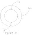
- FIG. 6Ais a top view of the housing of FIG. 6 , illustrating the pin slots 19 , 19 ′ formed therein.
- FIG. 6Bis a cross-sectional view of the top of the housing of FIG. 6 .
- the first embodiment of the sample cylinder of the present inventionis shown in FIGS. 1A and 1B .
- the moveable end (ME) sample cylinder 28is comprised of a cylinder wall 33 , having a mechanical end stop 34 at a first end 37 , valve seat 32 at a second end 38 , valve stem/poppet 31 mounted to threaded plug 30 ′, movable end 35 , seal 36 , Hex recess 30 , sample cavity 29 , and valve 40 formed by valve stem/poppet 31 and valve seat 32 situated in valve chamber 42 .
- Fluid flow passages 41 A, 41 Ballow fluid from into valve chamber 42 .
- valve chamber 42has an inner wall forming a threaded connection for threadingly engaging threaded plug 30 ′ having first 70 and second 70 ′ ends, the first end 70 having hex recess 30 formed therein, the second end 70 ′ having valve stem/poppet 31 engaged thereto.
- moveable end 35is at first end 37 against mechanical stop 34 and valve stem/poppet 31 is retracted from valve seat 32 .
- sample cavity 29is at its maximum volume and valve 40 is opened.
- sample cavity 29is at its minimum volume or essentially zero volume.
- the sample cavityprovides a variable volume dependent upon the location of the mechanical stop relative to the first 37 and second 38 ends.
- This moveable end (ME) sample cylindermay be inserted into a pressurized fluid source for obtaining a sample by a number of means.
- One such meansutilizes a packing gland or dynamic pressure seal type of insertion device, similar to that used for insertion of probes, sensors, corrosion coupons etc.
- a second type of insertion means to insert the ME sample cylinder into a pressurized processutilizes a pressure balance approach similar to that described in U.S. Pat. No. 7,472,615 by Mayeaux entitled “Portable Insertable Probe assembly”, the contents of which are incorporated herein by reference.
- Threaded plug 30 ′may then be turned 72 in a first direction via hex recess 30 to open 73 valve 40 (as in FIG. 1A ), so as to allow fluid from the pressurized fluid source to migrate through 74 passages 41 A, 41 B into valve chamber 42 , through the open 73 valve, and into 74 A sample cavity 29 , where moveable end 35 ( FIG. 1B ) is slidingly urged 75 from the second end 38 to the first end 37 via pressure from the fluid entering the sample cavity 29 , filling sample cavity with fluid, as movable end 35 migrates to the first end 37 .
- the threaded plug 30may be turned 72 ′ a second direction via hex recess 30 to close 73 ′ valve 40 , capturing and retaining the fluid in the sample cavity, thereby providing a filled sample cylinder, which may be then removed 71 ′ from the pressurized fluid source for analysis or other purpose.
- a method of using the ME sample cylinder of the present inventionmay thereby be summarized as follows:
- a sample cylinder or other sample containermay be evacuated prior to use to insure non-contamination of the sample cavity.
- evacuation of the sample cylinder prior to the sampling processeliminates the necessity of a moveable fluid barrier to selectively provide zero volume in the exemplary method illustrated in steps a-h, above.
- An alternative to evacuationcould comprise the utilization of an inert gas, such as helium or the like, which could be provided at a pressure less than the process fluid to prevent contamination prior to sampling.
- FIGS. 2A-6BThe present concept of spot sampling using a pre-evacuated sample cylinder is detailed in FIGS. 2A-6B .
- FIGS. 2A , 2 B and 3provide an overview of the contemplated sample cylinder (referenced as cap/body (CB) sample cylinder), and are referenced in the following discussion.
- the CB sample cylinder 1is comprised of a cap 2 and a body 3 .
- cap threads 10are threadly engaged 10 ′ fully to body threads 9
- the cap seal 8 surface and body seal 7 surfaceengage to form a closed valve 20 , so as to isolate cavity 6 from ambient and form a container for any fluids therein.
- body seal 7 surface and cap seal 8 surfaceare separated 21 ′ from one another other, forming a space therebetween to allow fluid passage into 22 and out 22 ′ of cavity 6 via a fluid pathway which passes between separated body seal 7 surface and cap seal 8 surface, as well as the space forming the groove 13 between the body and cap.
- Body and cap threads 9 , 10in the present embodiment preferably have a tolerance relative one another so as to facilitate the passage of pressurized fluid therebetween when loosened so that the cap need not be fully removed from the body for the passage to occur, with fluid passage preferably possible upon separation of the cap seal 8 from the body seal 7 .
- housing 14 Afor evacuating the sample cylinders, as well as collecting the sample therefrom.
- Housing 14 Ahas a side wall 80 forming a longitudinally oriented receiver 80 ′ having inner surface 82 forming an inner diameter 81 , the receiver 80 ′ formed to receive the outer diameter 81 ′ of CB sample cylinder 1 and cap 2 , with the inner surface 82 of the receiver 80 ′ in housing 14 A, (preferably) effectively enveloping the length 83 of the sample cylinder.
- the housingby way of the receiver to be used to isolate the junction of cap 8 and body 7 at groove 13 , via O-rings 15 A, 15 B situated on opposing sides of groove 13 , the O-rings spanning the ID 81 of receiver 80 ′ and the OD 81 ′ of sample cylinder, sealing same so as to form a containment zone 13 ′ between said O-Rings 15 A, 15 B, containing the area to direct the passage of fluids into 22 or out of 22 ′ sample cavity 6 via port 18 .
- slot 4 ais engaged with stationary flat blade 17 and groove 13 is isolated from the ambient via seals 23 ′, 23 ′′ formed by opposing O rings 15 a and 15 b , each engaging inner surface 82 of housing and outer surface 81 ′′ of CB sample cylinder, respectively, so as to allow cavity 6 to be evacuated, or filled with diluting, non-detectable gas, or emptied of its contained sample via threaded port 18 , when cap threads 10 and body threads 9 are loosened 24 by use of a flat bladed screwdriver 16 engaged with slot 4 b , so as to separate cap seal 8 from body seal 7 , to allow the passage 84 of fluid therebetween.
- sampling cylinderor “micro cylinder” is not intended to limit the structure to sampling, or containers which may be used for other purposes, such as collection and storage. Accordingly, the terms “sampling cylinder”, “micro cylinder” or the like should be considered in the present disclosure as synonymous with storage cylinder, collection cylinder, or like devices.
- the CB sample cylinderis placed into the housing 14 a , the cap 2 is loosened from the body 3 , again separating the body seal 7 from the cap seal 8 , allowing the passage of the sample from the sample cylinder, and through threaded port 18 for analysis, storage, further processing, etc.
- the CB sample cylinderhaving no contaminates in its sample cavity by virtue of lowering the pressure to essentially zero or having residual gas which cannot be detected by the sample fluid analyzer, at the beginning of a sampling procedure, and eliminating liquids and particles from the sample gas entering the sample cylinder, the three largest sources of error in spot sampling are eliminated.
- phase separation membraneBy providing a phase separation membrane during sampling, and allowing the sample gas to flow through a phase separation membrane designed to reject liquids (all types) and particles before entering the sample cylinder, entrained liquids are eliminated.
- the separated liquidcan either be drained back into the pressurized process, or captured for analysis or the like.
- Having a near zero cylinder volume or undetectable diluent gas in the sample cavitycan eliminate the need for purging the cylinder, which said cylinder purging represents one of the largest and most frequent sources of analytical error in the sampling of natural gas. Insertion of the ME or CB sample cylinder into a pressurized fluid process utilizing the dynamic sealing and pressure equalization can be accomplished with sample probes or the like.
- FIGS. 5 , 6 , and 6 A- 6 BAnother option for opening and closing the valve formed by body sealing surfaces 7 and cap sealing surface 8 when the sample cylinder is in the housing is accomplished with the alternative design housing 14 b , FIGS. 5 , 6 , and 6 A- 6 B.
- Pin 5having opposing ends 5 ′, 5 ′′ engaged 24 in pin slots 19 , 19 ′′, respectively, to prevent cap 2 from rotating within housing 14 b.
- Flat blade screwdriver 16 engaged 24 ′ in slot 4 apermits rotation 24 ′′ of the body 3 to facilitate the opening 24 A and closing 24 B of valve 20 formed by sealing surface 7 and sealing surface 8 , respectively.
- This embodimentis different in that the body is turned relative to the cap, as opposed to the cap being turned relative to the body (shown in the embodiment of FIGS. 2A-5 ), but otherwise, the method of preparation of the sample cylinder for testing, the testing procedure, and the procedure for removal of the sample from the cylinder is the same as that discussed in the embodiment of housing 14 A.
- An example of a method of sampling utilizing the apparatus of the present inventionmay comprise the steps, for example, of:
- A. Providing a sample containercomprising: A body therein a sample cavity, said body being formed so as to be immersed into a pressurized fluid process, and having threads and a sealing surface, a threaded cap with metal sealing surfaces being formed so as to mate with said threaded section and sealing surface of said body;
- the housing 14 A (or 14 B, FIG. 6 ) of the present inventionmay be utilized to prepare the sample cylinder prior to testing by placing the sample cylinder into the receiver, loosening the threads of the cap and body to separate the seals therebetween, so as to allow the flow of fluid therebetween.
- a vacuummay then be established via port 18 so as to evacuate containment zone 13 ′, and, with the seals 7 , 8 separated, fluid in the cavity 6 of sample cylinder flows therefrom due to pressure differential, evacuating same.
- diluent fluidmay be introduced via pressurized flow through port 18 to flow into cavity 6 to urge contaminants from said cavity 6 , or a combination of diluent fluid and evacuation may be used.
- a second portmay be provided through sidewall 80 of housing, communicating with said containment zone 13 ′ for egress of diluent fluid in such an operation. Said cap is then tightened to said body so that seals 7 , 8 are engaged, the sample cylinder is removed, then the sample is taken.
- the sample cylindermay be placed into a fluid to be sampled, where it is allowed to reach the temperature of the fluid, then the cap and/or body of the sample cylinder is loosened to separate seals 7 , 8 , so that fluid can flow into cavity 6 for sampling, then the cap is tightened to the body to close seals 7 , 8 , containing the fluid in the cavity for sampling.
- the sample cylindermay then be placed into the housing, the cap loosened relative the body (or visa versa) to separate the seals 7 , 8 , allowing extraction of the fluid therein via containment zone 13 ′ and port 18 .
- CB sample cylinderElement Description 1 CB type sample cylinder 2 Cap 3 Body 4a Slot 4b Slot 5, 5′, 5′′ Pin, pin ends 6 Cavity 7 Body Sealing Surface 8 Cap Sealing Surface 9 Body Female Threads 10 Cap Male Thread, 10′ threads engaged 11 Upper Cap Surface 12 Flat Surface 13 Groove between cap and Body 13′ Containment zone 14 Housing for filling/emptying sample cylinder 15a O Ring 15b O Ring 16 Flat blade screwdriver 17 Flat blade 18 Housing Port 19 Pin Slots 20 Valve 21 Loosened, 21′ moves away/spaced apart 22 Sample migration into cavity, 22′ out of cavity 23, 23′ Sealed 24 loosened 80 side wall of housing 80' receiver 81, ′, ′′ ID receiver, OD sample cylinder, outer surface 82 inner surface receiver 83 length of sample cylinder
Landscapes
- Life Sciences & Earth Sciences (AREA)
- Health & Medical Sciences (AREA)
- General Health & Medical Sciences (AREA)
- Physics & Mathematics (AREA)
- Chemical & Material Sciences (AREA)
- Analytical Chemistry (AREA)
- Biochemistry (AREA)
- General Physics & Mathematics (AREA)
- Immunology (AREA)
- Pathology (AREA)
- Biomedical Technology (AREA)
- Molecular Biology (AREA)
- Engineering & Computer Science (AREA)
- Hydrology & Water Resources (AREA)
- Sampling And Sample Adjustment (AREA)
Abstract
Description
- 1. Gas Processors Association (GPA) standard 2166-1986 and draft copy of 2166-2004 2. API-manual of Petroleum measurement standards chapter 14, section 1, collecting and handling of natural gas samples for custody transfer.
API-14.1 revision 2001 3. Southwest research Institute (SRI) San Antonio, Tex. 4 Accuracy of Natural Gas Sampling Techniques, and the impact of composition measurement errors on Flow Rate and Heating value determination. By K. A. Behring II, Southwest research Institute. Paper presented at Flomeko '98, International conference on flow Measurement, (Lund, Sweden, Jun. 15-17, 1998)
- a. providing a spot sample container, comprising:
- a housing having formed therein a sample cavity having first and second ends, and a wall;
- a moveable end slidingly engaging said wall of said sample cavity, so as to form a moveable fluid barrier within said sample cavity, having a variable volume associated with the position of said moveable barrier;
- a valve associated with said sample cavity;
- b. immersing said container into a pressurized fluid process;
- c. allowing the temperature of said container to adjust to the temperature of said pressurized fluid process;
- d. opening said valve;
- e. allowing fluid from said pressurized fluid process to migrate into said sample cavity;
- f. allowing said moveable stop to slidingly migrate from said first end of said sample cavity to said second end of said sample cavity as said sample cavity fills with fluid;
- g. closing said valve, providing a filled spot sample container; and
- h. removing said filled spot sample container from said pressurized fluid process.
- a. providing a spot sample container, comprising:
| Elements of the CB sample cylinder: |
| Element | Description | ||
| 1 | CB | ||
| 2 | |||
| 3 | |||
| 4a | |||
| 4b | Slot | ||
| 5, 5′, 5″ | Pin, pin ends | ||
| 6 | |||
| 7 | Body Sealing Surface | ||
| 8 | |||
| 9 | |||
| 10 | Cap Male Thread, 10′ threads engaged | ||
| 11 | Upper Cap Surface | ||
| 12 | |||
| 13 | Groove between cap and | ||
| 13′ | Containment zone | ||
| 14 | Housing for filling/emptying | ||
| O Ring | |||
| O Ring | |||
| 16 | |||
| 17 | |||
| 18 | |||
| 19 | |||
| 20 | |||
| 21 | Loosened, 21′ moves away/spaced apart | ||
| 22 | Sample migration into cavity, 22′ out of | ||
| 23, 23′ | Sealed | ||
| 24 | loosened | ||
| 80 | side wall of housing | ||
| 80' | |||
| 81, ′, ″ | ID receiver, OD sample cylinder, | ||
| 82 | |||
| 83 | length of sample cylinder | ||
Claims (10)
Priority Applications (1)
| Application Number | Priority Date | Filing Date | Title |
|---|---|---|---|
| US12/968,017US8904886B1 (en) | 1996-08-22 | 2010-12-14 | Devices for obtaining cylinder samples of natural gas or process gas and methods therefore |
Applications Claiming Priority (11)
| Application Number | Priority Date | Filing Date | Title |
|---|---|---|---|
| US08/701,406US5841036A (en) | 1996-08-22 | 1996-08-22 | Modular sample conditioning system |
| US09/162,239US6357304B1 (en) | 1996-08-22 | 1998-09-28 | System for retrieving a gas phase sample from a gas stream containing entrained liquid, and sample conditioner assembly therefore |
| US22133500P | 2000-07-26 | 2000-07-26 | |
| US09/915,192US6701794B2 (en) | 1996-08-22 | 2001-07-25 | System for retrieving a gas phase sample from a gas stream containing entrained liquid, and sample conditioner assembly therefore |
| US10073602P | 2002-08-02 | 2002-08-02 | |
| US10/408,026US6904816B2 (en) | 1996-08-22 | 2003-04-03 | System for retrieving a gas phase sample from a gas stream containing entrained liquid, and sample conditioner assembly therefore |
| US10/631,501US7225690B1 (en) | 2002-08-02 | 2003-07-31 | Multi-cavity sample cylinder with integrated valving |
| US64631405P | 2005-01-24 | 2005-01-24 | |
| US11/151,018US7481125B2 (en) | 1996-08-22 | 2005-06-13 | Devices for obtaining cylinder samples of natural gas or process gas, and methods therefore |
| US12/344,418US7874221B1 (en) | 1996-08-22 | 2008-12-26 | Devices for obtaining cylinder samples of natural gas or process gas, and methods therefore |
| US12/968,017US8904886B1 (en) | 1996-08-22 | 2010-12-14 | Devices for obtaining cylinder samples of natural gas or process gas and methods therefore |
Related Parent Applications (1)
| Application Number | Title | Priority Date | Filing Date |
|---|---|---|---|
| US12/344,118Continuation-In-PartUS7896253B2 (en) | 2007-12-28 | 2008-12-24 | Method for automatically rectifying business card presentation angle |
Publications (1)
| Publication Number | Publication Date |
|---|---|
| US8904886B1true US8904886B1 (en) | 2014-12-09 |
Family
ID=52003517
Family Applications (1)
| Application Number | Title | Priority Date | Filing Date |
|---|---|---|---|
| US12/968,017Expired - Fee RelatedUS8904886B1 (en) | 1996-08-22 | 2010-12-14 | Devices for obtaining cylinder samples of natural gas or process gas and methods therefore |
Country Status (1)
| Country | Link |
|---|---|
| US (1) | US8904886B1 (en) |
Cited By (4)
| Publication number | Priority date | Publication date | Assignee | Title |
|---|---|---|---|---|
| CN107044927A (en)* | 2017-03-17 | 2017-08-15 | 合肥固泰自动化有限公司 | A kind of sampling probe in coal dust workshop |
| US10222302B1 (en)* | 2014-11-06 | 2019-03-05 | Mayeaux Holding Llc | Cyclonic system for enhanced separation in fluid sample probes and the like |
| BE1025970B1 (en)* | 2018-02-01 | 2019-09-03 | R. DEZWAEF naamloze vennootschap | Apparatus for taking a fluid sample from a tube or reservoir and device equipped therewith |
| US11293841B2 (en)* | 2017-05-21 | 2022-04-05 | Jms Southeast, Inc. | Process inserts, assemblies, and related methods for high velocity applications |
Citations (55)
| Publication number | Priority date | Publication date | Assignee | Title |
|---|---|---|---|---|
| US3203247A (en) | 1962-01-08 | 1965-08-31 | Universal Oil Prod Co | Variable volume sampling chamber |
| US3273647A (en) | 1963-08-19 | 1966-09-20 | Halliburton Co | Combination well testing and treating apparatus |
| US3638499A (en)* | 1968-05-13 | 1972-02-01 | Robert Saint Andre | Device for sampling fluid of hydraulic circuit |
| US3831953A (en) | 1970-01-05 | 1974-08-27 | Parker Hannifin Corp | Solenoid operated valve assembly |
| US3835710A (en) | 1971-05-03 | 1974-09-17 | L Pogorski | Geo-chemical exploration method |
| US3848579A (en) | 1973-02-23 | 1974-11-19 | Real A Villa | Automatic elasto-valvular hypodermic sampling needle |
| US3872721A (en) | 1973-02-28 | 1975-03-25 | Exxon Production Research Co | Downhole gas detector system |
| US4014216A (en) | 1976-03-22 | 1977-03-29 | Joseph Scott Thornton | Apparatus for sampling gas mixtures |
| US4112768A (en) | 1976-09-17 | 1978-09-12 | U.S. Philips Corporation | Device for taking a liquid sample |
| US4157040A (en) | 1975-12-10 | 1979-06-05 | General Electric Company | Apparatus for collecting pyrolysates from a gas-cooled dynamoelectric machine |
| US4175424A (en)* | 1977-07-27 | 1979-11-27 | Societe Nationale Elf Aquitaine (Production) | Device for handling and testing a cell adapted for sampling a pressurized fluid |
| US4269064A (en) | 1979-05-31 | 1981-05-26 | Johnson Julius T | On-line sampler |
| US4346613A (en)* | 1979-11-19 | 1982-08-31 | Turner Robert C | Liquid sample collector device |
| US4402911A (en)* | 1981-07-24 | 1983-09-06 | Phillips Petroleum Company | Apparatus and method for storing gas samples |
| US4459266A (en)* | 1982-01-05 | 1984-07-10 | Lamoreaux Charles L | Air purity monitoring system |
| DE3310032A1 (en) | 1983-03-19 | 1984-09-20 | Dr. H. Tiefenbach Gmbh & Co, 4300 Essen | Immersion syphon for collecting liquid samples, in particular water samples from bodies of water of great depth |
| SU1250251A1 (en) | 1985-01-07 | 1986-08-15 | Казахский Институт Физической Культуры | Apparatus for taking a sample of expired air |
| US4628750A (en) | 1984-09-27 | 1986-12-16 | Welker Engineering Company | Integrated pump and sample vessel |
| US4800763A (en) | 1987-02-03 | 1989-01-31 | Veg-Gasinstituut N.V. | Method of sampling a fluid stream and apparatus suitable therefor |
| US4821585A (en) | 1984-12-12 | 1989-04-18 | Eberhard Kempe | Probe means for sampling volatile components from liquids or gases |
| US4865811A (en) | 1986-07-01 | 1989-09-12 | Biotec Instruments Limited | Apparatus for automatic chemical analysis |
| US4865729A (en)* | 1985-11-04 | 1989-09-12 | Sepragen Corporation | Radial thin layer chromatography |
| SU1520382A1 (en) | 1987-12-01 | 1989-11-07 | Харьковский филиал Всесоюзного научно-исследовательского и проектно-конструкторского института по проблемам освоения нефтяных и газовых ресурсов континентального шельфа | Sampler |
| US4928541A (en) | 1988-02-05 | 1990-05-29 | Solinst Canada Limited | Groundwater sampling apparatus |
| US4974456A (en) | 1988-02-24 | 1990-12-04 | The Dow Chemical Company | Zero head space sampling method |
| US5191801A (en) | 1990-03-20 | 1993-03-09 | Precision General, Inc. | Fluid sampling pump |
| US5205988A (en) | 1989-04-06 | 1993-04-27 | Nihon Bunko Kogyo Kabushiki Kaisha | Apparatus for measuring gaseous aldehyde |
| US5303599A (en) | 1992-07-29 | 1994-04-19 | Welker Engineering Company | Miniaturized sampler |
| JPH06288880A (en) | 1993-04-01 | 1994-10-18 | Marubishi Baioenji:Kk | Sample liquid collection device |
| US5369034A (en)* | 1989-09-08 | 1994-11-29 | Cem Corporation | Use of a ventable rupture diaphragm-protected container for heating contained materials by microwave radiation |
| WO1995002176A1 (en) | 1993-07-08 | 1995-01-19 | Isco, Inc. | Method and apparatus for sampling fluids |
| US5406855A (en) | 1994-05-25 | 1995-04-18 | Welker Engineering Company | Solenoid actuated sampler |
| US5442969A (en) | 1992-10-13 | 1995-08-22 | Baxter International Inc. | Fluid sampling module |
| US5536474A (en) | 1993-06-11 | 1996-07-16 | Institut Francais Du Petrole | System for transferring samples under pressure |
| US5637792A (en) | 1994-12-08 | 1997-06-10 | Sanshin Kogyo Kabushiki Kaisha | Exhaust gas sampler |
| US5677478A (en)* | 1996-05-03 | 1997-10-14 | Fann Instrument Company | Pressure relief system for filtration testing apparatus |
| US5794695A (en) | 1996-08-02 | 1998-08-18 | Peterson; Roger | Method and apparatus for gathering and preparing liquid samples for analysis |
| US5814741A (en) | 1996-03-01 | 1998-09-29 | American Air Liquide Inc. | Metal sampling method and system for non-hydrolyzable gases |
| US5844123A (en) | 1994-06-01 | 1998-12-01 | Marsh; Robert Anthony | Gas sensing system |
| US5899349A (en)* | 1997-10-02 | 1999-05-04 | Beckman Instruments, Inc. | Cap/closure having a venting mechanism for use with centrifuge containers |
| US6021661A (en)* | 1998-05-18 | 2000-02-08 | Quantachrome Corporation | Apparatus for determining pore volume distribution of multiple samples by intrusion of a non-wetting liquid |
| US6354345B1 (en) | 1990-02-02 | 2002-03-12 | Isco, Inc. | Pumping system |
| US6405580B2 (en) | 2000-05-08 | 2002-06-18 | The United States Of America As Represented By The Secretary Of The Navy | Apparatus for detecting and measuring foam forming compounds in aqueous solutions |
| US20030033858A1 (en) | 2001-08-17 | 2003-02-20 | Lambert David K. | Fuel volatility sensor and method based on capacitance measurement |
| US20030051565A1 (en) | 2001-09-17 | 2003-03-20 | Nimberger Spencer M. | Heated enclosure purge system |
| US6539312B1 (en) | 2000-09-18 | 2003-03-25 | Pgi International, Inc. | Sampling system for obtaining pipeline gas samples |
| US20030089526A1 (en) | 2000-05-10 | 2003-05-15 | Beeker Arnoldus Emanuel Ruthgerus | Grondmonsternemer |
| US20030103551A1 (en) | 2001-11-30 | 2003-06-05 | Sammy Haddad | Method of predicting formation temperature |
| US6659177B2 (en) | 2000-11-14 | 2003-12-09 | Schlumberger Technology Corporation | Reduced contamination sampling |
| US6675664B1 (en) | 2001-12-13 | 2004-01-13 | Itt Manufacuring Enterprises, Inc. | Back flushable sample probe |
| US6793819B2 (en) | 2002-01-24 | 2004-09-21 | Xerox Corporation | Airtight waste solution sampling apparatus |
| USRE39457E1 (en) | 1991-04-18 | 2007-01-02 | Lamina, Inc. | Liquid specimen container and attachable testing modules |
| US7178415B2 (en)* | 2003-03-03 | 2007-02-20 | Britt Sanford L | Dual-opening sample containers, fluid sampling device and method of using same |
| US7552648B2 (en)* | 2007-09-28 | 2009-06-30 | Halliburton Energy Services, Inc. | Measuring mechanical properties |
| US8556826B2 (en)* | 2007-06-28 | 2013-10-15 | John Wan | Fecal specimen collector |
- 2010
- 2010-12-14USUS12/968,017patent/US8904886B1/ennot_activeExpired - Fee Related
Patent Citations (55)
| Publication number | Priority date | Publication date | Assignee | Title |
|---|---|---|---|---|
| US3203247A (en) | 1962-01-08 | 1965-08-31 | Universal Oil Prod Co | Variable volume sampling chamber |
| US3273647A (en) | 1963-08-19 | 1966-09-20 | Halliburton Co | Combination well testing and treating apparatus |
| US3638499A (en)* | 1968-05-13 | 1972-02-01 | Robert Saint Andre | Device for sampling fluid of hydraulic circuit |
| US3831953A (en) | 1970-01-05 | 1974-08-27 | Parker Hannifin Corp | Solenoid operated valve assembly |
| US3835710A (en) | 1971-05-03 | 1974-09-17 | L Pogorski | Geo-chemical exploration method |
| US3848579A (en) | 1973-02-23 | 1974-11-19 | Real A Villa | Automatic elasto-valvular hypodermic sampling needle |
| US3872721A (en) | 1973-02-28 | 1975-03-25 | Exxon Production Research Co | Downhole gas detector system |
| US4157040A (en) | 1975-12-10 | 1979-06-05 | General Electric Company | Apparatus for collecting pyrolysates from a gas-cooled dynamoelectric machine |
| US4014216A (en) | 1976-03-22 | 1977-03-29 | Joseph Scott Thornton | Apparatus for sampling gas mixtures |
| US4112768A (en) | 1976-09-17 | 1978-09-12 | U.S. Philips Corporation | Device for taking a liquid sample |
| US4175424A (en)* | 1977-07-27 | 1979-11-27 | Societe Nationale Elf Aquitaine (Production) | Device for handling and testing a cell adapted for sampling a pressurized fluid |
| US4269064A (en) | 1979-05-31 | 1981-05-26 | Johnson Julius T | On-line sampler |
| US4346613A (en)* | 1979-11-19 | 1982-08-31 | Turner Robert C | Liquid sample collector device |
| US4402911A (en)* | 1981-07-24 | 1983-09-06 | Phillips Petroleum Company | Apparatus and method for storing gas samples |
| US4459266A (en)* | 1982-01-05 | 1984-07-10 | Lamoreaux Charles L | Air purity monitoring system |
| DE3310032A1 (en) | 1983-03-19 | 1984-09-20 | Dr. H. Tiefenbach Gmbh & Co, 4300 Essen | Immersion syphon for collecting liquid samples, in particular water samples from bodies of water of great depth |
| US4628750A (en) | 1984-09-27 | 1986-12-16 | Welker Engineering Company | Integrated pump and sample vessel |
| US4821585A (en) | 1984-12-12 | 1989-04-18 | Eberhard Kempe | Probe means for sampling volatile components from liquids or gases |
| SU1250251A1 (en) | 1985-01-07 | 1986-08-15 | Казахский Институт Физической Культуры | Apparatus for taking a sample of expired air |
| US4865729A (en)* | 1985-11-04 | 1989-09-12 | Sepragen Corporation | Radial thin layer chromatography |
| US4865811A (en) | 1986-07-01 | 1989-09-12 | Biotec Instruments Limited | Apparatus for automatic chemical analysis |
| US4800763A (en) | 1987-02-03 | 1989-01-31 | Veg-Gasinstituut N.V. | Method of sampling a fluid stream and apparatus suitable therefor |
| SU1520382A1 (en) | 1987-12-01 | 1989-11-07 | Харьковский филиал Всесоюзного научно-исследовательского и проектно-конструкторского института по проблемам освоения нефтяных и газовых ресурсов континентального шельфа | Sampler |
| US4928541A (en) | 1988-02-05 | 1990-05-29 | Solinst Canada Limited | Groundwater sampling apparatus |
| US4974456A (en) | 1988-02-24 | 1990-12-04 | The Dow Chemical Company | Zero head space sampling method |
| US5205988A (en) | 1989-04-06 | 1993-04-27 | Nihon Bunko Kogyo Kabushiki Kaisha | Apparatus for measuring gaseous aldehyde |
| US5369034A (en)* | 1989-09-08 | 1994-11-29 | Cem Corporation | Use of a ventable rupture diaphragm-protected container for heating contained materials by microwave radiation |
| US6354345B1 (en) | 1990-02-02 | 2002-03-12 | Isco, Inc. | Pumping system |
| US5191801A (en) | 1990-03-20 | 1993-03-09 | Precision General, Inc. | Fluid sampling pump |
| USRE39457E1 (en) | 1991-04-18 | 2007-01-02 | Lamina, Inc. | Liquid specimen container and attachable testing modules |
| US5303599A (en) | 1992-07-29 | 1994-04-19 | Welker Engineering Company | Miniaturized sampler |
| US5442969A (en) | 1992-10-13 | 1995-08-22 | Baxter International Inc. | Fluid sampling module |
| JPH06288880A (en) | 1993-04-01 | 1994-10-18 | Marubishi Baioenji:Kk | Sample liquid collection device |
| US5536474A (en) | 1993-06-11 | 1996-07-16 | Institut Francais Du Petrole | System for transferring samples under pressure |
| WO1995002176A1 (en) | 1993-07-08 | 1995-01-19 | Isco, Inc. | Method and apparatus for sampling fluids |
| US5406855A (en) | 1994-05-25 | 1995-04-18 | Welker Engineering Company | Solenoid actuated sampler |
| US5844123A (en) | 1994-06-01 | 1998-12-01 | Marsh; Robert Anthony | Gas sensing system |
| US5637792A (en) | 1994-12-08 | 1997-06-10 | Sanshin Kogyo Kabushiki Kaisha | Exhaust gas sampler |
| US5814741A (en) | 1996-03-01 | 1998-09-29 | American Air Liquide Inc. | Metal sampling method and system for non-hydrolyzable gases |
| US5677478A (en)* | 1996-05-03 | 1997-10-14 | Fann Instrument Company | Pressure relief system for filtration testing apparatus |
| US5794695A (en) | 1996-08-02 | 1998-08-18 | Peterson; Roger | Method and apparatus for gathering and preparing liquid samples for analysis |
| US5899349A (en)* | 1997-10-02 | 1999-05-04 | Beckman Instruments, Inc. | Cap/closure having a venting mechanism for use with centrifuge containers |
| US6021661A (en)* | 1998-05-18 | 2000-02-08 | Quantachrome Corporation | Apparatus for determining pore volume distribution of multiple samples by intrusion of a non-wetting liquid |
| US6405580B2 (en) | 2000-05-08 | 2002-06-18 | The United States Of America As Represented By The Secretary Of The Navy | Apparatus for detecting and measuring foam forming compounds in aqueous solutions |
| US20030089526A1 (en) | 2000-05-10 | 2003-05-15 | Beeker Arnoldus Emanuel Ruthgerus | Grondmonsternemer |
| US6539312B1 (en) | 2000-09-18 | 2003-03-25 | Pgi International, Inc. | Sampling system for obtaining pipeline gas samples |
| US6659177B2 (en) | 2000-11-14 | 2003-12-09 | Schlumberger Technology Corporation | Reduced contamination sampling |
| US20030033858A1 (en) | 2001-08-17 | 2003-02-20 | Lambert David K. | Fuel volatility sensor and method based on capacitance measurement |
| US20030051565A1 (en) | 2001-09-17 | 2003-03-20 | Nimberger Spencer M. | Heated enclosure purge system |
| US20030103551A1 (en) | 2001-11-30 | 2003-06-05 | Sammy Haddad | Method of predicting formation temperature |
| US6675664B1 (en) | 2001-12-13 | 2004-01-13 | Itt Manufacuring Enterprises, Inc. | Back flushable sample probe |
| US6793819B2 (en) | 2002-01-24 | 2004-09-21 | Xerox Corporation | Airtight waste solution sampling apparatus |
| US7178415B2 (en)* | 2003-03-03 | 2007-02-20 | Britt Sanford L | Dual-opening sample containers, fluid sampling device and method of using same |
| US8556826B2 (en)* | 2007-06-28 | 2013-10-15 | John Wan | Fecal specimen collector |
| US7552648B2 (en)* | 2007-09-28 | 2009-06-30 | Halliburton Energy Services, Inc. | Measuring mechanical properties |
Non-Patent Citations (9)
| Title |
|---|
| A+ Corp, Prairieville, LA Series 100 Genie Membrane Separators Brochure, Rev Aug. 1998, pp. 1-7. |
| A+ Corp, Prairieville, LA Series 200 Genie Membrane Separators Brochure, Rev Mar. 1996, pp. 1-6. |
| A+ Corporation, "Series 100 Genie Membrane Separators", Aug. 1998, pp. 1-7. |
| Manual of Petro Meas Stde Ch 14, Sec 1, Collecting and Handling of Natural Gas Samples for Custody Transfer, API (4th Ed, Aug. 1993), pp. 2, 3, 6, and 12. |
| NB9103334, Discrete Depth Groundwater Sampler, Sample Container and Monitor. Mar. 1, 1991, IBM Technical Disclosure Bulletin, Volume No. 33, Issue No. 10B, Page No. 334-335. |
| Technical Memorandum-Metering Research Facility Program; Gas Research Institute, Transmission Operations, Apr. 1998, pp. 32-33. |
| The Calibration Station (Newsletter of Colorado Engineering Experiment Station, Inc.) vol. 1, Fall Winter 1997, pp. 1-2. |
| Ting, V.C., Effect of Entrained Liquid on Orifice Measurement, Sep. 1998, Proceedings of AM Sch of Gas Measurement Tech, pp. 85-88. |
| Welker, Thomas F., Sample Conditioning, 1997 Proceedings of AM SCH of Gas Measurement Tech, pp. 79-81. |
Cited By (5)
| Publication number | Priority date | Publication date | Assignee | Title |
|---|---|---|---|---|
| US10222302B1 (en)* | 2014-11-06 | 2019-03-05 | Mayeaux Holding Llc | Cyclonic system for enhanced separation in fluid sample probes and the like |
| CN107044927A (en)* | 2017-03-17 | 2017-08-15 | 合肥固泰自动化有限公司 | A kind of sampling probe in coal dust workshop |
| CN107044927B (en)* | 2017-03-17 | 2023-06-13 | 合肥固泰自动化有限公司 | Sampling probe for coal powder workshop |
| US11293841B2 (en)* | 2017-05-21 | 2022-04-05 | Jms Southeast, Inc. | Process inserts, assemblies, and related methods for high velocity applications |
| BE1025970B1 (en)* | 2018-02-01 | 2019-09-03 | R. DEZWAEF naamloze vennootschap | Apparatus for taking a fluid sample from a tube or reservoir and device equipped therewith |
Similar Documents
| Publication | Publication Date | Title |
|---|---|---|
| US7874221B1 (en) | Devices for obtaining cylinder samples of natural gas or process gas, and methods therefore | |
| US7481125B2 (en) | Devices for obtaining cylinder samples of natural gas or process gas, and methods therefore | |
| JP3459971B2 (en) | Sample vial for gas analysis, vial closing device, method of using them, and device for performing the method | |
| US7472615B2 (en) | Portable insertable probe assembly | |
| US9146224B2 (en) | Low dead-volume core-degassing apparatus | |
| Weiss | Piggyback sampler for dissolved gas studies on sealed water samples | |
| US7191672B2 (en) | Single phase sampling apparatus and method | |
| US7555965B1 (en) | Multi-cavity sample cylinder with integrated valving | |
| US8904886B1 (en) | Devices for obtaining cylinder samples of natural gas or process gas and methods therefore | |
| US7886624B1 (en) | Portable insertable probe assembly including hazardous operations capability | |
| US7617745B1 (en) | Portable insertable probe assembly | |
| US6148914A (en) | Sampling hydrocarbons in a well using a flexible bag | |
| US8210058B2 (en) | LNG sampling cylinder and method | |
| CN106908287B (en) | Pressure-balancing gas collection device and method | |
| EP0506737B1 (en) | Sampling tool for obtaining samples of fluids present in a well | |
| US3303002A (en) | Method of separating hydrocarbons from a sample | |
| US6055872A (en) | Push-pull valve for gas sampling bags | |
| US4726238A (en) | Micro sampling valve for high pressure and temperature samples | |
| RU2249693C1 (en) | Sample-taking container | |
| US3957117A (en) | Method and apparatus for bottom hole testing in wells | |
| JPS6227873Y2 (en) | ||
| JPH0552719A (en) | Gas sampling method and apparatus | |
| Brand | O2/N2 storage aspects and open split mass spectrometric determination | |
| EP0999348A2 (en) | Fluid sample chamber with non-reactive lining | |
| GB2205551A (en) | An automatic sampler for flowing liquid |
Legal Events
| Date | Code | Title | Description |
|---|---|---|---|
| AS | Assignment | Owner name:MAYEAUX HOLDING, LLC, LOUISIANA Free format text:ASSIGNMENT OF ASSIGNORS INTEREST;ASSIGNOR:MAYEAUX, DONALD;REEL/FRAME:026202/0068 Effective date:20110225 Owner name:MAYEAUX HOLDING, LLC, LOUISIANA Free format text:SECURITY AGREEMENT;ASSIGNOR:A+ MANUFACTURING, LLC;REEL/FRAME:026201/0562 Effective date:20110225 Owner name:A+ MANUFACTURING, LLC, LOUISIANA Free format text:ASSIGNMENT OF ASSIGNORS INTEREST;ASSIGNOR:MAYEAUX HOLDING, LLC;REEL/FRAME:026202/0361 Effective date:20110225 | |
| AS | Assignment | Owner name:MAYEAUX HOLDING LLC, LOUISIANA Free format text:ASSIGNMENT OF ASSIGNORS INTEREST;ASSIGNOR:A+ MANUFACTURING LLC;REEL/FRAME:043152/0694 Effective date:20170711 | |
| FEPP | Fee payment procedure | Free format text:MAINTENANCE FEE REMINDER MAILED (ORIGINAL EVENT CODE: REM.) | |
| LAPS | Lapse for failure to pay maintenance fees | Free format text:PATENT EXPIRED FOR FAILURE TO PAY MAINTENANCE FEES (ORIGINAL EVENT CODE: EXP.); ENTITY STATUS OF PATENT OWNER: SMALL ENTITY | |
| STCH | Information on status: patent discontinuation | Free format text:PATENT EXPIRED DUE TO NONPAYMENT OF MAINTENANCE FEES UNDER 37 CFR 1.362 | |
| FP | Lapsed due to failure to pay maintenance fee | Effective date:20181209 |