US8903113B2 - Inflatable ear mold with protected inflation air inlet - Google Patents
Inflatable ear mold with protected inflation air inletDownload PDFInfo
- Publication number
- US8903113B2 US8903113B2US13/809,793US201113809793AUS8903113B2US 8903113 B2US8903113 B2US 8903113B2US 201113809793 AUS201113809793 AUS 201113809793AUS 8903113 B2US8903113 B2US 8903113B2
- Authority
- US
- United States
- Prior art keywords
- housing
- balloon
- hearing device
- ear
- pressure source
- Prior art date
- Legal status (The legal status is an assumption and is not a legal conclusion. Google has not performed a legal analysis and makes no representation as to the accuracy of the status listed.)
- Expired - Fee Related
Links
Images


Classifications
- H—ELECTRICITY
- H04—ELECTRIC COMMUNICATION TECHNIQUE
- H04R—LOUDSPEAKERS, MICROPHONES, GRAMOPHONE PICK-UPS OR LIKE ACOUSTIC ELECTROMECHANICAL TRANSDUCERS; DEAF-AID SETS; PUBLIC ADDRESS SYSTEMS
- H04R25/00—Deaf-aid sets, i.e. electro-acoustic or electro-mechanical hearing aids; Electric tinnitus maskers providing an auditory perception
- H04R25/65—Housing parts, e.g. shells, tips or moulds, or their manufacture
- H04R25/652—Ear tips; Ear moulds
- H—ELECTRICITY
- H04—ELECTRIC COMMUNICATION TECHNIQUE
- H04R—LOUDSPEAKERS, MICROPHONES, GRAMOPHONE PICK-UPS OR LIKE ACOUSTIC ELECTROMECHANICAL TRANSDUCERS; DEAF-AID SETS; PUBLIC ADDRESS SYSTEMS
- H04R1/00—Details of transducers, loudspeakers or microphones
- H04R1/10—Earpieces; Attachments therefor ; Earphones; Monophonic headphones
- H04R1/1016—Earpieces of the intra-aural type
- H—ELECTRICITY
- H04—ELECTRIC COMMUNICATION TECHNIQUE
- H04R—LOUDSPEAKERS, MICROPHONES, GRAMOPHONE PICK-UPS OR LIKE ACOUSTIC ELECTROMECHANICAL TRANSDUCERS; DEAF-AID SETS; PUBLIC ADDRESS SYSTEMS
- H04R25/00—Deaf-aid sets, i.e. electro-acoustic or electro-mechanical hearing aids; Electric tinnitus maskers providing an auditory perception
- H04R25/65—Housing parts, e.g. shells, tips or moulds, or their manufacture
- H04R25/652—Ear tips; Ear moulds
- H04R25/656—Non-customized, universal ear tips, i.e. ear tips which are not specifically adapted to the size or shape of the ear or ear canal
Definitions
- the inventionrelates to a hearing device, such as a hearing aid, with an inflatable ear mold or an ear piece with an inflatable balloon and a housing with the components for the generation and delivery of sound and/or inflation pressure to the ear mold.
- hearing devicesare wearable hearing apparatuses which are used to supply the hard-of-hearing.
- a variety of different configurations of hearing devicesare known, such as, for example, behind-the-ear hearing devices (BTE), hearing device with an external receiver (RIC: receiver in the canal) and in-the-ear hearing devices (ITE), e.g. also concha hearing devices or canal hearing devices (ITE—in-the-ear, CIC—completely in the canal).
- BTEbehind-the-ear hearing devices
- RIChearing device with an external receiver
- ITEin-the-ear hearing devices
- ITEconcha hearing devices or canal hearing devices
- headphones for the personal delivery of auditory materialshave recently become more miniaturized and they have progressed to very small ear-buds with in-the-canal speakers.
- a hearing devicePrimarily important components of a hearing device include an input converter (e.g., a microphone), an amplifier, and an output converter.
- an input convertere.g., a microphone
- an amplifiere.g., an MP3 player
- the signal originating from a memoryis amplified and fed to the output converter.
- the output converterin an electroacoustic converter (e.g., a miniature loudspeaker, bone transducer) which converts the electrical signal into a mechanical vibration.
- the vibrationis converted to longitudinal pressure waves which impinge on the tympanic membrane of the user. There, the sound waves are converted into neurological signals which are fed to the brain, where they are decoded for content.
- U.S. Pat. No. 7,227,968 B2describes a two-part hearing aid in which the receiver, which is separate from the remaining components, may be inserted deep into the auditory canal.
- the receiverhouses a speaker, which is driven by way of an electrical connection through the canal.
- the receiver housingis surrounded by an inflatable soft shell, which, when inflated and thus expanded, fixes the receiver in position in the auditory canal.
- U.S. Pat. No. 7,425,196 B2also describes a receiver module for a hearing aid that may be positioned deep in the auditory canal.
- the receiver housingis surrounded by an expandable material, which may be expanded against the walls of the canal.
- the prior art devicesare not particularly selective with regard to the source of inflation air or fluid. Specifically, the prior art usually inflates by aspirating directly into the inflation pump and/or with air from inside the ear canal.
- the ear canalis typically contaminated by cerumen, flaking particles, greasy fumes and the air has a high moisture content. This is harmful to the functioning of the pump system, as it is often responsible for the high failure rate of the receiver.
- a hearing devicecomprising:
- the intake opening to the pressure sourcei.e., pump, valve
- the air inlet into the housingfacing outward of the ear canal or outside the ear canal altogether, any contamination of the pump and the valve, as well as the pump supply system, is safely prevented.
- the housing surrounding the air inlet into the ductforms a plenum, or an antechamber, as it were, in which any unwanted particulate matter may be deposited instead of being aspirated into the pump system.
- a filtermay be disposed between the pressure source and the inlet.
- the filteris preferably a replaceable filter disposed at the intake opening or at any location which allows it to be replaced.
- the filtermay be, for example, a foam filter or filter membrane.
- the housingis a housing of an in-the-ear or a completely-in-the-canal hearing device containing the pressure source and the intake opening, and having a wall facing toward an outside of the auditory canal formed with the inlet for aspiration of air from outside the auditory canal.
- the housingis a housing of a behind-the-ear hearing device and the housing is connected in fluid-tight connection with the pressure source. It is possible, in this embodiment, to dispose the pressure source in the ear mold or even in the behind-the-ear housing.
- the pressure source and the intake openingare disposed in the BTE housing and the inlet for aspiration of air is formed in the housing to be placed behind the ear of the hearing device user, there is provided a pressure tube from the housing to the ear mold.
- a flexible tubeconnects the BTE housing to the ear mold (i.e., the carrier and the balloon).
- the flexible tubeforms a supply tube from the pressure source disposed in the housing or, in the alternative, a pressure supply tube may run inside the flexible tube between the pressure source and the carrier.
- the pressure sourceis an electrically operated pump, which also includes a controllable valve for selectively sealing an interior of the balloon or allowing the balloon to become deflated.
- the hearing deviceis embodied as a hearing aid.
- the hearing aidmay be any from the group of a behind-the-ear (BTE) hearing aid, an in-the-ear (ITE) hearing aid, a concha hearing aid, an in-the-canal (ITC) hearing aid, or a completely-in-the-canal (CIC) hearing unit.
- BTEbehind-the-ear
- ITEin-the-ear
- ITCin-the-canal
- CICcompletely-in-the-canal
- the inlet into the housing for aspiration of air from inside the housing and into the pump for inflating the balloonis formed at a location outside of the auditory canal, or as far outside as possible, and distally from said balloon.
- the inventionprevents blocking of the air ingress of an inflatable pump-balloon system and also soiling of the pump itself.
- the inflatable acoustic sealconsists of several key components, namely, a motor to deliver the mechanical energy for the pump (for example an electro-magnetic receiver), a pump/valve, and an interface to connect the balloon (which contains the delivery channel (s) for pressurized air/gas and the sound channel.
- the inventionis primarily concerned with avoiding failure with regard to this system and to provide an appropriate configuration of the air/gas ingress channel and port.
- the entry portis located inside a larger structure.
- the larger structurewhich may be the hearing aid housing, provides an intake plenum.
- the hearing aid housingthereby may be an ITE or BTE style design.
- the housingacts like an mechanical air filter and prevents that the ingress port may be touched. That is, the placement of the intake entry port into pump ensures that the air is prefiltered, that the intake port cannot be touched or otherwise obstructed, and that the pump aspirates air from the outside and not from the inside of the ear canal, which is quite considerably contaminated (i.e., cerumen, flaking particles, greasy fumes, and high moisture content).
- the extra filter at the entry port of the air intake channelmay be placed so as to be replaced by the user, as easily and simply as replacing the battery.
- the inventionis not limited to the combined assembly including the entire hearing device, or a complete hearing aid, but it is also directed separately to a balloon module and to a receiver module each to be used in connection with the hearing device.
- Other features which are considered as characteristic for the inventionare set forth in the appended claims.
- FIG. 1is a schematic view of an outer ear with an auditory canal leading to an ear drum and an inflatable ear mold inserted into the canal;
- FIG. 2is a schematic longitudinal section taken through an in-the-ear (ITE) hearing device
- FIG. 3is a schematic longitudinal section taken through an inflatable ear mold in combination with a behind-the-ear (BTE) hearing unit;
- BTEbehind-the-ear
- FIG. 4is a schematic longitudinal section taken through an alternative embodiment of a behind-the-ear hearing unit with an inflation pump in the behind-the-ear housing;
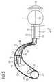
- FIG. 5is a schematic longitudinal section taken through a further variation of the behind-the-ear (BTE) hearing unit with an inflation pump and a receiver in the behind-the-ear housing.
- BTEbehind-the-ear
- FIG. 1there is seen a human ear 1 and an external auditory canal 2 .
- the auditory canalis bounded by a tympanic membrane 3 , also referred to as an eardrum.
- pressure wavessound waves are longitudinal pressure waves
- the external auditory canal 2also referred to as the ear canal or, simply canal, before they impinge on the tympanic membrane 3 .
- the propagation of the sound waves through the auditory canal 2may be interrupted.
- the sound wavesare instead picked up by a microphone or the like, the resulting signal is processed, typically by way of digital signal processing, and the processed signal is utilized to excite a loudspeaker, typically in the vicinity of or at the tympanic membrane 3 .
- the sound wavesare directly injected at the concha 1 a for delivery through the auditory canal 2 .
- an ear piece 4is formed in a unitary construction with a hearing device 10 . That is, there is shown here a hearing aid in the form of an in-the-ear (ITE) unit or a completely-in-the-canal (CIC) hearing unit.
- a receiver module 5connects to a carrier module 6 , also referred to as a carrier 6 , which, in turn, carries an inflatable member 7 .
- the inflatable member 7is a balloon or a bag or an accordion-type bellows. While we may simply refer to the inflatable member as a balloon 7 , the term “balloon” should be understood in its broadest sense as any inflatable member.
- the balloon 7may be in the form of a balloon with resiliently stretchable material, or a bag, or an accordion-type bellows with folded/crimped balloon shapes. Further the material is chosen such that it provides a pleasant haptic feel as it is pressed against the wall of the ear canal 2 and, once inflated, does not shift relative to the canal 2 .
- the balloon 7is formed of a flexible material which is impermeable to cerumen, or ear-wax, and also to water.
- the balloon 7is preferably formed of silicone or latex, or any of the known flexible materials that are used for otoplasties and other cavity-insertible products known, especially, in the hearing aid arts. It may further be covered on the laterally outside walls, i.e., the walls that are braced into contact with the walls of the ear canal 2 , with a soft silicone or rubber material layer.
- the balloon 7resembles a tubeless tire, that is, it is sealed against the rim of the carrier 6 and, upon inflation, it forms a doughnut-shaped thoroid fluid space.
- the receiver module 5carries one or two pumps 8 forming the compressed air sources for inflating the balloon 7 .
- the pumps 8are fully integrated in and form a part of the receiver module 5 . It is also possible, however, for the pumps 8 to be fixedly mounted to (or, integrated with) the carrier 6 . In this case, the carrier 6 and the pumps 8 may be removed together from the receiver module 5 in order to exchange the inflatable member (i.e., the carrier and the balloon).
- valve 9for enabling the balloon 7 to be deflated, for removal or simply to alleviate the occlusion afforded by the earpiece 4 .
- the valve 9may be provided in the pump(s) 8 or in the pneumatic line traversing the interface, i.e., the carrier 6 .
- the pressurization and the deflation of the balloonare schematically indicated by the two-way arrow at the air inlet into the balloon 7 .
- the receiver module 5contains the necessary electronics for generating a speaker signal for conversion to sound waves at the forward end of the inflatable ear mold and for delivery to the tympanic membrane 3 .
- the forward end of the receiver 5may be formed with a sound opening through which the sound waves 5 a are delivered in the direction toward the ear drum 3 .
- the sound signalis generated in the receiver module 5 .
- the necessary poweris sup-plied from a battery 11 inside the insertible housing 12 of the device 10 .
- the housing 12which is also formed with an access door 13 (e.g., for exchanging the battery 11 , or the filter 14 ), is formed of conventional otoplastic materials, as they are well known in the hearing aid art.
- the battery 11also provides the necessary power for the pump 8 and, if necessary, for the valve 9 .
- the pump 8pumps the air for inflating the balloon 7 through an air supply duct 15 , which extends from an air intake opening 16 to the air inlet into the balloon 7 .
- the valve 9is disposed inline in the duct 15 .
- the valve 9enables selective closing of the duct and thus pneumatic sealing of the interior of the balloon 7 .
- the air intake opening 16 and the inlet into the duct 15are preferably covered by an extra filter 14 , which may be a foam filter or a filter membrane.
- the filter 14may be removable and exchangeable by the user or by an audiologist.
- the air intakeis thus protected against the rather contaminated environment in the ear canal (i.e., against cerumen, flaking particles, greasy fumes, moisture, etc.) in that the air is aspirated through or at the cover lid 13 .
- the latteris exposed to the outside of the ear, or it is placed in the concha, with free access “clean” inflation air.
- the receiver module 5 in FIG. 2generates the necessary sound signal directly.
- the required microphone and the electrical connection to the battery and the microphoneare not illustrated, so as not to unnecessarily complicate the description.
- the receiver module 5receives its information signal from an external assembly through a signal line 17 . That is, the ear piece (IEM, insertable ear mold) may be tethered to an external assembly in the form of a behind-the-ear (BTE) unit or a concha unit.
- BTEbehind-the-ear
- FIG. 3there is shown an embodiment of the invention with an inflatable ear mold, i.e., a receiver in the canal, and a behind-the-ear (BTE) hearing unit.
- the receiver 5is connected by way of an electrical signal line 17 to an amplifier 18 , which generates the necessary signals for presentation to the ear drum 3 .
- the ambient soundis picked up through one or more microphones 19 strategically disposed on the housing 20 of the BTE unit.
- the amplifier and all other electronic devices in the housing, as well as in the receiverare supplied with energy from a battery (BAT) 21 .
- BATbattery
- the various electrical connections inside the housing 20are not illustrated so as not to unnecessarily complicate the description.
- the housing 20is connected to the receiver module 5 by way of tubing 22 .
- Air for inflating the balloon 7 by way of the pump 8is aspirated through the tubing 22 , which is sealed in an air-tight manner to the air intake 16 , on the one hand, and to the housing 20 , on the other hand.
- the tubing 22is sealed at an air duct 23 formed in the housing 20 , so that the air is aspirated from the BTE housing 20 .
- the housing 20is formed with air intake openings 24 , or an air grill or the like. If desired, an air filter may be strategically disposed at the intake openings 24 or at the air duct 20 .
- a filtermay also be inserted in the tubing or at the interface between the tubing 22 and the housing 20 . Such a filter is then easily exchanged, either by the user or by an audiologist.
- a further alternative embodiment of a behind-the-ear (BTE) hearing aidhas the pump 8 and the valve 9 disposed in the housing 20 instead of in the ear mold.
- the tubingis sealed air-tight or fluid-tight between the receiver 5 and the housing 20 and, more particularly, the pump 8 and valve 9 .
- the pump 8aspirates air from inside the housing 20 and the housing 20 is formed with air intake openings 24 .
- a filter 14may be provided, either at the intake opening of the pump 8 or at the intake and air ingress openings 24 .
- the soundis generated inside the housing, and travels to and through the balloon module via a sound tube 25 . That is, the sound waves 5 b are delivered through the sound tube 5 b from the receiver 5 , inside the tubing 22 which acts as a sheath, and through the ear mold 4 , where the sound waves 5 a issue towards the ear drum 3 .
- the inflation air from the pump 8may be delivered via a pressure hose 26 , as illustrated in FIG. 5 . It may also be delivered, as in FIG. 4 , through the tubing 22 . In the former case, it is not necessary to connect the housing 20 to the ear mold in a fluid-tight manner.
Landscapes
- Engineering & Computer Science (AREA)
- Physics & Mathematics (AREA)
- Acoustics & Sound (AREA)
- Signal Processing (AREA)
- Manufacturing & Machinery (AREA)
- Health & Medical Sciences (AREA)
- General Health & Medical Sciences (AREA)
- Neurosurgery (AREA)
- Otolaryngology (AREA)
- Headphones And Earphones (AREA)
- Percussion Or Vibration Massage (AREA)
Abstract
Description
- an inflatable balloon sealingly mounted on a carrier, the carrier and the balloon forming a unit configured for insertion into an auditory canal of a hearing device user;
- a receiver module for generating an audible sound signal to be delivered in the auditory canal;
- a pressure source fluidically connected through the carrier to an interior space of the inflatable balloon for selectively inflating the balloon; and
- an intake opening connected to the pressure source and enabling aspiration of a pressure medium by the pressure source, wherein the intake opening is disposed inside a housing and the housing is formed with an inlet for aspiration of the pressure medium from outside the auditory canal of the hearing device user.
Claims (10)
Priority Applications (1)
| Application Number | Priority Date | Filing Date | Title |
|---|---|---|---|
| US13/809,793US8903113B2 (en) | 2010-07-13 | 2011-04-08 | Inflatable ear mold with protected inflation air inlet |
Applications Claiming Priority (4)
| Application Number | Priority Date | Filing Date | Title |
|---|---|---|---|
| US36381410P | 2010-07-13 | 2010-07-13 | |
| US38563510P | 2010-09-23 | 2010-09-23 | |
| US13/809,793US8903113B2 (en) | 2010-07-13 | 2011-04-08 | Inflatable ear mold with protected inflation air inlet |
| PCT/EP2011/055520WO2012007193A1 (en) | 2010-07-13 | 2011-04-08 | Inflatable ear mold with protected inflation air inlet |
Related Parent Applications (1)
| Application Number | Title | Priority Date | Filing Date |
|---|---|---|---|
| PCT/EP2011/055520A-371-Of-InternationalWO2012007193A1 (en) | 2010-07-13 | 2011-04-08 | Inflatable ear mold with protected inflation air inlet |
Related Child Applications (1)
| Application Number | Title | Priority Date | Filing Date |
|---|---|---|---|
| US14/444,223ContinuationUS9226086B2 (en) | 2010-07-13 | 2014-07-28 | Inflatable ear mold with protected inflation air inlet |
Publications (2)
| Publication Number | Publication Date |
|---|---|
| US20130114839A1 US20130114839A1 (en) | 2013-05-09 |
| US8903113B2true US8903113B2 (en) | 2014-12-02 |
Family
ID=44169197
Family Applications (3)
| Application Number | Title | Priority Date | Filing Date |
|---|---|---|---|
| US13/809,793Expired - Fee RelatedUS8903113B2 (en) | 2010-07-13 | 2011-04-08 | Inflatable ear mold with protected inflation air inlet |
| US13/702,665Expired - Fee RelatedUS8548181B2 (en) | 2010-07-13 | 2011-07-13 | Inflatable ear mold connection system |
| US14/444,223Expired - Fee RelatedUS9226086B2 (en) | 2010-07-13 | 2014-07-28 | Inflatable ear mold with protected inflation air inlet |
Family Applications After (2)
| Application Number | Title | Priority Date | Filing Date |
|---|---|---|---|
| US13/702,665Expired - Fee RelatedUS8548181B2 (en) | 2010-07-13 | 2011-07-13 | Inflatable ear mold connection system |
| US14/444,223Expired - Fee RelatedUS9226086B2 (en) | 2010-07-13 | 2014-07-28 | Inflatable ear mold with protected inflation air inlet |
Country Status (5)
| Country | Link |
|---|---|
| US (3) | US8903113B2 (en) |
| EP (2) | EP2594086A1 (en) |
| CN (1) | CN102972044B (en) |
| DK (1) | DK2594091T3 (en) |
| WO (2) | WO2012007193A1 (en) |
Cited By (6)
| Publication number | Priority date | Publication date | Assignee | Title |
|---|---|---|---|---|
| US10897678B2 (en) | 2008-10-15 | 2021-01-19 | Staton Techiya, Llc | Device and method to reduce ear wax clogging of acoustic ports, hearing aid sealing system, and feedback reduction system |
| US12183341B2 (en) | 2008-09-22 | 2024-12-31 | St Casestech, Llc | Personalized sound management and method |
| US12193841B2 (en) | 2014-12-10 | 2025-01-14 | The Diablo Canyon Collective Llc | Sensor control of an audio device |
| US12249326B2 (en) | 2007-04-13 | 2025-03-11 | St Case1Tech, Llc | Method and device for voice operated control |
| US12256188B2 (en) | 2018-03-09 | 2025-03-18 | Earsoft, Llc | Eartips and earphone devices, and systems and methods therefore |
| US12289576B2 (en) | 2007-07-12 | 2025-04-29 | St Tiptech, Llc | Expandable sealing devices and methods |
Families Citing this family (45)
| Publication number | Priority date | Publication date | Assignee | Title |
|---|---|---|---|---|
| US10009677B2 (en) | 2007-07-09 | 2018-06-26 | Staton Techiya, Llc | Methods and mechanisms for inflation |
| EP2594085B1 (en)* | 2010-07-13 | 2018-10-10 | Sivantos Pte. Ltd. | Inflatable ear piece with pressure relief valve |
| EP2598215A4 (en)* | 2010-07-28 | 2014-01-29 | Sunbeam Products Inc | Pelvic muscle trainer |
| US10362381B2 (en)* | 2011-06-01 | 2019-07-23 | Staton Techiya, Llc | Methods and devices for radio frequency (RF) mitigation proximate the ear |
| US9288592B2 (en)* | 2012-02-02 | 2016-03-15 | Conversion Sound Inc. | Custom ear adaptor system with balloon-style or elastomeric dome earpiece |
| US9380379B1 (en)* | 2012-03-14 | 2016-06-28 | Google Inc. | Bone-conduction anvil and diaphragm |
| US20130251172A1 (en)* | 2012-03-21 | 2013-09-26 | Jack Mosseri | Inflatable Ear Buds |
| KR20140002816A (en)* | 2012-06-25 | 2014-01-09 | 한국전자통신연구원 | Apparatus and method for transmitting acoustic signal using human body |
| DE102012217844A1 (en)* | 2012-07-06 | 2014-01-09 | Siemens Medical Instruments Pte. Ltd. | Pumping device for hearing aid |
| DE102012214976B3 (en)* | 2012-08-23 | 2013-11-07 | Siemens Medical Instruments Pte. Ltd. | Hearing instrument and earpiece with receiver |
| DE102012221233A1 (en)* | 2012-09-12 | 2014-03-13 | Siemens Medical Instruments Pte. Ltd. | Coupling hearing device for a hearing device |
| US20140119586A1 (en)* | 2012-10-25 | 2014-05-01 | Sonion A/S | Hearing aid assembly |
| US20140205123A1 (en)* | 2013-01-23 | 2014-07-24 | Sonion Nederland B.V. | Balloon connector for a hearing aid assembly |
| DE102013203334B3 (en) | 2013-02-28 | 2014-05-22 | Siemens Medical Instruments Pte. Ltd. | Valve device, hearing aid and method |
| EP2819435A1 (en)* | 2013-06-26 | 2014-12-31 | Oticon A/s | Vented dome |
| US10251790B2 (en) | 2013-06-28 | 2019-04-09 | Nocira, Llc | Method for external ear canal pressure regulation to alleviate disorder symptoms |
| US12396892B2 (en) | 2013-06-28 | 2025-08-26 | Nocira, Llc | External ear canal pressure regulation device |
| US9039639B2 (en) | 2013-06-28 | 2015-05-26 | Gbs Ventures Llc | External ear canal pressure regulation system |
| DK3550852T3 (en)* | 2014-02-14 | 2021-02-01 | Sonion Nederland Bv | A joiner for a receiver assembly |
| US10194230B2 (en)* | 2014-08-15 | 2019-01-29 | Voyetra Turtle Beach, Inc. | Earphones with motion sensitive inflation |
| CN104473719A (en)* | 2014-12-08 | 2015-04-01 | 上海斐讯数据通信技术有限公司 | Earplug |
| US10418016B2 (en) | 2015-05-29 | 2019-09-17 | Staton Techiya, Llc | Methods and devices for attenuating sound in a conduit or chamber |
| DK3116238T3 (en)* | 2015-07-08 | 2020-03-23 | Oticon As | SPACES AND HEARING DEVICE INCLUDING IT |
| US10045107B2 (en)* | 2015-07-21 | 2018-08-07 | Harman International Industries, Incorporated | Eartip that conforms to a user's ear canal |
| US10129634B2 (en) | 2016-04-19 | 2018-11-13 | Christopher Robert Barry | Human-ear-wearable apparatus, system, and method of operation |
| US11457323B2 (en) | 2016-04-26 | 2022-09-27 | Gn Hearing A/S | Custom elastomeric earmold with secondary material infusion |
| CN105979427A (en)* | 2016-07-19 | 2016-09-28 | 华峰君 | Energy-saving smart earphone |
| US10760566B2 (en) | 2016-07-22 | 2020-09-01 | Nocira, Llc | Magnetically driven pressure generator |
| EP3334179B1 (en)* | 2016-12-12 | 2021-10-13 | Oticon A/s | Hearing aid with an extended dome |
| EP4424293A3 (en) | 2017-02-27 | 2024-11-27 | Nocira, LLC | Ear pumps |
| RU2680663C2 (en)* | 2017-08-08 | 2019-02-25 | Михаил Викторович Кучеренко | In-ear headphone |
| CN108324426B (en)* | 2018-03-26 | 2019-10-18 | 桂林市兴达光电医疗器械有限公司 | A kind of ear protection device |
| JP7277872B2 (en)* | 2018-04-25 | 2023-05-19 | 積水ポリマテック株式会社 | earpiece |
| EP3810049A4 (en) | 2018-06-22 | 2022-03-23 | Nocira, LLC | Systems and methods for treating neurological disorders |
| US20200078509A1 (en)* | 2018-09-12 | 2020-03-12 | Xinova, LLC | Micro-dispenser based ear treatment |
| US11418865B2 (en)* | 2018-12-07 | 2022-08-16 | Gn Hearing A/S | Configurable hearing devices |
| WO2020121608A1 (en) | 2018-12-14 | 2020-06-18 | ソニー株式会社 | Acoustic device and acoustic system |
| US10506320B1 (en) | 2019-01-10 | 2019-12-10 | Phillip Dale Lott | Dynamic earphone tip |
| CN111065028A (en)* | 2019-12-27 | 2020-04-24 | 歌尔股份有限公司 | Vibrating diaphragm ball top, vibrating diaphragm and loudspeaker |
| CN111491246B (en)* | 2020-04-24 | 2021-07-27 | 朱海涛 | Multifunctional hearing aid |
| CN114554336A (en)* | 2020-11-25 | 2022-05-27 | 深圳富泰宏精密工业有限公司 | Earphone set |
| CN112788462B (en)* | 2021-01-14 | 2022-08-26 | 深圳市弘毅佳科技有限公司 | In-ear earphone capable of avoiding ear ache |
| CN113271528B (en)* | 2021-07-19 | 2021-11-19 | 西安交通大学医学院第二附属医院 | Medical audiphone suitable for otolaryngology branch of academic or vocational study |
| CN113794977B (en)* | 2021-09-28 | 2024-04-05 | 武汉左点科技有限公司 | Quick self-adaptive adjusting method and device for hearing aid system |
| US12418759B2 (en) | 2023-03-20 | 2025-09-16 | Sonova Ag | Hearing device having a shell that includes a compressible region and methods of manufacturing the same |
Citations (8)
| Publication number | Priority date | Publication date | Assignee | Title |
|---|---|---|---|---|
| DE2737252A1 (en) | 1976-09-01 | 1978-03-02 | Koken Co | HOERGERAET |
| US4834211A (en) | 1988-02-02 | 1989-05-30 | Kenneth Bibby | Anchoring element for in-the-ear devices |
| US7227968B2 (en) | 2001-06-25 | 2007-06-05 | Sonion Roskilde A/S | Expandsible Receiver Module |
| US7425196B2 (en) | 2002-12-23 | 2008-09-16 | Sonion Roskilde A/S | Balloon encapsulated direct drive |
| US20090023976A1 (en) | 2007-07-20 | 2009-01-22 | Kyungpook National University Industry-Academic Corporation Foundation | Implantable middle ear hearing device having tubular vibration transducer to drive round window |
| US20100002897A1 (en) | 2008-07-06 | 2010-01-07 | Personics Holdings Inc. | Pressure regulating systems for expandable insertion devices |
| WO2010094034A1 (en) | 2009-02-13 | 2010-08-19 | Personics Holdings Inc. | Method and device for acoustic sealing and occulsion effect mitigation |
| US8391534B2 (en)* | 2008-07-23 | 2013-03-05 | Asius Technologies, Llc | Inflatable ear device |
Family Cites Families (4)
| Publication number | Priority date | Publication date | Assignee | Title |
|---|---|---|---|---|
| CN101098566A (en)* | 2006-06-30 | 2008-01-02 | 陈浩 | Gas-controlled compact earphone |
| US8340310B2 (en)* | 2007-07-23 | 2012-12-25 | Asius Technologies, Llc | Diaphonic acoustic transduction coupler and ear bud |
| AU2010247865A1 (en) | 2009-05-09 | 2012-01-12 | Asius Technologies, Llc | Inflatable ear device |
| WO2011041900A1 (en) | 2009-10-05 | 2011-04-14 | Sonomax Technologies Inc. | Pressure regulation mechanism for inflatable in-ear device |
- 2011
- 2011-04-08USUS13/809,793patent/US8903113B2/ennot_activeExpired - Fee Related
- 2011-04-08WOPCT/EP2011/055520patent/WO2012007193A1/enactiveApplication Filing
- 2011-04-08CNCN201180033433.1Apatent/CN102972044B/ennot_activeExpired - Fee Related
- 2011-04-08EPEP11714736.3Apatent/EP2594086A1/ennot_activeWithdrawn
- 2011-07-13WOPCT/EP2011/061962patent/WO2012007508A2/enactiveApplication Filing
- 2011-07-13DKDK11732446.7Tpatent/DK2594091T3/enactive
- 2011-07-13USUS13/702,665patent/US8548181B2/ennot_activeExpired - Fee Related
- 2011-07-13EPEP11732446.7Apatent/EP2594091B1/ennot_activeNot-in-force
- 2014
- 2014-07-28USUS14/444,223patent/US9226086B2/ennot_activeExpired - Fee Related
Patent Citations (11)
| Publication number | Priority date | Publication date | Assignee | Title |
|---|---|---|---|---|
| DE2737252A1 (en) | 1976-09-01 | 1978-03-02 | Koken Co | HOERGERAET |
| US4133984A (en) | 1976-09-01 | 1979-01-09 | Koken Co., Ltd. | Plug-type hearing device |
| US4834211A (en) | 1988-02-02 | 1989-05-30 | Kenneth Bibby | Anchoring element for in-the-ear devices |
| US7227968B2 (en) | 2001-06-25 | 2007-06-05 | Sonion Roskilde A/S | Expandsible Receiver Module |
| US7425196B2 (en) | 2002-12-23 | 2008-09-16 | Sonion Roskilde A/S | Balloon encapsulated direct drive |
| US20090023976A1 (en) | 2007-07-20 | 2009-01-22 | Kyungpook National University Industry-Academic Corporation Foundation | Implantable middle ear hearing device having tubular vibration transducer to drive round window |
| US20100002897A1 (en) | 2008-07-06 | 2010-01-07 | Personics Holdings Inc. | Pressure regulating systems for expandable insertion devices |
| US8391534B2 (en)* | 2008-07-23 | 2013-03-05 | Asius Technologies, Llc | Inflatable ear device |
| US8526652B2 (en)* | 2008-07-23 | 2013-09-03 | Sonion Nederland Bv | Receiver assembly for an inflatable ear device |
| WO2010094034A1 (en) | 2009-02-13 | 2010-08-19 | Personics Holdings Inc. | Method and device for acoustic sealing and occulsion effect mitigation |
| US20120101514A1 (en) | 2009-02-13 | 2012-04-26 | Personics Holdings Inc | Method and device for acoustic sealing and occlusion effect mitigation |
Cited By (13)
| Publication number | Priority date | Publication date | Assignee | Title |
|---|---|---|---|---|
| US12249326B2 (en) | 2007-04-13 | 2025-03-11 | St Case1Tech, Llc | Method and device for voice operated control |
| US12289576B2 (en) | 2007-07-12 | 2025-04-29 | St Tiptech, Llc | Expandable sealing devices and methods |
| US12183341B2 (en) | 2008-09-22 | 2024-12-31 | St Casestech, Llc | Personalized sound management and method |
| US12374332B2 (en) | 2008-09-22 | 2025-07-29 | ST Fam Tech, LLC | Personalized sound management and method |
| US11638109B2 (en) | 2008-10-15 | 2023-04-25 | Staton Techiya, Llc | Device and method to reduce ear wax clogging of acoustic ports, hearing aid sealing system, and feedback reduction system |
| US11700495B2 (en) | 2008-10-15 | 2023-07-11 | Staton Techiya Llc | Device and method to reduce ear wax clogging of acoustic ports, hearing aid sealing system, and feedback reduction system |
| US11956600B2 (en) | 2008-10-15 | 2024-04-09 | The Diablo Canyon Collective Llc | Device and method to reduce ear wax clogging of acoustic ports, hearing aid sealing system, and feedback reduction system |
| US10897678B2 (en) | 2008-10-15 | 2021-01-19 | Staton Techiya, Llc | Device and method to reduce ear wax clogging of acoustic ports, hearing aid sealing system, and feedback reduction system |
| US12212936B2 (en) | 2008-10-15 | 2025-01-28 | The Diablo Canyon Collective Llc | Device and method to reduce ear wax clogging of acoustic ports, hearing aid sealing system, and feedback reduction system |
| US11223918B2 (en) | 2008-10-15 | 2022-01-11 | Staton Techiya, Llc | Device and method to reduce ear wax clogging of acoustic ports, hearing aid sealing system, and feedback reduction system |
| US10979831B2 (en) | 2008-10-15 | 2021-04-13 | Staton Techiya, Llc | Device and method to reduce ear wax clogging of acoustic ports, hearing aid sealing system, and feedback reduction system |
| US12193841B2 (en) | 2014-12-10 | 2025-01-14 | The Diablo Canyon Collective Llc | Sensor control of an audio device |
| US12256188B2 (en) | 2018-03-09 | 2025-03-18 | Earsoft, Llc | Eartips and earphone devices, and systems and methods therefore |
Also Published As
| Publication number | Publication date |
|---|---|
| US8548181B2 (en) | 2013-10-01 |
| EP2594091A2 (en) | 2013-05-22 |
| US20140334652A1 (en) | 2014-11-13 |
| WO2012007508A2 (en) | 2012-01-19 |
| EP2594091B1 (en) | 2014-06-04 |
| DK2594091T3 (en) | 2014-09-15 |
| WO2012007193A1 (en) | 2012-01-19 |
| US9226086B2 (en) | 2015-12-29 |
| WO2012007508A3 (en) | 2013-03-28 |
| CN102972044B (en) | 2016-03-16 |
| US20130101147A1 (en) | 2013-04-25 |
| EP2594086A1 (en) | 2013-05-22 |
| CN102972044A (en) | 2013-03-13 |
| US20130114839A1 (en) | 2013-05-09 |
Similar Documents
| Publication | Publication Date | Title |
|---|---|---|
| US9226086B2 (en) | Inflatable ear mold with protected inflation air inlet | |
| EP2594085B1 (en) | Inflatable ear piece with pressure relief valve | |
| EP1272003B1 (en) | An expansible receiver module | |
| US20190208301A1 (en) | Audio device with acoustic valve | |
| CN101272638B (en) | Hearing aid | |
| US8792663B2 (en) | Hearing device with an open earpiece having a short vent | |
| CN103634729B (en) | Sound equipment utensil and the ear piece of band receiver | |
| CN103517195B (en) | Hybrid sound equipment utensil system connector | |
| CN103416077A (en) | Hearing device with a transducer module and method for manufacturing a transducer module | |
| US9668067B2 (en) | Hearing device with improved low frequency response and method for manufacturing such a hearing device | |
| CN218587332U (en) | Hearing device | |
| US11178497B2 (en) | In-ear receiver | |
| WO2012113462A1 (en) | Inflatable ear mold connection system | |
| CN116896701A (en) | Hearing device | |
| CN115412794A (en) | A hearing instrument comprising a sound path component | |
| CN102905216B (en) | Hearing apparatus having a special sound channel | |
| CN114640915A (en) | In-ear acoustic device | |
| CN218587333U (en) | Hearing device | |
| WO2012007187A2 (en) | Inflatable ear mold interface connection system | |
| EP4615006A1 (en) | Vibration insulation suspension for ear wearable audio components | |
| CN116896702A (en) | hearing device | |
| CN116896700A (en) | hearing equipment | |
| EP3086573B1 (en) | A hearing device configured to be placed in the ear canal of a user |
Legal Events
| Date | Code | Title | Description |
|---|---|---|---|
| AS | Assignment | Owner name:SIEMENS AUDIOLOGISCHE TECHNIK GMBH, GERMANY Free format text:ASSIGNMENT OF ASSIGNORS INTEREST;ASSIGNOR:GEBERT, ANTON;REEL/FRAME:029629/0292 Effective date:20121211 | |
| AS | Assignment | Owner name:SIEMENS MEDICAL INSTRUMENTS PTE. LTD., SINGAPORE Free format text:ASSIGNMENT OF ASSIGNORS INTEREST;ASSIGNOR:SIEMENS AUDIOLOGISCHE TECHNIK GMBH;REEL/FRAME:029694/0379 Effective date:20121218 | |
| FEPP | Fee payment procedure | Free format text:PAYER NUMBER DE-ASSIGNED (ORIGINAL EVENT CODE: RMPN); ENTITY STATUS OF PATENT OWNER: LARGE ENTITY Free format text:PAYOR NUMBER ASSIGNED (ORIGINAL EVENT CODE: ASPN); ENTITY STATUS OF PATENT OWNER: LARGE ENTITY | |
| STCF | Information on status: patent grant | Free format text:PATENTED CASE | |
| AS | Assignment | Owner name:SIVANTOS PTE. LTD., SINGAPORE Free format text:CHANGE OF NAME;ASSIGNOR:SIEMENS MEDICAL INSTRUMENTS PTE. LTD.;REEL/FRAME:036089/0827 Effective date:20150416 | |
| MAFP | Maintenance fee payment | Free format text:PAYMENT OF MAINTENANCE FEE, 4TH YEAR, LARGE ENTITY (ORIGINAL EVENT CODE: M1551) Year of fee payment:4 | |
| FEPP | Fee payment procedure | Free format text:MAINTENANCE FEE REMINDER MAILED (ORIGINAL EVENT CODE: REM.); ENTITY STATUS OF PATENT OWNER: LARGE ENTITY | |
| LAPS | Lapse for failure to pay maintenance fees | Free format text:PATENT EXPIRED FOR FAILURE TO PAY MAINTENANCE FEES (ORIGINAL EVENT CODE: EXP.); ENTITY STATUS OF PATENT OWNER: LARGE ENTITY | |
| STCH | Information on status: patent discontinuation | Free format text:PATENT EXPIRED DUE TO NONPAYMENT OF MAINTENANCE FEES UNDER 37 CFR 1.362 | |
| FP | Lapsed due to failure to pay maintenance fee | Effective date:20221202 |