US8902195B2 - Interactive input system with improved signal-to-noise ratio (SNR) and image capture method - Google Patents
Interactive input system with improved signal-to-noise ratio (SNR) and image capture methodDownload PDFInfo
- Publication number
- US8902195B2 US8902195B2US12/873,998US87399810AUS8902195B2US 8902195 B2US8902195 B2US 8902195B2US 87399810 AUS87399810 AUS 87399810AUS 8902195 B2US8902195 B2US 8902195B2
- Authority
- US
- United States
- Prior art keywords
- radiation source
- radiation
- imaging device
- optical waveguide
- image frames
- Prior art date
- Legal status (The legal status is an assumption and is not a legal conclusion. Google has not performed a legal analysis and makes no representation as to the accuracy of the status listed.)
- Active, expires
Links
Images


Classifications
- G—PHYSICS
- G06—COMPUTING OR CALCULATING; COUNTING
- G06F—ELECTRIC DIGITAL DATA PROCESSING
- G06F3/00—Input arrangements for transferring data to be processed into a form capable of being handled by the computer; Output arrangements for transferring data from processing unit to output unit, e.g. interface arrangements
- G06F3/01—Input arrangements or combined input and output arrangements for interaction between user and computer
- G06F3/03—Arrangements for converting the position or the displacement of a member into a coded form
- G06F3/041—Digitisers, e.g. for touch screens or touch pads, characterised by the transducing means
- G06F3/042—Digitisers, e.g. for touch screens or touch pads, characterised by the transducing means by opto-electronic means
- G06F3/0428—Digitisers, e.g. for touch screens or touch pads, characterised by the transducing means by opto-electronic means by sensing at the edges of the touch surface the interruption of optical paths, e.g. an illumination plane, parallel to the touch surface which may be virtual
- G—PHYSICS
- G06—COMPUTING OR CALCULATING; COUNTING
- G06F—ELECTRIC DIGITAL DATA PROCESSING
- G06F3/00—Input arrangements for transferring data to be processed into a form capable of being handled by the computer; Output arrangements for transferring data from processing unit to output unit, e.g. interface arrangements
- G06F3/01—Input arrangements or combined input and output arrangements for interaction between user and computer
- G06F3/03—Arrangements for converting the position or the displacement of a member into a coded form
- G06F3/033—Pointing devices displaced or positioned by the user, e.g. mice, trackballs, pens or joysticks; Accessories therefor
- G06F3/038—Control and interface arrangements therefor, e.g. drivers or device-embedded control circuitry
- G06F3/0386—Control and interface arrangements therefor, e.g. drivers or device-embedded control circuitry for light pen
- G—PHYSICS
- G06—COMPUTING OR CALCULATING; COUNTING
- G06F—ELECTRIC DIGITAL DATA PROCESSING
- G06F3/00—Input arrangements for transferring data to be processed into a form capable of being handled by the computer; Output arrangements for transferring data from processing unit to output unit, e.g. interface arrangements
- G06F3/01—Input arrangements or combined input and output arrangements for interaction between user and computer
- G06F3/03—Arrangements for converting the position or the displacement of a member into a coded form
- G06F3/041—Digitisers, e.g. for touch screens or touch pads, characterised by the transducing means
- G06F3/0416—Control or interface arrangements specially adapted for digitisers
- G—PHYSICS
- G06—COMPUTING OR CALCULATING; COUNTING
- G06F—ELECTRIC DIGITAL DATA PROCESSING
- G06F3/00—Input arrangements for transferring data to be processed into a form capable of being handled by the computer; Output arrangements for transferring data from processing unit to output unit, e.g. interface arrangements
- G06F3/01—Input arrangements or combined input and output arrangements for interaction between user and computer
- G06F3/03—Arrangements for converting the position or the displacement of a member into a coded form
- G06F3/041—Digitisers, e.g. for touch screens or touch pads, characterised by the transducing means
- G06F3/042—Digitisers, e.g. for touch screens or touch pads, characterised by the transducing means by opto-electronic means
- G06F3/0425—Digitisers, e.g. for touch screens or touch pads, characterised by the transducing means by opto-electronic means using a single imaging device like a video camera for tracking the absolute position of a single or a plurality of objects with respect to an imaged reference surface, e.g. video camera imaging a display or a projection screen, a table or a wall surface, on which a computer generated image is displayed or projected
- G—PHYSICS
- G06—COMPUTING OR CALCULATING; COUNTING
- G06F—ELECTRIC DIGITAL DATA PROCESSING
- G06F2203/00—Indexing scheme relating to G06F3/00 - G06F3/048
- G06F2203/041—Indexing scheme relating to G06F3/041 - G06F3/045
- G06F2203/04109—FTIR in optical digitiser, i.e. touch detection by frustrating the total internal reflection within an optical waveguide due to changes of optical properties or deformation at the touch location
Definitions
- the present inventionrelates generally to interactive input systems and in particular, to an interactive input system with improved signal-to-noise ratio and to an image capture method.
- Interactive input systemsthat allow users to inject input (eg. digital ink, mouse events etc.) into an application program using an active pointer (eg. a pointer that emits light, sound or other signal), a passive pointer (eg. a finger, cylinder or other suitable object) or other suitable input device such as for example, a mouse or trackball, are known.
- active pointereg. a pointer that emits light, sound or other signal
- a passive pointereg. a finger, cylinder or other suitable object
- suitable input devicesuch as for example, a mouse or trackball
- U.S. Pat. No. 6,803,906 to Morrison et al.discloses a touch system that employs machine vision to detect pointer interaction with a touch surface on which a computer-generated image is presented.
- a rectangular bezel or framesurrounds the touch surface and supports imaging devices in the form of digital cameras at its corners.
- the digital camerashave overlapping fields of view that encompass and look generally across the touch surface.
- the digital camerasacquire images looking across the touch surface from different vantages and generate image data.
- Image data acquired by the digital camerasis processed by on-board digital signal processors to determine if a pointer exists in the captured image data.
- the digital signal processorsconvey pointer characteristic data to a master controller, which in turn processes the pointer characteristic data to determine the location of the pointer in (x,y) coordinates relative to the touch surface using triangulation.
- the pointer coordinatesare conveyed to a computer executing one or more application programs.
- the computeruses the pointer coordinates to update the computer-generated image that is presented on the touch surface. Pointer contacts on the touch surface can therefore be recorded as writing or drawing or used to control execution of application programs executed by the computer.
- Multi-touch interactive input systemsthat receive and process input from multiple pointers using machine vision are also known.
- One such type of multi-touch interactive input systemexploits the well-known optical phenomenon of frustrated total internal reflection (FTIR).
- FTIRfrustrated total internal reflection
- the machine vision systemcaptures images including the point(s) of escaped light, and processes the images to identify the position of the pointers on the optical waveguide surface based on the point(s) of escaped light for use as input to application programs.
- a compliant surface overlayis disposed adjacent the contact surface of the acrylic sheet, with another small gap between the two layers in order to prevent the compliant surface overlay from frustrating the total internal reflection unless it has been touched.
- the compliant surface overlayin turn touches the acrylic sheet and frustrates the total internal reflection.
- illumination sourcesare often used with interactive input systems that employ imaging devices. These illumination sources emit radiation that is either occluded by pointers so that pointers appear as dark regions in an otherwise light image frame, or reflected by the pointers so that pointers appear as light regions in an otherwise dark image frame.
- U.S. Pat. No. 6,972,401 to Akitt et al. issued on Dec. 6, 2005 and assigned to SMART Technologies ULCdiscloses an illuminated bezel for use in a touch system such as that described in above-incorporated U.S. Pat. No. 6,803,906.
- the illuminated bezelemits infrared or other suitable radiation over the touch surface that is visible to the digital cameras.
- the illuminated bezelappears in captured images as a continuous bright or “white” band.
- the passive pointerWhen a passive pointer is brought into the fields of view of the digital cameras, the passive pointer occludes emitted radiation and appears as a dark region interrupting the bright or “white” band in captured images allowing the existence of the pointer in the captured images to be readily determined and its position determined using triangulation.
- illumination sourcesIn interactive input systems that employ illumination sources, ideally only illumination emitted by the illumination sources is detected by the imaging devices during image frame capture so that any pointer in the captured image frame can be clearly identified.
- detrimental lightsuch as for example sunlight, light emitted by external sources, glare etc. is also detected by the imaging devices. This detrimental light can have a negative impact on the quality of captured image frames making it more difficult to identify pointers in captured image frames. Improvements are therefore desired.
- an input panel for an interactive input systemcomprising: an optical waveguide; a first radiation source directing radiation into said optical waveguide, said radiation undergoing total internal reflection within said optical waveguide; a diffusion layer adjacent to and on one side of the optical waveguide, totally internally reflected light being frustrated and escaping the optical waveguide in response to the pointer contacts on the diffusion layer; a second radiation source directing radiation towards another side of the optical waveguide that is opposite the one side; and at least one imaging device having a field of view looking at the optical waveguide and capturing image frames, wherein said first and second radiation sources are turned on and off in succession and wherein said first radiation source is turned off when said second radiation source is on and wherein said first radiation source is turned on when said second radiation source is off.
- the exposure time of the at least one imaging deviceis selected to be less than the total image frame capture time, and wherein either the first or second illumination source is caused to emit radiation at a higher intensity during the shortened exposure time.
- an interactive input systemcomprising: at least one imaging device capturing image frames of a region of interest, wherein the exposure time of said at least one imaging device is less than a total image frame capture time; at least one radiation source emitting radiation into the region of interest during the exposure time; and processing structure processing images captured by said at least one imaging device to determine the presence of any pointers within the region of interest.
- a method of inputting information into an interactive input systemcomprising at least one imaging device capturing image frames of a region of interest, the method comprising: causing the at least one imaging device to its exposure time to be less than the total image frame capture time; emitting radiation from by at least one radiation source into the region of interest during the exposure time; and processing images captured by the at least one imaging device to determine presence of any pointers within the region of interest.
- an imaging assembly for an interactive input systemcomprising: at least one imaging device capturing image frames of a region of interest, wherein the exposure time of said at least one imaging device is less than a total image frame capture time; and at least one radiation source emitting radiation into the region of interest substantially only during the exposure time.
- FIG. 1is a perspective view of an interactive input system
- FIG. 2is a front elevational view of the interactive input system of FIG. 1 ;
- FIG. 3is a block diagram of an imaging assembly forming part of the interactive input system of FIG. 1 ;
- FIG. 4is a block diagram of a digital signal processor forming part of the interactive input system of FIG. 1 ;
- FIG. 5shows image sensor and IR light source timing diagrams
- FIG. 6 ais an image frame captured by the imaging assembly of FIG. 3 in the absence of a pointer within its field of view;
- FIG. 6 bis an image frame captured by the imaging assembly of FIG. 3 with a pointer within its field of view;
- FIG. 7is a perspective view of another embodiment of an interactive input system
- FIG. 8is a side sectional view of the interactive input system of FIG. 7 ;
- FIG. 9is a sectional view of a table top and touch panel forming part of the interactive input system of FIG. 7 ;
- FIG. 10is a sectional view of a portion of the touch panel of FIG. 9 , having been contacted by a pointer;
- FIGS. 11 a and 11 bare images captured by an imaging device forming part of the interactive input system of FIG. 7 ;
- FIG. 12shows imaging device and IR light source timing diagrams of the interactive input system of FIG. 7 ;
- FIG. 13shows imaging device and IR light source timing diagrams for an alternative operation of the interactive input system of FIG. 7 ;
- FIG. 14shows imaging device and IR light source timing diagrams for yet another alternative operation of the interactive input system of FIG. 7 ;
- FIG. 15is a side sectional view of yet another embodiment of an interactive input system
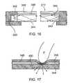
- FIG. 16is a sectional view of a table top and touch panel forming part of the interactive input system of FIG. 15 ;
- FIG. 17is a sectional view of a portion of the touch panel of FIG. 16 , having been contacted by a pointer;
- FIG. 18shows imaging device and IR light source timing diagrams for the interactive input system of FIG. 15 ;
- FIG. 19is a side elevational view of still yet another embodiment of an interactive input system.
- interactive input system 20that allows a user to inject input such as digital ink, mouse events etc. into an application program is shown and is generally identified by reference numeral 20 .
- interactive input system 20comprises an assembly 22 that engages a display unit (not shown) such as for example, a plasma television, a liquid crystal display (LCD) device, a flat panel display device, a cathode ray tube etc. and surrounds the display surface 24 of the display unit.
- the assembly 22employs machine vision to detect pointers brought into a region of interest in proximity with the display surface 24 and communicates with a digital signal processor (DSP) unit 26 via communication lines 28 .
- DSPdigital signal processor
- the communication lines 28may be embodied in a serial bus, a parallel bus, a universal serial bus (USB), an Ethernet connection or other suitable wired connection.
- the assembly 22may communicate with the DSP unit 26 over a wireless connection using a suitable wireless protocol such as for example Bluetooth, WiFi, ZigBee, ANT, IEEE 802.15.4, Z-Wave etc.
- the DSP unit 26in turn communicates with processing structure, in this embodiment a general purpose computing device 30 executing one or more application programs via a USB cable 32 .
- the DSP unit 26may communicate with the computing device 30 over another wired connection such as for example, a parallel bus, an RS-232 connection, an Ethernet connection, an IEEE 1394 connection etc.
- Computing device 30processes the output of the assembly 22 received via the DSP unit 26 and adjusts image data that is output to the display unit so that the image presented on the display surface 24 reflects pointer activity. In this manner, the assembly 22 , DSP unit 26 and computing device 30 allow pointer activity proximate to the display surface 24 to be recorded as writing or drawing or used to control execution of one or more application programs executed by the computing device 30 .
- Assembly 22comprises a frame assembly that is mechanically attached to the display unit and surrounds the display surface 24 .
- the frame assemblycomprises a bezel having three bezel segments 40 , 42 and 44 , four corner pieces 46 and a tool tray segment 48 .
- Bezel segments 40 and 42extend along opposite side edges of the display surface 24 while bezel segment 44 extends along the top edge of the display surface 24 .
- the tool tray segment 48extends along the bottom edge of the display surface 24 and supports one or more pen tools P.
- the corner pieces 46 adjacent the top left and top right corners of the display surface 24couple the bezel segments 40 and 42 to the bezel segment 44 .
- the corner pieces 46 adjacent the bottom left and bottom right corners of the display surface 24couple the bezel segments 40 and 42 to the tool tray segment 48 .
- corner pieces 46 adjacent the bottom left and bottom right corners of the display surface 24accommodate imaging assemblies 60 that look generally across the entire display surface 24 from different vantages.
- the bezel segments 40 , 42 and 44are oriented so that their inwardly facing surfaces are seen by the imaging assemblies 60 .
- each bezel segment 40 , 42 and 44comprises a single longitudinal strip or band of retro-reflective material.
- the bezel segments 40 , 42 and 44are oriented so that their inwardly facing surfaces extend in a plane generally normal to that of the display surface 24 .
- the imaging assembly 60comprises an imaging device, or image sensor 70 , such as that manufactured by Micron under model No. MT9V022 fitted with an 880 nm lens of the type manufactured by Boowon under model No. BW25B.
- the lenshas an IR-pass/visible light blocking filter thereon (not shown) and provides the image sensor 70 with approximately a 98 degree field of view so that the entire display surface 24 is seen by the image sensor 70 .
- the image sensor 70is connected to a connector 72 that receives one of the communication lines 28 via an I 2 C serial bus.
- the image sensor 70is also connected to an electrically erasable programmable read only memory (EEPROM) 74 that stores image sensor calibration parameters as well as to a clock (CLK) receiver 76 , a serializer 78 and a current control module 80 .
- the clock receiver 76 and the serializer 78are also connected to the connector 72 .
- Current control module 80is also connected to an infrared (IR) light source 82 comprising a plurality of IR light emitting diodes (LEDs) and associated lens assemblies as well as to a power supply 84 and the connector 72 .
- IRinfrared
- the clock receiver 76 and serializer 78employ low voltage, differential signaling (LVDS) to enable high speed communications with the DSP unit 26 over inexpensive cabling.
- the clock receiver 76receives timing information from the DSP unit 26 and provides clock signals to the image sensor 70 that determine the rate at which the image sensor 70 captures and outputs image frames, where the reciprocal of the image frame capture rate is defined as the total image frame capture time.
- Each image frame output by the image sensor 70is serialized by the serializer 78 and output to the DSP unit 26 via the connector 72 and communication lines 28 .
- DSP unit 26comprises a controller 120 such as for example, a microprocessor, microcontroller, DSP, other suitable processing structure etc. having a video port VP connected to connectors 122 and 124 via deserializers 126 .
- the controller 120is also connected to each connector 122 , 124 via an I 2 C serial bus switch 128 .
- I 2 C serial bus switch 128is connected to clocks 130 and 132 , each clock of which is connected to a respective one of the connectors 122 , 124 .
- the controller 120communicates with a USB connector 140 that receives USB cable 32 , and memory 142 including volatile and non-volatile memory.
- the clocks 130 and 132 and deserializers 126similarly employ low voltage, differential signaling (LVDS).
- the general purpose computing device 30 in this embodimentis a personal computer or other suitable processing device comprising, for example, a processing unit, system memory (volatile and/or non-volatile memory), other non-removable or removable memory (eg. a hard disk drive, RAM, ROM, EEPROM, CD-ROM, DVD, flash memory, etc.) and a system bus coupling the various computer components to the processing unit.
- the computing device 30may also comprise networking capabilities using Ethernet, WiFi, and/or other network format, to enable connection to shared or remote drives, one or more networked computers, or other networked devices.
- the interactive input system 20is able to detect passive pointers such as for example, a user's finger, a cylinder or other suitable object as well as active pen tools P that are brought into proximity with the display surface 24 and within the fields of view of the imaging assemblies 60 .
- passive pointerssuch as for example, a user's finger, a cylinder or other suitable object as well as active pen tools P that are brought into proximity with the display surface 24 and within the fields of view of the imaging assemblies 60 .
- active pen tools Pthat are brought into proximity with the display surface 24 and within the fields of view of the imaging assemblies 60 .
- the controller 120conditions the clocks 130 and 132 to output clock signals that are conveyed to the imaging assemblies 60 via the communication lines 28 .
- the clock receiver 76 of each imaging assembly 60uses the clock signals to set the frame rate of the associated image sensor 70 .
- the controller 120also signals the current control module 80 of each imaging assembly 60 over the I 2 C serial bus. In response, each current control module 80 connects the IR light source 82 to the power supply 84 so that each IR light source 82 turns on when its associated image sensor is capturing an image frame.
- each image sensor 70picks up the beneficial light emitted by its associated IR light source 82 that is reflected off of the bezel segments 40 , 42 and 44 as well as detrimental light including for example, sunlight, light from external light sources, light emitted by the display unit, glare etc. As will be appreciated, this detrimental light interferes with image frame processing and may result in “false-positive” pointer detections.
- an illumination/exposure balancing schemeis employed as will now be described.
- the exposure time/period of each image sensor 70is selected to be less than the total image frame capture time.
- selecting the image frame exposure time to be less than the total image frame capture timereduces the amount of detrimental light picked up by each image sensor 70 during image frame capture, it also reduces the amount of beneficial light picked up by each image sensor 70 .
- the current control modules 80are conditioned by the controller 120 to supply power to the IR light sources 82 in synchronization with the selected exposure periods of the image sensors 70 .
- the IR light intensityis increased in accordance with the increase in power supplied.
- the selected exposure period for each image sensor 70is set to equal approximately forty percent (40%) of the typical total image frame.
- the image sensor 70is exposing for a period equal to 40% of the total image frame and remains off for the remainder of the image frame.
- FIG. 5shows the image sensor and IR light source timing diagrams.
- Synchronizing the operation of the IR light source 82 to the selected exposure period of the image sensor 70is achieved using the “flash” control signal from the image sensor, which is applied to the current control module 80 and used to activate the IR light source 82 .
- the amount of current supplied to the IR light source 82is increased so that the IR light source is brighter than it would be during normal operation.
- Normal currentrefers to the manufacturers recommended current for continuous operation of the IR light source (100% duty-cycle, or non-pulsed).
- chargeis continually stored and replenished in one or more capacitors within the current control module 80 , and is released to the light source upon receipt of the flash control signal from the image sensor 70 . Pulsing is turned off automatically within the current control module in order to protect against running too much current for too long through the light sources.
- the image sensor in this configurationwould receive radiation from an IR LED and ambient light resulting in a base signal level of S and a base noise level of N, rendering the signal to noise ratio (SNR) to be S/N.
- SNRsignal to noise ratio
- the associated image sensor 70detects more illumination emitted by the IR light source (i.e. more beneficial light) and less detrimental light thereby increasing the signal-to-noise ratio and allowing for more robust and reliable image frame processing.
- increasing the brightness of the IR light source too much and for too longcan reduce the lifetime of the IR light source, by cycling or pulsing IR LED operation, the IR light source specification on pulse handling capabilities is met to preserve the lifetime of the IR light source.
- the IR light sourceis not required to provide a higher intensity of radiation precisely only during the selected exposure period.
- the IR light sourcemay be pulsed for longer than the exposure period.
- the exposure period and pulse periodare preferably closely matched.
- each imaging assembly 60sees a bright band 160 having a substantially even intensity over its length as shown in FIG. 6 a .
- the pointeroccludes infrared illumination reflected by the retro-reflective bands of the bezel segments 40 , 42 and 44 .
- the pointerappears as a dark region 166 that interrupts the bright band 160 in captured image frames as shown in FIG. 6 b.
- each image frame output by the image sensor 70 of each imaging assembly 60is conveyed to the DSP unit 26 .
- the controller 120processes the image frames to detect the existence of a pointer therein and if a pointer exists, to calculate the position of the pointer in (x,y) coordinates relative to the display surface 24 using well known triangulation in a manner similar to that described in above-incorporated U.S. Pat. No. 6,803,906 to Morrison et al.
- the calculated pointer coordinateis then conveyed by the controller 120 to the computing device 30 via the USB cable 32 .
- the computing device 30processes the received pointer coordinate and updates the image output provided to the display unit, if required, so that the image presented on the display surface 24 reflects the pointer activity. In this manner, pointer interaction with the display surface 24 can be recorded as writing or drawing or used to control execution of one or more application programs running on the computing device 30 .
- each bezel segment 40 to 44is shown as comprising a single strip of band of retro-reflective material.
- the bezel segmentsmay comprise multiple bands having different reflective properties, such as for example retro-reflective and IR radiation absorbing bands or reflective and IR radiation absorbing bands.
- the frame assemblymay take other configurations.
- the assembly 22may comprise its own panel to overlie the display surface 24 .
- the panel of the assembly 22be formed of substantially transparent material so that the image presented on the display surface 24 is clearly visible through the panel.
- the assembly 22can of course be used with a front or rear projection device and surround a substrate on which the computer-generated image is projected.
- imaging assembliesare described as being accommodated by the corner pieces 46 adjacent the bottom corners of the display surface 24 , those of skill in the art will appreciate that the imaging assemblies may be placed at different locations relative to the display surface. Also, the tool tray segment is not required and may be replaced with a bezel segment.
- Touch table 210comprises a table top 212 mounted atop a cabinet 216 .
- cabinet 216sits atop wheels, castors or the like 218 that enable the touch table 210 to be easily moved from place to place as desired.
- a coordinate input devicein the form of a frustrated total internal refraction (FTIR) based touch panel 214 that enables detection and tracking of one or more pointers, such as fingers, pens, hands, cylinders, or other objects, brought into proximity of the touch panel.
- FTIRfrustrated total internal refraction
- Cabinet 216supports the table top 212 and touch panel 214 , and houses processing structure 220 that executes a host application and one or more application programs.
- Image data generated by the processing structure 220is displayed on the touch panel 214 allowing a user to interact with the displayed image via pointer contacts on the display surface of the touch panel 214 .
- the processing structure 220interprets pointer contacts as input to the running application program and updates the image data accordingly so that the image displayed on the display surface of the touch panel 214 reflects the pointer activity. In this manner, the touch panel 214 and processing structure 220 allow pointer interactions with the touch panel 214 to be recorded as handwriting or drawing or used to control execution of the application program.
- Processing structure 220 in this embodimentis a general purpose computing device in the form of a computer.
- the computercomprises for example, a processing unit, system memory (volatile and/or non-volatile memory), other non-removable or removable memory (a hard disk drive, RAM, ROM, EEPROM, CD-ROM, DVD, flash memory etc.) and a system bus coupling the various computer components to the processing unit.
- system memoryvolatile and/or non-volatile memory
- other non-removable or removable memorya hard disk drive, RAM, ROM, EEPROM, CD-ROM, DVD, flash memory etc.
- system buscoupling the various computer components to the processing unit.
- a graphical user interfacecomprising a canvas page or palette (i.e. a background), upon which graphic widgets are displayed, is presented on the display surface of the touch panel 214 .
- the graphical user interfaceenables freeform or handwritten ink objects and other objects to be input and manipulated via pointer interaction with the display surface of the touch panel 214 .
- the cabinet 216also houses a projector 222 and an imaging device 232 .
- the projector 222is aimed to project an image directly onto the bottom surface of the touch panel 214 that is visible through the touch panel 214 from above.
- the imaging device 232is similarly oriented so that its field of view encompasses the bottom surface of the touch panel 214 .
- Two infrared (IR) light sources 234are housed within the cabinet 216 at laterally spaced locations and operate at 60 Hz to illuminate the bottom surface of the touch panel 214 .
- the projector 222 and the imaging device 232are each connected to and managed by the processing structure 220 .
- a power supply(not shown) supplies electrical power to the electrical components of the touch table 210 .
- the power supplymay be an external unit or, for example, a universal power supply within the cabinet 216 for improving portability of the touch table 210 .
- the cabinet 216fully encloses its contents in order to restrict the levels of ambient visible and infrared light entering the cabinet 216 thereby to improve signal to noise performance. Doing this can compete with various techniques for managing heat within the cabinet 216 .
- the touch panel 214 , the projector 222 , and the processing structure 220are all sources of heat, and such heat if contained within the cabinet 216 for extended periods of time can reduce the life of components, affect performance of components, and create heat waves that can distort the optical components of the touch table 210 .
- the cabinet 216houses heat managing provisions (not shown) to introduce cooler ambient air into the cabinet while exhausting hot air from the cabinet.
- the heat management provisionsmay be of the type disclosed in U.S. patent application Ser. No. 12/240,953 to Sirotich et al. filed on Sep. 29, 2008 entitled “Touch Panel for an Interactive Input System, and Interactive System Incorporating the Touch Panel”, assigned to SMART Technologies ULC of Calgary, Alberta, assignee of the subject application, the entire content of which is incorporated herein by reference.
- FIG. 9is a sectional view of the table top 212 and touch panel 214 .
- Table top 212comprises a frame 320 formed of plastic supporting the touch panel 214 .
- Touch panel 214comprises an optical waveguide 344 that, according to this embodiment, is a sheet of acrylic.
- a resilient diffusion layer 346in this embodiment a layer of V-CARE® V-LITE® barrier fabric manufactured by Vintex Inc. of Mount Forest, Ontario, Canada, or other suitable material, is applied to the upper surface of the optical waveguide 344 using a vacuum table to inhibit wrinkling and ensure a flush mount to the optical waveguide.
- the diffusion layer 346diffuses the visible light projected onto it by the projector 222 so that the projected image is clearly displayed thereon.
- the protective layer 348is a thin sheet of polycarbonate material over which is applied a hardcoat of Marnot® material, produced by Tekra Corporation of New Berlin, Wis., U.S.A. While the touch panel 214 may function without the protective layer 348 , the protective layer 348 permits use of the touch panel 214 without undue discoloration, snagging or creasing of the underlying diffusion layer 346 , and without undue wear on users' fingers. Furthermore, the protective layer 348 provides abrasion, scratch and chemical resistance to the overall touch panel 214 , as is useful for panel longevity.
- An IR light source 342comprising a bank of IR light emitting diodes (LEDs) is positioned along at least one side surface of the optical waveguide layer 344 (into the page in FIG. 9 ). Each IR LED is operated at 60 Hz and emits infrared light into the optical waveguide layer 344 .
- the side surface along which the IR LEDs 342 are positionedis flame-polished to facilitate reception of light from the IR LEDs 342 .
- An air gap of 1-2 millimeters (mm)is preferably maintained between the IR LEDs and the side surface of the optical waveguide 344 in order to reduce heat transmittance from the IR LEDs 342 to the optical waveguide 344 , and thereby mitigate heat distortions in the acrylic optical waveguide 344 .
- Bonded to the other side surfaces of the optical waveguide 344is reflective tape 343 to reflect light back into the optical waveguide 344 thereby saturating the optical waveguide 344 with infrared illumination.
- IR light emitted by the LEDs of the IR light source 342is introduced into the optical waveguide 344 via its flame-polished side surface in a direction generally parallel to its upper and lower surfaces.
- the IR lightdoes not escape through the upper or lower surfaces of the optical waveguide 344 due to total internal reflection (TIR) because its angle of incidence at the upper and lower surfaces is not sufficient to allow for its escape.
- TIRtotal internal reflection
- the IR light reaching other side surfaces of the optical waveguideis generally reflected entirely back into the optical waveguide 344 by the reflective tape 343 at the other side surfaces.
- the imaging device 232which operates at a frame rate double that of the IR light source 342 and the IR light sources 234 , is synchronized with the IR light source 342 and the IR light sources 234 such that every even image frame is captured while the IR light source 342 is on and the IR light sources 234 are off and every odd image frame is captured while the IR light source 342 is off and the IR light sources 234 are on.
- the even image frames captured by imaging device 232comprise one or more bright points corresponding to respective touch points as a result of the IR light that escapes the optical waveguide 344 , which indicates that a contact with the touch panel has occurred.
- the processing structure 220receives the captured image frames and performs image processing to detect the coordinates and characteristics of the one or more bright points in the captured images, as described in U.S. patent application Ser. No. 12/240,963 to Holmgren et al. filed on Sep. 29, 2008 entitled “Method for Calibrating an Interactive Input System Executing the Calibration Method” and assigned to SMART Technologies ULC, assignee of the subject application, the entire content of which is incorporated herein by reference.
- the detected coordinatesare then mapped to display coordinates provided to the host application.
- the host applicationtracks each touch point based on the received touch point data, and handles continuity processing between image frames. More particularly, the host application receives touch point data from image frames and based on the touch point data determines whether to register a new touch point, modify an existing touch point, or cancel/delete an existing touch point. Thus, the host application registers a Contact Down event representing a new touch point when it receives touch point data that is not related to an existing touch point, and accords the new touch point a unique identifier. Touch point data may be considered unrelated to an existing touch point if it characterizes a touch point that is a threshold distance away from an existing touch point, for example.
- the host applicationregisters a Contact Move event representing movement of the touch point when it receives touch point data that is related to an existing pointer, for example by being within a threshold distance of, or overlapping an existing touch point, but having a different focal point.
- the host applicationregisters a Contact Up event representing removal of the touch point from the display surface 215 of the touch panel 214 when touch point data that can be associated with an existing touch point ceases to be received from subsequent image frames.
- the Contact Down, Contact Move and Contact Up eventsare passed to respective elements of the user interface such as graphical objects, widgets, or the background/canvas, based on the element with which the touch point is currently associated, and/or the touch point's current position.
- the odd image frames captured by the imaging device 232are captured when the IR light sources 234 are on and the IR light source 342 is off resulting in the table top being illuminated from below.
- these image framescomprise light reflected from pointers that are near to or in contact with the table top as shown in FIGS. 11 a and 11 b .
- Objects closer to the table topwill appear brighter in captured image frames than objects further from the table top.
- the processing structure 220receives the captured odd image frames and performs image processing using blob detection and object recognition to determine the location of each object relative to the table top and to determine the shape of each object.
- the direct illumination from the IR light sources 234also enables objects above the touch surface that carry markers such as bar codes that can be read to be identified through processing of the image frames captured by the imaging device 232 . Furthermore, in case there are tracing artifacts as a result of portions of the diffusion layer being slower to decompress after a pointer has been removed from contact therewith, the odd and even image frames can be compared in order to filter out the tracing artifacts and ascertain the location of the actual current touch points.
- the exposure time of the imaging deviceis selected to be less than the total image frame capture time and the current supplied to the IR light sources 234 and 342 in synchronization with the selected exposure period is increased.
- the IR light sources 234 or the IR light source 342which ever is being operated for the current image frame emits increased illumination so that more beneficial illumination and less detrimental illumination is captured by the imaging device increasing the signal-to-noise level.
- FIG. 12shows timing diagrams for the imaging device and IR light sources to achieve this operation.
- the IR light sourcesare operated at 30 Hz.
- imaging device 232still captures image frames at the same frame rate.
- one odd image frameis captured while the IR light sources are on and one odd image frame is captured while the IR light sources are off.
- a difference image frameis firstly formed by subtracting the two odd image frames to cancel the effects of ambient light.
- the resultant difference image frameis then processed using blob detection and object recognition to determine the location of each object relative to the table top and to determine the shape of each object.
- FIG. 13shows timing diagrams for an alternate operation of the interactive input system.
- the imaging devicecaptures image frames at the same rate and in synch with IR light source 342 .
- the processing structure 220detects an object(s) it wants to recognize through processing of image frames that were captured while the IR light source 342 was on, the normal image capture process is interrupted for two image frames (frames n+3 and n+4).
- the IR light source 342remains off, and one image frame of the two image frames is captured while the IR light source 234 is off and the other image frame is captured while the IR light source 234 is on.
- the object(s)are captured through a direct illumination from below of the objects by light source 234 and may be distinguished from features in a background image captured with no direct illumination.
- the interactive input systemthen resumes its normal operation.
- FIG. 14shows timing diagrams for an alternative operation of the interactive input system.
- the frame rate of the imaging deviceis increased to 240 Hz, while the frequency of the IR light sources 234 and 342 remains at 60 Hz.
- the current driving the IR light sourcesis increased to 4 times the normal current to further improve the SNR as described above, but requires a more complex imaging device.
- FIGS. 15 to 17another embodiment of an interactive input system similar to that of FIGS. 7 to 10 is shown.
- the cabinet 216houses two imaging devices 232 a and 232 b . Each imaging device is positioned on an opposite side of the projector 222 .
- the touch panelis similar to that of FIGS. 7 to 10 except that an IR reflective film 450 is positioned between the diffusion layer 346 and the protective layer 348 .
- the protective layer 348is an optical film coating produced by Tekra Corporation of New Berlin, Wis., U.S.A. in the Terrapin family of materials.
- the IR reflective film 450contains a small amount of clear IR reflective material known as Near Infrared (NIR) reflective film.
- NIRNear Infrared
- IR light coming from above the IR reflective film 450 and reaching the clear IR reflective materialreflects off of the material and therefore does not reach the imaging devices 232 a and 232 b .
- IR light escaping from the optical waveguide 344 at a touch point that reaches the IR reflective material in the IR reflective film above the optical waveguide 344will, instead of being lost into the ambient, reflect off of the material and downwards towards the imaging devices.
- a flat projection vinyl screen materialproduced by the Da-Lite Screen Company of Warsaw, Ind., U.S.A. is used to produce a sharper projected display image compared to the weave material due to its improved transmission characteristics over the weave material.
- the imaging device 232 ahas an IR filter on its lens to only pass IR illumination of a first wavelength.
- the IR LED 342emits infrared radiation into the optical waveguide 344 at this first wavelength.
- the IR reflective film 450blocks ambient IR illumination at this first wavelength and thus allows the imaging device 232 a to pick up only light emitted by the IR LED 342 thereby significantly reducing ambient light (background noise).
- the imaging device 232 bhas an IR filter on its lens to only pass IR illumination of a second wavelength different from the first wavelength.
- the IR light sources 234emits infrared radiation at the second wavelength. This allows the imaging device 232 b to detect light emitted only by the IR light sources 234 , along with any ambient light finding its way into the cabinet 216 at the second wavelength.
- FIG. 18shows the imaging device and IR light source timing diagrams for the interactive input system of FIGS. 15 to 17 . It can be seen that the exposure times of imaging device 232 a are opposite those of imaging device 232 b , such that imaging device 232 a is exposed when IR light source 342 is on and IR light sources 234 are off. Similarly, imaging device 232 b is exposed when IR light source 342 is off, and is also exposed when IR light sources 234 are both on and off.
- imaging device 232 bcaptures image frames of both the background and directly illuminated pointers or objects on or near to the touch surface, which can be processed to remove background features thereby correctly identify the location of objects on or proximate to the touch surface that reflect the IR light from IR light sources 234 .
- correct identification of objectsincludes distinguishing between tracing artifacts and actual touch points.
- the flat vinyl screen projection materialmay not decompress as quickly as a weave material from the optical waveguide 344 after a pointer is lifted or moved from an earlier touch point. Because of this, IR light will tend to escape from the optical waveguide 344 , reflect off of the IR reflective film 450 , and down towards the imaging devices 232 a , 232 b .
- the projection materialwill eventually decompress, its relative reluctance to do so, compared with the weave material, may leave apparent tracing artifacts, or streaks, that are captured by the imaging device 232 a . Therefore, in order to filter out the tracing artifacts so as to correctly locate a pointer, the FTIR images captured by imaging device 232 a are compared with directly illuminated images captured by imaging device 232 b and the tracing artifacts identified and removed.
- the table top 212may be made of any rigid, semi-rigid or combination of rigid and malleable materials such as plastics, resins, wood or wood products, metal, or other suitable material or materials.
- the table top 212could be made of plastic and coated with malleable material such as closed cell neoprene. This combination would provide rigidity while offering a padded surface for users.
- processing structure 220may be located external to cabinet 216 , and may communicate with the other components of the touch table 210 via a wired connection such as Ethernet, RS-232, or USB, and the like, and/or a wireless connection such as BluetoothTM, or WiFi, and the like.
- a wired connectionsuch as Ethernet, RS-232, or USB, and the like
- a wireless connectionsuch as BluetoothTM, or WiFi, and the like.
- the optical waveguide 344may be formed from a transparent or semi-transparent material other than acrylic, such as glass.
- the orientation of the projection and/or imaging device(s)may be altered and one or more reflecting surfaces used to aim the projector and/or imaging devices at the bottom surface of the optical waveguide.
- non-planar touch panel 214While a generally planar touch panel 214 has been described, it will be understood that the principles set out above may be applied to create non-planar touch panels or touch panels having multiple intersection planes or facets where total internal reflection of a non- or multi-planar optical waveguide layer is frustrated by compression of a resilient diffusion layer that is against and follows the surface contour of the optical waveguide layer.
- non-planar shapesinclude arcs, semi-circles, or other regular or irregular shapes.
- interactive input systemincludes a whiteboard 422 mounted on a wall or other suitable surface.
- a projector 424is spaced from the whiteboard 422 and projects an image that is displayed on the front surface of the whiteboard.
- An imaging device 426is positioned above the projector 424 and is oriented so that its field of view encompasses the front surface of the whiteboard.
- a light pen or a laser pointer 430that emits pulsed radiation is used to interact with the front surface of the whiteboard.
- image frames captured by the imaging device 426include bright spots corresponding to the pulsed radiation emitted by the pointer 430 .
- a processor 432 in communication with the imaging device 426processes the image frames to determine the coordinates of the bright spots and to use the coordinates to update the image data provided to the projector 424 , if appropriate.
- the pointer 430communicates with the imaging device 426 over a wireless communication channel (e.g. Bluetooth etc.) to synchronize the timing of emitted radiation pulses to the exposure time of the imaging device 426 . In this manner, an illumination/exposure scheme similar to that of the previous embodiments is employed.
- the current level of the pulses powering the light source of the pointer 430can be increased above the maximum current level for the light source of the pointer 430 under non-pulsed, or constant, operation.
- the pulses being synchronized to shortened exposure times of the imaging device 426reduces the amount of ambient light captured but does not decrease the amount of signal light captured, thus increasing the SNR compared to non-pulsed operation.
- illumination/exposure balancing schemehas been described with reference to specific interactive input systems, those of skill in the art will appreciate that the illumination/exposure balancing scheme can be employed in other interactive input systems that employ imaging devices and illumination sources.
- the illumination/exposure balancing schemehas been described having an imaging device signal a light source to emit a pulse of radiation during imaging device exposure
- the imaging deviceis preconfigured to be synchronized with the light source pulsing such that continual signaling is not required, or in which the imaging device is signaled to expose and the light source is signaled to emit radiation simultaneously with the exposure, by an external controller.
- Other alternativesmay be contemplated.
- the light sourcesare described as emitting radiation at an increased intensity determined by a current higher than the normal current.
- the light sourcesmay be driven by a normal current, in which case, the light sources are used with image devices having exposure times shorter than the total image capture times to obtain improved signal-to-noise ratios.
Landscapes
- Engineering & Computer Science (AREA)
- General Engineering & Computer Science (AREA)
- Theoretical Computer Science (AREA)
- Human Computer Interaction (AREA)
- Physics & Mathematics (AREA)
- General Physics & Mathematics (AREA)
- Multimedia (AREA)
- Position Input By Displaying (AREA)
Abstract
Description
Claims (24)
Priority Applications (1)
| Application Number | Priority Date | Filing Date | Title |
|---|---|---|---|
| US12/873,998US8902195B2 (en) | 2009-09-01 | 2010-09-01 | Interactive input system with improved signal-to-noise ratio (SNR) and image capture method |
Applications Claiming Priority (2)
| Application Number | Priority Date | Filing Date | Title |
|---|---|---|---|
| US23905709P | 2009-09-01 | 2009-09-01 | |
| US12/873,998US8902195B2 (en) | 2009-09-01 | 2010-09-01 | Interactive input system with improved signal-to-noise ratio (SNR) and image capture method |
Publications (2)
| Publication Number | Publication Date |
|---|---|
| US20110050650A1 US20110050650A1 (en) | 2011-03-03 |
| US8902195B2true US8902195B2 (en) | 2014-12-02 |
Family
ID=43624151
Family Applications (1)
| Application Number | Title | Priority Date | Filing Date |
|---|---|---|---|
| US12/873,998Active2033-07-04US8902195B2 (en) | 2009-09-01 | 2010-09-01 | Interactive input system with improved signal-to-noise ratio (SNR) and image capture method |
Country Status (8)
| Country | Link |
|---|---|
| US (1) | US8902195B2 (en) |
| EP (1) | EP2473904A1 (en) |
| KR (1) | KR20120058594A (en) |
| CN (1) | CN102597935A (en) |
| BR (1) | BR112012004521A2 (en) |
| CA (1) | CA2772424A1 (en) |
| MX (1) | MX2012002504A (en) |
| WO (1) | WO2011026227A1 (en) |
Cited By (8)
| Publication number | Priority date | Publication date | Assignee | Title |
|---|---|---|---|---|
| US20150068387A1 (en)* | 2013-03-12 | 2015-03-12 | Zheng Shi | System and method for learning, composing, and playing music with physical objects |
| US20150199018A1 (en)* | 2014-01-14 | 2015-07-16 | Microsoft Corporation | 3d silhouette sensing system |
| US9135850B2 (en)* | 2013-12-27 | 2015-09-15 | Intel Corporation | Indicating operating system selection |
| US20160301900A1 (en)* | 2015-04-07 | 2016-10-13 | Omnivision Technologies, Inc. | Touch screen rear projection display |
| US9690396B1 (en)* | 2011-12-15 | 2017-06-27 | Brian R. Kubica | Paperless blueprint drafting table system |
| US20180153443A1 (en)* | 2015-05-25 | 2018-06-07 | Bespoke Medical Innovations Pty Ltd | Portable photogrammetry studio |
| US10283011B2 (en)* | 2016-01-06 | 2019-05-07 | Zheng Shi | System and method for developing sense of rhythm |
| US11006488B2 (en)* | 2012-11-08 | 2021-05-11 | Applied Biophotonics Ltd. | Phototherapy process including dynamic LED driver with programmable waveform |
Families Citing this family (42)
| Publication number | Priority date | Publication date | Assignee | Title |
|---|---|---|---|---|
| US9471170B2 (en)* | 2002-11-04 | 2016-10-18 | Neonode Inc. | Light-based touch screen with shift-aligned emitter and receiver lenses |
| US9052777B2 (en) | 2001-11-02 | 2015-06-09 | Neonode Inc. | Optical elements with alternating reflective lens facets |
| US9213443B2 (en)* | 2009-02-15 | 2015-12-15 | Neonode Inc. | Optical touch screen systems using reflected light |
| US8674966B2 (en) | 2001-11-02 | 2014-03-18 | Neonode Inc. | ASIC controller for light-based touch screen |
| US20100238139A1 (en)* | 2009-02-15 | 2010-09-23 | Neonode Inc. | Optical touch screen systems using wide light beams |
| US9052771B2 (en)* | 2002-11-04 | 2015-06-09 | Neonode Inc. | Touch screen calibration and update methods |
| US9778794B2 (en) | 2001-11-02 | 2017-10-03 | Neonode Inc. | Light-based touch screen |
| US8587562B2 (en)* | 2002-11-04 | 2013-11-19 | Neonode Inc. | Light-based touch screen using elliptical and parabolic reflectors |
| US8902196B2 (en)* | 2002-12-10 | 2014-12-02 | Neonode Inc. | Methods for determining a touch location on a touch screen |
| US9063614B2 (en) | 2009-02-15 | 2015-06-23 | Neonode Inc. | Optical touch screens |
| JP4941530B2 (en)* | 2009-09-16 | 2012-05-30 | コニカミノルタビジネステクノロジーズ株式会社 | Remote control system and remote control method |
| CN102053729A (en)* | 2009-10-28 | 2011-05-11 | 鸿富锦精密工业(深圳)有限公司 | Mouse device |
| US20110148801A1 (en)* | 2009-12-18 | 2011-06-23 | Bateman Steven S | Touch panel region of interest reporting scheme |
| US20110242005A1 (en)* | 2010-03-31 | 2011-10-06 | Smart Technologies Ulc | Interactive input device with palm reject capabilities |
| US8817333B2 (en)* | 2010-12-20 | 2014-08-26 | Sharp Kabushiki Kaisha | Display device with optical sensor included and image reading method employing same |
| US20120154297A1 (en)* | 2010-12-21 | 2012-06-21 | Microsoft Corporation | Display-screen adaptation for interactive devices |
| US9262011B2 (en)* | 2011-03-30 | 2016-02-16 | Smart Technologies Ulc | Interactive input system and method |
| WO2012171110A1 (en) | 2011-06-15 | 2012-12-20 | Smart Technologies Ulc | Interactive surface with user proximity detection |
| US8982100B2 (en) | 2011-08-31 | 2015-03-17 | Smart Technologies Ulc | Interactive input system and panel therefor |
| JP5806573B2 (en)* | 2011-09-28 | 2015-11-10 | キヤノン株式会社 | Coordinate input device, control method therefor, and coordinate input system |
| CA2856992A1 (en)* | 2011-11-28 | 2013-06-06 | Neonode Inc. | Controller for light-based touch screen |
| CA2862470C (en)* | 2012-01-11 | 2018-10-23 | Smart Technologies Ulc | Calibration of an interactive light curtain |
| TW201331796A (en)* | 2012-01-20 | 2013-08-01 | Univ Nat Taipei Technology | Multi-touch sensing system capable of optimizing touch blobs according to variation of ambient lighting conditions and method thereof |
| GB2506849A (en)* | 2012-09-26 | 2014-04-16 | Light Blue Optics Ltd | A touch sensing system using a pen |
| US9619084B2 (en)* | 2012-10-04 | 2017-04-11 | Corning Incorporated | Touch screen systems and methods for sensing touch screen displacement |
| US9921661B2 (en) | 2012-10-14 | 2018-03-20 | Neonode Inc. | Optical proximity sensor and associated user interface |
| US10282034B2 (en) | 2012-10-14 | 2019-05-07 | Neonode Inc. | Touch sensitive curved and flexible displays |
| US9207800B1 (en) | 2014-09-23 | 2015-12-08 | Neonode Inc. | Integrated light guide and touch screen frame and multi-touch determination method |
| US9164625B2 (en) | 2012-10-14 | 2015-10-20 | Neonode Inc. | Proximity sensor for determining two-dimensional coordinates of a proximal object |
| CN103729131A (en)* | 2012-10-15 | 2014-04-16 | 腾讯科技(深圳)有限公司 | Human-computer interaction method and associated equipment and system |
| KR102067761B1 (en) | 2013-03-19 | 2020-01-17 | 삼성전자주식회사 | Optical apparatus including non-electric type touch panel |
| US20140370980A1 (en)* | 2013-06-17 | 2014-12-18 | Bally Gaming, Inc. | Electronic gaming displays, gaming tables including electronic gaming displays and related assemblies, systems and methods |
| US10318077B2 (en)* | 2014-09-05 | 2019-06-11 | Hewlett-Packard Development Company, L.P. | Coherent illumination for touch point identification |
| US9823750B2 (en)* | 2015-03-23 | 2017-11-21 | Visteon Global Technologies, Inc. | Capturing gesture-based inputs |
| JP2016186674A (en)* | 2015-03-27 | 2016-10-27 | セイコーエプソン株式会社 | Interactive projector and interactive projection system |
| CN107735756B (en)* | 2015-07-17 | 2020-10-30 | 富士电机株式会社 | Optical touch panels and vending machines |
| US9594936B1 (en)* | 2015-11-04 | 2017-03-14 | Datalogic Usa, Inc. | System and method for improved reading of data from reflective surfaces of electronic devices |
| KR102570180B1 (en) | 2016-11-28 | 2023-08-25 | 엘지디스플레이 주식회사 | Electroluminescent display device integrated with fingerprint sensor |
| WO2020154798A1 (en)* | 2019-01-29 | 2020-08-06 | Smart Technologies Ulc | Interactive input system with illuminated bezel |
| KR102797047B1 (en) | 2019-12-31 | 2025-04-21 | 네오노드, 인크. | Non-contact touch input system |
| WO2022072331A1 (en) | 2020-09-30 | 2022-04-07 | Neonode Inc. | Optical touch sensor |
| JP7637927B2 (en)* | 2021-02-26 | 2025-03-03 | パナソニックIpマネジメント株式会社 | User interface device, control method, and program |
Citations (82)
| Publication number | Priority date | Publication date | Assignee | Title |
|---|---|---|---|---|
| US3364881A (en) | 1966-04-12 | 1968-01-23 | Keuffel & Esser Co | Drafting table with single pedal control of both vertical movement and tilting |
| US4372631A (en) | 1981-10-05 | 1983-02-08 | Leon Harry I | Foldable drafting table with drawers |
| USD270788S (en) | 1981-06-10 | 1983-10-04 | Hon Industries Inc. | Support table for electronic equipment |
| USD286831S (en) | 1984-03-05 | 1986-11-25 | Lectrum Pty. Ltd. | Lectern |
| USD290199S (en) | 1985-02-20 | 1987-06-09 | Rubbermaid Commercial Products, Inc. | Video display terminal stand |
| US4710760A (en) | 1985-03-07 | 1987-12-01 | American Telephone And Telegraph Company, At&T Information Systems Inc. | Photoelastic touch-sensitive screen |
| USD306105S (en) | 1987-06-02 | 1990-02-20 | Herman Miller, Inc. | Desk |
| USD312928S (en) | 1987-02-19 | 1990-12-18 | Assenburg B.V. | Adjustable table |
| USD318660S (en) | 1988-06-23 | 1991-07-30 | Contel Ipc, Inc. | Multi-line telephone module for a telephone control panel |
| USD353368S (en) | 1992-11-06 | 1994-12-13 | Poulos Myrsine S | Top and side portions of a computer workstation |
| US5448263A (en) | 1991-10-21 | 1995-09-05 | Smart Technologies Inc. | Interactive display system |
| JPH08205113A (en) | 1995-01-20 | 1996-08-09 | Ricoh Co Ltd | Video conference communication terminal device and control method thereof |
| USD372601S (en) | 1995-04-19 | 1996-08-13 | Roberts Fay D | Computer desk module |
| US6061177A (en) | 1996-12-19 | 2000-05-09 | Fujimoto; Kenneth Noboru | Integrated computer display and graphical input apparatus and method |
| US6141000A (en) | 1991-10-21 | 2000-10-31 | Smart Technologies Inc. | Projection display system with touch sensing on screen, computer assisted alignment correction and network conferencing |
| US20010012001A1 (en) | 1997-07-07 | 2001-08-09 | Junichi Rekimoto | Information input apparatus |
| US6339748B1 (en) | 1997-11-11 | 2002-01-15 | Seiko Epson Corporation | Coordinate input system and display apparatus |
| USD462346S1 (en) | 2001-07-17 | 2002-09-03 | Joseph Abboud | Round computer table |
| USD462678S1 (en) | 2001-07-17 | 2002-09-10 | Joseph Abboud | Rectangular computer table |
| US6545670B1 (en) | 1999-05-11 | 2003-04-08 | Timothy R. Pryor | Methods and apparatus for man machine interfaces and related activity |
| EP1315071A1 (en) | 2001-11-27 | 2003-05-28 | BRITISH TELECOMMUNICATIONS public limited company | User interface |
| US20030137494A1 (en) | 2000-05-01 | 2003-07-24 | Tulbert David J. | Human-machine interface |
| US6608636B1 (en) | 1992-05-13 | 2003-08-19 | Ncr Corporation | Server based virtual conferencing |
| US20040032401A1 (en) | 2002-08-19 | 2004-02-19 | Fujitsu Limited | Touch panel device |
| US6738051B2 (en) | 2001-04-06 | 2004-05-18 | 3M Innovative Properties Company | Frontlit illuminated touch panel |
| US20040149892A1 (en) | 2003-01-30 | 2004-08-05 | Akitt Trevor M. | Illuminated bezel and touch system incorporating the same |
| US6803906B1 (en) | 2000-07-05 | 2004-10-12 | Smart Technologies, Inc. | Passive touch system and method of detecting user input |
| WO2004090706A2 (en) | 2003-04-08 | 2004-10-21 | Smart Technologies Inc. | Auto-aligning touch system and method |
| US20040233235A1 (en) | 1999-12-07 | 2004-11-25 | Microsoft Corporation | Computer user interface architecture that saves a user's non-linear navigation history and intelligently maintains that history |
| GB2404127A (en) | 2003-07-10 | 2005-01-19 | Symbian Software Ltd | Control area selection in a graphical user interface |
| US6867886B2 (en) | 1999-09-28 | 2005-03-15 | Heidelberger Druckmaschinen Ag | Apparatus for viewing originals |
| WO2005034027A1 (en) | 2003-10-09 | 2005-04-14 | Smart Technologies Inc. | Apparatus for determining the location of a pointer within a region of interest |
| US20050104860A1 (en) | 2002-03-27 | 2005-05-19 | Nellcor Puritan Bennett Incorporated | Infrared touchframe system |
| US20050110964A1 (en) | 2002-05-28 | 2005-05-26 | Matthew Bell | Interactive video window display system |
| US20050122308A1 (en) | 2002-05-28 | 2005-06-09 | Matthew Bell | Self-contained interactive video display system |
| US20050162381A1 (en) | 2002-05-28 | 2005-07-28 | Matthew Bell | Self-contained interactive video display system |
| US20050183035A1 (en) | 2003-11-20 | 2005-08-18 | Ringel Meredith J. | Conflict resolution for graphic multi-user interface |
| US20050243070A1 (en) | 2004-04-29 | 2005-11-03 | Ung Chi M C | Dual mode touch system |
| US7002555B1 (en) | 1998-12-04 | 2006-02-21 | Bayer Innovation Gmbh | Display comprising touch panel |
| US20060044282A1 (en) | 2004-08-27 | 2006-03-02 | International Business Machines Corporation | User input apparatus, system, method and computer program for use with a screen having a translucent surface |
| US20060114244A1 (en) | 2004-11-30 | 2006-06-01 | Saxena Kuldeep K | Touch input system using light guides |
| US20060158425A1 (en) | 2005-01-15 | 2006-07-20 | International Business Machines Corporation | Screen calibration for display devices |
| WO2006095320A2 (en) | 2005-03-10 | 2006-09-14 | Koninklijke Philips Electronics, N.V. | System and method for detecting the location, size and shape of multiple objects that interact with a touch screen display |
| US7129927B2 (en) | 2000-03-13 | 2006-10-31 | Hans Arvid Mattson | Gesture recognition system |
| US20060279558A1 (en) | 2003-09-22 | 2006-12-14 | Koninklike Phillips Electronics N.V. | Touc input screen using a light guide |
| US7176904B2 (en) | 2001-03-26 | 2007-02-13 | Ricoh Company, Limited | Information input/output apparatus, information input/output control method, and computer product |
| US20070046775A1 (en) | 2003-09-19 | 2007-03-01 | Bran Ferren | Systems and methods for enhancing teleconference collaboration |
| US7187489B2 (en) | 1999-10-05 | 2007-03-06 | Idc, Llc | Photonic MEMS and structures |
| US7232986B2 (en) | 2004-02-17 | 2007-06-19 | Smart Technologies Inc. | Apparatus for detecting a pointer within a region of interest |
| US20070273842A1 (en) | 2006-05-24 | 2007-11-29 | Gerald Morrison | Method And Apparatus For Inhibiting A Subject's Eyes From Being Exposed To Projected Light |
| EP1876517A1 (en) | 2006-07-03 | 2008-01-09 | Micro-Nits Co., Ltd. | Input method of pointer input system |
| US7327376B2 (en) | 2000-08-29 | 2008-02-05 | Mitsubishi Electric Research Laboratories, Inc. | Multi-user collaborative graphical user interfaces |
| US20080029691A1 (en) | 2006-08-03 | 2008-02-07 | Han Jefferson Y | Multi-touch sensing display through frustrated total internal reflection |
| US20080084539A1 (en) | 2006-10-06 | 2008-04-10 | Daniel Tyler J | Human-machine interface device and method |
| US7372456B2 (en) | 2004-07-07 | 2008-05-13 | Smart Technologies Inc. | Method and apparatus for calibrating an interactive touch system |
| USD571365S1 (en) | 2007-05-30 | 2008-06-17 | Microsoft Corporation | Portion of a housing for an electronic device |
| US7403837B2 (en) | 2001-06-26 | 2008-07-22 | Keba Ag | Portable device used to at least visualize the process data of a machine, a robot or a technical process |
| US7411575B2 (en) | 2003-09-16 | 2008-08-12 | Smart Technologies Ulc | Gesture recognition method and touch system incorporating the same |
| US20080234032A1 (en) | 2007-03-20 | 2008-09-25 | Cyberview Technology, Inc. | 3d wagering for 3d video reel slot machines |
| US20080278460A1 (en) | 2007-05-11 | 2008-11-13 | Rpo Pty Limited | Transmissive Body |
| US20090027357A1 (en) | 2007-07-23 | 2009-01-29 | Smart Technologies, Inc. | System and method of detecting contact on a display |
| US20090085881A1 (en) | 2007-09-28 | 2009-04-02 | Microsoft Corporation | Detecting finger orientation on a touch-sensitive device |
| US7515143B2 (en) | 2006-02-28 | 2009-04-07 | Microsoft Corporation | Uniform illumination of interactive display panel |
| US20090103853A1 (en) | 2007-10-22 | 2009-04-23 | Tyler Jon Daniel | Interactive Surface Optical System |
| US20090109180A1 (en) | 2007-10-25 | 2009-04-30 | International Business Machines Corporation | Arrangements for identifying users in a multi-touch surface environment |
| US20090128499A1 (en) | 2007-11-15 | 2009-05-21 | Microsoft Corporation | Fingertip Detection for Camera Based Multi-Touch Systems |
| US20090146972A1 (en) | 2004-05-05 | 2009-06-11 | Smart Technologies Ulc | Apparatus and method for detecting a pointer relative to a touch surface |
| US20090153519A1 (en) | 2007-12-17 | 2009-06-18 | Suarez Rovere Victor Manuel | Method and apparatus for tomographic touch imaging and interactive system using same |
| US7559664B1 (en) | 2004-12-27 | 2009-07-14 | John V. Walleman | Low profile backlighting using LEDs |
| US7593593B2 (en) | 2004-06-16 | 2009-09-22 | Microsoft Corporation | Method and system for reducing effects of undesired signals in an infrared imaging system |
| US7630002B2 (en) | 2007-01-05 | 2009-12-08 | Microsoft Corporation | Specular reflection reduction using multiple cameras |
| WO2009146544A1 (en) | 2008-06-05 | 2009-12-10 | Smart Technologies Ulc | Multiple pointer ambiguity and occlusion resolution |
| US20100001963A1 (en) | 2008-07-07 | 2010-01-07 | Nortel Networks Limited | Multi-touch touchscreen incorporating pen tracking |
| US20100020025A1 (en) | 2008-07-25 | 2010-01-28 | Intuilab | Continuous recognition of multi-touch gestures |
| US20100073326A1 (en) | 2008-09-22 | 2010-03-25 | Microsoft Corporation | Calibration of an optical touch-sensitive display device |
| US20100079493A1 (en) | 2008-09-29 | 2010-04-01 | Smart Technologies Ulc | Method for selecting and manipulating a graphical object in an interactive input system, and interactive input system executing the method |
| US20100079409A1 (en) | 2008-09-29 | 2010-04-01 | Smart Technologies Ulc | Touch panel for an interactive input system, and interactive input system incorporating the touch panel |
| US20100083109A1 (en) | 2008-09-29 | 2010-04-01 | Smart Technologies Ulc | Method for handling interactions with multiple users of an interactive input system, and interactive input system executing the method |
| US20100079385A1 (en) | 2008-09-29 | 2010-04-01 | Smart Technologies Ulc | Method for calibrating an interactive input system and interactive input system executing the calibration method |
| US20100177049A1 (en) | 2009-01-13 | 2010-07-15 | Microsoft Corporation | Visual response to touch inputs |
| US20110163996A1 (en)* | 2008-06-23 | 2011-07-07 | Ola Wassvik | Determining the location of one or more objects on a touth surface |
| US8115855B2 (en)* | 2009-03-19 | 2012-02-14 | Nokia Corporation | Method, an apparatus and a computer readable storage medium for controlling an assist light during image capturing process |
Family Cites Families (4)
| Publication number | Priority date | Publication date | Assignee | Title |
|---|---|---|---|---|
| DE19711932A1 (en)* | 1997-03-21 | 1998-09-24 | Anne Katrin Dr Werenskiold | An in vitro method for predicting the course of disease of patients with breast cancer and / or for diagnosing a breast carcinoma |
| US8094129B2 (en)* | 2006-11-27 | 2012-01-10 | Microsoft Corporation | Touch sensing using shadow and reflective modes |
| CN101821703A (en)* | 2007-08-03 | 2010-09-01 | 感知像素股份有限公司 | Multi-touch sensing through frustrated total internal reflection |
| CN101354624B (en)* | 2008-05-15 | 2010-06-16 | 中国人民解放军国防科学技术大学 | A surface computing platform and multi-touch detection method with four-way cameras working together |
- 2010
- 2010-09-01EPEP10813199Apatent/EP2473904A1/ennot_activeWithdrawn
- 2010-09-01KRKR1020127008184Apatent/KR20120058594A/ennot_activeWithdrawn
- 2010-09-01BRBR112012004521Apatent/BR112012004521A2/ennot_activeApplication Discontinuation
- 2010-09-01USUS12/873,998patent/US8902195B2/enactiveActive
- 2010-09-01CACA2772424Apatent/CA2772424A1/ennot_activeAbandoned
- 2010-09-01WOPCT/CA2010/001356patent/WO2011026227A1/enactiveApplication Filing
- 2010-09-01CNCN2010800489291Apatent/CN102597935A/enactivePending
- 2010-09-01MXMX2012002504Apatent/MX2012002504A/ennot_activeApplication Discontinuation
Patent Citations (93)
| Publication number | Priority date | Publication date | Assignee | Title |
|---|---|---|---|---|
| US3364881A (en) | 1966-04-12 | 1968-01-23 | Keuffel & Esser Co | Drafting table with single pedal control of both vertical movement and tilting |
| USD270788S (en) | 1981-06-10 | 1983-10-04 | Hon Industries Inc. | Support table for electronic equipment |
| US4372631A (en) | 1981-10-05 | 1983-02-08 | Leon Harry I | Foldable drafting table with drawers |
| USD286831S (en) | 1984-03-05 | 1986-11-25 | Lectrum Pty. Ltd. | Lectern |
| USD290199S (en) | 1985-02-20 | 1987-06-09 | Rubbermaid Commercial Products, Inc. | Video display terminal stand |
| US4710760A (en) | 1985-03-07 | 1987-12-01 | American Telephone And Telegraph Company, At&T Information Systems Inc. | Photoelastic touch-sensitive screen |
| USD312928S (en) | 1987-02-19 | 1990-12-18 | Assenburg B.V. | Adjustable table |
| USD306105S (en) | 1987-06-02 | 1990-02-20 | Herman Miller, Inc. | Desk |
| USD318660S (en) | 1988-06-23 | 1991-07-30 | Contel Ipc, Inc. | Multi-line telephone module for a telephone control panel |
| US6141000A (en) | 1991-10-21 | 2000-10-31 | Smart Technologies Inc. | Projection display system with touch sensing on screen, computer assisted alignment correction and network conferencing |
| US6337681B1 (en) | 1991-10-21 | 2002-01-08 | Smart Technologies Inc. | Projection display system with pressure sensing at screen, and computer assisted alignment implemented by applying pressure at displayed calibration marks |
| US6747636B2 (en) | 1991-10-21 | 2004-06-08 | Smart Technologies, Inc. | Projection display and system with pressure sensing at screen, and computer assisted alignment implemented by applying pressure at displayed calibration marks |
| US5448263A (en) | 1991-10-21 | 1995-09-05 | Smart Technologies Inc. | Interactive display system |
| US6608636B1 (en) | 1992-05-13 | 2003-08-19 | Ncr Corporation | Server based virtual conferencing |
| USD353368S (en) | 1992-11-06 | 1994-12-13 | Poulos Myrsine S | Top and side portions of a computer workstation |
| JPH08205113A (en) | 1995-01-20 | 1996-08-09 | Ricoh Co Ltd | Video conference communication terminal device and control method thereof |
| USD372601S (en) | 1995-04-19 | 1996-08-13 | Roberts Fay D | Computer desk module |
| US6061177A (en) | 1996-12-19 | 2000-05-09 | Fujimoto; Kenneth Noboru | Integrated computer display and graphical input apparatus and method |
| US20010012001A1 (en) | 1997-07-07 | 2001-08-09 | Junichi Rekimoto | Information input apparatus |
| US6339748B1 (en) | 1997-11-11 | 2002-01-15 | Seiko Epson Corporation | Coordinate input system and display apparatus |
| US7002555B1 (en) | 1998-12-04 | 2006-02-21 | Bayer Innovation Gmbh | Display comprising touch panel |
| US6545670B1 (en) | 1999-05-11 | 2003-04-08 | Timothy R. Pryor | Methods and apparatus for man machine interfaces and related activity |
| US6867886B2 (en) | 1999-09-28 | 2005-03-15 | Heidelberger Druckmaschinen Ag | Apparatus for viewing originals |
| US7187489B2 (en) | 1999-10-05 | 2007-03-06 | Idc, Llc | Photonic MEMS and structures |
| US20040233235A1 (en) | 1999-12-07 | 2004-11-25 | Microsoft Corporation | Computer user interface architecture that saves a user's non-linear navigation history and intelligently maintains that history |
| US7129927B2 (en) | 2000-03-13 | 2006-10-31 | Hans Arvid Mattson | Gesture recognition system |
| US20030137494A1 (en) | 2000-05-01 | 2003-07-24 | Tulbert David J. | Human-machine interface |
| US7236162B2 (en) | 2000-07-05 | 2007-06-26 | Smart Technologies, Inc. | Passive touch system and method of detecting user input |
| US6803906B1 (en) | 2000-07-05 | 2004-10-12 | Smart Technologies, Inc. | Passive touch system and method of detecting user input |
| US7327376B2 (en) | 2000-08-29 | 2008-02-05 | Mitsubishi Electric Research Laboratories, Inc. | Multi-user collaborative graphical user interfaces |
| US7176904B2 (en) | 2001-03-26 | 2007-02-13 | Ricoh Company, Limited | Information input/output apparatus, information input/output control method, and computer product |
| US6738051B2 (en) | 2001-04-06 | 2004-05-18 | 3M Innovative Properties Company | Frontlit illuminated touch panel |
| US7403837B2 (en) | 2001-06-26 | 2008-07-22 | Keba Ag | Portable device used to at least visualize the process data of a machine, a robot or a technical process |
| USD462346S1 (en) | 2001-07-17 | 2002-09-03 | Joseph Abboud | Round computer table |
| USD462678S1 (en) | 2001-07-17 | 2002-09-10 | Joseph Abboud | Rectangular computer table |
| EP1315071A1 (en) | 2001-11-27 | 2003-05-28 | BRITISH TELECOMMUNICATIONS public limited company | User interface |
| US20050104860A1 (en) | 2002-03-27 | 2005-05-19 | Nellcor Puritan Bennett Incorporated | Infrared touchframe system |
| US7710391B2 (en) | 2002-05-28 | 2010-05-04 | Matthew Bell | Processing an image utilizing a spatially varying pattern |
| US20050110964A1 (en) | 2002-05-28 | 2005-05-26 | Matthew Bell | Interactive video window display system |
| US20050122308A1 (en) | 2002-05-28 | 2005-06-09 | Matthew Bell | Self-contained interactive video display system |
| US20050162381A1 (en) | 2002-05-28 | 2005-07-28 | Matthew Bell | Self-contained interactive video display system |
| US20080150890A1 (en) | 2002-05-28 | 2008-06-26 | Matthew Bell | Interactive Video Window |
| US20080150913A1 (en) | 2002-05-28 | 2008-06-26 | Matthew Bell | Computer vision based touch screen |
| US20040032401A1 (en) | 2002-08-19 | 2004-02-19 | Fujitsu Limited | Touch panel device |
| US6972401B2 (en) | 2003-01-30 | 2005-12-06 | Smart Technologies Inc. | Illuminated bezel and touch system incorporating the same |
| US20040149892A1 (en) | 2003-01-30 | 2004-08-05 | Akitt Trevor M. | Illuminated bezel and touch system incorporating the same |
| WO2004090706A2 (en) | 2003-04-08 | 2004-10-21 | Smart Technologies Inc. | Auto-aligning touch system and method |
| GB2404127A (en) | 2003-07-10 | 2005-01-19 | Symbian Software Ltd | Control area selection in a graphical user interface |
| US7411575B2 (en) | 2003-09-16 | 2008-08-12 | Smart Technologies Ulc | Gesture recognition method and touch system incorporating the same |
| US20070046775A1 (en) | 2003-09-19 | 2007-03-01 | Bran Ferren | Systems and methods for enhancing teleconference collaboration |
| US20060279558A1 (en) | 2003-09-22 | 2006-12-14 | Koninklike Phillips Electronics N.V. | Touc input screen using a light guide |
| US7274356B2 (en) | 2003-10-09 | 2007-09-25 | Smart Technologies Inc. | Apparatus for determining the location of a pointer within a region of interest |
| WO2005034027A1 (en) | 2003-10-09 | 2005-04-14 | Smart Technologies Inc. | Apparatus for determining the location of a pointer within a region of interest |
| US20050183035A1 (en) | 2003-11-20 | 2005-08-18 | Ringel Meredith J. | Conflict resolution for graphic multi-user interface |
| US7232986B2 (en) | 2004-02-17 | 2007-06-19 | Smart Technologies Inc. | Apparatus for detecting a pointer within a region of interest |
| US20050243070A1 (en) | 2004-04-29 | 2005-11-03 | Ung Chi M C | Dual mode touch system |
| US20090146972A1 (en) | 2004-05-05 | 2009-06-11 | Smart Technologies Ulc | Apparatus and method for detecting a pointer relative to a touch surface |
| US7593593B2 (en) | 2004-06-16 | 2009-09-22 | Microsoft Corporation | Method and system for reducing effects of undesired signals in an infrared imaging system |
| US7372456B2 (en) | 2004-07-07 | 2008-05-13 | Smart Technologies Inc. | Method and apparatus for calibrating an interactive touch system |
| US20060044282A1 (en) | 2004-08-27 | 2006-03-02 | International Business Machines Corporation | User input apparatus, system, method and computer program for use with a screen having a translucent surface |
| US20060114244A1 (en) | 2004-11-30 | 2006-06-01 | Saxena Kuldeep K | Touch input system using light guides |
| US7559664B1 (en) | 2004-12-27 | 2009-07-14 | John V. Walleman | Low profile backlighting using LEDs |
| US20060158425A1 (en) | 2005-01-15 | 2006-07-20 | International Business Machines Corporation | Screen calibration for display devices |
| WO2006095320A2 (en) | 2005-03-10 | 2006-09-14 | Koninklijke Philips Electronics, N.V. | System and method for detecting the location, size and shape of multiple objects that interact with a touch screen display |
| US7515143B2 (en) | 2006-02-28 | 2009-04-07 | Microsoft Corporation | Uniform illumination of interactive display panel |
| US20070273842A1 (en) | 2006-05-24 | 2007-11-29 | Gerald Morrison | Method And Apparatus For Inhibiting A Subject's Eyes From Being Exposed To Projected Light |
| EP1876517A1 (en) | 2006-07-03 | 2008-01-09 | Micro-Nits Co., Ltd. | Input method of pointer input system |
| US20080029691A1 (en) | 2006-08-03 | 2008-02-07 | Han Jefferson Y | Multi-touch sensing display through frustrated total internal reflection |
| US20080179507A2 (en) | 2006-08-03 | 2008-07-31 | Han Jefferson | Multi-touch sensing through frustrated total internal reflection |
| US20080084539A1 (en) | 2006-10-06 | 2008-04-10 | Daniel Tyler J | Human-machine interface device and method |
| US7630002B2 (en) | 2007-01-05 | 2009-12-08 | Microsoft Corporation | Specular reflection reduction using multiple cameras |
| US20080234032A1 (en) | 2007-03-20 | 2008-09-25 | Cyberview Technology, Inc. | 3d wagering for 3d video reel slot machines |
| US20080278460A1 (en) | 2007-05-11 | 2008-11-13 | Rpo Pty Limited | Transmissive Body |
| USD571803S1 (en) | 2007-05-30 | 2008-06-24 | Microsoft Corporation | Housing for an electronic device |
| USD571804S1 (en) | 2007-05-30 | 2008-06-24 | Microsoft Corporation | Portion of a housing for an electronic device |
| USD571365S1 (en) | 2007-05-30 | 2008-06-17 | Microsoft Corporation | Portion of a housing for an electronic device |
| US20090027357A1 (en) | 2007-07-23 | 2009-01-29 | Smart Technologies, Inc. | System and method of detecting contact on a display |
| US20090085881A1 (en) | 2007-09-28 | 2009-04-02 | Microsoft Corporation | Detecting finger orientation on a touch-sensitive device |
| US20090103853A1 (en) | 2007-10-22 | 2009-04-23 | Tyler Jon Daniel | Interactive Surface Optical System |
| US20090109180A1 (en) | 2007-10-25 | 2009-04-30 | International Business Machines Corporation | Arrangements for identifying users in a multi-touch surface environment |
| US20090128499A1 (en) | 2007-11-15 | 2009-05-21 | Microsoft Corporation | Fingertip Detection for Camera Based Multi-Touch Systems |
| US20090153519A1 (en) | 2007-12-17 | 2009-06-18 | Suarez Rovere Victor Manuel | Method and apparatus for tomographic touch imaging and interactive system using same |
| WO2009146544A1 (en) | 2008-06-05 | 2009-12-10 | Smart Technologies Ulc | Multiple pointer ambiguity and occlusion resolution |
| US20110163996A1 (en)* | 2008-06-23 | 2011-07-07 | Ola Wassvik | Determining the location of one or more objects on a touth surface |
| US20100001963A1 (en) | 2008-07-07 | 2010-01-07 | Nortel Networks Limited | Multi-touch touchscreen incorporating pen tracking |
| US20100020025A1 (en) | 2008-07-25 | 2010-01-28 | Intuilab | Continuous recognition of multi-touch gestures |
| US20100073326A1 (en) | 2008-09-22 | 2010-03-25 | Microsoft Corporation | Calibration of an optical touch-sensitive display device |
| US20100083109A1 (en) | 2008-09-29 | 2010-04-01 | Smart Technologies Ulc | Method for handling interactions with multiple users of an interactive input system, and interactive input system executing the method |
| US20100079385A1 (en) | 2008-09-29 | 2010-04-01 | Smart Technologies Ulc | Method for calibrating an interactive input system and interactive input system executing the calibration method |
| US20100079409A1 (en) | 2008-09-29 | 2010-04-01 | Smart Technologies Ulc | Touch panel for an interactive input system, and interactive input system incorporating the touch panel |
| US20100079493A1 (en) | 2008-09-29 | 2010-04-01 | Smart Technologies Ulc | Method for selecting and manipulating a graphical object in an interactive input system, and interactive input system executing the method |
| US20100177049A1 (en) | 2009-01-13 | 2010-07-15 | Microsoft Corporation | Visual response to touch inputs |
| US8115855B2 (en)* | 2009-03-19 | 2012-02-14 | Nokia Corporation | Method, an apparatus and a computer readable storage medium for controlling an assist light during image capturing process |
Non-Patent Citations (72)
| Title |
|---|
| "ARB vertex buffer object." Retrieved Mar. 4, 2009, URL http://www.opengl.org/registry/specs/ARB/vertex buffer object.txt. |
| "Simplified Wrapper and Interface Generator." Retrieved Mar. 4, 2009, URL http://www.swig.org/. |
| Abigail J. Sellen, Gordon P. Kurtenbach and William A. S. Buxton (1992). "The prevention of mode errors through sensory feedback." In Human-Computer Interaction, vol. 7, No. 2, pp. 141-164. |
| Adrian Reetz, Carl Gutwin, Tadeusz Stach, Miguel Nacenta and Sriram Subramanian (2006). "Superflick: a natural and efficient technique for long-distance object placement on digital tables." In GI '06: Proceedings of Graphics Interface 2006, pp. 163-170. Canadian Information Processing Society, Toronto, Ontario, Canada. |
| Agarawal et al., "Keepin' it real: pushing the desktop metaphor with physics, piles, and the pen", in CHI '06: Proceedings of the SIGCHI Conference on Human Factors in Computing Systems, pp. 1283-1292. ACM, NY, NY, USA, (2006). |
| Andrew D. Wilson, Shahram Izadi, Otmar Hilliges, Armando Garcia-Mendoza and David Kirk (2008). "Bringing physics to the surface." In UIST '08: Proceedings of the 21st annual ACM symposium on User Interface Software and Technology, pp. 67-76. ACM, New York, NY, USA. |
| Balakrishnan et al. "Exploring bimanual camera control and object manipulation in 3D graphics interfaces." In CHI '99: Proceedings of the SIGCHI Conference on Human Factors in Computing Systems, pp. 56-62 (1999). ACM, New York, NY, USA. |
| Bers et al. "Interactive storytelling environments: coping with cardiac illness at Boston's Children's Hospital." In CHI '99: Proceedings of the SIGCHI Conference on Human Factors in Computing Systems, pp. 603-610 (1998). ACM Press/Addison-Wesley Publishing Co., New York, NY, USA. |
| Bradway "What is sandplay?" In Journal of Sandplay Therapy, vol. 15, No. 2, pp. 7-9 (2006). |
| Cao, et al. "Shapetouch: Leveraging contact shape on interactive surfaces." in TABLETOP 2008: 3rd IEEE International Workshop on Horizontal Interactive Human Computer Systems, pp. 129-136 (Oct. 2008). |
| Cassell, et al. "Making space for voice: Technologies to support children's fantasy and storytelling." In Personal and Ubiquitous Computing, vol. 5, No. 3 (2001). |
| Cassell, et al. "StoryMat: A playspace for collaborative storytelling." In CHI '99: Proceedings of the SIGCHI Conference on Human Factors in Computing Systems. ACM, New York, NY, USA (May 1999). |
| Davidson, et al. "Extending 2D object arrangement with pressure-sensitive layering cues." In UIST '08: Proceedings of the 21st annual ACM symposium on User Interface Software and Technology, pp. 87-90. ACM, New York, NY, USA (2008). |
| Dietz, et al. "DiamondTouch: a multi-user touch technology." In UIST '01: Proceedings of the 14th annual ACM symposium on User Interface Software and Technology, pp. 219-226. ACM, New York, NY, USA (2001). |
| Douskos V., et al., "Fully Automatic Camera Calibration using Regular Planar Patterns", Laboratory of Photogrammetry, Department of Surveying, National Technical University of Athens (NTUA), GR-15780 Athens, Greece [online], Jun. 1, 2008; http://www.isprs.org/congresses/beijing2008/proceedings/5-pdf/04.pdf. |
| Douskos V., et al., "Fully Automatic of Digital Cameras Using Planar Chess-board Patterns", Department of Surveying, National Technical University of Athens (NTUA), GR-15780 Athens, Greece [online], May 1, 2007; http://www.survey.ntua.gr/main/labs/photo/staff/gkarras/Karras-O3DM-2007.pdf. |
| Forlines, et al. "Under my finger: Human factors in pushing and rotating documents across the table." In Human-Computer Interaction-INTERACT 2005, vol. 3585, pp. 994-997. Springer Berlin / Heidelberg (2005). |
| Fröhlich, et al. "Physically-based manipulation on the Responsive Workbench." In IEEE Virtual Reality Conference 2000 (VR 2000), pp. 5-12 (Mar. 2000). |
| Garland, et al. "Surface simplification using quadric error metrics." In SIGGRAPH '97: Proceedings of the 24th annual conference on Computer graphics and interactive techniques, pp. 209-216. ACM Press/Addison-Wesley Publishing Co., New York, NY, USA (1997). |
| Gartner "Fast and robust smallest enclosing balls." In Proceedings of the 7th Annual European Symposium on Algorithms (ESA), pp. 325-338. Springer-Verlag (1999). |
| Greg Turk (1992). "Re-tiling polygonal surfaces." In SIGGRAPH Computer. Graph., vol. 26, No. 2, pp. 55-64. |
| Grossman et al.(Oct. 2007). "Going deeper: a taxonomy of 3D on the tabletop." In TABLETOP '07: Second Annual IEEE International Workshop on Horizontal Interactive Human-Computer Systems, pp. 137-144. |
| Hancock, et al. "Shallow-depth 3D interaction: design and evaluation of one-, two and three-touch techniques", in CHI '07: Proceedings of the SIGCHI Conference on Human Factos in Computing Systems, pp. 1147-1156. ACM, New York, NY USA, (2007). |
| Hancock, et al. (2006). "Rotation and translation mechanisms for tabletop interaction." In TABLETOP 2006: First IEEE International Workshop on Horizontal Interactive Human-Computer Systems, pp. 79-88. IEEE Computer Society, Los Alamitos, CA, USA. |
| Hancock, et al. (2007). "Shallow-depth 3D interaction: design and evaluation of one-, two and three-touch techniques." In CHI '07: Proceedings of the SIGCHI Conference on Human Factors in Computing Systems, pp. 1147-1156. ACM, New York, NY, USA. |
| Hancock, et al. (2007). "Supporting multiple off-axis viewpoints at a tabletop display." In TABLETOP '07: Second International Workshop on Horizontal Interactive Human-Computer Systems, pp. 171-178. IEEE Computer Society, Los Alamitos, CA, USA. |
| Hancock, M., et al. "Shallow-Depth 3D Interaction: Design and Evaluation of the One-, Two- and Three-Touch Techniques" In: CHI 2007, Proceedings of the SIGCHI Conference on Human Factors in Computing Systems, pp. 1147-1156, Apr. 28-May 3, 2007, San Jose, California. |
| Hilliges, et al.(Jul. 2007). "Designing for collaborative creative problem solving." In C&C '07: Proceedings of the 6th ACM SIGCHI Conference on Creativity & Cognition. ACM, New York, NY, USA. |
| Hoppe (1996). "Progressive meshes." In Computer Graphics, vol. 30, No. Annual Conference Series, pp. 99-108. |
| Hoppe, et al. (1993). "Mesh optimization." In Computer Graphics, vol. 27, No. Annual Conference Series, pp. 19-26. |
| International Search Report and Written Opinion for PCT/CA2009/001356 dated Jan. 4, 2010. |
| International Search Report and Written Opinion for PCT/CA2009/001357 dated Oct. 23, 2009. |
| International Search Report and Written Opinion for PCT/CA2009/001358 dated Jan. 6, 2010. |
| International Search Report and Written Opinion for PCT/CA2009/001734 dated Feb. 23, 2010. |
| International Search Report and Written opinion for PCT/CA2010/000002, dated Jun. 2, 2010. |
| International Search Report and Written Opinion for PCT/CA2010/001085 mailed Oct. 12, 2010. |
| Ishii, et al. (2004). "Bringing clay and sand into digital design-continuous tangible user interfaces." In BT Technology Journal, vol. 22, No. 4, pp. 287-299. |
| Jacob O. Wobbrock et al., "User-Defined Gestures for Surface Computing", CHI 2009, Apr. 4-9, 2009, Boston, Massachusetts, USA. |
| Jacob O.Wobbrock, Andrew D. Wilson and Yang Li (2007). "Gestures without libraries, toolkits or training: a $1 recognizer for user interface prototypes." In UIST '07: Proceedings of the 20th annual ACM symposium on User Interface Software and Technology, pp. 159-168. ACM, New York, NY, USA. |
| Jacob, et al. (1994). "Integrality and separability of input devices." In ACM Transactions on Computer-Human Interaction, vol. 1, No. 1, pp. 3-26. |
| Jef Raskin (2000). The Humane Interface, chap. Meanings, Modes, Monotony and Myths. Addison-Wesley. |
| Jefferson Y. Han (2005). "Low-cost multi-touch sensing through frustrated total internal reflection." In UIST '05: Proceedings of the 18th annual ACM symposium on User Interface Software and Technology, pp. 115-118. ACM, New York, NY, USA. |
| Jun Liu, David Pinelle, Samer Sallam, Sriram Subramanian and Carl Gutwin (2006). "TNT: improved rotation and translation on digital tables." In GI '06: Proceedings of Graphics Interface 2006, pp. 25-32. Canadian Information Processing Society, Toronto, Ontario, Canada. |
| Kal. "Introduction to sandplay therapy." Retrieved Apr. 11, 2009, URL http://www.sandplay.org/intro to sandplay therapy.htm. |
| Kathy Ryall, Clifton Forlines, Chia Shen and Meredith Ringel Morris (2004). "Exploring the effects of group size and table size on interactions with tabletop shared-display groupware." In CSCW '04: Proceedings of the 2004 ACM Conference on Computer Supported Cooperative Work, pp. 284-293. ACM, New York, NY, USA. |
| Kristina Walter (2008). "Sand Play Therapy / Sandspieltherapie nach Dora M. Kal." Retrieved Apr. 11, 2009 (public domain), URL http://commons.wikimedia.org/wiki/File:Sandspiell.jpg. |
| Lance Williams (1978). "Casting curved shadows on curved surfaces." In SIGGRAPH Computer. Graph., vol. 12, No. 3, pp. 270-274. |
| Lucia Terrenghi, David Kirk, Abigail Sellen and Shahram Izadi (2007)."Affordances for manipulation of physical versus digital media on interactive surfaces." In CHI '07: Proceedings of the SIGCHI Conference on Human Factors in Computing Systems, pp. 1157-1166. ACM, New York, NY, USA. |
| MacKenzie, "A note on the information theoretic basis for Fitts' Law", Journal of Motor Behavior, 21:323-330, (1989). |
| Martin Kaltenbrunner and Ross Bencina, "reacTIVision 1.4", Released May 19, 2009 (ReacTIVision 1.0 was released Nov. 29, 2005), retrieved from <http://reactivision.sourceforge.net/#usage> on Dec. 15, 2009. |
| Martin Kaltenbrunner and Ross Bencina, "reacTIVision 1.4", Released May 19, 2009 (ReacTIVision 1.0 was released Nov. 29, 2005), retrieved from on Dec. 15, 2009. |
| Michael Garland (1999). Quadric-based polygonal surface simplification. Ph.D. thesis, Carnegie Mellon University, Pittsburgh, PA, USA. Chair-Paul Heckbert. |
| Michael Garland (2004). "QSlim Simplification Software." Retrieved Mar. 4, 2009, URL http://mgarland.org/software/qslim.html. |
| Microsoft Corporation. "Microsoft Surface." Retrieved Jan. 20, 2009, URL http://www.surface.com/. |
| Mike Wu and Ravin Balakrishnan (2003). "Multi-finger and whole hand gestural interaction techniques for multi-user tabletop displays." In UIST '03: Proceedings of the 16th annual ACM symposium on User Interface Software and Technology, pp. 193-202. ACM, New York, NY, USA. |
| NVIDIA Corporation. "NVIDIA PhysX." Retrieved Jan. 20, 2009, URL http://www.nvidia.com/object/nvidiaphysx.html. |
| Overview page for IntuiFace by Intuilab, Copyright 2008. |
| Paul D'Intino, "How I Built ORION mt" May 11, 2008 taken from <http://orionmultitouch.blogspot.com/2008/05/how-i-built-orion-mt.html> on Nov. 23, 2009. |
| Paul D'Intino, "How I Built ORION mt" May 11, 2008 taken from on Nov. 23, 2009. |
| Piper et al. (2008). "Supporting medical conversations between deaf and hearing individuals with tabletop displays." In CSCW '08: Proceedings of the 2008 ACM Conference on Computer Supported Cooperative Work, pp. 147-156. ACM, New York, NY, USA. |
| Piper, et al. "SIDES: A Cooperative Tabletop Computer Game fo Social Skills Development", Proceedings of CSCW 2006, 1-10. |
| Press Release Contact: Patricia Corsaut, "Intuilab introduces IntuiFace, An interactive table and its application platform", Nov. 30, 2007, Intuilab Press Release. |
| Russell Kruger, Sheelagh Carpendale, Stacey D. Scott and Anthony Tang (2005). "Fluid integration of rotation and translation." In CHI '05: Proceedings of the SIGCHI Conference on Human Factors in Computing Systems, pp. 601-610. ACM, New York, NY, USA. |
| Streitz, et al., "i-Land: an interactive landscape for creativity and innovation", Proceedings of CHI '99, 120-127, (1999). |
| Touch Panel, vol. 5 No. 2-3 (Sep. 2010). |
| Touch Panel, vol. 5 No. 4 (Nov. 2010). |
| Villamor et al. "Touch Gesture Reference Guide", Apr. 15, 2010. |
| Yang Li, Ken Hinckley, Zhiwei Guan and James A. Landay (2005). "Experimental analysis of mode switching techniques in pen-based user interfaces." In CHI '05: Proceedings of the SIGCHI Conference on Human Factors in Computing Systems, pp. 461-470. ACM, New York, NY, USA. |
| Yao Wang, Assaf Biderman, Ben Piper, Carlo Ratti and Hiroshi Ishii. "Sandscape." Retrieved Jan. 20, 2009, URL http://tangible.media.mit.edu/projects/sandscape/. |
| Yuri Kravchik. "JPhysX." Retrieved Mar. 4, 2009, URL http://www.jphysx.com/. |
| Zagal, et al. (2004). "Kids telling fables through 3D animation." GVU Technical Report 23, Georgia Institute of Technology. URL http://hdl.handle.net/I853/3732. |
| Zagal, et al. (2006). "Social and technical factors contributing to successful 3D animation authoring by kids." GVU Technical Report 14, Georgia Institute of Technology. URL http://hdl.hand1e.net/I 853/13120. |
Cited By (15)
| Publication number | Priority date | Publication date | Assignee | Title |
|---|---|---|---|---|
| US9690396B1 (en)* | 2011-12-15 | 2017-06-27 | Brian R. Kubica | Paperless blueprint drafting table system |
| US11006488B2 (en)* | 2012-11-08 | 2021-05-11 | Applied Biophotonics Ltd. | Phototherapy process including dynamic LED driver with programmable waveform |
| US9183755B2 (en)* | 2013-03-12 | 2015-11-10 | Zheng Shi | System and method for learning, composing, and playing music with physical objects |
| US20150068387A1 (en)* | 2013-03-12 | 2015-03-12 | Zheng Shi | System and method for learning, composing, and playing music with physical objects |
| US9135850B2 (en)* | 2013-12-27 | 2015-09-15 | Intel Corporation | Indicating operating system selection |
| US9720506B2 (en)* | 2014-01-14 | 2017-08-01 | Microsoft Technology Licensing, Llc | 3D silhouette sensing system |
| US20170285763A1 (en)* | 2014-01-14 | 2017-10-05 | Microsoft Technology Licensing, Llc | 3d silhouette sensing system |
| US10001845B2 (en)* | 2014-01-14 | 2018-06-19 | Microsoft Technology Licensing, Llc | 3D silhouette sensing system |
| US20150199018A1 (en)* | 2014-01-14 | 2015-07-16 | Microsoft Corporation | 3d silhouette sensing system |
| US20160301900A1 (en)* | 2015-04-07 | 2016-10-13 | Omnivision Technologies, Inc. | Touch screen rear projection display |
| US10901548B2 (en)* | 2015-04-07 | 2021-01-26 | Omnivision Technologies, Inc. | Touch screen rear projection display |
| US20180153443A1 (en)* | 2015-05-25 | 2018-06-07 | Bespoke Medical Innovations Pty Ltd | Portable photogrammetry studio |
| US11122993B2 (en)* | 2015-05-25 | 2021-09-21 | Bespoke Medical Innovations Pty Ltd | Portable photogrammetry studio |
| US11553856B2 (en) | 2015-05-25 | 2023-01-17 | Bespoke Medical Innovations Pty Ltd | Portable photogrammetry studio |
| US10283011B2 (en)* | 2016-01-06 | 2019-05-07 | Zheng Shi | System and method for developing sense of rhythm |
Also Published As
| Publication number | Publication date |
|---|---|
| EP2473904A1 (en) | 2012-07-11 |
| BR112012004521A2 (en) | 2016-03-22 |
| WO2011026227A1 (en) | 2011-03-10 |
| CA2772424A1 (en) | 2011-03-10 |
| MX2012002504A (en) | 2012-08-03 |
| US20110050650A1 (en) | 2011-03-03 |
| KR20120058594A (en) | 2012-06-07 |
| CN102597935A (en) | 2012-07-18 |
Similar Documents
| Publication | Publication Date | Title |
|---|---|---|
| US8902195B2 (en) | Interactive input system with improved signal-to-noise ratio (SNR) and image capture method | |
| US20090278795A1 (en) | Interactive Input System And Illumination Assembly Therefor | |
| US20110032215A1 (en) | Interactive input system and components therefor | |
| US9262016B2 (en) | Gesture recognition method and interactive input system employing same | |
| US8872772B2 (en) | Interactive input system and pen tool therefor | |
| US8581852B2 (en) | Fingertip detection for camera based multi-touch systems | |
| US20100079409A1 (en) | Touch panel for an interactive input system, and interactive input system incorporating the touch panel | |
| US20090277694A1 (en) | Interactive Input System And Bezel Therefor | |
| CA2722677A1 (en) | Interactive input system and pen tool therefor | |
| CN101582001A (en) | Touch screen, touch module and control method | |
| US20110095989A1 (en) | Interactive input system and bezel therefor | |
| CA2885950A1 (en) | Interactive input system and method for grouping graphical objects | |
| Izadi et al. | Thinsight: a thin form-factor interactive surface technology | |
| US10061440B2 (en) | Optical touch sensing system, optical touch sensing device and touch detection method thereof | |
| CN102141859B (en) | Optical touch display device and method thereof | |
| JP5530887B2 (en) | Electronic board system, coordinate point correction apparatus, coordinate point correction method, and program |
Legal Events
| Date | Code | Title | Description |
|---|---|---|---|
| AS | Assignment | Owner name:SMART TECHNOLOGIES ULC, CANADA Free format text:ASSIGNMENT OF ASSIGNORS INTEREST;ASSIGNORS:MCGIBNEY, GRANT;MORRISON, GERALD;UNG, CHARLES;AND OTHERS;SIGNING DATES FROM 20101027 TO 20101101;REEL/FRAME:025363/0962 | |
| AS | Assignment | Owner name:MORGAN STANLEY SENIOR FUNDING, INC., NEW YORK Free format text:SECURITY AGREEMENT;ASSIGNORS:SMART TECHNOLOGIES ULC;SMART TECHNOLOGIES INC.;REEL/FRAME:030935/0879 Effective date:20130731 Owner name:MORGAN STANLEY SENIOR FUNDING INC., NEW YORK Free format text:SECURITY AGREEMENT;ASSIGNORS:SMART TECHNOLOGIES ULC;SMART TECHNOLOGIES INC.;REEL/FRAME:030935/0848 Effective date:20130731 | |
| STCF | Information on status: patent grant | Free format text:PATENTED CASE | |
| AS | Assignment | Owner name:SMART TECHNOLOGIES ULC, CANADA Free format text:RELEASE OF TERM LOAN SECURITY INTEREST;ASSIGNOR:MORGAN STANLEY SENIOR FUNDING, INC.;REEL/FRAME:040713/0123 Effective date:20161003 Owner name:SMART TECHNOLOGIES INC., CANADA Free format text:RELEASE OF TERM LOAN SECURITY INTEREST;ASSIGNOR:MORGAN STANLEY SENIOR FUNDING, INC.;REEL/FRAME:040713/0123 Effective date:20161003 Owner name:SMART TECHNOLOGIES ULC, CANADA Free format text:RELEASE OF ABL SECURITY INTEREST;ASSIGNOR:MORGAN STANLEY SENIOR FUNDING, INC.;REEL/FRAME:040711/0956 Effective date:20161003 Owner name:SMART TECHNOLOGIES INC., CANADA Free format text:RELEASE OF ABL SECURITY INTEREST;ASSIGNOR:MORGAN STANLEY SENIOR FUNDING, INC.;REEL/FRAME:040711/0956 Effective date:20161003 | |
| AS | Assignment | Owner name:SMART TECHNOLOGIES INC., CANADA Free format text:RELEASE BY SECURED PARTY;ASSIGNOR:MORGAN STANLEY SENIOR FUNDING, INC.;REEL/FRAME:040798/0077 Effective date:20161003 Owner name:SMART TECHNOLOGIES ULC, CANADA Free format text:RELEASE BY SECURED PARTY;ASSIGNOR:MORGAN STANLEY SENIOR FUNDING, INC.;REEL/FRAME:040798/0077 Effective date:20161003 Owner name:SMART TECHNOLOGIES ULC, CANADA Free format text:RELEASE BY SECURED PARTY;ASSIGNOR:MORGAN STANLEY SENIOR FUNDING, INC.;REEL/FRAME:040819/0306 Effective date:20161003 Owner name:SMART TECHNOLOGIES INC., CANADA Free format text:RELEASE BY SECURED PARTY;ASSIGNOR:MORGAN STANLEY SENIOR FUNDING, INC.;REEL/FRAME:040819/0306 Effective date:20161003 | |
| MAFP | Maintenance fee payment | Free format text:PAYMENT OF MAINTENANCE FEE, 4TH YEAR, LARGE ENTITY (ORIGINAL EVENT CODE: M1551) Year of fee payment:4 | |
| MAFP | Maintenance fee payment | Free format text:PAYMENT OF MAINTENANCE FEE, 8TH YEAR, LARGE ENTITY (ORIGINAL EVENT CODE: M1552); ENTITY STATUS OF PATENT OWNER: LARGE ENTITY Year of fee payment:8 |