US8902103B2 - Radar apparatus supporting short and long range radar operation - Google Patents
Radar apparatus supporting short and long range radar operationDownload PDFInfo
- Publication number
- US8902103B2 US8902103B2US13/421,223US201213421223AUS8902103B2US 8902103 B2US8902103 B2US 8902103B2US 201213421223 AUS201213421223 AUS 201213421223AUS 8902103 B2US8902103 B2US 8902103B2
- Authority
- US
- United States
- Prior art keywords
- radar apparatus
- chirp signals
- radar
- transmitting
- frequency
- Prior art date
- Legal status (The legal status is an assumption and is not a legal conclusion. Google has not performed a legal analysis and makes no representation as to the accuracy of the status listed.)
- Active, expires
Links
Images


Classifications
- G—PHYSICS
- G01—MEASURING; TESTING
- G01S—RADIO DIRECTION-FINDING; RADIO NAVIGATION; DETERMINING DISTANCE OR VELOCITY BY USE OF RADIO WAVES; LOCATING OR PRESENCE-DETECTING BY USE OF THE REFLECTION OR RERADIATION OF RADIO WAVES; ANALOGOUS ARRANGEMENTS USING OTHER WAVES
- G01S13/00—Systems using the reflection or reradiation of radio waves, e.g. radar systems; Analogous systems using reflection or reradiation of waves whose nature or wavelength is irrelevant or unspecified
- G01S13/02—Systems using reflection of radio waves, e.g. primary radar systems; Analogous systems
- G01S13/06—Systems determining position data of a target
- G01S13/08—Systems for measuring distance only
- G01S13/32—Systems for measuring distance only using transmission of continuous waves, whether amplitude-, frequency-, or phase-modulated, or unmodulated
- G01S13/34—Systems for measuring distance only using transmission of continuous waves, whether amplitude-, frequency-, or phase-modulated, or unmodulated using transmission of continuous, frequency-modulated waves while heterodyning the received signal, or a signal derived therefrom, with a locally-generated signal related to the contemporaneously transmitted signal
- G01S13/345—Systems for measuring distance only using transmission of continuous waves, whether amplitude-, frequency-, or phase-modulated, or unmodulated using transmission of continuous, frequency-modulated waves while heterodyning the received signal, or a signal derived therefrom, with a locally-generated signal related to the contemporaneously transmitted signal using triangular modulation
- G—PHYSICS
- G01—MEASURING; TESTING
- G01S—RADIO DIRECTION-FINDING; RADIO NAVIGATION; DETERMINING DISTANCE OR VELOCITY BY USE OF RADIO WAVES; LOCATING OR PRESENCE-DETECTING BY USE OF THE REFLECTION OR RERADIATION OF RADIO WAVES; ANALOGOUS ARRANGEMENTS USING OTHER WAVES
- G01S13/00—Systems using the reflection or reradiation of radio waves, e.g. radar systems; Analogous systems using reflection or reradiation of waves whose nature or wavelength is irrelevant or unspecified
- G01S13/88—Radar or analogous systems specially adapted for specific applications
- G01S13/93—Radar or analogous systems specially adapted for specific applications for anti-collision purposes
- G01S13/931—Radar or analogous systems specially adapted for specific applications for anti-collision purposes of land vehicles
- G01S2007/358—
- G—PHYSICS
- G01—MEASURING; TESTING
- G01S—RADIO DIRECTION-FINDING; RADIO NAVIGATION; DETERMINING DISTANCE OR VELOCITY BY USE OF RADIO WAVES; LOCATING OR PRESENCE-DETECTING BY USE OF THE REFLECTION OR RERADIATION OF RADIO WAVES; ANALOGOUS ARRANGEMENTS USING OTHER WAVES
- G01S13/00—Systems using the reflection or reradiation of radio waves, e.g. radar systems; Analogous systems using reflection or reradiation of waves whose nature or wavelength is irrelevant or unspecified
- G01S13/02—Systems using reflection of radio waves, e.g. primary radar systems; Analogous systems
- G01S2013/0236—Special technical features
- G01S2013/0245—Radar with phased array antenna
- G01S2013/0254—Active array antenna
- G—PHYSICS
- G01—MEASURING; TESTING
- G01S—RADIO DIRECTION-FINDING; RADIO NAVIGATION; DETERMINING DISTANCE OR VELOCITY BY USE OF RADIO WAVES; LOCATING OR PRESENCE-DETECTING BY USE OF THE REFLECTION OR RERADIATION OF RADIO WAVES; ANALOGOUS ARRANGEMENTS USING OTHER WAVES
- G01S7/00—Details of systems according to groups G01S13/00, G01S15/00, G01S17/00
- G01S7/02—Details of systems according to groups G01S13/00, G01S15/00, G01S17/00 of systems according to group G01S13/00
- G01S7/35—Details of non-pulse systems
- G01S7/352—Receivers
- G01S7/358—Receivers using I/Q processing
Definitions
- Exemplary embodiments of the present inventionrelate to a radar apparatus, and more particularly, to a radar apparatus supporting short and long range radar operations capable of implementing miniaturization, high integration, and low power consumption by implementing most components in the radar apparatus on a single chip while supporting a short range radar operation and a long range radar operation by a single apparatus or system configuration.
- a background art of the present inventionis disclosed in Korean Patent Laid-Open Publication No. 2009-0067990 (Published in Jun. 25, 2009).
- the high resolution radar system capable of discriminating or decomposing a distance between proximity objectshas been variously used as industrial, military applications, and the like, and has been mainly used for a radar system for a vehicle in a real life.
- the radar system for a vehiclewhich is an essential technology for implementing an intelligent traffic system, may mean a safety driving system of a vehicle developed so as to previously prevent accidents occurring due to poor weather conditions or carelessness of a driver by sensing motions of other vehicles or objects that move or stop within a radius of about 250 m or less.
- the high resolution radar system in accordance with the related artdetects objects in all directions by scanning objects with a precise mechanical apparatus so as to obtain the high spatial resolution within a small field of view.
- a size of the mechanical apparatusis large. Therefore, a multi-beam antenna and a digital beamforming technology that can implement electrical scanning have been used, which are mainly applied to, in particular, a small radar for a vehicle.
- the radar technology for a vehiclemay be classified into a long range radar (LRR) capable of being sensed up to about 250 m or less and a short range radar (SRR) capable of being sensed up to about 60 m or less.
- LRRlong range radar
- SRRshort range radar
- a frequency of a 77 GHz bandhas been mainly used
- a frequency of a 24 GHz bandhas been mainly used.
- the radar apparatus for a vehicle in accordance with the related arthas a limitation in simultaneously applying an LRR mode having a relatively long detection range and a narrow field of view according to each application and an SRR mode having a short detection range or a wide field of view to a single apparatus or system.
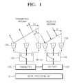
- FIG. 1illustrates an example of a configuration of a radar apparatus in accordance with the related art
- the radar apparatus in accordance with the related art illustrated in FIG. 1adopts a structure in which a transmitter 103 can perform beamforming and time division and a receiver 107 can receive nine channel data to reduce the number of antennas 104 and 105 , thereby implementing miniaturization.
- the radar apparatus in accordance with the related art illustrated in FIG. 1may perform only one of the long range radar operation or the short range radar operation and thus, cannot simultaneously implement the long and short range radar modes.
- the radar apparatus in accordance with the related art of FIG. 1adopts a structure of using a switch to sequentially receive signal from an array antenna.
- the switchneeds to have excellent isolation characteristics. These characteristics can be implemented only by a compound element.
- the current CMOS technologyis hard to implement the excellent isolation characteristics, such that there is a limitation in implementing the transmitting and receiving radar apparatus in a single chip type by using the CMOS technology.
- the radar of the long range and short range applications for a vehiclehas been commercialized.
- the radaris expensive, consumes large power, and has a large volume, which leads to a limitation in being simultaneously mounted in the front, rear, and sides of all the vehicles.
- an SiGe technologyhas been used to implement miniaturization through integration, but makes it more difficult to implement low power consumption than the CMOS technology and has a limitation in implementing miniaturization or low price due to a large antenna.
- An embodiment of the present inventionis directed to a radar apparatus supporting short and long range radar operations capable of implementing miniaturization, high integration, and low power consumption by implementing most components in the radar apparatus on a single chip while supporting a short range radar operation and a long range radar operation by a single apparatus or system configuration.
- a radar apparatus supporting long range and short range radar operationswherein a plurality of short range transmitting chirp signals and a plurality of long range transmitting chirp signals are generated by a predetermined modulation scheme and is transmitted to an object through at least one transmitting array antenna and signals reflected from the object is received through at least one receiving array antenna, and the plurality of long range transmitting chirp signals have transmission power larger than that for the plurality of short range transmitting chirp signals.
- the predetermined modulation schememay adopt at least one frequency modulated continuous-wave (FMCW) modulation scheme for detecting multi targets.
- FMCWfrequency modulated continuous-wave
- the plurality of long range transmitting chirp signals and the plurality of short range transmitting chirp signalsmay include a plurality of chirp signals having different slopes of frequency with respect to time, respectively, for detecting multi targets.
- the plurality of long range transmitting chirp signalsmay include at least six chirp signals having different slopes of frequency with respect to time and the plurality of long range transmitting chirp signals may include at least four chirp signals having different slopes of frequency with respect to time.
- the radar apparatusmay include: an antenna unit configured to include the at least one transmitting array antenna and the at least one receiving array antenna; a transmitter configured to generate the plurality of long range transmitting chirp signals and the plurality of short range transmitting chirp signals and transmit the generated chirp signals through the at least one transmitting array antenna; a receiver configured to process the reflected signal received through the at least one receiving array antenna; and a signal processing processor configured to generate control signals for generating the plurality of short range transmitting chirp signals and the plurality of long term transmitting chirp signals and process the signals processed through the receiver.
- the transmittermay include at least two power amplifiers configured to differently output the transmission power for the plurality of long range transmitting chirp signals and the transmission power for the plurality of short range transmitting chirp signals.
- the power amplifiermay vary the transmitting power into two-stage or more according to an operating mode for easily controlling the detection range.
- the transmittermay include: a frequency synthesizer configured to synthesize a frequency based on the control signals; an oscillator configured to receive an output of the frequency synthesizer to generate a carrier signal; a frequency multiplier configured to perform frequency multiplication on the output signal of the oscillator; a driver configured to drive an signal of the frequency multiplier; and at least two power amplifier configured to amplify the output signal of the driver to differently output the transmission power for the plurality of short range transmitting chirp signals and the transmission power for the plurality of long range transmitting chirp signals.
- the at least two power amplifiersmay be a variable gain amplifier.
- the receivermay include a plurality of receiving units, wherein each receiving unit includes: a low noise amplifier configured to amplify the received reflected wave signal; a down converting mixer configured to remove carrier component from an output of the low noise amplifier; and a filter configured to remove noise from an output of the down converting mixer.
- the transmitter and the receivermay be implemented on a single chip by a CMOS technology.
- the transmitter and the receiver, and the signal processing processormay be implemented on three chips of a transmitting chip, a receiving chip, and a signal processing unit chip, two chips of a transmitting and receiving chip and a signal processing unit chip, or a single chip on which the transmitting and receiving chip and the signal processing unit chip are integrated by the CMOS technology.
- the at least one transmitting and receiving array antennasmay be fabricated on a low temperature co-fired ceramics (LTCC) substrate so as to be miniaturized.
- LTCClow temperature co-fired ceramics
- the at least one receiving array antennamay be a plurality of phase array antennas that detect an azimuth angle of the object.
- FIG. 1illustrates an example of a configuration of a radar apparatus in accordance with the related art
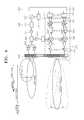
- FIG. 2is a diagram illustrating a configuration of a radar apparatus simultaneously supporting short range and long range radar operations in accordance with the embodiment of the present invention
- FIG. 3is a diagram illustrating a plurality of short range transmitting chirp signals and a plurality of long range transmitting chirp signals that are transmitted from a radar apparatus in accordance with the embodiment of the present invention.
- FIG. 4is a conceptual diagram for describing signals radiated and reflected and received from the radar apparatus in accordance with the embodiment of the present invention.
- FIG. 2is a diagram illustrating a configuration of a radar apparatus simultaneously supporting short range and long range radar operations in accordance with the embodiment of the present invention
- FIG. 3is a diagram illustrating a plurality of short range transmitting chirp signals and a plurality of long range transmitting chirp signals that are transmitted from a radar apparatus in accordance with the embodiment of the present invention
- FIG. 4is a conceptual diagram for describing signals radiated and reflected and received from the radar apparatus in accordance with the embodiment of the present invention.
- a radar apparatus simultaneously supporting short range and long range radar operationsin accordance with an embodiment of the present invention generates a plurality of short range transmitting chirp signals and a plurality of long range transmitting chirp signals by a frequency modulated continuous-wave (FMCW) modulation scheme and transmits the generated chirp signals to an object (not illustrated) through at least one transmitting array antenna 211 and receives a signal reflected from an object through at least one receiving array antenna 212 , wherein the plurality of long range transmitting chirp signal has transmit power larger than that of the plurality of short range transmitting chirp signals.
- FMCWfrequency modulated continuous-wave
- the radar apparatusmay be configured to include: an antenna unit 210 including the at least one transmitting array antenna 211 and the at least one receiving array antenna 212 ; a transmitter 220 generating the plurality of short range transmission chirp signals and the plurality of long range transmitting chirp signals by the FMCW modulation scheme and transmitting the generated chirp signals through the at least one transmitting array antenna 211 ; a receiver 240 processing a reflected wave signal received through the at least one receiving array antenna 212 ; and a signal processing processor 231 generating a control signal for generating the plurality of short range transmitting chirp signals and the plurality of long range transmitting chirp signals and processing the signals processed by the receiver 240 .
- the transmitter 220is configured to include: a frequency synthesizer synthesizing a frequency based on the control signal; an oscillator 222 receiving an output of the frequency synthesizer 221 and generating a carrier signal; a frequency multiplier 223 performing frequency multiplication on an output signal of the oscillator 222 ; a driver 225 driving an signal of the frequency multiplier 223 ; and at least two power amplifiers 226 amplifying an output signal of the driver 225 and outputting different transmission power for the plurality of short range transmitting chirp signals and the plurality of long range transmitting chirp signals.
- the power amplifiers 226may be designed such that the transmitting power can be varied into two-stage or more in order to easily control the detection range on the long range mode and the short range mode.
- the receiver 240includes a plurality of receiving units, wherein each receiving unit includes a low noise amplifier 241 amplifying the received reflected wave signal; a down converting mixer 242 removing carrier components from the output of the low noise amplifier 241 ; and a filter 243 removing noise from the output of the down converting mixer 242 .
- the radar apparatus in accordance with the embodiment of the present inventionhas the following configuration. That is, the radar apparatus in accordance with the embodiment of the present invention include a structural feature such as i) a new frequency modulated continuous-wave (FMCW) modulation scheme, ii) a control of transmission power for controlling a detection range, and iii) a combination of an antenna for controlling a field of view and a power amplifier, and the like.
- FMCWnew frequency modulated continuous-wave
- the radar apparatusin accordance with the embodiment of the present invention generates the plurality of short range transmitting chirp signals and the plurality of long range transmitting chirp signals by the FMCW modulation scheme and transmits the generated chirp signals to an object (not illustrated) through at least one transmitting array antenna 211 .
- the signal processing processor 231 included in the signal processing unit 230first generates control signals for generating the plurality of short range transmitting chirp signals and the plurality of long range transmitting chirp signals and transmits the generated control signals to the transmitter 220 .
- the modulation schemethe at least one frequency modulated continuous-wave (FMCW) modulation scheme may be adopted for detecting the multi targets.
- FMCWfrequency modulated continuous-wave
- the frequency synthesizer 221 of the transmitter 220synthesizes and outputs the frequency based on the control signal.
- the frequency synthesizer 221may use, for example, a direct digital frequency synthesizer (DDFS).
- DDFSdirect digital frequency synthesizer
- the oscillator 222receives the output of the frequency synthesizer 221 to generate the carrier signals, wherein as the oscillator 222 , a voltage controlled oscillator (VCO) may be used.
- the frequency multiplier 223multiplies and outputs the output signal of the oscillator 222 .
- the frequency multiplier 223is an element outputting a frequency that is an integer time of the input frequency.
- the frequency multiplier 223 in accordance with the embodiment of the present inventionmay in particular multiply and output the frequency twice.
- a drive amplifier 224amplifies and outputs the output signal of the frequency multiplier 223 .
- the driver 225provides the output signal of the frequency multiplier 223 to a driving power amplifier 226 and also provides the output signal to the driver amplifier 227 .
- the power amplifier 226amplifies the output signal of the driver 225 and outputs the transmitting array antenna 211 of the antenna unit 210 .
- at least two power amplifiers 226may be applied as illustrated in FIG. 2 .
- the two power amplifiers ( 226 )each has different amplification factor, which is to make the transmission power for the short range chirp signal and the long range transmitting chirp signal different as described below.
- the power amplifier 226may be a variable gain amplifier that can vary and control the amplification factor.
- the plurality of short range transmitting chirp signals and the plurality of long range transmitting chirp signalsare generated by the transmitter 220 via the processes.
- the plurality of chirp signals for the short range radar (SRR) operationinclude four chirp signals 50 , 51 , 52 , and 53 having different slopes of frequency with respect to time and the transmission power 60 for the short range transmission has relatively lower and mainly targets objects that are positioned within the a range of about 60 m or less. Further, as illustrated in FIG.
- the plurality of chirp signals for the long range radar (SRR) operationinclude six chirp signals 54 , 55 , 56 , 57 , 58 , and 59 having different slopes of frequency with respect to time and the transmission power 61 for the long range transmission has relatively higher than that for the short range transmitting chirp signal and mainly targets objects that are positioned within a distance of the range of about 150 m or less.
- SRRlong range radar
- the short range transmitting chirp signalis amplified by the amplifier having the relatively lower amplification factor among the two power amplifiers 226 as illustrated in FIG. 2 and the long range transmitting chirp signal is amplified by the amplifier having the relatively higher amplification factor among the two power amplifiers 226 , such that they may have the transmission output as illustrated in FIG. 3 .
- the generated plurality of short range transmitting chirp signals and plurality of long range transmitting chirp signalsare radiated to objects through the transmitting array antenna 211 .
- the short range transmitting chirp signalsneeds to be radiated to have the wider field of view with respect to the relatively shorter distance range and the long range transmitting chirp signals needs to be radiated to have the narrower field of view with respect to the relatively longer distance range.
- one of the transmitting array antennas 211may be designed to widen the field of view of the antenna that means the detectable angle range and the other one thereof may be designed to narrow the field of view of the antenna.
- FIG. 4is a conceptual diagram for describing signals radiated and reflected and received from the radar apparatus in accordance with the embodiment of the present invention. As illustrated in FIG. 4 , the short range transmitting chirp signals are radiated to have the wide field of view with respect to the relatively shorter distance range and the long range transmitting chirp signals are radiated to have the narrow field of view with respect to the relatively longer distance range and then, received through the receiving array antenna 212 .
- the embodiment of the present inventiongenerates the transmitting signal using the FMCW modulation scheme but generates the plurality of short range transmitting chirp signals and the plurality of long range transmitting chirp signals having different slopes of frequency with respect to time and makes the transmission power for the long range transmitting chirp signals larger than that for the short range transmitting chirp signals, such that the single radar apparatus can implement both of the short range radar operation and the long range radar operation.
- the radar apparatus according to the embodiment of the present inventionmay have a long detection range and a narrow detection angle and have good resolution for the detection angle at the time of sensing the long range and have a short detection range and a wide detection angle and have excellent resolution for the detection range.
- the transmitted chirp signalsare reflected by an object and the plurality of receiving array antennas 212 receive signals reflected from an object.
- the receiving array antenna 212includes at least eight antenna elements and the plurality of receiving units connected thereto as illustrated in FIG. 2 .
- the receiving antenna in accordance with the embodiment of the present inventionis a phase array antenna, which can detect an azimuth angle of the object.
- Each receiving unitmay include a low noise amplifier 241 , a down converting mixer 242 , a filter 243 , and a variable gain amplifier 244 that are connected to the antenna elements, respectively.
- the low noise amplifier 241amplifies and outputs the reflected wave signal received by the receiving array antenna 212 .
- a variable gain I/Q low noise amplifiermay be applied.
- the down converting mixer 242removes and outputs the carrier component from the output signal of the low noise amplifier 241 .
- the filter 243removes and outputs noise from the output signal of the down converting mixer 242 and the variable gain amplifier (VGA) 244 amplifies the output signal and outputs the amplified output signal to the signal processing unit 230 .
- VGAvariable gain amplifier
- an analog-digital converter (ADC) 232 of the signal processing unit 230converts the provided signals from an analog form into a digital form and provides the converted signals to the signal processing processor 231 .
- the signal processing processor 231receives signals from the receiving array antenna 212 that is the phase array antenna and receives the signals provided via the plurality of receiving units of the receiver 240 and performs the signal processing thereon, thereby performing a work such as a location detection (an azimuth angle detection of an object), and the like.
- the transmitting and receiving array antennas in accordance with the embodiment of the present inventionmay be manufactured on a low temperature co-fired ceramics (LTCC) substrate, which can be configured as the small and slim apparatus.
- LTCClow temperature co-fired ceramics
- the embodiment of the present inventiongenerates the plurality of short range transmitting chirp signals and the plurality of long range transmitting chirp signals having different slopes of frequency with respect to time and makes the transmission power for the long range transmitting chirp signals larger than that for the short range transmitting chirp signals, such that the single radar apparatus can implement both of the short range radar operation and the long range radar operation. Further, as describe above, the embodiment of the present invention differently sets the amplification factors of the plurality of power amplifiers 226 so as to perform the long range radar operation and the short range radar operation and thus, does not use a separate switch device.
- the embodiment of the present inventioncan implement the transmitter 220 , the receiver 240 , and the signal processing unit 230 including the signal processing processor 231 within the radar apparatus on the single chip by the CMOS technology. Therefore, the radar apparatus in accordance with the embodiment of the present invention can achieve miniaturization, high integration, and low power consumption by implementing most components in the radar apparatus on the single chip while supporting the short range radar operation and a long range radar operation.
- the transmitter and the receiver, and the signal processing processormay be implemented on three chips of a transmitting chip, a receiving chip, and a signal processing unit chip, two chips of a transmitting and receiving chip and a signal processing unit chip, or a single chip on which the transmitting and receiving chip and the signal processing unit chip are integrated
- the transmitting and receiving array antenna in accordance with the embodiment of the present inventionis manufactured on the LTCC substrate and then, is applied with a flip chip package technology, which can be implemented as the small and slim apparatus.
- the radar apparatus in accordance with the embodiments of the present inventioncan achieve miniaturization, high integration, and low power consumption by implementing most components in the radar apparatus on the single chip while supporting the short range radar operation and a long range radar operation by the single apparatus or system configuration.
Landscapes
- Engineering & Computer Science (AREA)
- Radar, Positioning & Navigation (AREA)
- Remote Sensing (AREA)
- Physics & Mathematics (AREA)
- Computer Networks & Wireless Communication (AREA)
- General Physics & Mathematics (AREA)
- Electromagnetism (AREA)
- Signal Processing (AREA)
- Radar Systems Or Details Thereof (AREA)
Abstract
Description
Claims (14)
Applications Claiming Priority (4)
| Application Number | Priority Date | Filing Date | Title |
|---|---|---|---|
| KR20110023592 | 2011-03-16 | ||
| KR10-2011-0023592 | 2011-03-16 | ||
| KR1020120023430AKR20120106567A (en) | 2011-03-16 | 2012-03-07 | Radar apparatus supporting short and long range radar operation |
| KR10-2012-0023430 | 2012-03-07 |
Publications (2)
| Publication Number | Publication Date |
|---|---|
| US20120235857A1 US20120235857A1 (en) | 2012-09-20 |
| US8902103B2true US8902103B2 (en) | 2014-12-02 |
Family
ID=46813177
Family Applications (1)
| Application Number | Title | Priority Date | Filing Date |
|---|---|---|---|
| US13/421,223Active2032-11-20US8902103B2 (en) | 2011-03-16 | 2012-03-15 | Radar apparatus supporting short and long range radar operation |
Country Status (3)
| Country | Link |
|---|---|
| US (1) | US8902103B2 (en) |
| CN (1) | CN102680963B (en) |
| DE (1) | DE102012102185A1 (en) |
Cited By (25)
| Publication number | Priority date | Publication date | Assignee | Title |
|---|---|---|---|---|
| US20160124087A1 (en)* | 2014-09-05 | 2016-05-05 | GM Global Technology Operations LLC | Object boundary detection for automotive radar imaging |
| US20160223651A1 (en)* | 2015-01-29 | 2016-08-04 | Nidec Elesys Corporation | Neural network-based radar system having independent multibeam antenna |
| US20180059216A1 (en)* | 2016-08-26 | 2018-03-01 | Infineon Technologies Ag | Receive chain configuration for concurrent multi-mode radar operation |
| EP3267221A3 (en)* | 2016-06-14 | 2018-03-28 | MediaTek Inc. | Reconfigurable rf front end and antenna arrays for radar mode switching |
| US10033098B2 (en)* | 2013-04-03 | 2018-07-24 | Robert Bosch Gmbh | Radar device and method having an antenna array with two switching states of different modulation |
| US10067227B2 (en) | 2014-10-06 | 2018-09-04 | Nidec Corporation | Neural network-based radar system |
| US20190212438A1 (en)* | 2018-01-10 | 2019-07-11 | Mando Corporation | Apparatus and method for controlling radar |
| US20190219683A1 (en)* | 2018-01-15 | 2019-07-18 | Metawave Corporation | Method and apparatus for radar waveforms using orthogonal sequence sets |
| CN110068812A (en)* | 2019-05-06 | 2019-07-30 | 成都泰格微电子研究所有限责任公司 | A kind of low-power consumption millimetre-wave radar detecting module |
| US10366603B2 (en)* | 2017-10-02 | 2019-07-30 | Toyota Jidosha Kabushiki Kaisha | Recognition support device for vehicle |
| US20200103498A1 (en)* | 2018-10-02 | 2020-04-02 | Metawave Corporation | Adaptive radar for near-far target identification |
| US10630249B2 (en)* | 2017-08-04 | 2020-04-21 | Texas Instruments Incorporated | Low power mode of operation for mm-wave radar |
| US10712437B2 (en) | 2017-07-07 | 2020-07-14 | Veoneer Us, Inc. | Radar systems and methods utilizing composite waveforms for customization of resolution requirements |
| US10901082B2 (en)* | 2017-11-09 | 2021-01-26 | Fractal Antenna Systems, Inc. | Road identification system using enhanced cross-section targets |
| US20210096212A1 (en)* | 2018-06-25 | 2021-04-01 | Socionext Inc. | Frequency sweep circuit and radar device |
| US11041958B2 (en)* | 2017-04-28 | 2021-06-22 | SZ DJI Technology Co., Ltd. | Sensing assembly for autonomous driving |
| US11073607B2 (en)* | 2018-11-28 | 2021-07-27 | Lockheed Martin Corporation | Wideband radar systems, apparatuses, and methods |
| US20210349200A1 (en)* | 2018-10-05 | 2021-11-11 | Kyocera Corporation | Electronic device, control method of electronic device, and control program of electronic device |
| US11214247B2 (en)* | 2019-04-26 | 2022-01-04 | Toyota Jidosha Kabushiki Kaisha | Vehicle control device |
| US20220003858A1 (en)* | 2018-09-27 | 2022-01-06 | Kyocera Corporation | Electronic apparatus, control method for electronic apparatus, and control program for electronic apparatus |
| US20220206108A1 (en)* | 2020-12-28 | 2022-06-30 | Bitsensing Inc. | Radar apparatus and method for detecting object based on multiple modes |
| US11579246B2 (en)* | 2019-03-11 | 2023-02-14 | Hl Klemove Corp. | Radar apparatus, antenna device for radar apparatus, and control method of radar apparatus |
| US20230138631A1 (en)* | 2020-04-10 | 2023-05-04 | Mitsubishi Electric Corporation | Radar device |
| US11650303B2 (en) | 2017-04-25 | 2023-05-16 | Audi Ag | Method for operating a radar sensor in a motor vehicle, radar sensor, and motor vehicle |
| US12235346B2 (en) | 2021-01-29 | 2025-02-25 | Electronics And Telecommunications Research Institute | Radar device operating in dual mode and operation method thereof |
Families Citing this family (65)
| Publication number | Priority date | Publication date | Assignee | Title |
|---|---|---|---|---|
| JP5866917B2 (en)* | 2011-09-20 | 2016-02-24 | 富士通株式会社 | Detecting and ranging apparatus and detecting and ranging method |
| US9275690B2 (en) | 2012-05-30 | 2016-03-01 | Tahoe Rf Semiconductor, Inc. | Power management in an electronic system through reducing energy usage of a battery and/or controlling an output power of an amplifier thereof |
| US9509351B2 (en) | 2012-07-27 | 2016-11-29 | Tahoe Rf Semiconductor, Inc. | Simultaneous accommodation of a low power signal and an interfering signal in a radio frequency (RF) receiver |
| US9184498B2 (en) | 2013-03-15 | 2015-11-10 | Gigoptix, Inc. | Extending beamforming capability of a coupled voltage controlled oscillator (VCO) array during local oscillator (LO) signal generation through fine control of a tunable frequency of a tank circuit of a VCO thereof |
| US9531070B2 (en) | 2013-03-15 | 2016-12-27 | Christopher T. Schiller | Extending beamforming capability of a coupled voltage controlled oscillator (VCO) array during local oscillator (LO) signal generation through accommodating differential coupling between VCOs thereof |
| US9722310B2 (en) | 2013-03-15 | 2017-08-01 | Gigpeak, Inc. | Extending beamforming capability of a coupled voltage controlled oscillator (VCO) array during local oscillator (LO) signal generation through frequency multiplication |
| US9666942B2 (en) | 2013-03-15 | 2017-05-30 | Gigpeak, Inc. | Adaptive transmit array for beam-steering |
| US9780449B2 (en) | 2013-03-15 | 2017-10-03 | Integrated Device Technology, Inc. | Phase shift based improved reference input frequency signal injection into a coupled voltage controlled oscillator (VCO) array during local oscillator (LO) signal generation to reduce a phase-steering requirement during beamforming |
| US9837714B2 (en) | 2013-03-15 | 2017-12-05 | Integrated Device Technology, Inc. | Extending beamforming capability of a coupled voltage controlled oscillator (VCO) array during local oscillator (LO) signal generation through a circular configuration thereof |
| US9716315B2 (en) | 2013-03-15 | 2017-07-25 | Gigpeak, Inc. | Automatic high-resolution adaptive beam-steering |
| DE102013215117A1 (en)* | 2013-08-01 | 2015-02-05 | Robert Bosch Gmbh | Object determination by means of radar sensor |
| KR20150017976A (en)* | 2013-08-08 | 2015-02-23 | 주식회사 만도 | Vehichl radar and operating method of it |
| US9383442B2 (en)* | 2014-05-12 | 2016-07-05 | Autoliv Asp, Inc. | Radar system and method for determining range, relative velocity and bearing of an object using continuous-wave and chirp signals |
| DE102014212281A1 (en)* | 2014-06-26 | 2015-12-31 | Robert Bosch Gmbh | Radar measurement with different viewing areas |
| DE102014009861B4 (en)* | 2014-07-03 | 2021-06-24 | Audi Ag | Radar sensor device with at least two radar sensors and a motor vehicle |
| DE102014009869A1 (en)* | 2014-07-03 | 2016-01-21 | Audi Ag | Method for operating a radar sensor in a motor vehicle and motor vehicle |
| DE102014010387A1 (en)* | 2014-07-12 | 2016-01-14 | Audi Ag | Method for determining the speed of a motor vehicle from radar data of a single radar sensor and motor vehicle |
| DE102014010381A1 (en)* | 2014-07-12 | 2016-01-14 | Audi Ag | Method for operating a vehicle system of a motor vehicle for protection against damage caused by unevenness of the ground and motor vehicle |
| DE102015007040B4 (en)* | 2015-05-30 | 2020-09-24 | Audi Ag | Method for the detection and classification of pedestrians in the surroundings of a motor vehicle and motor vehicle |
| DE102015007034B4 (en)* | 2015-05-30 | 2022-01-27 | Audi Ag | Method for operating a parking assistance system of a motor vehicle and motor vehicle |
| KR102435550B1 (en)* | 2015-06-09 | 2022-08-24 | 주식회사 에이치엘클레무브 | Apparatur for processing signal of radar and method for processing signal thereof |
| KR102378478B1 (en)* | 2015-08-31 | 2022-03-25 | 엘지이노텍 주식회사 | Radar module and automotive radar apparatus having the same |
| KR101760907B1 (en)* | 2015-11-20 | 2017-07-24 | 주식회사 만도 | Radar apparatus for vehicle and method for measuring target of the same |
| KR101890352B1 (en)* | 2015-12-11 | 2018-08-21 | 주식회사 만도 | Radar apparatus for vehicle and method for removing ghost of the same |
| US10151826B2 (en) | 2016-02-16 | 2018-12-11 | Infineon Technologies Ag | Radar employing preacquisition ramps |
| US10847879B2 (en)* | 2016-03-11 | 2020-11-24 | Huawei Technologies Canada Co., Ltd. | Antenna array structures for half-duplex and full-duplex multiple-input and multiple-output systems |
| US9846228B2 (en)* | 2016-04-07 | 2017-12-19 | Uhnder, Inc. | Software defined automotive radar systems |
| US11002829B2 (en)* | 2016-04-15 | 2021-05-11 | Mediatek Inc. | Radar interference mitigation method and apparatus |
| KR102589762B1 (en)* | 2016-06-20 | 2023-10-17 | 주식회사 에이치엘클레무브 | Radar apparatus and Method for processing radar signal |
| US11588567B2 (en)* | 2016-12-02 | 2023-02-21 | Texas Instruments Incorporated | Synchronizing vehicle devices over a controller area network |
| KR20180092134A (en)* | 2017-02-08 | 2018-08-17 | 주식회사 만도 | A radar having a structure capable of suppressing low-frequency noise |
| US10473775B2 (en)* | 2017-03-20 | 2019-11-12 | David Slemp | Frequency modulated continuous wave antenna system |
| US11372096B2 (en)* | 2017-03-20 | 2022-06-28 | David Slemp | Frequency modulated continuous wave antenna system |
| JP6799494B2 (en)* | 2017-04-27 | 2020-12-16 | 日立オートモティブシステムズ株式会社 | Radar circuits, radar systems, and radar programs |
| CN108872951B (en)* | 2017-05-12 | 2021-08-10 | 比亚迪股份有限公司 | Automobile and modulation method and modulation system of automobile FMCW radar |
| CN107356919A (en)* | 2017-07-04 | 2017-11-17 | 上海通趣科技有限公司 | The radar and its length distance measurement method of length distance measurement can be carried out simultaneously |
| CN107688178A (en)* | 2017-08-25 | 2018-02-13 | 上海通趣科技有限公司 | A kind of sawtooth waveforms ranging and range rate method based on 77GHz millimetre-wave radars |
| KR102401176B1 (en)* | 2017-09-14 | 2022-05-24 | 삼성전자주식회사 | Radar image processing method, apparatus and system |
| US10852390B2 (en)* | 2017-12-20 | 2020-12-01 | Waymo Llc | Multiple polarization radar unit |
| US10326420B1 (en) | 2018-03-21 | 2019-06-18 | Globalfoundries Inc. | Receiver circuits for millimeter wave devices |
| CN108196255A (en)* | 2018-03-23 | 2018-06-22 | 加特兰微电子科技(上海)有限公司 | Millimeter wave radar system for vehicle |
| US11567168B2 (en)* | 2018-04-02 | 2023-01-31 | Maxlinear, Inc. | Gain control in an orthogonal frequency division multiplexed radar system |
| US11047956B2 (en)* | 2018-06-14 | 2021-06-29 | Semiconductor Components Industries, Llc | Reconfigurable MIMO radar |
| JPWO2020049648A1 (en)* | 2018-09-05 | 2021-08-12 | 株式会社ソシオネクスト | Sensing method and sensing device |
| CN112789518A (en)* | 2018-10-12 | 2021-05-11 | 京瓷株式会社 | Electronic device, control method for electronic device, and control program for electronic device |
| CN111505641B (en) | 2019-01-30 | 2023-01-13 | 华为技术有限公司 | Radio signal transmission method and apparatus |
| WO2020183392A1 (en) | 2019-03-12 | 2020-09-17 | Uhnder, Inc. | Method and apparatus for mitigation of low frequency noise in radar systems |
| CN113631945A (en)* | 2019-03-20 | 2021-11-09 | 京瓷株式会社 | Electronic device, control method of electronic device, and control program of electronic device |
| JP7174668B2 (en)* | 2019-04-25 | 2022-11-17 | 京セラ株式会社 | ELECTRONIC DEVICE, ELECTRONIC DEVICE CONTROL METHOD, AND ELECTRONIC DEVICE CONTROL PROGRAM |
| CN112133999B (en)* | 2019-06-24 | 2025-03-25 | 户外无线网络有限公司 | Base station antenna |
| WO2021003440A1 (en) | 2019-07-02 | 2021-01-07 | Metawave Corporation | Beam steering radar with selective scanning mode for autonomous vehicles |
| US11221395B2 (en)* | 2019-08-12 | 2022-01-11 | GM Global Technology Operations LLC | Chip-based transmit channel architecture |
| US11714183B2 (en)* | 2019-09-03 | 2023-08-01 | Nxp B.V. | Impulse radar using variable pulse repetition frequency |
| US11444377B2 (en)* | 2019-10-03 | 2022-09-13 | Aptiv Technologies Limited | Radiation pattern reconfigurable antenna |
| CN110927705A (en)* | 2019-11-26 | 2020-03-27 | 北京工业大学 | Design of a 77GHz Millimeter Wave Circuit |
| CN111077516B (en)* | 2019-12-31 | 2024-08-09 | 西安天和防务技术股份有限公司 | Ground monitoring radar and detection method |
| US11953615B2 (en) | 2020-01-13 | 2024-04-09 | Uhnder Inc. | Method and system for antenna array calibration for cross-coupling and gain/phase variations in radar systems |
| JP7390657B2 (en)* | 2020-03-18 | 2023-12-04 | パナソニックIpマネジメント株式会社 | radar equipment |
| EP4012443A1 (en)* | 2020-12-08 | 2022-06-15 | Veoneer Sweden AB | A vehicle radar system |
| IL279407A (en)* | 2020-12-13 | 2022-07-01 | Qualcomm Inc | Multimode radar system |
| US12276719B2 (en) | 2021-03-31 | 2025-04-15 | Denso Corporation | Radar device and signal processing method of radar device |
| US11947032B2 (en)* | 2021-07-02 | 2024-04-02 | Kabushiki Kaisha Toshiba | Radar limiter distortion cancellation |
| CN114035233B (en)* | 2021-11-30 | 2024-09-03 | 武汉声赫科技有限公司 | Stepping frequency phased array ground penetrating radar receiving and transmitting system |
| CN114814845A (en)* | 2022-04-20 | 2022-07-29 | 江苏集萃深度感知技术研究所有限公司 | Millimeter wave radar road detection system and method |
| US20240272278A1 (en)* | 2023-02-14 | 2024-08-15 | Microsoft Technology Licensing, Llc | Pose detection using multi-chirp fmcw radar |
Citations (54)
| Publication number | Priority date | Publication date | Assignee | Title |
|---|---|---|---|---|
| US3344426A (en)* | 1965-12-01 | 1967-09-26 | Raytheon Co | Radar system |
| US3451059A (en)* | 1950-06-08 | 1969-06-17 | Robert M Page | Echo ranging system of variable sensitivity and variable range resolution |
| US3728724A (en)* | 1971-02-12 | 1973-04-17 | Us Navy | Adaptive swept-frequency active radar seeker |
| US3945011A (en)* | 1973-11-13 | 1976-03-16 | The Marconi Company Limited | Radar system employing consecutive pulses only one of which is frequency swept |
| US4136341A (en)* | 1976-11-12 | 1979-01-23 | Hollandse Signaalappareten, B.V. | Radar system employing two kinds of pulses |
| US4404562A (en)* | 1980-08-25 | 1983-09-13 | The United States Of America As Represented By The Secretary Of The Navy | Low sidelobe linear FM chirp system |
| US4490720A (en)* | 1981-03-30 | 1984-12-25 | The Bendix Corporation | Multipulse signal processing for radar system |
| US4524361A (en)* | 1981-05-05 | 1985-06-18 | Hollandse Signaalapparaten B.V. | Radar systems employing two kinds of pulses |
| US4573050A (en)* | 1983-02-17 | 1986-02-25 | The United States Of America As Represented By The Secretary Of The Navy | Dual scan rate radar |
| US4983979A (en)* | 1989-03-28 | 1991-01-08 | Canadian Marconi Company | Radar detection of targets at short and long range |
| US5128681A (en)* | 1991-06-27 | 1992-07-07 | United Technologies Corporation | Multi-pulse pulse compression radar system |
| US5140332A (en)* | 1989-07-13 | 1992-08-18 | Westinghouse Electric Corp. | Short pulse radar system with a long pulse transmitter |
| US5652589A (en)* | 1994-11-08 | 1997-07-29 | Honda Giken Kogyo Kabushiki Kaisha | FM-CW multibeam radar apparatus |
| US5734345A (en)* | 1996-04-23 | 1998-03-31 | Trw Inc. | Antenna system for controlling and redirecting communications beams |
| US5959578A (en)* | 1998-01-09 | 1999-09-28 | Motorola, Inc. | Antenna architecture for dynamic beam-forming and beam reconfigurability with space feed |
| US6047244A (en)* | 1997-12-05 | 2000-04-04 | Rosemount Inc. | Multiple range transition method and apparatus for process control sensors |
| US6507311B2 (en) | 2000-05-25 | 2003-01-14 | Bayerische Motoren Werke Aktiengesellschaft | Device and process for measuring distance and speed |
| US6509863B2 (en)* | 1999-08-06 | 2003-01-21 | Visteon Corporation | Radar-field-of-view enhancement method and apparatus for matching field-of-view to desired detection zone |
| US6580385B1 (en)* | 1999-05-26 | 2003-06-17 | Robert Bosch Gmbh | Object detection system |
| US6606052B1 (en) | 2002-03-07 | 2003-08-12 | Visteon Global Technologies, Inc. | Method and apparatus for detecting multiple objects with frequency modulated continuous wave radar |
| US20030164791A1 (en)* | 2001-12-18 | 2003-09-04 | Hitachi, Ltd. | Monopulse radar system |
| US6646589B2 (en)* | 2001-09-17 | 2003-11-11 | Denso Corporation | Radar designed to minimize error in detecting target |
| US6816084B2 (en)* | 2000-02-18 | 2004-11-09 | Daimlerchrysler Ag | Process and device for detecting and monitoring a number of preceding vehicles |
| US6844842B2 (en)* | 2000-08-16 | 2005-01-18 | Automotive Distance Control Systems Gmbh | Method for pulse width modulation of a radar system |
| US20050156780A1 (en)* | 2004-01-16 | 2005-07-21 | Ghz Tr Corporation | Methods and apparatus for automotive radar sensors |
| US20050179582A1 (en)* | 2000-08-16 | 2005-08-18 | Raytheon Company | Radar detection method and apparatus |
| US6933881B2 (en)* | 2003-04-23 | 2005-08-23 | Hitachi, Ltd. | Automotive radar |
| US6972711B2 (en)* | 2003-03-25 | 2005-12-06 | Fujitsu Ten Limited | Transmit-receive FM-CW radar apparatus |
| US7081847B2 (en)* | 2003-10-10 | 2006-07-25 | Valeo Schalter Und Sensoren | Radar system with switchable angular resolution |
| US7132976B2 (en)* | 2005-01-20 | 2006-11-07 | Hitachi, Ltd. | Automotive radar |
| US20060262007A1 (en)* | 2004-01-16 | 2006-11-23 | Clariant Technologies, Corp. | Methods and apparatus for automotive radar sensors |
| US20070205938A1 (en)* | 2000-03-08 | 2007-09-06 | Uwe Zimmermann | Object Detection System |
| US7268722B2 (en)* | 2002-12-24 | 2007-09-11 | Robert Bosch Gmbh | Angular resolution antenna system |
| US7275431B2 (en)* | 2002-12-13 | 2007-10-02 | Robert Bosch Gmbh | Vehicle mounted system for detecting objects |
| CN101076741A (en) | 2004-12-13 | 2007-11-21 | 罗伯特·博世有限公司 | Radar system with adaptive digital reception beam forming and switchable transmission directional characteristics for coverage of near and far range |
| US20080018526A1 (en)* | 2005-01-19 | 2008-01-24 | Smiths Group Plc | Radar Apparatus |
| US20080100500A1 (en)* | 2006-10-31 | 2008-05-01 | Hitachi, Ltd. | Radar, radio frequency sensor, and radar detection method |
| US20080165049A1 (en)* | 2007-01-09 | 2008-07-10 | Mitsubishi Electronic Corporation | Radar device |
| US20080278370A1 (en)* | 2007-05-09 | 2008-11-13 | Rudolf Lachner | Rf-frontend for a radar system |
| US7463185B2 (en)* | 2005-06-15 | 2008-12-09 | Murata Manufacturing Co., Ltd. | Radar apparatus having wide-angle detection |
| US7504988B2 (en)* | 2006-08-10 | 2009-03-17 | Fujitsu Ten Limited | Radar device with overlapping short and long range sensors |
| US7518545B2 (en)* | 2006-10-26 | 2009-04-14 | Infineon Technologies Ag | Driver assistance system |
| US20090201194A1 (en)* | 2008-02-12 | 2009-08-13 | Infineon Technologies Ag | Dual mode radar methods and systems |
| US7592945B2 (en)* | 2007-06-27 | 2009-09-22 | Gm Global Technology Operations, Inc. | Method of estimating target elevation utilizing radar data fusion |
| US20090267822A1 (en)* | 2008-04-28 | 2009-10-29 | Hitachi, Ltd. | Mobile radar and planar antenna |
| US7675457B2 (en)* | 2003-11-18 | 2010-03-09 | Murata Manufacturing Co., Ltd. | Radar system |
| KR100951529B1 (en) | 2007-12-21 | 2010-04-08 | 재단법인대구경북과학기술원 | Ultra wide band vehicle radar system driving method and ultra wide band vehicle radar system |
| US7773028B2 (en)* | 2006-12-06 | 2010-08-10 | Raytheon Company | Method and system for concatenation of radar pulses |
| US7786928B2 (en)* | 2004-09-13 | 2010-08-31 | Robert Bosch Gmbh | Monostatic planar multi-beam radar sensor |
| US7791530B2 (en)* | 2006-01-05 | 2010-09-07 | Autoliv Asp, Inc. | Time duplex apparatus and method for radar sensor front-ends |
| US20110267217A1 (en)* | 2004-09-25 | 2011-11-03 | Juergen Hildebrandt | Antenna radar system and method for its operation |
| US8405541B2 (en)* | 2010-09-01 | 2013-03-26 | Toyota Motor Engineering & Manufacturing North America, Inc. | Multi-range radar system |
| US8582085B2 (en)* | 2005-02-14 | 2013-11-12 | Digital Signal Corporation | Chirped coherent laser radar with multiple simultaneous measurements |
| US8624776B2 (en)* | 2007-08-31 | 2014-01-07 | Raymarine Uk Limited | Digital radar or sonar apparatus |
Family Cites Families (2)
| Publication number | Priority date | Publication date | Assignee | Title |
|---|---|---|---|---|
| KR101067026B1 (en) | 2009-08-31 | 2011-09-23 | 한국전자통신연구원 | System and method for configuring virtual network terminal device for customized network service |
| KR20120023430A (en) | 2010-09-03 | 2012-03-13 | 주식회사 이오테크닉스 | Method for detecting edges of wafer |
- 2012
- 2012-03-15USUS13/421,223patent/US8902103B2/enactiveActive
- 2012-03-15DEDE102012102185Apatent/DE102012102185A1/ennot_activeWithdrawn
- 2012-03-16CNCN201210174707.5Apatent/CN102680963B/ennot_activeExpired - Fee Related
Patent Citations (61)
| Publication number | Priority date | Publication date | Assignee | Title |
|---|---|---|---|---|
| US3451059A (en)* | 1950-06-08 | 1969-06-17 | Robert M Page | Echo ranging system of variable sensitivity and variable range resolution |
| US3344426A (en)* | 1965-12-01 | 1967-09-26 | Raytheon Co | Radar system |
| US3728724A (en)* | 1971-02-12 | 1973-04-17 | Us Navy | Adaptive swept-frequency active radar seeker |
| US3945011A (en)* | 1973-11-13 | 1976-03-16 | The Marconi Company Limited | Radar system employing consecutive pulses only one of which is frequency swept |
| US4136341A (en)* | 1976-11-12 | 1979-01-23 | Hollandse Signaalappareten, B.V. | Radar system employing two kinds of pulses |
| US4404562A (en)* | 1980-08-25 | 1983-09-13 | The United States Of America As Represented By The Secretary Of The Navy | Low sidelobe linear FM chirp system |
| US4490720A (en)* | 1981-03-30 | 1984-12-25 | The Bendix Corporation | Multipulse signal processing for radar system |
| US4524361A (en)* | 1981-05-05 | 1985-06-18 | Hollandse Signaalapparaten B.V. | Radar systems employing two kinds of pulses |
| US4573050A (en)* | 1983-02-17 | 1986-02-25 | The United States Of America As Represented By The Secretary Of The Navy | Dual scan rate radar |
| US4983979A (en)* | 1989-03-28 | 1991-01-08 | Canadian Marconi Company | Radar detection of targets at short and long range |
| US5140332A (en)* | 1989-07-13 | 1992-08-18 | Westinghouse Electric Corp. | Short pulse radar system with a long pulse transmitter |
| US5128681A (en)* | 1991-06-27 | 1992-07-07 | United Technologies Corporation | Multi-pulse pulse compression radar system |
| US5652589A (en)* | 1994-11-08 | 1997-07-29 | Honda Giken Kogyo Kabushiki Kaisha | FM-CW multibeam radar apparatus |
| US5734345A (en)* | 1996-04-23 | 1998-03-31 | Trw Inc. | Antenna system for controlling and redirecting communications beams |
| US6047244A (en)* | 1997-12-05 | 2000-04-04 | Rosemount Inc. | Multiple range transition method and apparatus for process control sensors |
| US5959578A (en)* | 1998-01-09 | 1999-09-28 | Motorola, Inc. | Antenna architecture for dynamic beam-forming and beam reconfigurability with space feed |
| US6580385B1 (en)* | 1999-05-26 | 2003-06-17 | Robert Bosch Gmbh | Object detection system |
| US6509863B2 (en)* | 1999-08-06 | 2003-01-21 | Visteon Corporation | Radar-field-of-view enhancement method and apparatus for matching field-of-view to desired detection zone |
| US6816084B2 (en)* | 2000-02-18 | 2004-11-09 | Daimlerchrysler Ag | Process and device for detecting and monitoring a number of preceding vehicles |
| US20070205938A1 (en)* | 2000-03-08 | 2007-09-06 | Uwe Zimmermann | Object Detection System |
| US6507311B2 (en) | 2000-05-25 | 2003-01-14 | Bayerische Motoren Werke Aktiengesellschaft | Device and process for measuring distance and speed |
| US7071868B2 (en)* | 2000-08-16 | 2006-07-04 | Raytheon Company | Radar detection method and apparatus |
| US20050179582A1 (en)* | 2000-08-16 | 2005-08-18 | Raytheon Company | Radar detection method and apparatus |
| US6844842B2 (en)* | 2000-08-16 | 2005-01-18 | Automotive Distance Control Systems Gmbh | Method for pulse width modulation of a radar system |
| US6646589B2 (en)* | 2001-09-17 | 2003-11-11 | Denso Corporation | Radar designed to minimize error in detecting target |
| US6853329B2 (en)* | 2001-12-18 | 2005-02-08 | Hitachi, Ltd. | Monopulse radar system |
| US6750810B2 (en)* | 2001-12-18 | 2004-06-15 | Hitachi, Ltd. | Monopulse radar system |
| US20030164791A1 (en)* | 2001-12-18 | 2003-09-04 | Hitachi, Ltd. | Monopulse radar system |
| US6606052B1 (en) | 2002-03-07 | 2003-08-12 | Visteon Global Technologies, Inc. | Method and apparatus for detecting multiple objects with frequency modulated continuous wave radar |
| US7275431B2 (en)* | 2002-12-13 | 2007-10-02 | Robert Bosch Gmbh | Vehicle mounted system for detecting objects |
| US7268722B2 (en)* | 2002-12-24 | 2007-09-11 | Robert Bosch Gmbh | Angular resolution antenna system |
| US6972711B2 (en)* | 2003-03-25 | 2005-12-06 | Fujitsu Ten Limited | Transmit-receive FM-CW radar apparatus |
| US6933881B2 (en)* | 2003-04-23 | 2005-08-23 | Hitachi, Ltd. | Automotive radar |
| US7081847B2 (en)* | 2003-10-10 | 2006-07-25 | Valeo Schalter Und Sensoren | Radar system with switchable angular resolution |
| US7675457B2 (en)* | 2003-11-18 | 2010-03-09 | Murata Manufacturing Co., Ltd. | Radar system |
| US20060262007A1 (en)* | 2004-01-16 | 2006-11-23 | Clariant Technologies, Corp. | Methods and apparatus for automotive radar sensors |
| US20050156780A1 (en)* | 2004-01-16 | 2005-07-21 | Ghz Tr Corporation | Methods and apparatus for automotive radar sensors |
| US7786928B2 (en)* | 2004-09-13 | 2010-08-31 | Robert Bosch Gmbh | Monostatic planar multi-beam radar sensor |
| US20110267217A1 (en)* | 2004-09-25 | 2011-11-03 | Juergen Hildebrandt | Antenna radar system and method for its operation |
| CN101076741A (en) | 2004-12-13 | 2007-11-21 | 罗伯特·博世有限公司 | Radar system with adaptive digital reception beam forming and switchable transmission directional characteristics for coverage of near and far range |
| US20080258964A1 (en)* | 2004-12-13 | 2008-10-23 | Thomas Schoeberl | Radar System |
| US20080018526A1 (en)* | 2005-01-19 | 2008-01-24 | Smiths Group Plc | Radar Apparatus |
| US7764223B2 (en)* | 2005-01-19 | 2010-07-27 | Kelvin Hughes Limited | Radar apparatus |
| US7132976B2 (en)* | 2005-01-20 | 2006-11-07 | Hitachi, Ltd. | Automotive radar |
| US8582085B2 (en)* | 2005-02-14 | 2013-11-12 | Digital Signal Corporation | Chirped coherent laser radar with multiple simultaneous measurements |
| US7463185B2 (en)* | 2005-06-15 | 2008-12-09 | Murata Manufacturing Co., Ltd. | Radar apparatus having wide-angle detection |
| US7791530B2 (en)* | 2006-01-05 | 2010-09-07 | Autoliv Asp, Inc. | Time duplex apparatus and method for radar sensor front-ends |
| US7504988B2 (en)* | 2006-08-10 | 2009-03-17 | Fujitsu Ten Limited | Radar device with overlapping short and long range sensors |
| US7518545B2 (en)* | 2006-10-26 | 2009-04-14 | Infineon Technologies Ag | Driver assistance system |
| US20080100500A1 (en)* | 2006-10-31 | 2008-05-01 | Hitachi, Ltd. | Radar, radio frequency sensor, and radar detection method |
| US7773028B2 (en)* | 2006-12-06 | 2010-08-10 | Raytheon Company | Method and system for concatenation of radar pulses |
| US20080165049A1 (en)* | 2007-01-09 | 2008-07-10 | Mitsubishi Electronic Corporation | Radar device |
| US20080278370A1 (en)* | 2007-05-09 | 2008-11-13 | Rudolf Lachner | Rf-frontend for a radar system |
| US7592945B2 (en)* | 2007-06-27 | 2009-09-22 | Gm Global Technology Operations, Inc. | Method of estimating target elevation utilizing radar data fusion |
| US8624776B2 (en)* | 2007-08-31 | 2014-01-07 | Raymarine Uk Limited | Digital radar or sonar apparatus |
| KR100951529B1 (en) | 2007-12-21 | 2010-04-08 | 재단법인대구경북과학기술원 | Ultra wide band vehicle radar system driving method and ultra wide band vehicle radar system |
| US20090201194A1 (en)* | 2008-02-12 | 2009-08-13 | Infineon Technologies Ag | Dual mode radar methods and systems |
| US7821443B2 (en)* | 2008-02-12 | 2010-10-26 | Infineon Technologies Ag | Dual mode radar methods and systems |
| US20090267822A1 (en)* | 2008-04-28 | 2009-10-29 | Hitachi, Ltd. | Mobile radar and planar antenna |
| US8009082B2 (en)* | 2008-04-28 | 2011-08-30 | Hitachi, Ltd. | Mobile radar and planar antenna |
| US8405541B2 (en)* | 2010-09-01 | 2013-03-26 | Toyota Motor Engineering & Manufacturing North America, Inc. | Multi-range radar system |
Non-Patent Citations (3)
| Title |
|---|
| H. P. Forstner et al., "A 77GHz 4-Channel Automotive Radar Transceiver in SiGe", 2008 IEEE Radio Frequency Integrated Circuits Symposium, pp. 233-236, Apr. 17, 2008. |
| Toshiya Mitomo et al., "A 77GHz 90 nm CMOS Transceiver for FMCW Radar Applications", IEEE Journal of Solid-State Circuits, vol. 45, No. 4, pp. 928-937, Apr. 2010. |
| Yi-An Li et al., "A Fully Integrated 77GHz FMCW Radar System in 65nm CMOS", 2010 IEEE International Solid-Sate Circuits Conference (ISSCC 2010), Session 11, Feb. 9, 2010, 9:00 AM, pp. 216-218. |
Cited By (44)
| Publication number | Priority date | Publication date | Assignee | Title |
|---|---|---|---|---|
| US10033098B2 (en)* | 2013-04-03 | 2018-07-24 | Robert Bosch Gmbh | Radar device and method having an antenna array with two switching states of different modulation |
| US10185030B2 (en)* | 2014-09-05 | 2019-01-22 | GM Global Technology Operations LLC | Object boundary detection for automotive radar imaging |
| US20160124087A1 (en)* | 2014-09-05 | 2016-05-05 | GM Global Technology Operations LLC | Object boundary detection for automotive radar imaging |
| US10067227B2 (en) | 2014-10-06 | 2018-09-04 | Nidec Corporation | Neural network-based radar system |
| US20160223651A1 (en)* | 2015-01-29 | 2016-08-04 | Nidec Elesys Corporation | Neural network-based radar system having independent multibeam antenna |
| US10365350B2 (en)* | 2015-01-29 | 2019-07-30 | Nidec Corporation | Neural network-based radar system having independent multibeam antenna |
| EP3267221A3 (en)* | 2016-06-14 | 2018-03-28 | MediaTek Inc. | Reconfigurable rf front end and antenna arrays for radar mode switching |
| TWI650903B (en)* | 2016-06-14 | 2019-02-11 | 聯發科技股份有限公司 | Reconfigurable RF front end and antenna array for radar mode switching |
| US11835645B2 (en) | 2016-06-14 | 2023-12-05 | Mediatek Inc. | Reconfigurable RF front end and antenna arrays for radar mode switching |
| US10620298B2 (en)* | 2016-08-26 | 2020-04-14 | Infineon Technologies Ag | Receive chain configuration for concurrent multi-mode radar operation |
| US10996312B2 (en)* | 2016-08-26 | 2021-05-04 | Infineon Technologies Ag | Receive chain configuration for concurrent multi-mode radar operation |
| US20180059216A1 (en)* | 2016-08-26 | 2018-03-01 | Infineon Technologies Ag | Receive chain configuration for concurrent multi-mode radar operation |
| US11650303B2 (en) | 2017-04-25 | 2023-05-16 | Audi Ag | Method for operating a radar sensor in a motor vehicle, radar sensor, and motor vehicle |
| US20210318444A1 (en)* | 2017-04-28 | 2021-10-14 | SZ DJI Technology Co., Ltd. | Sensing assembly for autonomous driving |
| US11041958B2 (en)* | 2017-04-28 | 2021-06-22 | SZ DJI Technology Co., Ltd. | Sensing assembly for autonomous driving |
| US10712437B2 (en) | 2017-07-07 | 2020-07-14 | Veoneer Us, Inc. | Radar systems and methods utilizing composite waveforms for customization of resolution requirements |
| US10630249B2 (en)* | 2017-08-04 | 2020-04-21 | Texas Instruments Incorporated | Low power mode of operation for mm-wave radar |
| US11456713B2 (en) | 2017-08-04 | 2022-09-27 | Texas Instruments Incorporated | Low power mode of operation for mm-wave radar |
| US10366603B2 (en)* | 2017-10-02 | 2019-07-30 | Toyota Jidosha Kabushiki Kaisha | Recognition support device for vehicle |
| US11175400B2 (en)* | 2017-11-09 | 2021-11-16 | Fractal Antenna Systems, Inc. | Road identification system using enhanced cross-section targets |
| US10901082B2 (en)* | 2017-11-09 | 2021-01-26 | Fractal Antenna Systems, Inc. | Road identification system using enhanced cross-section targets |
| US11808847B2 (en)* | 2017-11-09 | 2023-11-07 | Fractal Antenna Systems, Inc. | Road identification system using enhanced cross-section targets |
| US20230058690A1 (en)* | 2017-11-09 | 2023-02-23 | Fractal Antenna Systems, Inc. | Road Identification System Using Enhanced Cross-Section Targets |
| US11467279B2 (en)* | 2017-11-09 | 2022-10-11 | Fractal Antenna Systems, Inc. | Road identification system using enhanced cross-section targets |
| US11733375B2 (en)* | 2018-01-10 | 2023-08-22 | Hl Klemove Corp. | Apparatus and method for controlling radar |
| US20190212438A1 (en)* | 2018-01-10 | 2019-07-11 | Mando Corporation | Apparatus and method for controlling radar |
| US20190219683A1 (en)* | 2018-01-15 | 2019-07-18 | Metawave Corporation | Method and apparatus for radar waveforms using orthogonal sequence sets |
| US11656320B2 (en)* | 2018-01-15 | 2023-05-23 | Metawave Corporation | Method and apparatus for radar waveforms using orthogonal sequence sets |
| US20210096212A1 (en)* | 2018-06-25 | 2021-04-01 | Socionext Inc. | Frequency sweep circuit and radar device |
| US11846720B2 (en)* | 2018-06-25 | 2023-12-19 | Socionext Inc. | Frequency sweep circuit and radar device |
| US11874364B2 (en)* | 2018-09-27 | 2024-01-16 | Kyocera Corporation | Electronic apparatus, control method for electronic apparatus, and control program for electronic apparatus |
| US20220003858A1 (en)* | 2018-09-27 | 2022-01-06 | Kyocera Corporation | Electronic apparatus, control method for electronic apparatus, and control program for electronic apparatus |
| US11921233B2 (en)* | 2018-10-02 | 2024-03-05 | Metawave Corporation | Adaptive radar for near-far target identification |
| US20200103498A1 (en)* | 2018-10-02 | 2020-04-02 | Metawave Corporation | Adaptive radar for near-far target identification |
| US20210349200A1 (en)* | 2018-10-05 | 2021-11-11 | Kyocera Corporation | Electronic device, control method of electronic device, and control program of electronic device |
| US11977142B2 (en)* | 2018-10-05 | 2024-05-07 | Kyocera Corporation | Electronic device, control method of electronic device, and control program of electronic device |
| US11073607B2 (en)* | 2018-11-28 | 2021-07-27 | Lockheed Martin Corporation | Wideband radar systems, apparatuses, and methods |
| US11579246B2 (en)* | 2019-03-11 | 2023-02-14 | Hl Klemove Corp. | Radar apparatus, antenna device for radar apparatus, and control method of radar apparatus |
| US11214247B2 (en)* | 2019-04-26 | 2022-01-04 | Toyota Jidosha Kabushiki Kaisha | Vehicle control device |
| CN110068812A (en)* | 2019-05-06 | 2019-07-30 | 成都泰格微电子研究所有限责任公司 | A kind of low-power consumption millimetre-wave radar detecting module |
| US20230138631A1 (en)* | 2020-04-10 | 2023-05-04 | Mitsubishi Electric Corporation | Radar device |
| US20220206108A1 (en)* | 2020-12-28 | 2022-06-30 | Bitsensing Inc. | Radar apparatus and method for detecting object based on multiple modes |
| US12025728B2 (en)* | 2020-12-28 | 2024-07-02 | Bitsensing Inc. | Radar apparatus and method for detecting object based on multiple modes |
| US12235346B2 (en) | 2021-01-29 | 2025-02-25 | Electronics And Telecommunications Research Institute | Radar device operating in dual mode and operation method thereof |
Also Published As
| Publication number | Publication date |
|---|---|
| US20120235857A1 (en) | 2012-09-20 |
| CN102680963A (en) | 2012-09-19 |
| CN102680963B (en) | 2015-06-10 |
| DE102012102185A1 (en) | 2012-09-27 |
Similar Documents
| Publication | Publication Date | Title |
|---|---|---|
| US8902103B2 (en) | Radar apparatus supporting short and long range radar operation | |
| EP2798369B1 (en) | Radar system providing multiple waveforms for long range and short range target detection | |
| EP3376255B1 (en) | Reconfigurable radar unit, integrated circuit and method therefor | |
| US9182479B2 (en) | Radar system and control method thereof | |
| JP3525426B2 (en) | Radar equipment | |
| KR101137088B1 (en) | Integrated Radar Apparatus and Integrated Antenna Apparatus | |
| EP2669700B1 (en) | Electronic counter measure system | |
| US7639171B2 (en) | Radar system and method of digital beamforming | |
| JP6052928B2 (en) | 2-channel monopulse radar for 3D detection | |
| KR100813909B1 (en) | Car radar dual mode system with wireless communication function | |
| US20130169468A1 (en) | Radar system and related methods | |
| US8354961B2 (en) | Direction finding system and direction finding apparatus | |
| CN107810430A (en) | mmWave sensor system for parking assistance | |
| US9213095B2 (en) | Combined direction finder and radar system, method and computer program product | |
| EP3968054B1 (en) | Radar system | |
| KR20120106567A (en) | Radar apparatus supporting short and long range radar operation | |
| US20230231615A1 (en) | Non-cascading mimo channel extenders for radar chips | |
| KR101644066B1 (en) | multi-beam generation radar apparatus | |
| CN101243328A (en) | Radar sensor with compact design | |
| CN217846611U (en) | Radar sensor and electronic device | |
| JP2008249498A (en) | Radar system | |
| KR20230120782A (en) | Antenna apparatus and radar apparatus having the same | |
| US8325083B2 (en) | Radar apparatus | |
| Feger et al. | Millimeter-wave radar systems on-chip and in package: current status and future challenges | |
| KR102185793B1 (en) | Radar apparatus |
Legal Events
| Date | Code | Title | Description |
|---|---|---|---|
| AS | Assignment | Owner name:ELECTRONICS AND TELECOMMUNICATIONS RESEARCH INSTIT Free format text:ASSIGNMENT OF ASSIGNORS INTEREST;ASSIGNORS:KIM, CHEON SOO;PARK, PIL JAE;PARK, MIN;AND OTHERS;REEL/FRAME:027870/0204 Effective date:20120307 | |
| STCF | Information on status: patent grant | Free format text:PATENTED CASE | |
| FEPP | Fee payment procedure | Free format text:PAYOR NUMBER ASSIGNED (ORIGINAL EVENT CODE: ASPN); ENTITY STATUS OF PATENT OWNER: SMALL ENTITY | |
| MAFP | Maintenance fee payment | Free format text:PAYMENT OF MAINTENANCE FEE, 4TH YR, SMALL ENTITY (ORIGINAL EVENT CODE: M2551) Year of fee payment:4 | |
| MAFP | Maintenance fee payment | Free format text:PAYMENT OF MAINTENANCE FEE, 8TH YR, SMALL ENTITY (ORIGINAL EVENT CODE: M2552); ENTITY STATUS OF PATENT OWNER: SMALL ENTITY Year of fee payment:8 | |
| AS | Assignment | Owner name:INTELLECTUAL DISCOVERY CO., LTD., KOREA, REPUBLIC OF Free format text:ASSIGNMENT OF ASSIGNORS INTEREST;ASSIGNOR:ELECTRONICS AND TELECOMMUNICATIONS RESEARCH INSTITUTE;REEL/FRAME:067077/0076 Effective date:20240411 | |
| FEPP | Fee payment procedure | Free format text:ENTITY STATUS SET TO UNDISCOUNTED (ORIGINAL EVENT CODE: BIG.); ENTITY STATUS OF PATENT OWNER: LARGE ENTITY | |
| AS | Assignment | Owner name:VALUE8, KOREA, REPUBLIC OF Free format text:ASSIGNMENT OF ASSIGNORS INTEREST;ASSIGNOR:INTELLECTUAL DISCOVERY;REEL/FRAME:072429/0391 Effective date:20250922 |