US8901829B2 - Solid state lighting apparatus with configurable shunts - Google Patents
Solid state lighting apparatus with configurable shuntsDownload PDFInfo
- Publication number
- US8901829B2 US8901829B2US12/566,142US56614209AUS8901829B2US 8901829 B2US8901829 B2US 8901829B2US 56614209 AUS56614209 AUS 56614209AUS 8901829 B2US8901829 B2US 8901829B2
- Authority
- US
- United States
- Prior art keywords
- string
- solid state
- light emitting
- emitting devices
- configurable
- Prior art date
- Legal status (The legal status is an assumption and is not a legal conclusion. Google has not performed a legal analysis and makes no representation as to the accuracy of the status listed.)
- Active
Links
Images


Classifications
- H—ELECTRICITY
- H10—SEMICONDUCTOR DEVICES; ELECTRIC SOLID-STATE DEVICES NOT OTHERWISE PROVIDED FOR
- H10K—ORGANIC ELECTRIC SOLID-STATE DEVICES
- H10K10/00—Organic devices specially adapted for rectifying, amplifying, oscillating or switching; Organic capacitors or resistors having potential barriers
- H05B33/089—
- H—ELECTRICITY
- H05—ELECTRIC TECHNIQUES NOT OTHERWISE PROVIDED FOR
- H05B—ELECTRIC HEATING; ELECTRIC LIGHT SOURCES NOT OTHERWISE PROVIDED FOR; CIRCUIT ARRANGEMENTS FOR ELECTRIC LIGHT SOURCES, IN GENERAL
- H05B45/00—Circuit arrangements for operating light-emitting diodes [LED]
- H05B45/20—Controlling the colour of the light
- H05B33/083—
- H05B33/0872—
- H—ELECTRICITY
- H05—ELECTRIC TECHNIQUES NOT OTHERWISE PROVIDED FOR
- H05B—ELECTRIC HEATING; ELECTRIC LIGHT SOURCES NOT OTHERWISE PROVIDED FOR; CIRCUIT ARRANGEMENTS FOR ELECTRIC LIGHT SOURCES, IN GENERAL
- H05B45/00—Circuit arrangements for operating light-emitting diodes [LED]
- H05B45/40—Details of LED load circuits
- H05B45/44—Details of LED load circuits with an active control inside an LED matrix
- H05B45/48—Details of LED load circuits with an active control inside an LED matrix having LEDs organised in strings and incorporating parallel shunting devices
- H—ELECTRICITY
- H05—ELECTRIC TECHNIQUES NOT OTHERWISE PROVIDED FOR
- H05B—ELECTRIC HEATING; ELECTRIC LIGHT SOURCES NOT OTHERWISE PROVIDED FOR; CIRCUIT ARRANGEMENTS FOR ELECTRIC LIGHT SOURCES, IN GENERAL
- H05B45/00—Circuit arrangements for operating light-emitting diodes [LED]
- H05B45/50—Circuit arrangements for operating light-emitting diodes [LED] responsive to malfunctions or undesirable behaviour of LEDs; responsive to LED life; Protective circuits
- H05B45/56—Circuit arrangements for operating light-emitting diodes [LED] responsive to malfunctions or undesirable behaviour of LEDs; responsive to LED life; Protective circuits involving measures to prevent abnormal temperature of the LEDs
Definitions
- the present inventionis related to commonly-assigned U.S. patent application Ser. No. 12/566,195 entitled “Solid State Lighting Apparatus With Controllable Bypass Circuits And Methods Of Operation Thereof,”, the disclosure of which is incorporated herein by reference, and which was filed concurrently herewith.
- the present inventionrelates to solid state lighting, and more particularly to lighting fixtures including solid state lighting components.
- Solid state lighting arraysare used for a number of lighting applications.
- solid state lighting panels including arrays of solid state light emitting deviceshave been used as direct illumination sources, for example, in architectural and/or accent lighting.
- a solid state light emitting devicemay include, for example, a packaged light emitting device including one or more light emitting diodes (LEDs).
- LEDstypically include semiconductor layers forming p-n junctions.
- Organic LEDs (OLEDs), which include organic light emission layers,are another type of solid state light emitting device.
- a solid state light emitting devicegenerates light through the recombination of electronic carriers, i.e. electrons and holes, in a light emitting layer or region.
- Solid state lighting panelsare commonly used as backlights for small liquid crystal display (LCD) screens, such as LCD display screens used in portable electronic devices.
- LCDliquid crystal display
- solid state lighting panelsas backlights for larger displays, such as LCD television displays.
- backlight assembliestypically employ white LED lighting devices that include a blue-emitting LED coated with a wavelength conversion phosphor that converts some of the blue light emitted by the LED into yellow light.
- the resulting lightwhich is a combination of blue light and yellow light, may appear white to an observer.
- objects illuminated by such lightmay not appear to have a natural coloring, because of the limited spectrum of the light. For example, because the light may have little energy in the red portion of the visible spectrum, red colors in an object may not be illuminated well by such light. As a result, the object may appear to have an unnatural coloring when viewed under such a light source.
- the color rendering index (CRI) of a light sourceis an objective measure of the ability of the light generated by the source to accurately illuminate a broad range of colors.
- the color rendering indexranges from essentially zero for monochromatic sources to nearly 100 for incandescent sources.
- Light generated from a phosphor-based solid state light sourcemay have a relatively low color rendering index.
- red lightmay be added to the white light, for example, by adding red emitting phosphor and/or red emitting devices to the apparatus.
- Other lighting sourcesmay include red, green and blue light emitting devices. When red, green and blue light emitting devices are energized simultaneously, the resulting combined light may appear white, or nearly white, depending on the relative intensities of the red, green and blue sources.
- a solid state lighting apparatusincludes a circuit including a plurality of light emitting devices, and a configurable shunt configured to bypass at least some current around at least one light emitting device of the plurality of light emitting devices.
- the configurable shuntmay include, for example, a tunable resistor, a fuse, a switch, a thermistor, and/or a variable resistor.
- a solid state lighting apparatusincludes a string of series-connected solid state light emitting devices.
- the stringincludes an anode terminal at a first end of the string and a cathode terminal at a second end of the string.
- At least one configurable shuntis provided between a contact of one of the solid state light emitting devices and the cathode or anode terminal of the string. The configurable shunt electrically bypasses at least one of the solid state light emitting devices when a voltage is applied across the anode and cathode terminals of the string.
- Each of the solid state lighting devicesincludes an anode contact and a cathode contact.
- the anode contact of each of the solid state light emitting devicesmay be coupled to the cathode contact of an adjacent solid state light emitting device in the string or to the anode terminal of the string, and the cathode contact of each of the solid state light emitting devices may be coupled to the anode contact of an adjacent solid state light emitting device in the string or to the cathode terminal of the string.
- the switchmay include an electrically controllable switch, and the solid state lighting apparatus may further include a control circuit coupled to the switch and configured to electrically control an ON/OFF state of the switch.
- the solid state lighting apparatusmay further include an interface coupled to the control circuit and configured to receive an external input and responsively provide a switch command to the control circuit, and the control circuit may be configured to control the ON/OFF state of the switch in response to the switch command.
- the solid state lighting apparatusmay further include a plurality of configurable shunts coupled between anode contacts of respective ones of the solid state light emitting devices and the cathode terminal of the string.
- the solid state light emitting devicesmay include respective groups of series-connected solid state light emitting devices. The groups of series-connected solid state light emitting devices may be connected in series between the anode contact of the string and the cathode contact of the string, and the configurable shunts may be coupled between anode contacts of first solid state light emitting devices in each of the respective groups and the cathode terminal of the string.
- At least two groups of solid state light emitting devicescan include different numbers of solid state light emitting devices.
- a first group of solid state light emitting devicesmay be coupled directly to the cathode terminal of the string and may include a first number of solid state light emitting devices, and a second group of solid state light emitting devices may be not coupled directly to the cathode terminal of the string and may include a second number of solid state light emitting devices.
- the first numbermay be not equal to the second number. In some embodiments the first number may be less than the second number, while in other embodiments, the first number may be greater than the second number.
- the solid state light emitting apparatusmay further include a thermistor coupled in series with the LEDs in the string and/or a thermistor coupled in parallel with the LEDs in the string.
- the solid state light emitting apparatusmay further include a variable resistor coupled in series and/or a variable resistor coupled in parallel with the LEDs in the string.
- the stringmay include a first string of light emitting diodes configured to emit light having a first chromaticity
- the apparatusmay further include a second string of light emitting devices configured to emit light having a second chromaticity, different from the first chromaticity.
- the first chromaticity and the second chromaticitymay be non-white, and light emitted by both the first and second strings may have a combined chromaticity that is white.
- the second string of light emitting devicesmay include a second configurable shunt configured to bypass at least some current in the second string around at least one light emitting device in the second string.
- At least two of the light emitting devicesmay be connected in parallel, and the configurable shunt may be configured to bypass current around the at least two parallel connected light emitting devices.
- Some embodimentsprovide methods of operating a solid state lighting apparatus including a string of series-connected solid state light emitting devices, each of the solid state light emitting devices including an anode contact and a cathode contact, and the string including an anode terminal at a first end of the string and a cathode terminal at a second end of the string.
- the methodsinclude passing a reference current through the string, measuring color and/or intensity of light output from the string in response to the reference current, and providing at least one configurable shunt coupled between a contact of one of the solid state light emitting devices and the cathode or anode terminal of the string in response to the measured color and/or intensity of light output from the string.
- the configurable shuntelectrically bypasses at least one of the solid state light emitting devices when a voltage is applied across the anode and cathode terminals of the string.
- the stringmay include a first string of solid state light emitting devices configured to emit light having a dominant wavelength in a first portion of the visible spectrum
- the solid state lighting apparatusmay further include a second string of solid state light emitting devices configured to emit light having a dominant wavelength in a second portion of the visible spectrum, different from the first portion.
- the methodsmay further include passing a second reference current through the second string, and measuring color and/or intensity of light output may include measuring color and/or intensity of light output from the first string and the second string in response to the reference current and the second reference current.
- Providing the configurable shuntmay include activating a switch coupled between the contact of the one of the solid state light emitting devices and the cathode or anode terminal of the string.
- Providing the configurable shuntmay include varying a resistance of a tunable resistor coupled between the contact of the one of the solid state light emitting devices and the cathode or anode terminal of the string.
- FIGS. 1A and 1Billustrate a solid state lighting apparatus in accordance with some embodiments of the invention.
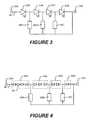
- FIG. 2is a schematic circuit diagram illustrating series interconnection of light emitting devices (LEDs) in a solid state lighting apparatus.
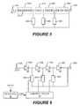
- FIGS. 3-6are schematic circuit diagrams illustrating the electrical interconnection of LEDs in a solid state lighting apparatus in accordance with various embodiments of the invention.
- FIGS. 7A and 7Bare schematic circuit diagrams illustrating the electrical interconnection of LEDs in a solid state lighting apparatus in accordance with various embodiments of the invention.
- FIG. 8is a graph of light intensity versus junction temperature for LEDs having emission wavelengths of 460 nm and 527 nm.
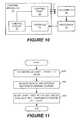
- FIG. 9is a schematic circuit diagram illustrating the electrical interconnection of LEDs in a solid state lighting apparatus in accordance with further embodiments of the invention.
- FIG. 10illustrates systems/methods used to configure the color point of a solid state lighting apparatus according to some embodiments.
- FIG. 11is a flowchart illustrating operations of configuring the color point of a solid state lighting apparatus according to some embodiments of the invention.
- FIGS. 12-15are schematic circuit diagrams illustrating the electrical interconnection of LEDs in solid state lighting apparatus in accordance with further embodiments of the invention.
- Relative terms such as “below” or “above” or “upper” or “lower” or “horizontal” or “vertical”may be used herein to describe a relationship of one element, layer or region to another element, layer or region as illustrated in the figures. It will be understood that these terms are intended to encompass different orientations of the device in addition to the orientation depicted in the figures.
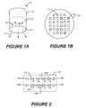
- a lighting apparatus 10according to some embodiments is illustrated.
- the lighting apparatus 10 shown in FIGS. 1A and 1Bis a “can” lighting fixture that may be suitable for use in general illumination applications as a down light or spot light.
- a lighting apparatus according to some embodimentsmay have a different form factor.
- a lighting apparatus according to some embodimentscan have the shape of a conventional light bulb, a pan or tray light, an automotive headlamp, or any other suitable form.
- the lighting apparatus 10generally includes a can shaped outer housing 12 in which a lighting panel 20 is arranged.
- the lighting panel 20has a generally circular shape so as to fit within an interior of the cylindrical housing 12 .
- Lightis generated by solid state lighting devices (LEDs) 22 , 24 , which are mounted on the lighting panel 20 , and which are arranged to emit light 15 towards a diffusing lens 14 mounted at the end of the housing 12 .
- Diffused light 17is emitted through the lens 14 .
- the lens 14may not diffuse the emitted light 15 , but may redirect and/or focus the emitted light 15 in a desired near-field or far-field pattern.
- the solid-state lighting apparatus 10may include a plurality of first LEDs 22 and a plurality of second LEDs 24 .
- the plurality of first LEDs 22may include white emitting, or near white emitting, light emitting devices.
- the plurality of second LEDs 24may include light emitting devices that emit light having a different dominant wavelength from the first LEDs 22 , so that combined light emitted by the first LEDs 22 and the second LEDs 24 may have a desired color and/or spectral content.
- the combined light emitted by the plurality of first LEDs 22 and the plurality of second LEDs 24may be warm white light that has a high color rendering Index.
- the chromaticity of a particular light sourcemay be referred to as the “color point” of the source.
- the chromaticitymay be referred to as the “white point” of the source.
- the white point of a white light sourcemay fall along a locus of chromaticity points corresponding to the color of light emitted by a black-body radiator heated to a given temperature. Accordingly, a white point may be identified by a correlated color temperature (CCT) of the light source, which is the temperature at which the heated black-body radiator matches the hue of the light source.
- CCTcorrelated color temperature
- White lighttypically has a CCT of between about 2500K and 8000K.
- White light with a CCT of 2500Khas a reddish color
- white light with a CCT of 4000Khas a yellowish color
- light with a CCT of 8000Kis bluish in color.
- Warm whitegenerally refers to white light that has a CCT between about 3000 and 3500° K.
- warm white lightmay have wavelength components in the red region of the spectrum, and may appear yellowish to an observer.
- Warm white lighttypically provides a relatively high CRI, and accordingly can cause illuminated objects to have a more natural color. For illumination applications, it is therefore desirable to provide a warm white light.
- Luminous efficacyis a measure of the proportion of the energy supplied to a lamp that is converted into light energy. It is calculated by dividing the lamp's luminous flux, measured in lumens, by the power consumption, measured in watts.
- a lighting devicemay include first and second groups of solid state light emitters, which emit light having dominant wavelength in ranges of from 430 nm to 480 nm and from 600 nm to 630 nm, respectively, and a first group of phosphors which emit light having dominant wavelength in the range of from 555 nm to 585 nm.
- a combination of light exiting the lighting device which was emitted by the first group of emitters, and light exiting the lighting device which was emitted by the first group of phosphorsproduces a sub-mixture of light having x, y color coordinates within a defined area on a 1931 CIE Chromaticity Diagram that is referred to herein as “blue-shifted yellow” or “BSY.”
- BSYBlu-shifted yellow
- Such non-white lightmay, when combined with light having a dominant wavelength from 600 nm to 630 nm, produce warm white light.
- Blue and/or green LEDs used in a lighting apparatusmay be InGaN-based blue and/or green LED chips available from Cree, Inc., the assignee of the present invention.
- Red LEDs used in the lighting apparatusmay be, for example, AlInGaP LED chips available from Epistar, Osram and others.
- the LEDs 22 , 24may have a square or rectangular periphery with an edge length of about 900 ⁇ m or greater (i.e. so-called “power chips.” However, in other embodiments, the LED chips 22 , 24 may have an edge length of 500 ⁇ m or less (i.e. so-called “small chips”). In particular, small LED chips may operate with better electrical conversion efficiency than power chips.
- green LED chips with a maximum edge dimension less than 500 microns and as small as 260 micronscommonly have a higher electrical conversion efficiency than 900 micron chips, and are known to typically produce 55 lumens of luminous flux per Watt of dissipated electrical power and as much as 90 lumens of luminous flux per Watt of dissipated electrical power.
- the LEDs 22 in the lighting apparatus 10may include white/BSY emitting LEDs, while the LEDs 24 in the lighting apparatus may emit red light.
- the LEDs 22 , 24 in the lighting apparatus 10may be electrically interconnected in respective strings, as illustrated in the schematic circuit diagram in FIG. 2 . As shown therein, the LEDs 22 , 24 may be interconnected such that the white/BSY LEDs 22 are connected in series to form a first string 34 A. Likewise, the red LEDs 24 may be arranged in series to form a second string 34 B.
- Each string 32 , 34may be connected to a respective anode terminal 23 A, 25 A and a cathode terminal 23 B, 25 B.
- the lighting apparatus 10may include more or fewer strings. Furthermore, there may be multiple strings of white/BSY LEDs 22 , and multiple strings of red or other colored LEDs 24 .
- the LED string 34could correspond to either or both of the strings 34 A, 34 B illustrated in FIG. 2 .
- the string 34includes four LEDs 24 A- 24 D connected in series between an anode terminal 25 A and a cathode terminal 25 B.
- the string 34includes four LEDs 24 A- 24 D.
- the string 34may include more or fewer LEDs.
- Each of the solid state LEDs 24 A- 24 Cincludes an anode contact and a cathode contact.
- the anode contact of each of the LEDsis coupled to the cathode contact of an adjacent LED in the string or to the anode terminal 25 A of the string, and the cathode contact of each of the LEDs is coupled to the anode contact of an adjacent LED in the string or to the cathode terminal 25 B of the string.
- a plurality of configurable shunts 46 A- 46 Care coupled between an anode contact of a respective one of the LEDs 24 B- 24 D and the cathode terminal 25 B of the string 34 .
- Each of the configurable shunts 46 A- 46 Cmay electrically bypass, for example by short circuiting, one or more of the solid state light emitting devices when a voltage is applied across the anode and cathode terminals 25 A, 25 B of the string 34 .
- the configurable shunts 46 A- 46 Cmay be configured to be conductive or non-conductive.
- the conduction state of the configurable shunts 46 A- 46 Cmay be electrically and/or manually controllable/settable.
- the configurable shunts 46 A- 46 Cmay include tunable resistors that can be tuned between a high impedance state and a low impedance state.
- the tunable resistorsmay be manually and/or electrically tunable.
- the configurable shunts 46 A- 46 Cmay be settable to a conductive state or a non-conductive state, and may remain in such a state after being set.
- the configurable shunts 46 A- 46 Cmay include fuses, switches, jumpers, etc., that can be set to a conductive or non-conductive state.
- one of the configurable shunts 46 A- 46 Cmay be conductive, so that the string 34 effectively includes fewer LEDs 24 A- 24 D.
- the total luminescent power output by the string 34will thereby be reduced, which means that the color point of mixed light that is a combination of light emitted by the string 34 and another string 32 within the lighting apparatus 10 will be altered.
- the color point of the lighting apparatus 10may thereby be adjusted by configuring the conduction state of the configurable shunts 46 A- 46 C of the string 34 .
- Current through the string 34may be provided by a constant current source, such as the variable voltage boost current source described in U.S. Publication No. 20070115248, assigned to the assignee of the present invention, and the disclosure of which is incorporated herein by reference. Thus, switching one or more of the LEDs 24 A- 24 D out of the string 34 may not affect the current supplied to the string.
- a constant current sourcesuch as the variable voltage boost current source described in U.S. Publication No. 20070115248, assigned to the assignee of the present invention, and the disclosure of which is incorporated herein by reference.
- the solid state light emitting devicesmay be arranged into respective groups 44 A- 44 C of series-connected solid state light emitting devices 24 .
- the groups 44 A- 44 C of series-connected solid state light emitting devicesare connected in series between the anode contact 25 A of the string 34 and the cathode contact 25 B of the string 34 .
- the configurable shunts 46 A- 46 Care coupled to cathode contacts of the last solid state light emitting devices in each of the respective groups 44 A- 44 C and to the cathode terminal 25 B of the string 34 .
- At least two groups 44 A- 44 Cinclude different numbers of solid state light emitting devices 24 .
- group 44 Aincludes four LEDs 24
- group 44 Bincludes three LEDs
- group 44 Cincludes two LEDs.
- group 44 Aincludes four LEDs 24
- group 44 Bincludes one LED
- group 44 Cincludes two LEDs.
- the string 34may effectively include four, seven, nine or ten LEDs depending on the conduction/nonconduction states of the configurable shunts 46 A- 46 C.
- the string 34may effectively include four, five, seven or ten LEDs depending on the conduction/nonconduction states of the configurable shunts 46 A- 46 C.
- the number of LEDs in a group 44 A- 44 C and the arrangement of the configurable shunts 46 A- 46 Caffects the ability of a system or user to configure the number of LEDs that will actually be energized when a voltage is applied to the anode and cathode terminals 25 A, 25 B of the string 34 .
- a configurable shunt 46 A- 46 Cmay include a switch coupled between the anode contact of the one of the solid state light emitting devices 24 A- 24 D and the cathode terminal 25 B of the string.
- the switchmay include an electrically controllable switch 56 A- 56 C
- the solid state lighting apparatusmay further include a control circuit 50 coupled to the switches 56 A- 56 C and configured to electrically control an ON/OFF state of the switches 56 A- 56 C.
- the solid state lighting apparatus 10may further include an interface 52 coupled to the control circuit 50 and configured to receive an external input and responsively provide a switch command CMD to the control circuit 50 .
- the control circuit 50may be configured to control the ON/OFF state of the switches 56 A- 56 C in response to the switch command.
- the external inputmay comprise an electronic and/or manual input.
- the solid state light emitting apparatus 10may further include a thermistor 60 A coupled in series with the LEDs 24 A- 24 D ( FIG. 7A ) and/or a thermistor 60 B coupled in parallel ( FIG. 7B ) with the LEDs 24 A- 24 D in the string 34 .
- the thermistor 60may be used to compensate for changes in light emission characteristics of the LEDs 24 that occur in response to changes in the junction temperature of the LEDs 24 .
- the luminescent output of LEDsmay decrease with increased junction temperature, as illustrated in FIG. 8 , which is a graph of light intensity versus junction temperature for EZ1000 LEDs manufactured by Cree, Inc., Durham, N.C. having emission wavelengths of 460 nm (curve 801 ) and 527 nm (curve 802 ).
- the series connected thermistor 60 Amay have a negative temperature coefficient (i.e., the resistance of the thermistor 60 A decreases with increased temperature) while the parallel connected thermistor 60 B may have a positive temperature coefficient (resistance increases with increased temperature), so that current passing through LEDs 24 may be increased with increasing temperature to compensate for the reduction in light intensity as the temperature of the devices increases.
- the solid state light emitting apparatusmay further include a variable resistor 70 A coupled in series with the string 34 and/or a variable resistor 70 B coupled in parallel with the string 34 .
- the resistances of the variable resistors 70 A, 70 Bcan be dynamically altered to compensate for temperature-induced changes in light emission as described above in connection with the thermistors 60 A, 60 B, and also to compensate for drift in the emission characteristics of the LEDs 24 A- 24 D that can occur over time.
- FIGS. 10 and 11illustrate systems/methods used to calibrate a lighting apparatus 10 according to some embodiments.
- a lighting apparatus 10including a lighting panel 20 , a control circuit 50 and an interface 52 may be calibrated using a colorimeter 72 and a processor 76 .
- Light 17 generated by the lighting panel 20is emitted by the lighting apparatus 10 and detected by the colorimeter 72 .
- the colorimeter 72may be, for example, a PR-650 SpectraScan® Colorimeter from Photo Research Inc., which can be used to make direct measurements of luminance, CIE Chromaticity (1931 xy and 1976 u′v′) and/or correlated color temperature.
- a color point of the light 17may be detected by the colorimeter 72 and communicated to the processor 76 .
- the processor 76may determine that light output of one or more strings of LEDs in the lighting panel 20 should be altered by switching one or more LEDs, or groups of LEDs out of the string using the configurable shunts.
- the processor 76may then issue a command to the control circuit 50 via the interface 52 to set the conductivity of one or more of the configurable shunts, and thereby adjust the color point of the light 17 output by lighting panel 20 .
- FIG. 11is a flowchart illustrating operations according to some embodiments for adjusting the light output of a string of series-connected LEDs 24 A- 24 D, such as the string 34 illustrated in FIG. 3 .
- a reference currentis passed through the string 34 (Block 610 ), and color and/or intensity of light output from the string in response to the reference current is measured (Block 620 ).
- at least one configurable shunt 46 A- 46 Cis provided between an anode contact of one of the LEDs 24 A- 24 D and the cathode terminal of the string 34 (Block 630 ).
- the configurable shunt 46 A- 46 Celectrically bypasses at least one of the LEDs 24 A- 24 D when a voltage is applied across the anode and cathode terminals of the string 34 .
- the configurable shunts 46 A- 46 Cmay be provided between respective cathode contacts of the LEDs 24 A- 24 C and the anode contact 25 A of the string 34 .
- the configurable shunts 46 A- 46 Cmay be provided between respective cathode contacts of groups 44 A- 44 C of LEDs and the anode contact 25 A of the string 34 .
- some of the configurable shuntsmay be provided between anode contacts of some of the LEDs 24 A- 24 D and the cathode contact 25 B of the string 34
- others of the configurable shuntsmay be provided between cathode contacts of some of the LEDs 24 A- 24 D and the anode contact 25 A of the string 34
- the configurable shunts 46 A, 46 Bare connected between the cathodes of the LEDs 24 A, 24 B and the anode contact 25 A of the string 34
- the configurable shunt 46 Cis connected between the anode of the LED 24 D and the cathode contact 25 B of the string 34 .
- a circuit 74includes light emitting devices 24 A, 24 B connected in parallel between anode and cathode contacts 75 A, 75 B.
- a configurable shunt 66is connected in parallel with the light emitting devices 24 A, 24 B.
- the configurable shunt 66may include a switch, fuse, thermistor, variable resistor, etc., as described above.
- the configurable shuntmay be configured and/or controlled to alter current flowing through the parallel light emitting devices 24 A, 24 B.
Landscapes
- Circuit Arrangement For Electric Light Sources In General (AREA)
- Non-Portable Lighting Devices Or Systems Thereof (AREA)
- Led Devices (AREA)
Abstract
Description
Claims (28)
Priority Applications (7)
| Application Number | Priority Date | Filing Date | Title |
|---|---|---|---|
| US12/566,142US8901829B2 (en) | 2009-09-24 | 2009-09-24 | Solid state lighting apparatus with configurable shunts |
| PCT/US2010/048225WO2011037752A2 (en) | 2009-09-24 | 2010-09-09 | Solid state lighting apparatus with configurable shunts |
| JP2012530920AJP5820380B2 (en) | 2009-09-24 | 2010-09-09 | Semiconductor lighting device with configurable shunt |
| EP10819235.2AEP2471346B1 (en) | 2009-09-24 | 2010-09-09 | Solid state lighting apparatus with configurable shunts |
| CN201080053889.XACN103262657B (en) | 2009-09-24 | 2010-09-09 | There is the solid-state lighting device of configurable diverter |
| KR1020127010059AKR20120100929A (en) | 2009-09-24 | 2010-09-09 | Solid state lighting apparatus with configurable shunts |
| TW099131730ATW201130381A (en) | 2009-09-24 | 2010-09-17 | Solid state lighting apparatus with configurable shunts |
Applications Claiming Priority (1)
| Application Number | Priority Date | Filing Date | Title |
|---|---|---|---|
| US12/566,142US8901829B2 (en) | 2009-09-24 | 2009-09-24 | Solid state lighting apparatus with configurable shunts |
Publications (2)
| Publication Number | Publication Date |
|---|---|
| US20110068696A1 US20110068696A1 (en) | 2011-03-24 |
| US8901829B2true US8901829B2 (en) | 2014-12-02 |
Family
ID=43756034
Family Applications (1)
| Application Number | Title | Priority Date | Filing Date |
|---|---|---|---|
| US12/566,142ActiveUS8901829B2 (en) | 2009-09-24 | 2009-09-24 | Solid state lighting apparatus with configurable shunts |
Country Status (7)
| Country | Link |
|---|---|
| US (1) | US8901829B2 (en) |
| EP (1) | EP2471346B1 (en) |
| JP (1) | JP5820380B2 (en) |
| KR (1) | KR20120100929A (en) |
| CN (1) | CN103262657B (en) |
| TW (1) | TW201130381A (en) |
| WO (1) | WO2011037752A2 (en) |
Cited By (4)
| Publication number | Priority date | Publication date | Assignee | Title |
|---|---|---|---|---|
| EP2332522A2 (en) | 1998-03-19 | 2011-06-15 | Bristol-Myers Squibb Company | Biphasic controlled release delivery system for high solubility pharmaceuticals and method |
| US20150312984A1 (en)* | 2012-12-28 | 2015-10-29 | Silicon Works Co., Ltd. | Control circuit of light-emitting diode lighting apparatus |
| US9706611B2 (en) | 2014-05-30 | 2017-07-11 | Cree, Inc. | Solid state lighting apparatuses, circuits, methods, and computer program products providing targeted spectral power distribution output using pulse width modulation control |
| US20170345363A1 (en)* | 2016-05-31 | 2017-11-30 | Anthem Displays, Llc | Systems and methods for providing redundant data and power |
Families Citing this family (62)
| Publication number | Priority date | Publication date | Assignee | Title |
|---|---|---|---|---|
| US9172012B2 (en) | 2007-10-31 | 2015-10-27 | Cree, Inc. | Multi-chip light emitter packages and related methods |
| US9666762B2 (en) | 2007-10-31 | 2017-05-30 | Cree, Inc. | Multi-chip light emitter packages and related methods |
| US9082921B2 (en) | 2007-10-31 | 2015-07-14 | Cree, Inc. | Multi-die LED package |
| DE102008057347A1 (en)* | 2008-11-14 | 2010-05-20 | Osram Opto Semiconductors Gmbh | Optoelectronic device |
| US10264637B2 (en) | 2009-09-24 | 2019-04-16 | Cree, Inc. | Solid state lighting apparatus with compensation bypass circuits and methods of operation thereof |
| US8901845B2 (en) | 2009-09-24 | 2014-12-02 | Cree, Inc. | Temperature responsive control for lighting apparatus including light emitting devices providing different chromaticities and related methods |
| US9713211B2 (en)* | 2009-09-24 | 2017-07-18 | Cree, Inc. | Solid state lighting apparatus with controllable bypass circuits and methods of operation thereof |
| US8602579B2 (en)* | 2009-09-25 | 2013-12-10 | Cree, Inc. | Lighting devices including thermally conductive housings and related structures |
| US8777449B2 (en) | 2009-09-25 | 2014-07-15 | Cree, Inc. | Lighting devices comprising solid state light emitters |
| US9068719B2 (en)* | 2009-09-25 | 2015-06-30 | Cree, Inc. | Light engines for lighting devices |
| US9285103B2 (en)* | 2009-09-25 | 2016-03-15 | Cree, Inc. | Light engines for lighting devices |
| US9175811B2 (en) | 2010-02-12 | 2015-11-03 | Cree, Inc. | Solid state lighting device, and method of assembling the same |
| US8773007B2 (en) | 2010-02-12 | 2014-07-08 | Cree, Inc. | Lighting devices that comprise one or more solid state light emitters |
| US9518715B2 (en)* | 2010-02-12 | 2016-12-13 | Cree, Inc. | Lighting devices that comprise one or more solid state light emitters |
| US8476836B2 (en) | 2010-05-07 | 2013-07-02 | Cree, Inc. | AC driven solid state lighting apparatus with LED string including switched segments |
| TWI508612B (en)* | 2010-07-28 | 2015-11-11 | Epistar Corp | Light-emitting element with temperature compensation |
| US8569974B2 (en) | 2010-11-01 | 2013-10-29 | Cree, Inc. | Systems and methods for controlling solid state lighting devices and lighting apparatus incorporating such systems and/or methods |
| US8564000B2 (en) | 2010-11-22 | 2013-10-22 | Cree, Inc. | Light emitting devices for light emitting diodes (LEDs) |
| US8575639B2 (en) | 2011-02-16 | 2013-11-05 | Cree, Inc. | Light emitting devices for light emitting diodes (LEDs) |
| US8624271B2 (en) | 2010-11-22 | 2014-01-07 | Cree, Inc. | Light emitting devices |
| US9300062B2 (en) | 2010-11-22 | 2016-03-29 | Cree, Inc. | Attachment devices and methods for light emitting devices |
| US9000470B2 (en) | 2010-11-22 | 2015-04-07 | Cree, Inc. | Light emitter devices |
| US10098197B2 (en) | 2011-06-03 | 2018-10-09 | Cree, Inc. | Lighting devices with individually compensating multi-color clusters |
| USD702653S1 (en) | 2011-10-26 | 2014-04-15 | Cree, Inc. | Light emitting device component |
| US8455908B2 (en) | 2011-02-16 | 2013-06-04 | Cree, Inc. | Light emitting devices |
| US10178723B2 (en)* | 2011-06-03 | 2019-01-08 | Cree, Inc. | Systems and methods for controlling solid state lighting devices and lighting apparatus incorporating such systems and/or methods |
| US8950892B2 (en) | 2011-03-17 | 2015-02-10 | Cree, Inc. | Methods for combining light emitting devices in a white light emitting apparatus that mimics incandescent dimming characteristics and solid state lighting apparatus for general illumination that mimic incandescent dimming characteristics |
| US9839083B2 (en) | 2011-06-03 | 2017-12-05 | Cree, Inc. | Solid state lighting apparatus and circuits including LED segments configured for targeted spectral power distribution and methods of operating the same |
| US9337925B2 (en) | 2011-06-27 | 2016-05-10 | Cree, Inc. | Apparatus and methods for optical control of lighting devices |
| US8684569B2 (en) | 2011-07-06 | 2014-04-01 | Cree, Inc. | Lens and trim attachment structure for solid state downlights |
| US8742671B2 (en) | 2011-07-28 | 2014-06-03 | Cree, Inc. | Solid state lighting apparatus and methods using integrated driver circuitry |
| US8669722B2 (en)* | 2011-08-12 | 2014-03-11 | Tsmc Solid State Lighting Ltd. | Color temperature adjustment for LED lamps using switches |
| KR20140097284A (en) | 2011-11-07 | 2014-08-06 | 크리,인코포레이티드 | High voltage array light emitting diode(led) devices, fixtures and methods |
| US8736186B2 (en) | 2011-11-14 | 2014-05-27 | Cree, Inc. | Solid state lighting switches and fixtures providing selectively linked dimming and color control and methods of operating |
| US10043960B2 (en) | 2011-11-15 | 2018-08-07 | Cree, Inc. | Light emitting diode (LED) packages and related methods |
| US8847516B2 (en) | 2011-12-12 | 2014-09-30 | Cree, Inc. | Lighting devices including current shunting responsive to LED nodes and related methods |
| US8823285B2 (en) | 2011-12-12 | 2014-09-02 | Cree, Inc. | Lighting devices including boost converters to control chromaticity and/or brightness and related methods |
| AU2012100032B4 (en)* | 2011-12-22 | 2012-03-08 | Ozuno Holdings Limited | LED lamp with current dependent colour temperature |
| US10187942B2 (en) | 2011-12-23 | 2019-01-22 | Cree, Inc. | Methods and circuits for controlling lighting characteristics of solid state lighting devices and lighting apparatus incorporating such methods and/or circuits |
| TWI562679B (en)* | 2012-01-18 | 2016-12-11 | Polytronics Technology Corp | Current-limiting device and light-emitting diode apparatus containing the same |
| US8803428B2 (en)* | 2012-03-22 | 2014-08-12 | Polytronics Technology Corp. | Current-limiting device and light-emitting diode apparatus containing the same |
| US9735198B2 (en) | 2012-03-30 | 2017-08-15 | Cree, Inc. | Substrate based light emitter devices, components, and related methods |
| US10134961B2 (en) | 2012-03-30 | 2018-11-20 | Cree, Inc. | Submount based surface mount device (SMD) light emitter components and methods |
| USD703624S1 (en) | 2012-04-06 | 2014-04-29 | Cree, Inc. | LED-array package |
| DE102012206889B4 (en)* | 2012-04-26 | 2022-08-25 | Zumtobel Lighting Gmbh | panel light |
| GB2507268A (en)* | 2012-10-23 | 2014-04-30 | Ford Global Tech Llc | Fast heat steering wheel |
| US8896212B2 (en)* | 2013-01-14 | 2014-11-25 | Mp Design Inc. | Thermal control circuit for an active cooling module for a light-emitting diode fixture |
| US10231300B2 (en) | 2013-01-15 | 2019-03-12 | Cree, Inc. | Systems and methods for controlling solid state lighting during dimming and lighting apparatus incorporating such systems and/or methods |
| US10264638B2 (en) | 2013-01-15 | 2019-04-16 | Cree, Inc. | Circuits and methods for controlling solid state lighting |
| US9491825B2 (en)* | 2013-02-05 | 2016-11-08 | Lumens Co., Ltd. | LED lighting device |
| USD740453S1 (en) | 2013-06-27 | 2015-10-06 | Cree, Inc. | Light emitter unit |
| USD739565S1 (en) | 2013-06-27 | 2015-09-22 | Cree, Inc. | Light emitter unit |
| WO2015000863A1 (en)* | 2013-07-02 | 2015-01-08 | Koninklijke Philips N.V. | Led module |
| WO2015085050A1 (en) | 2013-12-06 | 2015-06-11 | Cree, Inc. | Leds configured for targeted spectral power disbution |
| JP2018501628A (en)* | 2015-01-13 | 2018-01-18 | フィリップス ライティング ホールディング ビー ヴィ | Operation of LED lighting elements controlled using light sensitive elements |
| USD823492S1 (en) | 2016-10-04 | 2018-07-17 | Cree, Inc. | Light emitting device |
| DE102018108412A1 (en)* | 2018-04-10 | 2019-10-10 | Siteco Beleuchtungstechnik Gmbh | TEMPERATURE SUPERVISED LED MODULE |
| WO2021001233A1 (en)* | 2019-07-04 | 2021-01-07 | Lumileds Holding B.V. | Lighting device |
| CN111101328B (en)* | 2020-01-10 | 2025-02-07 | 深圳一目科技有限公司 | A spectrum sensor monitoring device and method and intelligent laundry method |
| US11503684B2 (en)* | 2020-07-24 | 2022-11-15 | Ledvance Llc | Light emitting diode luminaires with temperature feedback |
| WO2023004047A1 (en) | 2021-07-21 | 2023-01-26 | Lumileds Llc | Late configurable led module and vehicle headlight |
| CN118872381A (en)* | 2021-12-14 | 2024-10-29 | 亮锐有限责任公司 | System and method for light emitting diode (LED) fault detection |
Citations (135)
| Publication number | Priority date | Publication date | Assignee | Title |
|---|---|---|---|---|
| US4504776A (en) | 1980-11-12 | 1985-03-12 | Bei Electronics, Inc. | Power saving regulated light emitting diode circuit |
| US4798983A (en) | 1986-09-26 | 1989-01-17 | Mitsubishi Denki Kabushiki Kaisha | Driving circuit for cascode BiMOS switch |
| US4839535A (en) | 1988-02-22 | 1989-06-13 | Motorola, Inc. | MOS bandgap voltage reference circuit |
| US5059890A (en) | 1988-12-09 | 1991-10-22 | Fujitsu Limited | Constant current source circuit |
| US5397938A (en) | 1992-10-28 | 1995-03-14 | Siemens Aktiengesellschaft | Current mode logic switching stage |
| US5504448A (en) | 1994-08-01 | 1996-04-02 | Motorola, Inc. | Current limit sense circuit and method for controlling a transistor |
| US5528467A (en) | 1995-09-25 | 1996-06-18 | Wang Chi Industrial Co., Ltd. | Head light structure of a car |
| US5598068A (en) | 1994-03-18 | 1997-01-28 | Sony/Tektronix Corporation | Light emitting apparatus comprising multiple groups of LEDs each containing multiple LEDs |
| USD384430S (en) | 1996-08-07 | 1997-09-30 | Michel Lecluze | light projector |
| US5803579A (en) | 1996-06-13 | 1998-09-08 | Gentex Corporation | Illuminator assembly incorporating light emitting diodes |
| USD400280S (en) | 1997-10-03 | 1998-10-27 | Leen Monte A | Mercury vapor light |
| USD418620S (en) | 1998-09-09 | 2000-01-04 | Regent Lighting Corporation | Outdoor light |
| USD425024S (en) | 1998-09-10 | 2000-05-16 | Dal Partnership | Compact fluorescent bulb socket |
| US6079852A (en) | 1996-12-17 | 2000-06-27 | Piaa Corporation | Auxiliary light |
| US6153980A (en)* | 1999-11-04 | 2000-11-28 | Philips Electronics North America Corporation | LED array having an active shunt arrangement |
| USD437439S1 (en) | 1999-04-30 | 2001-02-06 | Shih-Chuan Tang | Floodlight |
| US6201353B1 (en) | 1999-11-01 | 2001-03-13 | Philips Electronics North America Corporation | LED array employing a lattice relationship |
| US6264354B1 (en) | 2000-07-21 | 2001-07-24 | Kamal Motilal | Supplemental automotive lighting |
| US6323597B1 (en)* | 2000-05-15 | 2001-11-27 | Jlj, Inc. | Thermistor shunt for series wired light string |
| US6329764B1 (en) | 2000-04-19 | 2001-12-11 | Van De Ven Antony | Method and apparatus to improve the color rendering of a solid state light source |
| US20020097095A1 (en) | 2001-01-19 | 2002-07-25 | Samsung Electronics Co., Ltd. | Temperature compensation circuit for a power amplifier |
| US6556067B2 (en) | 2000-06-13 | 2003-04-29 | Linfinity Microelectronics | Charge pump regulator with load current control |
| US6630801B2 (en) | 2001-10-22 | 2003-10-07 | Lümileds USA | Method and apparatus for sensing the color point of an RGB LED white luminary using photodiodes |
| US20040036418A1 (en) | 2002-08-21 | 2004-02-26 | Rooke Alan Michael | Closed loop current control circuit and method thereof |
| US6755550B1 (en) | 2003-02-06 | 2004-06-29 | Amy Lackey | Recessed illuminated tile light |
| US6784622B2 (en) | 2001-12-05 | 2004-08-31 | Lutron Electronics Company, Inc. | Single switch electronic dimming ballast |
| US6791840B2 (en) | 2003-01-17 | 2004-09-14 | James K. Chun | Incandescent tube bulb replacement assembly |
| US20040233145A1 (en) | 2003-05-19 | 2004-11-25 | Add Microtech Corp. | LED driving device |
| US20050007164A1 (en) | 2003-03-28 | 2005-01-13 | Callahan Michael J. | Driver circuit having a slew rate control system with improved linear ramp generator including ground |
| US20050057179A1 (en) | 2003-08-27 | 2005-03-17 | Osram Sylvania Inc. | Driver circuit for LED vehicle lamp |
| US20050111222A1 (en) | 2003-11-21 | 2005-05-26 | Olsson Mark S. | Thru-hull light |
| US20050128752A1 (en) | 2002-04-20 | 2005-06-16 | Ewington Christopher D. | Lighting module |
| US20050169015A1 (en) | 2003-09-18 | 2005-08-04 | Luk John F. | LED color changing luminaire and track light system |
| US20050174065A1 (en)* | 1995-06-26 | 2005-08-11 | Jij, Inc. | LED light strings |
| US20050242742A1 (en)* | 2004-04-30 | 2005-11-03 | Cheang Tak M | Light emitting diode based light system with a redundant light source |
| JP2005310997A (en) | 2004-04-20 | 2005-11-04 | Sony Corp | LED driving device, backlight light source device, and color liquid crystal display device |
| EP1594348A2 (en) | 2004-04-22 | 2005-11-09 | Nec Corporation | Light source controlling circuit and portable electronic apparatus |
| US20050254234A1 (en)* | 2004-05-17 | 2005-11-17 | Kuo-Tsai Wang | LED flashlight |
| US7014341B2 (en) | 2003-10-02 | 2006-03-21 | Acuity Brands, Inc. | Decorative luminaires |
| US20060060882A1 (en)* | 2004-09-22 | 2006-03-23 | Sharp Kabushiki Kaisha | Optical semiconductor device, optical communication device, and electronic equipment |
| JP2006103404A (en) | 2004-10-01 | 2006-04-20 | Koito Mfg Co Ltd | Lighting control circuit for vehicular lamp |
| US20060153511A1 (en)* | 2002-09-18 | 2006-07-13 | Franklin James B | Light emitting device |
| US7081722B1 (en) | 2005-02-04 | 2006-07-25 | Kimlong Huynh | Light emitting diode multiphase driver circuit and method |
| US7088059B2 (en) | 2004-07-21 | 2006-08-08 | Boca Flasher | Modulated control circuit and method for current-limited dimming and color mixing of display and illumination systems |
| US7108238B2 (en) | 1999-05-26 | 2006-09-19 | Regent Lighting Corporation | Outdoor light mounting bracket |
| US20060244396A1 (en) | 2005-04-29 | 2006-11-02 | Constantin Bucur | Serial powering of an LED string |
| US7144140B2 (en) | 2005-02-25 | 2006-12-05 | Tsung-Ting Sun | Heat dissipating apparatus for lighting utility |
| JP2006332022A (en) | 2005-04-26 | 2006-12-07 | Sanyo Epson Imaging Devices Corp | LED drive circuit, illumination device, and electro-optical device |
| US20070018594A1 (en)* | 2005-06-08 | 2007-01-25 | Jlj. Inc. | Holiday light string devices |
| TW200705714A (en) | 2005-04-04 | 2007-02-01 | Cree Inc | Semiconductor light emitting circuits including light emitting diodes and four layer semiconductor shunt devices |
| WO2007023454A1 (en) | 2005-08-26 | 2007-03-01 | Koninklijke Philips Electronics N.V. | Led light source for backlighting with integrated electronics |
| US20070096661A1 (en) | 2005-10-28 | 2007-05-03 | David Allen | Decorative lighting string with stacked rectification |
| US7213940B1 (en) | 2005-12-21 | 2007-05-08 | Led Lighting Fixtures, Inc. | Lighting device and lighting method |
| US20070108843A1 (en) | 2005-11-17 | 2007-05-17 | Preston Nigel A | Series connected power supply for semiconductor-based vehicle lighting systems |
| US7226189B2 (en) | 2005-04-15 | 2007-06-05 | Taiwan Oasis Technology Co., Ltd. | Light emitting diode illumination apparatus |
| US20070195023A1 (en) | 2006-02-22 | 2007-08-23 | Samsung Electronics Co., Ltd. | Light emitting apparatus and control method thereof |
| US20070257623A1 (en) | 2006-03-27 | 2007-11-08 | Texas Instruments, Incorporated | Highly efficient series string led driver with individual led control |
| US20070278974A1 (en) | 2006-05-31 | 2007-12-06 | Led Lighting Fixtures, Inc. | Lighting device with color control, and method of lighting |
| US7307391B2 (en) | 2006-02-09 | 2007-12-11 | Led Smart Inc. | LED lighting system |
| USD557853S1 (en) | 2007-02-10 | 2007-12-18 | Eml Technologies Llc | Yard light with dark sky shade |
| USD558374S1 (en) | 2007-02-10 | 2007-12-25 | Eml Technologies Llc | Yard light |
| US20080024071A1 (en) | 2006-07-31 | 2008-01-31 | Jingjing Yu | Bypass components in series wired led light strings |
| CN101137261A (en) | 2006-08-29 | 2008-03-05 | 安华高科技Ecbuip(新加坡)私人有限公司 | Device and method for driving LED |
| US20080084701A1 (en) | 2006-09-21 | 2008-04-10 | Led Lighting Fixtures, Inc. | Lighting assemblies, methods of installing same, and methods of replacing lights |
| US20080089071A1 (en) | 2006-10-12 | 2008-04-17 | Chin-Wen Wang | Lamp structure with adjustable projection angle |
| WO2008051957A2 (en) | 2006-10-23 | 2008-05-02 | Cree Led Lighting Solutions, Inc. | Lighting devices and methods of installing light engine housings and/or trim elements in lighting device housings |
| JP2008125339A (en) | 2006-10-17 | 2008-05-29 | Kanazawa Inst Of Technology | Inrush current prevention circuit, load drive circuit, and light emitting device using them |
| US20080122376A1 (en) | 2006-11-10 | 2008-05-29 | Philips Solid-State Lighting Solutions | Methods and apparatus for controlling series-connected leds |
| US20080150440A1 (en) | 2006-12-22 | 2008-06-26 | Gemmy Industries Corporation | LED light string with guaranteed conduction |
| US20080157688A1 (en)* | 2006-10-02 | 2008-07-03 | Gibboney James W | Light String of LEDS |
| US7408308B2 (en) | 2005-05-13 | 2008-08-05 | Sharp Kabushiki Kaisha | LED drive circuit, LED lighting device, and backlight |
| US20080186704A1 (en) | 2006-08-11 | 2008-08-07 | Enertron, Inc. | LED Light in Sealed Fixture with Heat Transfer Agent |
| US20080203946A1 (en) | 2007-02-22 | 2008-08-28 | Koito Manufacturing Co., Ltd. | Light emitting apparatus |
| US20080211415A1 (en) | 2006-12-22 | 2008-09-04 | Altamura Steven J | Resistive bypass for series lighting circuit |
| USD576964S1 (en) | 2007-11-08 | 2008-09-16 | Abl Ip Holding, Llc | Heat sink |
| WO2008129504A1 (en) | 2007-04-24 | 2008-10-30 | Philips Intellectual Property & Standards Gmbh | Led string driver with shift register and level shifter |
| US7458706B1 (en) | 2007-11-28 | 2008-12-02 | Fu Zhun Precision Industry (Shen Zhen) Co., Ltd. | LED lamp with a heat sink |
| JP2008544569A (en) | 2005-06-28 | 2008-12-04 | ソウル オプト デバイス カンパニー リミテッド | Light-emitting element for alternating current |
| US20080309255A1 (en) | 2007-05-08 | 2008-12-18 | Cree Led Lighting Solutions, Inc | Lighting devices and methods for lighting |
| US20090015759A1 (en) | 2007-07-06 | 2009-01-15 | Nec Lcd Technologies, Ltd | Light emission control circuit, light emission control method, flat illuminating device, and liquid crystal display device having the same device |
| US20090034283A1 (en) | 2007-08-01 | 2009-02-05 | Albright Kim M | Direct view LED lamp with snap fit housing |
| US20090039791A1 (en) | 2007-07-02 | 2009-02-12 | Steve Jones | Entryway lighting system |
| US20090046464A1 (en) | 2007-08-15 | 2009-02-19 | Fu Zhun Precision Industry (Shen Zhen) Co., Ltd. | Led lamp with a heat sink |
| US20090086474A1 (en) | 2007-09-27 | 2009-04-02 | Enertron, Inc. | Method and Apparatus for Thermally Effective Trim for Light Fixture |
| US7513639B2 (en) | 2006-09-29 | 2009-04-07 | Pyroswift Holding Co., Limited | LED illumination apparatus |
| US20090140630A1 (en) | 2005-03-18 | 2009-06-04 | Mitsubishi Chemical Corporation | Light-emitting device, white light-emitting device, illuminator, and image display |
| US20090147517A1 (en) | 2007-12-07 | 2009-06-11 | Fu Zhun Precision Industry (Shen Zhen) Co., Ltd. | Led recessed lamp with screws fixing a recessed fixture thereof |
| US20090160363A1 (en) | 2007-11-28 | 2009-06-25 | Cree Led Lighting Solutions, Inc. | Solid state lighting devices and methods of manufacturing the same |
| US7566154B2 (en) | 2006-09-25 | 2009-07-28 | B/E Aerospace, Inc. | Aircraft LED dome light having rotatably releasable housing mounted within mounting flange |
| US20090195168A1 (en) | 2008-02-05 | 2009-08-06 | Intersil Americas Inc. | Method and system for dimming ac-powered light emitting diode (led) lighting systems using conventional incandescent dimmers |
| US7614767B2 (en) | 2006-06-09 | 2009-11-10 | Abl Ip Holding Llc | Networked architectural lighting with customizable color accents |
| US7614769B2 (en) | 2007-11-23 | 2009-11-10 | Sell Timothy L | LED conversion system for recessed lighting |
| US7628513B2 (en) | 2006-11-28 | 2009-12-08 | Primo Lite Co., Ltd. | Led lamp structure |
| US7637635B2 (en) | 2007-11-21 | 2009-12-29 | Fu Zhun Precision Industry (Shen Zhen) Co., Ltd. | LED lamp with a heat sink |
| US7656371B2 (en) | 2003-07-28 | 2010-02-02 | Nichia Corporation | Light emitting apparatus, LED lighting, LED light emitting apparatus, and control method of light emitting apparatus |
| USD610291S1 (en) | 2008-05-26 | 2010-02-16 | Toshiba Lighting & Technology Corporation | Recessed lighting fixture |
| US20100060175A1 (en)* | 2008-09-09 | 2010-03-11 | Exclara Inc. | Apparatus, Method and System for Providing Power to Solid State Lighting |
| US7677767B2 (en) | 2008-04-01 | 2010-03-16 | Wen-Long Chyn | LED lamp having higher efficiency |
| US20100072902A1 (en) | 2006-10-06 | 2010-03-25 | Koninklijke Philips Electronics N.V. | Light element array with controllable current sources and method of operation |
| US20100079262A1 (en) | 2008-09-26 | 2010-04-01 | Albeo Technologies, Inc. | Systems And Methods For Conveying Information Using A Control Signal Referenced To Alternating Current (AC) Power |
| US20100090604A1 (en) | 2008-10-09 | 2010-04-15 | Yasuhiro Maruyama | Led drive circuit, led illumination component, led illumination device, and led illumination system |
| US20100109570A1 (en) | 2008-11-06 | 2010-05-06 | Mpj Lighting, Llc | Electrical circuit for driving leds in dissimilar color string lengths |
| US20100123403A1 (en) | 2008-11-17 | 2010-05-20 | Reed William G | Electronic control to regulate power for solid-state lighting and methods thereof |
| US20100134018A1 (en) | 2008-11-30 | 2010-06-03 | Microsemi Corp. - Analog Mixed Signal Group Ltd. | Led string driver with light intensity responsive to input voltage |
| USD618376S1 (en) | 2004-02-19 | 2010-06-22 | Zumtobel Staff Gmbh & Co. Kg | Lighting fixture |
| US7758223B2 (en) | 2005-04-08 | 2010-07-20 | Toshiba Lighting & Technology Corporation | Lamp having outer shell to radiate heat of light source |
| US20100194274A1 (en) | 2007-07-23 | 2010-08-05 | Nxp B.V. | Light emitting diode (led) arrangement with bypass driving |
| US7780318B2 (en) | 2008-02-01 | 2010-08-24 | Fu Zhun Precision Industry (Shen Zhen) Co., Ltd. | Flood lamp assembly having a reinforced bracket for supporting a weight thereof |
| US20100246197A1 (en) | 2007-11-07 | 2010-09-30 | Sharp Kabushiki Kaisha | Illumination device and image display device |
| USD625038S1 (en) | 2008-07-25 | 2010-10-05 | Fawoo Technology Co., Ltd. | Explosion-resistant street light |
| US7824075B2 (en) | 2006-06-08 | 2010-11-02 | Lighting Science Group Corporation | Method and apparatus for cooling a lightbulb |
| USD627502S1 (en) | 2009-11-06 | 2010-11-16 | Foxconn Technology Co., Ltd. | LED lamp |
| USD627911S1 (en) | 2009-12-07 | 2010-11-23 | Foxconn Technology Co., Ltd. | LED lamp |
| US20100308739A1 (en)* | 2009-06-04 | 2010-12-09 | Exclara Inc. | Apparatus, Method and System for Providing AC Line Power to Lighting Devices |
| US20100308738A1 (en) | 2009-06-04 | 2010-12-09 | Exclara Inc. | Apparatus, Method and System for Providing AC Line Power to Lighting Devices |
| US20100327746A1 (en) | 2009-06-30 | 2010-12-30 | Toshiba Lighting & Technology Corporation | Lamp and lighting equipment using the same |
| US7862201B2 (en) | 2005-07-20 | 2011-01-04 | Tbt Asset Management International Limited | Fluorescent lamp for lighting applications |
| US7871184B2 (en) | 2007-11-28 | 2011-01-18 | Cooler Master Co., Ltd | Heat dissipating structure and lamp having the same |
| US20110025217A1 (en) | 2009-08-03 | 2011-02-03 | Intersil Americas Inc. | Inrush current limiter for an led driver |
| US7914902B2 (en) | 2007-11-06 | 2011-03-29 | Jiing Tung Tec. Metal Co., Ltd. | Thermal module |
| US20110075414A1 (en) | 2009-09-25 | 2011-03-31 | Cree Led Lighting Solutions, Inc. | Light engines for lighting devices |
| US20110074265A1 (en) | 2009-09-25 | 2011-03-31 | Cree Led Lighting Solutions, Inc. | Lighting device with one or more removable heat sink elements |
| US20110075411A1 (en) | 2009-09-25 | 2011-03-31 | Cree Led Lighting Solutions, Inc. | Light engines for lighting devices |
| USD636922S1 (en) | 2009-08-25 | 2011-04-26 | Toshiba Lighting & Technology Corporation | Recessed lighting fixture |
| US20110109228A1 (en) | 2009-11-06 | 2011-05-12 | Tsutomu Shimomura | System and method for lighting power and control system |
| US20110169417A1 (en) | 2009-07-17 | 2011-07-14 | Bridgelux, Inc. | Reconfigurable LED Array and Use in Lighting System |
| US20110180818A1 (en) | 2010-08-27 | 2011-07-28 | Quarkstar, Llc | Solid State Light Sheet Using Thin LEDs For General Illumination |
| US7994725B2 (en) | 2008-11-06 | 2011-08-09 | Osram Sylvania Inc. | Floating switch controlling LED array segment |
| USD646011S1 (en) | 2010-07-27 | 2011-09-27 | Hamid Rashidi | LED light with baffle trim |
| US8157422B2 (en) | 2010-06-24 | 2012-04-17 | Lg Electronics Inc. | Lighting apparatus |
| US20120176826A1 (en) | 2011-01-11 | 2012-07-12 | Braxton Engineering, Inc. | Source and multiple loads regulator |
| US20120194073A1 (en) | 2011-01-28 | 2012-08-02 | Jing-Chyi Wang | Driving circuit capable of enhancing energy conversion efficiency and driving method thereof |
| US8235555B2 (en) | 2007-06-13 | 2012-08-07 | Electraled, Inc. | Multiple use LED light fixture |
| US8246202B2 (en) | 2008-02-13 | 2012-08-21 | Mart Gary K | Light emitting diode bulb |
| US20130278157A1 (en) | 2010-12-21 | 2013-10-24 | Koninklijke Philips Electronics N.V. | Device and method for controlling current to solid state lighting circuit |
Family Cites Families (4)
| Publication number | Priority date | Publication date | Assignee | Title |
|---|---|---|---|---|
| JPS57172586A (en)* | 1981-04-16 | 1982-10-23 | Toshiba Corp | Semiconductor integrated circuit |
| US20080150439A1 (en)* | 2005-04-29 | 2008-06-26 | O2Micro. Inc. | Serial powering of an light emitting diode string |
| CA2641782A1 (en)* | 2006-02-10 | 2007-08-16 | Tir Technology Lp | Light source intensity control system and method |
| US7884558B2 (en)* | 2006-07-14 | 2011-02-08 | Wolfson Microelectronics Plc | Driver apparatus and method |
- 2009
- 2009-09-24USUS12/566,142patent/US8901829B2/enactiveActive
- 2010
- 2010-09-09CNCN201080053889.XApatent/CN103262657B/enactiveActive
- 2010-09-09EPEP10819235.2Apatent/EP2471346B1/enactiveActive
- 2010-09-09KRKR1020127010059Apatent/KR20120100929A/ennot_activeWithdrawn
- 2010-09-09WOPCT/US2010/048225patent/WO2011037752A2/enactiveApplication Filing
- 2010-09-09JPJP2012530920Apatent/JP5820380B2/enactiveActive
- 2010-09-17TWTW099131730Apatent/TW201130381A/enunknown
Patent Citations (145)
| Publication number | Priority date | Publication date | Assignee | Title |
|---|---|---|---|---|
| US4504776A (en) | 1980-11-12 | 1985-03-12 | Bei Electronics, Inc. | Power saving regulated light emitting diode circuit |
| US4798983A (en) | 1986-09-26 | 1989-01-17 | Mitsubishi Denki Kabushiki Kaisha | Driving circuit for cascode BiMOS switch |
| US4839535A (en) | 1988-02-22 | 1989-06-13 | Motorola, Inc. | MOS bandgap voltage reference circuit |
| US5059890A (en) | 1988-12-09 | 1991-10-22 | Fujitsu Limited | Constant current source circuit |
| US5397938A (en) | 1992-10-28 | 1995-03-14 | Siemens Aktiengesellschaft | Current mode logic switching stage |
| US5598068A (en) | 1994-03-18 | 1997-01-28 | Sony/Tektronix Corporation | Light emitting apparatus comprising multiple groups of LEDs each containing multiple LEDs |
| US5504448A (en) | 1994-08-01 | 1996-04-02 | Motorola, Inc. | Current limit sense circuit and method for controlling a transistor |
| US20050174065A1 (en)* | 1995-06-26 | 2005-08-11 | Jij, Inc. | LED light strings |
| US5528467A (en) | 1995-09-25 | 1996-06-18 | Wang Chi Industrial Co., Ltd. | Head light structure of a car |
| US5803579A (en) | 1996-06-13 | 1998-09-08 | Gentex Corporation | Illuminator assembly incorporating light emitting diodes |
| USD384430S (en) | 1996-08-07 | 1997-09-30 | Michel Lecluze | light projector |
| US6079852A (en) | 1996-12-17 | 2000-06-27 | Piaa Corporation | Auxiliary light |
| USD400280S (en) | 1997-10-03 | 1998-10-27 | Leen Monte A | Mercury vapor light |
| USD418620S (en) | 1998-09-09 | 2000-01-04 | Regent Lighting Corporation | Outdoor light |
| USD425024S (en) | 1998-09-10 | 2000-05-16 | Dal Partnership | Compact fluorescent bulb socket |
| USD437439S1 (en) | 1999-04-30 | 2001-02-06 | Shih-Chuan Tang | Floodlight |
| US7108238B2 (en) | 1999-05-26 | 2006-09-19 | Regent Lighting Corporation | Outdoor light mounting bracket |
| US6201353B1 (en) | 1999-11-01 | 2001-03-13 | Philips Electronics North America Corporation | LED array employing a lattice relationship |
| US6153980A (en)* | 1999-11-04 | 2000-11-28 | Philips Electronics North America Corporation | LED array having an active shunt arrangement |
| US6329764B1 (en) | 2000-04-19 | 2001-12-11 | Van De Ven Antony | Method and apparatus to improve the color rendering of a solid state light source |
| US6323597B1 (en)* | 2000-05-15 | 2001-11-27 | Jlj, Inc. | Thermistor shunt for series wired light string |
| US6556067B2 (en) | 2000-06-13 | 2003-04-29 | Linfinity Microelectronics | Charge pump regulator with load current control |
| US6264354B1 (en) | 2000-07-21 | 2001-07-24 | Kamal Motilal | Supplemental automotive lighting |
| US20020097095A1 (en) | 2001-01-19 | 2002-07-25 | Samsung Electronics Co., Ltd. | Temperature compensation circuit for a power amplifier |
| CN1575623A (en) | 2001-10-22 | 2005-02-02 | 皇家飞利浦电子股份有限公司 | LED control apparatus |
| US6630801B2 (en) | 2001-10-22 | 2003-10-07 | Lümileds USA | Method and apparatus for sensing the color point of an RGB LED white luminary using photodiodes |
| US6784622B2 (en) | 2001-12-05 | 2004-08-31 | Lutron Electronics Company, Inc. | Single switch electronic dimming ballast |
| US20050128752A1 (en) | 2002-04-20 | 2005-06-16 | Ewington Christopher D. | Lighting module |
| US20040036418A1 (en) | 2002-08-21 | 2004-02-26 | Rooke Alan Michael | Closed loop current control circuit and method thereof |
| US20060153511A1 (en)* | 2002-09-18 | 2006-07-13 | Franklin James B | Light emitting device |
| US6791840B2 (en) | 2003-01-17 | 2004-09-14 | James K. Chun | Incandescent tube bulb replacement assembly |
| US6755550B1 (en) | 2003-02-06 | 2004-06-29 | Amy Lackey | Recessed illuminated tile light |
| US20050007164A1 (en) | 2003-03-28 | 2005-01-13 | Callahan Michael J. | Driver circuit having a slew rate control system with improved linear ramp generator including ground |
| US20040233145A1 (en) | 2003-05-19 | 2004-11-25 | Add Microtech Corp. | LED driving device |
| US7656371B2 (en) | 2003-07-28 | 2010-02-02 | Nichia Corporation | Light emitting apparatus, LED lighting, LED light emitting apparatus, and control method of light emitting apparatus |
| US20050057179A1 (en) | 2003-08-27 | 2005-03-17 | Osram Sylvania Inc. | Driver circuit for LED vehicle lamp |
| US20050169015A1 (en) | 2003-09-18 | 2005-08-04 | Luk John F. | LED color changing luminaire and track light system |
| US7014341B2 (en) | 2003-10-02 | 2006-03-21 | Acuity Brands, Inc. | Decorative luminaires |
| US20050111222A1 (en) | 2003-11-21 | 2005-05-26 | Olsson Mark S. | Thru-hull light |
| USD618376S1 (en) | 2004-02-19 | 2010-06-22 | Zumtobel Staff Gmbh & Co. Kg | Lighting fixture |
| JP2005310997A (en) | 2004-04-20 | 2005-11-04 | Sony Corp | LED driving device, backlight light source device, and color liquid crystal display device |
| EP1594348A2 (en) | 2004-04-22 | 2005-11-09 | Nec Corporation | Light source controlling circuit and portable electronic apparatus |
| US7427838B2 (en) | 2004-04-22 | 2008-09-23 | Nec Corporation | Light source controlling circuit and portable electronic apparatus |
| US20050242742A1 (en)* | 2004-04-30 | 2005-11-03 | Cheang Tak M | Light emitting diode based light system with a redundant light source |
| US20050254234A1 (en)* | 2004-05-17 | 2005-11-17 | Kuo-Tsai Wang | LED flashlight |
| US7088059B2 (en) | 2004-07-21 | 2006-08-08 | Boca Flasher | Modulated control circuit and method for current-limited dimming and color mixing of display and illumination systems |
| US20060060882A1 (en)* | 2004-09-22 | 2006-03-23 | Sharp Kabushiki Kaisha | Optical semiconductor device, optical communication device, and electronic equipment |
| JP2006103404A (en) | 2004-10-01 | 2006-04-20 | Koito Mfg Co Ltd | Lighting control circuit for vehicular lamp |
| US7081722B1 (en) | 2005-02-04 | 2006-07-25 | Kimlong Huynh | Light emitting diode multiphase driver circuit and method |
| US7144140B2 (en) | 2005-02-25 | 2006-12-05 | Tsung-Ting Sun | Heat dissipating apparatus for lighting utility |
| US20090140630A1 (en) | 2005-03-18 | 2009-06-04 | Mitsubishi Chemical Corporation | Light-emitting device, white light-emitting device, illuminator, and image display |
| US7535180B2 (en) | 2005-04-04 | 2009-05-19 | Cree, Inc. | Semiconductor light emitting circuits including light emitting diodes and four layer semiconductor shunt devices |
| TW200705714A (en) | 2005-04-04 | 2007-02-01 | Cree Inc | Semiconductor light emitting circuits including light emitting diodes and four layer semiconductor shunt devices |
| US7758223B2 (en) | 2005-04-08 | 2010-07-20 | Toshiba Lighting & Technology Corporation | Lamp having outer shell to radiate heat of light source |
| US7226189B2 (en) | 2005-04-15 | 2007-06-05 | Taiwan Oasis Technology Co., Ltd. | Light emitting diode illumination apparatus |
| JP2006332022A (en) | 2005-04-26 | 2006-12-07 | Sanyo Epson Imaging Devices Corp | LED drive circuit, illumination device, and electro-optical device |
| US20060244396A1 (en) | 2005-04-29 | 2006-11-02 | Constantin Bucur | Serial powering of an LED string |
| US7408308B2 (en) | 2005-05-13 | 2008-08-05 | Sharp Kabushiki Kaisha | LED drive circuit, LED lighting device, and backlight |
| US20070018594A1 (en)* | 2005-06-08 | 2007-01-25 | Jlj. Inc. | Holiday light string devices |
| US20100277084A1 (en) | 2005-06-28 | 2010-11-04 | Seoul Opto Device Co., Ltd. | Light emitting device for ac power operation |
| JP2008544569A (en) | 2005-06-28 | 2008-12-04 | ソウル オプト デバイス カンパニー リミテッド | Light-emitting element for alternating current |
| US7862201B2 (en) | 2005-07-20 | 2011-01-04 | Tbt Asset Management International Limited | Fluorescent lamp for lighting applications |
| WO2007023454A1 (en) | 2005-08-26 | 2007-03-01 | Koninklijke Philips Electronics N.V. | Led light source for backlighting with integrated electronics |
| US20070096661A1 (en) | 2005-10-28 | 2007-05-03 | David Allen | Decorative lighting string with stacked rectification |
| US20070108843A1 (en) | 2005-11-17 | 2007-05-17 | Preston Nigel A | Series connected power supply for semiconductor-based vehicle lighting systems |
| US7213940B1 (en) | 2005-12-21 | 2007-05-08 | Led Lighting Fixtures, Inc. | Lighting device and lighting method |
| US7307391B2 (en) | 2006-02-09 | 2007-12-11 | Led Smart Inc. | LED lighting system |
| US20070195023A1 (en) | 2006-02-22 | 2007-08-23 | Samsung Electronics Co., Ltd. | Light emitting apparatus and control method thereof |
| US20070257623A1 (en) | 2006-03-27 | 2007-11-08 | Texas Instruments, Incorporated | Highly efficient series string led driver with individual led control |
| US20070278974A1 (en) | 2006-05-31 | 2007-12-06 | Led Lighting Fixtures, Inc. | Lighting device with color control, and method of lighting |
| US7824075B2 (en) | 2006-06-08 | 2010-11-02 | Lighting Science Group Corporation | Method and apparatus for cooling a lightbulb |
| US7614767B2 (en) | 2006-06-09 | 2009-11-10 | Abl Ip Holding Llc | Networked architectural lighting with customizable color accents |
| US20080024071A1 (en) | 2006-07-31 | 2008-01-31 | Jingjing Yu | Bypass components in series wired led light strings |
| US20080186704A1 (en) | 2006-08-11 | 2008-08-07 | Enertron, Inc. | LED Light in Sealed Fixture with Heat Transfer Agent |
| CN101137261A (en) | 2006-08-29 | 2008-03-05 | 安华高科技Ecbuip(新加坡)私人有限公司 | Device and method for driving LED |
| US20080094000A1 (en) | 2006-08-29 | 2008-04-24 | Kenji Yamamoto | Device and method for driving led |
| US20080084701A1 (en) | 2006-09-21 | 2008-04-10 | Led Lighting Fixtures, Inc. | Lighting assemblies, methods of installing same, and methods of replacing lights |
| US7566154B2 (en) | 2006-09-25 | 2009-07-28 | B/E Aerospace, Inc. | Aircraft LED dome light having rotatably releasable housing mounted within mounting flange |
| US7513639B2 (en) | 2006-09-29 | 2009-04-07 | Pyroswift Holding Co., Limited | LED illumination apparatus |
| US20080157688A1 (en)* | 2006-10-02 | 2008-07-03 | Gibboney James W | Light String of LEDS |
| US20100072902A1 (en) | 2006-10-06 | 2010-03-25 | Koninklijke Philips Electronics N.V. | Light element array with controllable current sources and method of operation |
| US20080089071A1 (en) | 2006-10-12 | 2008-04-17 | Chin-Wen Wang | Lamp structure with adjustable projection angle |
| JP2008125339A (en) | 2006-10-17 | 2008-05-29 | Kanazawa Inst Of Technology | Inrush current prevention circuit, load drive circuit, and light emitting device using them |
| WO2008051957A2 (en) | 2006-10-23 | 2008-05-02 | Cree Led Lighting Solutions, Inc. | Lighting devices and methods of installing light engine housings and/or trim elements in lighting device housings |
| US20080122376A1 (en) | 2006-11-10 | 2008-05-29 | Philips Solid-State Lighting Solutions | Methods and apparatus for controlling series-connected leds |
| US7628513B2 (en) | 2006-11-28 | 2009-12-08 | Primo Lite Co., Ltd. | Led lamp structure |
| US20080150440A1 (en) | 2006-12-22 | 2008-06-26 | Gemmy Industries Corporation | LED light string with guaranteed conduction |
| US20080211415A1 (en) | 2006-12-22 | 2008-09-04 | Altamura Steven J | Resistive bypass for series lighting circuit |
| USD558374S1 (en) | 2007-02-10 | 2007-12-25 | Eml Technologies Llc | Yard light |
| USD557853S1 (en) | 2007-02-10 | 2007-12-18 | Eml Technologies Llc | Yard light with dark sky shade |
| JP2008205357A (en) | 2007-02-22 | 2008-09-04 | Koito Mfg Co Ltd | Light emitting apparatus |
| US20080203946A1 (en) | 2007-02-22 | 2008-08-28 | Koito Manufacturing Co., Ltd. | Light emitting apparatus |
| JP2010527459A (en) | 2007-04-24 | 2010-08-12 | コーニンクレッカ フィリップス エレクトロニクス エヌ ヴィ | LED string driving device having shift register and level shifter |
| WO2008129504A1 (en) | 2007-04-24 | 2008-10-30 | Philips Intellectual Property & Standards Gmbh | Led string driver with shift register and level shifter |
| US20080309255A1 (en) | 2007-05-08 | 2008-12-18 | Cree Led Lighting Solutions, Inc | Lighting devices and methods for lighting |
| US8235555B2 (en) | 2007-06-13 | 2012-08-07 | Electraled, Inc. | Multiple use LED light fixture |
| US20090039791A1 (en) | 2007-07-02 | 2009-02-12 | Steve Jones | Entryway lighting system |
| US20090015759A1 (en) | 2007-07-06 | 2009-01-15 | Nec Lcd Technologies, Ltd | Light emission control circuit, light emission control method, flat illuminating device, and liquid crystal display device having the same device |
| JP2009016280A (en) | 2007-07-06 | 2009-01-22 | Nec Lcd Technologies Ltd | Light emission control circuit, light emission control method, surface illumination device, and liquid crystal display device including the surface illumination device |
| US20100194274A1 (en) | 2007-07-23 | 2010-08-05 | Nxp B.V. | Light emitting diode (led) arrangement with bypass driving |
| US20090034283A1 (en) | 2007-08-01 | 2009-02-05 | Albright Kim M | Direct view LED lamp with snap fit housing |
| US20090046464A1 (en) | 2007-08-15 | 2009-02-19 | Fu Zhun Precision Industry (Shen Zhen) Co., Ltd. | Led lamp with a heat sink |
| US20090086474A1 (en) | 2007-09-27 | 2009-04-02 | Enertron, Inc. | Method and Apparatus for Thermally Effective Trim for Light Fixture |
| US7914902B2 (en) | 2007-11-06 | 2011-03-29 | Jiing Tung Tec. Metal Co., Ltd. | Thermal module |
| US20100246197A1 (en) | 2007-11-07 | 2010-09-30 | Sharp Kabushiki Kaisha | Illumination device and image display device |
| USD576964S1 (en) | 2007-11-08 | 2008-09-16 | Abl Ip Holding, Llc | Heat sink |
| US7637635B2 (en) | 2007-11-21 | 2009-12-29 | Fu Zhun Precision Industry (Shen Zhen) Co., Ltd. | LED lamp with a heat sink |
| US7614769B2 (en) | 2007-11-23 | 2009-11-10 | Sell Timothy L | LED conversion system for recessed lighting |
| US7871184B2 (en) | 2007-11-28 | 2011-01-18 | Cooler Master Co., Ltd | Heat dissipating structure and lamp having the same |
| US20090160363A1 (en) | 2007-11-28 | 2009-06-25 | Cree Led Lighting Solutions, Inc. | Solid state lighting devices and methods of manufacturing the same |
| US7458706B1 (en) | 2007-11-28 | 2008-12-02 | Fu Zhun Precision Industry (Shen Zhen) Co., Ltd. | LED lamp with a heat sink |
| US20090147517A1 (en) | 2007-12-07 | 2009-06-11 | Fu Zhun Precision Industry (Shen Zhen) Co., Ltd. | Led recessed lamp with screws fixing a recessed fixture thereof |
| US7780318B2 (en) | 2008-02-01 | 2010-08-24 | Fu Zhun Precision Industry (Shen Zhen) Co., Ltd. | Flood lamp assembly having a reinforced bracket for supporting a weight thereof |
| US20090195168A1 (en) | 2008-02-05 | 2009-08-06 | Intersil Americas Inc. | Method and system for dimming ac-powered light emitting diode (led) lighting systems using conventional incandescent dimmers |
| US8246202B2 (en) | 2008-02-13 | 2012-08-21 | Mart Gary K | Light emitting diode bulb |
| US7677767B2 (en) | 2008-04-01 | 2010-03-16 | Wen-Long Chyn | LED lamp having higher efficiency |
| USD610291S1 (en) | 2008-05-26 | 2010-02-16 | Toshiba Lighting & Technology Corporation | Recessed lighting fixture |
| USD625038S1 (en) | 2008-07-25 | 2010-10-05 | Fawoo Technology Co., Ltd. | Explosion-resistant street light |
| US20100060175A1 (en)* | 2008-09-09 | 2010-03-11 | Exclara Inc. | Apparatus, Method and System for Providing Power to Solid State Lighting |
| US20100079262A1 (en) | 2008-09-26 | 2010-04-01 | Albeo Technologies, Inc. | Systems And Methods For Conveying Information Using A Control Signal Referenced To Alternating Current (AC) Power |
| US20100090604A1 (en) | 2008-10-09 | 2010-04-15 | Yasuhiro Maruyama | Led drive circuit, led illumination component, led illumination device, and led illumination system |
| JP2010092776A (en) | 2008-10-09 | 2010-04-22 | Sharp Corp | Led driving circuit, led illumination fixture, led illumination equipment, and led illumination system |
| US20100109570A1 (en) | 2008-11-06 | 2010-05-06 | Mpj Lighting, Llc | Electrical circuit for driving leds in dissimilar color string lengths |
| US7994725B2 (en) | 2008-11-06 | 2011-08-09 | Osram Sylvania Inc. | Floating switch controlling LED array segment |
| US20100123403A1 (en) | 2008-11-17 | 2010-05-20 | Reed William G | Electronic control to regulate power for solid-state lighting and methods thereof |
| US20100134018A1 (en) | 2008-11-30 | 2010-06-03 | Microsemi Corp. - Analog Mixed Signal Group Ltd. | Led string driver with light intensity responsive to input voltage |
| US20100308739A1 (en)* | 2009-06-04 | 2010-12-09 | Exclara Inc. | Apparatus, Method and System for Providing AC Line Power to Lighting Devices |
| US20100308738A1 (en) | 2009-06-04 | 2010-12-09 | Exclara Inc. | Apparatus, Method and System for Providing AC Line Power to Lighting Devices |
| US20100327746A1 (en) | 2009-06-30 | 2010-12-30 | Toshiba Lighting & Technology Corporation | Lamp and lighting equipment using the same |
| US20110181194A1 (en) | 2009-07-17 | 2011-07-28 | Bridgelux, Inc. | Reconfigurable LED Array and Use in Lighting System |
| US20110169417A1 (en) | 2009-07-17 | 2011-07-14 | Bridgelux, Inc. | Reconfigurable LED Array and Use in Lighting System |
| US20110025217A1 (en) | 2009-08-03 | 2011-02-03 | Intersil Americas Inc. | Inrush current limiter for an led driver |
| USD636922S1 (en) | 2009-08-25 | 2011-04-26 | Toshiba Lighting & Technology Corporation | Recessed lighting fixture |
| US20110075414A1 (en) | 2009-09-25 | 2011-03-31 | Cree Led Lighting Solutions, Inc. | Light engines for lighting devices |
| US20110075411A1 (en) | 2009-09-25 | 2011-03-31 | Cree Led Lighting Solutions, Inc. | Light engines for lighting devices |
| US20110074265A1 (en) | 2009-09-25 | 2011-03-31 | Cree Led Lighting Solutions, Inc. | Lighting device with one or more removable heat sink elements |
| US20110109228A1 (en) | 2009-11-06 | 2011-05-12 | Tsutomu Shimomura | System and method for lighting power and control system |
| USD627502S1 (en) | 2009-11-06 | 2010-11-16 | Foxconn Technology Co., Ltd. | LED lamp |
| USD627911S1 (en) | 2009-12-07 | 2010-11-23 | Foxconn Technology Co., Ltd. | LED lamp |
| US8157422B2 (en) | 2010-06-24 | 2012-04-17 | Lg Electronics Inc. | Lighting apparatus |
| USD646011S1 (en) | 2010-07-27 | 2011-09-27 | Hamid Rashidi | LED light with baffle trim |
| US20110180818A1 (en) | 2010-08-27 | 2011-07-28 | Quarkstar, Llc | Solid State Light Sheet Using Thin LEDs For General Illumination |
| US20130278157A1 (en) | 2010-12-21 | 2013-10-24 | Koninklijke Philips Electronics N.V. | Device and method for controlling current to solid state lighting circuit |
| US20120176826A1 (en) | 2011-01-11 | 2012-07-12 | Braxton Engineering, Inc. | Source and multiple loads regulator |
| US20120194073A1 (en) | 2011-01-28 | 2012-08-02 | Jing-Chyi Wang | Driving circuit capable of enhancing energy conversion efficiency and driving method thereof |
Non-Patent Citations (16)
| Title |
|---|
| Chinese Office Action issued for Application No. 201080053889.X; Date of Mailing: Apr. 4, 2014; Translation of Office Action and Search Report 16 pages; Non-English Office Action 46 pages. |
| Chinese Office Action issued for Application No. 201180022813.5; Date of Mailing: Feb. 25, 2014; Translation 5 pages; Non-English Office Action 16 pages. |
| European Search Report corresponding to European Application No. 10819249.3; Date of Mailing: Mar. 27, 2014; 8 pages. |
| European Search Report corresponding to European Application No. 11777867.0; Date of Mailing: May 13, 2014; 7 pages. |
| International Preliminary Report Corresponding to International Application No. PCT/US2011/033736; Date of Mailing: Nov. 22, 2012; 8 Pages. |
| International Preliminary Report on Patentability Corresponding to International Application No. PCT/US2010/048225; Date of Mailing: Feb. 27, 2014; 9 Pages. |
| International Preliminary Report on Patentability Corresponding to International Application No. PCT/US2011/038995; Date of Mailing: Dec. 20, 2012; 7 Pages. |
| International Preliminary Report on Patentability Corresponding to International Application No. PCT/US2012/054869; Date of Mailing: Mar. 27, 2014; 8 Pages. |
| International Preliminary Report on Patentability Corresponding to International Application No. PCT/US2012/054888; Date of Mailing: Mar. 27, 2014; 10 Pages. |
| International Search Report Corresponding to International Application No. PCT/US12/54869; Date of Mailing: Nov. 23, 2012; 10 Pages. |
| International Search Report Corresponding to International Application No. PCT/US12/54888; Date of Mailing: Nov. 23, 2012; 12 Pages. |
| International Search Report Corresponding to International Application No. PCT/US2011/033736; Date of Mailing: Jul. 7, 2011; 10 Pages. |
| Japanese Office Action Corresponding to Japanese Patent Application No. 2012-530920; Date Mailed: Jun. 12, 2013; Foreign Text, 3 Pages, English Translation Thereof, 2 Pages. |
| Japanese Office Action Corresponding to Japanese Patent Application No. 2013-509109; Date Mailed: Sep. 17, 2013; Foreign Text, 1 Page, English Translation Thereof, 3 Pages. |
| Japanese Office Action issued for Application No. 2012-530920; Date of Mailing: May 28, 2014; Translation 2 pages; Non-English Office Action 3 pages. |
| Notification of Transmittal of the International Search Report and the Written Opinion of the International Searching Authority, or the Declaration; International Search Report; Written Opinion of the International Searching Authority; Corresponding to International Application No. PCT/US2010/048225; 11 pages. |
Cited By (6)
| Publication number | Priority date | Publication date | Assignee | Title |
|---|---|---|---|---|
| EP2332522A2 (en) | 1998-03-19 | 2011-06-15 | Bristol-Myers Squibb Company | Biphasic controlled release delivery system for high solubility pharmaceuticals and method |
| US20150312984A1 (en)* | 2012-12-28 | 2015-10-29 | Silicon Works Co., Ltd. | Control circuit of light-emitting diode lighting apparatus |
| US9572210B2 (en)* | 2012-12-28 | 2017-02-14 | Silicon Works Co., Ltd. | Control circuit of light-emitting diode lighting apparatus |
| US9706611B2 (en) | 2014-05-30 | 2017-07-11 | Cree, Inc. | Solid state lighting apparatuses, circuits, methods, and computer program products providing targeted spectral power distribution output using pulse width modulation control |
| US20170345363A1 (en)* | 2016-05-31 | 2017-11-30 | Anthem Displays, Llc | Systems and methods for providing redundant data and power |
| US10121407B2 (en)* | 2016-05-31 | 2018-11-06 | Anthem Displays, Llc | Systems and methods for providing redundant data and power |
Also Published As
| Publication number | Publication date |
|---|---|
| WO2011037752A3 (en) | 2014-03-27 |
| US20110068696A1 (en) | 2011-03-24 |
| JP5820380B2 (en) | 2015-11-24 |
| EP2471346A4 (en) | 2017-05-03 |
| TW201130381A (en) | 2011-09-01 |
| EP2471346B1 (en) | 2018-11-28 |
| CN103262657B (en) | 2016-12-28 |
| KR20120100929A (en) | 2012-09-12 |
| JP2013522811A (en) | 2013-06-13 |
| WO2011037752A2 (en) | 2011-03-31 |
| EP2471346A2 (en) | 2012-07-04 |
| CN103262657A (en) | 2013-08-21 |
Similar Documents
| Publication | Publication Date | Title |
|---|---|---|
| US8901829B2 (en) | Solid state lighting apparatus with configurable shunts | |
| US9839083B2 (en) | Solid state lighting apparatus and circuits including LED segments configured for targeted spectral power distribution and methods of operating the same | |
| US8212466B2 (en) | Solid state lighting devices including light mixtures | |
| CN103732986B (en) | Lighting device with independently compensated multi-color clusters | |
| US10057952B2 (en) | Lighting apparatus using a non-linear current sensor and methods of operation thereof | |
| JP5857138B2 (en) | LED lighting unit with color and dimming control | |
| US10231300B2 (en) | Systems and methods for controlling solid state lighting during dimming and lighting apparatus incorporating such systems and/or methods | |
| US10178723B2 (en) | Systems and methods for controlling solid state lighting devices and lighting apparatus incorporating such systems and/or methods | |
| US9713211B2 (en) | Solid state lighting apparatus with controllable bypass circuits and methods of operation thereof | |
| CN102932986B (en) | Color temperature adjustment of LED lamps using switches | |
| US8847516B2 (en) | Lighting devices including current shunting responsive to LED nodes and related methods | |
| US10264638B2 (en) | Circuits and methods for controlling solid state lighting | |
| JP5654328B2 (en) | Light emitting device | |
| US20150173151A1 (en) | Tunable correlated color temperature led-based white light source with mixing chamber and remote phosphor exit window | |
| US20060082333A1 (en) | Illumination device | |
| WO2015085050A1 (en) | Leds configured for targeted spectral power disbution | |
| US20200053852A1 (en) | Light emitting device | |
| US20200128648A1 (en) | Light emitting devices and methods | |
| WO2014165450A1 (en) | Circuits and methods for controlling solid state lighting |
Legal Events
| Date | Code | Title | Description |
|---|---|---|---|
| AS | Assignment | Owner name:CREE, INC., NORTH CAROLINA Free format text:MERGER;ASSIGNOR:CREE LED LIGHTING SOLUTIONS, INC.;REEL/FRAME:024877/0540 Effective date:20100621 Owner name:CREE LED LIGHTING SOLUTIONS, INC., NORTH CAROLINA Free format text:ASSIGNMENT OF ASSIGNORS INTEREST;ASSIGNORS:VAN DE VEN, ANTONY P.;NEGLEY, GERALD H.;SIGNING DATES FROM 20090911 TO 20090922;REEL/FRAME:024877/0506 | |
| STCF | Information on status: patent grant | Free format text:PATENTED CASE | |
| CC | Certificate of correction | ||
| MAFP | Maintenance fee payment | Free format text:PAYMENT OF MAINTENANCE FEE, 4TH YEAR, LARGE ENTITY (ORIGINAL EVENT CODE: M1551) Year of fee payment:4 | |
| AS | Assignment | Owner name:IDEAL INDUSTRIES LIGHTING LLC, ILLINOIS Free format text:ASSIGNMENT OF ASSIGNORS INTEREST;ASSIGNOR:CREE, INC.;REEL/FRAME:049223/0494 Effective date:20190513 | |
| MAFP | Maintenance fee payment | Free format text:PAYMENT OF MAINTENANCE FEE, 8TH YEAR, LARGE ENTITY (ORIGINAL EVENT CODE: M1552); ENTITY STATUS OF PATENT OWNER: LARGE ENTITY Year of fee payment:8 | |
| AS | Assignment | Owner name:FGI WORLDWIDE LLC, NEW YORK Free format text:SECURITY INTEREST;ASSIGNOR:IDEAL INDUSTRIES LIGHTING LLC;REEL/FRAME:064897/0413 Effective date:20230908 |