US8900277B2 - Bone plate system - Google Patents
Bone plate systemDownload PDFInfo
- Publication number
- US8900277B2 US8900277B2US13/069,354US201113069354AUS8900277B2US 8900277 B2US8900277 B2US 8900277B2US 201113069354 AUS201113069354 AUS 201113069354AUS 8900277 B2US8900277 B2US 8900277B2
- Authority
- US
- United States
- Prior art keywords
- throughbore
- bone plate
- portions
- bone
- retainer
- Prior art date
- Legal status (The legal status is an assumption and is not a legal conclusion. Google has not performed a legal analysis and makes no representation as to the accuracy of the status listed.)
- Expired - Lifetime, expires
Links
Images


Classifications
- A—HUMAN NECESSITIES
- A61—MEDICAL OR VETERINARY SCIENCE; HYGIENE
- A61B—DIAGNOSIS; SURGERY; IDENTIFICATION
- A61B17/00—Surgical instruments, devices or methods
- A61B17/56—Surgical instruments or methods for treatment of bones or joints; Devices specially adapted therefor
- A61B17/58—Surgical instruments or methods for treatment of bones or joints; Devices specially adapted therefor for osteosynthesis, e.g. bone plates, screws or setting implements
- A61B17/68—Internal fixation devices, including fasteners and spinal fixators, even if a part thereof projects from the skin
- A61B17/80—Cortical plates, i.e. bone plates; Instruments for holding or positioning cortical plates, or for compressing bones attached to cortical plates
- A61B17/8033—Cortical plates, i.e. bone plates; Instruments for holding or positioning cortical plates, or for compressing bones attached to cortical plates having indirect contact with screw heads, or having contact with screw heads maintained with the aid of additional components, e.g. nuts, wedges or head covers
- A61B17/8042—Cortical plates, i.e. bone plates; Instruments for holding or positioning cortical plates, or for compressing bones attached to cortical plates having indirect contact with screw heads, or having contact with screw heads maintained with the aid of additional components, e.g. nuts, wedges or head covers the additional component being a cover over the screw head
- A—HUMAN NECESSITIES
- A61—MEDICAL OR VETERINARY SCIENCE; HYGIENE
- A61B—DIAGNOSIS; SURGERY; IDENTIFICATION
- A61B17/00—Surgical instruments, devices or methods
- A61B17/56—Surgical instruments or methods for treatment of bones or joints; Devices specially adapted therefor
- A61B17/58—Surgical instruments or methods for treatment of bones or joints; Devices specially adapted therefor for osteosynthesis, e.g. bone plates, screws or setting implements
- A61B17/68—Internal fixation devices, including fasteners and spinal fixators, even if a part thereof projects from the skin
- A61B17/70—Spinal positioners or stabilisers, e.g. stabilisers comprising fluid filler in an implant
- A61B17/7059—Cortical plates
- A—HUMAN NECESSITIES
- A61—MEDICAL OR VETERINARY SCIENCE; HYGIENE
- A61B—DIAGNOSIS; SURGERY; IDENTIFICATION
- A61B17/00—Surgical instruments, devices or methods
- A61B17/56—Surgical instruments or methods for treatment of bones or joints; Devices specially adapted therefor
- A61B17/58—Surgical instruments or methods for treatment of bones or joints; Devices specially adapted therefor for osteosynthesis, e.g. bone plates, screws or setting implements
- A61B17/68—Internal fixation devices, including fasteners and spinal fixators, even if a part thereof projects from the skin
- A61B17/80—Cortical plates, i.e. bone plates; Instruments for holding or positioning cortical plates, or for compressing bones attached to cortical plates
- A61B17/8033—Cortical plates, i.e. bone plates; Instruments for holding or positioning cortical plates, or for compressing bones attached to cortical plates having indirect contact with screw heads, or having contact with screw heads maintained with the aid of additional components, e.g. nuts, wedges or head covers
- A61B17/8047—Cortical plates, i.e. bone plates; Instruments for holding or positioning cortical plates, or for compressing bones attached to cortical plates having indirect contact with screw heads, or having contact with screw heads maintained with the aid of additional components, e.g. nuts, wedges or head covers wherein the additional element surrounds the screw head in the plate hole
- A—HUMAN NECESSITIES
- A61—MEDICAL OR VETERINARY SCIENCE; HYGIENE
- A61B—DIAGNOSIS; SURGERY; IDENTIFICATION
- A61B17/00—Surgical instruments, devices or methods
- A61B17/56—Surgical instruments or methods for treatment of bones or joints; Devices specially adapted therefor
- A61B17/58—Surgical instruments or methods for treatment of bones or joints; Devices specially adapted therefor for osteosynthesis, e.g. bone plates, screws or setting implements
- A61B17/68—Internal fixation devices, including fasteners and spinal fixators, even if a part thereof projects from the skin
- A61B17/84—Fasteners therefor or fasteners being internal fixation devices
- A61B17/86—Pins or screws or threaded wires; nuts therefor
- A61B17/8605—Heads, i.e. proximal ends projecting from bone
- A—HUMAN NECESSITIES
- A61—MEDICAL OR VETERINARY SCIENCE; HYGIENE
- A61B—DIAGNOSIS; SURGERY; IDENTIFICATION
- A61B17/00—Surgical instruments, devices or methods
- A61B17/56—Surgical instruments or methods for treatment of bones or joints; Devices specially adapted therefor
- A61B17/58—Surgical instruments or methods for treatment of bones or joints; Devices specially adapted therefor for osteosynthesis, e.g. bone plates, screws or setting implements
- A61B17/68—Internal fixation devices, including fasteners and spinal fixators, even if a part thereof projects from the skin
- A61B17/80—Cortical plates, i.e. bone plates; Instruments for holding or positioning cortical plates, or for compressing bones attached to cortical plates
- A61B17/8033—Cortical plates, i.e. bone plates; Instruments for holding or positioning cortical plates, or for compressing bones attached to cortical plates having indirect contact with screw heads, or having contact with screw heads maintained with the aid of additional components, e.g. nuts, wedges or head covers
Definitions
- the other axial end portion of the throughbore and an enlarged head of the bone anchorare configured and sized relative to each other to allow the bone anchor to extend obliquely in the throughbore with a raised portion of the bone anchor head generally level with the retainer bone plate engaging portions at the other axial end portion of the throughbore and a lowered portion of the bone anchor head disposed below the retainer interference portions in the throughbore.
- the thickness of the bone platemay be reduced as the entirety of enlarged head of the bone anchor need not be disposed below the interference portions of the resilient retainer when the bone anchor extends obliquely in the bore.
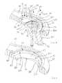
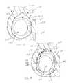
- the bone anchor 56is driven into the lower non-dynamized throughbore 52 in an oblique direction 70 at an oblique angle ⁇ relative to the bore central axis 72 to drive a shank 74 of the bone anchor 56 into a bone (not shown) disposed below the bone plate 12 .
- Driving the bone anchor 56 in direction 70also engages the head 76 of the bone anchor 56 against the seat 80 of the bone plate 12 and fixes the bone plate 12 to the bone.
Landscapes
- Health & Medical Sciences (AREA)
- Orthopedic Medicine & Surgery (AREA)
- Life Sciences & Earth Sciences (AREA)
- Surgery (AREA)
- Neurology (AREA)
- Heart & Thoracic Surgery (AREA)
- Engineering & Computer Science (AREA)
- Biomedical Technology (AREA)
- Nuclear Medicine, Radiotherapy & Molecular Imaging (AREA)
- Medical Informatics (AREA)
- Molecular Biology (AREA)
- Animal Behavior & Ethology (AREA)
- General Health & Medical Sciences (AREA)
- Public Health (AREA)
- Veterinary Medicine (AREA)
- Surgical Instruments (AREA)
Abstract
Description
Claims (72)
Priority Applications (3)
| Application Number | Priority Date | Filing Date | Title |
|---|---|---|---|
| US13/069,354US8900277B2 (en) | 2004-02-26 | 2011-03-22 | Bone plate system |
| US14/554,960US10166051B2 (en) | 2004-02-26 | 2014-11-26 | Bone plate system |
| US16/217,652US11129653B2 (en) | 2004-02-26 | 2018-12-12 | Bone plate system |
Applications Claiming Priority (4)
| Application Number | Priority Date | Filing Date | Title |
|---|---|---|---|
| US54814004P | 2004-02-26 | 2004-02-26 | |
| US10/973,891US7740649B2 (en) | 2004-02-26 | 2004-10-26 | Bone plate system and methods |
| US11/259,714US7909859B2 (en) | 2004-02-26 | 2005-10-26 | Bone plate system and methods |
| US13/069,354US8900277B2 (en) | 2004-02-26 | 2011-03-22 | Bone plate system |
Related Parent Applications (1)
| Application Number | Title | Priority Date | Filing Date |
|---|---|---|---|
| US11/259,714Continuation-In-PartUS7909859B2 (en) | 2004-02-26 | 2005-10-26 | Bone plate system and methods |
Related Child Applications (1)
| Application Number | Title | Priority Date | Filing Date |
|---|---|---|---|
| US14/554,960ContinuationUS10166051B2 (en) | 2004-02-26 | 2014-11-26 | Bone plate system |
Publications (2)
| Publication Number | Publication Date |
|---|---|
| US20120065690A1 US20120065690A1 (en) | 2012-03-15 |
| US8900277B2true US8900277B2 (en) | 2014-12-02 |
Family
ID=45807436
Family Applications (3)
| Application Number | Title | Priority Date | Filing Date |
|---|---|---|---|
| US13/069,354Expired - LifetimeUS8900277B2 (en) | 2004-02-26 | 2011-03-22 | Bone plate system |
| US14/554,960Active2027-01-01US10166051B2 (en) | 2004-02-26 | 2014-11-26 | Bone plate system |
| US16/217,652Expired - LifetimeUS11129653B2 (en) | 2004-02-26 | 2018-12-12 | Bone plate system |
Family Applications After (2)
| Application Number | Title | Priority Date | Filing Date |
|---|---|---|---|
| US14/554,960Active2027-01-01US10166051B2 (en) | 2004-02-26 | 2014-11-26 | Bone plate system |
| US16/217,652Expired - LifetimeUS11129653B2 (en) | 2004-02-26 | 2018-12-12 | Bone plate system |
Country Status (1)
| Country | Link |
|---|---|
| US (3) | US8900277B2 (en) |
Cited By (11)
| Publication number | Priority date | Publication date | Assignee | Title |
|---|---|---|---|---|
| US20130309632A1 (en)* | 2011-02-02 | 2013-11-21 | Mid Corp. | System, apparatus and method for implementing implants |
| US8807295B2 (en) | 2009-06-30 | 2014-08-19 | Continental Teves Ag & Co. Ohg | Brake caliper of a disk brake |
| US9504584B1 (en) | 2011-01-28 | 2016-11-29 | Nuvasive, Inc. | Spinal fusion implant and related methods |
| US10166051B2 (en) | 2004-02-26 | 2019-01-01 | Pioneer Surgical Technology, Inc. | Bone plate system |
| US10537666B2 (en) | 2015-05-18 | 2020-01-21 | Stryker European Holdings I, Llc | Partially resorbable implants and methods |
| US10603182B2 (en) | 2015-01-14 | 2020-03-31 | Stryker European Holdings I, Llc | Spinal implant with fluid delivery capabilities |
| US10835388B2 (en) | 2017-09-20 | 2020-11-17 | Stryker European Operations Holdings Llc | Spinal implants |
| US11000386B2 (en) | 2015-01-14 | 2021-05-11 | Stryker European Holdings I, Llc | Spinal implant with porous and solid surfaces |
| US11026726B2 (en) | 2012-06-29 | 2021-06-08 | K2M, Inc. | Minimal-profile anterior cervical plate and cage apparatus and method of using same |
| US11039865B2 (en) | 2018-03-02 | 2021-06-22 | Stryker European Operations Limited | Bone plates and associated screws |
| US11744619B2 (en) | 2018-04-06 | 2023-09-05 | K2M, Inc. | Faceted bone plate |
Families Citing this family (21)
| Publication number | Priority date | Publication date | Assignee | Title |
|---|---|---|---|---|
| US8425569B2 (en)* | 2010-05-19 | 2013-04-23 | Transcorp, Inc. | Implantable vertebral frame systems and related methods for spinal repair |
| DE102011051975B4 (en)* | 2011-07-20 | 2023-01-12 | Ulrich Gmbh & Co. Kg | implant |
| US9351768B2 (en)* | 2011-08-26 | 2016-05-31 | Life Spine, Inc. | Bone screw retention in a spinal implant |
| US9642652B2 (en)* | 2013-02-13 | 2017-05-09 | Choice Spine, Lp | Variable angle bone plate with semi-constrained articulating screw |
| US9943341B2 (en)* | 2013-07-16 | 2018-04-17 | K2M, Llc | Retention plate member for a spinal plate system |
| AU2014365821B2 (en)* | 2013-12-20 | 2019-10-03 | Crossroads Extremity Systems, Llc | Polyaxial locking hole |
| US9913672B2 (en)* | 2014-05-28 | 2018-03-13 | Genesys Spine | Resiliant spinal plate system |
| US11202626B2 (en) | 2014-07-10 | 2021-12-21 | Crossroads Extremity Systems, Llc | Bone implant with means for multi directional force and means of insertion |
| JP2017529886A (en) | 2014-07-10 | 2017-10-12 | クロスローズ エクストリミティ システムズ リミテッド ライアビリティ カンパニー | Bone implant and means of insertion |
| WO2017011589A1 (en) | 2015-07-13 | 2017-01-19 | Crossroads Extremity Systems, Llc | Bone plates with dynamic elements |
| EP3468491B1 (en)* | 2016-06-09 | 2020-12-09 | Stryker European Holdings I, LLC | Bone screw system |
| US9918750B2 (en)* | 2016-08-04 | 2018-03-20 | Osseus Fusion Systems, Llc | Method, system, and apparatus for temporary anterior cervical plate fixation |
| US11864753B2 (en) | 2017-02-06 | 2024-01-09 | Crossroads Extremity Systems, Llc | Implant inserter |
| EP3579762B1 (en) | 2017-02-07 | 2024-06-26 | Crossroads Extremity Systems, LLC | Counter-torque implant |
| USD928589S1 (en)* | 2018-02-12 | 2021-08-24 | Bematrix Bvba | Pin plate |
| KR102278169B1 (en)* | 2019-08-07 | 2021-07-20 | 주식회사 지비에스커먼웰스 | Spinal plate system for invertebral body fixation |
| US11877779B2 (en) | 2020-03-26 | 2024-01-23 | Xtant Medical Holdings, Inc. | Bone plate system |
| US12059183B2 (en) | 2020-07-31 | 2024-08-13 | Crossroads Extremity Systems, Llc | Bone plates with dynamic elements and screws |
| USD961081S1 (en) | 2020-11-18 | 2022-08-16 | Crossroads Extremity Systems, Llc | Orthopedic implant |
| USD993744S1 (en)* | 2021-07-21 | 2023-08-01 | C & H International Corporation | Siding splice joint |
| CN113786234B (en)* | 2021-10-18 | 2025-08-26 | 上海长征医院 | Anterior cervical spine plate, elevator, and internal fixation system for ACAF |
Citations (293)
| Publication number | Priority date | Publication date | Assignee | Title |
|---|---|---|---|---|
| US434503A (en) | 1890-08-19 | William corry | ||
| US556642A (en) | 1896-03-17 | Nut-lock | ||
| US807396A (en) | 1905-06-28 | 1905-12-12 | Henry L Newton | Wrench. |
| US872897A (en) | 1907-08-31 | 1907-12-03 | John W Chapman | Nut-lock. |
| US951680A (en) | 1909-06-28 | 1910-03-08 | Henry William Dunlap | Safety-elevator. |
| US951800A (en) | 1909-11-01 | 1910-03-15 | Henry C Lacey | Nut-lock. |
| US1084680A (en) | 1913-03-05 | 1914-01-20 | Arnold Heinrich Wegener | Nut-lock. |
| US1385780A (en) | 1919-09-10 | 1921-07-26 | Flannery Bolt Co | Staybolt structure |
| US1409157A (en) | 1920-01-20 | 1922-03-14 | Flannery Bolt Co | Stay-bolt structure |
| US1756239A (en) | 1929-02-12 | 1930-04-29 | Paul B Chojnacki | Trailer |
| US1907506A (en) | 1931-06-20 | 1933-05-09 | Delco Remy Corp | Retainer clip |
| US1980336A (en) | 1933-05-17 | 1934-11-13 | Pratt & Whitney Co | Chuck retaining means |
| US2248054A (en) | 1939-06-07 | 1941-07-08 | Becker Joseph | Screw driver |
| US2401856A (en) | 1943-05-06 | 1946-06-11 | Automotive Prod Co Ltd | Retaining washer and the like |
| FR994718A (en) | 1949-09-07 | 1951-11-21 | Manufacturing process for phosphate fertilizers | |
| US2580821A (en) | 1950-10-21 | 1952-01-01 | Nicola Toufick | Spring impactor bone plate |
| US2780223A (en) | 1955-05-17 | 1957-02-05 | Paul B Haggland | Fracture plate |
| US3100516A (en) | 1959-02-06 | 1963-08-13 | Ingersoll Rand Co | Threaded members locked by expanded tubular locking pin |
| US3244170A (en) | 1962-11-23 | 1966-04-05 | Robert T Mcelvenny | Compression type bone splint |
| US3426364A (en) | 1966-08-25 | 1969-02-11 | Colorado State Univ Research F | Prosthetic appliance for replacing one or more natural vertebrae |
| US3534731A (en) | 1967-08-18 | 1970-10-20 | Jean Nicolas Muller | Means for joining parts of fractured bones |
| US3596656A (en) | 1969-01-21 | 1971-08-03 | Bernd B Kaute | Fracture fixation device |
| US3659595A (en) | 1969-10-22 | 1972-05-02 | Edward J Haboush | Compensating plates for bone fractures |
| US3695259A (en) | 1970-11-10 | 1972-10-03 | Clyde E Yost | Bone plate |
| US3741205A (en) | 1971-06-14 | 1973-06-26 | K Markolf | Bone fixation plate |
| US3842825A (en) | 1973-11-12 | 1974-10-22 | R Wagner | Hip fixation device |
| USRE28841E (en) | 1966-06-22 | 1976-06-08 | Synthes A.G. | Osteosynthetic pressure plate construction |
| US4003376A (en) | 1975-08-25 | 1977-01-18 | Bio-Dynamics, Inc. | Apparatus for straightening the spinal column |
| US4037980A (en) | 1975-12-24 | 1977-07-26 | Haentjens Walter D | Pump coupling |
| US4113227A (en) | 1977-04-05 | 1978-09-12 | Marine Moisture Control Co., Inc. | Cam lock with vertical plunger |
| DE2933141C3 (en) | 1978-10-06 | 1981-12-17 | Gebrüder Sulzer AG, 8401 Winterthur | Anchoring pin for a nail-like sliding surface implant |
| US4334599A (en) | 1980-08-18 | 1982-06-15 | The Bendix Corporation | Disc brake and mounting pin assembly therefor |
| US4388921A (en) | 1980-05-28 | 1983-06-21 | Institut Straumann Ag | Device comprising a plate and screws for fastening a plate to a bone |
| FR2519857B1 (en) | 1982-01-19 | 1984-03-23 | Butel Jean | |
| USRE31628E (en) | 1966-06-22 | 1984-07-10 | Synthes Ag | Osteosynthetic pressure plate construction |
| US4473068A (en) | 1982-01-18 | 1984-09-25 | Indong Oh | Trochanteric basket |
| US4484570A (en) | 1980-05-28 | 1984-11-27 | Synthes Ltd. | Device comprising an implant and screws for fastening said implant to a bone, and a device for connecting two separated pieces of bone |
| US4493317A (en) | 1980-11-20 | 1985-01-15 | Synthes Ltd. (U.S.A.) | Surgical compression plate and drill guide |
| US4503848A (en) | 1981-04-08 | 1985-03-12 | Aesculap-Werke Aktiengesellschaft | Osteosynthesis plate |
| US4524765A (en) | 1981-12-09 | 1985-06-25 | Zbikowski Juan | Functional attachment system for osteosynthesis by means of compression plates |
| FR2435243B1 (en) | 1978-09-07 | 1985-06-28 | Tornier Sa | IMPROVEMENTS IN PLATES FOR OSTEOSYNTHESIS |
| FR2556583B1 (en) | 1983-12-19 | 1986-04-18 | Inst Nat Sante Rech Med | OSTEOSYNTHESIS PLATES FOR BONE DEROTATION, ESPECIALLY FEMORAL DEROTATION |
| US4599086A (en) | 1985-06-07 | 1986-07-08 | Doty James R | Spine stabilization device and method |
| WO1988003781A1 (en) | 1986-11-25 | 1988-06-02 | Synthes Ag | Osteosynthetic device |
| US4762122A (en) | 1987-02-06 | 1988-08-09 | Barclay Slocum | Device and method for pelvic osteotomy fixation |
| SU1424824A1 (en) | 1987-03-30 | 1988-09-23 | Устиновский Государственный Медицинский Институт | Arrangement for osteosynthesis |
| US4776330A (en) | 1986-06-23 | 1988-10-11 | Pfizer Hospital Products Group, Inc. | Modular femoral fixation system |
| US4794918A (en) | 1985-05-06 | 1989-01-03 | Dietmar Wolter | Bone plate arrangement |
| EP0179695B1 (en) | 1984-09-26 | 1989-03-29 | Pierre Kehr | Vertebral prosthesis, in particular for cervical vertebrae |
| US4892545A (en) | 1988-07-14 | 1990-01-09 | Ohio Medical Instrument Company, Inc. | Vertebral lock |
| US4904261A (en) | 1987-08-06 | 1990-02-27 | A. W. Showell (Surgicraft) Limited | Spinal implants |
| US4943292A (en) | 1989-11-08 | 1990-07-24 | National Research Council Of Canada | Plate for broken bone fixation |
| US4955908A (en) | 1987-07-09 | 1990-09-11 | Sulzer Brothers Limited | Metallic intervertebral prosthesis |
| US4957497A (en) | 1984-10-27 | 1990-09-18 | Thomas Hoogland | Device for osteosynthesis |
| US4964403A (en) | 1986-12-19 | 1990-10-23 | Huta Baildon Przedsiebiorstwo Panstwowe Katowice | Stabilizer for the treatment of the fracture of the neck and upper metaphysis of the femur |
| EP0410309A1 (en) | 1989-07-20 | 1991-01-30 | Lutz Biedermann | Stabilising element for bones |
| US5002544A (en) | 1987-12-02 | 1991-03-26 | Synthes (U.S.A.) | Osteosynthetic pressure plate osteosynthetic compression plate |
| WO1991003994A1 (en) | 1989-09-21 | 1991-04-04 | Krasnodarsky Kraevoi Sovet Vsesojuznogo Obschestva Izobretatelei I Ratsionalizatorov | Device for fitting a prosthesis for an extremity |
| US5053036A (en) | 1987-11-03 | 1991-10-01 | Synthes (U.S.A.) | Point contact bone compression plate |
| US5057111A (en) | 1987-11-04 | 1991-10-15 | Park Joon B | Non-stress-shielding bone fracture healing device |
| EP0455255A1 (en) | 1990-05-04 | 1991-11-06 | Witold Ramotowski | A plate-type bone stabilizer |
| US5085660A (en) | 1990-11-19 | 1992-02-04 | Lin Kwan C | Innovative locking plate system |
| US5108395A (en) | 1989-09-18 | 1992-04-28 | Societe De Fabrication De Materiel Orthopedique - Sofamor | Implant for anterior dorsolumbar spinal osteosynthesis, intended for the correction of kyphoses |
| US5113685A (en) | 1991-01-28 | 1992-05-19 | Acromed Corporation | Apparatus for contouring spine plates and/or rods |
| US5127912A (en) | 1990-10-05 | 1992-07-07 | R. Charles Ray | Sacral implant system |
| US5127914A (en) | 1989-02-10 | 1992-07-07 | Calderale Pasquale M | Osteosynthesis means for the connection of bone fracture segments |
| US5129899A (en) | 1991-03-27 | 1992-07-14 | Smith & Nephew Richards Inc. | Bone fixation apparatus |
| US5129903A (en) | 1988-06-18 | 1992-07-14 | Luhr Hans Georg | Bone plate |
| US5139498A (en) | 1988-10-18 | 1992-08-18 | Astudillo Ley Freddy R | Device for closing sternum in heart surgery |
| US5147361A (en) | 1989-11-29 | 1992-09-15 | Asahi Kogaku Kogyo Kabushiki Kaisha | Vertebral connecting plate |
| US5147360A (en) | 1990-02-19 | 1992-09-15 | Societe De Fabrication De Materiel Orthopedique | Osteosynthesis device for the correction of spinal curvatures |
| US5151103A (en) | 1987-11-03 | 1992-09-29 | Synthes (U.S.A.) | Point contact bone compression plate |
| US5180381A (en) | 1991-09-24 | 1993-01-19 | Aust Gilbert M | Anterior lumbar/cervical bicortical compression plate |
| US5190544A (en) | 1986-06-23 | 1993-03-02 | Pfizer Hospital Products Group, Inc. | Modular femoral fixation system |
| EP0242842B1 (en) | 1986-04-21 | 1993-03-03 | Dietmar Prof. Dr. Wolter | Bone plate arrangement |
| US5234431A (en) | 1991-04-03 | 1993-08-10 | Waldemar Link Gmbh & Co. | Bone plate arrangement |
| US5261910A (en) | 1992-02-19 | 1993-11-16 | Acromed Corporation | Apparatus for maintaining spinal elements in a desired spatial relationship |
| US5269784A (en) | 1991-12-10 | 1993-12-14 | Synthes (U.S.A.) | Screw nut for plate osteosynthesis |
| US5275601A (en) | 1991-09-03 | 1994-01-04 | Synthes (U.S.A) | Self-locking resorbable screws and plates for internal fixation of bone fractures and tendon-to-bone attachment |
| US5304179A (en) | 1993-06-17 | 1994-04-19 | Amei Technologies Inc. | System and method for installing a spinal fixation system at variable angles |
| US5324290A (en) | 1992-09-24 | 1994-06-28 | Danek Medical, Inc. | Anterior thoracolumbar plate |
| US5326206A (en) | 1993-04-19 | 1994-07-05 | Northrop Corporation | Method for compensating for bolt hole misalignment and bolt assemblies therefor |
| US5330535A (en) | 1991-03-07 | 1994-07-19 | Sulzer Brothers Limited | Screw-nut for screwing implants together |
| WO1994017744A1 (en) | 1993-02-05 | 1994-08-18 | Danek Medical, Inc. | Anterior cervical plating system |
| US5344421A (en) | 1993-07-16 | 1994-09-06 | Amei Technologies Inc. | Apparatus and method for adjusting a bone plate |
| US5346492A (en) | 1992-03-30 | 1994-09-13 | Timesh, Inc. | Perforated metallic panels and strips for internal fixation of bone fractures and for reconstructive surgery |
| US5380323A (en) | 1993-06-16 | 1995-01-10 | Advanced Spine Fixation Systems, Inc. | Clamps for spinal fixation systems |
| US5382248A (en) | 1992-09-10 | 1995-01-17 | H. D. Medical, Inc. | System and method for stabilizing bone segments |
| US5397364A (en) | 1993-10-12 | 1995-03-14 | Danek Medical, Inc. | Anterior interbody fusion device |
| US5397363A (en) | 1992-08-11 | 1995-03-14 | Gelbard; Steven D. | Spinal stabilization implant system |
| US5423826A (en) | 1993-02-05 | 1995-06-13 | Danek Medical, Inc. | Anterior cervical plate holder/drill guide and method of use |
| WO1995025474A1 (en) | 1994-03-22 | 1995-09-28 | Biedermann Motech Gmbh | Stabilising arrangement, in particular for stabilising the spinal column |
| US5454769A (en) | 1995-03-09 | 1995-10-03 | Chen; Ping | Wrist and forearm exercise apparatus with improved resistance adjustment device |
| US5458641A (en) | 1993-09-08 | 1995-10-17 | Ramirez Jimenez; Juan J. | Vertebral body prosthesis |
| US5468242A (en) | 1993-11-19 | 1995-11-21 | Leibinger Gmbh | Form-fitting mesh implant |
| WO1995031941A1 (en) | 1994-05-25 | 1995-11-30 | American Cyanamid Company | Vertebral fusion system with expandable anchor |
| US5478342A (en) | 1994-06-30 | 1995-12-26 | Spinetech, Inc. | Reversible bone screw lock |
| US5486176A (en) | 1991-03-27 | 1996-01-23 | Smith & Nephew Richards, Inc. | Angled bone fixation apparatus |
| WO1996005778A1 (en) | 1994-08-23 | 1996-02-29 | Spinetech, Inc. | Cervical spine stabilization system |
| WO1996008206A1 (en) | 1994-09-15 | 1996-03-21 | Smith & Nephew Richards Inc. | Osteosynthesis apparatus |
| US5501684A (en) | 1992-06-25 | 1996-03-26 | Synthes (U.S.A.) | Osteosynthetic fixation device |
| US5520690A (en) | 1995-04-13 | 1996-05-28 | Errico; Joseph P. | Anterior spinal polyaxial locking screw plate assembly |
| US5520696A (en) | 1994-09-27 | 1996-05-28 | Mitek Surgical Products, Inc. | Bone anchor installation tool |
| US5522899A (en) | 1988-06-28 | 1996-06-04 | Sofamor Danek Properties, Inc. | Artificial spinal fusion implants |
| US5527311A (en) | 1991-11-13 | 1996-06-18 | Howmedica Gmbh | Support for the human spine |
| US5534027A (en) | 1993-06-21 | 1996-07-09 | Zimmer, Inc. | Method for providing a barrier to the advancement of wear debris in an orthopaedic implant assembly |
| US5549612A (en) | 1992-11-25 | 1996-08-27 | Codman & Shurtleff, Inc. | Osteosynthesis plate system |
| WO1996029948A1 (en) | 1995-03-27 | 1996-10-03 | Synthes Ag, Chur | Bone plate |
| US5569251A (en) | 1993-07-16 | 1996-10-29 | Bhc Engineering, L.P. | Implant device and method of installing |
| US5569247A (en) | 1995-03-27 | 1996-10-29 | Smith & Nephew Richards, Inc. | Enhanced variable angle bone bolt |
| US5571109A (en) | 1993-08-26 | 1996-11-05 | Man Ceramics Gmbh | System for the immobilization of vertebrae |
| US5578034A (en) | 1995-06-07 | 1996-11-26 | Danek Medical, Inc. | Apparatus for preventing screw backout in a bone plate fixation system |
| US5601553A (en) | 1994-10-03 | 1997-02-11 | Synthes (U.S.A.) | Locking plate and bone screw |
| US5603713A (en) | 1991-09-24 | 1997-02-18 | Aust; Gilbert M. | Anterior lumbar/cervical bicortical compression plate |
| US5607428A (en) | 1995-05-01 | 1997-03-04 | Lin; Kwan C. | Orthopedic fixation device having a double-threaded screw |
| US5620443A (en) | 1995-01-25 | 1997-04-15 | Danek Medical, Inc. | Anterior screw-rod connector |
| WO1997022306A1 (en) | 1995-12-20 | 1997-06-26 | Smith & Nephew Inc. | Osteosynthesis apparatus |
| US5647872A (en) | 1991-01-14 | 1997-07-15 | Donald Chow | Spinal support plates |
| US5651651A (en) | 1996-08-16 | 1997-07-29 | Spencer; Paul E. | Tamper resistant fastening assembly and method of use |
| US5653708A (en) | 1992-12-28 | 1997-08-05 | Advanced Spine Fixation Systems, Inc. | Cervical spine rod fixation system |
| US5667513A (en) | 1995-06-07 | 1997-09-16 | Smith & Nephew Dyonics Inc. | Soft tissue anchor delivery apparatus |
| US5676703A (en) | 1994-05-11 | 1997-10-14 | Gelbard; Steven D. | Spinal stabilization implant system |
| US5681312A (en) | 1996-05-31 | 1997-10-28 | Acromed Corporation | Spine construct with band clamp |
| US5690631A (en) | 1996-09-11 | 1997-11-25 | Walter Lorenz Surgical, Inc. | Multi-configurable plating system |
| FR2740321B3 (en) | 1995-10-27 | 1997-12-05 | Fuentes Jean Marc | ANTERIOR OSTEOSYNTHESIS DEVICE FOR CERVICAL VERTEBRES |
| US5704936A (en) | 1992-04-10 | 1998-01-06 | Eurosurgical | Spinal osteosynthesis device |
| US5707372A (en) | 1996-07-11 | 1998-01-13 | Third Millennium Engineering, Llc. | Multiple node variable length cross-link device |
| US5713900A (en) | 1996-05-31 | 1998-02-03 | Acromed Corporation | Apparatus for retaining bone portions in a desired spatial relationship |
| US5735850A (en) | 1995-02-17 | 1998-04-07 | Sulzer Medizinaltechnik Ag | Fastening system for pedicel screws |
| US5735899A (en) | 1994-12-08 | 1998-04-07 | Vanderbilt University | Low profile intraosseous anterior spinal fusion system and method |
| US5735853A (en) | 1994-06-17 | 1998-04-07 | Olerud; Sven | Bone screw for osteosynthesis |
| US5741258A (en) | 1993-01-25 | 1998-04-21 | Synthes (U.S.A.) | Lock washer for bone plate osteosynthesis |
| US5766176A (en) | 1996-09-11 | 1998-06-16 | Walter Lorenz Surgical, Inc. | Formable mesh |
| WO1998034556A1 (en) | 1997-02-11 | 1998-08-13 | Michelson Gary K | Skeletal plating system |
| WO1998034553A1 (en) | 1997-02-11 | 1998-08-13 | Michelson Gary K | Anterior cervical plating system, instrumentation, and method of installation |
| US5797912A (en) | 1995-09-22 | 1998-08-25 | Terray Corporation | Washer for use with a bone screw |
| US5800433A (en) | 1996-05-31 | 1998-09-01 | Acromed Corporation | Spinal column retaining apparatus |
| US5807396A (en) | 1995-12-22 | 1998-09-15 | Howmedica Leibinger Gmbh | Bone plate with conical holes |
| US5810823A (en) | 1994-09-12 | 1998-09-22 | Synthes (U.S.A.) | Osteosynthetic bone plate and lock washer |
| US5814048A (en) | 1996-05-03 | 1998-09-29 | Sofamor Danek Properties, Inc. | Cranioplasty plates and method of installation |
| US5840078A (en) | 1995-03-01 | 1998-11-24 | Yerys; Paul | Method and apparatus for mechanical attachment of soft tissue to bone tissue |
| US5843082A (en) | 1996-05-31 | 1998-12-01 | Acromed Corporation | Cervical spine stabilization method and system |
| WO1999004718A1 (en) | 1997-07-28 | 1999-02-04 | Dimso (Distribution Medicale Du Sud-Ouest) | Implant, in particular front cervical plate |
| WO1998051226A3 (en) | 1997-05-15 | 1999-02-18 | Sdgi Holdings Inc | Anterior cervical plating system |
| US5879389A (en) | 1995-04-07 | 1999-03-09 | Koshino; Tomihisa | Medical substituting element for hard tissues and artificial joint |
| EP0903113A2 (en) | 1997-09-09 | 1999-03-24 | Fuchs, Werner | Fixed-angle screw connection for bone plates |
| US5888221A (en) | 1992-08-11 | 1999-03-30 | Gelbard; Steven D. | Spinal stabilization implant system |
| WO1999021502A1 (en) | 1997-10-24 | 1999-05-06 | Bray Robert S Jr | Bone plate and bone screw guide mechanism |
| US5904683A (en) | 1998-07-10 | 1999-05-18 | Sulzer Spine-Tech Inc. | Anterior cervical vertebral stabilizing device |
| US5951558A (en) | 1998-04-22 | 1999-09-14 | Fiz; Daniel | Bone fixation device |
| US5951557A (en) | 1997-12-30 | 1999-09-14 | Luter; Dennis W. | Bone plate |
| US5954722A (en) | 1997-07-29 | 1999-09-21 | Depuy Acromed, Inc. | Polyaxial locking plate |
| US5964762A (en) | 1996-09-17 | 1999-10-12 | Biedermann; Lutz | Bone plate |
| US5976141A (en) | 1995-02-23 | 1999-11-02 | Synthes (U.S.A.) | Threaded insert for bone plate screw hole |
| US5980540A (en) | 1997-04-11 | 1999-11-09 | Kinamed, Inc. | Perforated cover for covering spaces in the cranium and conforming to the shape of the cranium |
| WO1999056653A1 (en) | 1998-04-30 | 1999-11-11 | Societe De Fabrication De Materiel Orthopedique (Sofamor) | Bone plate with bone screw securing means |
| US5984924A (en) | 1998-10-07 | 1999-11-16 | Isola Implants, Inc. | Bone alignment system having variable orientation bone anchors |
| US6017345A (en) | 1997-05-09 | 2000-01-25 | Spinal Innovations, L.L.C. | Spinal fixation plate |
| US6022350A (en) | 1996-05-13 | 2000-02-08 | Stryker France S.A. | Bone fixing device, in particular for fixing to the sacrum during osteosynthesis of the backbone |
| US6030389A (en) | 1997-08-04 | 2000-02-29 | Spinal Concepts, Inc. | System and method for stabilizing the human spine with a bone plate |
| US6039740A (en) | 1995-02-07 | 2000-03-21 | Olerud; Sven | Method and a device for implant locking |
| WO2000003653A3 (en) | 1998-07-14 | 2000-04-20 | Theken Surgical Llc | Bone fixation system |
| EP0995404A1 (en) | 1998-10-20 | 2000-04-26 | Industrias Quirurgicas De Levante | Cervical plate |
| US6090111A (en) | 1998-06-17 | 2000-07-18 | Surgical Dynamics, Inc. | Device for securing spinal rods |
| US6102912A (en) | 1997-05-29 | 2000-08-15 | Sofamor S.N.C. | Vertebral rod of constant section for spinal osteosynthesis instrumentations |
| US6106557A (en) | 1998-07-23 | 2000-08-22 | Howmedica Gmbh | Reconstruction system for vertebra |
| US6117173A (en) | 1995-12-07 | 2000-09-12 | Aesculap Ag & Co., Kg | Orthopaedic fixing system |
| US6129730A (en) | 1999-02-10 | 2000-10-10 | Depuy Acromed, Inc. | Bi-fed offset pitch bone screw |
| US6132434A (en) | 1996-11-07 | 2000-10-17 | Sdgi Holdings, Inc. | Multi-angle bone screw assembly using shape-memory technology |
| WO2000066011A1 (en) | 1999-05-05 | 2000-11-09 | Michelson Gary K | Screws of cortical bone and method of manufacture thereof |
| US6159213A (en) | 1998-10-02 | 2000-12-12 | Rogozinski; Chaim | Cervical plate |
| WO2000078238A1 (en) | 1999-06-17 | 2000-12-28 | Eurosurgical | Anti-slip device for an orthopedic implant |
| WO2000025689A9 (en) | 1998-10-29 | 2001-01-04 | Alphatec Mfg Inc | Fastening system with deformable set screw |
| WO2001001874A1 (en) | 1999-07-01 | 2001-01-11 | Spinevision S.A. | Vertebral osteosynthesis plate and osteosynthesis system |
| US6183476B1 (en) | 1998-06-26 | 2001-02-06 | Orto Maquet Gmbh & Co. Kg | Plate arrangement for osteosynthesis |
| US6189422B1 (en) | 1998-07-17 | 2001-02-20 | Karl Storz Gmbh & Co. Kg | Screwdriver |
| US6193720B1 (en) | 1998-11-30 | 2001-02-27 | Depuy Orthopaedics, Inc. | Cervical spine stabilization method and system |
| US6206882B1 (en) | 1999-03-30 | 2001-03-27 | Surgical Dynamics Inc. | Plating system for the spine |
| US6206881B1 (en) | 1995-09-06 | 2001-03-27 | Synthes (Usa) | Bone plate |
| WO2001026566A1 (en) | 1999-10-13 | 2001-04-19 | Sdgi Holdings, Inc. | Anterior cervical plating system and method |
| US6224602B1 (en) | 1999-10-11 | 2001-05-01 | Interpore Cross International | Bone stabilization plate with a secured-locking mechanism for cervical fixation |
| US6235032B1 (en) | 1996-08-22 | 2001-05-22 | Waldemar Link (Gmbh & Co) | Calcaneal bone plate |
| US6235033B1 (en) | 2000-04-19 | 2001-05-22 | Synthes (Usa) | Bone fixation assembly |
| US6241731B1 (en) | 1998-08-11 | 2001-06-05 | Daniel Fiz | Plate and screw assembly for fixing bones |
| US6258089B1 (en) | 1998-05-19 | 2001-07-10 | Alphatec Manufacturing, Inc. | Anterior cervical plate and fixation system |
| US6257593B1 (en) | 1999-05-14 | 2001-07-10 | Patrick Michel White | Stress induced interposed connector |
| WO2001049191A1 (en) | 2000-01-06 | 2001-07-12 | Spinal Concepts, Inc. | System and method for stabilizing the human spine with a bone plate |
| US6261291B1 (en) | 1999-07-08 | 2001-07-17 | David J. Talaber | Orthopedic implant assembly |
| US6261042B1 (en) | 1998-11-03 | 2001-07-17 | Textron Inc. | Quick-release fastener system |
| US20010014807A1 (en) | 1997-08-04 | 2001-08-16 | Erik J. Wagner | System and method for stabilizing the human spine with a bone plate |
| US20010021851A1 (en) | 1998-07-20 | 2001-09-13 | Roland Eberlein | Fastening assembly |
| US6293949B1 (en) | 2000-03-01 | 2001-09-25 | Sdgi Holdings, Inc. | Superelastic spinal stabilization system and method |
| US6306139B1 (en) | 1998-10-19 | 2001-10-23 | Scint'x | Intervertebral connection device with an anti-extraction device to prevent extraction of anchoring screws |
| WO2001082805A1 (en) | 2000-04-28 | 2001-11-08 | Synthes Ag Chur | Remotely aligned surgical drill guide |
| US6322562B1 (en) | 1998-12-19 | 2001-11-27 | Dietmar Wolter | Fixation system for bones |
| US20010047172A1 (en) | 1999-10-13 | 2001-11-29 | Foley Kevin T. | System and method for securing a plate to the spinal column |
| US20010047174A1 (en) | 2000-05-12 | 2001-11-29 | Cosimo Donno | Connection of a bone screw to a bone plate |
| US6328738B1 (en) | 1999-11-24 | 2001-12-11 | Loubert Suddaby | Anterior cervical fusion compression plate and screw guide |
| US6332887B1 (en) | 1999-04-06 | 2001-12-25 | Benjamin D. Knox | Spinal fusion instrumentation system |
| US6335034B1 (en) | 1995-09-29 | 2002-01-01 | L.A.M. Pharmaceutical Corporation | Topical drug preparations |
| US6342055B1 (en) | 1999-04-29 | 2002-01-29 | Theken Surgical Llc | Bone fixation system |
| US20020016595A1 (en) | 1999-05-05 | 2002-02-07 | Gary K. Michelson | Screws of cortical bone and method of manufacture thereof |
| US6361537B1 (en) | 2001-05-18 | 2002-03-26 | Cinci M. Anderson | Surgical plate with pawl and process for repair of a broken bone |
| US6364880B1 (en) | 1994-03-28 | 2002-04-02 | Gary Karlin Michelson | Spinal implant with bone screws |
| US20020045899A1 (en) | 1995-04-13 | 2002-04-18 | Errico Joseph P. | Anterior cervical plate having polyaxial locking screws and sliding coupling elements |
| US6379364B1 (en) | 2000-04-28 | 2002-04-30 | Synthes (Usa) | Dual drill guide for a locking bone plate |
| US6381806B1 (en) | 2001-01-12 | 2002-05-07 | Nifty Products, Inc. | Retainer assembly for positive retention of floor mat |
| WO2001026567A9 (en) | 1999-10-11 | 2002-05-10 | Interpore Cross Internat | Bone stabilization plate with a secured-locking mechanism for cervical fixation |
| US6391030B1 (en) | 1997-08-26 | 2002-05-21 | Spinal Concepts, Inc. | Surgical cable system and method |
| US20020065517A1 (en) | 2000-11-28 | 2002-05-30 | Paul Kamaljit S. | Bone support assembly |
| US20020068938A1 (en) | 2000-12-05 | 2002-06-06 | Jackson Roger P. | Removable gripping set screw |
| US6402759B1 (en) | 1998-12-11 | 2002-06-11 | Biohorizons Implant Systems, Inc. | Surgical fastener driver |
| US6402756B1 (en) | 2001-02-15 | 2002-06-11 | Third Millennium Engineering, Llc | Longitudinal plate assembly having an adjustable length |
| US6402755B1 (en) | 2000-12-21 | 2002-06-11 | Perumala Corporation | Plate system for bridging and stabilizing spaced apart bone segments |
| US6406478B1 (en) | 2001-05-24 | 2002-06-18 | Robert W. H. Kuo | Bone reinforcement plate for use on the spine |
| US20020077630A1 (en) | 2000-12-19 | 2002-06-20 | Chih-I Lin | Spinal fixation and retrieval device |
| US6413259B1 (en) | 2000-12-14 | 2002-07-02 | Blackstone Medical, Inc | Bone plate assembly including a screw retaining member |
| US6423068B1 (en) | 2000-10-18 | 2002-07-23 | Erhard Reisberg | Method and apparatus for mandibular osteosynthesis |
| WO2001089428A3 (en) | 2000-05-25 | 2002-08-08 | Sevrain Lionel C | Inter-vertebral disc prosthesis for rachis for an anterior surgery thereof |
| WO2001089400A3 (en) | 2000-05-25 | 2002-08-08 | Lionel C Sevrain | Anchoring system for fixing objects to bones |
| US20020111630A1 (en) | 2001-02-15 | 2002-08-15 | Ralph James D. | Longitudinal plate assembly having an adjustable length |
| US20020120272A1 (en) | 1998-06-17 | 2002-08-29 | Hansen Yuan | Device for securing spinal rods |
| US20020120271A1 (en) | 2001-02-27 | 2002-08-29 | Dixon Robert A. | Method and device for using extended interference fit screw shanks for spinal stabilization |
| US20020120268A1 (en) | 2001-02-21 | 2002-08-29 | Roger Berger | Occipital plate and system for spinal stabilization |
| US20020128654A1 (en) | 1998-02-18 | 2002-09-12 | Steger Shon D. | Method and apparatus for bone fracture fixation |
| WO2002076317A1 (en) | 2001-03-27 | 2002-10-03 | Ferree Bret A | Hinged anterior thoracic/lumbar plate |
| US20020151893A1 (en) | 2001-02-23 | 2002-10-17 | Santilli Albert N. | Cage plate for spinal fusion and method of operation |
| WO2002080789A1 (en) | 2001-04-05 | 2002-10-17 | Osteotech, Inc. | Bone fixation system and method |
| US20020151899A1 (en) | 2001-04-17 | 2002-10-17 | Bailey Kirk J. | Anterior cervical plating system |
| US20020151900A1 (en) | 2001-01-12 | 2002-10-17 | Craig Glascott | Polyaxial screw with improved locking |
| US20020156474A1 (en) | 2001-04-20 | 2002-10-24 | Michael Wack | Polyaxial locking plate |
| US20020161370A1 (en) | 1999-07-07 | 2002-10-31 | Robert Frigg | Bone screw with two-part screw head |
| US6478797B1 (en) | 2001-05-16 | 2002-11-12 | Kamaljit S. Paul | Spinal fixation device |
| US20020173790A1 (en) | 2000-09-22 | 2002-11-21 | Han Chang | Device of an anterior cervical plate with a peg and screw |
| US20020183747A1 (en) | 2001-05-30 | 2002-12-05 | Merries International Inc. | Spinal fixation apparatus |
| US20020183757A1 (en) | 2001-06-04 | 2002-12-05 | Michelson Gary K. | Dynamic single-lock anterior cervical plate system having non-detachably fastened and moveable segments, instrumentation, and method for installation thereof |
| US20020183755A1 (en) | 2001-06-04 | 2002-12-05 | Michelson Gary K. | Dynamic anterior cervical plate system having moveable segments, instrumentation, and method for installation thereof |
| US20020183754A1 (en) | 2001-06-04 | 2002-12-05 | Michelson Gary K. | Anterior cervical plate system having vertebral body engaging anchors, connecting plate, and method for installation thereof |
| US20020183756A1 (en) | 2001-06-04 | 2002-12-05 | Michelson Gary K. | Dynamic, modular, single-lock anterior cervical plate system, having assembleable and moveable segments, instrumentation, and method for installation thereof |
| US20020188296A1 (en) | 2001-06-06 | 2002-12-12 | Michelson Gary K. | Dynamic, modular, multilock anterior cervical plate system having detachably fastened assembleable and moveable segments, instrumentation, and method for installation thereof |
| US20030023242A1 (en) | 1999-04-28 | 2003-01-30 | Harrington James Frederick | Modular anterior cervical plate |
| EP1285632A1 (en) | 2001-08-09 | 2003-02-26 | Lafitt, S.A. | Anterior cervical plate and fixation system |
| US20030040749A1 (en) | 2001-08-24 | 2003-02-27 | Grabowski John J. | Bone fixation device |
| US6537319B2 (en) | 1997-02-12 | 2003-03-25 | Arthrex, Inc. | Method of loading tendons into the knee |
| US20030060828A1 (en) | 2001-06-06 | 2003-03-27 | Michelson Gary K. | Dynamic multilock anterior cervical plate system having non-detachably fastened and moveable segments, instrumentation, and method for installation thereof |
| US20030078583A1 (en) | 2001-10-23 | 2003-04-24 | Biedermann Motech Gmbh | Bone fixing device |
| US20030093082A1 (en) | 2000-06-26 | 2003-05-15 | Stryker Spine | Bone screw retaining system |
| FR2810532B1 (en) | 2000-06-26 | 2003-05-30 | Stryker Spine Sa | BONE IMPLANT WITH ANNULAR LOCKING MEANS |
| US20030105462A1 (en) | 2001-11-30 | 2003-06-05 | Haider Thomas T. | Poly axial cervical plate system |
| US6579290B1 (en) | 1997-11-29 | 2003-06-17 | Surgicraft Limited | Surgical implant and surgical fixing screw |
| EP1306058A3 (en) | 2001-10-25 | 2003-06-25 | Corin Limited | A surgical plate implant |
| US6585769B1 (en) | 1999-04-05 | 2003-07-01 | Howmedica Osteonics Corp. | Artificial spinal ligament |
| US20030130661A1 (en) | 2002-01-08 | 2003-07-10 | Osman Said G. | Uni-directional dynamic spinal fixation device |
| US6602257B1 (en) | 2002-06-24 | 2003-08-05 | Jeffrey J. Thramann | Cervical plate |
| US6605090B1 (en) | 2000-10-25 | 2003-08-12 | Sdgi Holdings, Inc. | Non-metallic implant devices and intra-operative methods for assembly and fixation |
| WO2003063714A3 (en) | 2002-02-01 | 2003-09-04 | Spinal Concepts Inc | Spinal plate system for stabilizing a portion of a spine |
| US6623486B1 (en) | 1999-09-13 | 2003-09-23 | Synthes (U.S.A.) | bone plating system |
| EP1346697A2 (en) | 2002-03-12 | 2003-09-24 | Spinal Innovations, Inc. | Bone plate and screw retaining mechanism |
| EP0988833B1 (en) | 1998-09-24 | 2003-10-01 | Centerpulse Orthopedics Ltd. | Osteosynthesis plate with multiple bone screws |
| US20030187509A1 (en) | 2002-04-01 | 2003-10-02 | Lemole G. Michael | Modulus plating system and method |
| US20030225409A1 (en) | 2002-02-01 | 2003-12-04 | Freid James M. | Spinal plate extender system and method |
| US20040030338A1 (en) | 2001-12-14 | 2004-02-12 | Paul Kamaljit S. | Spinal plate assembly |
| US20040087951A1 (en) | 2002-11-04 | 2004-05-06 | Khalili Farid Bruce | Fastener retention system |
| US20040127899A1 (en) | 2002-12-31 | 2004-07-01 | Konieczynski David D. | Bone plate and screw system allowing bi-directional attachment |
| US20040127896A1 (en) | 2002-10-28 | 2004-07-01 | Alan Lombardo | Bone plate assembly provided with screw locking mechanisms |
| US20040127900A1 (en) | 2002-12-31 | 2004-07-01 | Konieczynski David D. | Resilient bone plate and screw system allowing bi-directional assembly |
| US20040153069A1 (en) | 2001-12-14 | 2004-08-05 | Paul Kamaljit S. | Spinal plate assembly |
| US20040186482A1 (en) | 2003-03-21 | 2004-09-23 | Kolb Eric D. | Modular drill guide |
| US20040204717A1 (en) | 2003-04-09 | 2004-10-14 | Jonathan Fanger | Guide for spinal tools, implants, and devices |
| US20040204710A1 (en) | 2003-04-09 | 2004-10-14 | Tushar Patel | Drill guide and plate inserter |
| US20040204716A1 (en) | 2003-04-09 | 2004-10-14 | Jonathan Fanger | Drill guide with alignment feature |
| US20040220571A1 (en) | 1998-04-30 | 2004-11-04 | Richard Assaker | Bone plate assembly |
| WO2003071966B1 (en) | 2002-02-25 | 2004-12-16 | Dzung H Dinh | Methods and apparatuses for promoting fusion of vertebrae |
| US20050049593A1 (en) | 2003-09-03 | 2005-03-03 | Duong Lan Anh Nguyen | Bone plate with captive clips |
| US20050192577A1 (en)* | 2004-02-26 | 2005-09-01 | Pioneer Laboratories, Inc. | Bone plate system and methods |
| US20050283152A1 (en) | 2004-06-17 | 2005-12-22 | Lindemann Gary S | Method and apparatus for retaining screws in a plate |
| US7008426B2 (en) | 2001-12-14 | 2006-03-07 | Paul Kamaljit S | Bone treatment plate assembly |
| US7025761B2 (en) | 1992-08-10 | 2006-04-11 | Intultive Surgical | Method and apparatus for performing minimally invasive cardiac procedures |
| US7025769B1 (en) | 2002-06-04 | 2006-04-11 | Nuvasive, Inc. | Surgical fixation system and related methods |
| US7048739B2 (en) | 2002-12-31 | 2006-05-23 | Depuy Spine, Inc. | Bone plate and resilient screw system allowing bi-directional assembly |
| US20060122602A1 (en) | 2004-12-08 | 2006-06-08 | Depuy Spine, Inc. | Hybrid spinal plates |
| US20060122604A1 (en) | 2004-12-08 | 2006-06-08 | Depuy Spine, Inc. | Locking bone screw and spinal plate system |
| US7077843B2 (en) | 2002-06-24 | 2006-07-18 | Lanx, Llc | Cervical plate |
| US20060200147A1 (en) | 2005-02-18 | 2006-09-07 | Ensign Michael D | Orthopedic plate system and method for using the same |
| US20060217725A1 (en) | 2005-03-11 | 2006-09-28 | Suh Sean S | Translational plate with spring beam retainer |
| US20060229620A1 (en) | 2005-03-03 | 2006-10-12 | Accin Corporation | Method and apparatus for providing a retainer for a bone stabilization device |
| WO2006055156A3 (en) | 2004-11-16 | 2007-01-18 | Depuy Spine Inc | Spinal plate system and method of use |
| US7452370B2 (en) | 2005-04-29 | 2008-11-18 | Warsaw Orthopedic, Inc | Apparatus for retaining a bone anchor in a bone plate and method for use thereof |
| WO2009052318A2 (en) | 2007-10-16 | 2009-04-23 | Robinson James C | Bone screw retaining and removal system |
| US20090187218A1 (en) | 2008-01-17 | 2009-07-23 | Amedica Corporation | Bone fixation plate with wire members for resisting back out of bone anchors |
| US7785327B1 (en)* | 2002-07-05 | 2010-08-31 | Theken Spine, Llc | Fixed and variable locking fixation assembly |
| US8066751B2 (en)* | 2006-09-14 | 2011-11-29 | Jean-Pierre Podgorski | Implantable orthopaedic device, in particular for the cervical spine |
| US8496693B2 (en) | 2007-10-16 | 2013-07-30 | Amendia Inc. | Bone screw retaining and removal system |
Family Cites Families (6)
| Publication number | Priority date | Publication date | Assignee | Title |
|---|---|---|---|---|
| GB191128864A (en) | 1911-12-21 | 1912-05-30 | Lucien Luttrell Miner | Improvements in Metal Bracing Plates for Fractured Bones. |
| CA2471843C (en) | 2001-12-24 | 2011-04-12 | Synthes (U.S.A.) | Device for osteosynthesis |
| US8900277B2 (en) | 2004-02-26 | 2014-12-02 | Pioneer Surgical Technology, Inc. | Bone plate system |
| WO2010070154A1 (en) | 2008-12-18 | 2010-06-24 | Surgival Co., S.A. | Locking device in screw-retained plates for medical use |
| US9943341B2 (en) | 2013-07-16 | 2018-04-17 | K2M, Llc | Retention plate member for a spinal plate system |
| US9913672B2 (en) | 2014-05-28 | 2018-03-13 | Genesys Spine | Resiliant spinal plate system |
- 2011
- 2011-03-22USUS13/069,354patent/US8900277B2/ennot_activeExpired - Lifetime
- 2014
- 2014-11-26USUS14/554,960patent/US10166051B2/enactiveActive
- 2018
- 2018-12-12USUS16/217,652patent/US11129653B2/ennot_activeExpired - Lifetime
Patent Citations (424)
| Publication number | Priority date | Publication date | Assignee | Title |
|---|---|---|---|---|
| US434503A (en) | 1890-08-19 | William corry | ||
| US556642A (en) | 1896-03-17 | Nut-lock | ||
| US807396A (en) | 1905-06-28 | 1905-12-12 | Henry L Newton | Wrench. |
| US872897A (en) | 1907-08-31 | 1907-12-03 | John W Chapman | Nut-lock. |
| US951680A (en) | 1909-06-28 | 1910-03-08 | Henry William Dunlap | Safety-elevator. |
| US951800A (en) | 1909-11-01 | 1910-03-15 | Henry C Lacey | Nut-lock. |
| US1084680A (en) | 1913-03-05 | 1914-01-20 | Arnold Heinrich Wegener | Nut-lock. |
| US1385780A (en) | 1919-09-10 | 1921-07-26 | Flannery Bolt Co | Staybolt structure |
| US1409157A (en) | 1920-01-20 | 1922-03-14 | Flannery Bolt Co | Stay-bolt structure |
| US1756239A (en) | 1929-02-12 | 1930-04-29 | Paul B Chojnacki | Trailer |
| US1907506A (en) | 1931-06-20 | 1933-05-09 | Delco Remy Corp | Retainer clip |
| US1980336A (en) | 1933-05-17 | 1934-11-13 | Pratt & Whitney Co | Chuck retaining means |
| US2248054A (en) | 1939-06-07 | 1941-07-08 | Becker Joseph | Screw driver |
| US2401856A (en) | 1943-05-06 | 1946-06-11 | Automotive Prod Co Ltd | Retaining washer and the like |
| FR994718A (en) | 1949-09-07 | 1951-11-21 | Manufacturing process for phosphate fertilizers | |
| US2580821A (en) | 1950-10-21 | 1952-01-01 | Nicola Toufick | Spring impactor bone plate |
| US2780223A (en) | 1955-05-17 | 1957-02-05 | Paul B Haggland | Fracture plate |
| US3100516A (en) | 1959-02-06 | 1963-08-13 | Ingersoll Rand Co | Threaded members locked by expanded tubular locking pin |
| US3244170A (en) | 1962-11-23 | 1966-04-05 | Robert T Mcelvenny | Compression type bone splint |
| USRE31628E (en) | 1966-06-22 | 1984-07-10 | Synthes Ag | Osteosynthetic pressure plate construction |
| USRE28841E (en) | 1966-06-22 | 1976-06-08 | Synthes A.G. | Osteosynthetic pressure plate construction |
| US3426364A (en) | 1966-08-25 | 1969-02-11 | Colorado State Univ Research F | Prosthetic appliance for replacing one or more natural vertebrae |
| US3534731A (en) | 1967-08-18 | 1970-10-20 | Jean Nicolas Muller | Means for joining parts of fractured bones |
| US3596656A (en) | 1969-01-21 | 1971-08-03 | Bernd B Kaute | Fracture fixation device |
| US3659595A (en) | 1969-10-22 | 1972-05-02 | Edward J Haboush | Compensating plates for bone fractures |
| US3695259A (en) | 1970-11-10 | 1972-10-03 | Clyde E Yost | Bone plate |
| US3741205A (en) | 1971-06-14 | 1973-06-26 | K Markolf | Bone fixation plate |
| US3842825A (en) | 1973-11-12 | 1974-10-22 | R Wagner | Hip fixation device |
| US4003376A (en) | 1975-08-25 | 1977-01-18 | Bio-Dynamics, Inc. | Apparatus for straightening the spinal column |
| US4037980A (en) | 1975-12-24 | 1977-07-26 | Haentjens Walter D | Pump coupling |
| US4113227A (en) | 1977-04-05 | 1978-09-12 | Marine Moisture Control Co., Inc. | Cam lock with vertical plunger |
| FR2435243B1 (en) | 1978-09-07 | 1985-06-28 | Tornier Sa | IMPROVEMENTS IN PLATES FOR OSTEOSYNTHESIS |
| DE2933141C3 (en) | 1978-10-06 | 1981-12-17 | Gebrüder Sulzer AG, 8401 Winterthur | Anchoring pin for a nail-like sliding surface implant |
| US4388921A (en) | 1980-05-28 | 1983-06-21 | Institut Straumann Ag | Device comprising a plate and screws for fastening a plate to a bone |
| US4484570A (en) | 1980-05-28 | 1984-11-27 | Synthes Ltd. | Device comprising an implant and screws for fastening said implant to a bone, and a device for connecting two separated pieces of bone |
| US4334599A (en) | 1980-08-18 | 1982-06-15 | The Bendix Corporation | Disc brake and mounting pin assembly therefor |
| US4493317A (en) | 1980-11-20 | 1985-01-15 | Synthes Ltd. (U.S.A.) | Surgical compression plate and drill guide |
| US4503848A (en) | 1981-04-08 | 1985-03-12 | Aesculap-Werke Aktiengesellschaft | Osteosynthesis plate |
| US4524765A (en) | 1981-12-09 | 1985-06-25 | Zbikowski Juan | Functional attachment system for osteosynthesis by means of compression plates |
| US4473068A (en) | 1982-01-18 | 1984-09-25 | Indong Oh | Trochanteric basket |
| FR2519857B1 (en) | 1982-01-19 | 1984-03-23 | Butel Jean | |
| US4488543A (en) | 1982-01-19 | 1984-12-18 | Tornier S.A. France | Device for osteosynthesis of fractures of the extremities of the femur |
| FR2556583B1 (en) | 1983-12-19 | 1986-04-18 | Inst Nat Sante Rech Med | OSTEOSYNTHESIS PLATES FOR BONE DEROTATION, ESPECIALLY FEMORAL DEROTATION |
| EP0179695B1 (en) | 1984-09-26 | 1989-03-29 | Pierre Kehr | Vertebral prosthesis, in particular for cervical vertebrae |
| US4957497A (en) | 1984-10-27 | 1990-09-18 | Thomas Hoogland | Device for osteosynthesis |
| US4794918A (en) | 1985-05-06 | 1989-01-03 | Dietmar Wolter | Bone plate arrangement |
| EP0201024B1 (en) | 1985-05-06 | 1989-08-16 | Dietmar Prof. Dr. Wolter | Bone plate arrangement |
| US4599086A (en) | 1985-06-07 | 1986-07-08 | Doty James R | Spine stabilization device and method |
| EP0242842B1 (en) | 1986-04-21 | 1993-03-03 | Dietmar Prof. Dr. Wolter | Bone plate arrangement |
| US4776330A (en) | 1986-06-23 | 1988-10-11 | Pfizer Hospital Products Group, Inc. | Modular femoral fixation system |
| US5190544A (en) | 1986-06-23 | 1993-03-02 | Pfizer Hospital Products Group, Inc. | Modular femoral fixation system |
| US5041114A (en) | 1986-06-23 | 1991-08-20 | Pfizer Hospital Products Group, Inc. | Modular femoral fixation system |
| EP0251583B1 (en) | 1986-06-23 | 1993-10-06 | Howmedica Inc. | Modular femoral fixation system |
| EP0471418B1 (en) | 1986-06-23 | 1995-06-07 | Howmedica Inc. | Components of a modular femoral fixation system |
| WO1988003781A1 (en) | 1986-11-25 | 1988-06-02 | Synthes Ag | Osteosynthetic device |
| US4964403A (en) | 1986-12-19 | 1990-10-23 | Huta Baildon Przedsiebiorstwo Panstwowe Katowice | Stabilizer for the treatment of the fracture of the neck and upper metaphysis of the femur |
| US4762122A (en) | 1987-02-06 | 1988-08-09 | Barclay Slocum | Device and method for pelvic osteotomy fixation |
| SU1424824A1 (en) | 1987-03-30 | 1988-09-23 | Устиновский Государственный Медицинский Институт | Arrangement for osteosynthesis |
| US4955908A (en) | 1987-07-09 | 1990-09-11 | Sulzer Brothers Limited | Metallic intervertebral prosthesis |
| US4904261A (en) | 1987-08-06 | 1990-02-27 | A. W. Showell (Surgicraft) Limited | Spinal implants |
| US5151103A (en) | 1987-11-03 | 1992-09-29 | Synthes (U.S.A.) | Point contact bone compression plate |
| US5053036A (en) | 1987-11-03 | 1991-10-01 | Synthes (U.S.A.) | Point contact bone compression plate |
| US5057111A (en) | 1987-11-04 | 1991-10-15 | Park Joon B | Non-stress-shielding bone fracture healing device |
| US5002544A (en) | 1987-12-02 | 1991-03-26 | Synthes (U.S.A.) | Osteosynthetic pressure plate osteosynthetic compression plate |
| US5129903A (en) | 1988-06-18 | 1992-07-14 | Luhr Hans Georg | Bone plate |
| US5522899A (en) | 1988-06-28 | 1996-06-04 | Sofamor Danek Properties, Inc. | Artificial spinal fusion implants |
| US4892545A (en) | 1988-07-14 | 1990-01-09 | Ohio Medical Instrument Company, Inc. | Vertebral lock |
| US5139498A (en) | 1988-10-18 | 1992-08-18 | Astudillo Ley Freddy R | Device for closing sternum in heart surgery |
| US5127914A (en) | 1989-02-10 | 1992-07-07 | Calderale Pasquale M | Osteosynthesis means for the connection of bone fracture segments |
| US5041113A (en) | 1989-07-20 | 1991-08-20 | Lutz Biedermann | Stabilization member for stabilizing bones |
| EP0410309A1 (en) | 1989-07-20 | 1991-01-30 | Lutz Biedermann | Stabilising element for bones |
| US5108395A (en) | 1989-09-18 | 1992-04-28 | Societe De Fabrication De Materiel Orthopedique - Sofamor | Implant for anterior dorsolumbar spinal osteosynthesis, intended for the correction of kyphoses |
| WO1991003994A1 (en) | 1989-09-21 | 1991-04-04 | Krasnodarsky Kraevoi Sovet Vsesojuznogo Obschestva Izobretatelei I Ratsionalizatorov | Device for fitting a prosthesis for an extremity |
| US4943292A (en) | 1989-11-08 | 1990-07-24 | National Research Council Of Canada | Plate for broken bone fixation |
| US5147361A (en) | 1989-11-29 | 1992-09-15 | Asahi Kogaku Kogyo Kabushiki Kaisha | Vertebral connecting plate |
| US5147360A (en) | 1990-02-19 | 1992-09-15 | Societe De Fabrication De Materiel Orthopedique | Osteosynthesis device for the correction of spinal curvatures |
| EP0455255A1 (en) | 1990-05-04 | 1991-11-06 | Witold Ramotowski | A plate-type bone stabilizer |
| US5127912A (en) | 1990-10-05 | 1992-07-07 | R. Charles Ray | Sacral implant system |
| US5085660A (en) | 1990-11-19 | 1992-02-04 | Lin Kwan C | Innovative locking plate system |
| US5647872A (en) | 1991-01-14 | 1997-07-15 | Donald Chow | Spinal support plates |
| US5113685A (en) | 1991-01-28 | 1992-05-19 | Acromed Corporation | Apparatus for contouring spine plates and/or rods |
| US5330535A (en) | 1991-03-07 | 1994-07-19 | Sulzer Brothers Limited | Screw-nut for screwing implants together |
| EP0502815B1 (en) | 1991-03-07 | 1996-04-24 | SULZER Medizinaltechnik AG | Nut for threaded connection in an implant |
| US5129899A (en) | 1991-03-27 | 1992-07-14 | Smith & Nephew Richards Inc. | Bone fixation apparatus |
| US5486176A (en) | 1991-03-27 | 1996-01-23 | Smith & Nephew Richards, Inc. | Angled bone fixation apparatus |
| US5234431A (en) | 1991-04-03 | 1993-08-10 | Waldemar Link Gmbh & Co. | Bone plate arrangement |
| US5275601A (en) | 1991-09-03 | 1994-01-04 | Synthes (U.S.A) | Self-locking resorbable screws and plates for internal fixation of bone fractures and tendon-to-bone attachment |
| US5180381A (en) | 1991-09-24 | 1993-01-19 | Aust Gilbert M | Anterior lumbar/cervical bicortical compression plate |
| US5603713A (en) | 1991-09-24 | 1997-02-18 | Aust; Gilbert M. | Anterior lumbar/cervical bicortical compression plate |
| US5527311A (en) | 1991-11-13 | 1996-06-18 | Howmedica Gmbh | Support for the human spine |
| US5269784A (en) | 1991-12-10 | 1993-12-14 | Synthes (U.S.A.) | Screw nut for plate osteosynthesis |
| US5261910A (en) | 1992-02-19 | 1993-11-16 | Acromed Corporation | Apparatus for maintaining spinal elements in a desired spatial relationship |
| US5346492A (en) | 1992-03-30 | 1994-09-13 | Timesh, Inc. | Perforated metallic panels and strips for internal fixation of bone fractures and for reconstructive surgery |
| US5704936A (en) | 1992-04-10 | 1998-01-06 | Eurosurgical | Spinal osteosynthesis device |
| US5501684A (en) | 1992-06-25 | 1996-03-26 | Synthes (U.S.A.) | Osteosynthetic fixation device |
| US7025761B2 (en) | 1992-08-10 | 2006-04-11 | Intultive Surgical | Method and apparatus for performing minimally invasive cardiac procedures |
| US5397363A (en) | 1992-08-11 | 1995-03-14 | Gelbard; Steven D. | Spinal stabilization implant system |
| US5766254A (en) | 1992-08-11 | 1998-06-16 | Gelbard; Steven D. | Spinal stabilization implant system |
| US5888221A (en) | 1992-08-11 | 1999-03-30 | Gelbard; Steven D. | Spinal stabilization implant system |
| US5382248A (en) | 1992-09-10 | 1995-01-17 | H. D. Medical, Inc. | System and method for stabilizing bone segments |
| US5324290A (en) | 1992-09-24 | 1994-06-28 | Danek Medical, Inc. | Anterior thoracolumbar plate |
| US5549612A (en) | 1992-11-25 | 1996-08-27 | Codman & Shurtleff, Inc. | Osteosynthesis plate system |
| US5616144A (en) | 1992-11-25 | 1997-04-01 | Codman & Shurtleff, Inc. | Osteosynthesis plate system |
| EP0599640B1 (en) | 1992-11-25 | 1998-08-26 | CODMAN & SHURTLEFF INC. | Osteosynthesis plate system |
| US5653708A (en) | 1992-12-28 | 1997-08-05 | Advanced Spine Fixation Systems, Inc. | Cervical spine rod fixation system |
| US5741258A (en) | 1993-01-25 | 1998-04-21 | Synthes (U.S.A.) | Lock washer for bone plate osteosynthesis |
| EP0683646B1 (en) | 1993-02-05 | 2001-10-24 | SDGI Holdings, Inc. | Anterior cervical plating system |
| US5364399A (en) | 1993-02-05 | 1994-11-15 | Danek Medical, Inc. | Anterior cervical plating system |
| US5423826A (en) | 1993-02-05 | 1995-06-13 | Danek Medical, Inc. | Anterior cervical plate holder/drill guide and method of use |
| WO1994017744A1 (en) | 1993-02-05 | 1994-08-18 | Danek Medical, Inc. | Anterior cervical plating system |
| EP1106144A1 (en) | 1993-02-05 | 2001-06-13 | Danek Medical, Inc. | Anterior cervical plating system |
| US5326206A (en) | 1993-04-19 | 1994-07-05 | Northrop Corporation | Method for compensating for bolt hole misalignment and bolt assemblies therefor |
| US5380323A (en) | 1993-06-16 | 1995-01-10 | Advanced Spine Fixation Systems, Inc. | Clamps for spinal fixation systems |
| US5304179A (en) | 1993-06-17 | 1994-04-19 | Amei Technologies Inc. | System and method for installing a spinal fixation system at variable angles |
| US5534027A (en) | 1993-06-21 | 1996-07-09 | Zimmer, Inc. | Method for providing a barrier to the advancement of wear debris in an orthopaedic implant assembly |
| US5534032A (en) | 1993-06-21 | 1996-07-09 | Zimmer, Inc. | Orthopaedic implant assembly |
| US5344421A (en) | 1993-07-16 | 1994-09-06 | Amei Technologies Inc. | Apparatus and method for adjusting a bone plate |
| US5569251A (en) | 1993-07-16 | 1996-10-29 | Bhc Engineering, L.P. | Implant device and method of installing |
| US5571109A (en) | 1993-08-26 | 1996-11-05 | Man Ceramics Gmbh | System for the immobilization of vertebrae |
| US5458641A (en) | 1993-09-08 | 1995-10-17 | Ramirez Jimenez; Juan J. | Vertebral body prosthesis |
| US5397364A (en) | 1993-10-12 | 1995-03-14 | Danek Medical, Inc. | Anterior interbody fusion device |
| US5468242A (en) | 1993-11-19 | 1995-11-21 | Leibinger Gmbh | Form-fitting mesh implant |
| EP0699057B1 (en) | 1994-03-22 | 2000-05-31 | BIEDERMANN MOTECH GmbH | Stabilising arrangement, in particular for stabilising the spinal column |
| WO1995025474A1 (en) | 1994-03-22 | 1995-09-28 | Biedermann Motech Gmbh | Stabilising arrangement, in particular for stabilising the spinal column |
| DE4409833A1 (en) | 1994-03-22 | 1995-10-05 | Biedermann Motech Gmbh | Stabilizing device, in particular for stabilizing the spine |
| US6364880B1 (en) | 1994-03-28 | 2002-04-02 | Gary Karlin Michelson | Spinal implant with bone screws |
| US5676703A (en) | 1994-05-11 | 1997-10-14 | Gelbard; Steven D. | Spinal stabilization implant system |
| WO1995031941A1 (en) | 1994-05-25 | 1995-11-30 | American Cyanamid Company | Vertebral fusion system with expandable anchor |
| US5735853A (en) | 1994-06-17 | 1998-04-07 | Olerud; Sven | Bone screw for osteosynthesis |
| WO1996000530A1 (en) | 1994-06-30 | 1996-01-11 | Spinetech, Inc. | Reversible bone screw lock |
| EP0767631B1 (en) | 1994-06-30 | 2000-12-27 | Sulzer Spine-Tech Inc. | Reversible bone screw lock |
| US5478342A (en) | 1994-06-30 | 1995-12-26 | Spinetech, Inc. | Reversible bone screw lock |
| WO1996005778A1 (en) | 1994-08-23 | 1996-02-29 | Spinetech, Inc. | Cervical spine stabilization system |
| US5676666A (en) | 1994-08-23 | 1997-10-14 | Spinetech, Inc. | Cervical spine stabilization system |
| US5810823A (en) | 1994-09-12 | 1998-09-22 | Synthes (U.S.A.) | Osteosynthetic bone plate and lock washer |
| WO1996008206A1 (en) | 1994-09-15 | 1996-03-21 | Smith & Nephew Richards Inc. | Osteosynthesis apparatus |
| US5681311A (en) | 1994-09-15 | 1997-10-28 | Smith & Nephew, Inc. | Osteosynthesis apparatus |
| US5520696A (en) | 1994-09-27 | 1996-05-28 | Mitek Surgical Products, Inc. | Bone anchor installation tool |
| US5601553A (en) | 1994-10-03 | 1997-02-11 | Synthes (U.S.A.) | Locking plate and bone screw |
| US5735899A (en) | 1994-12-08 | 1998-04-07 | Vanderbilt University | Low profile intraosseous anterior spinal fusion system and method |
| US6471704B2 (en) | 1995-01-25 | 2002-10-29 | Sdgi Holdings, Inc. | Spinal rod transverse connectors |
| US5620443A (en) | 1995-01-25 | 1997-04-15 | Danek Medical, Inc. | Anterior screw-rod connector |
| US6254603B1 (en) | 1995-01-25 | 2001-07-03 | Sdgi Holdings, Inc. | Spinal rod transverse connectors |
| US6039740A (en) | 1995-02-07 | 2000-03-21 | Olerud; Sven | Method and a device for implant locking |
| US5735850A (en) | 1995-02-17 | 1998-04-07 | Sulzer Medizinaltechnik Ag | Fastening system for pedicel screws |
| US5976141A (en) | 1995-02-23 | 1999-11-02 | Synthes (U.S.A.) | Threaded insert for bone plate screw hole |
| US5840078A (en) | 1995-03-01 | 1998-11-24 | Yerys; Paul | Method and apparatus for mechanical attachment of soft tissue to bone tissue |
| US5454769A (en) | 1995-03-09 | 1995-10-03 | Chen; Ping | Wrist and forearm exercise apparatus with improved resistance adjustment device |
| WO1996029948A1 (en) | 1995-03-27 | 1996-10-03 | Synthes Ag, Chur | Bone plate |
| US5709686A (en) | 1995-03-27 | 1998-01-20 | Synthes (U.S.A.) | Bone plate |
| US5569247A (en) | 1995-03-27 | 1996-10-29 | Smith & Nephew Richards, Inc. | Enhanced variable angle bone bolt |
| US5879389A (en) | 1995-04-07 | 1999-03-09 | Koshino; Tomihisa | Medical substituting element for hard tissues and artificial joint |
| US5607426A (en) | 1995-04-13 | 1997-03-04 | Fastenletix, L.L.C. | Threaded polyaxial locking screw plate assembly |
| EP0828459B1 (en) | 1995-04-13 | 2003-09-24 | Fastenetix, L.L.C. | A polyaxial locking screw collar and plate assembly |
| US20020045899A1 (en) | 1995-04-13 | 2002-04-18 | Errico Joseph P. | Anterior cervical plate having polyaxial locking screws and sliding coupling elements |
| US5520690A (en) | 1995-04-13 | 1996-05-28 | Errico; Joseph P. | Anterior spinal polyaxial locking screw plate assembly |
| US5876402A (en) | 1995-04-13 | 1999-03-02 | Errico; Joseph P. | Anterior spinal polyaxial locking screw plate assembly having recessed retaining rings |
| US5725588A (en) | 1995-04-13 | 1998-03-10 | Fastenetix, Llc | Acetabular cup having polyaxial locking screws |
| EP1364623B1 (en) | 1995-04-13 | 2005-10-19 | Fastenetix, L.L.C. | A polyaxial locking screw collar and plate assembly |
| US5531746A (en) | 1995-04-13 | 1996-07-02 | Fastenetix, L.L.C. | Posterior spinal polyaxial locking lateral mass screw plate assembly |
| US5643265A (en) | 1995-04-13 | 1997-07-01 | Fastenetix, L.L.C. | Dynamic compression polyaxial locking screw plate assembly |
| US5607428A (en) | 1995-05-01 | 1997-03-04 | Lin; Kwan C. | Orthopedic fixation device having a double-threaded screw |
| US5667513A (en) | 1995-06-07 | 1997-09-16 | Smith & Nephew Dyonics Inc. | Soft tissue anchor delivery apparatus |
| EP1336383B1 (en) | 1995-06-07 | 2005-04-20 | SDGI Holdings, Inc. | Apparatus for preventing screw backout in a bone plate fixation system |
| WO1996039975A1 (en) | 1995-06-07 | 1996-12-19 | Sdgi Holdings, Inc. | Apparatus for preventing screw backout in a bone plate fixation system |
| US5578034A (en) | 1995-06-07 | 1996-11-26 | Danek Medical, Inc. | Apparatus for preventing screw backout in a bone plate fixation system |
| EP0876128B1 (en) | 1995-06-07 | 2003-05-02 | SDGI Holdings, Inc. | Apparatus for preventing screw backout in a bone plate fixation system |
| US6206881B1 (en) | 1995-09-06 | 2001-03-27 | Synthes (Usa) | Bone plate |
| US5797912A (en) | 1995-09-22 | 1998-08-25 | Terray Corporation | Washer for use with a bone screw |
| US6335034B1 (en) | 1995-09-29 | 2002-01-01 | L.A.M. Pharmaceutical Corporation | Topical drug preparations |
| FR2740321B3 (en) | 1995-10-27 | 1997-12-05 | Fuentes Jean Marc | ANTERIOR OSTEOSYNTHESIS DEVICE FOR CERVICAL VERTEBRES |
| US6117173A (en) | 1995-12-07 | 2000-09-12 | Aesculap Ag & Co., Kg | Orthopaedic fixing system |
| WO1997022306A1 (en) | 1995-12-20 | 1997-06-26 | Smith & Nephew Inc. | Osteosynthesis apparatus |
| EP0874595B1 (en) | 1995-12-20 | 2003-03-26 | Howmedica Osteonics Corp. | Osteosynthesis apparatus |
| US5807396A (en) | 1995-12-22 | 1998-09-15 | Howmedica Leibinger Gmbh | Bone plate with conical holes |
| US5814048A (en) | 1996-05-03 | 1998-09-29 | Sofamor Danek Properties, Inc. | Cranioplasty plates and method of installation |
| US6290703B1 (en) | 1996-05-13 | 2001-09-18 | Stryker France S.A. | Device for fixing the sacral bone to adjacent vertebrae during osteosynthesis of the backbone |
| US6022350A (en) | 1996-05-13 | 2000-02-08 | Stryker France S.A. | Bone fixing device, in particular for fixing to the sacrum during osteosynthesis of the backbone |
| US6036693A (en) | 1996-05-31 | 2000-03-14 | Depuy Orthopaedics, Inc. | Cervical spine stabilization method and system |
| US5843082A (en) | 1996-05-31 | 1998-12-01 | Acromed Corporation | Cervical spine stabilization method and system |
| US5681312A (en) | 1996-05-31 | 1997-10-28 | Acromed Corporation | Spine construct with band clamp |
| US5800433A (en) | 1996-05-31 | 1998-09-01 | Acromed Corporation | Spinal column retaining apparatus |
| US5713900A (en) | 1996-05-31 | 1998-02-03 | Acromed Corporation | Apparatus for retaining bone portions in a desired spatial relationship |
| US6214005B1 (en) | 1996-05-31 | 2001-04-10 | Depuy Acromed, Inc. | Spinal column retaining apparatus |
| EP0809971B1 (en) | 1996-05-31 | 2003-04-09 | DePuy Acromed, Inc. | Spinal column retaining system |
| EP0809972B1 (en) | 1996-05-31 | 2003-08-20 | DePuy Acromed, Inc. | Connecting element for a stabilizing system for a human spine |
| US5707372A (en) | 1996-07-11 | 1998-01-13 | Third Millennium Engineering, Llc. | Multiple node variable length cross-link device |
| US5651651A (en) | 1996-08-16 | 1997-07-29 | Spencer; Paul E. | Tamper resistant fastening assembly and method of use |
| US6235032B1 (en) | 1996-08-22 | 2001-05-22 | Waldemar Link (Gmbh & Co) | Calcaneal bone plate |
| US5690631A (en) | 1996-09-11 | 1997-11-25 | Walter Lorenz Surgical, Inc. | Multi-configurable plating system |
| US5766176A (en) | 1996-09-11 | 1998-06-16 | Walter Lorenz Surgical, Inc. | Formable mesh |
| US5964762A (en) | 1996-09-17 | 1999-10-12 | Biedermann; Lutz | Bone plate |
| US6132434A (en) | 1996-11-07 | 2000-10-17 | Sdgi Holdings, Inc. | Multi-angle bone screw assembly using shape-memory technology |
| US6592586B1 (en) | 1997-02-11 | 2003-07-15 | Gary K. Michelson | Single-lock anterior cervical plating system |
| US6454771B1 (en) | 1997-02-11 | 2002-09-24 | Gary K. Michelson | Anterior cervical plating system |
| US6398783B1 (en) | 1997-02-11 | 2002-06-04 | Sulzer Spine-Tech Inc. | Multi-lock anterior cervical plate |
| US20020045896A1 (en) | 1997-02-11 | 2002-04-18 | Michelson Gary K. | Anterior cervical plating system, instrumentation, and method of installation |
| WO1998034556A1 (en) | 1997-02-11 | 1998-08-13 | Michelson Gary K | Skeletal plating system |
| US6416528B1 (en) | 1997-02-11 | 2002-07-09 | Gary K. Michelson | Anterior cervical plating system, instrumentation, and method of installation |
| US20050038436A1 (en) | 1997-02-11 | 2005-02-17 | Michelson Gary K. | System and method for stabilizing a portion of the spine |
| US20040236334A1 (en) | 1997-02-11 | 2004-11-25 | Michelson Gary K. | Plating apparatus and system having a retaining element |
| WO1998034553A1 (en) | 1997-02-11 | 1998-08-13 | Michelson Gary K | Anterior cervical plating system, instrumentation, and method of installation |
| US6428542B1 (en) | 1997-02-11 | 2002-08-06 | Gary K. Michelson | Single-lock anterior cervical plate |
| US20040122426A1 (en) | 1997-02-11 | 2004-06-24 | Michelson Gary K. | Bone plate having a portion adapted to overlie a fastener |
| US6193721B1 (en) | 1997-02-11 | 2001-02-27 | Gary K. Michelson | Multi-lock anterior cervical plating system |
| US20020128655A1 (en) | 1997-02-11 | 2002-09-12 | Michelson Gary K. | Segmentable skeletal plating system |
| US20030181912A1 (en) | 1997-02-11 | 2003-09-25 | Michelson Gary K. | Anterior cervical plating system and bone screw |
| US20030018335A1 (en) | 1997-02-11 | 2003-01-23 | Michelson Gary K. | Anterior cervical plate system |
| US6527776B1 (en) | 1997-02-11 | 2003-03-04 | Gary K. Michelson | Locking element for locking at least two bone screws to an orthopedic device |
| US20030045880A1 (en) | 1997-02-11 | 2003-03-06 | Michelson Gary K. | Anterior cervical plate system |
| US20030191472A1 (en) | 1997-02-11 | 2003-10-09 | Michelson Gary K. | Multilock anterior cervical plating system |
| US6620163B1 (en) | 1997-02-11 | 2003-09-16 | Gary K. Michelson | Anterior cervical plating system and bone screw |
| US6383186B1 (en) | 1997-02-11 | 2002-05-07 | Gary K. Michelson | Single-lock skeletal plating system |
| US20030191471A1 (en) | 1997-02-11 | 2003-10-09 | Michelson Gary K. | Multilock anterior cervical plating system |
| US6139550A (en) | 1997-02-11 | 2000-10-31 | Michelson; Gary K. | Skeletal plating system |
| US6616666B1 (en) | 1997-02-11 | 2003-09-09 | Gary K. Michelson | Apparatus for compressing a spinal disc space disposed between two adjacent vertebral bodies of a cervical spine |
| US6537319B2 (en) | 1997-02-12 | 2003-03-25 | Arthrex, Inc. | Method of loading tendons into the knee |
| US5980540A (en) | 1997-04-11 | 1999-11-09 | Kinamed, Inc. | Perforated cover for covering spaces in the cranium and conforming to the shape of the cranium |
| US6273889B1 (en) | 1997-05-09 | 2001-08-14 | Spinal Innovations, Llc | Method of fixing a spine with a fixation plate |
| EP0897697B1 (en) | 1997-05-09 | 2009-08-26 | Aesculap Implant Systems, Inc. | Spinal fixation plate |
| US6017345A (en) | 1997-05-09 | 2000-01-25 | Spinal Innovations, L.L.C. | Spinal fixation plate |
| US6152927A (en) | 1997-05-15 | 2000-11-28 | Sdgi Holdings, Inc. | Anterior cervical plating system |
| WO1998051226A3 (en) | 1997-05-15 | 1999-02-18 | Sdgi Holdings Inc | Anterior cervical plating system |
| EP1340468B1 (en) | 1997-05-15 | 2006-09-20 | Warsaw Orthopedic, Inc. | Anterior cervical plating system |
| EP0984728B1 (en) | 1997-05-15 | 2003-08-20 | SDGI Holdings, Inc. | Anterior cervical plating system |
| US6669700B1 (en) | 1997-05-15 | 2003-12-30 | Sdgi Holdings, Inc. | Anterior cervical plating system |
| US7001387B2 (en) | 1997-05-15 | 2006-02-21 | Sdgi Holdings, Inc. | Anterior cervical plating system |
| US20040097934A1 (en) | 1997-05-15 | 2004-05-20 | Farris Robert A. | Anterior cervical plating system |
| US6102912A (en) | 1997-05-29 | 2000-08-15 | Sofamor S.N.C. | Vertebral rod of constant section for spinal osteosynthesis instrumentations |
| WO1999004718A1 (en) | 1997-07-28 | 1999-02-04 | Dimso (Distribution Medicale Du Sud-Ouest) | Implant, in particular front cervical plate |
| EP0999796B1 (en) | 1997-07-28 | 2003-04-16 | Dimso (Distribution Medicale du Sud-Ouest) | Implant, in particular front cervical plate |
| US6306136B1 (en) | 1997-07-28 | 2001-10-23 | Dimso (Distribution Medicales Du Sud-Ouest) | Implant, in particular front cervical plate |
| US5954722A (en) | 1997-07-29 | 1999-09-21 | Depuy Acromed, Inc. | Polyaxial locking plate |
| US6030389A (en) | 1997-08-04 | 2000-02-29 | Spinal Concepts, Inc. | System and method for stabilizing the human spine with a bone plate |
| US6454769B2 (en) | 1997-08-04 | 2002-09-24 | Spinal Concepts, Inc. | System and method for stabilizing the human spine with a bone plate |
| US20020058939A1 (en) | 1997-08-04 | 2002-05-16 | Spinal Concepts, Inc. | System and method for stabilizing the human spine with a bone plate |
| US20060149256A1 (en) | 1997-08-04 | 2006-07-06 | Wagner Erik J | System and method for stabilizing the human spine with a bone plate |
| US20010014807A1 (en) | 1997-08-04 | 2001-08-16 | Erik J. Wagner | System and method for stabilizing the human spine with a bone plate |
| US6391030B1 (en) | 1997-08-26 | 2002-05-21 | Spinal Concepts, Inc. | Surgical cable system and method |
| EP0903113A2 (en) | 1997-09-09 | 1999-03-24 | Fuchs, Werner | Fixed-angle screw connection for bone plates |
| WO1999021502A1 (en) | 1997-10-24 | 1999-05-06 | Bray Robert S Jr | Bone plate and bone screw guide mechanism |
| US6235034B1 (en) | 1997-10-24 | 2001-05-22 | Robert S. Bray | Bone plate and bone screw guide mechanism |
| US6579290B1 (en) | 1997-11-29 | 2003-06-17 | Surgicraft Limited | Surgical implant and surgical fixing screw |
| US5951557A (en) | 1997-12-30 | 1999-09-14 | Luter; Dennis W. | Bone plate |
| US20020128654A1 (en) | 1998-02-18 | 2002-09-12 | Steger Shon D. | Method and apparatus for bone fracture fixation |
| US5951558A (en) | 1998-04-22 | 1999-09-14 | Fiz; Daniel | Bone fixation device |
| US6652525B1 (en) | 1998-04-30 | 2003-11-25 | Sofamor S.N.C. | Anterior implant for the spine |
| US20040220571A1 (en) | 1998-04-30 | 2004-11-04 | Richard Assaker | Bone plate assembly |
| WO1999056653A1 (en) | 1998-04-30 | 1999-11-11 | Societe De Fabrication De Materiel Orthopedique (Sofamor) | Bone plate with bone screw securing means |
| US20010041894A1 (en) | 1998-05-19 | 2001-11-15 | Campbell Christopher M. | Anterior cervical plate and fixation system |
| US6258089B1 (en) | 1998-05-19 | 2001-07-10 | Alphatec Manufacturing, Inc. | Anterior cervical plate and fixation system |
| US6626907B2 (en) | 1998-05-19 | 2003-09-30 | Alphatec Manufacturing, Inc. | Anterior cervical plate and fixation system |
| US20020120272A1 (en) | 1998-06-17 | 2002-08-29 | Hansen Yuan | Device for securing spinal rods |
| US6090111A (en) | 1998-06-17 | 2000-07-18 | Surgical Dynamics, Inc. | Device for securing spinal rods |
| US6183476B1 (en) | 1998-06-26 | 2001-02-06 | Orto Maquet Gmbh & Co. Kg | Plate arrangement for osteosynthesis |
| US5904683A (en) | 1998-07-10 | 1999-05-18 | Sulzer Spine-Tech Inc. | Anterior cervical vertebral stabilizing device |
| US6228085B1 (en) | 1998-07-14 | 2001-05-08 | Theken Surgical Llc | Bone fixation system |
| WO2000003653A3 (en) | 1998-07-14 | 2000-04-20 | Theken Surgical Llc | Bone fixation system |
| US6189422B1 (en) | 1998-07-17 | 2001-02-20 | Karl Storz Gmbh & Co. Kg | Screwdriver |
| US20010021851A1 (en) | 1998-07-20 | 2001-09-13 | Roland Eberlein | Fastening assembly |
| US6106557A (en) | 1998-07-23 | 2000-08-22 | Howmedica Gmbh | Reconstruction system for vertebra |
| US6241731B1 (en) | 1998-08-11 | 2001-06-05 | Daniel Fiz | Plate and screw assembly for fixing bones |
| EP0988833B1 (en) | 1998-09-24 | 2003-10-01 | Centerpulse Orthopedics Ltd. | Osteosynthesis plate with multiple bone screws |
| US6159213A (en) | 1998-10-02 | 2000-12-12 | Rogozinski; Chaim | Cervical plate |
| US5984924A (en) | 1998-10-07 | 1999-11-16 | Isola Implants, Inc. | Bone alignment system having variable orientation bone anchors |
| US6306139B1 (en) | 1998-10-19 | 2001-10-23 | Scint'x | Intervertebral connection device with an anti-extraction device to prevent extraction of anchoring screws |
| EP0995404A1 (en) | 1998-10-20 | 2000-04-26 | Industrias Quirurgicas De Levante | Cervical plate |
| WO2000025689A9 (en) | 1998-10-29 | 2001-01-04 | Alphatec Mfg Inc | Fastening system with deformable set screw |
| US6261042B1 (en) | 1998-11-03 | 2001-07-17 | Textron Inc. | Quick-release fastener system |
| US6193720B1 (en) | 1998-11-30 | 2001-02-27 | Depuy Orthopaedics, Inc. | Cervical spine stabilization method and system |
| US6402759B1 (en) | 1998-12-11 | 2002-06-11 | Biohorizons Implant Systems, Inc. | Surgical fastener driver |
| US6322562B1 (en) | 1998-12-19 | 2001-11-27 | Dietmar Wolter | Fixation system for bones |
| US6129730A (en) | 1999-02-10 | 2000-10-10 | Depuy Acromed, Inc. | Bi-fed offset pitch bone screw |
| US6206882B1 (en) | 1999-03-30 | 2001-03-27 | Surgical Dynamics Inc. | Plating system for the spine |
| US6585769B1 (en) | 1999-04-05 | 2003-07-01 | Howmedica Osteonics Corp. | Artificial spinal ligament |
| US20020049444A1 (en) | 1999-04-06 | 2002-04-25 | Knox Benjamin D. | Spinal fusion instrumentation system |
| US6332887B1 (en) | 1999-04-06 | 2001-12-25 | Benjamin D. Knox | Spinal fusion instrumentation system |
| US20030023242A1 (en) | 1999-04-28 | 2003-01-30 | Harrington James Frederick | Modular anterior cervical plate |
| US6342055B1 (en) | 1999-04-29 | 2002-01-29 | Theken Surgical Llc | Bone fixation system |
| US20020016595A1 (en) | 1999-05-05 | 2002-02-07 | Gary K. Michelson | Screws of cortical bone and method of manufacture thereof |
| US20020022843A1 (en) | 1999-05-05 | 2002-02-21 | Michelson Gary K. | Screws of cortical bone and method of manufacture thereof |
| WO2000066011A1 (en) | 1999-05-05 | 2000-11-09 | Michelson Gary K | Screws of cortical bone and method of manufacture thereof |
| US6257593B1 (en) | 1999-05-14 | 2001-07-10 | Patrick Michel White | Stress induced interposed connector |
| WO2000078238A1 (en) | 1999-06-17 | 2000-12-28 | Eurosurgical | Anti-slip device for an orthopedic implant |
| EP1185210B1 (en) | 1999-06-17 | 2005-04-13 | Eurosurgical | Anti-slip device for an orthopedic implant |
| FR2794963B1 (en) | 1999-06-17 | 2001-09-07 | Eurosurgical | ANTI-KICKBACK DEVICE FOR ORTHOPEDIC IMPLANT |
| WO2001001874A1 (en) | 1999-07-01 | 2001-01-11 | Spinevision S.A. | Vertebral osteosynthesis plate and osteosynthesis system |
| US20030187441A1 (en) | 1999-07-01 | 2003-10-02 | Ciaran Bolger | Vertebral osteosynthesis plate, osteosynthesis system and method to implant such a plate |
| US20020161370A1 (en) | 1999-07-07 | 2002-10-31 | Robert Frigg | Bone screw with two-part screw head |
| US6261291B1 (en) | 1999-07-08 | 2001-07-17 | David J. Talaber | Orthopedic implant assembly |
| US6623486B1 (en) | 1999-09-13 | 2003-09-23 | Synthes (U.S.A.) | bone plating system |
| US6602256B1 (en) | 1999-10-11 | 2003-08-05 | Cross Medical Products, Inc. | Bone stabilization plate with a secured-locking mechanism for cervical fixation |
| US6224602B1 (en) | 1999-10-11 | 2001-05-01 | Interpore Cross International | Bone stabilization plate with a secured-locking mechanism for cervical fixation |
| WO2001026567A9 (en) | 1999-10-11 | 2002-05-10 | Interpore Cross Internat | Bone stabilization plate with a secured-locking mechanism for cervical fixation |
| US6533786B1 (en) | 1999-10-13 | 2003-03-18 | Sdgi Holdings, Inc. | Anterior cervical plating system |
| US20010047172A1 (en) | 1999-10-13 | 2001-11-29 | Foley Kevin T. | System and method for securing a plate to the spinal column |
| EP1220645B1 (en) | 1999-10-13 | 2004-09-22 | SDGI Holdings, Inc. | Anterior cervical plating system and method |
| US20020120273A1 (en) | 1999-10-13 | 2002-08-29 | Needham Dusty Anna | Anterior cervical plating system and method |
| US20040097950A1 (en) | 1999-10-13 | 2004-05-20 | Foley Kevin T. | System and method for securing a plate to a spinal column |
| US6692503B2 (en) | 1999-10-13 | 2004-02-17 | Sdgi Holdings, Inc | System and method for securing a plate to the spinal column |
| WO2001026566A1 (en) | 1999-10-13 | 2001-04-19 | Sdgi Holdings, Inc. | Anterior cervical plating system and method |
| US6328738B1 (en) | 1999-11-24 | 2001-12-11 | Loubert Suddaby | Anterior cervical fusion compression plate and screw guide |
| US20020045898A1 (en) | 2000-01-06 | 2002-04-18 | Spinal Concepts, Inc. | System and method for stabilizing the human spine with a bone plate |
| US6331179B1 (en) | 2000-01-06 | 2001-12-18 | Spinal Concepts, Inc. | System and method for stabilizing the human spine with a bone plate |
| WO2001049191A1 (en) | 2000-01-06 | 2001-07-12 | Spinal Concepts, Inc. | System and method for stabilizing the human spine with a bone plate |
| US20020013586A1 (en) | 2000-03-01 | 2002-01-31 | Justis Jeff R. | Superelastic spinal stabilization system and method |
| WO2001064144A3 (en) | 2000-03-01 | 2002-03-07 | Sdgi Holdings Inc | Superelastic spinal stabilization system and method |
| US6293949B1 (en) | 2000-03-01 | 2001-09-25 | Sdgi Holdings, Inc. | Superelastic spinal stabilization system and method |
| US6890334B2 (en) | 2000-04-19 | 2005-05-10 | Synthes (U.S.A.) | Bone fixation assembly |
| US20010037112A1 (en) | 2000-04-19 | 2001-11-01 | Synthes (U.S.A.) | Bone fixation assembly |
| US6235033B1 (en) | 2000-04-19 | 2001-05-22 | Synthes (Usa) | Bone fixation assembly |
| US6575975B2 (en) | 2000-04-19 | 2003-06-10 | Synthes (U.S.A.) | Bone fixation method |
| WO2001082804A9 (en) | 2000-04-28 | 2002-09-26 | Synthes Ag | Dual drill guide for a locking bone plate |
| US6342057B1 (en) | 2000-04-28 | 2002-01-29 | Synthes (Usa) | Remotely aligned surgical drill guide |
| US6379364B1 (en) | 2000-04-28 | 2002-04-30 | Synthes (Usa) | Dual drill guide for a locking bone plate |
| WO2001082805A1 (en) | 2000-04-28 | 2001-11-08 | Synthes Ag Chur | Remotely aligned surgical drill guide |
| US6595993B2 (en) | 2000-05-12 | 2003-07-22 | Suler Orthopedics Ltd. | Connection of a bone screw to a bone plate |
| US20010047174A1 (en) | 2000-05-12 | 2001-11-29 | Cosimo Donno | Connection of a bone screw to a bone plate |
| WO2001089400A3 (en) | 2000-05-25 | 2002-08-08 | Lionel C Sevrain | Anchoring system for fixing objects to bones |
| WO2001089428A3 (en) | 2000-05-25 | 2002-08-08 | Sevrain Lionel C | Inter-vertebral disc prosthesis for rachis for an anterior surgery thereof |
| US6602255B1 (en) | 2000-06-26 | 2003-08-05 | Stryker Spine | Bone screw retaining system |
| US20030093082A1 (en) | 2000-06-26 | 2003-05-15 | Stryker Spine | Bone screw retaining system |
| FR2810532B1 (en) | 2000-06-26 | 2003-05-30 | Stryker Spine Sa | BONE IMPLANT WITH ANNULAR LOCKING MEANS |
| EP1169971B1 (en) | 2000-06-26 | 2004-10-20 | Stryker Spine SA | Bone screw retaining system |
| US20020173790A1 (en) | 2000-09-22 | 2002-11-21 | Han Chang | Device of an anterior cervical plate with a peg and screw |
| US6423068B1 (en) | 2000-10-18 | 2002-07-23 | Erhard Reisberg | Method and apparatus for mandibular osteosynthesis |
| US6605090B1 (en) | 2000-10-25 | 2003-08-12 | Sdgi Holdings, Inc. | Non-metallic implant devices and intra-operative methods for assembly and fixation |
| US6503250B2 (en) | 2000-11-28 | 2003-01-07 | Kamaljit S. Paul | Bone support assembly |
| US20020065517A1 (en) | 2000-11-28 | 2002-05-30 | Paul Kamaljit S. | Bone support assembly |
| US20030149434A1 (en) | 2000-11-28 | 2003-08-07 | Paul Kamaljit S. | Bone support assembly |
| US20020068938A1 (en) | 2000-12-05 | 2002-06-06 | Jackson Roger P. | Removable gripping set screw |
| US6413259B1 (en) | 2000-12-14 | 2002-07-02 | Blackstone Medical, Inc | Bone plate assembly including a screw retaining member |
| WO2003053262A1 (en) | 2000-12-14 | 2003-07-03 | Blackstone Medical, Inc. | A bone plate assembly |
| US6458133B1 (en) | 2000-12-19 | 2002-10-01 | Chih-I Lin | Spinal fixation and retrieval device |
| US20020077630A1 (en) | 2000-12-19 | 2002-06-20 | Chih-I Lin | Spinal fixation and retrieval device |
| US6402755B1 (en) | 2000-12-21 | 2002-06-11 | Perumala Corporation | Plate system for bridging and stabilizing spaced apart bone segments |
| US6381806B1 (en) | 2001-01-12 | 2002-05-07 | Nifty Products, Inc. | Retainer assembly for positive retention of floor mat |
| US20020151900A1 (en) | 2001-01-12 | 2002-10-17 | Craig Glascott | Polyaxial screw with improved locking |
| US6402756B1 (en) | 2001-02-15 | 2002-06-11 | Third Millennium Engineering, Llc | Longitudinal plate assembly having an adjustable length |
| US20020111630A1 (en) | 2001-02-15 | 2002-08-15 | Ralph James D. | Longitudinal plate assembly having an adjustable length |
| US20020120268A1 (en) | 2001-02-21 | 2002-08-29 | Roger Berger | Occipital plate and system for spinal stabilization |
| US20020151893A1 (en) | 2001-02-23 | 2002-10-17 | Santilli Albert N. | Cage plate for spinal fusion and method of operation |
| US6572619B2 (en) | 2001-02-23 | 2003-06-03 | Albert N. Santilli | Cage plate for spinal fusion and method of operation |
| US20020120271A1 (en) | 2001-02-27 | 2002-08-29 | Dixon Robert A. | Method and device for using extended interference fit screw shanks for spinal stabilization |
| WO2002076317A1 (en) | 2001-03-27 | 2002-10-03 | Ferree Bret A | Hinged anterior thoracic/lumbar plate |
| WO2002080789A1 (en) | 2001-04-05 | 2002-10-17 | Osteotech, Inc. | Bone fixation system and method |
| US20020151899A1 (en) | 2001-04-17 | 2002-10-17 | Bailey Kirk J. | Anterior cervical plating system |
| US6599290B2 (en) | 2001-04-17 | 2003-07-29 | Ebi, L.P. | Anterior cervical plating system and associated method |
| US20030208204A1 (en) | 2001-04-17 | 2003-11-06 | Bailey Kirk J. | Anterior cervical plating system |
| US20020156474A1 (en) | 2001-04-20 | 2002-10-24 | Michael Wack | Polyaxial locking plate |
| US6478797B1 (en) | 2001-05-16 | 2002-11-12 | Kamaljit S. Paul | Spinal fixation device |
| US6361537B1 (en) | 2001-05-18 | 2002-03-26 | Cinci M. Anderson | Surgical plate with pawl and process for repair of a broken bone |
| US6406478B1 (en) | 2001-05-24 | 2002-06-18 | Robert W. H. Kuo | Bone reinforcement plate for use on the spine |
| US20020183747A1 (en) | 2001-05-30 | 2002-12-05 | Merries International Inc. | Spinal fixation apparatus |
| US20020183754A1 (en) | 2001-06-04 | 2002-12-05 | Michelson Gary K. | Anterior cervical plate system having vertebral body engaging anchors, connecting plate, and method for installation thereof |
| US20020183757A1 (en) | 2001-06-04 | 2002-12-05 | Michelson Gary K. | Dynamic single-lock anterior cervical plate system having non-detachably fastened and moveable segments, instrumentation, and method for installation thereof |
| WO2002098276A3 (en) | 2001-06-04 | 2003-11-20 | Gary K Michelson | Dynamic anterior cervical plate system having moveable segments, instrumentation, and method for installation thereof |
| US20020183755A1 (en) | 2001-06-04 | 2002-12-05 | Michelson Gary K. | Dynamic anterior cervical plate system having moveable segments, instrumentation, and method for installation thereof |
| WO2002098277A3 (en) | 2001-06-04 | 2003-12-04 | Gary K Michelson | Anterior cervical plate system having vertebral body engaging anchors, connecting plate, and method for installation thereof |
| US20020183756A1 (en) | 2001-06-04 | 2002-12-05 | Michelson Gary K. | Dynamic, modular, single-lock anterior cervical plate system, having assembleable and moveable segments, instrumentation, and method for installation thereof |
| US20020188296A1 (en) | 2001-06-06 | 2002-12-12 | Michelson Gary K. | Dynamic, modular, multilock anterior cervical plate system having detachably fastened assembleable and moveable segments, instrumentation, and method for installation thereof |
| US20030060828A1 (en) | 2001-06-06 | 2003-03-27 | Michelson Gary K. | Dynamic multilock anterior cervical plate system having non-detachably fastened and moveable segments, instrumentation, and method for installation thereof |
| WO2003007826A1 (en) | 2001-07-17 | 2003-01-30 | Sdgi Holdings, Inc, | System and method for securing a plate to the spinal column |
| EP1285632A1 (en) | 2001-08-09 | 2003-02-26 | Lafitt, S.A. | Anterior cervical plate and fixation system |
| US6890335B2 (en) | 2001-08-24 | 2005-05-10 | Zimmer Spine, Inc. | Bone fixation device |
| US20030040749A1 (en) | 2001-08-24 | 2003-02-27 | Grabowski John J. | Bone fixation device |
| WO2003017856A1 (en) | 2001-08-24 | 2003-03-06 | Sulzer Spine-Tech Inc. | Bone fixation device |
| US20030078583A1 (en) | 2001-10-23 | 2003-04-24 | Biedermann Motech Gmbh | Bone fixing device |
| EP1306058A3 (en) | 2001-10-25 | 2003-06-25 | Corin Limited | A surgical plate implant |
| US6613053B1 (en) | 2001-10-25 | 2003-09-02 | Corin Limited | Surgical implant |
| US20030105462A1 (en) | 2001-11-30 | 2003-06-05 | Haider Thomas T. | Poly axial cervical plate system |
| US20040030338A1 (en) | 2001-12-14 | 2004-02-12 | Paul Kamaljit S. | Spinal plate assembly |
| US7204837B2 (en) | 2001-12-14 | 2007-04-17 | Paul Kamaljit S | Spinal plate assembly |
| US20040153069A1 (en) | 2001-12-14 | 2004-08-05 | Paul Kamaljit S. | Spinal plate assembly |
| US20060142768A1 (en) | 2001-12-14 | 2006-06-29 | Paul Kamaljit S | Bone treatment plate assembly |
| US6755833B1 (en) | 2001-12-14 | 2004-06-29 | Kamaljit S. Paul | Bone support assembly |
| US7008426B2 (en) | 2001-12-14 | 2006-03-07 | Paul Kamaljit S | Bone treatment plate assembly |
| US20030130661A1 (en) | 2002-01-08 | 2003-07-10 | Osman Said G. | Uni-directional dynamic spinal fixation device |
| WO2003063714A3 (en) | 2002-02-01 | 2003-09-04 | Spinal Concepts Inc | Spinal plate system for stabilizing a portion of a spine |
| US20030225409A1 (en) | 2002-02-01 | 2003-12-04 | Freid James M. | Spinal plate extender system and method |
| US20030153920A1 (en) | 2002-02-13 | 2003-08-14 | Ralph James D. | Longitudinal plate assembly having an adjustable length |
| WO2003071966B1 (en) | 2002-02-25 | 2004-12-16 | Dzung H Dinh | Methods and apparatuses for promoting fusion of vertebrae |
| US20040097935A1 (en) | 2002-03-12 | 2004-05-20 | Marc Richelsoph | Bone plate and screw retaining mechanism |
| US6695846B2 (en) | 2002-03-12 | 2004-02-24 | Spinal Innovations, Llc | Bone plate and screw retaining mechanism |
| EP1346697A2 (en) | 2002-03-12 | 2003-09-24 | Spinal Innovations, Inc. | Bone plate and screw retaining mechanism |
| US20030187440A1 (en) | 2002-03-12 | 2003-10-02 | Marc Richelsoph | Bone plate and screw retaining mechanism |
| US20030187442A1 (en) | 2002-03-12 | 2003-10-02 | Marc Richelsoph | Bone plate and screw retaining mechanism |
| US20030187509A1 (en) | 2002-04-01 | 2003-10-02 | Lemole G. Michael | Modulus plating system and method |
| US7025769B1 (en) | 2002-06-04 | 2006-04-11 | Nuvasive, Inc. | Surgical fixation system and related methods |
| US7077843B2 (en) | 2002-06-24 | 2006-07-18 | Lanx, Llc | Cervical plate |
| US6602257B1 (en) | 2002-06-24 | 2003-08-05 | Jeffrey J. Thramann | Cervical plate |
| US7785327B1 (en)* | 2002-07-05 | 2010-08-31 | Theken Spine, Llc | Fixed and variable locking fixation assembly |
| US7070599B2 (en) | 2002-07-24 | 2006-07-04 | Paul Kamaljit S | Bone support assembly |
| US20040127896A1 (en) | 2002-10-28 | 2004-07-01 | Alan Lombardo | Bone plate assembly provided with screw locking mechanisms |
| US7273481B2 (en) | 2002-10-28 | 2007-09-25 | Blackstone Medical, Inc. | Bone plate assembly provided with screw locking mechanisms |
| US20040087951A1 (en) | 2002-11-04 | 2004-05-06 | Khalili Farid Bruce | Fastener retention system |
| US7524325B2 (en)* | 2002-11-04 | 2009-04-28 | Farid Bruce Khalili | Fastener retention system |
| US20060241616A1 (en) | 2002-12-31 | 2006-10-26 | Depuy Spine, Inc. | Bone Plate and Resilient Screw System Allowing Bi-Directional Assembly |
| US20040127900A1 (en) | 2002-12-31 | 2004-07-01 | Konieczynski David D. | Resilient bone plate and screw system allowing bi-directional assembly |
| US20040127899A1 (en) | 2002-12-31 | 2004-07-01 | Konieczynski David D. | Bone plate and screw system allowing bi-directional attachment |
| US7048739B2 (en) | 2002-12-31 | 2006-05-23 | Depuy Spine, Inc. | Bone plate and resilient screw system allowing bi-directional assembly |
| US20040186482A1 (en) | 2003-03-21 | 2004-09-23 | Kolb Eric D. | Modular drill guide |
| US20040204716A1 (en) | 2003-04-09 | 2004-10-14 | Jonathan Fanger | Drill guide with alignment feature |
| US20040204710A1 (en) | 2003-04-09 | 2004-10-14 | Tushar Patel | Drill guide and plate inserter |
| US20040204717A1 (en) | 2003-04-09 | 2004-10-14 | Jonathan Fanger | Guide for spinal tools, implants, and devices |
| US20050049593A1 (en) | 2003-09-03 | 2005-03-03 | Duong Lan Anh Nguyen | Bone plate with captive clips |
| WO2006047581A3 (en) | 2004-02-26 | 2006-09-14 | Pioneer Lab Inc | Bone plate system and methods |
| US7740649B2 (en) | 2004-02-26 | 2010-06-22 | Pioneer Surgical Technology, Inc. | Bone plate system and methods |
| US7909859B2 (en) | 2004-02-26 | 2011-03-22 | Pioneer Surgical Technology, Inc. | Bone plate system and methods |
| US20050192577A1 (en)* | 2004-02-26 | 2005-09-01 | Pioneer Laboratories, Inc. | Bone plate system and methods |
| US20050283152A1 (en) | 2004-06-17 | 2005-12-22 | Lindemann Gary S | Method and apparatus for retaining screws in a plate |
| WO2006055156A3 (en) | 2004-11-16 | 2007-01-18 | Depuy Spine Inc | Spinal plate system and method of use |
| US20060122602A1 (en) | 2004-12-08 | 2006-06-08 | Depuy Spine, Inc. | Hybrid spinal plates |
| US20060122604A1 (en) | 2004-12-08 | 2006-06-08 | Depuy Spine, Inc. | Locking bone screw and spinal plate system |
| US20060200147A1 (en) | 2005-02-18 | 2006-09-07 | Ensign Michael D | Orthopedic plate system and method for using the same |
| US20090171397A1 (en) | 2005-03-03 | 2009-07-02 | Accelerated Innovation, Llc | Methods and apparatus for providing a retainer for a bone stabilization device |
| US20060229620A1 (en) | 2005-03-03 | 2006-10-12 | Accin Corporation | Method and apparatus for providing a retainer for a bone stabilization device |
| US7481811B2 (en) | 2005-03-11 | 2009-01-27 | Synthes (U.S.A.) | Translational plate with spring beam retainer |
| US20060217725A1 (en) | 2005-03-11 | 2006-09-28 | Suh Sean S | Translational plate with spring beam retainer |
| US7452370B2 (en) | 2005-04-29 | 2008-11-18 | Warsaw Orthopedic, Inc | Apparatus for retaining a bone anchor in a bone plate and method for use thereof |
| US8066751B2 (en)* | 2006-09-14 | 2011-11-29 | Jean-Pierre Podgorski | Implantable orthopaedic device, in particular for the cervical spine |
| WO2009052318A2 (en) | 2007-10-16 | 2009-04-23 | Robinson James C | Bone screw retaining and removal system |
| US8496693B2 (en) | 2007-10-16 | 2013-07-30 | Amendia Inc. | Bone screw retaining and removal system |
| US20090187218A1 (en) | 2008-01-17 | 2009-07-23 | Amedica Corporation | Bone fixation plate with wire members for resisting back out of bone anchors |
Non-Patent Citations (33)
| Title |
|---|
| Amendment After Final, filed Oct. 7, 2010, in related U.S. Appl. No. 11/259,714 (12 pages). |
| Amendment, filed Apr. 27, 2010, in related U.S. Appl. No. 11/259,714 (21 pages). |
| Amendment, filed Nov. 20, 2007, in related U.S. Appl. No. 10/973,891 (18 pages). |
| Amendment, filed Sep. 14, 2009, in related U.S. Appl. No. 10/973,891 (12 pages). |
| Armstrong, Gordon; Chow, Donald; The Contoured Anterior Spinal Plate, Spinal Instrumentation 1992 Williams & Wilkins Baltimore, MD, USA (5 pages). |
| Benzel, Edward, MD; Leon, Steven, MD, Enhancing Cervical Spine Fusion, www.medscape.com, Mar. 2001, (31 pages). |
| Bose, Bikash, MD. Anterior Cervical Fusion Using Caspar Plating: Analysis of Results and Review of the Literature, Surgical Neurology, vol. 29, No. 1, Jan. 1998, Elsevier Biomedical, New York, NY, USA (8 pages). |
| Caspar W; Barbier DD; Klara PM; Abstract: Anterior cervical fusion and Caspar plate stabilization for cervical trauma, Neurosurgery, Oct. 25, 1989 (4):491-502 (1 page). |
| Chang, J.H., Chang, G.L., Hsu, A.T. Kinematic Study of Cervical Vertebrae Adjacent to Fixation Procedures, Institute of Biomedical Engineering, Natl Cheng Kung University, Taiwan, R.O.C. (2 pages). |
| Chen, Ing-Ho; Yang, Rong-Sen; Chen, Po-Quang, Plate Fixation for Anterior Cervical Interbody Fusion, Journal of the Formosan Medical Association, vol. 90, No. 2, Feb. 1991, Scientific Communications International; Hong Kong, China (4 pages). |
| Clausen, John D.,B.S; Ryken, Timothy C., MD; Traynelis, Vincent C., MD, Sawin, Paul D., MD; Dexter, Franklin, MD, Ph.D.; Goel, Vijay K., Ph.D. Biomechanical Evaluation of Caspar and Cervical Spine Locking Plate Systems in a Cadaeric Model. J. Neurosurgy, vol. 84, Jun. 1996, 1039-1045 (9 pages). |
| International Preliminary Report on Patentability dated May 1, 2007, from the International Bureau in corresponding International (PCT) Application No. PCT/US2005/038537 (4 pages). |
| International Search Report dated Jul. 18, 2006, from the International Searching Authority in corresponding International (PCT) Application No. PCT/US2005/38537 (3 pages). |
| Moftakhar, Roham, MD; Trost, Gregory, MD;p Anterior Cervical Plates: A Historical Perspective, Neurosurgical Focus, vol. 16, No. 1, Jan. 2004, Charlottesville, VA, USA, (5 pages). |
| Omeis, Ibrahim, MD; Demattia, Joseph, MD; Hillard, Virany, MD; Murali, Raj, MD; Das, Kaushik, MD, History of Instrumentation for Stabilization of the Subaxial Cervical Spine, Neurosurgical Focus, vol. 16, No. 1, Jan. 2004, Charlottesville, VA, USA (6 pages). |
| Paramore, Christopher G., MD; Dickman, Curtis A., MD; Sonntag, Volker K.H., MD; Radiographic and Clinical Follow-up Review of Caspar Plates in 49 Patients, J. Neurosurgy, vol. 84, Jun. 1996, 957-961 (5 pages). |
| Pitzen, T.; Steudel, W.I.; Oxland, T; Abstract: The effect of posterior element injury on cervical spine flexibility while using anterior plates with and without posterior fixation, an in vitro trauma model, Neurochirurgische Klinik, Universitatskliniken des Saarlanders, Homburg; Division of Orthopedic Engineering Research, University of British Columbia, Vancouver, Canada (1 page). |
| Response to Election Requirement, filed Feb. 24, 2009, in related U.S. Appl. No. 10/973,891 (2 pages). |
| Response to Election Requirement, filed Jul. 6, 2009, in related U.S. Appl. No. 11/259,714 (2 pages). |
| Response to Notice of Non-Compliant Amendment and First Substitute Amendment, filed Oct. 6, 2008, in related U.S. Appl. No. 10/973,891 (18 pages). |
| Takahashi, Toshiyuki; Tominaga, Teija; Yoshimoto, Takashi et al.; Biomechanical evaluation of hydroxyapatite intervertebral graft and anterior cervical plating in a porcine cadaveric model, Bio-Medical Materials and Engineering 7 (1997) 121-127 (7 pages). |
| Tippets, Richard H., MD; Apfelbaum, Ronald I., MD; Anterior Cervical Fusion with the Caspar Instrumentation System, Neurosurgery, vol. 22, No. 6, Part 1, Jun. 1998 (6 pages). |
| United States Patent and Trademark Office, Election Requirement mailed Jan. 26, 2009, in related U.S. Appl. No. 10/973,891 (5 pages). |
| United States Patent and Trademark Office, Election Requirement mailed May 11, 2009, in related U.S. Appl. No. 11/259,714 (9 pages). |
| United States Patent and Trademark Office, Final Office Action mailed Jul. 7, 2010, in related U.S. Appl. No. 11/259,714 (7 pages). |
| United States Patent and Trademark Office, Final Office Action mailed Mar. 3, 2008, in related U.S. Appl. No. 10/973,891 (13 pages). |
| United States Patent and Trademark Office, Non-Final Office Action mailed May 13, 2009, in related U.S. Appl. No. 10/973,891 (6 pages). |
| United States Patent and Trademark Office, Non-Final Office Action mailed May 22, 2007, in related U.S. Appl. No. 10/973,891 (15 pages). |
| United States Patent and Trademark Office, Non-Final Office Action mailed Oct. 27, 2009, in related U.S. Appl. No. 11/259,714 (7 pages). |
| United States Patent and Trademark Office, Notice of Allowance and Fees due, mailed Jan. 20, 2010, in related U.S. Appl. No. 10/973,891 (8 pages). |
| United States Patent and Trademark Office, Notice of Allowance and Fees due, mailed Oct. 13, 2010, in related U.S. Appl. No. 11/259,714 (4 pages). |
| Written Opinion dated Jul. 18, 2006, from the International Searching Authority in corresponding International (PCT) Application No. PCT/US2005/038537 (3 pages). |
| Zdeblic, Thomas A., MD; Ghanayem, Alexander, J. MD; Rapoff, Andrew J., MS; Swain, Carol, MS; Bassett, Tim, MD; Cooke, Mary E., MS; Markel, Mark DVM; Cervical Interbody Fusion Cages; An Animal Model With and Without Bone Morphogenetic Protein, SPINE 1998 vol. 23, No. 7, pp. 758-766 (8 pages). |
Cited By (21)
| Publication number | Priority date | Publication date | Assignee | Title |
|---|---|---|---|---|
| US10166051B2 (en) | 2004-02-26 | 2019-01-01 | Pioneer Surgical Technology, Inc. | Bone plate system |
| US11129653B2 (en) | 2004-02-26 | 2021-09-28 | Pioneer Surgical Technology, Inc. | Bone plate system |
| US8807295B2 (en) | 2009-06-30 | 2014-08-19 | Continental Teves Ag & Co. Ohg | Brake caliper of a disk brake |
| US9504584B1 (en) | 2011-01-28 | 2016-11-29 | Nuvasive, Inc. | Spinal fusion implant and related methods |
| US9913730B1 (en) | 2011-01-28 | 2018-03-13 | Nuvasive, Inc. | Spinal fixation system and related methods |
| US20130309632A1 (en)* | 2011-02-02 | 2013-11-21 | Mid Corp. | System, apparatus and method for implementing implants |
| US9283057B2 (en)* | 2011-02-02 | 2016-03-15 | Mid Corp. | System, apparatus and method for implementing implants |
| US11026726B2 (en) | 2012-06-29 | 2021-06-08 | K2M, Inc. | Minimal-profile anterior cervical plate and cage apparatus and method of using same |
| US11000386B2 (en) | 2015-01-14 | 2021-05-11 | Stryker European Holdings I, Llc | Spinal implant with porous and solid surfaces |
| US10603182B2 (en) | 2015-01-14 | 2020-03-31 | Stryker European Holdings I, Llc | Spinal implant with fluid delivery capabilities |
| US12268613B2 (en) | 2015-01-14 | 2025-04-08 | Stryker European Operations Holdings Llc | Spinal implant with porous and solid surfaces |
| US11266510B2 (en) | 2015-01-14 | 2022-03-08 | Stryker European Operations Holdings Llc | Spinal implant with fluid delivery capabilities |
| US12263279B2 (en) | 2015-05-18 | 2025-04-01 | Stryker European Operations Holdings Llc | Partially resorbable implants and methods |
| US10537666B2 (en) | 2015-05-18 | 2020-01-21 | Stryker European Holdings I, Llc | Partially resorbable implants and methods |
| US11623027B2 (en) | 2015-05-18 | 2023-04-11 | Stryker European Operations Holdings Llc | Partially resorbable implants and methods |
| US12133806B2 (en) | 2017-09-20 | 2024-11-05 | Stryker European Operations Holdings Llc | Spinal implants |
| US10835388B2 (en) | 2017-09-20 | 2020-11-17 | Stryker European Operations Holdings Llc | Spinal implants |
| US11622867B2 (en) | 2017-09-20 | 2023-04-11 | Stryker European Operations Holdings Llc | Spinal implants |
| US12144529B2 (en) | 2018-03-02 | 2024-11-19 | Stryker European Operations Limited | Bone plates and associated screws |
| US11039865B2 (en) | 2018-03-02 | 2021-06-22 | Stryker European Operations Limited | Bone plates and associated screws |
| US11744619B2 (en) | 2018-04-06 | 2023-09-05 | K2M, Inc. | Faceted bone plate |
Also Published As
| Publication number | Publication date |
|---|---|
| US20190183547A1 (en) | 2019-06-20 |
| US10166051B2 (en) | 2019-01-01 |
| US11129653B2 (en) | 2021-09-28 |
| US20150150609A1 (en) | 2015-06-04 |
| US20120065690A1 (en) | 2012-03-15 |
Similar Documents
| Publication | Publication Date | Title |
|---|---|---|
| US11129653B2 (en) | Bone plate system | |
| US10973560B2 (en) | Distal radius plate | |
| US20210045783A1 (en) | Bone fixation plate | |
| US8882813B2 (en) | Locking mechanisms and associated methods | |
| US7166111B2 (en) | Spinal plate and drill guide | |
| EP1468655B1 (en) | Locking bone plate | |
| US7507248B2 (en) | Spinal osteosynthesis device and preparation method | |
| US9364272B2 (en) | Bone fixation plate | |
| US5549612A (en) | Osteosynthesis plate system | |
| EP1957009B1 (en) | Spinal plate and drill guide | |
| US6280445B1 (en) | Multi-axial bone anchor system | |
| US20090318921A1 (en) | Bone plate with complex, adjacent holes joined by a bend relief zone | |
| US20100049256A1 (en) | Anterior cerivcal plating system | |
| EP2398412A2 (en) | Occipital plate fixation system | |
| KR20090040295A (en) | Bone plate with adjacent holes connected by complex and relief-space | |
| JP2007532283A5 (en) | ||
| US11154339B2 (en) | Bone stabilization implant with anchor screw locking element | |
| EP1323390B1 (en) | Spinal fixation and retrieval device | |
| US20070162017A1 (en) | Method and apparatus for treatment of bones |
Legal Events
| Date | Code | Title | Description |
|---|---|---|---|
| AS | Assignment | Owner name:PIONEER SURGICAL TECHNOLOGY, INC., MICHIGAN Free format text:ASSIGNMENT OF ASSIGNORS INTEREST;ASSIGNORS:PERROW, SCOTT;MOHAR, JOSEPH;GEPHART, MATTHEW P.;AND OTHERS;SIGNING DATES FROM 20110425 TO 20110929;REEL/FRAME:027027/0911 | |
| AS | Assignment | Owner name:TD BANK, N.A., AS ADMINISTRATIVE AGENT, FLORIDA Free format text:SECURITY AGREEMENT;ASSIGNOR:PIONEER SURGICAL TECHNOLOGY, INC.;REEL/FRAME:030892/0193 Effective date:20130716 | |
| AS | Assignment | Owner name:PIONEER LABORATORIES, INC., MICHIGAN Free format text:ASSIGNMENT OF ASSIGNORS INTEREST;ASSIGNOR:MOSCA, LAWRENCE;REEL/FRAME:032738/0281 Effective date:20060331 | |
| AS | Assignment | Owner name:PIONEER SURGICAL TECHNOLOGY, INC., MICHIGAN Free format text:CHANGE OF NAME;ASSIGNOR:PIONEER LABORATORIES, INC.;REEL/FRAME:032750/0882 Effective date:20061211 | |
| STCF | Information on status: patent grant | Free format text:PATENTED CASE | |
| MAFP | Maintenance fee payment | Free format text:PAYMENT OF MAINTENANCE FEE, 4TH YEAR, LARGE ENTITY (ORIGINAL EVENT CODE: M1551) Year of fee payment:4 | |
| AS | Assignment | Owner name:JPMORGAN CHASE BANK, N.A., AS THE ADMINISTRATIVE AGENT, ILLINOIS Free format text:SECURITY INTEREST;ASSIGNORS:RTI SURGICAL, INC.;PIONEER SURGICAL TECHNOLOGY, INC.;TUTOGEN MEDICAL, INC.;REEL/FRAME:046303/0926 Effective date:20180605 Owner name:JPMORGAN CHASE BANK, N.A., AS THE ADMINISTRATIVE A Free format text:SECURITY INTEREST;ASSIGNORS:RTI SURGICAL, INC.;PIONEER SURGICAL TECHNOLOGY, INC.;TUTOGEN MEDICAL, INC.;REEL/FRAME:046303/0926 Effective date:20180605 | |
| AS | Assignment | Owner name:PIONEER SURGICAL TECHNOLOGY, INC., FLORIDA Free format text:RELEASE BY SECURED PARTY;ASSIGNOR:TD BANK, N.A., AS ADMINISTRATIVE AGENT;REEL/FRAME:046320/0040 Effective date:20180605 | |
| AS | Assignment | Owner name:ARES CAPITAL CORPORATION, AS ADMINISTRATIVE AGENT, Free format text:SECURITY INTEREST;ASSIGNORS:RTI SURGICAL, INC.;PIONEER SURGICAL TECHNOLOGY, INC.;TUTOGEN MEDICAL, INC.;AND OTHERS;REEL/FRAME:048543/0505 Effective date:20190308 Owner name:ARES CAPITAL CORPORATION, AS ADMINISTRATIVE AGENT, NEW YORK Free format text:SECURITY INTEREST;ASSIGNORS:RTI SURGICAL, INC.;PIONEER SURGICAL TECHNOLOGY, INC.;TUTOGEN MEDICAL, INC.;AND OTHERS;REEL/FRAME:048543/0505 Effective date:20190308 | |
| AS | Assignment | Owner name:TUTOGEN MEDICAL, INC., FLORIDA Free format text:RELEASE BY SECURED PARTY;ASSIGNOR:ARES CAPITAL CORPORATION, AS AGENT;REEL/FRAME:053257/0652 Effective date:20200720 Owner name:PIONEER SURGICAL TECHNOLOGY, INC., FLORIDA Free format text:RELEASE BY SECURED PARTY;ASSIGNOR:ARES CAPITAL CORPORATION, AS AGENT;REEL/FRAME:053257/0652 Effective date:20200720 Owner name:FOURTH DIMENSION SPINE, LLC, NEW YORK Free format text:RELEASE BY SECURED PARTY;ASSIGNOR:ARES CAPITAL CORPORATION, AS AGENT;REEL/FRAME:053257/0652 Effective date:20200720 Owner name:RTI SURGICAL, INC., FLORIDA Free format text:RELEASE BY SECURED PARTY;ASSIGNOR:ARES CAPITAL CORPORATION, AS AGENT;REEL/FRAME:053257/0652 Effective date:20200720 Owner name:PARADIGM SPINE, LLC, NEW YORK Free format text:RELEASE BY SECURED PARTY;ASSIGNOR:ARES CAPITAL CORPORATION, AS AGENT;REEL/FRAME:053257/0652 Effective date:20200720 | |
| AS | Assignment | Owner name:PIONEER SURGICAL TECHNOLOGY, INC., FLORIDA Free format text:RELEASE BY SECURED PARTY;ASSIGNOR:JPMORGAN CHASE BANK, N.A., AS ADMINISTRATIVE AGENT;REEL/FRAME:053260/0398 Effective date:20200720 Owner name:RTI SURGICAL, INC., FLORIDA Free format text:RELEASE BY SECURED PARTY;ASSIGNOR:JPMORGAN CHASE BANK, N.A., AS ADMINISTRATIVE AGENT;REEL/FRAME:053260/0398 Effective date:20200720 Owner name:TUTOGEN MEDICAL, INC., FLORIDA Free format text:RELEASE BY SECURED PARTY;ASSIGNOR:JPMORGAN CHASE BANK, N.A., AS ADMINISTRATIVE AGENT;REEL/FRAME:053260/0398 Effective date:20200720 | |
| MAFP | Maintenance fee payment | Free format text:PAYMENT OF MAINTENANCE FEE, 8TH YEAR, LARGE ENTITY (ORIGINAL EVENT CODE: M1552); ENTITY STATUS OF PATENT OWNER: LARGE ENTITY Year of fee payment:8 | |
| AS | Assignment | Owner name:XTANT MEDICAL HOLDINGS, INC., MONTANA Free format text:ASSIGNMENT OF ASSIGNORS INTEREST;ASSIGNOR:PIONEER SURGICAL TECHNOLOGY NEWCO, INC.;REEL/FRAME:065218/0590 Effective date:20230810 | |
| AS | Assignment | Owner name:PIONEER SURGICAL TECHNOLOGY NEWCO, INC., TEXAS Free format text:MERGER;ASSIGNOR:PIONEER SURGICAL TECHNOLOGY, INC.;REEL/FRAME:065287/0641 Effective date:20230614 | |
| AS | Assignment | Owner name:MIDCAP FUNDING IV TRUST, MARYLAND Free format text:SECURITY AGREEMENT SUPPLEMENT (REVOLVING);ASSIGNORS:XTANT MEDICAL HOLDINGS, INC.;XTANT MEDICAL, INC.;BACTERIN INTERNATIONAL, INC.;AND OTHERS;REEL/FRAME:066095/0652 Effective date:20231218 Owner name:MIDCAP FINANCIAL TRUST, MARYLAND Free format text:SECURITY AGREEMENT SUPPLEMENT (TERM);ASSIGNORS:XTANT MEDICAL HOLDINGS, INC.;XTANT MEDICAL, INC.;BACTERIN INTERNATIONAL, INC.;AND OTHERS;REEL/FRAME:066095/0635 Effective date:20231218 | |
| AS | Assignment | Owner name:MIDCAP FINANCIAL TRUST, MARYLAND Free format text:SECURITY INTEREST;ASSIGNORS:XTANT MEDICAL, INC.;BACTERIN INTERNATIONAL, INC.;X-SPINE SYSTEMS, INC.;AND OTHERS;REEL/FRAME:068539/0665 Effective date:20240307 Owner name:MIDCAP FUNDING IV TRUST, MARYLAND Free format text:SECURITY INTEREST;ASSIGNORS:XTANT MEDICAL, INC.;BACTERIN INTERNATIONAL, INC.;X-SPINE SYSTEMS, INC.;AND OTHERS;REEL/FRAME:068539/0492 Effective date:20240307 |