US8900219B2 - System and method for visualizing tissue during ablation procedures - Google Patents
System and method for visualizing tissue during ablation proceduresDownload PDFInfo
- Publication number
- US8900219B2 US8900219B2US12/423,137US42313709AUS8900219B2US 8900219 B2US8900219 B2US 8900219B2US 42313709 AUS42313709 AUS 42313709AUS 8900219 B2US8900219 B2US 8900219B2
- Authority
- US
- United States
- Prior art keywords
- tissue
- image
- lesion
- light
- waveband
- Prior art date
- Legal status (The legal status is an assumption and is not a legal conclusion. Google has not performed a legal analysis and makes no representation as to the accuracy of the status listed.)
- Expired - Lifetime, expires
Links
Images


Classifications
- A—HUMAN NECESSITIES
- A61—MEDICAL OR VETERINARY SCIENCE; HYGIENE
- A61B—DIAGNOSIS; SURGERY; IDENTIFICATION
- A61B18/00—Surgical instruments, devices or methods for transferring non-mechanical forms of energy to or from the body
- A61B18/18—Surgical instruments, devices or methods for transferring non-mechanical forms of energy to or from the body by applying electromagnetic radiation, e.g. microwaves
- A61B18/20—Surgical instruments, devices or methods for transferring non-mechanical forms of energy to or from the body by applying electromagnetic radiation, e.g. microwaves using laser
- A61B18/22—Surgical instruments, devices or methods for transferring non-mechanical forms of energy to or from the body by applying electromagnetic radiation, e.g. microwaves using laser the beam being directed along or through a flexible conduit, e.g. an optical fibre; Couplings or hand-pieces therefor
- A61B18/24—Surgical instruments, devices or methods for transferring non-mechanical forms of energy to or from the body by applying electromagnetic radiation, e.g. microwaves using laser the beam being directed along or through a flexible conduit, e.g. an optical fibre; Couplings or hand-pieces therefor with a catheter
- A—HUMAN NECESSITIES
- A61—MEDICAL OR VETERINARY SCIENCE; HYGIENE
- A61B—DIAGNOSIS; SURGERY; IDENTIFICATION
- A61B1/00—Instruments for performing medical examinations of the interior of cavities or tubes of the body by visual or photographical inspection, e.g. endoscopes; Illuminating arrangements therefor
- A61B1/00064—Constructional details of the endoscope body
- A61B1/00071—Insertion part of the endoscope body
- A61B1/0008—Insertion part of the endoscope body characterised by distal tip features
- A61B1/00087—Tools
- A—HUMAN NECESSITIES
- A61—MEDICAL OR VETERINARY SCIENCE; HYGIENE
- A61B—DIAGNOSIS; SURGERY; IDENTIFICATION
- A61B1/00—Instruments for performing medical examinations of the interior of cavities or tubes of the body by visual or photographical inspection, e.g. endoscopes; Illuminating arrangements therefor
- A61B1/06—Instruments for performing medical examinations of the interior of cavities or tubes of the body by visual or photographical inspection, e.g. endoscopes; Illuminating arrangements therefor with illuminating arrangements
- A61B1/0638—Instruments for performing medical examinations of the interior of cavities or tubes of the body by visual or photographical inspection, e.g. endoscopes; Illuminating arrangements therefor with illuminating arrangements providing two or more wavelengths
- A—HUMAN NECESSITIES
- A61—MEDICAL OR VETERINARY SCIENCE; HYGIENE
- A61B—DIAGNOSIS; SURGERY; IDENTIFICATION
- A61B1/00—Instruments for performing medical examinations of the interior of cavities or tubes of the body by visual or photographical inspection, e.g. endoscopes; Illuminating arrangements therefor
- A61B1/06—Instruments for performing medical examinations of the interior of cavities or tubes of the body by visual or photographical inspection, e.g. endoscopes; Illuminating arrangements therefor with illuminating arrangements
- A61B1/07—Instruments for performing medical examinations of the interior of cavities or tubes of the body by visual or photographical inspection, e.g. endoscopes; Illuminating arrangements therefor with illuminating arrangements using light-conductive means, e.g. optical fibres
- A—HUMAN NECESSITIES
- A61—MEDICAL OR VETERINARY SCIENCE; HYGIENE
- A61B—DIAGNOSIS; SURGERY; IDENTIFICATION
- A61B5/00—Measuring for diagnostic purposes; Identification of persons
- A61B5/0033—Features or image-related aspects of imaging apparatus, e.g. for MRI, optical tomography or impedance tomography apparatus; Arrangements of imaging apparatus in a room
- A61B5/0036—Features or image-related aspects of imaging apparatus, e.g. for MRI, optical tomography or impedance tomography apparatus; Arrangements of imaging apparatus in a room including treatment, e.g., using an implantable medical device, ablating, ventilating
- A—HUMAN NECESSITIES
- A61—MEDICAL OR VETERINARY SCIENCE; HYGIENE
- A61B—DIAGNOSIS; SURGERY; IDENTIFICATION
- A61B5/00—Measuring for diagnostic purposes; Identification of persons
- A61B5/0033—Features or image-related aspects of imaging apparatus, e.g. for MRI, optical tomography or impedance tomography apparatus; Arrangements of imaging apparatus in a room
- A61B5/004—Features or image-related aspects of imaging apparatus, e.g. for MRI, optical tomography or impedance tomography apparatus; Arrangements of imaging apparatus in a room adapted for image acquisition of a particular organ or body part
- A61B5/0044—Features or image-related aspects of imaging apparatus, e.g. for MRI, optical tomography or impedance tomography apparatus; Arrangements of imaging apparatus in a room adapted for image acquisition of a particular organ or body part for the heart
- A—HUMAN NECESSITIES
- A61—MEDICAL OR VETERINARY SCIENCE; HYGIENE
- A61B—DIAGNOSIS; SURGERY; IDENTIFICATION
- A61B5/00—Measuring for diagnostic purposes; Identification of persons
- A61B5/0059—Measuring for diagnostic purposes; Identification of persons using light, e.g. diagnosis by transillumination, diascopy, fluorescence
- A61B5/0075—Measuring for diagnostic purposes; Identification of persons using light, e.g. diagnosis by transillumination, diascopy, fluorescence by spectroscopy, i.e. measuring spectra, e.g. Raman spectroscopy, infrared absorption spectroscopy
- A—HUMAN NECESSITIES
- A61—MEDICAL OR VETERINARY SCIENCE; HYGIENE
- A61B—DIAGNOSIS; SURGERY; IDENTIFICATION
- A61B5/00—Measuring for diagnostic purposes; Identification of persons
- A61B5/0059—Measuring for diagnostic purposes; Identification of persons using light, e.g. diagnosis by transillumination, diascopy, fluorescence
- A61B5/0082—Measuring for diagnostic purposes; Identification of persons using light, e.g. diagnosis by transillumination, diascopy, fluorescence adapted for particular medical purposes
- A61B5/0084—Measuring for diagnostic purposes; Identification of persons using light, e.g. diagnosis by transillumination, diascopy, fluorescence adapted for particular medical purposes for introduction into the body, e.g. by catheters
- A—HUMAN NECESSITIES
- A61—MEDICAL OR VETERINARY SCIENCE; HYGIENE
- A61B—DIAGNOSIS; SURGERY; IDENTIFICATION
- A61B5/00—Measuring for diagnostic purposes; Identification of persons
- A61B5/48—Other medical applications
- A61B5/4836—Diagnosis combined with treatment in closed-loop systems or methods
- A—HUMAN NECESSITIES
- A61—MEDICAL OR VETERINARY SCIENCE; HYGIENE
- A61B—DIAGNOSIS; SURGERY; IDENTIFICATION
- A61B5/00—Measuring for diagnostic purposes; Identification of persons
- A61B5/72—Signal processing specially adapted for physiological signals or for diagnostic purposes
- A61B5/7235—Details of waveform analysis
- A61B5/7264—Classification of physiological signals or data, e.g. using neural networks, statistical classifiers, expert systems or fuzzy systems
- A—HUMAN NECESSITIES
- A61—MEDICAL OR VETERINARY SCIENCE; HYGIENE
- A61B—DIAGNOSIS; SURGERY; IDENTIFICATION
- A61B5/00—Measuring for diagnostic purposes; Identification of persons
- A61B5/74—Details of notification to user or communication with user or patient; User input means
- A61B5/742—Details of notification to user or communication with user or patient; User input means using visual displays
- A61B5/743—Displaying an image simultaneously with additional graphical information, e.g. symbols, charts, function plots
- A—HUMAN NECESSITIES
- A61—MEDICAL OR VETERINARY SCIENCE; HYGIENE
- A61B—DIAGNOSIS; SURGERY; IDENTIFICATION
- A61B1/00—Instruments for performing medical examinations of the interior of cavities or tubes of the body by visual or photographical inspection, e.g. endoscopes; Illuminating arrangements therefor
- A61B1/00163—Optical arrangements
- A61B1/00165—Optical arrangements with light-conductive means, e.g. fibre optics
- A—HUMAN NECESSITIES
- A61—MEDICAL OR VETERINARY SCIENCE; HYGIENE
- A61B—DIAGNOSIS; SURGERY; IDENTIFICATION
- A61B17/00—Surgical instruments, devices or methods
- A61B2017/00017—Electrical control of surgical instruments
- A61B2017/00022—Sensing or detecting at the treatment site
- A61B2017/00057—Light
- A—HUMAN NECESSITIES
- A61—MEDICAL OR VETERINARY SCIENCE; HYGIENE
- A61B—DIAGNOSIS; SURGERY; IDENTIFICATION
- A61B18/00—Surgical instruments, devices or methods for transferring non-mechanical forms of energy to or from the body
- A61B2018/00005—Cooling or heating of the probe or tissue immediately surrounding the probe
- A61B2018/00011—Cooling or heating of the probe or tissue immediately surrounding the probe with fluids
- A—HUMAN NECESSITIES
- A61—MEDICAL OR VETERINARY SCIENCE; HYGIENE
- A61B—DIAGNOSIS; SURGERY; IDENTIFICATION
- A61B18/00—Surgical instruments, devices or methods for transferring non-mechanical forms of energy to or from the body
- A61B2018/00315—Surgical instruments, devices or methods for transferring non-mechanical forms of energy to or from the body for treatment of particular body parts
- A61B2018/00345—Vascular system
- A61B2018/00351—Heart
- A61B2018/00357—Endocardium
- A—HUMAN NECESSITIES
- A61—MEDICAL OR VETERINARY SCIENCE; HYGIENE
- A61B—DIAGNOSIS; SURGERY; IDENTIFICATION
- A61B18/00—Surgical instruments, devices or methods for transferring non-mechanical forms of energy to or from the body
- A61B2018/00571—Surgical instruments, devices or methods for transferring non-mechanical forms of energy to or from the body for achieving a particular surgical effect
- A61B2018/00577—Ablation
- A—HUMAN NECESSITIES
- A61—MEDICAL OR VETERINARY SCIENCE; HYGIENE
- A61B—DIAGNOSIS; SURGERY; IDENTIFICATION
- A61B18/00—Surgical instruments, devices or methods for transferring non-mechanical forms of energy to or from the body
- A61B2018/00636—Sensing and controlling the application of energy
- A61B2018/00642—Sensing and controlling the application of energy with feedback, i.e. closed loop control
- A—HUMAN NECESSITIES
- A61—MEDICAL OR VETERINARY SCIENCE; HYGIENE
- A61B—DIAGNOSIS; SURGERY; IDENTIFICATION
- A61B18/00—Surgical instruments, devices or methods for transferring non-mechanical forms of energy to or from the body
- A61B2018/00636—Sensing and controlling the application of energy
- A61B2018/0069—Sensing and controlling the application of energy using fuzzy logic
- A—HUMAN NECESSITIES
- A61—MEDICAL OR VETERINARY SCIENCE; HYGIENE
- A61B—DIAGNOSIS; SURGERY; IDENTIFICATION
- A61B18/00—Surgical instruments, devices or methods for transferring non-mechanical forms of energy to or from the body
- A61B2018/00636—Sensing and controlling the application of energy
- A61B2018/00904—Automatic detection of target tissue
- A—HUMAN NECESSITIES
- A61—MEDICAL OR VETERINARY SCIENCE; HYGIENE
- A61B—DIAGNOSIS; SURGERY; IDENTIFICATION
- A61B18/00—Surgical instruments, devices or methods for transferring non-mechanical forms of energy to or from the body
- A61B2018/00982—Surgical instruments, devices or methods for transferring non-mechanical forms of energy to or from the body combined with or comprising means for visual or photographic inspections inside the body, e.g. endoscopes
- A—HUMAN NECESSITIES
- A61—MEDICAL OR VETERINARY SCIENCE; HYGIENE
- A61B—DIAGNOSIS; SURGERY; IDENTIFICATION
- A61B2576/00—Medical imaging apparatus involving image processing or analysis
- A61B2576/02—Medical imaging apparatus involving image processing or analysis specially adapted for a particular organ or body part
- A61B2576/023—Medical imaging apparatus involving image processing or analysis specially adapted for a particular organ or body part for the heart
Definitions
- U.S. patent application Ser. No. 10/865,558is also a continuation-in-part of U.S. patent application Ser. No. 10/674,114, filed Sep. 29, 2003, which is a continuation of U.S. patent application Ser. No. 09/616,275 filed Jul. 14, 2000, now U.S. Pat. No. 6,626,900, which is a continuation-in-part of U.S. patent application Ser. No. 09/602,420 filed Jun. 23, 2000, now U.S. Pat. No. 6,572,609, which is a continuation-in-part of U.S. patent application Ser. No. 09/357,355, filed on Jul. 14, 1999, now U.S. Pat. No. 6,423,055 issued Jul. 22, 2002.
- Atrial fibrillationis a cardiac arrhythmia (abnormal heart rhythm) that involves the two upper chambers (atria) of the heart. It can often be identified by taking a pulse and observing that the heartbeats do not occur at regular intervals, but a conclusive indication of AF is the absence of P waves on an electrocardiogram (ECG).
- ECGelectrocardiogram
- AFis the most common arrhythmia; risk increases with age, with 8% of people over 80 having AF.
- ECGelectrocardiogram
- AFis the most common arrhythmia; risk increases with age, with 8% of people over 80 having AF.
- the normal electrical impulses that are generated by the sinoatrial nodeare overwhelmed by disorganized electrical impulses that originate in the atria and pulmonary veins, leading to conduction of irregular impulses to the ventricles that generate the heartbeat. The result is an irregular heartbeat which may occur in episodes lasting from minutes to weeks, or it could occur all the time for years.
- the natural tendency of AF
- Atrial fibrillationmay be treated with medications which either slow the heart rate or revert the heart rhythm back to normal.
- Synchronized electrical cardioversionmay also be used to convert AF to a normal heart rhythm.
- Surgical and catheter-based therapiesmay also be used to prevent recurrence of AF in certain individuals. People with AF are often given anticoagulants such as warfarin to protect them from stroke.
- Radiofrequency ablationuses radiofrequency energy to destroy abnormal electrical pathways in heart tissue.
- Other energy soursesinclude laser, cryothermy, and high intensity ultrasound.
- the energy emitting probeis placed into the heart through a catheter inserted into veins in the groin or neck. Electrodes that can detect electrical activity from inside the heart are also inserted, and the electrophysiologist uses these to “map” an area of the heart in order to locate the abnormal electrical activity before eliminating the responsible tissue.
- AF ablationsconsist of isolating the electrical pathways from the pulmonary veins (PV), which are located on the posterior wall of the left atrium. All other veins from the body (including neck and groin) lead to the right atrium, so in order to get to the left atrium the catheters must get across the atrial septum. This can be done by piercing a small hole in the septal wall. This is called a transseptal approach. Once in the left atrium, the physician may perform an abaltion procedure to electrically isolate the PVs from the left atrium.
- PVpulmonary veins
- the lesionsare not visible for various reasons.
- the ablation energy in these procedurestypically penetrates deeply into the atrial tissue to create the lesion while leaving the endocardial surface relatively undamaged.
- color video camerasare often not sensitive enough to discriminate the subtle color changes that distinguish treated and untreated tissue.
- the light levels delivered to the siteare limited since they typically travel to the treatment site via a small optical fiber thereby further hindering the ability of video cameras to visualize these distinctions.
- the systemis configured to compare absorbance/reflectivity data at distinct wavelengths to determine if an area in question is lesion or de novo tissue. Additionally, the system can include a video monitor for real-time imaging of a treatment area with false-coloring applied to those areas determined to be lesions. Thus, the presently disclosed system discriminates between lesion and de novo tissue in an accurate and efficient manner thereby increasing the safety of cardiac tissue ablation procedures.
- the systemincludes an illumination source configured to illuminate tissue, and a reflectivity sensor (e.g., a fiber-optic endoscope) sized and shaped to be slidably disposed within a lumen of a catheter, and configured to capture reflected light from an area of tissue.
- a reflectivity sensore.g., a fiber-optic endoscope
- the systemalso includes an imaging module in communication with the reflectivity sensor, and configured to receive reflectivity/absorbance data from the reflectivity sensor so as to detect a first amount of light reflected by the area of tissue at a first, predetermined waveband and a second amount of light reflected by the area of tissue at a second, predetermined waveband.
- the systemfurther includes a processor in communication with the imaging module, and configured to compare the first amount of light relative to the second amount of light, and further configured to classify the area of tissue as a lesion or as de novo tissue if the first amount of light is less than or greater than the second amount of light, respectively.
- the first, predetermined wavebandis centered at about 550 nm
- the second, predetermined wavebandis centered at about 560 nm.
- Various wavebandscan be utilized.
- each wavebandcan be about 40 nm wide.
- the imaging modulecan include a video camera having a plurality of video chips with at least a first and a second video chip configured to generate a first image and a second image based on the first predetermined wavelength band and the second predetermined wavelength band, respectively.
- the chipscan be configured as such by placing the first and second chips into communication with first and a second bandpass filters, respectively.
- the video cameracan further include a third video chip configured to generate a third image based on a third predetermined wavelength band which is selected from another desired waveband, e.g., a red waveband or a blue waveband.
- the processoris configured to generate a combined image from the first image and the second image generated by the first and second video chips, respectively.
- the processorcan also be configured to apply a false coloring indicative of a treatment status (e.g., a lesion) to at least a portion of the combined image.
- the systemcan also include a video monitor configured to display a real-time view of the combined image.
- the ablation systemincludes an elongate catheter having a lumen extending therethrough and an energy emitter slidably disposed within the lumen.
- the ablation systemalso includes a visualization module configured to irradiate an area of tissue with light from within the lumen so as to generate reflectivity data, and further configured to detect a first amount of light reflected by the area at a first, predetermined waveband and a second amount of light reflected at a second, predetermined waveband.
- the ablation systemalso includes a processor in communication with the visualization module, and configured to compare the first amount of light to the second amount of light, and further configured to determine if the tissue area is a lesion based on the comparison.
- the first, predetermined wavebandis centered at about 550 nm
- the second predetermined wavebandis centered at about 560 nm.
- the energy emitteris configured to deliver rings, partial rings, or spots of ablative energy to the treatment area.
- various types of catheterscan be utilized.
- the catheteris sized and configured to provide access to an ostium of a pulmonary vein (e.g., for use in the treatment of atrial fibrillation).
- the methodincludes irradiating an area of tissue with light, and comparing a first amount of light reflected by the area at a first, predetermined waveband to a second amount of light reflected by the area at a second, predetermined waveband.
- the methodfurther includes classifying the area as a lesion or as de novo tissue if the first amount of light is less than or greater than the second amount of light, respectively.
- the first, predetermined wavebandis centered at about 550 nm
- the second, predetermined wavebandis centered at about 560 nm.
- the methodcan further include displaying a real-time image of the tissue area with a type of false-coloring (e.g., coloring, shading, brightening) indicative of a treatment status (e.g., lesion or de novo tissue).
- a type of false-coloringe.g., coloring, shading, brightening
- the methodcan also include ablating tissue classified as de novo tissue.
- the methodincludes delivering a distal portion of an ablation catheter to a position adjacent an ostium of a pulmonary vein, and irradiating a partial ring of tissue along the ostium via a reflectivity sensor slidably disposed within a lumen of the ablation catheter.
- the methodalso includes comparing a first amount of light reflected by a spot or partial ring of tissue at a first, predetermined waveband to a second amount of light reflected by the spot or partial ring of tissue at a second, predetermined waveband, and classifying the observed tissue region as a lesion or as de novo tissue if the first amount of light is less than or greater than the second amount of light, respectively.
- the methodfurther includes ablating the observed tissue region if classified as de novo tissue.
- the methodcan further include repeating the irradiating, comparing, classifying, and ablating steps for each of a plurality of target tissue regions thereby providing a substantially continuous lesion around the ostium of the pulmonary vein.
- the methodcan further include displaying a real-time image of the ostium of the pulmonary vein on a video monitor.
- the imagecan be taken along a longitudinal axis of the catheter.
- the real-time imagecan indicate target regions as lesions or as de novo tissue.
- those areas designated as lesionscan be indicated by a type of false coloring (e.g., coloring, shading, brightening, etc.).
- FIG. 1is a representation of various components of an embodiment of the presently disclosed system
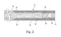
- FIG. 2is a side view of an exemplary embodiment of a reflectivity sensor of the presently disclosed system
- FIG. 3is a representation of various components of an exemplary embodiment of an imaging module of the presently disclosed system
- FIG. 4is a graph of reflectance versus wavelength data for various lesion and de novo tissue samples
- FIG. 5is a graph showing an amount of light reflected in various 40 nm wavebands centered at 500 nm, 550 nm, 560 nm, 600 nm, and 650 nm;
- FIG. 6is a representative view of a treatment site from along a longitudinal axis of a catheter
- FIG. 7is a schematic representation of an exemplary embodiment of an ablation catheter positioned adjacent an ostium of a pulmonary vein
- FIG. 8Ais a side view of an embodiment of an ablation catheter showing a reflectivity sensor and an energy emitter disposed therein;
- FIG. 8Bis a top view of the embodiment of FIG. 8A ;
- FIG. 9Ais a representation of various target regions capable of being targeted by an embodiment of an energy emitter slidably disposed within an ablation catheter;
- FIG. 9Bis a schematic representation of overlapping lesions encircling an ostium of a pulmonary vein.
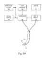
- FIG. 10is a representation of an embodiment of a visualization system incorporated into a cardiac ablation system.
- the systemscan also provide real-time video imaging of the cardiac treatment site indicative of treated and untreated tissue regions.
- the systemcan be utilized in treating atrial fibrillation where a plurality of partial or complete ring-like or “spot” tissue regions extending along various portions of an ostium of a pulmonary vein are ablated to provide a continuous lesions surrounding the vein.
- the systemscan determine which regions have been treated, which regions have not been treated, which regions have been treated but are in need of further treatment, etc.
- the various embodiments of the visualization and imaging systemscan be incorporated into and/or used in conjunction with an ablation catheter configured to specifically target and ablate a region in need of treatment.
- FIG. 1provides a general representation of the presently disclosed visualization and imaging system 10 .
- the system 10typically includes an illumination source 11 configured to irradiate at least a portion of a tissue area with light, and a reflectivity sensor 12 configured to detect resulting absorbance/reflectivity data.
- the system 10also includes an imaging module 16 in communication with the reflectivity sensor 12 , and configured to generate a plurality of images which, taken together, can distinguish lesions from untreated, de novo tissue. That is, the imaging module 16 can be specifically tuned to those wavebands which exhibit subtle differences between treated and untreated tissue.
- the reflectivity sensor 12can play a role in detecting and/or transmitting reflectivity/absorbance data from the reflected light to the imaging module 16 .
- the reflectivity sensor 12 , illumination source 11 , and the imaging module 16can be considered to be components in a visualization module 26 of the system 10 .
- the system 10can further include a processor 18 configured to receive data from the imaging module 16 , compare such absorbance/reflectivity data of various wavebands, and utilize these comparisons as well as various other levels of analysis for the purpose of classifying the area as lesion or de novo tissue.
- the processor 18can also generate a combined image of the tissue by combining a plurality of waveband specific images generated by the imaging module 16 . Additionally, the processor 18 can apply some degree of false-coloring (e.g., coloring, shading, brightening, etc.) indicative of treatment status (e.g., lesion or de novo) to the combined image.
- the system 10can also include a video monitor 20 configured to provide a real-time view of the combined image as generated by the processor 18 . Thus, the system 10 can provide real-time information indicative of lesions and identifying those areas in need of treatment.
- the system 10can also include various other optional components.
- the system 10can include a mechanism 13 for providing heparinized saline irrigation for a sheath of an endoscopic ablation catheter system (discussed further below), a laser console 15 for generating ablation energy, a cooling console 17 , and/or a syringe 19 for delivering fluid (e.g., D 2 O) to an inflation balloon of the catheter system.
- fluide.g., D 2 O
- the reflectivity sensor 12can be any component which is sized and shaped so as to be delivered to a treatment site (e.g., via a cardiac catheter) and further configured to detect light reflected by the target tissue site, and also configured to transit reflectivity/absorbance data to the imaging module 16 .
- the reflectivity sensoris a fiber-optic endoscope.
- FIG. 2shows an exemplary embodiment of the fiber-optic endoscope with enhanced field of view.
- the endoscope 12includes a fiber bundle 30 within a protective polyimide tube 32 coupled to distal stainless steel tube 34 in which the field-enhancing optics are disposed.
- an imaging lens 36Within the distal tube 34 , an imaging lens 36 , and an objective lens 40 are situated, together with a centering and connecting tubes (e.g., tubes 35 , 42 ) as may be needed to secure the lenses 36 , 40 in place.
- a centering and connecting tubese.g., tubes 35 , 42
- the endoscope 12can have a wide field of view even while it is immersed in liquid.
- the endoscope 12will typically be immersed in either physiological saline (as is typically found in the inner lumen of a catheter) or deuterium oxide which is one preferred medium for filling a projection balloon (detailed below) coupled to a catheter. Both of these liquids have essentially the same index of refraction.
- the lens systemcan be configured to provide the desired field of view in such liquid environments. That is, the lens system includes two plano-convex lenses 36 , 38 arranged as shown along with an apertured window 44 .
- High index of refraction materialsare preferably used for the lenses 36 , 38 . Suitable materials include sapphire, cubic zirconia, or high index glass materials. All these materials are readily available as small diameter spheres with optical quality surfaces. The spheres can be made into hemispheres and the diameter of the hemispheres are reduced using common lens grinding technology.
- the aperturecan be constructed by metalizing one surface of flat glass plate. The central aperture hole is created by masking the flat glass before the metallization or removing the metallization with a laser.
- the lens elementscan be formed of various materials and/or can have various dimensions.
- sample specifications for the lens elementsare as follows:
- the lens systemcan be configured to have a field of view of slightly larger than about 110° when immersed in water, an f number of about 2.5, and a depth of field that provides acceptable focus over a range of object distances from about 13 mm to about 40 mm.
- Acceptable focusis that degree of focus that results in minimum resolvable spot diameters that are close in size to about 5 microns, which is the size of the individual fibers in the image bundle of the endoscope.
- the lens elementscan be assembled so the spherical surfaces touch and therefore the elements are self-locating when assembled in a small lens cell tube 38 with an inner diameter just slightly larger than the outer diameter of the lens elements.
- the general assemblycan use precise diameter tubes of polyimide whose dimensions can be controlled very precisely and whose wall thicknesses can be made very thin.
- the ability have a field of view greater than about 50 degrees (and, preferably, in some applications, greater than about 70 degrees, or about 90 degrees)can be beneficial because of the geometry of the heart and the ablation elements capable of being utilized in combination with the reflectivity sensor 12 .
- visualization of an ostium of a pulmonary vein through a transparent liquid filled balloontypically requires a wide field of view.
- an energy element and/or various expandable balloon components of an ablation catheter, detailed belowmust be short due to the limited space available within the atrial chamber.
- the system 10also includes an imaging module 16 in communication with the reflectivity sensor 12 , and configured to receive absorbance and/or reflectivity signals/data from the sensor 12 .
- the imaging module 16can be specifically tuned to detect amounts of light reflected by the tissue at a plurality of predetermined wavebands which are selected due to their ability to distinguish between a lesion and de novo tissue. Additionally, the imaging module 16 can be configured to generate a plurality of images based on these plurality of predetermined wavebands. These images are then assembled into a combined image by a processor, detailed below, so as to provide a real time view of the treatment site with indications as to which tissue areas are lesions and which areas are in need of further treatment.
- FIG. 3is a schematic representation of various components of an exemplary embodiment of the imaging module 16 .
- the imaging module 16includes an image forming optics component 50 which is configured to receive reflectivity/absorbance data from the reflectivity sensor 12 , as represented by an arrow between these components 12 , 50 , and transmit the data into an image splitter 52 .
- the image splitter 50can split the image into any number of images as desired.
- the image module 16further includes a plurality of video chips 54 , 56 , 58 for generating a corresponding number of individual images which can later be combined by a processor of the system (detailed below).
- the image splitter 52will split the image into a number of images corresponding to the number of video chips.
- the image splitter 52splits the image into first, second, and third images directed towards first, second, and third video chips 54 , 56 , 58 , respectively.
- any number and/or type of video chipsare within the spirit and scope of the present disclosure.
- At least two of the video chips 54 , 56are specifically tailored towards specific wavebands such that an amount of light reflected at first and second wavebands can be compared relative to one another. As detailed below, the wavebands can be selected such that this comparison can indicate whether or not the target area is lesion or de novo tissue.
- the video chips 54 , 56 , 58can be tailored towards specific predetermined wavebands in various manners.
- each chip 54 , 56 , 58can be in communication with a distinct bandpass filter 60 , 62 , 64 with each filter 60 , 62 , 64 being tailored to a specific waveband of a certain width and centered at a specific wavelength.
- filters 60 , 62 , and 64are within the spirit and scope of the present disclosure.
- At least two video chipsfor example, the first and second video chips 54 , 56 , can be tailored towards first and second predetermined wavebands, respectively, with the resulting data indicative of whether the tissue area is a lesion or de novo tissue.
- the predetermined wavebandscan be determined by careful inspection of experimental absorbance/reflectivity data.
- FIG. 4provides several visible light spectra collected for untreated tissue (black lines) and lesions (gray lines). Inspection of these spectra revealed various characteristics of lesions and untreated tissue.
- the general shape of the spectraare similar for both lesion and untreated tissue. That is, both lesion and untreated tissue reflect light readily in the waveband of about 425 nm to about 500 nm, and also readily reflect light in the waveband of about 623 nm to the infrared region beyond about 700 nm. Both lesion and tissue absorb light in the range of about 525 nm to about 575 nm.
- This general similarity in the shape of the spectraaccounts for the similar appearance of lesion and untreated tissue when viewed with standard video equipment. However, closer inspection of the spectra reveals that lesion spectra exhibit two absorption valleys at about 540 nm and at about 576 nm, and untreated tissue spectra exhibit a single absorption valley at about 555 nm.
- the image module 16can be configured to analyze spectra data for tissue to determine for any given spectra, how much light there is in any specific waveband.
- FIG. 5provides a representation of the relative amount of light in each of four 40 nm wide wavebands centered at 500 nm, 550 nm, 560 nm, and 600 nm for each of the spectra provided in FIG. 4 . Forty nm wide wavebands were selected because they are wide enough to collect an adequate amount of light to create an image while still being narrow enough to pick out subtle distinctions between the lesion and de novo tissue spectra. Those skilled in the art will appreciate that filters of various other bandpass widths are within the spirit and scope of the present disclosure. As shown in FIG.
- the amount of light in the waveband centered at about 550 nmis less than the waveband centered at about 560 nm. Conversely, for all the untreated (de novo) tissue spectra, the amount of light in the waveband centered at about 550 nm is greater that that in the waveband centered at about 560 nm.
- the chips 54 , 56 and corresponding bandpass filters 60 , 62can be configured to distinguish lesions from de novo tissue. That is, the system can include a first chip 54 in communication with a first bandpass filter 60 which is a 40 nm wide filter centered at about 550 nm, and a second chip 56 in communication with a second bandpass filter 62 which is a 40 nm wide filter centered at about 560 nm.
- the systemcan also include a third chip 59 in communication with a third filter 64 wherein the third filter 64 can be some other desired waveband, e.g., either in the blue band or in the red band.
- This third filter 64provides a third color channel to create an image with more or less natural color, and may not necessarily serve a role in distinguishing lesion from untreated tissue.
- a red color bandis preferred as a third bandpass filter 64 as such a filter would allow facilitate viewing blood.
- the system 10can also include a processor 18 in communication with the imaging module 16 . More specifically, the processor 18 can be configured to combine images from each of the individual video chips 54 , 56 , 58 into a single, more or less natural color combined image. The processor 18 can also be configured to determine whether a target tissue is a lesion or untreated tissue by comparing the light absorbed/reflected by the tissue at a first, predetermined waveband as compared to light absorbed/reflected by the tissue at a second, predetermined waveband.
- the processor 18can be configured to compare an amount of light reflected within the 550 nm waveband (as imaged by the first chip 54 ) to the amount of light reflected within the 560 nm waveband for each pixel of the combined image. If the 560 nm band exceeds the 550 nm band, the software can indentify the pixel as a lesion, and the software can apply some false coloring to the pixel. That is, the software can alter the data for this pixel in some manner so that in the combined image, displayed on a video monitor 20 of the system 10 , the pixel can be highlighted.
- Highlightingi.e., false coloring
- Highlightingcan take the form of increasing or decreasing the brightness of pixels identified as lesion or drawing contrasting borders around all pixels identified as lesion. Conversely, if the 550 nm band exceeds the 560 nm band, the software can indentify the pixel as untreated, de novo tissue.
- FIG. 6provides an example of a combined image generated by the processor 18 and displayed on a video monitor 20 .
- the video monitor 20can be configured to receive data from the processor 18 so as to provide a real-time image of the treatment site during ablation.
- the various components/modules of the systemprovide an image from the perspective of inside an ablation catheter, and looking along a longitudinal axis of catheter, and into a pulmonary vein. As shown, the image provides a user with a clear view of various target areas (e.g., partial ring-like regions extending along portions of the ostium), and also provides false coloring indicative of the treatment status.
- target arease.g., partial ring-like regions extending along portions of the ostium
- the imageindicates 6 partial ring-like target areas with these substantially over-lapping rings providing a circular lesion about the ostium of the pulmonary vein.
- the cliniciancan immediately identify and distinguish between those areas which have been treated and those areas in need of ablation.
- the above-described visualization and detection systemscan be introduced to the treatment site in various manners.
- various components of the systemcan be incorporated into and/or used in conjunction with a catheter (e.g., a cardiac ablation catheter).
- the cathetercan be any device configured to provide access to the treatment site (e.g., the ostium of the pulmonary vein).
- the catheterwill have proximal and distal ends with at least one lumen extending therebetween.
- the lumen(s)can be configured to allow for delivery of various instruments into communication with the target site.
- a reflectivity sensoras described above, can be sized and configured so as to be slidably disposed within a lumen of the catheter thereby allowing the sensor to be positioned at any location along the length of the catheter so as to facilitate irradiating the target site.
- an energy emittercan be slidably disposed within the lumen so as to deliver ablation energy to various target regions depending at least in part on the linear position of the ablation element relative to the catheter.
- FIG. 7provides an exemplary embodiment of an ablation catheter instrument 68 positioned adjacent an ostium 100 of a pulmonary vein, and having an ablation/visualization system 72 slidably disposed therein.
- the instrument 68can include an elongate catheter 14 having an inflation balloon 76 coupled to the distal end of the catheter 14 , and, upon inflation, the balloon 76 can be configured to provide substantially constant contact points 102 between portions of the balloon 76 and a circumference of the ostium 100 of the pulmonary vein.
- this continuous circumferential ringprovides a target region by removing blood from the area between the balloon and the tissue.
- the visualization system 10can provide a clinician with a real time view of the contact area between the balloon 76 and the ostium 100 , as well as the treatment status of the various target sites (e.g., the partial rings shown in FIG. 6 ).
- the balloon 76can have a shape configured to facilitate the desired procedure.
- the balloon 76can have a tear-drop shape thereby facilitating against over-insertion of the balloon 76 into the pulmonary vein.
- the balloon 76can also be formed of various materials (including both compliant and non-compliant materials).
- Various embodiments of such balloonsare detailed in Applicants' co-pending patent applications U.S. Ser. No. 10/357,156, filed Feb. 3, 2003, U.S. Ser. No. 11/504,354, filed Aug. 15, 2006, and U.S. Ser. No. 10/865,558, filed Jun. 10, 2004, the entirety of each of these applications being incorporated herein by reference.
- FIGS. 8A and 8Balso provide an example of a cardiac ablation catheter 70 which includes both a reflectivity sensor 14 and an energy emitter 70 (i.e., an ablation/visualization system 72 ) disposed therein.
- the reflectivity sensor 14resides in a first lumen
- the energy emitter 70resides in a second lumen extending substantially parallel to the first lumen.
- the illumination sourcecan be disposed in yet another lumen of the catheter.
- Each the reflectivity sensor 14 and the energy emitter 70can be slidably disposed within their respective lumens thereby allowing each component 14 , 70 to be independently positioned at any location along the length of the catheter 70 .
- ablation proceduressuch as the treatment of atrial fibrillation
- the ability to independently position these elementsfacilitates treatment by allowing numerous regions to be treated and/or visualized without moving the catheter 70 .
- the energy emitter 74can be incorporated into the cardiac ablation catheter 68 .
- the energy emitter 74can be any element capable of delivering an amount, power, configuration, and/or shape (e.g., partial ring, complete ring, spot) of ablation energy to a target area.
- the radiant energy emitter 74can include at least one optical fiber 110 in communication with an optical element(s) 112 , 114 , which cooperate to deliver ablative light energy through the instrument 68 to the target site.
- the catheter body 14 , projection balloon 76 , and inflation/ablation fluids (if present)are all preferably substantially transparent to the radiant energy at the selected wavelength to provide a low-loss transmission pathway from the ablation element 74 to the target.
- FIGS. 9A and 9Billustrate an advantage of an independently positionable energy emitter 74 which is slidably disposed within a lumen of the catheter 70 . Because the radiant energy emitter does not require contact with a target tissue region and is, in fact, decoupled from the rest of the instrument 68 , the clinician is free to select a desired target region by simply moving the emitter 74 within and relative to the lumen of the catheter 70 . As shown in FIG. 9A , the radiant energy emitter 74 can be positioned to form a ring-like lesion at a particular location by positioning the radiant energy emitter 74 at the rear of the projection balloon 76 —at a distance from the target tissue denoted as “C”.
- a smaller ring-like lesioncan be formed by positioning the radiant energy emitter 74 closer to the front of the projection balloon 76 , as shown in positions “A” or “B”. Smaller lesions can be preferably when the geometer of the vein ostium presents a sharper change in diameter. Also, it may be desirable to change the intensity of the emitted radiation depending upon the distance it must be projected. For example, a more intense radiant energy beam may be desirable in the scheme illustrated in position “C” in comparison with position “A”.
- the geometries of the pulmonary veinmay be such that no single annular lesion can form a continuous conduction block.
- the present inventionprovides a mechanism for addressing this problem by adjustment of the location of the energy emitter to form two or more partially circumferential lesions.
- the devices of the present inventioncan form a first lesion 130 and a second lesion 132 , each in the form of an arc or partial ring. Because each lesion has a thickness (dependent largely by the amount of energy deposited into the tissue) the two lesions can axially combine, as shown, to form a continuous encircling or circumscribing lesion that blocks conduction.
- some ablation proceduresrequire an energy emitter 74 configured to deliver partial rings and/or “spots” of ablative energy to any of a plurality of target regions. That is, in the case of treating atrial fibrillation, the energy emitter 74 can be configured to slide and rotate relative to the substantially stationary catheter 14 so as to deliver a plurality of partial ring-like or spot lesions to corresponding locations. This treatment can continue until each of the plurality of treatment regions has been targeted (i.e., ablated) thereby providing a continuous circumferential lesion surrounding the pulmonary vein which is essentially formed of a plurality of overlapping lesions.
- FIG. 10is a schematic block diagram illustrating the visualization/ablation instrument 68 comprising a reflectivity sensor 12 and ablation element 74 connected to an analyzer system.
- the analyzer systemcan include the imaging module 16 , discussed above, which can further be in communication with a display module 20 (via a processor, detailed above) for clinician viewing.
- the display 20can be a monitor or a heads-up projection onto glasses worn by members of the surgical team.
- the systemcan further include an energy source 144 , a controller 144 , and/or a user interface 142 .
- the illumination source(shown in FIG. 1 ) directs light to the target site and the reflectivity sensor 12 detects and transfers image data to/from the treatment to the image module 16 for processing by the imaging module 16 and/or controller 140 to determine whether a suitable ablation path can be created.
- the systemcan further include an aiming light source 146 which can also be used to visualize the location where energy will be delivered to the tissue. If a suitable ablation path is seen by the surgeon, the controller 140 can transmit radiant energy from the ablation element 74 to a target tissue site to effect ablation.
- the controller 140can further provide simulated displays to the user, superimposing, for example, a predicted lesion pattern on the image acquired by the imaging module 16 or superimposing dosimetry information based on the lesion location.
- the controller 140can further include a memory for storing and displaying data, such as pre-procedure images, lesion predictions and/or actual outcomes.
- the controller 140can further provide a safety shutoff to the system in the event that a clear transmission pathway between the radiant energy source and the target tissue is lost during energy delivery.
- a method for treating atrial fibrillationincludes selecting and/or identifying a plurality of partial ring-like tissue areas surrounding an ostium of a pulmonary vein. These ring-like tissue areas are selected such that, when taken together, the tissue areas form a substantially continuous lesion around the ostium. Thus, the tissue areas are typically over-lapping partial rings of tissue.
- the visualization systemallows a user to accurately identify the starting point and end point of a partial ring-like tissue lesion.
- the usercan begin a second lesion at the end point of a first lesion thereby providing a continuous circumferential lesion made up of a plurality of accurately and efficiently delivered partial lesions.
- the methodscan utilize various embodiments of the above-described visualization system to determine which if a particular area is already a lesion (i.e., from a prior treatment) or if the area is de novo tissue in need of treatment. That is, the method can include irradiating the area with light from a reflective sensor which is disposed within a cardiac catheter, and analyzing the reflectivity/absorbance data resulting from the irradiation by a imaging module. As detailed above, the imaging module can detect reflectivity data at at least two pre-determined wavebands (e.g., centered at about 550 nm and 560 nm, respectively) wherein a processor can compare this information to determine if the tissue is a lesion or de novo tissue. The clinician can then utilize this information (by viewing a real-time video monitor) to ablate de novo tissue and/or to prevent over-treatment of a lesion.
- the imaging modulecan detect reflectivity data at at least two pre-determined wavebands (e.g., centered
Landscapes
- Health & Medical Sciences (AREA)
- Life Sciences & Earth Sciences (AREA)
- Surgery (AREA)
- Physics & Mathematics (AREA)
- Engineering & Computer Science (AREA)
- Veterinary Medicine (AREA)
- Public Health (AREA)
- General Health & Medical Sciences (AREA)
- Biomedical Technology (AREA)
- Heart & Thoracic Surgery (AREA)
- Medical Informatics (AREA)
- Molecular Biology (AREA)
- Animal Behavior & Ethology (AREA)
- Biophysics (AREA)
- Pathology (AREA)
- Nuclear Medicine, Radiotherapy & Molecular Imaging (AREA)
- Radiology & Medical Imaging (AREA)
- Optics & Photonics (AREA)
- Artificial Intelligence (AREA)
- Electromagnetism (AREA)
- Otolaryngology (AREA)
- Spectroscopy & Molecular Physics (AREA)
- Evolutionary Computation (AREA)
- Fuzzy Systems (AREA)
- Mathematical Physics (AREA)
- Computer Vision & Pattern Recognition (AREA)
- Physiology (AREA)
- Psychiatry (AREA)
- Signal Processing (AREA)
- Cardiology (AREA)
- Surgical Instruments (AREA)
- Investigating Or Analysing Materials By Optical Means (AREA)
Abstract
Description
| TABLE 1 |
| Lens Specifications |
| Element | Spherical | Overall | Center | |
| Name | Material | Radius | Diameter | thickness |
| Object Lens | Cubic Zirconia | 0.200 mm | 0.400 mm | 0.244 mm |
| or high index | ||||
| glass | ||||
| Image Lens | Saphire or high | 0.300 mm | 0.400 mm | 0.187 mm |
| index glass | ||||
| Aperture | Schott B270 | Flat on both | 0.400 mm | 0.125 mm |
| Window | Grade A glass | Faces | ||
| 0.060 mm | ||||
| dia. | ||||
Claims (13)
Priority Applications (3)
| Application Number | Priority Date | Filing Date | Title |
|---|---|---|---|
| US12/423,137US8900219B2 (en) | 1999-07-14 | 2009-04-14 | System and method for visualizing tissue during ablation procedures |
| PCT/US2010/031032WO2010120881A2 (en) | 2009-04-14 | 2010-04-14 | System and method for visualizing tissue during ablation procedures |
| US14/530,002US9421066B2 (en) | 1999-07-14 | 2014-10-31 | System and method for visualizing tissue during ablation procedures |
Applications Claiming Priority (9)
| Application Number | Priority Date | Filing Date | Title |
|---|---|---|---|
| US09/357,355US6423055B1 (en) | 1999-07-14 | 1999-07-14 | Phototherapeutic wave guide apparatus |
| US09/602,420US6572609B1 (en) | 1999-07-14 | 2000-06-23 | Phototherapeutic waveguide apparatus |
| US09/616,275US6626900B1 (en) | 1999-07-14 | 2000-07-14 | Intralumenal contact sensor |
| US09/924,393US6676656B2 (en) | 1994-09-09 | 2001-08-07 | Surgical ablation with radiant energy |
| US10/357,156US8025661B2 (en) | 1994-09-09 | 2003-02-03 | Coaxial catheter instruments for ablation with radiant energy |
| US47737403P | 2003-06-10 | 2003-06-10 | |
| US10/674,114US6942657B2 (en) | 1999-07-14 | 2003-09-29 | Intralumenal contact sensor |
| US10/865,558US8540704B2 (en) | 1999-07-14 | 2004-06-10 | Guided cardiac ablation catheters |
| US12/423,137US8900219B2 (en) | 1999-07-14 | 2009-04-14 | System and method for visualizing tissue during ablation procedures |
Related Parent Applications (1)
| Application Number | Title | Priority Date | Filing Date |
|---|---|---|---|
| US10/865,558Continuation-In-PartUS8540704B2 (en) | 1999-07-14 | 2004-06-10 | Guided cardiac ablation catheters |
Related Child Applications (1)
| Application Number | Title | Priority Date | Filing Date |
|---|---|---|---|
| US14/530,002ContinuationUS9421066B2 (en) | 1999-07-14 | 2014-10-31 | System and method for visualizing tissue during ablation procedures |
Publications (2)
| Publication Number | Publication Date |
|---|---|
| US20090326320A1 US20090326320A1 (en) | 2009-12-31 |
| US8900219B2true US8900219B2 (en) | 2014-12-02 |
Family
ID=42983121
Family Applications (2)
| Application Number | Title | Priority Date | Filing Date |
|---|---|---|---|
| US12/423,137Expired - LifetimeUS8900219B2 (en) | 1999-07-14 | 2009-04-14 | System and method for visualizing tissue during ablation procedures |
| US14/530,002Expired - Fee RelatedUS9421066B2 (en) | 1999-07-14 | 2014-10-31 | System and method for visualizing tissue during ablation procedures |
Family Applications After (1)
| Application Number | Title | Priority Date | Filing Date |
|---|---|---|---|
| US14/530,002Expired - Fee RelatedUS9421066B2 (en) | 1999-07-14 | 2014-10-31 | System and method for visualizing tissue during ablation procedures |
Country Status (2)
| Country | Link |
|---|---|
| US (2) | US8900219B2 (en) |
| WO (1) | WO2010120881A2 (en) |
Cited By (17)
| Publication number | Priority date | Publication date | Assignee | Title |
|---|---|---|---|---|
| US20090270846A1 (en)* | 2005-10-25 | 2009-10-29 | Teiji Nakayama | Catheter, examination system and thrombus removing device |
| US9456752B2 (en) | 2013-03-14 | 2016-10-04 | Aperture Diagnostics Ltd. | Full-field three-dimensional surface measurement |
| US20170181701A1 (en)* | 2014-03-25 | 2017-06-29 | Briteseed Llc | Vessel detector and method of detection |
| US10076238B2 (en) | 2011-09-22 | 2018-09-18 | The George Washington University | Systems and methods for visualizing ablated tissue |
| US10143517B2 (en) | 2014-11-03 | 2018-12-04 | LuxCath, LLC | Systems and methods for assessment of contact quality |
| USD851245S1 (en) | 2017-04-14 | 2019-06-11 | Cardiofocus, Inc. | Compliant balloon |
| US10722301B2 (en) | 2014-11-03 | 2020-07-28 | The George Washington University | Systems and methods for lesion assessment |
| US10736512B2 (en) | 2011-09-22 | 2020-08-11 | The George Washington University | Systems and methods for visualizing ablated tissue |
| US10779904B2 (en) | 2015-07-19 | 2020-09-22 | 460Medical, Inc. | Systems and methods for lesion formation and assessment |
| US10820838B2 (en)* | 2015-02-19 | 2020-11-03 | Briteseed, Llc | System for determining vessel size using light absorption |
| US11153696B2 (en) | 2017-02-14 | 2021-10-19 | Virtual 3-D Technologies Corp. | Ear canal modeling using pattern projection |
| US11344365B2 (en) | 2016-01-05 | 2022-05-31 | Cardiofocus, Inc. | Ablation system with automated sweeping ablation energy element |
| US11389236B2 (en) | 2018-01-15 | 2022-07-19 | Cardiofocus, Inc. | Ablation system with automated ablation energy element |
| US11457817B2 (en) | 2013-11-20 | 2022-10-04 | The George Washington University | Systems and methods for hyperspectral analysis of cardiac tissue |
| US12076081B2 (en) | 2020-01-08 | 2024-09-03 | 460Medical, Inc. | Systems and methods for optical interrogation of ablation lesions |
| US12306426B2 (en) | 2021-08-27 | 2025-05-20 | Furukawa Electric Co., Ltd. | Radiation probe with radial scatter regions with various intensities |
| US12343114B2 (en) | 2013-11-14 | 2025-07-01 | The George Washington University | Systems and methods for determining lesion depth using fluorescence imaging |
Families Citing this family (32)
| Publication number | Priority date | Publication date | Assignee | Title |
|---|---|---|---|---|
| US8025661B2 (en) | 1994-09-09 | 2011-09-27 | Cardiofocus, Inc. | Coaxial catheter instruments for ablation with radiant energy |
| US9033961B2 (en) | 1999-07-14 | 2015-05-19 | Cardiofocus, Inc. | Cardiac ablation catheters for forming overlapping lesions |
| US8540704B2 (en) | 1999-07-14 | 2013-09-24 | Cardiofocus, Inc. | Guided cardiac ablation catheters |
| US7935108B2 (en) | 1999-07-14 | 2011-05-03 | Cardiofocus, Inc. | Deflectable sheath catheters |
| US8900219B2 (en) | 1999-07-14 | 2014-12-02 | Cardiofocus, Inc. | System and method for visualizing tissue during ablation procedures |
| US9795442B2 (en) | 2008-11-11 | 2017-10-24 | Shifamed Holdings, Llc | Ablation catheters |
| US8696653B2 (en)* | 2009-10-02 | 2014-04-15 | Cardiofocus, Inc. | Cardiac ablation system with pulsed aiming light |
| WO2011041638A2 (en)* | 2009-10-02 | 2011-04-07 | Cardiofocus, Inc. | Cardiac ablation system with automatic safety shut-off feature |
| US20110082450A1 (en)* | 2009-10-02 | 2011-04-07 | Cardiofocus, Inc. | Cardiac ablation system with inflatable member having multiple inflation settings |
| US8702688B2 (en)* | 2009-10-06 | 2014-04-22 | Cardiofocus, Inc. | Cardiac ablation image analysis system and process |
| US9655677B2 (en) | 2010-05-12 | 2017-05-23 | Shifamed Holdings, Llc | Ablation catheters including a balloon and electrodes |
| AU2011252976A1 (en) | 2010-05-12 | 2012-11-08 | Shifamed Holdings, Llc | Low profile electrode assembly |
| US9095715B2 (en)* | 2010-12-23 | 2015-08-04 | Medtronic, Inc. | Implanted device data to guide ablation therapy |
| US9061155B2 (en) | 2010-12-23 | 2015-06-23 | Medtronic, Inc. | Implanted device data to guide ablation therapy |
| US9668643B2 (en) | 2011-12-29 | 2017-06-06 | Cook Medical Technologies Llc | Space-optimized visualization catheter with oblong shape |
| US10244927B2 (en) | 2011-12-29 | 2019-04-02 | Cook Medical Technologies Llc | Space-optimized visualization catheter with camera train holder |
| EP2797490B1 (en) | 2011-12-29 | 2016-11-09 | Cook Medical Technologies LLC | Space-optimized visualization catheter having a camera train holder in a catheter with off-centered lumens |
| KR20150140760A (en) | 2013-04-08 | 2015-12-16 | 아파마 메디칼, 인크. | Cardiac ablation catheters and methods of use thereof |
| US10098694B2 (en) | 2013-04-08 | 2018-10-16 | Apama Medical, Inc. | Tissue ablation and monitoring thereof |
| US10349824B2 (en) | 2013-04-08 | 2019-07-16 | Apama Medical, Inc. | Tissue mapping and visualization systems |
| CN106028914B (en)* | 2013-11-14 | 2020-09-15 | 乔治华盛顿大学 | System and method for determining lesion depth using fluorescence imaging |
| EP3137007A4 (en)* | 2014-04-28 | 2017-09-27 | Cardiofocus, Inc. | System and method for visualizing tissue with an icg dye composition during ablation procedures |
| US10154888B2 (en)* | 2014-12-03 | 2018-12-18 | Cardiofocus, Inc. | System and method for visual confirmation of pulmonary vein isolation during abalation procedures |
| WO2016151111A1 (en)* | 2015-03-26 | 2016-09-29 | Koninklijke Philips N.V. | System and method for tumor ablation treatment planning including core tumor, margin and healthy tissue coverage |
| US11154186B2 (en) | 2015-07-31 | 2021-10-26 | University Of Utah Research Foundation | Devices, systems, and methods for imaging and treating a selected tissue |
| EP4302713A3 (en) | 2015-11-16 | 2024-03-13 | Boston Scientific Scimed, Inc. | Energy delivery devices |
| AU2017346947A1 (en)* | 2016-10-21 | 2019-05-23 | Lazcath Pty Ltd | Fibre optic assembly |
| US11602270B2 (en) | 2017-02-01 | 2023-03-14 | University Of Utah Research Foundation | Devices and methods for mapping cardiac tissue |
| RU179813U1 (en)* | 2017-07-13 | 2018-05-24 | Алексей Сергеевич Лисицын | PHOTOVIDEO-ENDOSCOPIC DEVICE |
| CN114981695B (en) | 2019-12-17 | 2024-11-12 | 犹他大学研究基金会 | Characterizing Cardiac Tissue Using Catheterized Light Scattering Spectroscopy |
| EP4243671A4 (en)* | 2020-11-12 | 2024-09-11 | Cardiofocus, Inc. | Ablation catheters with multiple endoscopes and imaging chip endoscopes and system for altering an orientation of an endoscopic image |
| WO2022169813A1 (en) | 2021-02-05 | 2022-08-11 | Cardiofocus, Inc. | Endoscopically guided ablation catheters with thermally resistant balloons |
Citations (219)
| Publication number | Priority date | Publication date | Assignee | Title |
|---|---|---|---|---|
| US3417745A (en) | 1963-08-23 | 1968-12-24 | Sheldon Edward Emanuel | Fiber endoscope provided with focusing means and electroluminescent means |
| US3821510A (en) | 1973-02-22 | 1974-06-28 | H Muncheryan | Hand held laser instrumentation device |
| US4224929A (en) | 1977-11-08 | 1980-09-30 | Olympus Optical Co., Ltd. | Endoscope with expansible cuff member and operation section |
| US4233493A (en) | 1974-05-21 | 1980-11-11 | Nath Guenther | Apparatus for applying intense light radiation to a limited area |
| US4273109A (en) | 1976-07-06 | 1981-06-16 | Cavitron Corporation | Fiber optic light delivery apparatus and medical instrument utilizing same |
| US4336809A (en) | 1980-03-17 | 1982-06-29 | Burleigh Instruments, Inc. | Human and animal tissue photoradiation system and method |
| US4445892A (en) | 1982-05-06 | 1984-05-01 | Laserscope, Inc. | Dual balloon catheter device |
| US4585298A (en) | 1982-08-26 | 1986-04-29 | Kei Mori | Photoradiator for radiating light |
| US4625724A (en) | 1984-07-25 | 1986-12-02 | Fuji Photo Optical Co., Ltd. | Laser vascular anastomosis apparatus |
| US4660925A (en) | 1985-04-29 | 1987-04-28 | Laser Therapeutics, Inc. | Apparatus for producing a cylindrical pattern of light and method of manufacture |
| US4701166A (en) | 1983-05-03 | 1987-10-20 | Catheter Technology Corp. | Valved two-way catheter |
| US4718417A (en) | 1985-03-22 | 1988-01-12 | Massachusetts Institute Of Technology | Visible fluorescence spectral diagnostic for laser angiosurgery |
| US4770653A (en) | 1987-06-25 | 1988-09-13 | Medilase, Inc. | Laser angioplasty |
| US4781681A (en) | 1987-09-15 | 1988-11-01 | Gv Medical, Inc. | Inflatable tip for laser catheterization |
| US4819632A (en) | 1986-05-19 | 1989-04-11 | Davies David H | Retrolasing catheter and method |
| EP0311458A2 (en) | 1987-10-08 | 1989-04-12 | The Beth Israel Hospital Association | Laser balloon catheter |
| US4842390A (en) | 1987-07-17 | 1989-06-27 | Consiglio Nazionale Delle Ricerche | Fiber optic device for angioplasty |
| US4852567A (en) | 1988-01-21 | 1989-08-01 | C. R. Bard, Inc. | Laser tipped catheter |
| US4860743A (en) | 1986-10-27 | 1989-08-29 | University Of Florida | Laser method and apparatus for the recanalization of vessels and the treatment of other cardiac conditions |
| US4862886A (en) | 1985-05-08 | 1989-09-05 | Summit Technology Inc. | Laser angioplasty |
| US4878725A (en) | 1987-05-25 | 1989-11-07 | Messerschmitt-Bolkow-Blohm Gmbh | Apparatus for the circumferential irradiation of objects |
| US4913142A (en) | 1985-03-22 | 1990-04-03 | Massachusetts Institute Of Technology | Catheter for laser angiosurgery |
| US4961738A (en) | 1987-01-28 | 1990-10-09 | Mackin Robert A | Angioplasty catheter with illumination and visualization within angioplasty balloon |
| US5026367A (en) | 1988-03-18 | 1991-06-25 | Cardiovascular Laser Systems, Inc. | Laser angioplasty catheter and a method for use thereof |
| US5030201A (en) | 1989-11-24 | 1991-07-09 | Aubrey Palestrant | Expandable atherectomy catheter device |
| US5053033A (en) | 1990-10-10 | 1991-10-01 | Boston Advanced Technologies, Inc. | Inhibition of restenosis by ultraviolet radiation |
| US5071417A (en) | 1990-06-15 | 1991-12-10 | Rare Earth Medical Lasers, Inc. | Laser fusion of biological materials |
| US5078681A (en) | 1989-10-23 | 1992-01-07 | Olympus Optical Co., Ltd. | Balloon catheter apparatus with releasable distal seal and method of operation |
| US5090959A (en) | 1987-04-30 | 1992-02-25 | Advanced Cardiovascular Systems, Inc. | Imaging balloon dilatation catheter |
| US5109859A (en) | 1989-10-04 | 1992-05-05 | Beth Israel Hospital Association | Ultrasound guided laser angioplasty |
| US5125925A (en) | 1988-08-03 | 1992-06-30 | Photoradiation Systems | Intracavity laser catheter with sensing fiber |
| US5133709A (en) | 1990-02-23 | 1992-07-28 | Prince Martin R | Optical fiber with atraumatic rounded end for use in laser angioplasty |
| US5140987A (en) | 1989-03-17 | 1992-08-25 | Wayne State University | Method for transvenous ablation of cardiac electrically conductive tissue by laser photocoagulation |
| EP0214712B1 (en) | 1985-07-31 | 1992-09-02 | C.R. Bard, Inc. | Infrared laser catheter apparatus |
| US5151097A (en) | 1989-09-01 | 1992-09-29 | S.L.T. Japan Co., Ltd. | Laser light emitter |
| US5151096A (en) | 1991-03-28 | 1992-09-29 | Angiolaz, Incorporated | Laser catheter diffuser |
| WO1992017243A3 (en) | 1991-04-05 | 1992-11-12 | Aria Corp | Apparatus using a laser lucent needle |
| US5163935A (en) | 1991-02-20 | 1992-11-17 | Reliant Laser Corporation | Surgical laser endoscopic focusing guide with an optical fiber link |
| US5169395A (en) | 1991-04-26 | 1992-12-08 | Pdt Cardiovascular, Inc. | Laser delivery system |
| US5188634A (en) | 1990-07-13 | 1993-02-23 | Trimedyne, Inc. | Rotatable laser probe with beveled tip |
| US5188632A (en) | 1984-12-07 | 1993-02-23 | Advanced Interventional Systems, Inc. | Guidance and delivery system for high-energy pulsed laser light |
| US5190538A (en) | 1991-04-22 | 1993-03-02 | Trimedyne, Inc. | Method and apparatus for subjecting a body site to a movable beam of laterally directed laser radiation |
| US5196005A (en) | 1991-11-26 | 1993-03-23 | Pdt Systems, Inc. | Continuous gradient cylindrical diffusion tip for optical fibers and method for making |
| WO1993006888A1 (en) | 1991-10-03 | 1993-04-15 | Deutsch Alan S | Device for laser surgery in narrow passages |
| US5207699A (en) | 1989-10-30 | 1993-05-04 | Coe Frederick L | Lancet handling and disposal assembly |
| US5209748A (en) | 1989-08-24 | 1993-05-11 | S.L.T. Japan Co., Ltd. | Laser light irradiation apparatus |
| US5219346A (en) | 1990-01-09 | 1993-06-15 | Ciba-Geigy Corporation | Light diffuser for the photodynamic therapy of tumors in the oesophagus of a patient |
| US5242438A (en) | 1991-04-22 | 1993-09-07 | Trimedyne, Inc. | Method and apparatus for treating a body site with laterally directed laser radiation |
| WO1993019680A1 (en) | 1992-04-06 | 1993-10-14 | Laser-Medizin-Zentrum Gmbh Berlin | Working shaft for photo-thermal therapy |
| US5261904A (en) | 1990-01-30 | 1993-11-16 | C. R. Bard, Inc. | Laser catheter having diffraction grating for beam shaping |
| US5269777A (en) | 1990-11-01 | 1993-12-14 | Pdt Systems, Inc. | Diffusion tip for optical fibers |
| WO1993025155A1 (en) | 1992-06-12 | 1993-12-23 | Pdt Systems | Cylindrical diffusion tips for optical fibers and method for making |
| USRE34544E (en) | 1982-11-23 | 1994-02-15 | The Beth Israel Hospital Association | Method of treatment of artherosclerosis and balloon catheter the same |
| EP0598984A1 (en) | 1992-07-06 | 1994-06-01 | CeramOptec GmbH | Radial medical laser delivery device |
| US5318024A (en) | 1985-03-22 | 1994-06-07 | Massachusetts Institute Of Technology | Laser endoscope for spectroscopic imaging |
| WO1994017434A1 (en) | 1993-01-21 | 1994-08-04 | Fiberguide Industries, Inc. | Fiber optic cylindrical diffuser |
| US5350375A (en) | 1993-03-15 | 1994-09-27 | Yale University | Methods for laser induced fluorescence intensity feedback control during laser angioplasty |
| US5363458A (en) | 1994-02-28 | 1994-11-08 | Fiber Guide Industries | Fiber optic light diffuser |
| WO1994026184A1 (en) | 1993-05-14 | 1994-11-24 | Laser-Medizin-Zentrum Gmbh, Berlin | Process and device for thermally obliterating biological tissues |
| US5368564A (en) | 1992-12-23 | 1994-11-29 | Angeion Corporation | Steerable catheter |
| EP0292621B1 (en) | 1987-05-26 | 1994-12-14 | Surgical Laser Technologies, Inc. | Contact or insertion laser probe having wide angle radiation |
| US5374953A (en)* | 1991-02-01 | 1994-12-20 | Olympus Optical Co., Ltd. | Electronic endoscope apparatus with signal validity monitor |
| US5380316A (en) | 1990-12-18 | 1995-01-10 | Advanced Cardiovascular Systems, Inc. | Method for intra-operative myocardial device revascularization |
| US5380317A (en) | 1988-06-10 | 1995-01-10 | Trimedyne Laser Systems, Inc. | Medical device applying localized high intensity light and heat, particularly for destruction of the endometrium |
| EP0437181B1 (en) | 1990-01-09 | 1995-01-18 | Ciba-Geigy Ag | Apparatus for irradiating the bronchia of a patient for a photodynamic therapy |
| US5395362A (en) | 1992-01-14 | 1995-03-07 | Summit Technology | Methods and apparatus for distributing laser radiation |
| US5401270A (en) | 1990-12-19 | 1995-03-28 | Carl-Zeiss-Stiftung | Applicator device for laser radiation |
| US5409483A (en)* | 1993-01-22 | 1995-04-25 | Jeffrey H. Reese | Direct visualization surgical probe |
| US5417653A (en) | 1993-01-21 | 1995-05-23 | Sahota; Harvinder | Method for minimizing restenosis |
| US5418649A (en) | 1992-04-28 | 1995-05-23 | Olympus Optical Co., Ltd. | Objective lens system for endoscopes |
| US5423805A (en) | 1992-02-05 | 1995-06-13 | Angeion Corporation | Laser catheter with moveable integral fixation wires |
| US5427119A (en) | 1993-11-03 | 1995-06-27 | Daig Corporation | Guiding introducer for right atrium |
| US5431647A (en) | 1994-07-13 | 1995-07-11 | Pioneer Optics Company | Fiberoptic cylindrical diffuser |
| US5437660A (en) | 1991-12-30 | 1995-08-01 | Trimedyne, Inc. | Tissue ablation and a lateral-lasing fiber optic device therefor |
| US5441497A (en) | 1994-07-14 | 1995-08-15 | Pdt Cardiovascular, Inc. | Light diffusing guidewire |
| US5445608A (en) | 1993-08-16 | 1995-08-29 | James C. Chen | Method and apparatus for providing light-activated therapy |
| US5464404A (en) | 1993-09-20 | 1995-11-07 | Abela Laser Systems, Inc. | Cardiac ablation catheters and method |
| US5482037A (en) | 1993-01-18 | 1996-01-09 | X-Trode S.R.L. | Electrode catheter for mapping and operating on cardiac cavities |
| US5496305A (en) | 1985-03-22 | 1996-03-05 | Massachusetts Institue Of Technology | Catheter for laser angiosurgery |
| US5497774A (en) | 1993-11-03 | 1996-03-12 | Daig Corporation | Guiding introducer for left atrium |
| WO1996007451A3 (en) | 1994-09-09 | 1996-05-23 | Rare Earth Med Inc | Phototherapeutic apparatus |
| US5531664A (en) | 1990-12-26 | 1996-07-02 | Olympus Optical Co., Ltd. | Bending actuator having a coil sheath with a fixed distal end and a free proximal end |
| US5536265A (en) | 1994-03-25 | 1996-07-16 | Ciba-Geigy Corporation | Light diffuser and process for the manufacturing of a light diffuser |
| WO1996034646A1 (en) | 1995-05-01 | 1996-11-07 | Medtronic Cardiorhythm | Dual curve ablation catheter and method |
| US5575766A (en) | 1993-11-03 | 1996-11-19 | Daig Corporation | Process for the nonsurgical mapping and treatment of atrial arrhythmia using catheters guided by shaped guiding introducers |
| WO1996040342A1 (en) | 1995-06-07 | 1996-12-19 | Cardima, Inc. | Guiding catheter for coronary sinus |
| US5605162A (en) | 1991-10-15 | 1997-02-25 | Advanced Cardiovascular Systems, Inc. | Method for using a variable stiffness guidewire |
| US5613965A (en) | 1994-12-08 | 1997-03-25 | Summit Technology Inc. | Corneal reprofiling using an annular beam of ablative radiation |
| US5643253A (en) | 1995-06-06 | 1997-07-01 | Rare Earth Medical, Inc. | Phototherapy apparatus with integral stopper device |
| US5649923A (en) | 1988-10-24 | 1997-07-22 | The General Hospital Corporation | Catheter devices for delivering laser energy |
| US5662712A (en) | 1993-04-28 | 1997-09-02 | Focal, Inc. | Apparatus for intraluminal photothermoforming |
| WO1997037714A1 (en) | 1996-04-05 | 1997-10-16 | Medtronic, Inc. | Catheter with autoinflating, autoregulating balloon |
| US5680860A (en) | 1994-07-07 | 1997-10-28 | Cardiac Pathways Corporation | Mapping and/or ablation catheter with coilable distal extremity and method for using same |
| US5690611A (en) | 1994-07-08 | 1997-11-25 | Daig Corporation | Process for the treatment of atrial arrhythima using a catheter guided by shaped giding introducers |
| US5693043A (en) | 1985-03-22 | 1997-12-02 | Massachusetts Institute Of Technology | Catheter for laser angiosurgery |
| US5700243A (en) | 1992-10-30 | 1997-12-23 | Pdt Systems, Inc. | Balloon perfusion catheter |
| US5702438A (en) | 1995-06-08 | 1997-12-30 | Avitall; Boaz | Expandable recording and ablation catheter system |
| US5722401A (en) | 1994-10-19 | 1998-03-03 | Cardiac Pathways Corporation | Endocardial mapping and/or ablation catheter probe |
| US5725522A (en) | 1990-06-15 | 1998-03-10 | Rare Earth Medical, Inc. | Laser suturing of biological materials |
| US5759619A (en) | 1995-12-29 | 1998-06-02 | Lg Electronics Inc. | Method of manufacturing second harmonic generation device |
| US5769843A (en) | 1996-02-20 | 1998-06-23 | Cormedica | Percutaneous endomyocardial revascularization |
| US5773835A (en) | 1996-06-07 | 1998-06-30 | Rare Earth Medical, Inc. | Fiber optic spectroscopy |
| US5772590A (en) | 1992-06-30 | 1998-06-30 | Cordis Webster, Inc. | Cardiovascular catheter with laterally stable basket-shaped electrode array with puller wire |
| US5779646A (en) | 1995-02-28 | 1998-07-14 | E.P. Technologies Inc. | Deflectable biopsy catheter |
| US5782239A (en) | 1992-06-30 | 1998-07-21 | Cordis Webster, Inc. | Unique electrode configurations for cardiovascular electrode catheter with built-in deflection method and central puller wire |
| US5782899A (en) | 1992-06-05 | 1998-07-21 | Cardiac Pathways Corporation | Endocardial mapping and ablation system utilizing a separately controlled ablation catheter and method |
| US5800482A (en) | 1996-03-06 | 1998-09-01 | Cardiac Pathways Corporation | Apparatus and method for linear lesion ablation |
| US5807395A (en) | 1993-08-27 | 1998-09-15 | Medtronic, Inc. | Method and apparatus for RF ablation and hyperthermia |
| US5823955A (en) | 1995-11-20 | 1998-10-20 | Medtronic Cardiorhythm | Atrioventricular valve tissue ablation catheter and method |
| US5824005A (en) | 1995-08-22 | 1998-10-20 | Board Of Regents, The University Of Texas System | Maneuverable electrophysiology catheter for percutaneous or intraoperative ablation of cardiac arrhythmias |
| US5830209A (en) | 1992-02-05 | 1998-11-03 | Angeion Corporation | Multi-fiber laser catheter |
| US5833682A (en) | 1996-08-26 | 1998-11-10 | Illumenex Corporation | Light delivery system with blood flushing capability |
| US5845646A (en) | 1996-11-05 | 1998-12-08 | Lemelson; Jerome | System and method for treating select tissue in a living being |
| US5860974A (en) | 1993-07-01 | 1999-01-19 | Boston Scientific Corporation | Heart ablation catheter with expandable electrode and method of coupling energy to an electrode on a catheter shaft |
| US5885278A (en) | 1994-10-07 | 1999-03-23 | E.P. Technologies, Inc. | Structures for deploying movable electrode elements |
| US5891133A (en) | 1996-03-29 | 1999-04-06 | Eclipse Surgical Technologies, Inc. | Apparatus for laser-assisted intra-coronary transmyocardial revascularization and other applications |
| US5891134A (en) | 1996-09-24 | 1999-04-06 | Goble; Colin | System and method for applying thermal energy to tissue |
| US5904651A (en) | 1996-10-28 | 1999-05-18 | Ep Technologies, Inc. | Systems and methods for visualizing tissue during diagnostic or therapeutic procedures |
| US5908415A (en) | 1994-09-09 | 1999-06-01 | Rare Earth Medical, Inc. | Phototherapy methods and apparatus |
| US5931834A (en) | 1996-10-15 | 1999-08-03 | Eclipse Surgical Technologies, Inc. | Method for non-synchronous laser-assisted myocardial revascularization |
| US5938660A (en) | 1997-06-27 | 1999-08-17 | Daig Corporation | Process and device for the treatment of atrial arrhythmia |
| US5947959A (en) | 1994-09-09 | 1999-09-07 | Rare Earth Medical, Inc. | Phototherapeutic apparatus with diffusive tip assembly |
| US5967984A (en) | 1995-06-30 | 1999-10-19 | Boston Scientific Corporation | Ultrasound imaging catheter with a cutting element |
| US5971983A (en) | 1997-05-09 | 1999-10-26 | The Regents Of The University Of California | Tissue ablation device and method of use |
| US5995875A (en) | 1997-10-01 | 1999-11-30 | United States Surgical | Apparatus for thermal treatment of tissue |
| US6004269A (en) | 1993-07-01 | 1999-12-21 | Boston Scientific Corporation | Catheters for imaging, sensing electrical potentials, and ablating tissue |
| US6012457A (en) | 1997-07-08 | 2000-01-11 | The Regents Of The University Of California | Device and method for forming a circumferential conduction block in a pulmonary vein |
| US6024740A (en) | 1997-07-08 | 2000-02-15 | The Regents Of The University Of California | Circumferential ablation device assembly |
| US6056744A (en) | 1994-06-24 | 2000-05-02 | Conway Stuart Medical, Inc. | Sphincter treatment apparatus |
| US6064902A (en) | 1998-04-16 | 2000-05-16 | C.R. Bard, Inc. | Pulmonary vein ablation catheter |
| US6071281A (en) | 1998-05-05 | 2000-06-06 | Ep Technologies, Inc. | Surgical method and apparatus for positioning a diagnostic or therapeutic element within the body and remote power control unit for use with same |
| US6071279A (en) | 1996-12-19 | 2000-06-06 | Ep Technologies, Inc. | Branched structures for supporting multiple electrode elements |
| US6071302A (en) | 1997-12-31 | 2000-06-06 | Cardiofocus, Inc. | Phototherapeutic apparatus for wide-angle diffusion |
| US6086581A (en) | 1992-09-29 | 2000-07-11 | Ep Technologies, Inc. | Large surface cardiac ablation catheter that assumes a low profile during introduction into the heart |
| US6090084A (en) | 1994-07-08 | 2000-07-18 | Daig Corporation | Shaped guiding introducers for use with a catheter for the treatment of atrial arrhythmia |
| US6099514A (en) | 1996-08-13 | 2000-08-08 | Oratec Interventions, Inc. | Method and apparatus for delivering or removing material from the interior of an intervertebral disc |
| US6102905A (en) | 1994-09-09 | 2000-08-15 | Cardiofocus, Inc. | Phototherapy device including housing for an optical element and method of making |
| US6117071A (en) | 1997-07-29 | 2000-09-12 | Asahi Kogaku Kogyo Kabushiki Kaisha | Endoscope with movable imaging unit for zooming or focusing |
| US6117101A (en) | 1997-07-08 | 2000-09-12 | The Regents Of The University Of California | Circumferential ablation device assembly |
| US6120496A (en) | 1998-05-05 | 2000-09-19 | Scimed Life Systems, Inc. | Surgical method and apparatus for positioning a diagnostic or therapeutic element within the body and coupling device for use with same |
| US6146379A (en) | 1993-10-15 | 2000-11-14 | Ep Technologies, Inc. | Systems and methods for creating curvilinear lesions in body tissue |
| WO2000067656A1 (en) | 1999-05-11 | 2000-11-16 | Atrionix, Inc. | Tissue ablation device assembly and method for electrically isolating a pulmonary vein ostium from an atrial wall |
| US6159203A (en) | 1985-07-31 | 2000-12-12 | Cardiofocus, Inc. | Infrared laser catheter system |
| US6161543A (en) | 1993-02-22 | 2000-12-19 | Epicor, Inc. | Methods of epicardial ablation for creating a lesion around the pulmonary veins |
| US6164283A (en) | 1997-07-08 | 2000-12-26 | The Regents Of The University Of California | Device and method for forming a circumferential conduction block in a pulmonary vein |
| WO2001003599A2 (en) | 1999-07-14 | 2001-01-18 | Cardiofocus, Inc. | Photoablation system |
| US6179835B1 (en) | 1996-01-19 | 2001-01-30 | Ep Technologies, Inc. | Expandable-collapsible electrode structures made of electrically conductive material |
| WO2001013812A1 (en) | 1999-08-25 | 2001-03-01 | Cardiofocus, Inc. | Maneuverable optical fiber device for cardiac photoablation |
| US6217510B1 (en) | 1997-10-02 | 2001-04-17 | Olympus Optical Co., Ltd. | Endoscopes and endoscope devices which image regular observation images and fluorescent images as well as which provide easier operation of treatment tools |
| US6237605B1 (en) | 1996-10-22 | 2001-05-29 | Epicor, Inc. | Methods of epicardial ablation |
| US6240231B1 (en) | 1997-12-22 | 2001-05-29 | Micrus Corporation | Variable stiffness fiber optic shaft |
| US6245064B1 (en) | 1997-07-08 | 2001-06-12 | Atrionix, Inc. | Circumferential ablation device assembly |
| US6251109B1 (en) | 1997-06-27 | 2001-06-26 | Daig Corporation | Process and device for the treatment of atrial arrhythmia |
| US6251092B1 (en) | 1997-12-30 | 2001-06-26 | Medtronic, Inc. | Deflectable guiding catheter |
| WO2000067832A3 (en) | 1999-05-11 | 2001-07-05 | Atrionix Inc | Balloon anchor wire |
| US6270492B1 (en) | 1994-09-09 | 2001-08-07 | Cardiofocus, Inc. | Phototherapeutic apparatus with diffusive tip assembly |
| US20010030107A1 (en) | 2000-01-03 | 2001-10-18 | Peter Simpson | Auger lock |
| US6312427B1 (en) | 1998-10-23 | 2001-11-06 | Afx, Inc. | Directional reflector shield assembly for a microwave ablation instrument |
| US6314962B1 (en) | 1996-10-22 | 2001-11-13 | Epicor, Inc. | Method of ablating tissue around the pulmonary veins |
| US6325797B1 (en) | 1999-04-05 | 2001-12-04 | Medtronic, Inc. | Ablation catheter and method for isolating a pulmonary vein |
| US20020019627A1 (en) | 2000-06-13 | 2002-02-14 | Maguire Mark A. | Surgical ablation probe for forming a circumferential lesion |
| US6352531B1 (en) | 1999-03-24 | 2002-03-05 | Micrus Corporation | Variable stiffness optical fiber shaft |
| US20020029062A1 (en) | 2000-09-07 | 2002-03-07 | Shutaro Satake | Balloon catheter for pulmonary vein isolation |
| WO2001064123A3 (en) | 2000-02-29 | 2002-03-21 | Univ Johns Hopkins | Circumferential pulmonary vein ablation using a laser and fiberoptic balloon catheter |
| US6394949B1 (en) | 1998-10-05 | 2002-05-28 | Scimed Life Systems, Inc. | Large area thermal ablation |
| US20020065512A1 (en) | 2000-07-13 | 2002-05-30 | Todd Fjield | Thermal treatment methods and apparatus with focused energy application |
| US20020091383A1 (en) | 2000-04-27 | 2002-07-11 | Hooven Michael D. | Combination ablation and visualization apparatus for ablating cardiac tissue |
| US6423055B1 (en) | 1999-07-14 | 2002-07-23 | Cardiofocus, Inc. | Phototherapeutic wave guide apparatus |
| US6423058B1 (en) | 1998-02-19 | 2002-07-23 | Curon Medical, Inc. | Assemblies to visualize and treat sphincters and adjoining tissue regions |
| US20020107511A1 (en) | 2000-05-03 | 2002-08-08 | Collins Russell F. | Apparatus and methods for mapping and ablation in electrophysiology procedures |
| US6485485B1 (en) | 1998-08-13 | 2002-11-26 | Intraluminal Therapeutics, Inc. | Expandable laser catheter |
| US20020183739A1 (en) | 2001-03-30 | 2002-12-05 | Long Gary L. | Endoscopic ablation system with sealed sheath |
| US6500174B1 (en) | 1997-07-08 | 2002-12-31 | Atrionix, Inc. | Circumferential ablation device assembly and methods of use and manufacture providing an ablative circumferential band along an expandable member |
| US6514249B1 (en) | 1997-07-08 | 2003-02-04 | Atrionix, Inc. | Positioning system and method for orienting an ablation element within a pulmonary vein ostium |
| US6522933B2 (en) | 2001-03-30 | 2003-02-18 | Biosense, Webster, Inc. | Steerable catheter with a control handle having a pulley mechanism |
| US20030069620A1 (en) | 2001-10-09 | 2003-04-10 | Hong Li | Balloon catheters for non-continuous lesions |
| US6554794B1 (en) | 1997-09-24 | 2003-04-29 | Richard L. Mueller | Non-deforming deflectable multi-lumen catheter |
| US6558375B1 (en) | 2000-07-14 | 2003-05-06 | Cardiofocus, Inc. | Cardiac ablation instrument |
| US6562020B1 (en) | 1998-07-15 | 2003-05-13 | Corazon Technologies, Inc. | Kits for use in the treatment of vascular calcified lesions |
| US6579278B1 (en) | 2000-05-05 | 2003-06-17 | Scimed Life Systems, Inc. | Bi-directional steerable catheter with asymmetric fulcrum |
| US6579285B2 (en) | 1994-09-09 | 2003-06-17 | Cardiofocus, Inc. | Photoablation with infrared radiation |
| US6582536B2 (en) | 2000-04-24 | 2003-06-24 | Biotran Corporation Inc. | Process for producing steerable sheath catheters |
| US20030120270A1 (en) | 2001-04-23 | 2003-06-26 | Transurgical, Inc. | Ablation therapy |
| JP2003210028A (en) | 2002-01-23 | 2003-07-29 | Iseki & Co Ltd | Spiral spiral of zoom auger |
| US20030144657A1 (en) | 2002-01-28 | 2003-07-31 | Cardiac Pacemakers, Inc. | Inner and outer telescoping catheter delivery system |
| US6605055B1 (en) | 2000-09-13 | 2003-08-12 | Cardiofocus, Inc. | Balloon catheter with irrigation sheath |
| US6605084B2 (en) | 2000-03-24 | 2003-08-12 | Transurgical, Inc. | Apparatus and methods for intrabody thermal treatment |
| US20030158550A1 (en) | 1999-11-16 | 2003-08-21 | Ganz Robert A. | Method of treating abnormal tissue in the human esophagus |
| WO2002096479A3 (en) | 2001-05-31 | 2003-10-23 | Infraredx Inc | Balloon catheter |
| WO2003090835A1 (en) | 2002-04-25 | 2003-11-06 | Medtronic, Inc. | Improved system and method for positioning implantable medical devices within coronary veins |
| US6648875B2 (en) | 2001-05-04 | 2003-11-18 | Cardiac Pacemakers, Inc. | Means for maintaining tension on a steering tendon in a steerable catheter |
| US6669655B1 (en) | 1999-10-20 | 2003-12-30 | Transurgical, Inc. | Sonic element and catheter incorporating same |
| US20040006333A1 (en) | 1994-09-09 | 2004-01-08 | Cardiofocus, Inc. | Coaxial catheter instruments for ablation with radiant energy |
| US6676656B2 (en) | 1994-09-09 | 2004-01-13 | Cardiofocus, Inc. | Surgical ablation with radiant energy |
| US6679873B2 (en) | 1999-09-24 | 2004-01-20 | Omnisonics Medical Technologies, Inc. | Method for using a steerable catheter device |
| JP2004065076A (en) | 2002-08-05 | 2004-03-04 | Iseki & Co Ltd | Conveyor spiral of zoom auger |
| US6702780B1 (en) | 1999-09-08 | 2004-03-09 | Super Dimension Ltd. | Steering configuration for catheter with rigid distal device |
| US20040054360A1 (en) | 2002-09-17 | 2004-03-18 | Yitzhack Schwartz | Laser pulmonary vein isolation |
| US20040122290A1 (en) | 2001-03-30 | 2004-06-24 | Irion Klaus M. | Endoscopic visualization apparatus with different imaging systems |
| US6771996B2 (en) | 2001-05-24 | 2004-08-03 | Cardiac Pacemakers, Inc. | Ablation and high-resolution mapping catheter system for pulmonary vein foci elimination |
| EP1331893B1 (en) | 2000-11-10 | 2004-12-08 | Boston Scientific Limited | Steerable loop structures for supporting diagnostic and therapeutic elements in contact with body tissue |
| US20050065504A1 (en) | 1999-07-14 | 2005-03-24 | Gerald Melsky | Guided cardiac ablation catheters |
| US6896673B2 (en) | 2000-04-27 | 2005-05-24 | Atricure, Inc. | Method for transmural ablation |
| US6907298B2 (en) | 2002-01-09 | 2005-06-14 | Medtronic, Inc. | Method and apparatus for imparting curves in implantable elongated medical instruments |
| US6932809B2 (en) | 2002-05-14 | 2005-08-23 | Cardiofocus, Inc. | Safety shut-off device for laser surgical instruments employing blackbody emitters |
| WO2004110258A3 (en) | 2003-06-10 | 2005-08-25 | Cardiofocus Inc | Guided cardiac ablation catheters |
| EP1072231B1 (en) | 1999-07-30 | 2005-12-28 | Terumo Kabushiki Kaisha | Laser irradiation apparatus |
| US20050288654A1 (en) | 2004-06-07 | 2005-12-29 | Tim Nieman | Methods and devices for delivering ablative energy |
| US7285117B2 (en)* | 2002-03-15 | 2007-10-23 | Boston Scientific Scimed, Inc. | Medical device control systems |
| US20080039746A1 (en) | 2006-05-25 | 2008-02-14 | Medtronic, Inc. | Methods of using high intensity focused ultrasound to form an ablated tissue area containing a plurality of lesions |
| US20080108870A1 (en) | 2006-11-06 | 2008-05-08 | Wiita Bruce E | Apparatus and method for stabilizing an image from an endoscopic camera |
| US20090275934A1 (en) | 1999-07-14 | 2009-11-05 | Cardiofocus, Inc. | Ablation instrument having deflectable sheath catheters with out-of plane bent tip |
| US20090299354A1 (en) | 1999-07-14 | 2009-12-03 | Cardiofocus, Inc. | Cardiac ablation catheters for forming overlapping lesions |
| US20090326320A1 (en) | 1999-07-14 | 2009-12-31 | Cardiofocus, Inc. | System and method for visualizing tissue during ablation procedures |
| US20110082452A1 (en) | 2009-10-02 | 2011-04-07 | Cardiofocus, Inc. | Cardiac ablation system with automatic safety shut-off feature |
| US20110082450A1 (en) | 2009-10-02 | 2011-04-07 | Cardiofocus, Inc. | Cardiac ablation system with inflatable member having multiple inflation settings |
| US20110082451A1 (en) | 2009-10-06 | 2011-04-07 | Cardiofocus, Inc. | Cardiac ablation image analysis system and process |
| US20110082449A1 (en) | 2009-10-02 | 2011-04-07 | Cardiofocus, Inc. | Cardiac ablation system with pulsed aiming light |
| US7935108B2 (en) | 1999-07-14 | 2011-05-03 | Cardiofocus, Inc. | Deflectable sheath catheters |
Family Cites Families (1)
| Publication number | Priority date | Publication date | Assignee | Title |
|---|---|---|---|---|
| US5880482A (en)* | 1997-01-29 | 1999-03-09 | The Board Of Trustees Of The University Of Illinios | Low dark current photodetector |
- 2009
- 2009-04-14USUS12/423,137patent/US8900219B2/ennot_activeExpired - Lifetime
- 2010
- 2010-04-14WOPCT/US2010/031032patent/WO2010120881A2/enactiveApplication Filing
- 2014
- 2014-10-31USUS14/530,002patent/US9421066B2/ennot_activeExpired - Fee Related
Patent Citations (267)
| Publication number | Priority date | Publication date | Assignee | Title |
|---|---|---|---|---|
| US3417745A (en) | 1963-08-23 | 1968-12-24 | Sheldon Edward Emanuel | Fiber endoscope provided with focusing means and electroluminescent means |
| US3821510A (en) | 1973-02-22 | 1974-06-28 | H Muncheryan | Hand held laser instrumentation device |
| US4233493A (en) | 1974-05-21 | 1980-11-11 | Nath Guenther | Apparatus for applying intense light radiation to a limited area |
| US4273109A (en) | 1976-07-06 | 1981-06-16 | Cavitron Corporation | Fiber optic light delivery apparatus and medical instrument utilizing same |
| US4224929A (en) | 1977-11-08 | 1980-09-30 | Olympus Optical Co., Ltd. | Endoscope with expansible cuff member and operation section |
| US4336809A (en) | 1980-03-17 | 1982-06-29 | Burleigh Instruments, Inc. | Human and animal tissue photoradiation system and method |
| US4445892A (en) | 1982-05-06 | 1984-05-01 | Laserscope, Inc. | Dual balloon catheter device |
| US4585298A (en) | 1982-08-26 | 1986-04-29 | Kei Mori | Photoradiator for radiating light |
| USRE34544E (en) | 1982-11-23 | 1994-02-15 | The Beth Israel Hospital Association | Method of treatment of artherosclerosis and balloon catheter the same |
| US4701166A (en) | 1983-05-03 | 1987-10-20 | Catheter Technology Corp. | Valved two-way catheter |
| US4625724A (en) | 1984-07-25 | 1986-12-02 | Fuji Photo Optical Co., Ltd. | Laser vascular anastomosis apparatus |
| US5188632A (en) | 1984-12-07 | 1993-02-23 | Advanced Interventional Systems, Inc. | Guidance and delivery system for high-energy pulsed laser light |
| US5496305A (en) | 1985-03-22 | 1996-03-05 | Massachusetts Institue Of Technology | Catheter for laser angiosurgery |
| US5693043A (en) | 1985-03-22 | 1997-12-02 | Massachusetts Institute Of Technology | Catheter for laser angiosurgery |
| US4718417A (en) | 1985-03-22 | 1988-01-12 | Massachusetts Institute Of Technology | Visible fluorescence spectral diagnostic for laser angiosurgery |
| US4913142A (en) | 1985-03-22 | 1990-04-03 | Massachusetts Institute Of Technology | Catheter for laser angiosurgery |
| US5318024A (en) | 1985-03-22 | 1994-06-07 | Massachusetts Institute Of Technology | Laser endoscope for spectroscopic imaging |
| US4660925A (en) | 1985-04-29 | 1987-04-28 | Laser Therapeutics, Inc. | Apparatus for producing a cylindrical pattern of light and method of manufacture |
| US4862886A (en) | 1985-05-08 | 1989-09-05 | Summit Technology Inc. | Laser angioplasty |
| US6547780B1 (en) | 1985-07-31 | 2003-04-15 | Cardiofocus, Inc. | Infrared laser catheter system |
| US5843073A (en) | 1985-07-31 | 1998-12-01 | Rare Earth Medical, Inc. | Infrared laser catheter system |
| US6159203A (en) | 1985-07-31 | 2000-12-12 | Cardiofocus, Inc. | Infrared laser catheter system |
| EP0214712B1 (en) | 1985-07-31 | 1992-09-02 | C.R. Bard, Inc. | Infrared laser catheter apparatus |
| US4819632A (en) | 1986-05-19 | 1989-04-11 | Davies David H | Retrolasing catheter and method |
| US4860743A (en) | 1986-10-27 | 1989-08-29 | University Of Florida | Laser method and apparatus for the recanalization of vessels and the treatment of other cardiac conditions |
| US4961738A (en) | 1987-01-28 | 1990-10-09 | Mackin Robert A | Angioplasty catheter with illumination and visualization within angioplasty balloon |
| US5090959A (en) | 1987-04-30 | 1992-02-25 | Advanced Cardiovascular Systems, Inc. | Imaging balloon dilatation catheter |
| US4878725A (en) | 1987-05-25 | 1989-11-07 | Messerschmitt-Bolkow-Blohm Gmbh | Apparatus for the circumferential irradiation of objects |
| EP0292695B1 (en) | 1987-05-25 | 1993-02-17 | Deutsche Aerospace AG | Device for circumferential irradiation of objects |
| EP0292621B1 (en) | 1987-05-26 | 1994-12-14 | Surgical Laser Technologies, Inc. | Contact or insertion laser probe having wide angle radiation |
| US4770653A (en) | 1987-06-25 | 1988-09-13 | Medilase, Inc. | Laser angioplasty |
| US4842390A (en) | 1987-07-17 | 1989-06-27 | Consiglio Nazionale Delle Ricerche | Fiber optic device for angioplasty |
| EP0299448B1 (en) | 1987-07-17 | 1992-05-27 | Consiglio Nazionale Delle Ricerche | Fibre optic device for the transmission and lateral irradiation of laser energy, particularly for angioplasty |
| US4781681A (en) | 1987-09-15 | 1988-11-01 | Gv Medical, Inc. | Inflatable tip for laser catheterization |
| EP0311458A2 (en) | 1987-10-08 | 1989-04-12 | The Beth Israel Hospital Association | Laser balloon catheter |
| US4878492A (en) | 1987-10-08 | 1989-11-07 | C. R. Bard, Inc. | Laser balloon catheter |
| US4852567A (en) | 1988-01-21 | 1989-08-01 | C. R. Bard, Inc. | Laser tipped catheter |
| US5026367A (en) | 1988-03-18 | 1991-06-25 | Cardiovascular Laser Systems, Inc. | Laser angioplasty catheter and a method for use thereof |
| US5380317A (en) | 1988-06-10 | 1995-01-10 | Trimedyne Laser Systems, Inc. | Medical device applying localized high intensity light and heat, particularly for destruction of the endometrium |
| US5125925A (en) | 1988-08-03 | 1992-06-30 | Photoradiation Systems | Intracavity laser catheter with sensing fiber |
| US5649923A (en) | 1988-10-24 | 1997-07-22 | The General Hospital Corporation | Catheter devices for delivering laser energy |
| US5140987A (en) | 1989-03-17 | 1992-08-25 | Wayne State University | Method for transvenous ablation of cardiac electrically conductive tissue by laser photocoagulation |
| EP0439629B1 (en) | 1989-08-24 | 1996-11-27 | S.L.T. Japan Co, Ltd. | Device for irradiating laser beams |
| US5209748A (en) | 1989-08-24 | 1993-05-11 | S.L.T. Japan Co., Ltd. | Laser light irradiation apparatus |
| US5151097A (en) | 1989-09-01 | 1992-09-29 | S.L.T. Japan Co., Ltd. | Laser light emitter |
| US5109859A (en) | 1989-10-04 | 1992-05-05 | Beth Israel Hospital Association | Ultrasound guided laser angioplasty |
| US5078681A (en) | 1989-10-23 | 1992-01-07 | Olympus Optical Co., Ltd. | Balloon catheter apparatus with releasable distal seal and method of operation |
| US5207699A (en) | 1989-10-30 | 1993-05-04 | Coe Frederick L | Lancet handling and disposal assembly |
| US5030201A (en) | 1989-11-24 | 1991-07-09 | Aubrey Palestrant | Expandable atherectomy catheter device |
| EP0437183B1 (en) | 1990-01-09 | 1994-07-27 | Ciba-Geigy Ag | Light diffuser for a photodynamic therapy of tumours in the oesophagus of a patient |
| US5219346A (en) | 1990-01-09 | 1993-06-15 | Ciba-Geigy Corporation | Light diffuser for the photodynamic therapy of tumors in the oesophagus of a patient |
| EP0437181B1 (en) | 1990-01-09 | 1995-01-18 | Ciba-Geigy Ag | Apparatus for irradiating the bronchia of a patient for a photodynamic therapy |
| US5261904A (en) | 1990-01-30 | 1993-11-16 | C. R. Bard, Inc. | Laser catheter having diffraction grating for beam shaping |
| US5133709A (en) | 1990-02-23 | 1992-07-28 | Prince Martin R | Optical fiber with atraumatic rounded end for use in laser angioplasty |
| US5725522A (en) | 1990-06-15 | 1998-03-10 | Rare Earth Medical, Inc. | Laser suturing of biological materials |
| US5071417A (en) | 1990-06-15 | 1991-12-10 | Rare Earth Medical Lasers, Inc. | Laser fusion of biological materials |
| US5188634A (en) | 1990-07-13 | 1993-02-23 | Trimedyne, Inc. | Rotatable laser probe with beveled tip |
| US5053033A (en) | 1990-10-10 | 1991-10-01 | Boston Advanced Technologies, Inc. | Inhibition of restenosis by ultraviolet radiation |
| US5269777A (en) | 1990-11-01 | 1993-12-14 | Pdt Systems, Inc. | Diffusion tip for optical fibers |
| US5380316A (en) | 1990-12-18 | 1995-01-10 | Advanced Cardiovascular Systems, Inc. | Method for intra-operative myocardial device revascularization |
| US5401270A (en) | 1990-12-19 | 1995-03-28 | Carl-Zeiss-Stiftung | Applicator device for laser radiation |
| US5531664A (en) | 1990-12-26 | 1996-07-02 | Olympus Optical Co., Ltd. | Bending actuator having a coil sheath with a fixed distal end and a free proximal end |
| US5374953A (en)* | 1991-02-01 | 1994-12-20 | Olympus Optical Co., Ltd. | Electronic endoscope apparatus with signal validity monitor |
| US5163935A (en) | 1991-02-20 | 1992-11-17 | Reliant Laser Corporation | Surgical laser endoscopic focusing guide with an optical fiber link |
| US5151096A (en) | 1991-03-28 | 1992-09-29 | Angiolaz, Incorporated | Laser catheter diffuser |
| EP0792664B1 (en) | 1991-04-05 | 2002-07-31 | Indigo Medical, Incorporated | Apparatus using a laser lucent needle |
| WO1992017243A3 (en) | 1991-04-05 | 1992-11-12 | Aria Corp | Apparatus using a laser lucent needle |
| US5242438A (en) | 1991-04-22 | 1993-09-07 | Trimedyne, Inc. | Method and apparatus for treating a body site with laterally directed laser radiation |
| US5190538A (en) | 1991-04-22 | 1993-03-02 | Trimedyne, Inc. | Method and apparatus for subjecting a body site to a movable beam of laterally directed laser radiation |
| US5169395A (en) | 1991-04-26 | 1992-12-08 | Pdt Cardiovascular, Inc. | Laser delivery system |
| WO1993006888A1 (en) | 1991-10-03 | 1993-04-15 | Deutsch Alan S | Device for laser surgery in narrow passages |
| US5605162A (en) | 1991-10-15 | 1997-02-25 | Advanced Cardiovascular Systems, Inc. | Method for using a variable stiffness guidewire |
| US5330465A (en) | 1991-11-26 | 1994-07-19 | Laser Therapeutics, Inc. | Continuous gradient cylindrical diffusion tip for optical fibers and method for using |
| US5196005A (en) | 1991-11-26 | 1993-03-23 | Pdt Systems, Inc. | Continuous gradient cylindrical diffusion tip for optical fibers and method for making |
| US5437660A (en) | 1991-12-30 | 1995-08-01 | Trimedyne, Inc. | Tissue ablation and a lateral-lasing fiber optic device therefor |
| US5395362A (en) | 1992-01-14 | 1995-03-07 | Summit Technology | Methods and apparatus for distributing laser radiation |
| US5830209A (en) | 1992-02-05 | 1998-11-03 | Angeion Corporation | Multi-fiber laser catheter |
| US5423805A (en) | 1992-02-05 | 1995-06-13 | Angeion Corporation | Laser catheter with moveable integral fixation wires |
| WO1993019680A1 (en) | 1992-04-06 | 1993-10-14 | Laser-Medizin-Zentrum Gmbh Berlin | Working shaft for photo-thermal therapy |
| US5418649A (en) | 1992-04-28 | 1995-05-23 | Olympus Optical Co., Ltd. | Objective lens system for endoscopes |
| US5782899A (en) | 1992-06-05 | 1998-07-21 | Cardiac Pathways Corporation | Endocardial mapping and ablation system utilizing a separately controlled ablation catheter and method |
| WO1993025155A1 (en) | 1992-06-12 | 1993-12-23 | Pdt Systems | Cylindrical diffusion tips for optical fibers and method for making |
| US5772590A (en) | 1992-06-30 | 1998-06-30 | Cordis Webster, Inc. | Cardiovascular catheter with laterally stable basket-shaped electrode array with puller wire |
| US5782239A (en) | 1992-06-30 | 1998-07-21 | Cordis Webster, Inc. | Unique electrode configurations for cardiovascular electrode catheter with built-in deflection method and central puller wire |
| EP0598984A1 (en) | 1992-07-06 | 1994-06-01 | CeramOptec GmbH | Radial medical laser delivery device |
| US6086581A (en) | 1992-09-29 | 2000-07-11 | Ep Technologies, Inc. | Large surface cardiac ablation catheter that assumes a low profile during introduction into the heart |
| US5700243A (en) | 1992-10-30 | 1997-12-23 | Pdt Systems, Inc. | Balloon perfusion catheter |
| US5507725A (en) | 1992-12-23 | 1996-04-16 | Angeion Corporation | Steerable catheter |
| US5368564A (en) | 1992-12-23 | 1994-11-29 | Angeion Corporation | Steerable catheter |
| US5482037A (en) | 1993-01-18 | 1996-01-09 | X-Trode S.R.L. | Electrode catheter for mapping and operating on cardiac cavities |
| US5337381A (en) | 1993-01-21 | 1994-08-09 | Fiberguide Industries | Fiber optic cylindrical diffuser |
| WO1994017434A1 (en) | 1993-01-21 | 1994-08-04 | Fiberguide Industries, Inc. | Fiber optic cylindrical diffuser |
| US5417653A (en) | 1993-01-21 | 1995-05-23 | Sahota; Harvinder | Method for minimizing restenosis |
| US5409483A (en)* | 1993-01-22 | 1995-04-25 | Jeffrey H. Reese | Direct visualization surgical probe |
| US6161543A (en) | 1993-02-22 | 2000-12-19 | Epicor, Inc. | Methods of epicardial ablation for creating a lesion around the pulmonary veins |
| US5350375A (en) | 1993-03-15 | 1994-09-27 | Yale University | Methods for laser induced fluorescence intensity feedback control during laser angioplasty |
| US5662712A (en) | 1993-04-28 | 1997-09-02 | Focal, Inc. | Apparatus for intraluminal photothermoforming |
| WO1994026184A1 (en) | 1993-05-14 | 1994-11-24 | Laser-Medizin-Zentrum Gmbh, Berlin | Process and device for thermally obliterating biological tissues |
| US5860974A (en) | 1993-07-01 | 1999-01-19 | Boston Scientific Corporation | Heart ablation catheter with expandable electrode and method of coupling energy to an electrode on a catheter shaft |
| US6004269A (en) | 1993-07-01 | 1999-12-21 | Boston Scientific Corporation | Catheters for imaging, sensing electrical potentials, and ablating tissue |
| US5445608A (en) | 1993-08-16 | 1995-08-29 | James C. Chen | Method and apparatus for providing light-activated therapy |
| US5807395A (en) | 1993-08-27 | 1998-09-15 | Medtronic, Inc. | Method and apparatus for RF ablation and hyperthermia |
| US5464404A (en) | 1993-09-20 | 1995-11-07 | Abela Laser Systems, Inc. | Cardiac ablation catheters and method |
| US6146379A (en) | 1993-10-15 | 2000-11-14 | Ep Technologies, Inc. | Systems and methods for creating curvilinear lesions in body tissue |
| US5427119A (en) | 1993-11-03 | 1995-06-27 | Daig Corporation | Guiding introducer for right atrium |
| US5497774A (en) | 1993-11-03 | 1996-03-12 | Daig Corporation | Guiding introducer for left atrium |
| US5575766A (en) | 1993-11-03 | 1996-11-19 | Daig Corporation | Process for the nonsurgical mapping and treatment of atrial arrhythmia using catheters guided by shaped guiding introducers |
| US5363458A (en) | 1994-02-28 | 1994-11-08 | Fiber Guide Industries | Fiber optic light diffuser |
| US5536265A (en) | 1994-03-25 | 1996-07-16 | Ciba-Geigy Corporation | Light diffuser and process for the manufacturing of a light diffuser |
| US6056744A (en) | 1994-06-24 | 2000-05-02 | Conway Stuart Medical, Inc. | Sphincter treatment apparatus |
| US5680860A (en) | 1994-07-07 | 1997-10-28 | Cardiac Pathways Corporation | Mapping and/or ablation catheter with coilable distal extremity and method for using same |
| US5690611A (en) | 1994-07-08 | 1997-11-25 | Daig Corporation | Process for the treatment of atrial arrhythima using a catheter guided by shaped giding introducers |
| US6090084A (en) | 1994-07-08 | 2000-07-18 | Daig Corporation | Shaped guiding introducers for use with a catheter for the treatment of atrial arrhythmia |
| US5431647A (en) | 1994-07-13 | 1995-07-11 | Pioneer Optics Company | Fiberoptic cylindrical diffuser |
| US5441497A (en) | 1994-07-14 | 1995-08-15 | Pdt Cardiovascular, Inc. | Light diffusing guidewire |
| US6102905A (en) | 1994-09-09 | 2000-08-15 | Cardiofocus, Inc. | Phototherapy device including housing for an optical element and method of making |
| US6676656B2 (en) | 1994-09-09 | 2004-01-13 | Cardiofocus, Inc. | Surgical ablation with radiant energy |
| US20070078451A1 (en) | 1994-09-09 | 2007-04-05 | Cardiofocus, Inc. | Treatment of atrial fibrillation by overlapping curvilinear lesions |
| US20090221997A1 (en) | 1994-09-09 | 2009-09-03 | Cardiofocus, Inc. | Coaxial catheter instruments for ablation with radiant energy |
| US20060253113A1 (en) | 1994-09-09 | 2006-11-09 | Cardiofocus, Inc. | Methods for ablation with radiant energy |
| US6270492B1 (en) | 1994-09-09 | 2001-08-07 | Cardiofocus, Inc. | Phototherapeutic apparatus with diffusive tip assembly |
| WO1996007451A3 (en) | 1994-09-09 | 1996-05-23 | Rare Earth Med Inc | Phototherapeutic apparatus |
| US5947959A (en) | 1994-09-09 | 1999-09-07 | Rare Earth Medical, Inc. | Phototherapeutic apparatus with diffusive tip assembly |
| US8025661B2 (en) | 1994-09-09 | 2011-09-27 | Cardiofocus, Inc. | Coaxial catheter instruments for ablation with radiant energy |
| US20040006333A1 (en) | 1994-09-09 | 2004-01-08 | Cardiofocus, Inc. | Coaxial catheter instruments for ablation with radiant energy |
| US20050038419A9 (en) | 1994-09-09 | 2005-02-17 | Cardiofocus, Inc. | Coaxial catheter instruments for ablation with radiant energy |
| US6579285B2 (en) | 1994-09-09 | 2003-06-17 | Cardiofocus, Inc. | Photoablation with infrared radiation |
| US5908415A (en) | 1994-09-09 | 1999-06-01 | Rare Earth Medical, Inc. | Phototherapy methods and apparatus |
| US6071282A (en) | 1994-10-07 | 2000-06-06 | Ep Technologies, Inc. | Structures for deploying electrode elements |
| US5885278A (en) | 1994-10-07 | 1999-03-23 | E.P. Technologies, Inc. | Structures for deploying movable electrode elements |
| US6544262B2 (en) | 1994-10-07 | 2003-04-08 | Ep Technologies, Inc. | Structures and methods for deploying electrode elements |
| US6214002B1 (en) | 1994-10-07 | 2001-04-10 | Ep Technologies, Inc. | Structures and methods for deploying electrode elements |
| US20030171746A1 (en) | 1994-10-07 | 2003-09-11 | Fleischman Sidney D. | Structures and methods for deploying electrode elements |
| US5722401A (en) | 1994-10-19 | 1998-03-03 | Cardiac Pathways Corporation | Endocardial mapping and/or ablation catheter probe |
| US5613965A (en) | 1994-12-08 | 1997-03-25 | Summit Technology Inc. | Corneal reprofiling using an annular beam of ablative radiation |
| US5779646A (en) | 1995-02-28 | 1998-07-14 | E.P. Technologies Inc. | Deflectable biopsy catheter |
| WO1996034646A1 (en) | 1995-05-01 | 1996-11-07 | Medtronic Cardiorhythm | Dual curve ablation catheter and method |
| US5643253A (en) | 1995-06-06 | 1997-07-01 | Rare Earth Medical, Inc. | Phototherapy apparatus with integral stopper device |
| WO1996040342A1 (en) | 1995-06-07 | 1996-12-19 | Cardima, Inc. | Guiding catheter for coronary sinus |
| US5702438A (en) | 1995-06-08 | 1997-12-30 | Avitall; Boaz | Expandable recording and ablation catheter system |
| US5967984A (en) | 1995-06-30 | 1999-10-19 | Boston Scientific Corporation | Ultrasound imaging catheter with a cutting element |
| US5824005A (en) | 1995-08-22 | 1998-10-20 | Board Of Regents, The University Of Texas System | Maneuverable electrophysiology catheter for percutaneous or intraoperative ablation of cardiac arrhythmias |
| US5823955A (en) | 1995-11-20 | 1998-10-20 | Medtronic Cardiorhythm | Atrioventricular valve tissue ablation catheter and method |
| US5759619A (en) | 1995-12-29 | 1998-06-02 | Lg Electronics Inc. | Method of manufacturing second harmonic generation device |
| US6179835B1 (en) | 1996-01-19 | 2001-01-30 | Ep Technologies, Inc. | Expandable-collapsible electrode structures made of electrically conductive material |
| US5769843A (en) | 1996-02-20 | 1998-06-23 | Cormedica | Percutaneous endomyocardial revascularization |
| US5800482A (en) | 1996-03-06 | 1998-09-01 | Cardiac Pathways Corporation | Apparatus and method for linear lesion ablation |
| US5891133A (en) | 1996-03-29 | 1999-04-06 | Eclipse Surgical Technologies, Inc. | Apparatus for laser-assisted intra-coronary transmyocardial revascularization and other applications |
| WO1997037714A1 (en) | 1996-04-05 | 1997-10-16 | Medtronic, Inc. | Catheter with autoinflating, autoregulating balloon |
| US5773835A (en) | 1996-06-07 | 1998-06-30 | Rare Earth Medical, Inc. | Fiber optic spectroscopy |
| US6099514A (en) | 1996-08-13 | 2000-08-08 | Oratec Interventions, Inc. | Method and apparatus for delivering or removing material from the interior of an intervertebral disc |
| US5833682A (en) | 1996-08-26 | 1998-11-10 | Illumenex Corporation | Light delivery system with blood flushing capability |
| US5891134A (en) | 1996-09-24 | 1999-04-06 | Goble; Colin | System and method for applying thermal energy to tissue |
| US5931834A (en) | 1996-10-15 | 1999-08-03 | Eclipse Surgical Technologies, Inc. | Method for non-synchronous laser-assisted myocardial revascularization |
| US6237605B1 (en) | 1996-10-22 | 2001-05-29 | Epicor, Inc. | Methods of epicardial ablation |
| US6314962B1 (en) | 1996-10-22 | 2001-11-13 | Epicor, Inc. | Method of ablating tissue around the pulmonary veins |
| US5904651A (en) | 1996-10-28 | 1999-05-18 | Ep Technologies, Inc. | Systems and methods for visualizing tissue during diagnostic or therapeutic procedures |
| US5845646A (en) | 1996-11-05 | 1998-12-08 | Lemelson; Jerome | System and method for treating select tissue in a living being |
| US6071279A (en) | 1996-12-19 | 2000-06-06 | Ep Technologies, Inc. | Branched structures for supporting multiple electrode elements |
| US5971983A (en) | 1997-05-09 | 1999-10-26 | The Regents Of The University Of California | Tissue ablation device and method of use |
| US20090221996A1 (en) | 1997-05-09 | 2009-09-03 | The Regents Of The University Of California | Circumferential ablation device assembly |
| US6471697B1 (en) | 1997-05-09 | 2002-10-29 | The Regents Of The University Of California | Tissue ablation device and method |
| US20020115995A1 (en) | 1997-05-09 | 2002-08-22 | The Regents Of The University Of California | Circumferential ablation device assembly |
| US6416511B1 (en) | 1997-05-09 | 2002-07-09 | The Regents Of The University Of California | Circumferential ablation device assembly |
| US20030111085A1 (en) | 1997-05-09 | 2003-06-19 | Lesh Michael D. | Device and method for forming a circumferential conduction block in a pulmonary vein |
| US20030065307A1 (en) | 1997-05-09 | 2003-04-03 | Lesh Michael D. | Device and method for forming a circumferential conduction block in a pulmonary vein |
| US6254599B1 (en) | 1997-05-09 | 2001-07-03 | Atrionix, Inc. | Circumferential ablation device assembly |
| US6251109B1 (en) | 1997-06-27 | 2001-06-26 | Daig Corporation | Process and device for the treatment of atrial arrhythmia |
| US5938660A (en) | 1997-06-27 | 1999-08-17 | Daig Corporation | Process and device for the treatment of atrial arrhythmia |
| US6503247B2 (en) | 1997-06-27 | 2003-01-07 | Daig Corporation | Process and device for the treatment of atrial arrhythmia |
| US6235025B1 (en) | 1997-06-27 | 2001-05-22 | Daig Corporation | Process and device for the treatment of atrial arrhythmia |
| US6502576B1 (en) | 1997-07-08 | 2003-01-07 | The Regents Of The University Of California | Device and method for forming a circumferential conduction block in a pulmonary vein |
| US6514249B1 (en) | 1997-07-08 | 2003-02-04 | Atrionix, Inc. | Positioning system and method for orienting an ablation element within a pulmonary vein ostium |
| US6117101A (en) | 1997-07-08 | 2000-09-12 | The Regents Of The University Of California | Circumferential ablation device assembly |
| US6305378B1 (en) | 1997-07-08 | 2001-10-23 | The Regents Of The University Of California | Device and method for forming a circumferential conduction block in a pulmonary vein |
| US6383151B1 (en) | 1997-07-08 | 2002-05-07 | Chris J. Diederich | Circumferential ablation device assembly |
| US6024740A (en) | 1997-07-08 | 2000-02-15 | The Regents Of The University Of California | Circumferential ablation device assembly |
| US6500174B1 (en) | 1997-07-08 | 2002-12-31 | Atrionix, Inc. | Circumferential ablation device assembly and methods of use and manufacture providing an ablative circumferential band along an expandable member |
| US6245064B1 (en) | 1997-07-08 | 2001-06-12 | Atrionix, Inc. | Circumferential ablation device assembly |
| US6164283A (en) | 1997-07-08 | 2000-12-26 | The Regents Of The University Of California | Device and method for forming a circumferential conduction block in a pulmonary vein |
| US6012457A (en) | 1997-07-08 | 2000-01-11 | The Regents Of The University Of California | Device and method for forming a circumferential conduction block in a pulmonary vein |
| US6117071A (en) | 1997-07-29 | 2000-09-12 | Asahi Kogaku Kogyo Kabushiki Kaisha | Endoscope with movable imaging unit for zooming or focusing |
| US6554794B1 (en) | 1997-09-24 | 2003-04-29 | Richard L. Mueller | Non-deforming deflectable multi-lumen catheter |
| US5995875A (en) | 1997-10-01 | 1999-11-30 | United States Surgical | Apparatus for thermal treatment of tissue |
| US6217510B1 (en) | 1997-10-02 | 2001-04-17 | Olympus Optical Co., Ltd. | Endoscopes and endoscope devices which image regular observation images and fluorescent images as well as which provide easier operation of treatment tools |
| US6240231B1 (en) | 1997-12-22 | 2001-05-29 | Micrus Corporation | Variable stiffness fiber optic shaft |
| US6251092B1 (en) | 1997-12-30 | 2001-06-26 | Medtronic, Inc. | Deflectable guiding catheter |
| US6071302A (en) | 1997-12-31 | 2000-06-06 | Cardiofocus, Inc. | Phototherapeutic apparatus for wide-angle diffusion |
| US6423058B1 (en) | 1998-02-19 | 2002-07-23 | Curon Medical, Inc. | Assemblies to visualize and treat sphincters and adjoining tissue regions |
| US6064902A (en) | 1998-04-16 | 2000-05-16 | C.R. Bard, Inc. | Pulmonary vein ablation catheter |
| US6071281A (en) | 1998-05-05 | 2000-06-06 | Ep Technologies, Inc. | Surgical method and apparatus for positioning a diagnostic or therapeutic element within the body and remote power control unit for use with same |
| US6120496A (en) | 1998-05-05 | 2000-09-19 | Scimed Life Systems, Inc. | Surgical method and apparatus for positioning a diagnostic or therapeutic element within the body and coupling device for use with same |
| US6562020B1 (en) | 1998-07-15 | 2003-05-13 | Corazon Technologies, Inc. | Kits for use in the treatment of vascular calcified lesions |
| US6485485B1 (en) | 1998-08-13 | 2002-11-26 | Intraluminal Therapeutics, Inc. | Expandable laser catheter |
| US20020120264A1 (en) | 1998-10-05 | 2002-08-29 | Crowley Robert J. | Large area thermal ablation |
| US6394949B1 (en) | 1998-10-05 | 2002-05-28 | Scimed Life Systems, Inc. | Large area thermal ablation |
| US6312427B1 (en) | 1998-10-23 | 2001-11-06 | Afx, Inc. | Directional reflector shield assembly for a microwave ablation instrument |
| US6352531B1 (en) | 1999-03-24 | 2002-03-05 | Micrus Corporation | Variable stiffness optical fiber shaft |
| US6325797B1 (en) | 1999-04-05 | 2001-12-04 | Medtronic, Inc. | Ablation catheter and method for isolating a pulmonary vein |
| WO2000067832A3 (en) | 1999-05-11 | 2001-07-05 | Atrionix Inc | Balloon anchor wire |
| WO2000067656A1 (en) | 1999-05-11 | 2000-11-16 | Atrionix, Inc. | Tissue ablation device assembly and method for electrically isolating a pulmonary vein ostium from an atrial wall |
| US6423055B1 (en) | 1999-07-14 | 2002-07-23 | Cardiofocus, Inc. | Phototherapeutic wave guide apparatus |
| US20090326320A1 (en) | 1999-07-14 | 2009-12-31 | Cardiofocus, Inc. | System and method for visualizing tissue during ablation procedures |
| US20090275934A1 (en) | 1999-07-14 | 2009-11-05 | Cardiofocus, Inc. | Ablation instrument having deflectable sheath catheters with out-of plane bent tip |
| US20050065504A1 (en) | 1999-07-14 | 2005-03-24 | Gerald Melsky | Guided cardiac ablation catheters |
| US20080195088A1 (en) | 1999-07-14 | 2008-08-14 | Cardiofocus, Inc. | Method and device for cardiac tissue ablation |
| US6572609B1 (en) | 1999-07-14 | 2003-06-03 | Cardiofocus, Inc. | Phototherapeutic waveguide apparatus |
| US6942657B2 (en) | 1999-07-14 | 2005-09-13 | Cardiofocus, Inc. | Intralumenal contact sensor |
| US20020183729A1 (en) | 1999-07-14 | 2002-12-05 | Farr Norman E. | Phototherapeutic wave guide apparatus |
| US7207984B2 (en) | 1999-07-14 | 2007-04-24 | Cardiofocus, Inc. | Methods for projection of energy |
| US6953457B2 (en) | 1999-07-14 | 2005-10-11 | Cardiofocus, Inc. | Phototherapeutic wave guide apparatus |
| US20040059397A1 (en) | 1999-07-14 | 2004-03-25 | Sinofsky Edward L. | Intralumenal contact sensor |
| US20110245822A1 (en) | 1999-07-14 | 2011-10-06 | Cardiofocus, Inc. | Deflectable sheath catheters |
| US20110245828A1 (en) | 1999-07-14 | 2011-10-06 | Cardiofocus, Inc. | Deflectable sheath catheters |
| US20090299354A1 (en) | 1999-07-14 | 2009-12-03 | Cardiofocus, Inc. | Cardiac ablation catheters for forming overlapping lesions |
| US7935108B2 (en) | 1999-07-14 | 2011-05-03 | Cardiofocus, Inc. | Deflectable sheath catheters |
| US7357796B2 (en) | 1999-07-14 | 2008-04-15 | Cardiofocus Corporation | Phototherapeutic wave guide apparatus |
| WO2001003599A2 (en) | 1999-07-14 | 2001-01-18 | Cardiofocus, Inc. | Photoablation system |
| US6626900B1 (en) | 1999-07-14 | 2003-09-30 | Cardiofocus, Inc. | Intralumenal contact sensor |
| EP1072231B1 (en) | 1999-07-30 | 2005-12-28 | Terumo Kabushiki Kaisha | Laser irradiation apparatus |
| WO2001013812A1 (en) | 1999-08-25 | 2001-03-01 | Cardiofocus, Inc. | Maneuverable optical fiber device for cardiac photoablation |
| US6702780B1 (en) | 1999-09-08 | 2004-03-09 | Super Dimension Ltd. | Steering configuration for catheter with rigid distal device |
| US6679873B2 (en) | 1999-09-24 | 2004-01-20 | Omnisonics Medical Technologies, Inc. | Method for using a steerable catheter device |
| US6669655B1 (en) | 1999-10-20 | 2003-12-30 | Transurgical, Inc. | Sonic element and catheter incorporating same |
| US20030158550A1 (en) | 1999-11-16 | 2003-08-21 | Ganz Robert A. | Method of treating abnormal tissue in the human esophagus |
| US20010030107A1 (en) | 2000-01-03 | 2001-10-18 | Peter Simpson | Auger lock |
| WO2001064123A3 (en) | 2000-02-29 | 2002-03-21 | Univ Johns Hopkins | Circumferential pulmonary vein ablation using a laser and fiberoptic balloon catheter |
| US6605084B2 (en) | 2000-03-24 | 2003-08-12 | Transurgical, Inc. | Apparatus and methods for intrabody thermal treatment |
| US6582536B2 (en) | 2000-04-24 | 2003-06-24 | Biotran Corporation Inc. | Process for producing steerable sheath catheters |
| US20020091383A1 (en) | 2000-04-27 | 2002-07-11 | Hooven Michael D. | Combination ablation and visualization apparatus for ablating cardiac tissue |
| US6896673B2 (en) | 2000-04-27 | 2005-05-24 | Atricure, Inc. | Method for transmural ablation |
| US20020107511A1 (en) | 2000-05-03 | 2002-08-08 | Collins Russell F. | Apparatus and methods for mapping and ablation in electrophysiology procedures |
| US6579278B1 (en) | 2000-05-05 | 2003-06-17 | Scimed Life Systems, Inc. | Bi-directional steerable catheter with asymmetric fulcrum |
| US20020019627A1 (en) | 2000-06-13 | 2002-02-14 | Maguire Mark A. | Surgical ablation probe for forming a circumferential lesion |
| US20020065512A1 (en) | 2000-07-13 | 2002-05-30 | Todd Fjield | Thermal treatment methods and apparatus with focused energy application |
| US6635054B2 (en) | 2000-07-13 | 2003-10-21 | Transurgical, Inc. | Thermal treatment methods and apparatus with focused energy application |
| US20030050632A1 (en) | 2000-07-13 | 2003-03-13 | Transurgical, Inc. | Thermal treatment methods and apparatus with focused energy application |
| US6558375B1 (en) | 2000-07-14 | 2003-05-06 | Cardiofocus, Inc. | Cardiac ablation instrument |
| US20020029062A1 (en) | 2000-09-07 | 2002-03-07 | Shutaro Satake | Balloon catheter for pulmonary vein isolation |
| US6605055B1 (en) | 2000-09-13 | 2003-08-12 | Cardiofocus, Inc. | Balloon catheter with irrigation sheath |
| US6916306B1 (en) | 2000-11-10 | 2005-07-12 | Boston Scientific Scimed, Inc. | Steerable loop structures for supporting diagnostic and therapeutic elements in contact with body tissue |
| EP1331893B1 (en) | 2000-11-10 | 2004-12-08 | Boston Scientific Limited | Steerable loop structures for supporting diagnostic and therapeutic elements in contact with body tissue |
| US20040122290A1 (en) | 2001-03-30 | 2004-06-24 | Irion Klaus M. | Endoscopic visualization apparatus with different imaging systems |
| US20020183739A1 (en) | 2001-03-30 | 2002-12-05 | Long Gary L. | Endoscopic ablation system with sealed sheath |
| US6522933B2 (en) | 2001-03-30 | 2003-02-18 | Biosense, Webster, Inc. | Steerable catheter with a control handle having a pulley mechanism |
| US20030120270A1 (en) | 2001-04-23 | 2003-06-26 | Transurgical, Inc. | Ablation therapy |
| US6648875B2 (en) | 2001-05-04 | 2003-11-18 | Cardiac Pacemakers, Inc. | Means for maintaining tension on a steering tendon in a steerable catheter |
| US6771996B2 (en) | 2001-05-24 | 2004-08-03 | Cardiac Pacemakers, Inc. | Ablation and high-resolution mapping catheter system for pulmonary vein foci elimination |
| WO2002096479A3 (en) | 2001-05-31 | 2003-10-23 | Infraredx Inc | Balloon catheter |
| US20030069620A1 (en) | 2001-10-09 | 2003-04-10 | Hong Li | Balloon catheters for non-continuous lesions |
| US6907298B2 (en) | 2002-01-09 | 2005-06-14 | Medtronic, Inc. | Method and apparatus for imparting curves in implantable elongated medical instruments |
| JP2003210028A (en) | 2002-01-23 | 2003-07-29 | Iseki & Co Ltd | Spiral spiral of zoom auger |
| US20030144657A1 (en) | 2002-01-28 | 2003-07-31 | Cardiac Pacemakers, Inc. | Inner and outer telescoping catheter delivery system |
| US7285117B2 (en)* | 2002-03-15 | 2007-10-23 | Boston Scientific Scimed, Inc. | Medical device control systems |
| WO2003090835A1 (en) | 2002-04-25 | 2003-11-06 | Medtronic, Inc. | Improved system and method for positioning implantable medical devices within coronary veins |
| US6932809B2 (en) | 2002-05-14 | 2005-08-23 | Cardiofocus, Inc. | Safety shut-off device for laser surgical instruments employing blackbody emitters |
| JP2004065076A (en) | 2002-08-05 | 2004-03-04 | Iseki & Co Ltd | Conveyor spiral of zoom auger |
| US6997924B2 (en) | 2002-09-17 | 2006-02-14 | Biosense Inc. | Laser pulmonary vein isolation |
| US20040054360A1 (en) | 2002-09-17 | 2004-03-18 | Yitzhack Schwartz | Laser pulmonary vein isolation |
| WO2004110258A3 (en) | 2003-06-10 | 2005-08-25 | Cardiofocus Inc | Guided cardiac ablation catheters |
| US20050288654A1 (en) | 2004-06-07 | 2005-12-29 | Tim Nieman | Methods and devices for delivering ablative energy |
| US20080039746A1 (en) | 2006-05-25 | 2008-02-14 | Medtronic, Inc. | Methods of using high intensity focused ultrasound to form an ablated tissue area containing a plurality of lesions |
| US20080108870A1 (en) | 2006-11-06 | 2008-05-08 | Wiita Bruce E | Apparatus and method for stabilizing an image from an endoscopic camera |
| US20110082449A1 (en) | 2009-10-02 | 2011-04-07 | Cardiofocus, Inc. | Cardiac ablation system with pulsed aiming light |
| US20110082450A1 (en) | 2009-10-02 | 2011-04-07 | Cardiofocus, Inc. | Cardiac ablation system with inflatable member having multiple inflation settings |
| US20110082452A1 (en) | 2009-10-02 | 2011-04-07 | Cardiofocus, Inc. | Cardiac ablation system with automatic safety shut-off feature |
| US20110082451A1 (en) | 2009-10-06 | 2011-04-07 | Cardiofocus, Inc. | Cardiac ablation image analysis system and process |
Non-Patent Citations (22)
Cited By (29)
| Publication number | Priority date | Publication date | Assignee | Title |
|---|---|---|---|---|
| US10456200B2 (en)* | 2005-10-25 | 2019-10-29 | Teiji Nakayama | Catheter, examination system and thrombus removing device |
| US20090270846A1 (en)* | 2005-10-25 | 2009-10-29 | Teiji Nakayama | Catheter, examination system and thrombus removing device |
| US11559192B2 (en) | 2011-09-22 | 2023-01-24 | The George Washington University | Systems and methods for visualizing ablated tissue |
| US10076238B2 (en) | 2011-09-22 | 2018-09-18 | The George Washington University | Systems and methods for visualizing ablated tissue |
| US12075980B2 (en) | 2011-09-22 | 2024-09-03 | The George Washington University | Systems and methods for visualizing ablated tissue |
| US10716462B2 (en) | 2011-09-22 | 2020-07-21 | The George Washington University | Systems and methods for visualizing ablated tissue |
| US10736512B2 (en) | 2011-09-22 | 2020-08-11 | The George Washington University | Systems and methods for visualizing ablated tissue |
| US10575719B2 (en) | 2013-03-14 | 2020-03-03 | Virtual 3-D Technologies Corp. | Full-field three-dimensional surface measurement |
| US9456752B2 (en) | 2013-03-14 | 2016-10-04 | Aperture Diagnostics Ltd. | Full-field three-dimensional surface measurement |
| US11503991B2 (en) | 2013-03-14 | 2022-11-22 | Virtual 3-D Technologies Corp. | Full-field three-dimensional surface measurement |
| US12343114B2 (en) | 2013-11-14 | 2025-07-01 | The George Washington University | Systems and methods for determining lesion depth using fluorescence imaging |
| US11457817B2 (en) | 2013-11-20 | 2022-10-04 | The George Washington University | Systems and methods for hyperspectral analysis of cardiac tissue |
| US10251600B2 (en)* | 2014-03-25 | 2019-04-09 | Briteseed, Llc | Vessel detector and method of detection |
| US20170181701A1 (en)* | 2014-03-25 | 2017-06-29 | Briteseed Llc | Vessel detector and method of detection |
| US10682179B2 (en) | 2014-11-03 | 2020-06-16 | 460Medical, Inc. | Systems and methods for determining tissue type |
| US11596472B2 (en) | 2014-11-03 | 2023-03-07 | 460Medical, Inc. | Systems and methods for assessment of contact quality |
| US10143517B2 (en) | 2014-11-03 | 2018-12-04 | LuxCath, LLC | Systems and methods for assessment of contact quality |
| US10722301B2 (en) | 2014-11-03 | 2020-07-28 | The George Washington University | Systems and methods for lesion assessment |
| US11559352B2 (en) | 2014-11-03 | 2023-01-24 | The George Washington University | Systems and methods for lesion assessment |
| US10820838B2 (en)* | 2015-02-19 | 2020-11-03 | Briteseed, Llc | System for determining vessel size using light absorption |
| US10779904B2 (en) | 2015-07-19 | 2020-09-22 | 460Medical, Inc. | Systems and methods for lesion formation and assessment |
| US12295795B2 (en) | 2015-07-19 | 2025-05-13 | 460Medical, Inc. | Systems and methods for lesion formation and assessment |
| US11344365B2 (en) | 2016-01-05 | 2022-05-31 | Cardiofocus, Inc. | Ablation system with automated sweeping ablation energy element |
| US11832878B2 (en) | 2016-01-05 | 2023-12-05 | Cardiofocus, Inc. | Ablation system with automated ablation energy element |
| US11153696B2 (en) | 2017-02-14 | 2021-10-19 | Virtual 3-D Technologies Corp. | Ear canal modeling using pattern projection |
| USD851245S1 (en) | 2017-04-14 | 2019-06-11 | Cardiofocus, Inc. | Compliant balloon |
| US11389236B2 (en) | 2018-01-15 | 2022-07-19 | Cardiofocus, Inc. | Ablation system with automated ablation energy element |
| US12076081B2 (en) | 2020-01-08 | 2024-09-03 | 460Medical, Inc. | Systems and methods for optical interrogation of ablation lesions |
| US12306426B2 (en) | 2021-08-27 | 2025-05-20 | Furukawa Electric Co., Ltd. | Radiation probe with radial scatter regions with various intensities |
Also Published As
| Publication number | Publication date |
|---|---|
| WO2010120881A3 (en) | 2011-02-10 |
| US9421066B2 (en) | 2016-08-23 |
| US20090326320A1 (en) | 2009-12-31 |
| US20150141845A1 (en) | 2015-05-21 |
| WO2010120881A2 (en) | 2010-10-21 |
Similar Documents
| Publication | Publication Date | Title |
|---|---|---|
| US9421066B2 (en) | System and method for visualizing tissue during ablation procedures | |
| US9861437B2 (en) | Guided cardiac ablation catheters | |
| US12075980B2 (en) | Systems and methods for visualizing ablated tissue | |
| US6178346B1 (en) | Infrared endoscopic imaging in a liquid with suspended particles: method and apparatus | |
| US12295795B2 (en) | Systems and methods for lesion formation and assessment | |
| US9033961B2 (en) | Cardiac ablation catheters for forming overlapping lesions | |
| US8696653B2 (en) | Cardiac ablation system with pulsed aiming light | |
| EP2757933B1 (en) | Systems for visualizing ablated tissue | |
| US20200397378A1 (en) | Apparatus and methods for optical position sensing | |
| WO2004110258A2 (en) | Guided cardiac ablation catheters | |
| US20140171806A1 (en) | Optical lesion assessment | |
| EP3040044A1 (en) | Spectral sensing of ablation | |
| US20150119872A1 (en) | Spectral sensing of ablation |
Legal Events
| Date | Code | Title | Description |
|---|---|---|---|
| AS | Assignment | Owner name:CARDIOFOCUS, INC., MASSACHUSETTS Free format text:ASSIGNMENT OF ASSIGNORS INTEREST;ASSIGNORS:MELSKY, GERALD;SAGON, STEPHEN W.;SINOFSKY, EDWARD L.;AND OTHERS;REEL/FRAME:023227/0583;SIGNING DATES FROM 20090701 TO 20090904 Owner name:CARDIOFOCUS, INC., MASSACHUSETTS Free format text:ASSIGNMENT OF ASSIGNORS INTEREST;ASSIGNORS:MELSKY, GERALD;SAGON, STEPHEN W.;SINOFSKY, EDWARD L.;AND OTHERS;SIGNING DATES FROM 20090701 TO 20090904;REEL/FRAME:023227/0583 | |
| AS | Assignment | Owner name:OXFORD FINANCE LLC, VIRGINIA Free format text:SECURITY INTEREST;ASSIGNOR:CARDIOFOCUS, INC.;REEL/FRAME:033434/0399 Effective date:20140730 Owner name:SILICON VALLEY BANK, MASSACHUSETTS Free format text:SECURITY INTEREST;ASSIGNOR:CARDIOFOCUS, INC.;REEL/FRAME:033434/0399 Effective date:20140730 | |
| STCF | Information on status: patent grant | Free format text:PATENTED CASE | |
| AS | Assignment | Owner name:SILICON VALLEY BANK, MASSACHUSETTS Free format text:SECURITY AGREEMENT;ASSIGNOR:CARDIOFOCUS, INC.;REEL/FRAME:035497/0393 Effective date:20150424 Owner name:OXFORD FINANCE LLC, VIRGINIA Free format text:SECURITY AGREEMENT;ASSIGNOR:CARDIOFOCUS, INC.;REEL/FRAME:035497/0393 Effective date:20150424 | |
| AS | Assignment | Owner name:SILICON VALLEY BANK, MASSACHUSETTS Free format text:SECURITY INTEREST;ASSIGNOR:CARDIOFOCUS, INC.;REEL/FRAME:041805/0976 Effective date:20170331 Owner name:SOLAR CAPITAL LTD., NEW YORK Free format text:SECURITY INTEREST;ASSIGNOR:CARDIOFOCUS, INC.;REEL/FRAME:041805/0976 Effective date:20170331 | |
| AS | Assignment | Owner name:GPB DEBT HOLDINGS II LLC, NEW YORK Free format text:SECURITY INTEREST;ASSIGNOR:CARDIOFOCUS, INC.;REEL/FRAME:045478/0532 Effective date:20180404 | |
| MAFP | Maintenance fee payment | Free format text:PAYMENT OF MAINTENANCE FEE, 4TH YR, SMALL ENTITY (ORIGINAL EVENT CODE: M2551) Year of fee payment:4 | |
| AS | Assignment | Owner name:CARDIOFOCUS, INC., MASSACHUSETTS Free format text:RELEASE BY SECURED PARTY;ASSIGNORS:SILICON VALLEY BANK;OXFORD FINANCE LLC;REEL/FRAME:049133/0474 Effective date:20190509 | |
| AS | Assignment | Owner name:CARDIOFOCUS, INC., MASSACHUSETTS Free format text:RELEASE BY SECURED PARTY;ASSIGNORS:SILICON VALLEY BANK;OXFORD FINANCE LLC;REEL/FRAME:049138/0233 Effective date:20190509 Owner name:CARDIOFOCUS, INC., MASSACHUSETTS Free format text:RELEASE BY SECURED PARTY;ASSIGNORS:SILICON VALLEY BANK;SOLAR CAPITAL LTD.;REEL/FRAME:049138/0362 Effective date:20190509 Owner name:KENNEDY LEWIS INVESTMENT MANAGEMENT LLC, NEW YORK Free format text:INTELLECTUAL PROPERTY SECURITY AGREEMENT;ASSIGNOR:CARDIOFOCUS, INC.;REEL/FRAME:049149/0356 Effective date:20190510 | |
| AS | Assignment | Owner name:CARDIOFOCUS, INC., MASSACHUSETTS Free format text:RELEASE BY SECURED PARTY;ASSIGNOR:GPB DEBT HOLDINGS II, LLC;REEL/FRAME:049200/0597 Effective date:20190510 | |
| MAFP | Maintenance fee payment | Free format text:PAYMENT OF MAINTENANCE FEE, 8TH YR, SMALL ENTITY (ORIGINAL EVENT CODE: M2552); ENTITY STATUS OF PATENT OWNER: SMALL ENTITY Year of fee payment:8 |