US8900085B2 - Continuously variable transmission - Google Patents
Continuously variable transmissionDownload PDFInfo
- Publication number
- US8900085B2 US8900085B2US13/963,274US201313963274AUS8900085B2US 8900085 B2US8900085 B2US 8900085B2US 201313963274 AUS201313963274 AUS 201313963274AUS 8900085 B2US8900085 B2US 8900085B2
- Authority
- US
- United States
- Prior art keywords
- skew
- cvt
- cam
- traction
- planet
- Prior art date
- Legal status (The legal status is an assumption and is not a legal conclusion. Google has not performed a legal analysis and makes no representation as to the accuracy of the status listed.)
- Active
Links
- 230000005540biological transmissionEffects0.000titleclaimsabstractdescription59
- 238000000034methodMethods0.000claimsabstractdescription70
- 230000008878couplingEffects0.000claimsdescription19
- 238000010168coupling processMethods0.000claimsdescription19
- 238000005859coupling reactionMethods0.000claimsdescription19
- 230000008569processEffects0.000claimsdescription11
- 230000008859changeEffects0.000abstractdescription13
- 238000006243chemical reactionMethods0.000description68
- 230000006870functionEffects0.000description18
- 230000013011matingEffects0.000description15
- 230000000712assemblyEffects0.000description12
- 238000000429assemblyMethods0.000description12
- 239000013598vectorSubstances0.000description11
- 238000010586diagramMethods0.000description10
- 238000005096rolling processMethods0.000description10
- 230000036316preloadEffects0.000description9
- 230000007246mechanismEffects0.000description8
- 239000012530fluidSubstances0.000description7
- 230000014759maintenance of locationEffects0.000description7
- 230000009471actionEffects0.000description6
- 230000033001locomotionEffects0.000description5
- 125000006850spacer groupChemical group0.000description5
- 230000000694effectsEffects0.000description4
- 230000001939inductive effectEffects0.000description4
- 230000000717retained effectEffects0.000description4
- 230000001133accelerationEffects0.000description3
- 230000003472neutralizing effectEffects0.000description3
- 230000004044responseEffects0.000description3
- WTDRDQBEARUVNC-LURJTMIESA-NL-DOPAChemical compoundOC(=O)[C@@H](N)CC1=CC=C(O)C(O)=C1WTDRDQBEARUVNC-LURJTMIESA-N0.000description2
- 230000008901benefitEffects0.000description2
- 238000005516engineering processMethods0.000description2
- 239000000853adhesiveSubstances0.000description1
- 230000001070adhesive effectEffects0.000description1
- 230000002457bidirectional effectEffects0.000description1
- 238000006073displacement reactionMethods0.000description1
- 230000010354integrationEffects0.000description1
- 230000003993interactionEffects0.000description1
- 239000002480mineral oilSubstances0.000description1
- 230000007935neutral effectEffects0.000description1
Images


Classifications
- F—MECHANICAL ENGINEERING; LIGHTING; HEATING; WEAPONS; BLASTING
- F16—ENGINEERING ELEMENTS AND UNITS; GENERAL MEASURES FOR PRODUCING AND MAINTAINING EFFECTIVE FUNCTIONING OF MACHINES OR INSTALLATIONS; THERMAL INSULATION IN GENERAL
- F16H—GEARING
- F16H61/00—Control functions within control units of change-speed- or reversing-gearings for conveying rotary motion ; Control of exclusively fluid gearing, friction gearing, gearings with endless flexible members or other particular types of gearing
- F16H61/66—Control functions within control units of change-speed- or reversing-gearings for conveying rotary motion ; Control of exclusively fluid gearing, friction gearing, gearings with endless flexible members or other particular types of gearing specially adapted for continuously variable gearings
- F16H61/664—Friction gearings
- F—MECHANICAL ENGINEERING; LIGHTING; HEATING; WEAPONS; BLASTING
- F16—ENGINEERING ELEMENTS AND UNITS; GENERAL MEASURES FOR PRODUCING AND MAINTAINING EFFECTIVE FUNCTIONING OF MACHINES OR INSTALLATIONS; THERMAL INSULATION IN GENERAL
- F16H—GEARING
- F16H15/00—Gearings for conveying rotary motion with variable gear ratio, or for reversing rotary motion, by friction between rotary members
- F16H15/48—Gearings for conveying rotary motion with variable gear ratio, or for reversing rotary motion, by friction between rotary members with members having orbital motion
- F16H15/50—Gearings providing a continuous range of gear ratios
- F—MECHANICAL ENGINEERING; LIGHTING; HEATING; WEAPONS; BLASTING
- F16—ENGINEERING ELEMENTS AND UNITS; GENERAL MEASURES FOR PRODUCING AND MAINTAINING EFFECTIVE FUNCTIONING OF MACHINES OR INSTALLATIONS; THERMAL INSULATION IN GENERAL
- F16H—GEARING
- F16H61/00—Control functions within control units of change-speed- or reversing-gearings for conveying rotary motion ; Control of exclusively fluid gearing, friction gearing, gearings with endless flexible members or other particular types of gearing
- F16H61/66—Control functions within control units of change-speed- or reversing-gearings for conveying rotary motion ; Control of exclusively fluid gearing, friction gearing, gearings with endless flexible members or other particular types of gearing specially adapted for continuously variable gearings
- F16H61/664—Friction gearings
- F16H61/6648—Friction gearings controlling of shifting being influenced by a signal derived from the engine and the main coupling
- F—MECHANICAL ENGINEERING; LIGHTING; HEATING; WEAPONS; BLASTING
- F16—ENGINEERING ELEMENTS AND UNITS; GENERAL MEASURES FOR PRODUCING AND MAINTAINING EFFECTIVE FUNCTIONING OF MACHINES OR INSTALLATIONS; THERMAL INSULATION IN GENERAL
- F16H—GEARING
- F16H63/00—Control outputs from the control unit to change-speed- or reversing-gearings for conveying rotary motion or to other devices than the final output mechanism
- F16H63/02—Final output mechanisms therefor; Actuating means for the final output mechanisms
- F16H63/04—Final output mechanisms therefor; Actuating means for the final output mechanisms a single final output mechanism being moved by a single final actuating mechanism
- F16H63/06—Final output mechanisms therefor; Actuating means for the final output mechanisms a single final output mechanism being moved by a single final actuating mechanism the final output mechanism having an indefinite number of positions
- F16H63/067—Final output mechanisms therefor; Actuating means for the final output mechanisms a single final output mechanism being moved by a single final actuating mechanism the final output mechanism having an indefinite number of positions mechanical actuating means
- F—MECHANICAL ENGINEERING; LIGHTING; HEATING; WEAPONS; BLASTING
- F16—ENGINEERING ELEMENTS AND UNITS; GENERAL MEASURES FOR PRODUCING AND MAINTAINING EFFECTIVE FUNCTIONING OF MACHINES OR INSTALLATIONS; THERMAL INSULATION IN GENERAL
- F16H—GEARING
- F16H15/00—Gearings for conveying rotary motion with variable gear ratio, or for reversing rotary motion, by friction between rotary members
- F16H15/02—Gearings for conveying rotary motion with variable gear ratio, or for reversing rotary motion, by friction between rotary members without members having orbital motion
- F16H15/04—Gearings providing a continuous range of gear ratios
- F16H15/06—Gearings providing a continuous range of gear ratios in which a member A of uniform effective diameter mounted on a shaft may co-operate with different parts of a member B
- F16H15/26—Gearings providing a continuous range of gear ratios in which a member A of uniform effective diameter mounted on a shaft may co-operate with different parts of a member B in which the member B has a spherical friction surface centered on its axis of revolution
- F16H15/28—Gearings providing a continuous range of gear ratios in which a member A of uniform effective diameter mounted on a shaft may co-operate with different parts of a member B in which the member B has a spherical friction surface centered on its axis of revolution with external friction surface
Definitions
- the field of the inventionrelates generally to transmissions, and more particularly to methods, assemblies, and components for continuously variable transmissions (CVTs).
- CVTscontinuously variable transmissions
- a mechanism for adjusting the speed ratio of an output speed to an input speed in a CVTis known as a variator.
- the variatorIn a belt-type CVT, the variator consists of two adjustable pulleys coupled by a belt.
- the variator in a single cavity toroidal-type CVTusually has two partially toroidal transmission discs rotating about a shaft and two or more disc-shaped power rollers rotating on respective axes that are perpendicular to the shaft and clamped between the input and output transmission discs. It is generally necessary to have a control system for the variator so that the desired speed ratio can be achieved in operation.
- Embodiments of the variator disclosed hereininclude spherical-type variators utilizing spherical speed adjusters (also known as power adjusters, balls, planets, sphere gears or rollers) that each has a tiltable axis of rotation adapted to be adjusted to achieve a desired ratio of output speed to input speed during operation.
- the speed adjustersare angularly distributed in a plane perpendicular to a longitudinal axis of a CVT.
- the speed adjustersare contacted on one side by an input disc and on the other side by an output disc, one or both of which apply a clamping contact force to the rollers for transmission of torque.
- the input discapplies input torque at an input rotational speed to the speed adjusters.
- the speed adjusterstransmit the torque to the output disc.
- the output speed to input speed ratiois a function of the radii of the contact points of the input and output discs to the axes of the speed adjusters. Tilting the axes of the speed adjusters with respect to the axis of the variator adjusts the speed ratio.
- One aspect of the inventionrelates to a method of controlling a transmission having a group of traction planets.
- the methodincludes the steps of providing each traction planet with a planet axle and imparting a skew angle to each planet axle.
- the methodcan also include the step of tilting each planet axle.
- the methodcan include the steps of providing a group of traction planets and providing each of the traction planets with a planet axle. Each traction planet can be configured to rotate about a respective planet axle.
- the methodincludes providing a first carrier plate configured to engage a first end of each of the planet axles.
- the first carrier platecan be mounted along a longitudinal axis of the CVT.
- the methodcan include the step of providing a second carrier plate configured to engage a second end of each of the planet axles.
- the second carrier platecan be mounted coaxially with the first carrier plate.
- the methodcan also include the step of arranging the first carrier plate relative to the second carrier plate such that during operation of the CVT the first carrier plate can be rotated, about the longitudinal axis, relative to the second carrier plate.
- the transmissionhas a set of planet axles.
- Each planet axlecan be operably coupled to each traction planet.
- Each planet axlecan define a tiltable axis of rotation for each traction planet.
- Each planet axlecan be configured for angular displacement in first and second planes.
- the transmissioncan have a first carrier plate operably coupled to a first end of each planet axle.
- the first carrier platecan be mounted about the longitudinal axis.
- the transmissioncan also have a second carrier plate operably coupled to a second end of each planet axle.
- the second carrier platecan be mounted about the longitudinal axis.
- the first and second carrier platesare configured to rotate, about the longitudinal axis, relative to each other.
- One aspect of the inventionconcerns a control system for a continuously variable transmission (CVT) having a set of traction planets with tiltable axes of rotation.
- the control systemincludes a control reference source configured to provide a control reference indicative of a desired operating condition of the CVT.
- the control systemalso includes a skew dynamics module operably coupled to the control reference source.
- the skew dynamics modulecan be configured to determine an adjustment in the tiltable axes of rotation based at least in part on a skew angle value.
- Another aspect of the inventionconcerns a method of controlling a continuously variable transmission (CVT) having a group of traction planets.
- CVTcontinuously variable transmission
- Each traction planethaving a planet axle about which the traction planet rotates.
- the methodincludes the steps of providing a control reference indicative of a desired operating condition of the CVT and determining a skew angle based at least in part on the desired operating condition of the CVT.
- the methodincludes the step of applying the skew angle to each of the planet axles.
- Yet one more aspect of the inventionaddresses a method of controlling a continuously variable transmission (CVT) having a group of traction planets with tiltable axes of rotation.
- the methodincludes the steps of providing a control reference indicative of a desired operating condition of the CVT and sensing a current operating condition of the CVT.
- the methodincludes the step of comparing the desired operating condition with the current operating condition thereby generating a control error.
- the methodalso includes the step of imparting a skew angle to each of the tiltable axes. The skew angle is based at least in part on the control error.
- the inventionconcerns a method of controlling a continuously variable transmission (CVT) having a group of traction planets arranged angularly about a longitudinal axis of the CVT, each traction planet mounted on a planet axle that defines a tiltable axis of rotation.
- the CVTcan have a traction sun in contact with each of the traction planets.
- the traction suncan be configured to translate axially.
- the methodincludes the step of coupling the traction sun to a sun position locker.
- the sun position lockercan be configured to retain the traction sun at an axial position.
- the methodincludes the step of providing a skew angle coordinator that can be operably coupled to the traction planets and to the traction sun.
- the skew angle coordinatorcan be configured to adjust a tilt angle of the planet axles.
- the control systemhas a control reference source configured to provide a control reference indicative of a desired operating condition of the transmission.
- the control systemhas a feedback source configured to provide a feedback indicative of a current operating condition of the transmission.
- the control systemcan have a sun position locker operably coupled to the traction sun.
- the sun position lockercan be configured to selectively hold an axial position of the traction sun.
- the control systemcan have a skew angle coordinator operably coupled to the traction planets.
- the control systemcan also have a decision process module configured to compare the control reference to the feedback.
- the decision process modulecan be configured to generate a signal based at least in part on the comparison.
- the signalis configured to be passed to the sun position locker and to the skew angle coordinator.
- One aspect of the inventionrelates to a control system for a transmission having a traction sun and a group of traction planets operably coupled to a carrier plate and to the traction sun.
- the control systemincludes a control reference nut mounted coaxially with a longitudinal axis of the CVT.
- the control systemincludes a feedback cam operably coupled to the control reference nut and to the traction sun.
- the feedback camcan be positioned coaxially with the control reference nut.
- the carrier plateis positioned coaxially with the feedback cam.
- the control systemalso includes a skew cam coupled to the feedback cam and to the carrier plate. The skew cam can be configured to rotate the carrier plate about the longitudinal axis.
- Another aspect of the inventionconcerns a method for controlling a continuously variable transmission (CVT).
- the methodincludes the steps of providing a skew-based control system and operably coupling a neutralizer assembly to the skew-based control system.
- the neutralizer assemblycan be configured to balance a group axial forces that are generated in the CVT during operation.
- Yet another aspect of the inventioninvolves a method of controlling a continuously variable transmission (CVT) having a traction sun and a group of traction planets each having a tiltable axis of rotation.
- the methodincludes the step of sensing an axial force imparted on the traction sun during operation of the CVT.
- the methodalso includes the step of supplying a force of equal magnitude and of opposite direction of the axial force.
- the forcecan be configured to be operably applied to the traction sun.
- the neutralizer assemblycan have a first resistance member configured to generate a force in a first axial direction.
- the neutralizer assemblyhas a second resistance member configured to generate a force in a second axial direction.
- the neutralizer assemblycan also have a translating resistance cap operably coupled to the skew-based control system. The translating resistance cap can be configured to separately engage each of the first and the second resistance members.
- the feedback camhas a generally elongated cylindrical body having a first end and a second end.
- the feedback camhas a bearing race located on the first end.
- the feedback camcan have a threaded portion located on the first end.
- the feedback camcan also have a splined portion located on the second end.
- a skew camfor a continuously variable transmission (CVT) having a skew-based control system.
- the skew camhas a generally elongated cylindrical body having a first end and a second end.
- the skew camhas a first threaded portion located in proximity to the first end.
- the skew camcan have a second threaded portion located in proximity to the second end.
- the first threaded portionhas a lead that is smaller than a lead of the second threaded portion.
- the inventionconcerns a carrier plate for a continuously variable transmission (CVT) having a skew-based control system and a group of traction planets.
- the carrier plateincludes a generally cylindrical plate and a set of concave surfaces formed on a face of the cylindrical plate. The concave surfaces are adapted to operably couple to each of the traction planets.
- the carrier plateincludes a threaded central bore configured to operably couple to the skew-based control system.
- the carrier platecan also have a reaction face coaxial with the central bore. The reaction face can be configured to operably couple to the skew-based control system.
- the leg assemblyfor a continuously variable transmission (CVT) having a skew-based control system.
- the leg assemblyincludes a leg having an elongated body with a first end and a second end.
- the leghas a first bore formed on the first end and a second bore formed in proximity to the first end.
- the second borecan have first and second clearance bores.
- the second borecan be substantially perpendicular to the first bore.
- the leg assemblycan also include a shift guide roller axle operably coupled to the second bore.
- the shift guide roller axlecan be adapted to pivot in the second bore.
- One aspect of the inventionrelates to a leg for a continuously variable transmission (CVT) having a skew-based control system.
- the leghas an elongated body having a first end and a second end.
- the leghas a first bore formed on the first end and a second bore formed in proximity to the first end.
- the second borecan have first and second clearance bores.
- the second borecan be substantially perpendicular to the first bore.
- the legcan also have a third clearance bore formed between the first and second clearance bores.
- the third clearance borecan be configured to provide a pivot location for a shift guide roller axle of the CVT.
- the transmissionincludes a traction sun that is coaxial with the longitudinal axis.
- the traction suncan be configured to translate axially.
- the transmissioncan have first and second carrier plates that are coaxial with the longitudinal axis.
- the traction sunis positioned between the first and second carrier plates.
- the transmissioncan have a planetary gear set operably coupled to a control reference input source.
- the transmissionhas a feedback cam operably coupled to the planetary gear set and to the traction sun.
- the transmissioncan have a skew cam operably coupled to the planetary gear set and to the first carrier plate.
- the transmissioncan also have first and second resistance members operably coupled to the skew cam.
- the first carrieris configured to be rotatable with respect to the second carrier plate.
- control reference assemblyfor a continuously variable transmission (CVT) having a skew-based control system.
- the control reference assemblyincludes a control reference nut.
- the control reference assemblycan include first and second resistance members coupled to the control reference nut.
- the control reference assemblyincludes an intermediate reaction member coupled to the first and second resistance members.
- the intermediate reaction membercan be located coaxially with, and radially inward of, the control reference nut. A rotation of the control reference nut in a first direction energizes the first resistance member. A rotation of the control reference nut in a second direction energizes the second resistance member.
- the control reference assemblyhas a control reference nut.
- the control reference assemblycan have first and second resistance members coupled to the control reference nut.
- the control reference assemblyincludes a pulley operably coupled to the control reference nut.
- the control reference assemblycan have first and second cables each coupled to the control reference nut and to the pulley.
- the control reference assemblycan also have a spring retention member coupled to the pulley and to the first and second resistance members. A rotation of the control reference nut in a first direction unwinds the first cable from the pulley. A rotation of the control reference nut in a second direction unwinds the second cable from the pulley.
- the transmissionincludes a group of traction planets arranged angularly about the longitudinal axis.
- the transmissioncan include a planet axle operably coupled to each traction planet.
- the planet axledefines a tiltable axis of rotation.
- the transmissioncan include a planet support trunnion coupled to a respective planet axle.
- the planet support trunnioncan have an eccentric skew cam configured to couple to the carrier plate.
- the transmissioncan also include a sleeve coupled to each planet support trunnion.
- the sleevecan be configured to axially translate.
- the sleevecan be configured to rotate. A rotation of the sleeve imparts a skew angle to each of the planet axles.
- the torque governorincludes a carrier plate mounted coaxial with a longitudinal axis of the CVT.
- the torque governorincludes a shift cam operably coupled to the carrier plate.
- the shift camcan have a threaded extension.
- the torque governorincludes a first reaction arm coupled to the shift cam.
- the first reaction armcan be operably coupled to the carrier plate.
- the first reaction armis coaxial with the longitudinal axis.
- the torque governoralso includes a second reaction arm operably coupled to the first reaction arm. The first and second reaction arms are configured to rotate the carrier plate during operation of the CVT.
- the inventionconcerns a method of adjusting a speed ratio of a continuously variable transmission (CVT) having a group of traction planets configured angularly about a longitudinal axis of the CVT.
- Each traction planetis mounted on a planet axle that defines a tiltable axis of rotation for a respective traction planet.
- the methodincludes the step of imparting a skew angle to each planet axle.
- Another aspect of the inventionrelates to a method of adjusting a speed ratio of a continuously variable transmission (CVT) having a group of traction planet configured angularly about a longitudinal axis of the CVT.
- Each traction planethas a tiltable axis of rotation.
- the methodincludes the step of imparting a skew angle to each tiltable axis of rotation.
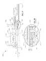
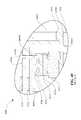
- FIG. 1Ais a schematic diagram of a ball planetary continuously variable transmission (CVT) and certain relevant coordinate systems.
- CVTcontinuously variable transmission
- FIG. 1Bis a diagram of certain relative-coordinate systems related to a coordinate system shown in FIG. 1A .
- FIG. 1Cis a schematic diagram of certain kinematic relationships between certain contacting components of the CVT of FIG. 1A .
- FIG. 1Dis a representative chart of traction coefficient versus relative velocity for a typical traction fluid and rolling contact between CVT traction components.
- FIG. 1Eis a free body diagram of a traction planet of the CVT of FIG. 1A .
- FIG. 1Fis a schematic diagram of a traction planet of the CVT of FIG. 1A showing a skew angle.
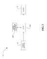
- FIG. 2is a block diagram of an embodiment of a drive apparatus configured to use certain inventive embodiments of CVTs and skew control systems and methods therefor disclosed here.
- FIG. 3is a perspective view of certain components of a CVT configured to employ a skew angle adjustment to cause a tilt in the axis of rotation of traction planets.
- FIG. 4is a block diagram of an embodiment of a skew control system that can be used in, for example, the drive apparatus of FIG. 2 .
- FIG. 5Ais a schematic diagram of another embodiment of a skew control system that can be used with, for example, the drive apparatus of FIG. 2 .
- FIG. 5Bis a schematic diagram of yet another embodiment of a skew control system that can be used with, for example, the drive apparatus of FIG. 2 .
- FIG. 5Cis a schematic diagram of one more embodiment of a skew control system that can be used with, for example, the drive apparatus of FIG. 2 .
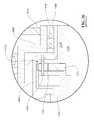
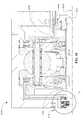
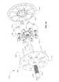
- FIG. 6is a cross-sectional view of a CVT configured to employ a skew angle adjustment to facilitate an adjustment in the speed ratio of the CVT.
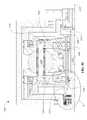
- FIG. 7is a partially sectioned and exploded, perspective view of certain components of the CVT of FIG. 6 .
- the CVTis shown in two pages; wherein a plane perpendicular to the main axis of the CVT and passing through the center of the traction planet divides the CVT in two sections.
- FIG. 8is a partially sectioned and exploded, perspective view of certain components of the CVT of FIG. 6 .
- FIG. 8is the second section, of the CVT illustrated, that compliments the section shown in FIG. 7 .
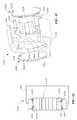
- FIG. 9is a perspective view of a planet-leg assembly that can be used with the CVT of FIG. 6 .
- FIG. 10is a cross-sectional view of the planet-leg assembly of FIG. 9 .
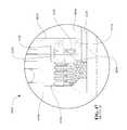
- FIG. 11is a Detail A view of the CVT of FIG. 6 .
- FIG. 12is a Detail B view of the CVT of FIG. 6 .
- FIG. 13is a perspective view of a main axle that can be used with the CVT of FIG. 6 .
- FIG. 14is a cross-sectional view of the main axle of FIG. 13 .
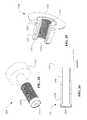
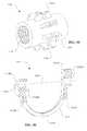
- FIG. 15is a perspective view of a feedback cam that can be used with the CVT of FIG. 6 .
- FIG. 16is a cross-sectional view of the feedback cam of FIG. 15 .
- FIG. 17is perspective view of a skew cam that can be used with the CVT of FIG. 6 .
- FIG. 18is a cross-sectional view of the skew cam of FIG. 17 .
- FIG. 19is a perspective view of a carrier plate that can be used with the CVT of FIG. 6 .
- FIG. 20is a cross-sectional view of the carrier plate of FIG. 19 .
- FIG. 21is a partially sectioned, perspective view of a shift cam that can be used with the CVT of FIG. 6 .
- FIG. 22is a perspective view of a leg assembly that can be used with certain embodiments of a CVT that uses skew control.
- FIG. 23is a cross-sectional view of certain components of the leg of FIG. 22 .
- FIG. 24is a cross-sectional view of another embodiment of a CVT configured to use adjustment of a skew angle to cause adjustment of an angle of rotation of the traction planets of the CVT.
- FIG. 25is a partially sectioned and exploded view of certain components of the CVT of FIG. 24 .
- FIG. 26is a Detail C view of the CVT of FIG. 24 .
- FIG. 27is a perspective view of a main axle that can be used with the CVT of FIG. 24 .
- FIG. 28is a perspective view of a feedback cam that can be used with the CVT of FIG. 24 .
- FIG. 29is a cross-sectional view of the feedback cam of FIG. 28 .
- FIG. 30is a cross-sectional view of a yet another embodiment of a CVT configured to use adjustment of a skew angle to cause an adjustment of the speed ratio.
- FIG. 31is partially sectioned and exploded view of certain components of the CVT of FIG. 30 .
- FIG. 32is a Detail D view of the CVT of FIG. 30 .
- FIG. 33is a perspective view of a feedback cam that can be used with the CVT of FIG. 30 .
- FIG. 34is a cross-sectional view of the feedback cam of FIG. 33 .
- FIG. 35is a partially sectioned, perspective view of a shift cam that can be used with the CVT of FIG. 30 .
- FIG. 36is a cross-sectional view of certain components of an embodiment of a CVT having a skew-based control system and a neutralizer assembly.
- FIG. 37is a cross-sectional view of certain components of another embodiment of a CVT having a skew-based control system and a neutralizer assembly.
- FIG. 38is a Detail E view of the CVT of FIG. 37 .
- FIG. 39is a cross-sectional view of certain components of yet another embodiment of a CVT having a skew-based control system and a neutralizer assembly.
- FIG. 40is a Detail F view of the CVT of FIG. 39 .
- FIG. 41is a cross-section view of one more embodiment of a CVT having a skew-based control system and a neutralizer assembly.
- FIG. 42is a partially cross-sectioned, exploded view of a control reference assembly that can be used with the CVT of FIG. 41 .
- FIG. 43is a cross-sectional view of the control reference assembly of FIG. 42 .
- FIG. 44is a plan view of a control reference nut that can be used with the control reference assembly of FIG. 43 .
- FIG. 45is a cross-sectioned perspective view of an intermediate reaction member that can be used with the control reference assembly of FIG. 43 .
- FIG. 46is a partially cross-sectioned perspective view of the control reference nut of FIG. 44 .
- FIG. 47is a Detail G view of the CVT of FIG. 41 .
- FIG. 48is a cross-sectional view of another embodiment of a CVT having a skew-based control system.
- FIG. 49is a Detail H view of the CVT of FIG. 48 .
- FIG. 50is a partially cross-sectioned exploded view of certain components of the CVT of FIG. 48 .
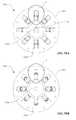
- FIG. 51Ais a plan view of certain components of an embodiment of a CVT having an inventive skew-based control system.
- FIG. 51Bis another plan view of the CVT of FIG. 51A .
- FIG. 52is a cross-sectional view of the CVT of FIG. 51A .
- FIG. 53Ais a Detail I view of the CVT of FIG. 51A .
- FIG. 53Bis a Detail J view of the CVT of FIG. 51A .
- FIG. 54is an exploded perspective view of the CVT of FIG. 51A .
- FIG. 55is a perspective view of a sleeve that cam be used with the CVT of FIG. 51A .
- FIG. 56is a partially cross-sectioned, perspective view of a planet support trunnion that can be used with the CVT of FIG. 51A .
- FIG. 57is a plan view of a torque governor having certain inventive features.
- FIG. 58is a cross-sectional view of the torque governor of FIG. 57 .
- the terms “operationally connected,” “operationally coupled”, “operationally linked”, “operably connected”, “operably coupled”, “operably linked,” and like termsrefer to a relationship (mechanical, linkage, coupling, etc.) between elements whereby operation of one element results in a corresponding, following, or simultaneous operation or actuation of a second element. It is noted that in using said terms to describe inventive embodiments, specific structures or mechanisms that link or couple the elements are typically described. However, unless otherwise specifically stated, when one of said terms is used, the term indicates that the actual linkage or coupling may take a variety of forms, which in certain instances will be readily apparent to a person of ordinary skill in the relevant technology.
- radialis used here to indicate a direction or position that is perpendicular relative to a longitudinal axis of a transmission or variator.
- axialrefers to a direction or position along an axis that is parallel to a main or longitudinal axis of a transmission or variator.
- Traction drivesusually involve the transfer of power between two elements by shear forces in a thin fluid layer trapped between the elements.
- the fluids used in these applicationsusually exhibit traction coefficients greater than conventional mineral oils.
- the traction coefficient ( ⁇ )represents the maximum available traction forces which would be available at the interfaces of the contacting components and is a measure of the maximum available drive torque.
- friction drivesgenerally relate to transferring power between two elements by frictional forces between the elements.
- the CVTs described heremay operate in both tractive and frictional applications.
- the CVTcan operate at times as a friction drive and at other times as a traction drive, depending on the torque and speed conditions present during operation.
- Embodiments of the invention disclosed hereare related to the control of a variator and/or a CVT using generally spherical planets each having a tiltable axis of rotation that can be adjusted to achieve a desired ratio of input speed to output speed during operation.
- adjustment of said axis of rotationinvolves angular misalignment of the planet axis in one plane in order to achieve an angular adjustment of the planet axis in a second plane, thereby adjusting the speed ratio of the variator.
- the angular misalignment in the first planeis referred to here as “skew” or “skew angle”.
- a control systemcoordinates the use of a skew angle to generate forces between certain contacting components in the variator that will tilt the planet axis of rotation.
- the tilting of the planet axis of rotationadjusts the speed ratio of the variator.
- a coordinate systemis established with respect to the traction planet, followed by a discussion of certain kinematic relationships between contacting components that generate forces which tend to cause the planet axis to tilt in the presence of a skew angle.
- Embodiments of skew control systems for attaining a desired speed ratio of a variatorwill be discussed.
- An embodiment of a CVT 100includes generally spherical traction planets 108 in contact with a traction sun 110 .
- the traction planets 108are also in contact with a first traction ring 102 and a second traction ring 104 at, respectively, a first angular position 112 and a second angular position 114 .
- a global coordinate system 150(that is, x g , y g , z g ) and a planet-centered coordinate system 160 (that is, x, y, z) are defined in FIG. 1A .
- the global coordinate system 150is generally oriented with respect to a longitudinal axis or main drive axis 152 of the CVT 100 , for example with the z g -axis coinciding with the main drive axis 152 about which the traction planets 108 are arranged.
- the planet-centered coordinate system 160has its origin at the geometric center of the traction planet 108 with the y-axis generally bisecting the angle formed between the traction rings 102 , 104 and the z-axis generally parallel to the main drive axis 152 .
- Each of the traction planets 108has an axis of rotation, that is, a planet axis 106 , which can be configured to tilt in the y-z plane to thereby form a tilt angle 118 (sometimes referred to here as ⁇ ).
- the tilt angle 118determines the kinematic speed ratio between the traction rings 102 , 104 .
- Each of the planets 108has a rotational velocity about the planet axis 106 and is shown in FIG.
- the planet axis 106corresponds to a planet axle, which is operationally coupled to a carrier or a cage (not shown) that can be stationary, while in other embodiments the planet axle is coupled to a carrier (not shown) that is rotatable about main drive axis 152 .
- the x-axisis directed into the plane of the page and the z-axis is generally parallel to the main drive axis 152 , consequently the tilt angle 118 is generally coplanar with the main drive axis 152 .
- a tilt angle 118can be derived by rotating the coordinate system 160 with the planet axis 106 in the y-z plane about the x-axis to achieve a first relative coordinate system 170 (x′, y′, z′).
- the planet axis 106coincides with the z′-axis.
- a skew angle 120(sometimes referred to here as ç) can be obtained in a x′-z′ plane, which is defined in a second relative coordinate system 180 (x′′, y′′, z′′).
- the skew angle 120can be considered, approximately, the projection in the x-z plane of the angular alignment of the planet axis 106 . More specifically, however, the skew angle 120 is the angular position of the planet axis 106 in the x′-z′ plane as defined by the relative coordinate systems 170 and 180 .
- the skew angle 120is generally not coplanar with the main drive axis 152 .
- the tilt angle 118can be adjusted directly to adjust the speed ratio. In one embodiment of the CVT 100 , the tilt angle 118 is controlled, at least in part, through an adjustment of the skew angle 120 .
- skew conditionrefers to an arrangement of the planet axis 106 relative to the main drive axis 152 such that a non-zero skew angle 120 exists.
- inducement of a skew conditionimplies an inducement of the planet axis 106 to align at a non-zero skew angle 120 .
- certain spin-induced forcesalso act on the traction plane 108 .
- FIG. 1Cto reflect a view of the x′′-z′′ plane as seen from a reference above the CVT 100 , or View A in FIG. 1A . Since the contact areas 1, 2, 3 are not coplanar, contact-centered coordinate systems are used in FIG. 1C so that the contact areas 1, 2, 3 can be illustrated with the x′′-z′′ plane. Subscripts 1, 2, and 3 are used to denote the specific contact area for contact-centered coordinate systems.
- the z 1,2,3 -axisare directed at the center of the traction planet 108 .
- the surface velocity of the first traction ring 102is denoted in the negative x 1 direction by a vector V r1 and the surface velocity of the planet 108 is represented by a vector V p1 ; the angle formed between the vectors V r1 and V p1 is the skew angle 120 .
- the resulting relative surface velocity between the traction ring 102 and the traction planet 108is represented by a vector V r1/p .
- the surface velocity of the traction sun 110is represented by a vector V sv and the surface velocity of the traction planet 108 is represented by a vector V ps ; the angle formed between V sv and V ps is the skew angle 120 .
- the relative surface velocity between the traction planet 108 and the traction sun 110is represented by a vector V sv/p .
- the surface velocity of the traction planet 108 at the contact area 2is shown as a vector V p2 and the surface velocity of the second traction ring 104 is represented by a vector V r2 ; the angle formed between V p2 and V r2 is the skew angle 120 ; the relative surface velocity between the traction planet 108 and the second traction ring 104 is the resultant vector V r2/p .
- FIG. 1Dshows a generalized, representative traction curve that can be applied at each of contact areas 1, 2, 3.
- the graphillustrates the relationship between the traction coefficient ⁇ and the relative velocity between contacting components.
- the traction coefficient ⁇is indicative of the capacity of the fluid to transmit a force.
- the relative velocitysuch as V r1/p , can be a function of the skew angle 120 .
- the traction coefficient ⁇is the vector sum of the traction coefficient in the x-direction ⁇ x and the traction coefficient in the y-direction ⁇ y at a contact area 1, 2, or 3.
- the traction coefficient ⁇is a function of the traction fluid properties, the normal force at the contact area, and the velocity of the traction fluid in the contact area, among other things.
- the traction coefficient ⁇increases with increasing relative velocities of components, until the traction coefficient ⁇ reaches a maximum capacity after which the traction coefficient ⁇ decays. Consequently, in the presence of a skew angle 120 (that is, under a skew condition), forces are generated at the contact areas 1, 2, 3 around the traction planet 108 due to the kinematic conditions. Referring to FIGS. 1C and 1E , V r1/p generates a force F s1 parallel to the V r1/p .
- Increasing the skew angle 120increases the V r1/p and, thereby, increases the force F s1 according to the general relationship shown in FIG. 1D .
- the V sv/pgenerates a force F ss
- the V r2/pgenerates a force F s2 .
- the forces F s1 , F ss , and F s2combine to create a net moment about the traction roller 108 in the y-z plane.
- the traction coefficient ⁇is a function of relative velocity between contacting components
- the traction coefficients ⁇ y1 , ⁇ y2 , and ⁇ ysare consequently a function of the skew angle 120 as related by the kinematic relationship.
- a momentis the acceleration of inertia; hence, in the embodiment illustrated here, the moment will generate a tilt angle acceleration ⁇ ′′. Therefore, the rate of change of the tilt angle ⁇ ′ is a function of the skew angle 120 .
- spin-induced forcescan be generated at the contacting areas.
- the spin-induced forcestend to resist the skew-induced forces.
- the spin-induced forces and the skew-induced forcescan be reacted axially through the traction sun 110 , and are sometimes referred to here as axial forces or side forces.
- Embodiments of the CVT 100can be configured such that the planet axis 106 tilts when the skew-induced forces are larger than the spin-induced forces.
- the skew-induced forces and the spin-induced forcescan balance each other, resulting in the CVT operating under a skew condition.
- auxiliary side force reaction acting on the traction sun 110that is, in some embodiments of the CVT, the axial position of the traction sun 110 is constrained axially by a mechanism other than the skew-induced forces.
- a traction planet 108is illustrated having a tilt angle 118 equal to zero, which results in the planet axis 106 being generally coplanar to the main drive axis 152 of the CVT 100 and the rotational velocity 122 of the traction planet 108 is coaxial with the z-axis.
- a skew angle 120can be formed in the x-z plane to generate forces for motivating a change in the tilt angle 118 .
- the traction planet 108would have a rotational velocity 122 about an axis z′′, and the tilt angle 118 would be formed in the y-z′ plane.
- FIG. 2shows a drive 25 that includes a CVT 300 operationally coupled between a prime mover 50 and a load 75 .
- the drive 25can also include a skew-based control system 200 .
- the prime mover 50delivers power to the CVT 300
- the CVT 300delivers power to a load 75 .
- the prime mover 50can be one or more of various power generating devices
- the load 75can be one or more of various driven devices or components. Examples of the prime mover 50 include, but are not limited to, human power, engines, motors and the like.
- the skew control system 200can coordinate the operation of the CVT 300 as well as the prime mover 50 , or can coordinate the operation of the CVT 300 and the load 75 , or can coordinate the operation of all elements in the drive apparatus 25 .
- the skew control system 200can be configured to use an adjustment of a skew angle 120 to control the operating condition of the CVT 300 , and consequently, coordinate the control of the drive 25 .
- a skew lever 302can be operationally connected to carrier plate 304 in such a manner that a rotation of the skew lever 302 causes a rotation of the carrier plate 304 with respect to a main axle 312 .
- a second carrier plate 306is rigidly coupled to the main axle 312 .
- a traction planet assembly 311 and a traction sun assembly 310are arranged to operate between the two carrier plates 304 and 306 .
- One end of the planet axis 106is operably coupled to the carrier plate 304 , and the other end of planet axle 106 is operably coupled to the carrier plate 306 .
- the planet-centered coordinate system 160is shown in the planet assembly 308 in FIG. 3 for reference.
- An angular rotation of the skew lever 302causes a rotation of the carrier plate 304 to a carrier plate angle 324 (sometimes referred to as carrier plate angle 13 . Since the planet axis 106 is constrained by the carrier plates 304 and 306 , the planet axis 106 will adjust to a position that is no longer coplanar with the axis of the main axle 312 ; resulting in the inducement of a skew condition.
- a linear relation between an axial translation of the traction sun 310 and the tilt angle 118can be expressed as follows.
- RSFdescribes the transverse creep rate between the traction planet 308 and the traction sun 310 .
- “creep”is the discrete local motion of a body relative to another and is exemplified by the relative velocities of rolling contact components as previously discussed.
- the skew-based control system 205can include a skew dynamics module 202 , which can be defined by a transfer function, for example.
- the skew dynamics module 202abides by the kinematic relationships described previously between a skew angle 120 and the generation of forces that tend to motivate an adjustment in the tilt angle 118 .
- the operating condition of the CVT 300can be used as input for the skew dynamics module 202 and can be generally represented by the normal force (that is, F N ) at the contact areas and the rotational velocity ⁇ of the traction planet 308 .
- a control reference 208can be a desired skew angle 120 , for example.
- the control reference 208is compared to a feedback value 201 at the summing junction 210 .
- the feedback value 201is indicative of an actual skew angle under the current operating conditions.
- the resulting skew angle ⁇is provided to the skew dynamics module 202 , which returns a rate of change in the tilt angle ⁇ ′; integration of ⁇ ′ with integrator 204 returns a tilt angle ⁇ .
- the tilt angle ⁇is further processed by a gain (K) 2050 to provide feedback to the summing junction 210 .
- the control reference 208can be a position reference of the traction sun 110 , a desired tilt angle ⁇ , or any other parameter relevant to the operation of the CVT 300 , such as a speed ratio or a torque ratio.
- the control reference 208can be converted where appropriate to provide a reference skew angle ⁇ R .
- the control reference 208can be an angular position reference such as a rotation of a shift nut or a reference dial, which is coupled to a planetary gear set having a ratio (K 1 ) 500 .
- An angular position of a planetary gear setcan be transformed into an axial translation of a reference element by using, for example, a screw lead (K 2 ) 502 , and can be compared to an axial position of a traction sun 110 (again, for example) to derive a control error 408 .
- an axial positionsuch as the axial position of a shift rod (not shown), can be used as the control reference 208 .
- the control reference 208is compared to a feedback 404 , which in this case is the axial position of the traction sun 110 , at the summing junction 412 to derive the control error 408 . It is preferable to convert the physical units of the control reference 208 and the feedback 404 so that the two parameters have the same units prior to the summing junction 412 for arithmetic consistency.
- a gain (K 3 ) 406can be applied to convert the control error 408 into a carrier plate angle ⁇ , such as the carrier plate angle 324 shown in FIG. 3 , for example.
- the gain 406can be a screw lead.
- the carrier plate angle ⁇can be actuated by a skew lever 302 as shown in FIG. 3 , for example.
- a skew algorithm 400includes a function 203 coupled to the skew dynamics module 202 .
- the function 203is configured to convert the carrier plate angle ⁇ into a skew angle ⁇ .
- the skew algorithm 400receives the carrier plate angle ⁇ as input and returns a rate of change in tilt angle ⁇ ′.
- an integrator 410can be applied to the result of the skew dynamics module 202 to derive a tilt angle ⁇ , which determines a speed ratio of a CVT.
- a speed ratio (SR) 420can be derived from ⁇ by a function 418 having as inputs the normal force F N and the rotational speed of the traction planet 108 .
- the tilt angle ⁇can also be transformed into a feedback 404 by applying a gain (K4) 402 .
- the skew algorithm 400is a transfer function based on the specific operating conditions of a CVT.
- the skew algorithm 400can take the form of a look up table that can be created by empirically determining ⁇ ′ for a given carrier plate angle ⁇ and operating conditions of a CVT.
- testscan be performed on a specific CVT where the input operating condition is held at discrete speeds and loads appropriate for the intended application, while discrete steps in the carrier plate angle ⁇ can be applied to the system so that the speed ratio change of the CVT can be measured and used to calculate the resultant ⁇ ′.
- the resultant datacharacterizes the dynamic response of the system and can be formulated into a look-up table or function used for the skew algorithm 400 .
- the skew control system 207includes the control reference 208 coupled to a planetary gear set having a ratio (K 1 ) 500 .
- the control reference 208can be adjusted by the application of a torque 209 to the shift nut or reference dial.
- the control reference 208 applied with a torque 209can be transformed into an axial translation of a reference element, such as a feedback cam 1066 having a screw lead (K 2 ) 502 .
- the skew control system 207includes two summing junctions 501 and 503 .
- the first summing junction 501produces the control error 408 based on a control reference 208 and two sources of feedback.
- a first feedback sourcecan be the axial position of the traction sun 110
- the other feedback sourcecan be the axial position of the skew cam 1068 (see FIG. 6 ), for example.
- the second summing junction 503sums forces exerted on the skew cam 1068 .
- the result of the summing junction 503is, therefore, a force exerted on the skew cam 1068 that can be used to determine the axial position of the skew cam 1068 .
- the position ⁇ of the skew cam 1068is determined by dividing the resultant force of the summing junction 503 by the mass of the skew cam 1068 , shown as gain 508 , and integrating the resulting skew cam acceleration ⁇ ′′ with integrators 410 , once to determine speed ⁇ ′ of the skew cam 1068 and again to determine the position ⁇ .
- the axial position ⁇is provided as input to the summing junction 501 and combined with the control reference 208 and the axial position of the traction sun to derive a control error 408 .
- a gain (K 3 ) 406can be applied to convert the control error 408 into a carrier plate angle ⁇ .
- the skew algorithm 400receives a carrier plate angle ⁇ as input and returns a rate of change in tilt angle ⁇ ′.
- An integrator 410is applied to ⁇ ′ to provide a tilt angle ⁇ that can be further transformed into an axial position of traction sun by applying a gain (K 4 ) 402 .
- the summing junction 503sums forces exerted on, for example, the skew cam 1068 .
- the forcescan include friction 510 , neutralizing spring force 512 , control reference force 514 , carrier plate force 516 , and axial forces 518 on the traction sun 110 , 1026 , which is typically produced at the contact area 3 between the traction sun 110 , 1026 and the traction planet 108 , 1022 , for example.
- friction exerted on the skew cam 1068can be determined from the velocity of the skew cam 1068 and the screw lead of the skew cam 1068 with a function 511 .
- Neutralizing spring force 512can be determined by applying a gain (K 5 ) 513 to the control error 408 formed at the summing junction 501 .
- the gain (K 5 ) 513can represent a mechanical system that tends to bias a skew cam 1068 , for example, to a neutral location through linear, non-linear, or discontinuous functions, such as the neutralizer assembly 1092 shown in FIG. 6 .
- a forcecan be generated by the reference torque 209 exerted while adjusting the control reference 208 .
- the control reference force 514is determined by applying a gain (K 6 ) 515 proportional to the effective lever arm of the torque 209 applied to the skew cam 1068 .
- the drive torque ( ⁇ ) 521is reacted by the carrier plates 304 and 306 .
- the carrier plate 304can be configured to react the drive torque ( ⁇ ) 521 and to actuate the skew angle ⁇ , for instance, by a skew lever 302 or a skew cam 1068 .
- the carrier plate torque function 520provides a carrier plate torque 522 based on the drive torque ( ⁇ ) 521 and the tilt angle ⁇ .
- the resulting carrier plate force 516 acting on the skew cam 1068is determined by applying to the carrier plate torque 522 a gain (K 7 ) 517 , which is proportional to the distance from the skew cam 1068 that the carrier plate torque is acting on the skew cam 1068 .
- the axial force 518 on the traction sunis reacted on the skew cam 1068 in some embodiments.
- the axial force 518is generated by spin-induced and skew-induced side forces at the contact area 3.
- the force 518can be determined by the traction sun force algorithm 519 that is a function of, among other things, the normal force at contact 3 and the rotational speed ⁇ of the traction planet 108 , 308 , or 1022 .
- the forces just describedare combined at the summing junction 503 and are used in the skew control system 207 for feedback to account for the steady state operating error that can exist in the skew angle ç.
- a steady state error in the skew angle çcan arise when operating the CVT 300 due to reacting the spin-induced side forces on the traction sun.
- the embodiment of a skew control system shown in FIG. 6incorporates a side force neutralizer assembly 1092 that effectively reacts the side forces on the traction sun 1026 so that the skew angle ç is at an optimal operating skew condition ç opt , which in some cases means a substantially zero skew angle ç during steady state operation.
- a traction sun position locker 530can be coupled to a traction sun and integrated with the skew control system 2000 .
- the traction sun position locker 530can be, for example, a mechanism that locks and holds the traction sun at an axial position until the lock is released.
- the mechanismcan be a mechanical locking pawl, or an electro-mechanically actuated device, or an electro-hydraulically actuated device.
- the state of the traction sun position lockeris based on a result from a decision process 532 that compares the control error 408 with an upper and lower limit for the error. If the control error 408 is within the limits set in the decision process 532 , the positive or true result from the process 532 is sent to the traction sun position locker 530 , which returns a command 531 to lock the traction sun at its current position. A positive or true result from the decision process 532 is also sent to a skew angle ç coordinator 534 that returns a command 536 to set the skew angle ç to an optimal skew angle ç opt , which is some embodiments it means that the skew angle ç is zero.
- control error 408can be determined by comparing a control reference 208 to a feedback 404 .
- a control reference 408can be a position, either angular or axial, a desired speed ratio, or any other relevant reference for operating a CVT 300 .
- a mechanical, electrical, or hydraulic speed governorcan be coupled to the shift nut or control reference in order to adjust the operating condition of the drive.
- a skew control systemsuch control system 200 described here, can be coupled to a mechanism for controlling input torque in the presence of a varying output torque.
- the CVT 1000includes a housing formed generally by a shell 1010 and a cap 1012 ; the shell 1010 and the cap 1012 can be rigidly coupled with, for example, bolts, screws, or a threaded joint.
- a power input member 1014such as a sprocket for example, couples to an input driver 1018 , which is positioned coaxially with a longitudinal axis LA 1 of the CVT 1000 .
- a first axial force generator 1016is placed between the input driver 1018 and a first traction ring 1020 .
- An array of traction planets 1022is positioned on a plane perpendicular to the longitudinal axis LA 1 .
- the traction planets 1022are arranged angularly about the longitudinal axis LA 1 , and are placed in frictional or tractive contact with the first traction ring 1020 , a second traction ring 1024 , and a traction sun 1026 .
- the shell 1010is adapted to receive torque from, or transmit torque to, the second traction ring 1024 .
- a shell torque member 1028couples to the second traction ring 1024 via a second axial force generator 1030 .
- the traction ring 1024 , traction sun 1026 , and the axial force generators 1016 , 1030are mounted coaxially with the longitudinal axis LA 1 .
- the shell 1010 and the cap 1012are supported radially by bearings 1032 , 1034 , respectively.
- the bearing 1032provides a rolling interface between the shell 1010 and an axial retainer plate 1084 .
- the bearing 1034provides a rolling interface between the cap 1012 and the input driver 1018 .
- a thrust bearing 1036can be positioned between the input driver 1018 and the cap 1012 to provide an axial rolling interface between the input driver 1018 and the cap 1012 , which cap 1012 reacts axial forces generated during operation of the CVT 1000 .
- a main axle 1038can be provided to, in part, support various component of the CVT 1000 and to, in some embodiments, provide for attachment of the CVT 1000 to a frame of a vehicle, a support bracket, a fixed member of a machine, or the like.
- the CVT 1000includes carrier plates 1040 , 1042 adapted to, among other things, support radially and axially an array of planet-leg assemblies 1044 , which will be described further with reference to FIGS. 9 and 10 .
- stator spacers(not shown) can be provided to attach the carrier plates 1040 , 1042 together.
- the carrier plates 1040 , 1042are coupled only semi-rigidly (rather than rigidly) to allow some relative rotation between the carrier plate 1040 and the carrier plate 1042 .
- at least one of the carrier plates 1040 , 1042can be adapted to facilitate adjustment of the speed ratio of the CVT 1000 .
- a planet-leg assembly 1044generally includes, among other things, a traction planet 1022 mounted about a planet axle 1046 .
- one or more bearings 1048can be provided between the planet axle 1046 and a bore of the traction planet 1022 .
- the planet axle 1046is configured to extend beyond the circumference of the traction planet 1022 .
- a leg 1050couples to the planet axle 1046 .
- the leg 1050is sometimes characterized as a shift lever because the leg 1050 acts as a lever to facilitate a tilt of the planet axle 1046 , which results in an adjustment (or shift) of the speed ratio between the traction rings 1020 , 1024 .
- the leg 1050is adapted to receive and support a shift cam roller 1052 and a shift guide roller 1054 .
- the shift cam rollers 1052are adapted to transmit force from shift cams 1056 , 1058 (see FIG. 6 ) to the legs 1050 for, among other things, facilitating a speed ratio adjustment.
- the shift guide rollers 1054are generally adapted to cooperate with the carrier plates 1040 , 1042 to react forces that arise during a speed ratio adjustment.
- each of the planet axles 1046is provided with a skew roller 1060 to, in part, react forces that tend to misalign (that is, remove the coplanarity between) a longitudinal axis of the planet axle 1046 and the longitudinal axis LA 1 .
- planet-leg assembly 1044 described hereis merely one example of a variety of planet-leg assemblies that can be used with the CVT 1000 .
- Other suitable planet-leg assemblies and/or legs,are described in U.S. Patent Application 60/943,273, filed on Jun. 11, 2007, and which is hereby incorporated by reference herein in its entirety.
- the flow of power through the CVT 1000proceeds generally as follows. Power is input to the power input member 1014 .
- the input driver 1018receives the power from the input member 1014 and drives the axial force generator 1016 .
- Powerflows from the axial force generator 1016 into the first traction ring 1020 , which through friction or traction drives the traction planets 1022 .
- the second traction ring 1024receives power from the traction planets 1022 and transfers power to the second axial force generator 1030 .
- Powerflows from the second axial force generator 1030 to the shell 1010 via the shell torque member 1028 . Power can then be delivered from the shell 1010 to a load, final drive, machine, gearbox, planetary gearset, etc.
- the power flow just describedcan be reversed such that power is input via the shell 1010 and transmitted from the second axial force generator 1030 , to the second traction ring 1024 , and so on, and delivered to the power input member 1014 (in which case, the power input member 1014 is more precisely characterized as a power output member). It should be additionally noticed that in some applications it might be preferable to provide a power output shaft (not shown) that can be coupled to the second axial force generator 1030 , which allows the shell 1010 to be removed from the power flow and to be held stationary relative to the power flow components.
- Adjustment in the speed ratio between the traction rings 1020 , 1024can be accomplished by tilting the axis of the planet axles 1046 relative to the longitudinal axis LA 1 .
- mechanisms and methods for actuating and controlling a tilting of the planet axles 1046will be described.
- a reference input nut 1062is mounted coaxially with the longitudinal axis LA 1 and coupled via a sliding spline interface 1064 to a feedback cam 1066 .
- the sliding spline interface 1064is configured to allow the reference input nut 1062 to rotate the feedback cam 1066 , and to allow the feedback cam 1066 to translate axially relative to the reference input nut 1062 .
- a skew cam 1068includes a first threaded portion 1070 adapted to couple to a mating threaded portion 1122 of the feedback cam 1066 (see FIGS. 15-18 ).
- the skew cam 1068additionally includes a second threaded portion 1072 configured to mate with a corresponding threaded portion 1074 of the carrier plate 1042 .
- the main axle 1038is provided with a splined portion 1076 that mates to a splined portion 1082 of the skew cam 1068 .
- the splined interface between the main axle 1038 and the skew cam 1068facilitates anti-rotation, but allows relative axial translation, of the skew cam 1068 relative to the main axle 1038 .
- the reference input nut 1062 , feedback cam 1066 , and skew cam 1068are mounted concentrically with the main axle 1038 .
- the reference input nut 1062is turned to a selected position indicative of a desired speed ratio. If the axial forces (or, in other words, the clamping load provided by the axial force generators that yield a normal force at the contact) on the traction planets 1022 is relatively low or substantially zero, through the splined interface 1064 the reference input nut 1062 causes the feedback cam 1066 to rotate about the longitudinal axis LA 1 . Hence, when the clamp loads on the traction planets 1022 are relatively low, the skew cam 1068 tends not to translate. Consequently, the feedback cam 1066 is forced to translate axially as the feedback cam 1066 rotates about the axis LA 1 .
- the axial translation of the feedback cam 1066causes an axial translation of the traction sun 1026 via thrust bearings 1078 , 1080 .
- Axial translation of the traction sun 1026results in a tilting of the planet axles 1046 through the operational coupling between the traction sun 1026 and the planet axles 1046 via the shift cams 1056 , 1058 , shift cam rollers 1052 , and legs 1050 .
- the carrier plate 1042Since the carrier plate 1042 is constrained axially but can have at least some angular rotation, the carrier plate 1042 is urged into angular rotation about the longitudinal axis LA 1 through the sliding spline interface 1072 , 1074 between the skew cam 1068 and the carrier plate 1042 , resulting in the carrier plate 1042 inducing the planet axles 1046 into a skew condition.
- the carrier plate 1042rotates angularly until a maximum skew angle is achieved.
- the skew conditioncauses a tilting of the planet axles 1046 .
- the tilting of the planet axles 1046results in an adjustment of the speed ratio of the CVT 1000 .
- the tilting of the planet axles 1046additionally acts to translate axially the shift cams 1056 , 1058 via the operational coupling between the planet axles 1046 and the shift cams 1056 , 1058 .
- the axial translation of the shift cams 1056 , 1058consequently results in an axial translation of the feedback cam 1066 via the thrust bearings 1078 , 1080 . Since the reference input nut 1062 prevents rotation of the feedback cam 1066 , the skew cam 1068 and the feedback cam 1066 translate axially together.
- the axial translation of the skew cam 1068causes a restoring angular rotation upon the carrier plate 1042 , which consequently returns to a skew angle that generates sufficient skew forces to maintain the skew cam 1068 at an equilibrium axial position.
- the CVT 1000When the CVT 1000 is under an operation condition that is between a no load condition and a loaded condition, there can exist a cross over condition under which inducement of a skew condition of the planet axles 1046 (as well as the restoring action to zero skew condition) involves a translation and a rotation of the feedback cam 1066 with a simultaneous translation of the skew cam 1068 .
- the feedback cam 1066 and the skew cam 1068are configured to cooperate to induce a skew condition of the planet axles 1046 via an angular rotation of the carrier plate 1042 .
- the skew conditioncauses a tilting of the planet axles 1046 to set the CVT 1000 at a desired speed ratio.
- the feedback cam 1066under action from the planet-leg assemblies 1044 , cooperates with skew cam 1068 to restore the carrier plate 1042 to a position that induces a nominal zero skew.
- the carrier plate 1042is constrained axially by the axial retainer plate 1084 and an axial retainer cap 1086 , which cooperate with thrust bearings 1088 , 1090 , as shown in Detail View B of FIGS. 6 and 12 .
- the axial retainer plate 1084 , axial retainer cap 1086 , and the thrust bearings 1088 , 1090are mounted coaxially about the longitudinal axis LA 1 , and are configured to facilitate an axial constraint of the carrier plate 1042 while allowing an angular rotation of the carrier plate 1042 about the longitudinal axis LA 1 .
- the axial retainer plate 1084is preferably coupled rigidly to the main axle 1038 ; that is, the retainer plate 1084 is configured in some embodiments to be constrained axially, radially, and rotationally relative to the longitudinal axis LA 1 .
- the carrier plate 1040is constrained axially, radially, and rotationally relative to the longitudinal axis LA 1 , which constrains can be achieved by, for example, coupling rigidly the carrier plate 1040 to the main axle 1038 .
- the interface between the carrier plate 1040 and the input driver 1018is provided with a rolling bearing surface, or bearings, to allow relative rotation between the carrier plate and the input driver 1018 with minimal friction.
- the traction sun 1026tends to be subjected to an axial force (also, referred to as a “spin-induced side force”) through the contact between the traction planets 1022 and the traction sun 1026 during operation of the CVT 1000 .
- an axial forcealso, referred to as a “spin-induced side force”
- spin-induced side forcealso, referred to as a “spin-induced side force”
- the traction sun 1026will tend to induce an axial translation of the skew cam 1068 , resulting in operation at a non-zero skew angle.
- the spin-induced side force on the traction sun 1026is balanced, at least in part, by a skew-induced side force; hence, the skew cam 1068 is held in equilibrium.
- a skew-induced side forcehence, the skew cam 1068 is held in equilibrium.
- the spin-induced side forcesare preferably balanced by a force other than a skew-induced side force.
- the CVT 1000can be provided with a side force neutralizer assembly 1092 , which is generally shown in Detail A view of FIGS. 6 and 11 .
- the neutralizer 1092includes a first resistance member 1094 (such as one or more coil springs, wave springs, belleville springs, etc.) positioned between the axial retainer plate 1084 and a translating resistance cup 1096 .
- the first resistance member 1094 and the translating resistance cup 1096are mounted adjacent to one another and coaxially about the longitudinal axis LA 1 .
- a neutralizer reaction flange 1098can be coupled to the skew cam 1068 .
- the neutralizer reaction flange 1098is positioned adjacent to the translating resistance cup 1096 .
- a second resistance member 1100is positioned between the neutralizer reaction flange 1098 and a neutralizer stop cap 1102 that can be rigidly mounted to the resistance cup 1096 , all of which are mounted coaxially about the longitudinal axis LA 1 .
- the neutralizer stop cap 1102is axially constrained by, for example, the carrier plate 1042 .
- the tendency of the feedback cam 1066 and the skew cam 1068 to translate axiallyis resisted by either one of the resistance members 1094 , 1100 . If axial translation of the skew cam 1068 is to the left (based on the orientation of the CVT 1000 in FIG. 6 ), the neutralizer reaction flange 1098 coupled to the skew cam 1068 pushes on the translating resistance cup 1096 .
- the first resistance member 1094supported axially by the axial retainer plate 1084 , provides a countering force on the neutralizer reaction flange 1098 through the translating resistance cup 1096 .
- the first resistance member 1094is configured to counteract translation of the skew cam 1068 in a first direction towards the carrier plate 1042 .
- the second resistance member 1100is supported axially by the neutralizer stop cap 1102 and provides a counteracting force that tends to resist the axial translation of the skew cam 1068 in the second direction.
- the translating resistance cup 1096is configured to facilitate a decoupling of the action of the resistance members 1094 , 1100 .
- the resistance of the resistance members 1094 , 1100is appropriately selected to allow a translation of the skew cam 1068 at a desired operation condition of the CVT 1000 when a speed ratio adjustment is desired.
- the resistance of the resistance members 1094 , 1100is suitably selected to provide generally only the minimum sufficient resistance needed to counteract the side force on the traction sun 1026 .
- the resistance members 1094 , 1100can have variable resistance and vary with the operating condition of CVT 1000 , so that the optimal resistance is provided to the skew cam 1068 to neutralize the forces induced on the skew cam 1068 .
- the main axle 1038includes a generally elongated, cylindrical body 1104 .
- the main axle body 1104can be provided with a sliding spline portion 1076 , which is preferably configured to mate to a corresponding sliding spline portion 1082 of the skew cam 1068 .
- the main axle body 1104can exhibit a bearing seat 1106 for receiving and supporting one or more main axle radial bearings 1108 that provide coaxial support between the main axle 1038 and the skew cam 1068 with minimal sliding friction.
- the main axle 1038is configured with a bearing seat 1110 for receiving and supporting one or more feedback cam bearings 1112 that provide coaxial support between the main axle 1038 and the feedback cam 1066 with minimal sliding friction.
- the bearings 1108 , 1112are axial roller bearings, or can be replaced by a sliding interface between the main axle 1038 and, respectively, the skew cam 1068 and feedback cam 1066 .
- the main axle 1038can be provided with a main axle flange 1114 that, among other things, provides a piloting surface 1115 for receiving the reference input nut 1062 .
- the main axle flange 1114can have a shoulder 1116 for providing an axial constraint for the reference input nut 1062 .
- the feedback cam 1066includes a generally elongated, cylindrical, hollow body 1118 .
- a bore 1120 of the feedback cam 1066is configured to allow the feedback cam 1066 to be mounted coaxially about the main axle 1038 .
- the bore 1120can exhibit a threaded portion 1122 adapted to engage a corresponding threaded portion 1070 of the skew cam 1068 .
- One portion of the feedback cam 1066is preferably provided with a sliding spline 1124 adapted to mate with a corresponding sliding spline 1064 of the reference input nut 1062 .
- the feedback cam 1066can be provided with one or more bearing races 1126 , 1128 to form part of the thrust bearings 1078 , 1080 (see FIG. 6 ).
- the skew cam 1068includes a generally elongated, hollow, cylindrical body 1130 .
- the skew cam 1068can be provided with a first threaded portion 1070 adapted to engage a mating threaded portion 1122 of the feedback cam 1066 .
- the skew cam 1068can be configured additionally with a second threaded portion 1072 for engaging a mating threaded portion 1074 of the carrier plate 1042 .
- the lead of the first thread portion 1070is relatively smaller than the lead of the second threaded portion 1072 ; for example, the lead of the first threaded portion 1070 can be about 10-30 mm, and the lead of the second threaded portion 1072 can be about 100-300 mm.
- the leads for the first and second threaded portions 1070 , 1072are, respectively, 20 mm and 200 mm (or, in other words, in a ratio of about 1:10).
- a neutralizing reaction flange 1098is formed integral with the skew cam 1068 . However, in other embodiments, the neutralizer reaction flange 1098 can be provided separately and suitably configured to be coupled to the skew cam 1068 .
- a bore 1132 of the skew cam 1068can be adapted to allow the skew cam 1068 to be mounted about the main axle 1038 .
- at least a portion of the bore 1132is provided with a sliding spline 1082 configured to mate with a corresponding sliding spline 1076 of the main axle 1038 .
- the skew cam 1068can be formed with a splined portion 1133 on the outer diameter of the body 1130 , arranged axially for mating with sliding splines 1144 formed on the shift cam 1056 to facilitate anti-rotation of the shift cam 1056 about the longitudinal axis LA 1 .
- a carrier plate 1042can be generally a plate or frame, mounted coaxially with the main axle 1038 , for supporting and guiding the skew rollers 1060 and/or the shift guide rollers 1054 .
- the carrier plate 1042includes a threaded central bore 1074 adapted to engage the threaded portion 1072 of the skew cam 1068 .
- the carrier plate 1042includes surfaces 1134 that are generally concave and are adapted to support the shift guide rollers 1054 as the CVT 1000 is shifted.
- the carrier 1042is provided with reaction surfaces 1136 , angularly arranged about the central bore 1074 , for reacting forces transmitted through the skew rollers 1060 as the CVT 1000 is in operation.
- the carrier plate 1042can be provided with an outer ring 1137 having on one side a face 1138 and on the other side a face 1140 for mating with thrust bearings 1088 and 1090 .
- the carrier plate 1042can also have a reaction face 1142 to facilitate the axial constraint of the neutralizer stop cap 1102 in one direction.
- the shift cam 1056is generally a cylindrical body with a splined inner bore 1144 configured to couple with the sliding spline 1133 of the skew cam 1068 .
- the shift cam 1056is provided with a profiled surface 1146 for guiding the shift cam rollers 1052 .
- Two bearing races 1148 and 1150are formed into the shift cam 1056 for cooperating with, respectively, the bearing balls of the bearing 1080 and the bearing balls supporting the traction sun 1026 .
- the leg assembly 1051can include a leg 1053 having, on one end, a bore 1152 for receiving the planet axle 1046 , and on another end, a slot 1154 to receive the shift cam roller 1052 .
- a bore 1156is formed generally perpendicular to the slot 1154 to retain an axle (not shown) for securing the shift cam roller 1052 .
- a shift guide roller axle 1158can be supported in a bore 1160 while being provided with clearance bores 1162 and 1164 .
- the clearance bores 1162 , 1164facilitate proper coupling between shift guide rollers 1159 and skew reaction rollers 1161 and carrier plates 1040 , 1042 during a shift of the speed ratio induced by a skew condition.
- the bores 1160 , 1162 , and 1164are suitably configured to allow a swiveling or pivoting of the shift guide roller axle 1158 about substantially the center of the shift guide roller axle 1158 .
- the skew reaction rollers 1161 and/or the shift guide rollers 1159are preferably provided with a crowned, curved surface configured to interface with the carrier plates 1040 , 1042 so that contact is insured between the skew reaction rollers 1161 and/or the shift guide rollers and the carrier plates 1040 , 1042 during a shifting of the ratio of the CVT under a skew condition.
- the reference input nut 1062can only turn about the longitudinal axis LA 1 through an arc that is less than 360 degrees. Such a configuration might not be desirable in certain circumstances.
- the CVT 1002is configured to allow a reference input ring 1166 to rotate about the longitudinal axis LA 1 through angles greater than 360 degrees. Such functionality allows for greater range and resolution in the control of the speed ratio.
- the CVT 1002is substantially similar to the CVT 1000 , except in the following aspect which will now be described.
- the reference input ring 1166is coupled to a feedback cam 1168 .
- the reference input ring 1166 and the feedback cam 1168are one integral piece.
- a rotation of the reference input ring 1166causes a rotation of the feedback cam 1168 .
- the interaction between the feedback cam 1168 and the skew cam 1068 to induce a skew angle via the carrier plate 1042is substantially similar as described above with reference to the CVT 1000 .
- a sun gear shaft 1170is provided with a sun gear 1172 , which is part of a planetary reference input 1174 .
- the sun gear 1172is coupled to a number of planet gears 1176 , which are coupled to the reference input ring 1166 in a planetary gear configuration.
- a planet carrier 1178 of the planetary reference input 1174is rigidly coupled to ground; hence, the planet carrier 1178 is constrained axially and rotationally relative to the longitudinal axis LA 1 .
- the carrier plate 1040is rigidly coupled to the planetary carrier 1178 via planetary axles 1180 , which also serve to support the planet gears 1176 .
- the carrier plate 1040can be coupled to the planetary carrier 1178 via a press fit or splines, for example.
- a main axle 1182can be adapted to couple rigidly to the planet carrier 1178 via the planetary axles 1180 .
- the planetary carrier 1178 , the carrier plate 1040 , and the main axle 1182are substantially constrained axially and prevented from rotation about the longitudinal axis LA 1 .
- the carrier plate 1040is rigidly coupled to a carrier retainer cup 1184 , which is the component of the carrier plate 1040 that is rigidly coupled to the planetary carrier 1178 .
- One or more carrier cup bearings 1186can be used to provide a rolling interface between the carrier retainer cup 1184 and an input driver 1188 .
- the main axle 1182can be adapted with a mating flange 1190 having a number of circumferential mating splines 1192 , which are configured to mate corresponding circumferential splines 1194 (see FIG. 25 ) of the planetary carrier 1178 .
- the anti-rotational coupling of the main axle 1182 to the planetary carrier 1178is assisted by the mating splines 1192 and 1194 .
- the main axle 1182 and the planetary carrier 1178are coupled at raised extensions (similar to the splines 1192 , 1194 ) in the space between the planet gears 1176 . In such a configuration, the planet gears 1176 can be inserted between the openings adjacent to the coupling extensions.
- the feedback cam 1168includes a threaded central bore 1196 adapted to allow mounting of the feedback cam 1168 about the main axle 1182 and to engage mating threads 1070 of the skew cam 1068 .
- the feedback cam 1168can include bearing races 1126 , 1128 .
- the feedback cam 1168is provided with a toothed portion 1198 for engaging the planet gears 1176 .
- the toothed portion 1198is preferably configured, in some embodiments, to allow axial translation of the feedback cam 1168 relative to the planet gears 1176 , while simultaneously allowing the feedback cam 1168 to engage the planet gears 1176 .
- a CVT 1004can be configured similarly to the CVT 1000 and the CVT 1002 ; however, in some embodiments, the CVT 1004 includes a shift cam 1200 adapted to receive one or more anti-rotation rods 1204 . To prevent rotation of the shift cams 1200 , 1202 about the longitudinal axis LA 1 , the anti-rotation rods 1204 are coupled to the carrier plates 1040 , 1042 , which are configured to be substantially non-rotational relative to the longitudinal axis LA 1 .
- the carrier plate 1042in some embodiments is configured to be capable of some angular rotation about the longitudinal axis LA 1 to facilitate inducing a skew of the planet axles 1046 ; however, such an arrangement results only in a slight, operationally irrelevant, angular rotation of the anti-rotation rods 1204 about the longitudinal axis LA 1 .
- the anti-rotation rods 1204in which the carrier plate 1204 is rotatable about the longitudinal axis LA 1 , the anti-rotation rods 1204 preferably are provided with an axial degree of freedom relative to the carrier plate 1204 .
- the anti-rotation rods 1204are inserted in the shift cam 1200 and the carrier plate 1042 with radial and/or axial clearances to allow relative axial translation between the carrier plate 1042 and the anti-rotation rods 1204 .
- the CVT 1004includes a feedback cam 1206 that couples to planet gears 1176 and that is operationally coupled to a skew cam 1208 and to the shift cam 1200 .
- the feedback cam 1206 and the shift cam 1200are coupled through a threaded interface.
- the feedback cam 1206is configured to couple to the skew cam 1208 via a bearing 1210 and a skew cam slider 1212 .
- the outer race of the bearing 1210can be press fit, for example, to an inner bore of the feedback cam 1206 .
- a clip provided in the inner bore of the feedback cam 1206cooperates with a shoulder of the skew cam slider 1212 to constrain axially the bearing 1210 .
- a shoulder(not shown) can be provided on the feedback cam 1206 to axially capture the outer race of the bearing 1210 between the clip and the shoulder.
- the skew cam slider 1212is mounted to a main axle 1214 via a sliding spline interface.
- the skew cam 1208is axially constrained in the skew cam slider 1212 by, for example, a clip and the bearing 1210 .
- the skew cam 1208can be provided with a shoulder that contacts the inner race of the bearing 1210 .
- a feedback cam 1206is generally a cylindrical, hollow body 1196 having a feedback cam flange 1216 adapted with an inner bore having a toothed portion 1213 configured to couple to planet gears 1176 . That is, the feedback cam flange 1216 is capable of receiving and transmitting a rotating force.
- the feedback cam 1206includes a threaded portion 1218 configured to couple with a corresponding threaded portion 1220 of the shift cam 1200 .
- the feedback cam 1206exhibits a feedback cam counterbore 1215 adapted to receive, and facilitate the axial constraint, of the outer race of the bearing 1210 .
- a shift cam 1200can be a generally cylindrical body with a threaded inner bore 1220 adapted to mate to the threaded portion 1218 of the feedback cam 1206 .
- the shift cam 1200is provided with a profiled surface 1222 for, in some embodiments, guiding the shift cam rollers 1052 .
- the profiled surface 1222is adapted to cooperate with a surface of a leg of a planet-leg assembly.
- a bearing race 1224can be formed into the shift cam 1200 for receiving bearings that support the traction sun 1026 .
- the shift cam 1200is provided with a shoulder 1223 to receive the shift cam 1202 .
- one or more bores 1226are arranged axially around the central bore 1220 to receive and support the anti-rotation rods 1204 .
- a CVT 1006can include a first carrier plate 1302 and a second carrier plate 1304 , both of which are substantially similar to the carrier plates 1040 , 1042 .
- the carrier plate 1302can be configured to facilitate the use of a thrust bearing 1306 between the carrier plate 1302 and an input driver 1308 .
- the carrier plate 1302is rigidly coupled to a planetary carrier 1310 , which is configured to support a set of planetary gears 1312 , which are operationally coupled to a sun gear 1314 and a feedback cam 1316 .
- the carrier plate 1302 , the planetary carrier 1310 , the feedback cam 1316 , and the sun gear 1314are preferably mounted coaxially with the longitudinal axis LA 1 .
- a sun shaft 1318is placed radially inward of the planetary carrier 1310 , and is operably coupled to the sun gear 1314 .
- a main axle 1320is coupled to the planetary carrier 1310 , which planetary carrier 1310 can be substantially similar to the planetary carrier 1178 of FIGS. 25 and 26 .
- the main axle 1320can be provided with an interface 1322 for supporting the feedback cam 1316 .
- the interface 1322is a sliding bearing interface, but in other embodiments, the interface 1322 can be a clearance fit between the main axle 1320 and the feedback cam 1316 .
- the main axle 1320 and the planetary carrier 1310can be configured to facilitate axial constraint of the sun gear 1314 .
- the main axle 1320 and/or the carrier 1310can be provided with shoulders or recesses 1315 A and 1315 B, respectively, that aid in maintaining the axial position of the sun gear 1314 .
- the main axle 1320is coupled to a skew cam 1324 via, for example, a sliding spline interface 1326 .
- the main axle 1320 and the skew cam 1324can be provided with mating sliding splines.
- the skew cam 1324is coupled to the feedback cam 1316 by, for example, a threaded interface 1328 .
- the skew cam 1324 and the feedback cam 1316include mating threaded portions.
- the skew cam 1324is coupled to a shift cam anti-rotation retainer 1330 via an anti-rotation coupling 1332 , which can be a sliding spline, for example.
- the shift cam anti-rotation retainer 1330can be coupled to, or be integral with a shift cam 1334 , which is substantially similar to the shift cam of FIG. 6 , for example.
- the shift cam 1334 and a shift cam 1336are operably coupled to the feedback cam 1316 and to a traction sun 1338 via, respectively, a first thrust bearing 1340 and a second thrust bearing 1342 .
- the skew cam 1324is preferably coupled to the carrier plate 1304 by an interface 1346 , which can be a high lead, threaded coupling, in which case the skew cam 1324 and the carrier plate 1304 can be provided with mating high lead threads.
- the main axle 1320can be fixed to ground by the planetary carrier 1310 and a carrier plate retainer 1344 .
- the main axle 1320 , the planetary carrier 130 , and the carrier plate retainer 1344are fixed axially, rotationally, and radially relative to the longitudinal axis LA 1 . Consequently, the skew cam 1324 , the anti-rotation retainer 1330 and the shift cams 1334 , 1336 are configured to be non-rotatable about the longitudinal axis LA 1 .
- the anti-rotation retainer 1330is provided with an extension (shown but no labeled) adapted to butt up against the carrier plate 1304 , and thus, provide a limit stop when shifting the CVT 1006 .
- the carrier plate retainer 1344threads to the main axle 1320 via a threaded interface 1348 .
- the carrier plate retainer 1344can be adapted to receive a carrier retaining bolt 1350 that is configured to cooperate with the carrier plate retainer 1344 to constrain axially the carrier plate 1304 .
- the carrier plate 1304can be provided with a carrier slot 1352 that allows the carrier plate 1304 to rotate angularly about the longitudinal axis LA 1 in a plane perpendicular to said axis.
- the carrier plate 1304 and/or the carrier plate retainer 1344are provided with, for example, shoulders and/or recesses to provide radial support for the carrier plate 1304 .
- a rotation of the sun shaft 1318causes a rotation of the feedback cam 1316 via the sun gear 1314 and the planetary gears 1312 .
- rotation of the feedback cam 1316causes a translation of the feedback cam 1316 , when the skew cam 1324 does not translate, or causes a translation of both the feedback cam 1316 and the skew cam 1324 , when the shift cams 1334 , 1336 and the traction sun 1338 are under clamp loads.
- translation of the skew cam 1324imparts an angular rotation of the carrier plate 1304 ; thereby inducing the CVT 1006 into a skew condition, or conversely, restoring the carrier plate 1304 to a different or zero skew condition.
- the inducement of a skew conditioncan result in an adjustment of the speed ratio of a CVT.
- a side force neutralizercan include a first resistance member 1354 mounted coaxially about the longitudinal axis LA 1 .
- the first resistance member 1354can be, for example, one or more springs.
- the first resistance member 1354is arranged about the longitudinal axis LA 1 , but is not necessarily concentric with the longitudinal axis LA 1 .
- a first reaction ring 1356is placed adjacent to the first resistance member 1354 , and is mounted coaxially about the longitudinal axis LA 1 .
- a clip or shim 1358is configured to provide an axial constraint for the first reaction ring 1356 .
- the first reaction ring 1356is moveable axially against the first resistance member 1354 , but the first reaction ring 1356 cannot move axially past the shim 1358 .
- the shim 1358is aligned axially and radially by the carrier plate retainer 1344 and the main axle 1320 .
- the first resistance member 1354 , the first reaction ring 1356 , and the shim 1358are housed, at least partially, by one or both of the main axle 1320 and the carrier plate retainer 1344 .
- the main axle 1320can be adapted to receive and support a pin carrier 1360 that is configured to receive and support a skew cam pin 1362 .
- the pin carrier 1360has a first end that engages the first reaction ring 1356 and a second end that engages a second reaction ring 1364 .
- the pin carrier 1360is provided with a substantially lateral bore configured to receive and support the skew cam pin 1362 by, for example, a press fit.
- the pin carrier 1360is configured to mate with the main axle 1320 either by a clearance fit or through a sliding fit, for example.
- the main axle 1320can be provided with a slot 1361 for facilitating the coupling of the skew cam pin 1362 to the skew cam 1324 .
- the skew cam pin 1362can facilitate an axial translation of the skew cam 1324 .
- the main axle 1320can be provided with a retaining stop 1366 configured to prevent axial translation of the second reaction ring 1364 in one direction.
- a spacer 1370can be positioned between the second resistance member 1368 and a preload adjuster 1372 . The spacer 1370 primarily provides a coupling between the second resistance member 1368 and the preload adjuster 1372 .
- the preload adjuster 1372can be a set screw, for example.
- the pin carrier 1360 , the second reaction ring 1364 , the second resistance member 1368 , the spacer 1370 , and the preload adjuster 1372are mounted coaxially about the longitudinal axis LA 1 and are axially movable; however, the axial movement of the first and second reaction rings 1356 , 1364 is limited by, respectively, the shim 1358 and the retaining stop 1366 .
- the first resistance member 1354 , the second resistance member 1368 , the spacer 1370 , and the set screw 1372are preferably selected to provide a suitable preload and/or desired resistance response characteristic for overcoming the tendency of the side force to act upon the skew cam 1324 and induce a non-zero skew condition.
- an axial translation of the skew cam 1324will tend to be resisted by the first and the second resistance members 1354 , 1368 .
- the skew cam 1324acts upon the skew cam pin 1362 . This action translates the pin carrier 1360 axially, which engages the first reaction ring 1356 .
- the first resistance member 1354resists translation of the first reaction ring 1356 .
- the skew cam 1324translates rightward, in a similar fashion, the skew cam 1234 operably engages the second reaction ring 1368 , which is resisted by the second resistance member 1368 .
- the action of the first and second resistance members 1354 , 1368is decoupled (that is, independent of one another) through the axial constraints provided by the shim 1358 and the retaining stop 1366 .
- the main axle 1320includes at least some of the following aspects.
- the central boreis adapted to receive the pin carrier 1360 .
- the central borecan exhibit the retaining stop 1366 , as well as, the threaded portion for receiving the preload adjuster 1372 .
- the main axle 1320preferably includes the slot 1361 adapted to allow passage of the skew cam pin 1362 from inside the main axle 1320 to an exterior space of the main axle 1320 .
- An exterior diameter of the main axle 1320can include the first threaded interface 1348 for rigidly coupling to a grounded member, such as the carrier plate retainer 1344 .
- the exterior diameter of the main axle 1320can further include a sliding spline portion for engaging a mating sliding spline of the skew cam 1324 .
- the skew cam 1324can be a tubular body having an inner diameter and an outer diameter.
- the inner diameter of the skew cam 1324can be provided with a recess (shown but not labeled) for receiving the skew cam pin 1362 .
- the inner diameter of the skew cam 1324can include a splined portion for engaging corresponding splines of the main axle 1320 .
- a portion of the exterior diameter of the skew cam 1324can be provided with a high lead threaded portion for engaging a mating threaded portion of the carrier plate 1304 .
- the skew cam 1324can include a threaded portion, of relatively low lead when compared to the high lead portion, for engaging a similarly threaded portion of the feedback cam 1316 .
- the skew cam 1324is adapted with a sliding spline portion on its outer diameter to engage a corresponding sliding spline of the anti-rotation retainer 1330 .
- the CVT 1008includes the first carrier plate 1302 that is rigidly coupled to the planetary carrier 1310 .
- An input driver 1308can be supported by, and reacted by, the first carrier plate 1302 through a bearing 1306 .
- a planetary reference input 1410can be coupled to a feedback cam 1316 .
- the planetary reference input 1410can be as previously described with reference to FIGS. 24 and 36 , for example.
- a skew cam 1325couples, similarly as previously described with reference to FIG. 36 , to the feedback cam 1316 , the anti-rotation retainer 1330 , and the carrier plate 1304 .
- the skew cam 1325can also couple to a main axle 1404 in a substantially similar manner as the skew cam 1324 of FIG. 36 couples to the main axle 1320 .
- the CVT 1008can be provided with a side force neutralizer that includes a first resistance member 1355 mounted coaxially with the longitudinal axial LA 1 and the main axle 1404 .
- a flange 1402 of the main axle 1404is rigidly coupled to a flange extension 1406 , which is rigidly coupled to a shoulder stop 1408 .
- a translating cup 1412mounts coaxially with the main axle 1404 and is placed radially inward of the flange extension 1406 .
- the translating cup 1412contacts the flange 1402 and has a clearance fit relative to the flange extension 1406 .
- a translating cup cap 1414can be rigidly coupled to the translating cup 1412 , thereby forming a holding space for the first resistance member 1355 .
- the skew cam 1325can be provided with a catch 1416 adapted to engage the translating cup 1412 .
- the first resistance member 1355is positioned between the catch 1416 and the translating cup cap 1414 or the flange 1402 .
- a second resistance member 1369can be mounted coaxially about the main axle 1404 and can be positioned between the translating cup 1412 and the shoulder stop 1408 .
- the main axle 1404can be fixed to ground; hence, the main axle 1404 can be configured to not translate axially.
- the second resistance member 1369tends to resist this axial movement of the skew cam 1324 A, since the second resistance member 1369 is supported by the shoulder stop 1408 , which is rigidly coupled to the main axle 1404 through the flange extension 1406 .
- the resistance members 1355 , 1369are preferably selected to provide desired characteristics in overcoming the effects of the side force upon the skew cam 1325 . It should be noted that in some embodiments the interface between the feedback cam 1316 and the flange extension 1406 , as well as the interface between the translating cup 1412 and the flange extension 1406 , are suitably configured to minimize sliding friction.
- a CVT 1009is substantially similar in various respects to the CVTs 1006 and 1008 .
- a skew cam 1502couples rigidly to an extension sleeve 1504 of a neutralizer 1506 , which is generally shown in Detail F.
- the neutralizer 1506includes a resistance member locator 1508 that is adapted to receive the first and second resistance members 1357 , 1371 .
- the resistance member locator 1508is preferably rigidly coupled to a main axle 1510 , and is mounted coaxially therewith.
- the first resistance member 1357is mounted coaxially with the main axle 1510 , and is located axially between a flange 1402 of the main axle 1510 and a first resistance ring or a shim 1512 .
- the first resistance member 1357 and the first resistance ring 1512are received in a recess formed by the main axle 1510 and a stop shoulder 1514 of the resistance member locator 1508 .
- the second resistance member 1371can be located axially between a stop cap 1516 of the resistance member locator 1508 and a second resistance ring or shim 1518 .
- the second resistance member 1371 and the second resistance ring 1518are mounted coaxially with the main axle 1510 .
- a catch flange 1520 of the extension sleeve 1504is positioned between the first and second resistance rings 1512 , 1518 .
- the stop shoulder 1514is suitably configured to provide an axial stop for the first and second resistance rings 1512 , 1518 in at least one axial direction.
- the stop shoulder 1514constrains axial translation of the first resistance ring 1512 in a first direction, and the stop shoulder 1514 constrains axial translation of the second resistance ring 1518 in second direction.
- the first resistance member 1357tends to oppose the translation of the skew cam 1502 through the operational coupling between the skew cam 1502 and the first resistance member 1357 via the first resistance ring 1512 , the catch flange 1520 , and the extension sleeve 1504 .
- the second resistance member 1371tends to oppose the translation of the skew cam 1502 through the operational coupling between the skew cam 1502 and the second resistance member 1371 via the second resistance ring 1518 , the catch flange 1520 , and the extension sleeve 1504 .
- the catch flange 1520acts upon either one of the first and second resistance rings 1512 , 1518 , the other one of the first and second resistance members 1357 , 1371 is not engaged or energized. Hence, the actions of the first and second resistance members 1357 , 1371 are decoupled.
- the first and second resistance members 1357 , 1371are suitably selected to provide the desired response characteristics to move the skew cam 1502 to a position corresponding to a CVT skew condition of nominal zero skew angle.
- the neutralizer 1506need not employ all of the components described above.
- the first resistance member 1357 and the first resistance ring 1512can be provided as a suitable configured single piece component that performs the desired resistance function as it engages the catch flange 1520 .
- the neutralizer 1506is housed at least partially in a bore of the feedback cam 1316 .
- a CVT 4100can be configured in various respects similarly to the CVT 1000 and the CVT 1002 .
- the CVT 4100includes a control reference assembly 4300 , which will now be discussed.
- a control reference nut 4302is coaxially located with a main shaft 4135 and is coupled to an intermediate reaction member 4304 .
- Spring members 4306 and 4308provide bidirectional spring support between the control reference nut 4302 and the intermediate reaction member 4304 . An adjustment in one direction of the control reference nut 4302 tends to energize torsionally the spring member 4306 and an adjustment in the other direction tends to energize torsionally the spring member 4308 .
- the spring member 4306 or 4308exerts a force on the intermediate reaction member 4304 and thereby exerts force onto a feedback cam 4102 until an adjustment in tilt angle is achieved.
- Some operating conditions of CVT 4100generate forces that tend to resist the adjustment of the feedback cam 4102 , and consequently, those forces also resist adjustment of the control reference nut 4302 .
- the feedback cam 4102is substantially similar to the feedback cam 1206 . In some embodiments, it is preferable to minimize the, or limit the maximum, effort required to adjust the control reference nut 4302 . In the embodiment shown in FIG. 41 , the control reference assembly 4300 facilitates the adjustment of the control reference nut 4302 even in the presence of high resistance on the feedback cam 4102 .
- the spring members 4306 and 4308are torsion springs formed with legs 4322 , 4324 and 4326 , 4328 , respectively, that are operationally connected to the control reference nut 4302 and the intermediate reaction member 4304 .
- the leg 4322is rotatably constrained in one direction by a shoulder 4320 on the control reference nut 4302 .
- the leg 4324is rotatably constrained in two directions by a bore 4330 formed on the intermediate reaction member 4304 .
- the leg 4328is constrained by a shoulder 4315 in one direction
- the leg 4326is constrained in two directions by a bore 4332 (see FIG. 45 ) formed on the intermediate reaction member 4304 .
- control reference nut 4302is a generally cylindrical body with an outer ring 4312 adapted to couple to an adjustment interface (not shown) such as a cable pulley or other actuator.
- First and second recesses 4316 and 4318are formed on the inner diameter of the control reference nut 4302 to receive and retain, for example, the torsion spring 4308 .
- first and second recesses 4317 and 4319are adapted to receive and retain the torsion spring 4306 .
- the recess 4318is formed on substantially half of the perimeter of the inner diameter, and on a first end, of the control reference nut 4302 .
- the recess 4318facilitates the retention of the leg 4322 in one direction and provides clearance for the leg 4322 in the opposite direction.
- the recess 4317is formed on a second end of the inner diameter of the control reference nut 4302 .
- the recesses 4317 and 4318provide a degree of freedom to the legs 4322 and 4328 that facilitates the energizing of one spring member 4306 , 4308 while the other spring member 4306 , 4308 is allowed to rotate without being energized.
- the intermediate reaction member 4304can be a generally cylindrical body having a splined inner bore 4310 that mates, for example, to the feedback cam 4102 .
- a first and a second retention bore 4330 and 4332can be formed on the outer diameter of the intermediate reaction member 4304 .
- the retention bores 4330 , 4332can receive the legs 4324 and 4326 .
- respective first and second shoulders 4334 and 4335are, in some embodiments, coupled to the outer diameter of the intermediate reaction member 4304 .
- the CVT 4100can be provided with a side force neutralizer assembly 4192 , an embodiment of which is generally shown in Detail G view of FIGS. 41 and 47 .
- the neutralizer 4192includes a first resistance member 4194 positioned between an axial resistance plate 4184 and a translating resistance cup 4196 .
- the axial resistance plate 4184is rigidly coupled to a main shaft 4135 .
- the first resistance member 4194 and the translating resistance cup 4196are mounted adjacent to one another and coaxially about the longitudinal axis LA 1 .
- a neutralizer reaction flange 4198can be coupled to a skew cam 4168 .
- the neutralizer reaction flange 4198is positioned adjacent to the translating resistance cup 4196 .
- a second resistance member 4195is positioned between the neutralizer reaction flange 4198 and a neutralizer stop cap 4105 that can be rigidly mounted to the translating resistance cup 4196 , all of which are mounted coaxially about the longitudinal axis LA 1 .
- the neutralizer stop cap 4105is axially constrained by, for example, a neutralizer retainer plate 4103 that is preferably rigidly coupled to the axial retainer plate 4184 and provided with a sliding interface 4104 .
- a CVT 4600can be configured in various respects substantially similar to the CVT 1000 .
- the CVT 4600can be provided with a control reference assembly 4602 .
- the control reference assembly 4602can include a control reference nut 4708 coaxially arranged about the main shaft 4601 that is coupled to a pulley 4702 by cables 4704 and 4706 .
- the pulley 4702is coupled to a spring retention member 4710 at an interface 4711 .
- the interface 4711can be a splined interface and in other embodiments the interface 4711 can be a press fit between the pulley 4702 and the spring retention member 4710 .
- the spring retention member 4710is coupled to a spring reaction member 4712 in a similar manner as the control reference nut 4302 is coupled to the intermediate reaction member 4304 described with reference to FIGS. 41-46 .
- One end of the cable 4706is retained in the control reference nut 4708 at a bore 4804 B, while another end of the cable 4706 is retained at a bore 4806 B formed in the pulley 4702 ; the cable 4706 can be coupled to the bores 4804 B, 4806 B in a suitable manner, such as with a set screw or with an adhesive.
- one end of the cable 4704is retained in the control reference nut 4708 at a bore 4804 A, while another end of the cable 4704 is retained at a bore 4806 A formed in the pulley 4702 .
- the cables 4704 and 4706are wrapped around the pulley 4702 in a set of helical grooves 4810 A and 4810 B.
- a CVT 5100can be configured to be similar in various respects to the previously described CVTs; therefore, only certain differences between the previous embodiments and the CVT 5100 will be described.
- the CVT 5100can include a first carrier plate 5101 and a second carrier plate 5102 that can be coupled together with a number of carrier rods 5103 .
- the carrier plates 5101 , 5102each can have a number of radial slots 5104 .
- the CVT 5100includes a number of traction planets 5106 arranged angularly about a main axle 5108 .
- the main axle 5108generally defines a longitudinal axis of the CVT 5100 .
- Each of the traction planets 5106is configured to rotate about a planet axle 5110 .
- the planet support trunnionis configured to receive and support each end of the planet axle 5110 .
- the planet support trunnion 5112is a generally u-shaped body ( FIG. 56 ) having a central bore 5114 and first and second legs 5116 A, 5116 B extending from the central bore 5114 .
- a slot 5117can be provided on the u-shaped body and arranged to bisect at least a portion of the legs 5116 A, 5116 B.
- the first leg 5116 Acan be provided with an eccentric skew cam 5118 A.
- the second leg 5116 Bcan be provided with an eccentric skew cam 5118 B.
- the eccentric skew cams 5118 A and 5118 Bare adapted to couple to the radial slot 5104 .
- the planet support trunnion 5112can have bores 5119 adapted to couple to, and provide support for, the planet axle 5110 .
- the bores 5119have a center axis 51190 .
- the eccentric skew cams 5118 A and 5118 Bcan be provided with center axes 51180 A and 51880 B, respectively.
- the center axis 51190 and the center axes 51180 A, 5118 Bcan be configured to be non-concentric.
- the eccentric skew cams 5118 A, 5118 Bcan have curved profiles around the circumference. In other embodiments, the eccentric skew cams 5118 A, 5118 B can have circular profiles.
- the center axis 51180 Ais radially outward (with respect to a central, longitudinal axis of the CVT 5100 ) of the center axis 51190 , while the center axis 51180 B is radially inward of the center axis 51190 (see, for example, FIGS. 53A and 53B ).
- the CVT 5100is provided with traction sun 5120 that can be configured to rotate about the main axle 5108 .
- the traction sun 5120is positioned radially inward of, and in contact with, each of the traction planets 5106 .
- the traction sun 5120is operably coupled to the first and the second carrier plates 5101 and 5102 via bearings, for example, that can be axially positioned by a number of bearing support fingers 5124 (see FIG. 54 ) coupled to the carrier plates 5101 and 5102 .
- the CVT 5100can be provided with a shift rod 5126 that is mounted coaxial about the main axle 5108 .
- the shift rod 5126slidingly couples to the main axle 5108
- the shift rod 5126is operably coupled to the main axle 5108 via bearings (not shown).
- the shift rod 5126can be provided with a threaded portion 5128 that is adapted to couple to a sleeve 5130 .
- the sleeve 5130operably couples to the planet support trunnion 5112 via a pin 5132 .
- the sleeve 5130is provided with a threaded inner bore 5134 .
- a number of reaction shoulders 5136can be arranged angularly about, and extend radially from, the threaded inner bore 5134 .
- the reaction shoulderscan be configured to be received in the slot 5117 of each of the planet support trunnions 5112 .
- each reaction shoulder 5136is provided with a slot 5138 that is adapted to couple to the pin 5132 .
- a change in the speed ratio of the CVT 5100can be achieved by tilting the planet axles 5110 .
- the planet axles 5110can be tilted by pivoting the planet support trunnions 5112 .
- the planet support trunnions 5112can be pivoted using any suitable method.
- One method for pivoting the planet support trunnion 5112involves rotating the shift rod 5126 and, thereby, axially translating the sleeve 5130 and the pin 5132 .
- a second method for pivoting the planet support trunnions 5112involves rotating the shift rod 5126 thereby rotating the sleeve 5130 .
- a rotation of the sleeve 5130engages the reaction shoulders 5136 with the planet support trunnions 5112 .
- the reaction shoulders 5136urge the planet support trunnions 5112 to rotate about the skew cam center axes 51180 A and 51180 B, which moves the center axis 51190 .
- the movement of the center axis 51190induces a skew angle on the planet axle 5119 .
- the skew angleas discussed previously, motivates a change in the tilt angle of the planet axle 5110 .
- the second methodmay be preferred.
- a torque governor 5700can be adapted to cooperate with embodiments of CVTs previously disclosed such as CVT 4100 or 5100 , for example.
- the torque governor 5700includes a representative carrier plate 5702 that can be substantially similar to the carrier plates 1302 , 4604 , or 5102 , for example.
- the torque governor 5700can include a traction sun 5704 that is substantially similar to the traction sun 310 , for example.
- the torque governor 5700can also include a shift cam 5706 that is substantially similar to the shift cam 1200 , for example.
- the torque governor 5700includes first and second reaction arms 5710 and 5712 , both of which can be operably coupled to the carrier plate 5702 via springs 5714 .
- the torque governor 5700can also include a preload adjuster 5716 coupled to the first and the second reaction arms 5710 and 5712 .
- the preload adjuster 5716has threaded ends and can be configured to operate as a common turn-buckle, or other similar device, for positioning the reaction arms 5710 and 5712 .
- the reaction arms 5710 and 5712can be configured in a scissor-like arrangement.
- the shift cam 5706 and the carrier plate 5702can be adapted to couple to traction planet assemblies 1044 (not shown in FIGS. 57-58 ), for example, in a substantially similar manner as previously described for embodiments of continuously variable transmission adapted with various inventive skew-based control systems.
- the shift cam 5706includes a threaded extension 5707 that is configured to operably couple to a central bore of the carrier plate 5702 .
- a spring 5720can be operably coupled to the carrier plate 5702 and the shift cam 5706 .
- the threaded extension 5707can couple to a mating threaded bore of the reaction arm 5710 .
- the torque governor 5700can adjust the transmission speed ratio to maintain a constant operating torque.
- An axial translation of the traction sun 5704 due to a change in operating torquecauses an axial translation of the shift cam 5706 and the threaded extension 5707 .
- the threaded extension 5707engages the first reaction arm 5710 and converts the axial translation into a rotation of the first reaction arm 5710 .
- the rotation of the first reaction arm 5710energizes the spring 5714 A and urges the carrier plate 5702 to rotate.
- the spring 5714 Bcan be energized by the second reaction arm 5712 under an operating condition that causes an axial translation of the threaded extension 5707 in an opposite direction than the one described here as an illustrative example.
- the rotation of the carrier plate 5702induces a skew angle on the traction planet assemblies 1044 .
- the skew anglemotivates a shift in the transmission 5700 .
- the traction sun 5704axially displaces and the carrier plate 5702 returns to an equilibrium position. Since the first reaction arm 5710 is operably coupled to the second reaction arm 5712 via springs 5714 , the equilibrium condition can be set with the preload adjuster 5716 that is representative of a desired operating torque.
Landscapes
- Engineering & Computer Science (AREA)
- General Engineering & Computer Science (AREA)
- Mechanical Engineering (AREA)
- Friction Gearing (AREA)
- Chemical & Material Sciences (AREA)
- Combustion & Propulsion (AREA)
- Transportation (AREA)
- Structure Of Transmissions (AREA)
- Transmission Devices (AREA)
Abstract
Description
Claims (19)
Priority Applications (3)
| Application Number | Priority Date | Filing Date | Title |
|---|---|---|---|
| US13/963,274US8900085B2 (en) | 2007-07-05 | 2013-08-09 | Continuously variable transmission |
| US14/550,702US9869388B2 (en) | 2007-07-05 | 2014-11-21 | Continuously variable transmission |
| US15/869,528US10260629B2 (en) | 2007-07-05 | 2018-01-12 | Continuously variable transmission |
Applications Claiming Priority (4)
| Application Number | Priority Date | Filing Date | Title |
|---|---|---|---|
| US94815207P | 2007-07-05 | 2007-07-05 | |
| PCT/US2008/068929WO2009006481A2 (en) | 2007-07-05 | 2008-07-01 | Continuously variable transmission |
| US66768110A | 2010-01-04 | 2010-01-04 | |
| US13/963,274US8900085B2 (en) | 2007-07-05 | 2013-08-09 | Continuously variable transmission |
Related Parent Applications (3)
| Application Number | Title | Priority Date | Filing Date |
|---|---|---|---|
| US12/667,681ContinuationUS8506452B2 (en) | 2005-12-30 | 2008-07-01 | Continuously variable transmission |
| PCT/US2008/068929ContinuationWO2009006481A2 (en) | 2005-12-30 | 2008-07-01 | Continuously variable transmission |
| US66768110AContinuation | 2007-07-05 | 2010-01-04 |
Related Child Applications (1)
| Application Number | Title | Priority Date | Filing Date |
|---|---|---|---|
| US14/550,702ContinuationUS9869388B2 (en) | 2007-07-05 | 2014-11-21 | Continuously variable transmission |
Publications (2)
| Publication Number | Publication Date |
|---|---|
| US20130324344A1 US20130324344A1 (en) | 2013-12-05 |
| US8900085B2true US8900085B2 (en) | 2014-12-02 |
Family
ID=39744898
Family Applications (3)
| Application Number | Title | Priority Date | Filing Date |
|---|---|---|---|
| US13/963,274ActiveUS8900085B2 (en) | 2007-07-05 | 2013-08-09 | Continuously variable transmission |
| US14/550,702Active2029-06-22US9869388B2 (en) | 2007-07-05 | 2014-11-21 | Continuously variable transmission |
| US15/869,528ActiveUS10260629B2 (en) | 2007-07-05 | 2018-01-12 | Continuously variable transmission |
Family Applications After (2)
| Application Number | Title | Priority Date | Filing Date |
|---|---|---|---|
| US14/550,702Active2029-06-22US9869388B2 (en) | 2007-07-05 | 2014-11-21 | Continuously variable transmission |
| US15/869,528ActiveUS10260629B2 (en) | 2007-07-05 | 2018-01-12 | Continuously variable transmission |
Country Status (10)
| Country | Link |
|---|---|
| US (3) | US8900085B2 (en) |
| EP (1) | EP2171312B1 (en) |
| JP (2) | JP5450405B2 (en) |
| KR (3) | KR101695855B1 (en) |
| CN (2) | CN103697120B (en) |
| BR (1) | BRPI0814410A2 (en) |
| CA (2) | CA2983530A1 (en) |
| RU (1) | RU2480647C2 (en) |
| TW (1) | TWI413737B (en) |
| WO (1) | WO2009006481A2 (en) |
Cited By (36)
| Publication number | Priority date | Publication date | Assignee | Title |
|---|---|---|---|---|
| US20140274551A1 (en)* | 2013-03-14 | 2014-09-18 | Team Industries, Inc. | Continuously variable transmission with input/output planetary ratio assembly |
| US9239099B2 (en) | 2007-02-16 | 2016-01-19 | Fallbrook Intellectual Property Company Llc | Infinitely variable transmissions, continuously variable transmissions, methods, assemblies, subassemblies, and components therefor |
| US9291251B2 (en) | 2010-11-10 | 2016-03-22 | Fallbrook Intellectual Property Company Llc | Continuously variable transmission |
| US20160298736A1 (en)* | 2015-04-09 | 2016-10-13 | Allison Transmission, Inc. | Continuously variable planetary transmission |
| US9506562B2 (en) | 2005-10-28 | 2016-11-29 | Fallbrook Intellectual Property Company Llc | Electromotive drives |
| US9528561B2 (en) | 2008-06-23 | 2016-12-27 | Fallbrook Intellectual Property Company Llc | Continuously variable transmission |
| US9574643B2 (en) | 2007-04-24 | 2017-02-21 | Fallbrook Intellectual Property Company Llc | Electric traction drives |
| US9676391B2 (en) | 2007-02-01 | 2017-06-13 | Fallbrook Intellectual Property Company Llc | Systems and methods for control of transmission and/or prime mover |
| US9677650B2 (en) | 2013-04-19 | 2017-06-13 | Fallbrook Intellectual Property Company Llc | Continuously variable transmission |
| US9709138B2 (en) | 2005-11-22 | 2017-07-18 | Fallbrook Intellectual Property Company Llc | Continuously variable transmission |
| US9726282B2 (en) | 2006-06-26 | 2017-08-08 | Fallbrook Intellectual Property Company Llc | Continuously variable transmission |
| US9732848B2 (en) | 2003-02-28 | 2017-08-15 | Fallbrook Intellectual Property Company Llc | Continuously variable transmission |
| US9739375B2 (en) | 2007-12-21 | 2017-08-22 | Fallbrook Intellectual Property Company Llc | Automatic transmissions and methods therefor |
| US20170284520A1 (en)* | 2008-06-06 | 2017-10-05 | Fallbrook Intellectual Property Company Llc | Infinitely variable transmissions, continuously variable transmissions, methods, assemblies, subassemblies, and components therefor |
| US9850993B2 (en) | 2008-02-29 | 2017-12-26 | Fallbrook Intellectual Property Company Llc | Continuously and/or infinitely variable transmissions and methods therefor |
| US9878717B2 (en) | 2008-08-05 | 2018-01-30 | Fallbrook Intellectual Property Company Llc | Systems and methods for control of transmission and/or prime mover |
| US9920823B2 (en) | 2009-04-16 | 2018-03-20 | Fallbrook Intellectual Property Company Llc | Continuously variable transmission |
| US10036453B2 (en) | 2004-10-05 | 2018-07-31 | Fallbrook Intellectual Property Company Llc | Continuously variable transmission |
| US10047861B2 (en) | 2016-01-15 | 2018-08-14 | Fallbrook Intellectual Property Company Llc | Systems and methods for controlling rollback in continuously variable transmissions |
| US10066712B2 (en) | 2010-03-03 | 2018-09-04 | Fallbrook Intellectual Property Company Llc | Infinitely variable transmissions, continuously variable transmissions, methods, assemblies, subassemblies, and components therefor |
| US10100927B2 (en) | 2007-11-16 | 2018-10-16 | Fallbrook Intellectual Property Company Llc | Controller for variable transmission |
| US20180335137A1 (en)* | 2017-05-22 | 2018-11-22 | Dana Limited | Control Method For A Ball-Type CVT At Unity Speed Ratio |
| US10208840B2 (en) | 2005-12-09 | 2019-02-19 | Fallbrook Intellectual Property Company Llc | Continuously variable transmission |
| US10253880B2 (en) | 2008-10-14 | 2019-04-09 | Fallbrook Intellectual Property Company Llc | Continuously variable transmission |
| US10260629B2 (en) | 2007-07-05 | 2019-04-16 | Fallbrook Intellectual Property Company Llc | Continuously variable transmission |
| US10260607B2 (en) | 2007-02-12 | 2019-04-16 | Fallbrook Intellectual Property Company Llc | Continuously variable transmissions and methods therefor |
| US10309501B2 (en)* | 2014-05-23 | 2019-06-04 | Nsk Ltd. | Friction roller-type transmission |
| US10428915B2 (en) | 2012-01-23 | 2019-10-01 | Fallbrook Intellectual Property Company Llc | Infinitely variable transmissions, continuously variable transmissions, methods, assemblies, subassemblies, and components therefor |
| US10458526B2 (en) | 2016-03-18 | 2019-10-29 | Fallbrook Intellectual Property Company Llc | Continuously variable transmissions, systems and methods |
| US10704657B2 (en) | 2008-08-26 | 2020-07-07 | Fallbrook Intellectual Property Company Llc | Continuously variable transmission |
| US10941841B2 (en)* | 2016-12-01 | 2021-03-09 | Volkswagen Aktiengesellschaft | Traction transmission and drive unit for a motor vehicle |
| US11174922B2 (en) | 2019-02-26 | 2021-11-16 | Fallbrook Intellectual Property Company Llc | Reversible variable drives and systems and methods for control in forward and reverse directions |
| US11215268B2 (en) | 2018-11-06 | 2022-01-04 | Fallbrook Intellectual Property Company Llc | Continuously variable transmissions, synchronous shifting, twin countershafts and methods for control of same |
| US11598397B2 (en) | 2005-12-30 | 2023-03-07 | Fallbrook Intellectual Property Company Llc | Continuously variable gear transmission |
| US11667351B2 (en) | 2016-05-11 | 2023-06-06 | Fallbrook Intellectual Property Company Llc | Systems and methods for automatic configuration and automatic calibration of continuously variable transmissions and bicycles having continuously variable transmission |
| US12442434B2 (en) | 2024-06-04 | 2025-10-14 | Enviolo B.V. | Reversible variable drives and systems and methods for control in forward and reverse directions |
Families Citing this family (13)
| Publication number | Priority date | Publication date | Assignee | Title |
|---|---|---|---|---|
| US7882762B2 (en) | 2006-01-30 | 2011-02-08 | Fallbrook Technologies Inc. | System for manipulating a continuously variable transmission |
| US8376903B2 (en) | 2006-11-08 | 2013-02-19 | Fallbrook Intellectual Property Company Llc | Clamping force generator |
| US8641577B2 (en) | 2007-06-11 | 2014-02-04 | Fallbrook Intellectual Property Company Llc | Continuously variable transmission |
| US8317651B2 (en) | 2008-05-07 | 2012-11-27 | Fallbrook Intellectual Property Company Llc | Assemblies and methods for clamping force generation |
| AU2012240435B2 (en) | 2011-04-04 | 2016-04-28 | Fallbrook Intellectual Property Company Llc | Auxiliary power unit having a continuously variable transmission |
| JP5601420B2 (en)* | 2011-06-10 | 2014-10-08 | トヨタ自動車株式会社 | Continuously variable transmission |
| CA2850224A1 (en)* | 2011-10-03 | 2013-04-11 | Fallbrook Intellectual Property Company Llc | Refrigeration system having a continuously variable transmission |
| EP2769122A4 (en)* | 2011-10-20 | 2017-07-05 | Paul D. Okulov | Infinitely variable traction drive employing alternate steerable rollers |
| KR101914354B1 (en)* | 2014-07-09 | 2018-11-01 | 쟈트코 가부시키가이샤 | Control device for continuously variable transmission |
| EP3350480A4 (en)* | 2015-09-17 | 2019-05-01 | Dana Limited | Hybrid electric powertrain configurations with a ball variator used as a continuously variable mechanical transmission |
| EP3187751B1 (en)* | 2015-12-30 | 2019-03-06 | Rolless GmbH | Infinitely adjustable planetary gear |
| WO2018187424A1 (en)* | 2017-04-05 | 2018-10-11 | Dana Limited | Passive ratio control methods for a ball-type planetary transmission |
| JP6907073B2 (en)* | 2017-08-31 | 2021-07-21 | 川崎重工業株式会社 | Shift control device for toroidal continuously variable transmission |
Citations (464)
| Publication number | Priority date | Publication date | Assignee | Title |
|---|---|---|---|---|
| US719595A (en) | 1901-07-06 | 1903-02-03 | Jacob B Huss | Bicycle driving mechanism. |
| US1121210A (en) | 1914-12-15 | Fried Krupp Germaniawerft Ag | Submarine boat. | |
| US1175677A (en) | 1914-10-24 | 1916-03-14 | Roderick Mcclure | Power-transmitting device. |
| US1207985A (en) | 1914-08-17 | 1916-12-12 | Charles I Null | Antifriction-hanger. |
| US1380006A (en) | 1917-08-04 | 1921-05-31 | Hamilton Beach Mfg Co | Variable-speed transmission |
| US1390971A (en) | 1921-01-24 | 1921-09-13 | Samain Pierre | Gearing |
| US1558222A (en) | 1924-01-14 | 1925-10-20 | Beetow Albert | Backlash take-up for gears |
| CH118064A (en) | 1924-08-07 | 1926-12-16 | Jakob Arter | Friction change transmission. |
| FR620375A (en) | 1926-06-24 | 1927-04-21 | Automatic pressure device for friction plates | |
| US1629902A (en) | 1924-08-07 | 1927-05-24 | Arter Jakob | Power-transmitting device |
| US1686446A (en) | 1926-04-15 | 1928-10-02 | John A Gilman | Planetary transmission mechanism |
| DE498701C (en) | 1927-11-18 | 1930-05-31 | Jakob Arter | Friction ball change gear |
| US1774254A (en) | 1927-06-28 | 1930-08-26 | John F Daukus | Clutch mechanism |
| US1793571A (en) | 1929-12-14 | 1931-02-24 | Frank O Vaughn | Variable-speed drive |
| US1847027A (en) | 1930-02-19 | 1932-02-23 | Thomsen Thomas Peter | Change-speed gear |
| US1850189A (en) | 1930-07-16 | 1932-03-22 | Carl W Weiss | Transmission device |
| US1858696A (en) | 1931-07-08 | 1932-05-17 | Carl W Weiss | Transmission |
| US1865102A (en) | 1929-05-07 | 1932-06-28 | Frank A Hayes | Variable speed transmission mechanism |
| US1903228A (en) | 1927-10-21 | 1933-03-28 | Gen Motors Corp | Frictional gearing |
| GB391448A (en) | 1930-08-02 | 1933-04-27 | Frank Anderson Hayes | Improvements in or relating to friction transmission |
| US1978439A (en) | 1930-04-01 | 1934-10-30 | John S Sharpe | Variable transmission |
| US2030203A (en) | 1934-05-31 | 1936-02-11 | Gen Motors Corp | Torque loading lash adjusting device for friction roller transmissions |
| US2060884A (en) | 1933-09-19 | 1936-11-17 | Erban Operating Corp | Power transmission mechanism |
| US2086491A (en) | 1932-04-11 | 1937-07-06 | Adiel Y Dodge | Variable speed transmission |
| US2100629A (en) | 1936-07-18 | 1937-11-30 | Chilton Roland | Transmission |
| US2109845A (en) | 1932-07-23 | 1938-03-01 | Erban Operating Corp | Power transmission mechanism |
| US2112763A (en) | 1933-12-28 | 1938-03-29 | Cloudsley John Leslie | Variable speed power transmission mechanism |
| US2134225A (en) | 1935-03-13 | 1938-10-25 | Christiansen Ejnar | Variable speed friction gear |
| US2152796A (en) | 1935-03-13 | 1939-04-04 | Erban Patents Corp | Variable speed transmission |
| US2196064A (en) | 1933-02-04 | 1940-04-02 | Erban Patents Corp | Driving energy consumer |
| US2209254A (en) | 1938-07-29 | 1940-07-23 | Yrjo A Ahnger | Friction transmission device |
| US2259933A (en) | 1939-02-20 | 1941-10-21 | John O Holloway | Clutch coupling for motor vehicles |
| US2269434A (en) | 1940-11-18 | 1942-01-13 | Cuyler W Brooks | Automatic transmission mechanism |
| US2325502A (en) | 1940-03-08 | 1943-07-27 | Georges Auguste Felix | Speed varying device |
| USRE22761E (en) | 1946-05-28 | Transmission | ||
| GB592320A (en) | 1945-03-13 | 1947-09-15 | Frederick Whigham Mcconnel | Improvements in or relating to variable speed-gears |
| US2461258A (en) | 1946-06-06 | 1949-02-08 | Cuyler W Brooks | Automatic transmission mechanism |
| US2469653A (en) | 1945-02-01 | 1949-05-10 | Kopp Jean | Stepless variable change-speed gear with roller bodies |
| US2480968A (en) | 1944-08-30 | 1949-09-06 | Ronai Ernest | Variable transmission means |
| US2586725A (en)* | 1950-02-08 | 1952-02-19 | Roller Gear Corp | Variable-speed transmission |
| US2596538A (en) | 1946-07-24 | 1952-05-13 | Allen A Dicke | Power transmission |
| US2597849A (en) | 1948-04-17 | 1952-05-27 | Svenska Prec Sverktyg Ab | Thread-cutting device |
| US2675713A (en) | 1954-04-20 | Protective mechanism for variable | ||
| US2696888A (en)* | 1951-05-26 | 1954-12-14 | Curtiss Wright Corp | Propeller having variable ratio transmission for changing its pitch |
| US2730904A (en) | 1952-07-14 | 1956-01-17 | Rennerfelt Sven Bernhard | Continuously variable speed gears |
| US2748614A (en) | 1953-06-23 | 1956-06-05 | Zenas V Weisel | Variable speed transmission |
| US2868038A (en) | 1955-05-26 | 1959-01-13 | Liquid Controls Corp | Infinitely variable planetary transmission |
| US2873911A (en) | 1955-05-26 | 1959-02-17 | Librascope Inc | Mechanical integrating apparatus |
| US2874592A (en) | 1955-11-07 | 1959-02-24 | Mcculloch Motors Corp | Self-controlled variable speed planetary type drive |
| US2883883A (en) | 1957-11-13 | 1959-04-28 | Curtiss Wright Corp | Variable speed transmission |
| US2891213A (en) | 1956-10-30 | 1959-06-16 | Electric Control Corp | Constant frequency variable input speed alternator apparatuses |
| US2913932A (en) | 1955-10-04 | 1959-11-24 | Mcculloch Motors Corp | Variable speed planetary type drive |
| US2931234A (en) | 1957-11-12 | 1960-04-05 | George Cohen 600 Group Ltd | Variable speed friction drive trans-mission units |
| US2931235A (en) | 1957-11-12 | 1960-04-05 | George Cohen 600 Group Ltd | Variable speed friction drive transmissions |
| US2949800A (en) | 1959-05-11 | 1960-08-23 | Neuschotz Robert | Tool for installing threaded elements |
| US2959063A (en) | 1956-09-11 | 1960-11-08 | Perbury Engineering Ltd | Infinitely variable change speed gears |
| US2959070A (en) | 1959-01-09 | 1960-11-08 | Borg Warner | Accessory drive |
| US2959972A (en) | 1959-02-11 | 1960-11-15 | Avco Mfg Corp | Single ball joint roller support for toroidal variable ratio transmissions |
| US2964959A (en) | 1957-12-06 | 1960-12-20 | Gen Motors Corp | Accessory drive transmission |
| US3008061A (en) | 1959-04-21 | 1961-11-07 | Barden Corp | Slow speed motor |
| US3048056A (en) | 1958-04-10 | 1962-08-07 | Gen Motors Corp | Drive system |
| US3051020A (en) | 1959-02-16 | 1962-08-28 | Thornton Axle Inc | Locking differential with pressure relief device |
| GB906002A (en) | 1958-01-09 | 1962-09-19 | Unicum Societe Des Fabrications | Improvement in or relating to power transmission devices for friction type change speed gearing arrangements. |
| GB919430A (en) | 1960-11-04 | 1963-02-27 | Manabu Kashihara | An infinitely variable speed change gear |
| US3086704A (en) | 1961-11-24 | 1963-04-23 | Ryan Aeronautical Co | Cosine-secant multiplier |
| US3087348A (en) | 1961-03-08 | 1963-04-30 | Excelermatic | Variable speed-ratio toroidal transmission |
| DE1171692B (en) | 1958-01-09 | 1964-06-04 | Fabrications Unicum Soc D | Friction gear with several flat friction discs |
| US3154957A (en) | 1961-10-16 | 1964-11-03 | Kashihara Manabu | Infinitely variable speed change gear utilizing a ball |
| US3163050A (en) | 1963-06-19 | 1964-12-29 | Excelermatic | Toroidal transmission bearing means |
| US3176542A (en) | 1959-12-03 | 1965-04-06 | Motoren Werke Mannheim Ag | Connecting rod arrangement |
| US3184983A (en) | 1963-10-30 | 1965-05-25 | Excelermatic | Toroidal transmission mechanism with torque loading cam means |
| US3204476A (en) | 1960-04-05 | 1965-09-07 | William S Rouverol | Variable speed transmission |
| US3209606A (en) | 1962-09-20 | 1965-10-05 | Yamamoto Sota | Friction type continuous speed variation device |
| US3211364A (en) | 1963-10-30 | 1965-10-12 | Lau Blower Co | Blower wheel |
| US3216283A (en) | 1963-03-04 | 1965-11-09 | Ford Motor Co | Variable speed torque transmitting means |
| JPS413126Y1 (en) | 1965-08-04 | 1966-02-23 | ||
| US3246531A (en) | 1960-11-04 | 1966-04-19 | Kashihara Manabu | Infinitely variable speed change gear |
| US3248960A (en) | 1959-11-13 | 1966-05-03 | Roller Gear Ltd | Variable speed drive transmission |
| US3273468A (en) | 1965-01-26 | 1966-09-20 | Fawick Corp | Hydraulic system with regenerative position |
| US3280646A (en) | 1966-02-02 | 1966-10-25 | Ford Motor Co | Control system for an infinitely variable speed friction drive |
| US3283614A (en) | 1963-04-10 | 1966-11-08 | Gen Motors Corp | Friction drive mechanism |
| US3292443A (en) | 1963-12-05 | 1966-12-20 | Fabrications Unicum Soc D | Devices for regulating transmission gears |
| JPS422844Y1 (en) | 1965-02-06 | 1967-02-20 | ||
| JPS422843Y1 (en) | 1965-01-18 | 1967-02-20 | ||
| US3340895A (en) | 1965-08-27 | 1967-09-12 | Sanders Associates Inc | Modular pressure regulating and transfer valve |
| US3407687A (en) | 1967-03-27 | 1968-10-29 | Hayashi Tadashi | Variable ratio power transmission device |
| GB1132473A (en) | 1965-11-15 | 1968-11-06 | James Robert Young | Variable ratio friction transmission and control system therefor |
| JPS441098Y1 (en) | 1964-12-24 | 1969-01-17 | ||
| US3440895A (en) | 1966-09-12 | 1969-04-29 | Nat Res Dev | Toroidal race transmission units |
| US3464281A (en) | 1965-10-27 | 1969-09-02 | Hiroshi Azuma | Friction-type automatic variable speed means |
| US3477315A (en) | 1967-12-18 | 1969-11-11 | Elmer Fred Macks | Dynamoelectric device with speed change mechanism |
| US3487726A (en) | 1966-07-04 | 1970-01-06 | Self Changing Gears Ltd | Auxiliary overdrive gear |
| US3487727A (en) | 1966-11-30 | 1970-01-06 | Bror Artur Gustafsson | Continuously variable speed variators |
| US3574289A (en) | 1969-05-06 | 1971-04-13 | Gen Motors Corp | Transmission and control system |
| US3661404A (en) | 1969-05-13 | 1972-05-09 | Camille M Bossaer | Bicycle |
| JPS4729762Y1 (en) | 1969-03-03 | 1972-09-06 | ||
| US3695120A (en) | 1971-01-14 | 1972-10-03 | Georg Titt | Infinitely variable friction mechanism |
| JPS4720535U (en) | 1971-02-05 | 1972-11-08 | ||
| US3707888A (en) | 1970-07-31 | 1973-01-02 | Roller Gear Ltd | Variable speed transmission |
| US3727474A (en) | 1971-10-04 | 1973-04-17 | Fullerton Transiission Co | Automotive transmission |
| US3727473A (en) | 1971-04-14 | 1973-04-17 | E Bayer | Variable speed drive mechanisms |
| US3736803A (en) | 1970-04-01 | 1973-06-05 | Philips Corp | Variable speed transmission mechanism |
| JPS4854371U (en) | 1971-10-21 | 1973-07-13 | ||
| US3768715A (en) | 1972-05-01 | 1973-10-30 | Bell & Howell Co | Planetary differential and speed servo |
| JPS4912742Y1 (en) | 1968-12-18 | 1974-03-28 | ||
| US3800607A (en) | 1971-02-18 | 1974-04-02 | A Zurcher | Friction ring drive with intermediate disks |
| US3802284A (en) | 1972-08-02 | 1974-04-09 | Rotax Ltd | Variable-ratio toric drive with hydraulic relief means |
| US3810398A (en) | 1972-11-16 | 1974-05-14 | Tracor | Toric transmission with hydraulic controls and roller damping means |
| US3820416A (en) | 1973-01-05 | 1974-06-28 | Excelermatic | Variable ratio rotary motion transmitting device |
| DE2310880A1 (en) | 1973-03-05 | 1974-09-12 | Helmut Koerner | RING ADJUSTMENT DEVICE FOR CONTINUOUSLY ADJUSTABLE BALL REVERSING GEAR |
| GB1376057A (en) | 1973-08-01 | 1974-12-04 | Allspeeds Ltd | Steplessly variable friction transmission gears |
| US3866985A (en) | 1974-03-04 | 1975-02-18 | Caterpillar Tractor Co | Track roller |
| DE2436496A1 (en) | 1973-07-30 | 1975-02-20 | Jean Valdenaire | Continuously adjustable transmission for vehicles - utilizes centrifugal force to move spherical ball members outward and operate lever mechanism |
| US3891235A (en) | 1974-07-02 | 1975-06-24 | Cordova James De | Bicycle wheel drive |
| JPS50114581U (en) | 1974-02-28 | 1975-09-18 | ||
| US3934493A (en) | 1973-12-15 | 1976-01-27 | Raleigh Industries Limited | Epicyclic change speed gears |
| US3954282A (en) | 1974-07-15 | 1976-05-04 | Hege Advanced Systems Corporation | Variable speed reciprocating lever drive mechanism |
| JPS5125903B2 (en) | 1971-11-13 | 1976-08-03 | ||
| US3987681A (en) | 1972-08-09 | 1976-10-26 | Gulf & Western Industrial Products Company | Clamp for presses |
| JPS51150380U (en) | 1975-05-26 | 1976-12-01 | ||
| US3996807A (en) | 1974-03-05 | 1976-12-14 | Cam Gears Limited | Centrifugally controlled toroidal transmission |
| JPS5235481B2 (en) | 1972-09-29 | 1977-09-09 | ||
| US4098146A (en) | 1976-09-10 | 1978-07-04 | Textron Inc. | Traction-drive transmission |
| US4103514A (en) | 1975-07-22 | 1978-08-01 | Jean Walterscheid Gmbh | Telescoping torque transmitting shaft |
| JPS5348166B2 (en) | 1972-10-30 | 1978-12-27 | ||
| US4159653A (en) | 1977-10-05 | 1979-07-03 | General Motors Corporation | Torque-equalizing means |
| US4169609A (en) | 1978-01-26 | 1979-10-02 | Zampedro George P | Bicycle wheel drive |
| US4177683A (en) | 1977-09-19 | 1979-12-11 | Darmo Corporation | Power transmission mechanism |
| GB2035482A (en) | 1978-11-20 | 1980-06-18 | Beka St Aubin Sa | Infinitely variable friction drive |
| JPS55135259U (en) | 1979-03-20 | 1980-09-26 | ||
| US4227712A (en) | 1979-02-14 | 1980-10-14 | Timber Dick | Pedal driven vehicle |
| GB2080452A (en) | 1980-07-17 | 1982-02-03 | Franklin John Warrender | Variable speed gear box |
| US4314485A (en) | 1978-11-16 | 1982-02-09 | Cam Gears Limited | Speed control systems |
| US4345486A (en) | 1978-03-22 | 1982-08-24 | Olesen Henry T | Power transmission having a continuously variable gear ratio |
| US4369667A (en) | 1981-07-10 | 1983-01-25 | Vadetec Corporation | Traction surface cooling method and apparatus |
| GB2031822B (en) | 1978-09-01 | 1983-03-23 | Vadetec Corp | Method and apparatus for driving a load such as a vehicle |
| JPS5865361U (en) | 1981-10-29 | 1983-05-02 | 椿 秀夫 | Electroless plating device for thin plates with through holes |
| US4382186A (en) | 1981-01-12 | 1983-05-03 | Energy Sciences Inc. | Process and apparatus for converged fine line electron beam treatment of objects |
| US4391156A (en) | 1980-11-10 | 1983-07-05 | William R. Loeffler | Electric motor drive with infinitely variable speed transmission |
| JPS5969565U (en) | 1982-10-29 | 1984-05-11 | コニカ株式会社 | Video camera |
| US4459873A (en) | 1982-02-22 | 1984-07-17 | Twin Disc, Incorporated | Marine propulsion system |
| US4464952A (en) | 1980-05-31 | 1984-08-14 | Bl Technology Limited | Control systems for continuously variable ratio transmissions (CVT) |
| JPS59144826A (en) | 1983-02-02 | 1984-08-20 | Nippon Denso Co Ltd | One-way clutch |
| US4468984A (en) | 1982-02-25 | 1984-09-04 | Centro Ricerche Fiat S.P.A. | Epicyclic transmission |
| US4494524A (en) | 1982-07-19 | 1985-01-22 | Lee Wagner | Centrifugal heating unit |
| US4496051A (en) | 1981-06-09 | 1985-01-29 | Ortner Georg J | Container with information-carrying element |
| US4526255A (en) | 1981-03-03 | 1985-07-02 | J. I. Case Company | Fluid drive transmission employing lockup clutch |
| US4546673A (en) | 1982-08-04 | 1985-10-15 | Toyota Jidosha Kabushiki Kaisha | Control for vehicle provided with continuously variable speed system power transmission |
| JPS60247011A (en) | 1984-05-22 | 1985-12-06 | Nippon Seiko Kk | Engine auxiliary drive device |
| US4560369A (en) | 1981-12-10 | 1985-12-24 | Honda Giken Kogyo Kabushiki Kaisha | Belt type continuous reduction gear mechanism |
| US4567781A (en) | 1984-06-08 | 1986-02-04 | Norman Russ | Steady power |
| US4574649A (en) | 1982-03-10 | 1986-03-11 | B. D. Yim | Propulsion and speed change mechanism for lever propelled bicycles |
| US4585429A (en) | 1984-09-19 | 1986-04-29 | Yamaha Hatsudoki Kabushiki Kaisha | V-belt type continuously variable transmission |
| JPS6131754B2 (en) | 1982-03-29 | 1986-07-22 | Unilever Nv | |
| JPS61144466U (en) | 1985-02-28 | 1986-09-06 | ||
| US4617838A (en) | 1984-04-06 | 1986-10-21 | Nastec, Inc. | Variable preload ball drive |
| JPS61173722U (en) | 1985-04-17 | 1986-10-29 | ||
| JPS61270552A (en) | 1985-05-25 | 1986-11-29 | Matsushita Electric Works Ltd | Transmission |
| US4631469A (en) | 1981-04-14 | 1986-12-23 | Honda Giken Kogyo Kabushiki Kaisha | Device for driving electrical current generator for use in motorcycle |
| US4630839A (en) | 1985-07-29 | 1986-12-23 | Alenax Corp. | Propulsion mechanism for lever propelled bicycles |
| US4651082A (en) | 1985-04-03 | 1987-03-17 | Mitsubishi Denki Kabushiki Kaisha | Generating apparatus with an adjustable speed change mechanism |
| JPS6275170U (en) | 1985-10-31 | 1987-05-14 | ||
| FR2590638A1 (en) | 1985-11-27 | 1987-05-29 | Sperry Corp | VARIABLE SPEED DRIVE WITH BALL COUPLING |
| US4700581A (en) | 1982-02-05 | 1987-10-20 | William R. Loeffler | Single ball traction drive assembly |
| US4713976A (en) | 1985-03-22 | 1987-12-22 | Vern Heinrichs | Differential having a generally spherical differencing element |
| US4717368A (en) | 1986-01-23 | 1988-01-05 | Aisin-Warner Kabushiki Kaisha | Stepless belt transmission |
| US4735430A (en) | 1984-11-13 | 1988-04-05 | Philip Tomkinson | Racing bicycle having a continuously variable traction drive |
| US4738164A (en) | 1985-04-01 | 1988-04-19 | Mitsubishi Denki Kabushiki Kaisha | Centrifugal force adjusted infinitely variable drive apparatus for auxiliary equipment |
| US4744261A (en) | 1985-11-27 | 1988-05-17 | Honeywell Inc. | Ball coupled compound traction drive |
| US4756211A (en) | 1985-09-13 | 1988-07-12 | Fellows Thomas G | Continuously-variable ratio transmission for an automobile vehicle |
| JPS63219953A (en) | 1987-03-10 | 1988-09-13 | Kubota Ltd | Disc type continuously variable transmission |
| JPS63160465U (en) | 1987-04-09 | 1988-10-20 | ||
| US4781663A (en) | 1984-03-27 | 1988-11-01 | Reswick James B | Torque responsive automatic bicycle transmission with hold system |
| US4838122A (en) | 1986-09-18 | 1989-06-13 | Bridgestone Cycle Co., Ltd. | Speed change device for bicycle |
| US4856374A (en) | 1987-03-02 | 1989-08-15 | Planetroll Antriebe Gmbh | Adjustable transmission |
| US4869130A (en) | 1987-03-10 | 1989-09-26 | Ryszard Wiecko | Winder |
| JPH01286750A (en) | 1988-05-10 | 1989-11-17 | Fuji Heavy Ind Ltd | Generator for motorcar |
| US4881925A (en) | 1987-04-24 | 1989-11-21 | Honda Giken Kogyo Kabushiki Kaisha | Belt type continuously variable transmission for vehicle |
| JPH01308142A (en) | 1988-06-01 | 1989-12-12 | Mazda Motor Corp | Engine charge generator |
| US4900046A (en) | 1987-10-06 | 1990-02-13 | Aranceta Angoitia Inaki | Transmission for bicycles |
| US4909101A (en) | 1988-05-18 | 1990-03-20 | Terry Sr Maurice C | Continuously variable transmission |
| US4918344A (en) | 1987-08-04 | 1990-04-17 | Koyo Seiko Co., Ltd. | Electric motor with frictional planetary speed reducer |
| JPH02130224A (en) | 1988-11-09 | 1990-05-18 | Mitsuboshi Belting Ltd | Auxiliary machinery driving device |
| JPH02157483A (en) | 1988-12-07 | 1990-06-18 | Nippon Seiko Kk | wind power generator |
| US4964312A (en) | 1988-10-17 | 1990-10-23 | Excelermatic Inc. | Infinitely variable traction roller transmission |
| JPH02271142A (en) | 1989-04-12 | 1990-11-06 | Nippondenso Co Ltd | Frictional type continuously variable transmission |
| US5006093A (en) | 1989-02-13 | 1991-04-09 | Toyota Jidosha Kabushiki Kaisha | Hydraulic control apparatus for vehicle power transmitting system having continuously variable transmission |
| US5020384A (en) | 1988-10-17 | 1991-06-04 | Excelermatic Inc. | Infinitely variable traction roller transmission |
| DE3940919A1 (en) | 1989-12-12 | 1991-06-13 | Fichtel & Sachs Ag | DRIVE HUB WITH CONTINUOUSLY ADJUSTABLE FRICTION GEARBOX |
| JPH03149442A (en) | 1989-11-02 | 1991-06-26 | Mitsuo Okamoto | Friction type continuously variable transmission |
| US5033322A (en) | 1989-04-25 | 1991-07-23 | Nissan Motor Co., Ltd. | Continuously variable traction roller transmission |
| US5037361A (en) | 1990-10-12 | 1991-08-06 | Takashi Takahashi | Traction type transmission |
| US5044214A (en)* | 1989-12-11 | 1991-09-03 | Barber Jr John S | Toroidal transmission with split torque and equalization planetary drive |
| US5099710A (en)* | 1988-12-16 | 1992-03-31 | Nissan Motor Co., Ltd. | Continuously variable transmission system having parallel drive paths with fluid control valve including pressure equalization |
| JPH04166619A (en) | 1990-10-30 | 1992-06-12 | Mazda Motor Corp | Accessory driving device in power unit |
| US5121654A (en) | 1990-09-04 | 1992-06-16 | Hector G. Fasce | Propulsion and transmission mechanism for bicycles, similar vehicles and exercise apparatus |
| US5125677A (en) | 1991-01-28 | 1992-06-30 | Ogilvie Frank R | Human powered machine and conveyance with reciprocating pedals |
| US5138894A (en) | 1992-01-06 | 1992-08-18 | Excelermatic Inc. | Axial loading cam arrangement in or for a traction roller transmission |
| JPH04272553A (en) | 1991-02-26 | 1992-09-29 | Suzuki Motor Corp | Friction continuously variable transmission |
| US5156412A (en) | 1991-02-08 | 1992-10-20 | Ohannes Meguerditchian | Rectilinear pedal movement drive system |
| JPH04351361A (en) | 1991-05-28 | 1992-12-07 | Nissan Motor Co Ltd | Continuously variable transmission with friction wheel |
| US5230258A (en) | 1989-09-06 | 1993-07-27 | Nissan Motor Co., Ltd. | Gear housing for accommodating gear train of toroidal continuously variable transmission |
| US5236211A (en) | 1991-02-08 | 1993-08-17 | Ohannes Meguerditchian | Drive system |
| US5236403A (en) | 1991-08-16 | 1993-08-17 | Fichtel & Sachs Ag | Driving hub for a vehicle, particularly a bicycle, with an infinitely variable adjustable transmission ratio |
| JPH0587154B2 (en) | 1987-04-20 | 1993-12-15 | Handotai Energy Kenkyusho | |
| US5273501A (en) | 1991-08-16 | 1993-12-28 | Fichtel & Sachs Ag | Driving hub for a vehicle |
| TW218909B (en) | 1992-09-02 | 1994-01-11 | Song-Tyan Uen | A continuous transmission of eccentric slide block clutch type |
| US5319486A (en) | 1989-12-12 | 1994-06-07 | Ascom Tech Ag | Transmission equipment with an optical transmission line |
| US5318486A (en) | 1991-08-16 | 1994-06-07 | Fichtel & Sachs Ag | Driving hub for a vehicle, particularly a bicycle, with an infinitely adjustable transmission ratio |
| JPH0650358B2 (en) | 1986-06-17 | 1994-06-29 | ウエスチングハウス エレクトリック コ−ポレ−ション | Tube drive |
| US5330396A (en) | 1992-12-16 | 1994-07-19 | The Torax Company, Inc. | Loading device for continuously variable transmission |
| US5355749A (en) | 1991-12-20 | 1994-10-18 | Hitachi, Ltd. | Control apparatus and control method for motor drive vehicle |
| US5375865A (en) | 1993-09-16 | 1994-12-27 | Terry, Sr.; Maurice C. | Multiple rider bicycle drive line system including multiple continuously variable transmissions |
| US5379661A (en) | 1992-03-13 | 1995-01-10 | Nsk Ltd. | Loading cam device |
| US5383677A (en) | 1994-03-14 | 1995-01-24 | Thomas; Timothy N. | Bicycle body support apparatus |
| EP0635639A1 (en) | 1993-07-21 | 1995-01-25 | Ashot Ashkelon Industries Ltd. | Improved wind turbine transmission |
| US5387000A (en) | 1992-07-22 | 1995-02-07 | Sato; Yasunori | Hydraulic drive system for bicycles and the like |
| EP0638741A1 (en) | 1993-08-11 | 1995-02-15 | Excelermatic Inc. | Planetary type traction roller transmission |
| US5401221A (en) | 1990-08-17 | 1995-03-28 | Torotrak (Development) Limited | Transmission of the toroidal-race, rolling-traction type having a mixer and a reducer epicyclic type gearing with clutches brakes |
| JPH0742799B2 (en) | 1992-05-20 | 1995-05-10 | 石塚硝子株式会社 | Insect tatami mat |
| JPH07139600A (en) | 1993-11-15 | 1995-05-30 | Mazda Motor Corp | Toroidal type continuously variable transmission |
| US5451070A (en) | 1993-05-26 | 1995-09-19 | Lindsay; Stuart M. W. | Treadle drive system with positive engagement clutch |
| US5489003A (en) | 1992-05-29 | 1996-02-06 | Honda Giken Kogyo Kabushiki Kaisha | Electric vehicle |
| US5508574A (en) | 1994-11-23 | 1996-04-16 | Vlock; Alexander | Vehicle transmission system with variable speed drive |
| JPH08170706A (en) | 1994-12-14 | 1996-07-02 | Yasukuni Nakawa | Automatic continuously variable transmission |
| JPH08247245A (en) | 1995-03-07 | 1996-09-24 | Koyo Seiko Co Ltd | Continuously variable transmission |
| US5562564A (en) | 1991-03-14 | 1996-10-08 | Synkinetics, Inc. | Integral balls and cams type motorized speed converter with bearings arrangement |
| US5564998A (en) | 1993-01-18 | 1996-10-15 | Torotrak (Development) Limited | Continuously-variable-ratio-transmissions |
| JPH0924743A (en) | 1995-07-13 | 1997-01-28 | Toyota Motor Corp | Vehicle drive system |
| US5601301A (en) | 1989-12-18 | 1997-02-11 | Liu; Qingshan | Drive system for muscle-powered equipment and vehicles, in particular bicycles |
| US5607373A (en) | 1994-04-28 | 1997-03-04 | Nissan Motor Co., Ltd. | CVT ratio rate control as a function of throttle release rate |
| JPH0989064A (en) | 1995-09-27 | 1997-03-31 | Ntn Corp | Friction type continuously variable transmission |
| US5645507A (en) | 1992-03-17 | 1997-07-08 | Eryx Limited | Continuously variable transmission system |
| US5651750A (en) | 1994-08-26 | 1997-07-29 | Nsk Ltd. | Dual cavity toroidal type continuously variable transmission |
| CN1157379A (en) | 1995-12-28 | 1997-08-20 | 本田技研工业株式会社 | Stepless speed variator |
| US5664636A (en) | 1993-10-29 | 1997-09-09 | Yamaha Hatsudoki Kabushiki Kaisha | Vehicle with electric motor |
| US5669845A (en) | 1995-03-29 | 1997-09-23 | Nissan Motor Co., Ltd. | Shift control system for troidal continuously variable transmission |
| US5690346A (en) | 1995-07-31 | 1997-11-25 | Keskitalo; Antti M. | Human powered drive-mechanism with versatile driving modes |
| US5722502A (en) | 1995-05-24 | 1998-03-03 | Toyota Jidosha Kabushiki Kaisha | Hybrid vehicle and its control method |
| JPH1061739A (en) | 1996-08-22 | 1998-03-06 | Mamoru Ishikuri | Continuously variable transmission |
| US5746676A (en) | 1994-05-31 | 1998-05-05 | Ntn Corporation | Friction type continuously variable transmission |
| JPH10115356A (en) | 1996-10-11 | 1998-05-06 | Isuzu Motors Ltd | Planetary friction wheel type continuously variable transmission |
| JPH10115355A (en) | 1996-10-08 | 1998-05-06 | Mamoru Ishikuri | Driven biaxial continuously variable transmission |
| US5755303A (en) | 1996-04-02 | 1998-05-26 | Honda Giken Kogyo Kabushiki Kaisha | Power transmitting apparatus for a hybrid vehicle |
| JPH10194186A (en) | 1997-01-13 | 1998-07-28 | Yamaha Motor Co Ltd | Motor-assisted bicycle |
| US5799541A (en) | 1994-12-02 | 1998-09-01 | Fichtel & Sachs Ag | Twist-grip shifter for bicycles and a bicycle having a twist-grip shifter |
| US5823052A (en) | 1996-03-29 | 1998-10-20 | Mazda Motor Corporat Ion | Automatic transmission control system |
| US5846155A (en) | 1995-07-19 | 1998-12-08 | Aisin Aw Co., Ltd. | Vehicular drive unit |
| US5888160A (en) | 1996-11-13 | 1999-03-30 | Nsk Ltd. | Continuously variable transmission |
| WO1999020918A1 (en) | 1997-10-22 | 1999-04-29 | Linear Bicycles, Inc. | Continuously variable transmission |
| US5899827A (en) | 1996-04-26 | 1999-05-04 | Nissan Mvtor Co., Ltd. | Loading cam for continuously variable toroidal transmissions |
| US5902207A (en) | 1996-11-19 | 1999-05-11 | Nissan Motor Co., Ltd. | Oil pressure controller for continuously variable transmission |
| JPH11257479A (en) | 1998-03-10 | 1999-09-21 | Honda Motor Co Ltd | Control device for toroidal type continuously variable transmission |
| US5967933A (en) | 1994-05-04 | 1999-10-19 | Valdenaire; Jean | Automatic continuously variable positive mechanical transmission with adjustable centrifugal eccentric weights and method for actuating same |
| US5984826A (en) | 1996-07-16 | 1999-11-16 | Nissan Motor Co., Ltd. | Toroidal continuously variable transmission for preventing the loosening of a loading nut |
| US6000707A (en) | 1997-09-02 | 1999-12-14 | Linear Bicycles, Inc. | Linear driving apparatus |
| US6006151A (en) | 1996-01-11 | 1999-12-21 | Siemens Aktiengesellschaft | Controller for an automatic transmission in a motor vehicle |
| US6004239A (en)* | 1997-03-31 | 1999-12-21 | Ntn Corporation | Friction type continuously variable speed changing mechanism |
| US6015359A (en) | 1919-03-17 | 2000-01-18 | Honda Giken Kogyo Kabushiki Kaisha | Belt type continuously variable transmission |
| US6019701A (en) | 1997-03-07 | 2000-02-01 | Nissan Motor Co., Ltd. | Shift control apparatus for continuously variable transmission |
| EP0976956A1 (en) | 1998-07-28 | 2000-02-02 | Nissan Motor Company Limited | Toroidal continuously variable transmission |
| US6029990A (en) | 1997-05-13 | 2000-02-29 | Gt Bicycles, Inc. | Direct drive bicycle |
| US6042132A (en) | 1995-03-13 | 2000-03-28 | Sakae Co., Ltd. | Bicycle and bicycle speed change operation assembly |
| US6045477A (en) | 1999-06-14 | 2000-04-04 | General Motors Corporation | Continuously variable multi-range powertrain with a geared neutral |
| US6054844A (en) | 1998-04-21 | 2000-04-25 | The Regents Of The University Of California | Control method and apparatus for internal combustion engine electric hybrid vehicles |
| US6053841A (en) | 1996-09-19 | 2000-04-25 | Toyota Jidosha Kabushiki Kaisha | Toroidal drive system for electric vehicles |
| US6053833A (en) | 1998-02-19 | 2000-04-25 | Hitachi, Ltd. | Transmission, and vehicle and bicycle using the same |
| DE19851738A1 (en) | 1998-11-10 | 2000-05-18 | Getrag Getriebe Zahnrad | Drive train for motor vehicle has input for engine connection, wheel drive output and control element that is axially displaceable on shaft by at least one electromechanical actuator |
| US6066067A (en) | 1995-11-20 | 2000-05-23 | Torotrak Limited | Position servo systems |
| US6071210A (en) | 1997-11-11 | 2000-06-06 | Nsk Ltd. | Troidal-type continuously variable transmission and a ball spline for use in the same |
| US6076846A (en) | 1998-08-06 | 2000-06-20 | Clardy; Carl S. | Bicycle chest rest system |
| CN1054340C (en) | 1994-11-21 | 2000-07-12 | 理想科学工业株式会社 | Rotary printing machine |
| US6095940A (en) | 1999-02-12 | 2000-08-01 | The Timken Company | Traction drive transmission |
| US6099431A (en) | 1999-05-06 | 2000-08-08 | Ford Global Technologies, Inc. | Method for operating a traction drive automatic transmission for automotive vehicles |
| US6113513A (en) | 1997-02-26 | 2000-09-05 | Nsk Ltd. | Toroidal type continuously variable transmission |
| US6119800A (en) | 1997-07-29 | 2000-09-19 | The Gates Corporation | Direct current electric vehicle drive |
| US6119539A (en) | 1998-02-06 | 2000-09-19 | Galaxy Shipping Enterprises, Inc. | Infinitely and continuously variable transmission system |
| US6159126A (en) | 1998-06-22 | 2000-12-12 | Nissan Motor Co., Ltd. | Toroidal continuously variable transmission |
| US6171210B1 (en) | 1997-08-12 | 2001-01-09 | Nsk Ltd. | Toroidal type continuous variable transmission system |
| US6174260B1 (en) | 1998-03-20 | 2001-01-16 | Honda Giken Kogyo Kabushiki Kaisha | Continuously variable transmission |
| JP2001027298A (en) | 1999-07-15 | 2001-01-30 | Nsk Ltd | Rotary shaft of toroidal type continuously variable transmission |
| US6186922B1 (en) | 1997-03-27 | 2001-02-13 | Synkinetics, Inc. | In-line transmission with counter-rotating outputs |
| JP2001107827A (en) | 1999-10-07 | 2001-04-17 | Toyota Motor Corp | Internal combustion engine starting device and internal combustion engine starting method |
| US6217473B1 (en) | 1997-03-22 | 2001-04-17 | Mazda Motor Corporation | Toroidal continuously variable transmission |
| US6243638B1 (en) | 1998-12-25 | 2001-06-05 | Nissan Motor Co., Ltd. | Electronic transmission control system for automotive vehicle with continuously variable automatic transmission |
| JP2001165296A (en) | 1999-12-06 | 2001-06-19 | Nissan Motor Co Ltd | Transmission control device for infinitely variable speed ratio transmission |
| US6251038B1 (en) | 1998-10-21 | 2001-06-26 | Nsk Ltd. | Continuously variable transmission unit |
| US6258003B1 (en) | 1999-02-15 | 2001-07-10 | Nissan Motor Co., Ltd. | Infinite speed ratio transmission device and assembly method thereof |
| US6261200B1 (en) | 1997-10-02 | 2001-07-17 | Nsk Ltd. | Continuously variable transmission |
| US20010008192A1 (en) | 2000-01-19 | 2001-07-19 | Toyota Jidosha Kabushiki Kaisha | Control system for vehicle having fuel cell |
| WO2001073319A1 (en) | 2000-03-29 | 2001-10-04 | B A Tech Company Limited | Continuous variable transmission |
| US6311113B1 (en) | 1999-02-25 | 2001-10-30 | Zf Batavia, L.L.C. | Control method for adjusting the transmission ratio of a CVT |
| US6312358B1 (en) | 1999-05-21 | 2001-11-06 | Advanced Technology Institute Of Commuter-Helicopter, Ltd. | Constant speed drive apparatus for aircraft generator and traction speed change apparatus |
| US20010041644A1 (en) | 2000-03-14 | 2001-11-15 | Masayuki Yasuoka | Drive force control system for vehicle with infinite speed ratio continuously variable transmission |
| US20010044361A1 (en) | 2000-05-19 | 2001-11-22 | Toyota Jidosha Kabushiki Kaisha | Hydraulic control system for transmissions |
| US6325386B1 (en) | 1999-03-30 | 2001-12-04 | Shimano, Inc. | Rotatable seal assembly for a bicycle hub transmission |
| US20020019285A1 (en) | 2000-08-11 | 2002-02-14 | Steffen Henzler | Transmission arrangement |
| US20020028722A1 (en) | 2000-07-21 | 2002-03-07 | Nissan Motor Co., Ltd. | Control of infinitely variable transmission |
| US6358178B1 (en) | 2000-07-07 | 2002-03-19 | General Motors Corporation | Planetary gearing for a geared neutral traction drive |
| US20020045511A1 (en) | 2000-05-05 | 2002-04-18 | Daimlerchrysler Ag. | Continuously variable vehicle transmission |
| US6375412B1 (en) | 1999-12-23 | 2002-04-23 | Daniel Christopher Dial | Viscous drag impeller components incorporated into pumps, turbines and transmissions |
| US6390945B1 (en) | 2001-04-13 | 2002-05-21 | Ratio Disc Corp. | Friction gearing continuously variable transmission |
| US6390946B1 (en) | 1997-08-08 | 2002-05-21 | Nissan Motor Co., Ltd. | Toroidal type automatic transmission for motor vehicles |
| JP2002147558A (en) | 2000-11-15 | 2002-05-22 | Nsk Ltd | Toroidal type continuously variable transmission |
| US6406399B1 (en) | 2000-07-28 | 2002-06-18 | The Timken Company | Planetary traction drive transmission |
| US6414401B1 (en) | 1999-10-08 | 2002-07-02 | Honda Giken Kogyo Kabushiki Kaisha | Regeneration control system and method of hybrid vehicle |
| US6419608B1 (en) | 1999-10-22 | 2002-07-16 | Motion Technologies, Llc | Continuously variable transmission |
| US6425838B1 (en) | 1999-09-20 | 2002-07-30 | Hitachi, Ltd. | Motor/generator apparatus for motor vehicle |
| US6434960B1 (en) | 2001-07-02 | 2002-08-20 | Carrier Corporation | Variable speed drive chiller system |
| US6440037B2 (en) | 2000-03-10 | 2002-08-27 | Toyota Jidosha Kabushiki Kaisha | Control system for vehicle having continuously variable transmission |
| JP2002250421A (en) | 2000-12-21 | 2002-09-06 | Kayseven Co Ltd | Variable speed change gear |
| US6461268B1 (en)* | 1998-01-12 | 2002-10-08 | Orbital Traction Ltd. | Continuously variable transmission device |
| JP2002307956A (en) | 2001-04-11 | 2002-10-23 | Suzuki Motor Corp | Driving device for vehicle |
| US20020169051A1 (en) | 2001-05-08 | 2002-11-14 | Nissan Motor Co., Ltd | Toroidal continuously variable transmission |
| US6482094B2 (en) | 2001-03-16 | 2002-11-19 | Schenck Rotec Gmbh | Self-aligning splined male shaft head and engagement method |
| TW512211B (en) | 1999-03-16 | 2002-12-01 | Sumitomo Heavy Industries | Driving device |
| US6492785B1 (en) | 2000-06-27 | 2002-12-10 | Deere & Company | Variable current limit control for vehicle electric drive system |
| US6494805B2 (en) | 2000-07-27 | 2002-12-17 | Honda Giken Kogyo Kabushiki Kaisha | Continuously variable transmission system for vehicle |
| US6499373B2 (en) | 1999-12-17 | 2002-12-31 | Dale E. Van Cor | Stack of gears and transmission system utilizing the same |
| US20030015874A1 (en) | 2001-07-18 | 2003-01-23 | Nissan Motor Co., Ltd. | Hybrid vehicle |
| US20030015358A1 (en) | 2001-07-18 | 2003-01-23 | Nissan Motor Co., Ltd. | Hybrid vehicle |
| JP2003028257A (en) | 2001-05-08 | 2003-01-29 | Nsk Ltd | Toroidal-type continuously variable transmission and continuously variable transmission |
| US20030022753A1 (en) | 2001-07-26 | 2003-01-30 | Toyota Jidosha Kabushiki Kaisha | Control system and method for vehicle having continuously variable transmission |
| US20030036456A1 (en) | 2000-03-23 | 2003-02-20 | Alfred Skrabs | Method for assembling a planetary gear unit in a precise position |
| JP2003056662A (en) | 2001-08-09 | 2003-02-26 | Nsk Ltd | Toroidal continuously variable transmission |
| US6532890B2 (en) | 2001-06-14 | 2003-03-18 | Ad-Ii Engineering Inc. | Speed indicator for a shifting device of bicycle |
| US6551210B2 (en) | 2000-10-24 | 2003-04-22 | Motion Technologies, Llc. | Continuously variable transmission |
| DE10155372A1 (en) | 2001-11-10 | 2003-05-22 | Bosch Gmbh Robert | System and method for specifying an engine torque and a transmission ratio in a vehicle with a continuously variable transmission |
| JP2003161357A (en) | 2001-11-27 | 2003-06-06 | Ntn Corp | Speed-increasing gear for wind power generator |
| US6575047B2 (en) | 2000-09-08 | 2003-06-10 | Wk Lamellen Und Kupplungsban Beteiligungs Kg | Torque sensor for a continuously variable transmission |
| US20030132051A1 (en) | 2002-01-17 | 2003-07-17 | Nsk Ltd. | Toroidal-type continuously variable transmission |
| US20030216216A1 (en) | 2002-04-18 | 2003-11-20 | Nsk Ltd. | Apparatus and method for controlling transmission ratio of toroidal-type continuously variable transmission unit for continuously variable transmission apparatus |
| WO2002088573A3 (en) | 2001-04-26 | 2003-11-27 | Motion Technologies Llc | Continuously variable transmission |
| JP2003336732A (en) | 2002-05-17 | 2003-11-28 | Toyota Central Res & Dev Lab Inc | Transmission control device for toroidal CVT |
| US20030221892A1 (en) | 2002-05-31 | 2003-12-04 | Shinya Matsumoto | Continuously variable transmission for bicycles |
| WO2003100294A1 (en) | 2002-05-25 | 2003-12-04 | Bayerische Motoren Werke Aktiengesellschaft | Infinitely variable friction roller toroidal transmission |
| US6659901B2 (en) | 2000-03-30 | 2003-12-09 | Nissan Motor Co., Ltd. | Infinite speed ratio continuously variable transmission |
| US6672418B1 (en) | 1998-06-29 | 2004-01-06 | Yamaha Hatsudoki Kabushiki Kaisha | Electric motor-assisted vehicle |
| US6679109B2 (en) | 2000-11-30 | 2004-01-20 | Zf Batavia Llc | Acoustic recognition of variator slip of a continuously variable transmission |
| US6682432B1 (en) | 2002-09-04 | 2004-01-27 | Kinzou Shinozuka | Multiple shaft diameter flexible coupling system |
| US20040038772A1 (en)* | 1999-09-20 | 2004-02-26 | Mcindoe Gordon M. | Dual strategy control for a toroidal drive type continuously variable transmission |
| US20040058772A1 (en) | 2002-08-23 | 2004-03-25 | Nsk Ltd. | Toroidal-type continuously variable transmission and continuously variable transmission apparatus |
| TW582363U (en) | 2000-01-14 | 2004-04-01 | World Ind Co Ltd | Apparatus for changing speed of bicycles |
| US20040067816A1 (en) | 2000-12-28 | 2004-04-08 | Yasuji Taketsuna | Toroidal type continuoulsy variable transmission |
| US6723016B2 (en) | 2001-09-27 | 2004-04-20 | Jatco Ltd | Torque split infinitely variable transmission |
| US20040082421A1 (en) | 2002-10-24 | 2004-04-29 | Jurgen Wafzig | Split performance power train |
| JP2004162652A (en) | 2002-11-14 | 2004-06-10 | Nsk Ltd | Wind power generator |
| TW590955B (en) | 2002-03-08 | 2004-06-11 | Shimano Kk | Sprocket assembly for a bicycle |
| US20040119345A1 (en) | 2002-12-19 | 2004-06-24 | Kabushiki Kaisha Moric | Construction of power assisting synchronous motor |
| US20040171457A1 (en) | 2001-06-04 | 2004-09-02 | Fuller John William Edward | Hydraulic control circuit for a continuously variable transmission |
| US20040171452A1 (en) | 2003-02-28 | 2004-09-02 | Miller Donald C. | Continuously variable transmission |
| US20040204283A1 (en) | 2003-02-14 | 2004-10-14 | Nsk Ltd. | Continuously variable transmission apparatus |
| US6805654B2 (en) | 2001-07-19 | 2004-10-19 | Nsk Ltd. | Toroidal-type continuously variable transmission |
| US20040231331A1 (en) | 2003-05-20 | 2004-11-25 | Denso Corporation | Fluid machine |
| TWI225129B (en) | 2003-01-21 | 2004-12-11 | Honda Motor Co Ltd | Transmission |
| US20040254047A1 (en) | 2003-03-19 | 2004-12-16 | The Regents Of The University Of California | Method and system for controlling rate of change of ratio in a continuously variable transmission |
| TWI225912B (en) | 2003-09-12 | 2005-01-01 | Ind Tech Res Inst | The mechanism for reverse gear of a belt-type continuously variable transmission |
| US6839617B2 (en) | 2002-04-11 | 2005-01-04 | Nissan Motor Co., Ltd. | Extension of operating range of feedback in CVT ratio control |
| JP2005003063A (en) | 2003-06-11 | 2005-01-06 | Nissan Motor Co Ltd | Vibration reduction device for internal combustion engine |
| US6849020B2 (en) | 2002-08-07 | 2005-02-01 | Jatco Ltd | Continuously variable power-split transmission |
| US20050037876A1 (en) | 2001-12-04 | 2005-02-17 | Toshio Unno | Continuously variable transmission and method of controlling it |
| US6859709B2 (en) | 2001-12-04 | 2005-02-22 | Nissan Motor Co., Ltd. | Enhanced ratio control to establish CVT ratio with excellent precision |
| TWI235214B (en) | 2002-06-18 | 2005-07-01 | Yung-Tung Chen | Transmission system |
| US6931316B2 (en) | 2002-06-05 | 2005-08-16 | Nissan Motor Co., Ltd. | Toroidal continuously variable transmission control apparatus |
| EP1136724B1 (en) | 2000-03-23 | 2005-08-17 | Nissan Motor Company, Limited | Toroidal-type continuously variable transmission for automobiles |
| US6932739B2 (en) | 2001-12-25 | 2005-08-23 | Nsk Ltd. | Continuously variable transmission apparatus |
| JP2005240928A (en) | 2004-02-27 | 2005-09-08 | Motron Drive:Kk | Rotary cam pressure regulating device |
| WO2005083305A1 (en) | 2004-02-18 | 2005-09-09 | The Gates Corporation | Transmission and constant speed accessory drive |
| US20050227809A1 (en) | 2002-02-07 | 2005-10-13 | Luk Lamellen Und Kupplungsbau Beteiligungs Kg | Methods for regulating the gear ratio of an automatic power-branched transmission, and automatic power-branched transmission |
| US6958029B2 (en) | 2002-11-28 | 2005-10-25 | Nsk Ltd. | Continuously variable transmission apparatus |
| JP2006015025A (en) | 2004-07-02 | 2006-01-19 | National Maritime Research Institute | Manual wheelchair with continuously variable transmission mechanism |
| US6991579B2 (en) | 2001-10-19 | 2006-01-31 | Nsk Ltd. | Toroidal type continuously variable transmission |
| EP1433641B1 (en) | 2002-12-26 | 2006-03-01 | HONDA MOTOR CO., Ltd. | Drive control apparatus for hybrid vehicle |
| US20060052204A1 (en) | 2002-09-05 | 2006-03-09 | Harald Eckert | Electromagnetic selection device for a two-stage planetary gear set |
| US20060084549A1 (en) | 2004-10-05 | 2006-04-20 | Smithson Robert A | Continuously variable transmission |
| WO2005108825A8 (en) | 2004-04-30 | 2006-05-18 | Getrag Getriebe Zahnrad | Toroidal transmission |
| US20060111212A9 (en) | 2003-08-26 | 2006-05-25 | Xiaolan Ai | Method and apparatus for power flow management in electro-mechanical transmissions |
| US20060108956A1 (en) | 2004-10-28 | 2006-05-25 | Textron Inc. | AC drive system for electrically operated vehicle |
| US7077777B2 (en) | 2001-10-05 | 2006-07-18 | Nsk Ltd. | Continuously variable transmission |
| TWM294598U (en) | 2005-11-08 | 2006-07-21 | Tuan Huei | Improved continuous stepless transmission structure |
| US7086979B2 (en) | 2001-05-18 | 2006-08-08 | Gustav Klauke Gmbh | Friction-wheel planetary gear for converting a rotating movement into a back and forth movement with decreased frequency |
| US20060180363A1 (en) | 2005-02-15 | 2006-08-17 | Honda Motor Co., Ltd. | Power control unit |
| US7094171B2 (en) | 2002-12-05 | 2006-08-22 | Nsk Ltd. | Continuously variable transmission apparatus |
| WO2006091503A1 (en) | 2005-02-22 | 2006-08-31 | Timken Us Corporation | Thrust bearing assembly |
| US7111860B1 (en) | 2002-10-25 | 2006-09-26 | Jorge Grimaldos | Treadle scooter |
| US20060223667A1 (en) | 2003-02-10 | 2006-10-05 | Tsugito Nakazeki | Traction drive type continuously varible transmission |
| US20060234822A1 (en) | 2005-04-15 | 2006-10-19 | Eaton Corporation | Continuously variable dual mode transmission |
| TW200637745A (en) | 2005-04-18 | 2006-11-01 | Sanyang Industry Co Ltd | Motorbike mixed power apparatus |
| JP2006300241A (en) | 2005-04-21 | 2006-11-02 | Pentax Corp | Unidirectional input / output rotation transmission mechanism |
| CN1283258C (en) | 2003-03-11 | 2006-11-08 | 北京金桥时代生物医药研究发展中心 | Medicine for preventing fibrous liver and preparing method thereof |
| US20060276299A1 (en) | 2001-11-22 | 2006-12-07 | Nsk Ltd. | Toroidal-type continuously variable transmission |
| US20070004556A1 (en) | 2002-09-30 | 2007-01-04 | Ulrich Rohs | Transmission |
| US20070004552A1 (en) | 2005-06-30 | 2007-01-04 | Honda Motor Co., Ltd. | Continuously variable transmission controller |
| US7160220B2 (en) | 2003-07-14 | 2007-01-09 | Nsk Ltd. | Continuously variable transmission apparatus |
| US7166052B2 (en) | 2003-08-11 | 2007-01-23 | Fallbrook Technologies Inc. | Continuously variable planetary gear set |
| CN1940348A (en) | 2005-09-26 | 2007-04-04 | 日本电产新宝株式会社 | Stepless speed changer |
| US7214159B2 (en) | 2003-08-11 | 2007-05-08 | Fallbrook Technologies Inc. | Continuously variable planetary gear set |
| US7217220B2 (en) | 2002-09-05 | 2007-05-15 | S.O.E. Technologies Inc. | Drive roller control for toric-drive transmission |
| US7234873B2 (en) | 2003-02-26 | 2007-06-26 | Nippon Thompson Co., Ltd. | Rolling-contact bearing containing solid lubricant therein |
| US7238139B2 (en) | 2005-01-06 | 2007-07-03 | Ford Global Technologies, Inc. | Electric and hybrid electric powertrain for motor vehicles |
| US20070155567A1 (en) | 2005-11-22 | 2007-07-05 | Fallbrook Technologies Inc. | Continuously variable transmission |
| US7246672B2 (en) | 2002-11-29 | 2007-07-24 | Kabushikikaisha Equos Research | Hybrid-vehicle power train |
| EP1811202A1 (en) | 2005-12-30 | 2007-07-25 | Fallbrook Technologies, Inc. | A continuously variable gear transmission |
| US20070193391A1 (en) | 2006-01-30 | 2007-08-23 | Oronde Armstrong | System for manipulating a continuously variable transmission |
| US7275610B2 (en) | 2003-02-27 | 2007-10-02 | Ford Global Technologies, Llc | Closed-loop power control for hybrid electric vehicles |
| US7285068B2 (en) | 2005-10-25 | 2007-10-23 | Yamaha Hatsudoki Kabushiki Kaisha | Continuously variable transmission and engine |
| US7288043B2 (en) | 2004-05-06 | 2007-10-30 | Toyota Jidosha Kabushiki Kaisha | Belt type continuously variable transmission |
| JP2007535715A (en) | 2004-05-01 | 2007-12-06 | ケイデンス デザイン システムズ インコーポレイテッド | Method and apparatus for designing an integrated circuit layout |
| WO2008002457A2 (en) | 2006-06-26 | 2008-01-03 | Fallbrook Technologies Inc. | Continuously variable transmission |
| JP2008002687A (en) | 2007-09-25 | 2008-01-10 | Fujitsu Ten Ltd | Control device for continuously variable transmission |
| US7343236B2 (en) | 2005-10-24 | 2008-03-11 | Autocraft Industries, Inc. | Electronic control system |
| US20080081728A1 (en) | 2006-09-01 | 2008-04-03 | Faulring Eric L | Continuously Variable Transmission with Mutliple Outputs |
| WO2008057507A1 (en) | 2006-11-08 | 2008-05-15 | Fallbrook Technologies Inc. | Clamping force generator |
| US20080139363A1 (en) | 2006-12-08 | 2008-06-12 | Sauer-Danfoss Inc. | Engine speed control for a low power hydromechanical transmission |
| US20080149407A1 (en) | 2006-12-25 | 2008-06-26 | Toyota Jidosha Kabushiki Kaisha | Control apparatus and control method for vehicular drive system |
| WO2008078047A2 (en) | 2006-12-15 | 2008-07-03 | Valeo Equipements Electriques Moteur | Coupling between the thermal engine and the air conditioning compressor of an automotive vehicle |
| WO2008100792A1 (en) | 2007-02-12 | 2008-08-21 | Fallbrook Technologies Inc. | Continuously variable transmissions and methods therefor |
| US20080228362A1 (en) | 2005-07-06 | 2008-09-18 | Zf Friedrichshafen Ag | Method for Controlling a Drive Train of a Vehicle, with a Drive Motor and a Gearbox |
| WO2008095116A3 (en) | 2007-02-01 | 2008-10-23 | Fallbrook Technologies Inc | System and methods for control of transmission and/or prime mover |
| US20080284170A1 (en) | 2007-05-16 | 2008-11-20 | V3 Technologies, L.L.C. | Augmented wind power generation system using continuously variable transmission and methd of operation |
| US7455617B2 (en) | 2004-07-21 | 2008-11-25 | Fallbrook Technologies Inc. | Rolling traction planetary drive |
| US20080305920A1 (en) | 2007-06-06 | 2008-12-11 | Nsk Ltd. | Toroidal continuously variable transmission |
| WO2008154437A1 (en) | 2007-06-11 | 2008-12-18 | Fallbrook Technologies Inc. | Continuously variable transmission |
| WO2009006481A2 (en) | 2007-07-05 | 2009-01-08 | Fallbrook Technologies Inc. | Continuously variable transmission |
| US20090023545A1 (en) | 2004-09-27 | 2009-01-22 | Samuel Beaudoin | Steady-state and transitory control for transmission between engine and electrical power generator |
| US20090107454A1 (en) | 2007-10-29 | 2009-04-30 | Nissan Motor Co., Ltd. | Multi-link variable compression ratio engine |
| US7547264B2 (en) | 2006-08-14 | 2009-06-16 | Gm Global Technology Operations, Inc. | Starter alternator accessory drive system for a hybrid vehicle |
| US7591755B2 (en) | 2004-05-11 | 2009-09-22 | Getrag Getriebe-Und Zahnradfabrik Hermann Hagenmeyer Gmbh | Hydraulic circuit for a toroidal transmission |
| US20090251013A1 (en) | 2004-12-15 | 2009-10-08 | Siemens Aktiengesellschaft | Electric Motor for Rotation and Axial Movement |
| WO2009148461A1 (en) | 2008-06-06 | 2009-12-10 | Fallbrook Technologies Inc. | Infinitely variable transmissions, continuously variable transmissions, methods, assemblies, subassemblies, and components therefor |
| US7632203B2 (en) | 2005-10-28 | 2009-12-15 | Fallbrook Technologies Inc. | Electromotive drives |
| WO2008131353A3 (en) | 2007-04-24 | 2009-12-17 | Fallbrook Technologies Inc. | Electric traction drives |
| WO2009157920A1 (en) | 2008-06-23 | 2009-12-30 | Fallbrook Technologies Inc. | Continuously variable transmission |
| WO2008101070A3 (en) | 2007-02-16 | 2010-01-07 | Fallbrook Technologies Inc. | Infinitely variable transmissions, continuously variable transmissions, methods, assemblies, subassemblies, and components therefor |
| WO2010017242A1 (en) | 2008-08-05 | 2010-02-11 | Fallbrook Technologies Inc. | Methods for control of transmission and prime mover |
| US7670243B2 (en) | 2005-08-24 | 2010-03-02 | Fallbrook Technologies, Inc. | Continuously variable transmission |
| US20100056322A1 (en) | 2008-08-26 | 2010-03-04 | Fallbrook Technologies Inc. | Continuously variable transmission |
| JP2010069005A (en) | 2008-09-18 | 2010-04-02 | Tohoku Univ | Device for driving and rotating wheels for wheelchair |
| US7727115B2 (en) | 2004-01-13 | 2010-06-01 | The Gates Corporation | Two speed transmission and belt drive system |
| WO2010135407A2 (en) | 2009-05-19 | 2010-11-25 | Carrier Corporation | Variable speed compressor |
| US7871353B2 (en) | 2005-12-09 | 2011-01-18 | Fallbrook Technologies Inc. | Continuously variable transmission |
| US7885747B2 (en) | 2006-03-14 | 2011-02-08 | Fallbrook Technologies Inc. | Scooter shifter |
| US7887032B2 (en) | 2007-11-07 | 2011-02-15 | Fallbrook Technologies Inc. | Self-centering control rod |
| US7909723B2 (en) | 2007-01-24 | 2011-03-22 | Luk Lamellen Und Kupplungsbau Beteiligungs Kg | Adjusting device with a CVT planetary roller transmission |
| US20110127096A1 (en) | 2009-11-30 | 2011-06-02 | Toyota Motor Engineering & Manufacturing North America, Inc. | Energy Recovery Systems for Vehicles and Vehicle Wheels Comprising the Same |
| EP1624230B1 (en) | 2004-08-05 | 2011-06-29 | Honda Motor Co., Ltd. | Motor cooling structure for electric vehicle |
| WO2011101991A1 (en) | 2010-02-22 | 2011-08-25 | トヨタ自動車株式会社 | Power transmission device |
| US20110218072A1 (en) | 2010-03-03 | 2011-09-08 | Fallbrook Technologies Inc. | Infinitely variable transmissions, continuously variable transmissions, methods, assemblies, subassemblies, and components therefor |
| US20110230297A1 (en) | 2010-03-18 | 2011-09-22 | Toyota Jidosha Kabushiki Kaisha | Continuously variable transmission |
| US20110291507A1 (en) | 2010-06-01 | 2011-12-01 | Post Richard F | Magnetic bearing element with adjustable stiffness |
| US20110319222A1 (en) | 2009-02-10 | 2011-12-29 | Toyota Jidosha Kabushiki Kaisha | Continuously variable transmission mechanism and transmission using the same |
| US8087482B2 (en) | 2006-03-14 | 2012-01-03 | Fallbrook Technologies Inc. | Wheelchair |
| US20120035015A1 (en) | 2009-04-23 | 2012-02-09 | Toyota Jidosha Kabushiki Kaisha | Speed change control system for transmission of vehicle |
| US8142323B2 (en) | 2005-03-31 | 2012-03-27 | Torotrak (Development) Limited | Continuously variable transmission |
| US8167759B2 (en) | 2008-10-14 | 2012-05-01 | Fallbrook Technologies Inc. | Continuously variable transmission |
| US20120258839A1 (en) | 2011-04-04 | 2012-10-11 | Fallbrook Technologies Inc. | Auxiliary power unit having a continuously variable transmission |
| US8313405B2 (en) | 2008-02-29 | 2012-11-20 | Fallbrook Intellectual Property Company Llc | Continuously and/or infinitely variable transmissions and methods therefor |
| US8317651B2 (en) | 2008-05-07 | 2012-11-27 | Fallbrook Intellectual Property Company Llc | Assemblies and methods for clamping force generation |
| US8321097B2 (en) | 2007-12-21 | 2012-11-27 | Fallbrook Intellectual Property Company Llc | Automatic transmissions and methods therefor |
| US8360917B2 (en) | 2009-04-16 | 2013-01-29 | Fallbrook Intellectual Property Company Llc | Continuously variable transmission |
| US20130035200A1 (en) | 2011-02-03 | 2013-02-07 | Nsk Ltd | Toroidal continuously variable transmission |
| US8382637B2 (en) | 2008-08-29 | 2013-02-26 | Jatco Ltd | Transmission |
| US20130053211A1 (en) | 2011-02-17 | 2013-02-28 | Nsk Ltd. | Toroidal continuously variable transmission |
| WO2013112408A1 (en) | 2012-01-23 | 2013-08-01 | Fallbrook Intellectual Property Company Llc | Infinitely variable transmissions, continuously variable transmissions methods, assemblies, subassemblies, and components therefor |
Family Cites Families (189)
| Publication number | Priority date | Publication date | Assignee | Title |
|---|---|---|---|---|
| US2131158A (en) | 1932-02-03 | 1938-09-27 | Gen Motors Corp | Continuously variable transmission |
| US2595367A (en) | 1943-11-09 | 1952-05-06 | Picanol Jaime | Toroidal variable-speed gear drive |
| SU69503A1 (en)* | 1945-07-16 | 1946-11-30 | Г.Д. Попов | Stepless Reversible Friction Gear |
| US2553465A (en) | 1946-11-30 | 1951-05-15 | Monge Jean Raymond Barthelemy | Manual or power-operated planetary transmission |
| US2716357A (en) | 1952-07-07 | 1955-08-30 | Rennerfelt Sven Bernhard | Continuously variable speed gears |
| US2901924A (en) | 1954-08-05 | 1959-09-01 | New Prod Corp | Accessory drive |
| US3035460A (en) | 1958-12-02 | 1962-05-22 | Guichard Louis | Automatic infinitely variablespeed drive |
| US3237468A (en) | 1960-05-13 | 1966-03-01 | Roller Gear Ltd | Variable speed drive transmission |
| US3229538A (en) | 1961-09-25 | 1966-01-18 | Roller Gear Ltd | Variable speed drive transmission |
| GB1119988A (en) | 1965-10-14 | 1968-07-17 | Nat Res Dev | Transmission system for interconnecting two rotary machines |
| JPS47448B1 (en) | 1966-07-08 | 1972-01-07 | ||
| US3430504A (en) | 1966-08-29 | 1969-03-04 | Gen Motors Corp | Transmission |
| JPS47962Y1 (en) | 1967-05-09 | 1972-01-14 | ||
| JPS4720535Y1 (en) | 1968-06-14 | 1972-07-10 | ||
| JPS47207Y1 (en) | 1968-06-24 | 1972-01-07 | ||
| US3581587A (en) | 1969-05-06 | 1971-06-01 | Gen Motors Corp | Transmission |
| JPS4912742B1 (en) | 1969-10-15 | 1974-03-27 | ||
| JPS4941536B1 (en) | 1969-11-27 | 1974-11-09 | ||
| US4023442A (en) | 1973-08-16 | 1977-05-17 | Oklahoma State University | Automatic control means for infinitely variable transmission |
| JPS547337B2 (en) | 1974-02-27 | 1979-04-05 | ||
| JPS51150380A (en) | 1975-06-18 | 1976-12-23 | Babcock Hitachi Kk | Response property variable ae sensor |
| JPS5235481U (en)* | 1975-09-04 | 1977-03-12 | ||
| JPS5916719B2 (en) | 1975-09-13 | 1984-04-17 | 松下電工株式会社 | discharge lamp starting device |
| JPS5348166A (en) | 1976-10-13 | 1978-05-01 | Toyoda Mach Works Ltd | Stepless change gear |
| GB2035481B (en) | 1978-11-16 | 1983-01-19 | Cam Gears Ltd | Speed control systems |
| JPS55135259A (en) | 1979-04-05 | 1980-10-21 | Toyota Motor Corp | Cup-type stepless speed change gear |
| FR2460427A1 (en) | 1979-06-29 | 1981-01-23 | Seux Jean | Speed variator with coaxial input and output shafts - has friction discs on intermediate spheres with variable axes retained by thrust washers |
| JPS5624251A (en) | 1979-07-31 | 1981-03-07 | Mitsubishi Heavy Ind Ltd | Rolling transmission planetary roller device with combined clutch function |
| JPS5647231A (en) | 1979-09-25 | 1981-04-28 | Komatsu Metsuku Kk | Forming method for fan blade of cooling fan |
| JPS56101448A (en) | 1980-01-10 | 1981-08-14 | Nissan Motor Co Ltd | Frictional transmission device |
| JPS56127852A (en) | 1980-03-12 | 1981-10-06 | Toyoda Mach Works Ltd | Stepless transmission device |
| EP0073475B1 (en) | 1981-08-27 | 1988-02-03 | Nissan Motor Co., Ltd. | Control apparatus and method for engine-continuously variable transmission |
| JPS5865361A (en) | 1981-10-09 | 1983-04-19 | Mitsubishi Electric Corp | roller transmission |
| US4501172A (en) | 1982-08-16 | 1985-02-26 | Excelermatic Inc. | Hydraulic speed control arrangement for an infinitely variable transmission |
| JPS5969565A (en) | 1982-10-13 | 1984-04-19 | Mitsubishi Electric Corp | Stepless speed change gear |
| JPS59190557A (en) | 1983-04-13 | 1984-10-29 | Tokyo Gijutsu Kenkyusho:Kk | Friction ball type stepless transmission |
| JPS59217051A (en) | 1983-05-23 | 1984-12-07 | Toyota Motor Corp | Control for stepless speed change gear for car |
| JPS60153828U (en) | 1984-03-23 | 1985-10-14 | 三菱電機株式会社 | Engine auxiliary drive device |
| US4569670A (en) | 1984-05-31 | 1986-02-11 | Borg-Warner Corporation | Variable pulley accessory drive |
| JPS6131754A (en) | 1984-07-21 | 1986-02-14 | Yutaka Abe | Non-stage transmission with semispherical top |
| JPS6153423A (en) | 1984-08-20 | 1986-03-17 | Diesel Kiki Co Ltd | Engine auxiliary machine driving controller |
| JPS61144466A (en) | 1984-12-17 | 1986-07-02 | Mitsubishi Electric Corp | Auxiliary equipment drive unit for engine |
| JPH0646900B2 (en) | 1985-01-25 | 1994-06-22 | ヤンマー農機株式会社 | Nursery facility |
| JPS6275170A (en) | 1985-09-28 | 1987-04-07 | Daihatsu Motor Co Ltd | Torque cam device |
| JPS63160465A (en) | 1986-12-24 | 1988-07-04 | Nec Corp | Facsimile scanning system |
| JPS6460440A (en) | 1987-08-31 | 1989-03-07 | Fuji Heavy Ind Ltd | Control device for constant speed traveling of vehicle with continuously variable transmission |
| US5025685A (en) | 1988-07-29 | 1991-06-25 | Honda Giken Kogyo Kabushiki Kaisha | Controlling device for non-stage transmission for vehicles |
| JPH02182593A (en) | 1989-01-10 | 1990-07-17 | Shimpo Ind Co Ltd | Automatic speed change device for motorcycle |
| JPH03223555A (en) | 1990-01-26 | 1991-10-02 | Nippon Seiko Kk | Toroidal continuously variable transmission |
| CN1054340A (en) | 1990-02-24 | 1991-09-04 | 李培基 | Differential variable frequency generator set |
| JP2832283B2 (en) | 1990-04-13 | 1998-12-09 | 富士重工業株式会社 | Control device for continuously variable transmission |
| US5059158A (en) | 1990-05-08 | 1991-10-22 | E.B.T., Inc. | Electronic transmission control system for a bicycle |
| JPH04327055A (en) | 1991-04-23 | 1992-11-16 | Nissan Motor Co Ltd | Continuously variable transmission |
| DE4120540C1 (en) | 1991-06-21 | 1992-11-05 | Dr.Ing.H.C. F. Porsche Ag, 7000 Stuttgart, De | |
| JPH0792107B2 (en) | 1991-09-26 | 1995-10-09 | エヌティエヌ株式会社 | Torque limiter |
| JPH0650358A (en) | 1992-07-30 | 1994-02-22 | Ntn Corp | Torque limitter equipped with automatic reset function |
| JPH0650169A (en) | 1992-07-31 | 1994-02-22 | Koyo Seiko Co Ltd | Gear shift unit for driving engine auxiliary machine |
| CA2085022C (en) | 1992-12-10 | 1998-12-08 | Irwin W. Knight | Transmission having torque converter and planetary gear train |
| JPH0742799A (en) | 1993-08-02 | 1995-02-10 | Koyo Seiko Co Ltd | Auxiliary driving device |
| JPH07133857A (en) | 1993-11-10 | 1995-05-23 | Mitsubishi Heavy Ind Ltd | Continuously variable transmission for normal and reverse rotation |
| JP3448337B2 (en) | 1994-03-17 | 2003-09-22 | 川崎重工業株式会社 | Hydraulic continuously variable transmission |
| JPH08135748A (en) | 1994-11-04 | 1996-05-31 | Isao Matsui | Automatic continuously variable transmitter |
| GB9505346D0 (en) | 1995-03-16 | 1995-05-03 | Fellows Thomas G | Improvements in or relating to continuously-variable-ratio transmissions |
| CN2245830Y (en) | 1995-07-30 | 1997-01-22 | 朱向阳 | Electromagnetism-planet driving infinitely speed variator |
| CA2238077A1 (en) | 1995-11-20 | 1997-05-29 | Christopher John Greenwood | Improvements in or relating to position servo systems |
| DE19713423C5 (en) | 1996-04-03 | 2015-11-26 | Schaeffler Technologies AG & Co. KG | Device and method for actuating a transmission |
| JPH1078094A (en) | 1996-08-30 | 1998-03-24 | Mamoru Ishikuri | Continuously variable transmission using casing as pulley |
| JPH1089435A (en) | 1996-09-11 | 1998-04-07 | Mamoru Ishikuri | Continuously variable transmission |
| JP3284060B2 (en) | 1996-09-20 | 2002-05-20 | 株式会社シマノ | Bicycle shift control method and shift control device thereof |
| EP0832816A1 (en) | 1996-09-26 | 1998-04-01 | Mitsubishi Heavy Industries, Ltd. | Driving unit for electric motor driven bicycle |
| JPH10122320A (en)* | 1996-10-23 | 1998-05-15 | Mamoru Ishikuri | Continuously variable transmission |
| CN1167221A (en) | 1996-11-08 | 1997-12-10 | 邢万义 | Planetary gearing stepless speed regulator |
| JP3341633B2 (en) | 1997-06-27 | 2002-11-05 | 日産自動車株式会社 | Shift shock reduction device for vehicles with continuously variable transmission |
| US5995895A (en) | 1997-07-15 | 1999-11-30 | Case Corporation | Control of vehicular systems in response to anticipated conditions predicted using predetermined geo-referenced maps |
| US6101895A (en) | 1997-07-25 | 2000-08-15 | Shimano, Inc. | Grip for a bicycle shift control device |
| JPH1163130A (en) | 1997-08-07 | 1999-03-05 | Nidec Shimpo Corp | Traction transmission gear |
| TW401496B (en) | 1997-09-11 | 2000-08-11 | Honda Motor Co Ltd | Swash plate type continuously variable transmission |
| JP3293531B2 (en) | 1997-09-19 | 2002-06-17 | 日産自動車株式会社 | Control device for continuously variable transmission |
| JPH11108147A (en) | 1997-10-02 | 1999-04-20 | Nippon Seiko Kk | Continuously variable transmission |
| DE69838954D1 (en) | 1997-11-12 | 2008-02-14 | Folsom Technologies Inc | HYDRAULIC MACHINE |
| GB9727295D0 (en) | 1997-12-24 | 1998-02-25 | Torotrak Dev Ltd | Improvements in or relating to steplessly-variable-ratio transmission apparatus |
| TW360184U (en) | 1998-04-18 | 1999-06-01 | Jun-Liang Chen | Improved structure for bicycle |
| GB2337090A (en) | 1998-05-08 | 1999-11-10 | Torotrak Dev Ltd | Hydraulic control circuit for a continuously-variable ratio transmission |
| JP3409701B2 (en) | 1998-07-03 | 2003-05-26 | 日産自動車株式会社 | Control device for hybrid vehicle |
| DE19831502A1 (en) | 1998-07-14 | 2000-01-20 | Zahnradfabrik Friedrichshafen | Control method for displacement or angle setting device in automobile e.g. for continuously variable drive transmission |
| DE19941705A1 (en) | 1998-09-09 | 2000-03-16 | Luk Lamellen & Kupplungsbau | Drive chain for an automobile, comprises an electric motor that can be used as a drive motor or generator |
| JP3514142B2 (en) | 1998-11-04 | 2004-03-31 | 日産自動車株式会社 | Vehicle control device |
| US6676549B1 (en) | 1998-12-18 | 2004-01-13 | Shimano, Inc. | Motion sensor for use with a bicycle sprocket assembly |
| DE19858553A1 (en) | 1998-12-18 | 2000-06-21 | Zahnradfabrik Friedrichshafen | Infinitely-variable automotive gear reduces the load on the variator through the whole speed range, minimises noise and manufacturing costs |
| JP2001071986A (en) | 1999-09-03 | 2001-03-21 | Akebono Brake Ind Co Ltd | Automatic transmission for bicycle |
| CN1904410A (en)* | 1999-11-12 | 2007-01-31 | 福尔布鲁克科技公司 | Continuously variable transmission |
| DE60100404T2 (en) | 2000-01-07 | 2004-08-12 | Nissan Motor Co. Ltd. | Continuously variable transmission |
| JP2001234999A (en) | 2000-02-21 | 2001-08-31 | Advanced Technology Inst Of Commuter Helicopter Ltd | Axial force generator and traction transmission |
| JP3696474B2 (en) | 2000-03-17 | 2005-09-21 | ジヤトコ株式会社 | Hydraulic control device for continuously variable transmission |
| JP3628932B2 (en) | 2000-03-21 | 2005-03-16 | ジヤトコ株式会社 | Control device for continuously variable transmission |
| JP3785901B2 (en) | 2000-05-19 | 2006-06-14 | トヨタ自動車株式会社 | Shift control device for continuously variable transmission |
| JP3855599B2 (en) | 2000-05-23 | 2006-12-13 | トヨタ自動車株式会社 | Control device for continuously variable transmission for vehicle |
| US6371878B1 (en) | 2000-08-22 | 2002-04-16 | New Venture Gear, Inc. | Electric continuously variable transmission |
| JP3415601B2 (en) | 2000-10-23 | 2003-06-09 | 本田技研工業株式会社 | Control device for hybrid vehicle |
| JP3726670B2 (en) | 2000-10-25 | 2005-12-14 | 日産自動車株式会社 | Toroidal continuously variable transmission |
| GB2369164A (en) | 2000-11-16 | 2002-05-22 | Torotrak Dev Ltd | Hydraulic control of a continuously-variable ratio transmission |
| DE60236844D1 (en) | 2001-01-03 | 2010-08-12 | Univ California | PROCESS FOR CONTROLLING THE OPERATING PROPERTIES |
| JP3680739B2 (en) | 2001-02-06 | 2005-08-10 | 日産自動車株式会社 | Shift control device for continuously variable transmission |
| JP3638876B2 (en) | 2001-03-01 | 2005-04-13 | 株式会社日立製作所 | Vehicle drive device and vehicle |
| JP3942836B2 (en) | 2001-03-09 | 2007-07-11 | ジヤトコ株式会社 | Hydraulic oil cooling device for automatic transmission for vehicle |
| JP3914999B2 (en) | 2001-04-19 | 2007-05-16 | 川崎重工業株式会社 | Shift control method and shift control apparatus |
| US20020179348A1 (en) | 2001-05-30 | 2002-12-05 | Goro Tamai | Apparatus and method for controlling a hybrid vehicle |
| JP2002372114A (en) | 2001-06-13 | 2002-12-26 | Ntn Corp | Frictional continuously variable transmission |
| GB0121739D0 (en) | 2001-09-08 | 2001-10-31 | Milner Peter J | An improved continuously variable transmission |
| JP3535490B2 (en) | 2001-10-19 | 2004-06-07 | 本田技研工業株式会社 | Power transmission device |
| JP2003194207A (en) | 2001-12-25 | 2003-07-09 | Nsk Ltd | Toroidal-type continuously variable transmission |
| JP3980352B2 (en) | 2001-12-28 | 2007-09-26 | ジヤトコ株式会社 | Torque shift compensator for toroidal continuously variable transmission |
| CN1434229A (en) | 2002-01-19 | 2003-08-06 | 刘亚军 | Multiple transmission pair stepless speed variation transmission device |
| US6709355B2 (en) | 2002-01-28 | 2004-03-23 | O'hora Gerard M. | Continuously variable transmission |
| JP3654868B2 (en) | 2002-02-21 | 2005-06-02 | 株式会社シマノ | Bicycle shift control device and bicycle shift control method |
| US6740003B2 (en) | 2002-05-02 | 2004-05-25 | Shimano, Inc. | Method and apparatus for controlling a bicycle transmission |
| JP4214720B2 (en) | 2002-06-10 | 2009-01-28 | 日産自動車株式会社 | Toroidal continuously variable transmission |
| US6852064B2 (en) | 2002-07-18 | 2005-02-08 | Sauer-Danfoss, Inc. | Hydromechanical transmission electronic control system for high speed vehicles |
| US6781510B2 (en) | 2002-07-24 | 2004-08-24 | Shimano, Inc. | Bicycle computer control arrangement and method |
| US7303503B2 (en) | 2002-08-02 | 2007-12-04 | Nsk Ltd. | Toroidal-type continuously variable transmission |
| DE60218186T2 (en) | 2002-12-06 | 2007-10-31 | Campagnolo S.R.L. | Electronic, servo-operated bicycle transmission and associated method |
| US6868949B2 (en) | 2003-02-06 | 2005-03-22 | Borgwarner, Inc. | Start-up clutch assembly |
| US6808053B2 (en) | 2003-02-21 | 2004-10-26 | New Venture Gear, Inc. | Torque transfer device having an electric motor/brake actuator and friction clutch |
| CN100470091C (en)* | 2003-02-28 | 2009-03-18 | 福尔布鲁克科技公司 | continuously variable transmission |
| GB0307038D0 (en) | 2003-03-27 | 2003-04-30 | Torotrak Dev Ltd | System and method for controlling a continuously variable transmission |
| JP2004301251A (en)* | 2003-03-31 | 2004-10-28 | Koyo Seiko Co Ltd | Full toroidal-type continuously variable transmission |
| NL1023319C2 (en) | 2003-05-01 | 2004-11-03 | Govers Henricus Johannes Anton | Road vehicle with auxiliary device. |
| JP4054739B2 (en) | 2003-09-24 | 2008-03-05 | 株式会社シマノ | Bicycle shift control device |
| JP2005188694A (en)* | 2003-12-26 | 2005-07-14 | Koyo Seiko Co Ltd | Toroidal continuously variable transmission |
| DE102004001278B4 (en) | 2004-01-07 | 2015-08-13 | Volkswagen Ag | Double clutch transmission for a motor vehicle |
| US7010406B2 (en) | 2004-02-14 | 2006-03-07 | General Motors Corporation | Shift inhibit control for multi-mode hybrid drive |
| US7029075B2 (en) | 2004-02-20 | 2006-04-18 | Shimano Inc. | Bicycle hub sealing assembly |
| JP4768715B2 (en) | 2004-04-01 | 2011-09-07 | ビーエイチエスシーアイ エルエルシー | Continuously variable transmission |
| JP4332796B2 (en) | 2004-04-19 | 2009-09-16 | トヨタ自動車株式会社 | Rotating electric machine having planetary gear transmission and method for manufacturing rotor support shaft constituting the same |
| CN2714896Y (en) | 2004-05-08 | 2005-08-03 | 颜广博 | Electronic multifunctional stepless speed change device |
| US7383748B2 (en) | 2004-05-28 | 2008-06-10 | Rankin Charles G | Automotive drivetrain having deflection compensation |
| EP1610017A1 (en) | 2004-06-21 | 2005-12-28 | LuK Lamellen und Kupplungsbau Beteiligungs KG | Torque transmitting apparatus and transmission comprising the same |
| JP2006046633A (en) | 2004-07-02 | 2006-02-16 | Yamaha Motor Co Ltd | Vehicle |
| CA2573111C (en) | 2004-07-07 | 2012-06-05 | Eaton Corporation | Shift point strategy for hybrid electric vehicle transmission |
| US7063195B2 (en) | 2004-07-27 | 2006-06-20 | Ford Global Technologies, Llc | Dual clutch assembly for a motor vehicle powertrain |
| CA2522685C (en) | 2004-10-01 | 2011-09-20 | Laboratoires Mobilis Inc. | Continuously variable transmission |
| JP2006200549A (en) | 2005-01-18 | 2006-08-03 | Fujitsu Ten Ltd | Control method for continuously variable transmission and its device |
| JP2006283900A (en) | 2005-04-01 | 2006-10-19 | Nsk Ltd | Toroidal continuously variable transmission and continuously variable transmission |
| DE502005006690D1 (en) | 2005-04-07 | 2009-04-09 | Getrag Ford Transmissions Gmbh | Shift valve device for a shift system of a manual transmission |
| JP4867192B2 (en) | 2005-04-14 | 2012-02-01 | 三菱自動車工業株式会社 | Control device for continuously variable transmission |
| JP4157883B2 (en) | 2005-07-29 | 2008-10-01 | 株式会社シマノ | Cap member for bicycle internal gear shifting hub |
| JP4814598B2 (en) | 2005-09-20 | 2011-11-16 | ヤンマー株式会社 | Hydraulic continuously variable transmission |
| JP4375321B2 (en) | 2005-10-31 | 2009-12-02 | トヨタ自動車株式会社 | Shift control device for continuously variable transmission |
| US20070228687A1 (en) | 2006-03-17 | 2007-10-04 | Rodger Parker | Bicycle propulsion mechanism |
| JP2007321931A (en) | 2006-06-02 | 2007-12-13 | Nsk Ltd | Toroidal continuously variable transmission |
| US7479090B2 (en) | 2006-07-06 | 2009-01-20 | Eaton Corporation | Method and apparatus for controlling a continuously variable transmission |
| JP2008057614A (en) | 2006-08-30 | 2008-03-13 | Yamaha Motor Co Ltd | Belt type continuously variable transmission |
| JP4928239B2 (en) | 2006-11-28 | 2012-05-09 | 株式会社クボタ | Work vehicle |
| US7641588B2 (en) | 2007-01-31 | 2010-01-05 | Caterpillar Inc. | CVT system having discrete selectable speed ranges |
| WO2009065055A2 (en) | 2007-11-16 | 2009-05-22 | Fallbrook Technologies Inc. | Controller for variable transmission |
| GB0805213D0 (en) | 2008-03-20 | 2008-04-30 | Torotrak Dev Ltd | An electric controller for a continuously variable transmission and a method of control of a continuously variable transmission |
| BRPI0805746B1 (en) | 2008-10-02 | 2020-06-09 | Luis Andre Parise | continuous transition exchange - ctc |
| US20100181130A1 (en) | 2009-01-21 | 2010-07-22 | Wen-Cheng Chou | Dual-Drivetrain of Power-Assist Vehicle |
| US8827864B2 (en) | 2009-10-08 | 2014-09-09 | Ultimate Transmissions Pty Ltd | Full toroidal traction drive |
| US8230961B2 (en) | 2009-11-04 | 2012-07-31 | Toyota Motor Engineering & Manufacturing North America, Inc. | Energy recovery systems for vehicles and wheels comprising the same |
| GB0920546D0 (en) | 2009-11-24 | 2010-01-06 | Torotrak Dev Ltd | Drive mechanism for infinitely variable transmission |
| WO2011121743A1 (en) | 2010-03-30 | 2011-10-06 | トヨタ自動車株式会社 | Engine start-up control device for hybrid vehicle |
| US8382631B2 (en) | 2010-07-21 | 2013-02-26 | Ford Global Technologies, Llc | Accessory drive and engine restarting system |
| US20120035011A1 (en) | 2010-08-09 | 2012-02-09 | Menachem Haim | Electro mechanical bicycle derailleur actuator system and method |
| NL2005297C2 (en) | 2010-09-01 | 2012-03-05 | Fides5 B V | BICYCLE WITH ELECTRIC DRIVE. |
| US8888643B2 (en) | 2010-11-10 | 2014-11-18 | Fallbrook Intellectual Property Company Llc | Continuously variable transmission |
| US8376889B2 (en) | 2010-12-07 | 2013-02-19 | Ford Global Technologies, Llc | Transmission producing continuously variable speed ratios |
| MX2013006753A (en) | 2010-12-23 | 2013-12-06 | Vandyne Superturbo Inc | Symmetrical traction drive. |
| US8517888B1 (en) | 2011-01-07 | 2013-08-27 | Ernie Brookins | Mechanical power transmission system and method |
| DE102011016672A1 (en) | 2011-04-09 | 2012-10-11 | Peter Strauss | Stepless gearbox for e.g. pedal electric cycle, has frictional bodies whose rotational axis is inclined to main axis and lies tangential or perpendicular to imaginary cylindrical periphery of main axis |
| JP5500118B2 (en) | 2011-04-18 | 2014-05-21 | トヨタ自動車株式会社 | Continuously variable transmission |
| JP5783260B2 (en) | 2011-09-21 | 2015-09-24 | トヨタ自動車株式会社 | Continuously variable transmission |
| EP2893219A4 (en) | 2012-09-06 | 2016-12-28 | Dana Ltd | Transmission having a continuously or infinitely variable variator drive |
| DE102012023551A1 (en) | 2012-12-01 | 2014-06-05 | Peter Strauss | Infinitely variable gear system for e.g. bicycles, has chain drive whose gear is located outside gear housing, and pinion bolt driven over chain of chain ring that is rotationally and axial fixedly connected to drive wheel of bicycle |
| US8827856B1 (en) | 2013-03-14 | 2014-09-09 | Team Industries, Inc. | Infinitely variable transmission with an IVT stator controlling assembly |
| WO2014159755A2 (en) | 2013-03-14 | 2014-10-02 | Dana Limited | Ball type continuously variable transmission |
| CA2909565A1 (en) | 2013-04-19 | 2014-10-23 | Fallbrook Intellectual Property Company Llc | Continuously variable transmission |
| WO2014186732A1 (en) | 2013-05-17 | 2014-11-20 | Dana Limited | 3-mode front-wheel drive continuously variable planetary transmission with stacked gearsets |
| DE102014007271A1 (en) | 2013-06-15 | 2014-12-18 | Peter Strauss | Stepless bottom bracket gearbox for LEVs (Light electric vehicles) with integrated electric motor |
| JP2015227690A (en) | 2014-05-30 | 2015-12-17 | トヨタ自動車株式会社 | Continuously variable transmission |
| JP5880624B2 (en) | 2014-05-30 | 2016-03-09 | トヨタ自動車株式会社 | Continuously variable transmission |
| JP2015227691A (en) | 2014-05-30 | 2015-12-17 | トヨタ自動車株式会社 | Continuously variable transmission |
| JP2016014435A (en) | 2014-07-02 | 2016-01-28 | 株式会社デンソー | Shift range switching control unit |
| DE102014221514A1 (en) | 2014-10-23 | 2016-04-28 | Robert Bosch Gmbh | Adjustable friction-ring gearbox for a motor-powered and / or pedal-operated vehicle |
| US10400872B2 (en) | 2015-03-31 | 2019-09-03 | Fallbrook Intellectual Property Company Llc | Balanced split sun assemblies with integrated differential mechanisms, and variators and drive trains including balanced split sun assemblies |
| US10030594B2 (en) | 2015-09-18 | 2018-07-24 | Dana Limited | Abuse mode torque limiting control method for a ball-type continuously variable transmission |
| US10546052B2 (en) | 2015-10-12 | 2020-01-28 | Sugarcrm Inc. | Structured touch screen interface for mobile forms generation for customer relationship management (CRM) |
| US10047861B2 (en) | 2016-01-15 | 2018-08-14 | Fallbrook Intellectual Property Company Llc | Systems and methods for controlling rollback in continuously variable transmissions |
| EP3430287B1 (en) | 2016-03-18 | 2020-12-23 | Fallbrook Intellectual Property Company LLC | Continuously variable transmissions systems and methods |
- 2008
- 2008-07-01CACA2983530Apatent/CA2983530A1/ennot_activeAbandoned
- 2008-07-01JPJP2010515240Apatent/JP5450405B2/ennot_activeExpired - Fee Related
- 2008-07-01WOPCT/US2008/068929patent/WO2009006481A2/enactiveApplication Filing
- 2008-07-01CACA2692476Apatent/CA2692476C/ennot_activeExpired - Fee Related
- 2008-07-01KRKR1020167001566Apatent/KR101695855B1/enactiveActive
- 2008-07-01CNCN201310716731.1Apatent/CN103697120B/enactiveActive
- 2008-07-01CNCN200880105257.6Apatent/CN101796327B/ennot_activeExpired - Fee Related
- 2008-07-01RURU2009148795/11Apatent/RU2480647C2/ennot_activeIP Right Cessation
- 2008-07-01BRBRPI0814410Apatent/BRPI0814410A2/ennot_activeApplication Discontinuation
- 2008-07-01EPEP08772312.8Apatent/EP2171312B1/ennot_activeNot-in-force
- 2008-07-01KRKR1020147031011Apatent/KR101589675B1/ennot_activeExpired - Fee Related
- 2008-07-01KRKR1020107002355Apatent/KR20100046166A/ennot_activeCeased
- 2008-07-04TWTW097125222Apatent/TWI413737B/ennot_activeIP Right Cessation
- 2013
- 2013-08-09USUS13/963,274patent/US8900085B2/enactiveActive
- 2013-12-24JPJP2013264904Apatent/JP5746746B2/ennot_activeExpired - Fee Related
- 2014
- 2014-11-21USUS14/550,702patent/US9869388B2/enactiveActive
- 2018
- 2018-01-12USUS15/869,528patent/US10260629B2/enactiveActive
Patent Citations (646)
| Publication number | Priority date | Publication date | Assignee | Title |
|---|---|---|---|---|
| US1121210A (en) | 1914-12-15 | Fried Krupp Germaniawerft Ag | Submarine boat. | |
| US2675713A (en) | 1954-04-20 | Protective mechanism for variable | ||
| USRE22761E (en) | 1946-05-28 | Transmission | ||
| US719595A (en) | 1901-07-06 | 1903-02-03 | Jacob B Huss | Bicycle driving mechanism. |
| US1207985A (en) | 1914-08-17 | 1916-12-12 | Charles I Null | Antifriction-hanger. |
| US1175677A (en) | 1914-10-24 | 1916-03-14 | Roderick Mcclure | Power-transmitting device. |
| US1380006A (en) | 1917-08-04 | 1921-05-31 | Hamilton Beach Mfg Co | Variable-speed transmission |
| US6015359A (en) | 1919-03-17 | 2000-01-18 | Honda Giken Kogyo Kabushiki Kaisha | Belt type continuously variable transmission |
| US1390971A (en) | 1921-01-24 | 1921-09-13 | Samain Pierre | Gearing |
| US1558222A (en) | 1924-01-14 | 1925-10-20 | Beetow Albert | Backlash take-up for gears |
| US1629902A (en) | 1924-08-07 | 1927-05-24 | Arter Jakob | Power-transmitting device |
| CH118064A (en) | 1924-08-07 | 1926-12-16 | Jakob Arter | Friction change transmission. |
| US1686446A (en) | 1926-04-15 | 1928-10-02 | John A Gilman | Planetary transmission mechanism |
| FR620375A (en) | 1926-06-24 | 1927-04-21 | Automatic pressure device for friction plates | |
| US1774254A (en) | 1927-06-28 | 1930-08-26 | John F Daukus | Clutch mechanism |
| US1903228A (en) | 1927-10-21 | 1933-03-28 | Gen Motors Corp | Frictional gearing |
| DE498701C (en) | 1927-11-18 | 1930-05-31 | Jakob Arter | Friction ball change gear |
| US1865102A (en) | 1929-05-07 | 1932-06-28 | Frank A Hayes | Variable speed transmission mechanism |
| US1793571A (en) | 1929-12-14 | 1931-02-24 | Frank O Vaughn | Variable-speed drive |
| US1847027A (en) | 1930-02-19 | 1932-02-23 | Thomsen Thomas Peter | Change-speed gear |
| US1978439A (en) | 1930-04-01 | 1934-10-30 | John S Sharpe | Variable transmission |
| US1850189A (en) | 1930-07-16 | 1932-03-22 | Carl W Weiss | Transmission device |
| GB391448A (en) | 1930-08-02 | 1933-04-27 | Frank Anderson Hayes | Improvements in or relating to friction transmission |
| US1858696A (en) | 1931-07-08 | 1932-05-17 | Carl W Weiss | Transmission |
| US2086491A (en) | 1932-04-11 | 1937-07-06 | Adiel Y Dodge | Variable speed transmission |
| US2109845A (en) | 1932-07-23 | 1938-03-01 | Erban Operating Corp | Power transmission mechanism |
| US2196064A (en) | 1933-02-04 | 1940-04-02 | Erban Patents Corp | Driving energy consumer |
| US2060884A (en) | 1933-09-19 | 1936-11-17 | Erban Operating Corp | Power transmission mechanism |
| US2112763A (en) | 1933-12-28 | 1938-03-29 | Cloudsley John Leslie | Variable speed power transmission mechanism |
| US2030203A (en) | 1934-05-31 | 1936-02-11 | Gen Motors Corp | Torque loading lash adjusting device for friction roller transmissions |
| US2134225A (en) | 1935-03-13 | 1938-10-25 | Christiansen Ejnar | Variable speed friction gear |
| US2152796A (en) | 1935-03-13 | 1939-04-04 | Erban Patents Corp | Variable speed transmission |
| US2100629A (en) | 1936-07-18 | 1937-11-30 | Chilton Roland | Transmission |
| US2209254A (en) | 1938-07-29 | 1940-07-23 | Yrjo A Ahnger | Friction transmission device |
| US2259933A (en) | 1939-02-20 | 1941-10-21 | John O Holloway | Clutch coupling for motor vehicles |
| US2325502A (en) | 1940-03-08 | 1943-07-27 | Georges Auguste Felix | Speed varying device |
| US2269434A (en) | 1940-11-18 | 1942-01-13 | Cuyler W Brooks | Automatic transmission mechanism |
| US2480968A (en) | 1944-08-30 | 1949-09-06 | Ronai Ernest | Variable transmission means |
| US2469653A (en) | 1945-02-01 | 1949-05-10 | Kopp Jean | Stepless variable change-speed gear with roller bodies |
| GB592320A (en) | 1945-03-13 | 1947-09-15 | Frederick Whigham Mcconnel | Improvements in or relating to variable speed-gears |
| US2461258A (en) | 1946-06-06 | 1949-02-08 | Cuyler W Brooks | Automatic transmission mechanism |
| US2596538A (en) | 1946-07-24 | 1952-05-13 | Allen A Dicke | Power transmission |
| US2597849A (en) | 1948-04-17 | 1952-05-27 | Svenska Prec Sverktyg Ab | Thread-cutting device |
| US2586725A (en)* | 1950-02-08 | 1952-02-19 | Roller Gear Corp | Variable-speed transmission |
| US2696888A (en)* | 1951-05-26 | 1954-12-14 | Curtiss Wright Corp | Propeller having variable ratio transmission for changing its pitch |
| US2730904A (en) | 1952-07-14 | 1956-01-17 | Rennerfelt Sven Bernhard | Continuously variable speed gears |
| US2748614A (en) | 1953-06-23 | 1956-06-05 | Zenas V Weisel | Variable speed transmission |
| US2868038A (en) | 1955-05-26 | 1959-01-13 | Liquid Controls Corp | Infinitely variable planetary transmission |
| US2873911A (en) | 1955-05-26 | 1959-02-17 | Librascope Inc | Mechanical integrating apparatus |
| US2913932A (en) | 1955-10-04 | 1959-11-24 | Mcculloch Motors Corp | Variable speed planetary type drive |
| US2874592A (en) | 1955-11-07 | 1959-02-24 | Mcculloch Motors Corp | Self-controlled variable speed planetary type drive |
| US2959063A (en) | 1956-09-11 | 1960-11-08 | Perbury Engineering Ltd | Infinitely variable change speed gears |
| US2891213A (en) | 1956-10-30 | 1959-06-16 | Electric Control Corp | Constant frequency variable input speed alternator apparatuses |
| US2931234A (en) | 1957-11-12 | 1960-04-05 | George Cohen 600 Group Ltd | Variable speed friction drive trans-mission units |
| US2931235A (en) | 1957-11-12 | 1960-04-05 | George Cohen 600 Group Ltd | Variable speed friction drive transmissions |
| US2883883A (en) | 1957-11-13 | 1959-04-28 | Curtiss Wright Corp | Variable speed transmission |
| US2964959A (en) | 1957-12-06 | 1960-12-20 | Gen Motors Corp | Accessory drive transmission |
| GB906002A (en) | 1958-01-09 | 1962-09-19 | Unicum Societe Des Fabrications | Improvement in or relating to power transmission devices for friction type change speed gearing arrangements. |
| DE1171692B (en) | 1958-01-09 | 1964-06-04 | Fabrications Unicum Soc D | Friction gear with several flat friction discs |
| US3048056A (en) | 1958-04-10 | 1962-08-07 | Gen Motors Corp | Drive system |
| US2959070A (en) | 1959-01-09 | 1960-11-08 | Borg Warner | Accessory drive |
| US2959972A (en) | 1959-02-11 | 1960-11-15 | Avco Mfg Corp | Single ball joint roller support for toroidal variable ratio transmissions |
| US3051020A (en) | 1959-02-16 | 1962-08-28 | Thornton Axle Inc | Locking differential with pressure relief device |
| US3008061A (en) | 1959-04-21 | 1961-11-07 | Barden Corp | Slow speed motor |
| US2949800A (en) | 1959-05-11 | 1960-08-23 | Neuschotz Robert | Tool for installing threaded elements |
| US3248960A (en) | 1959-11-13 | 1966-05-03 | Roller Gear Ltd | Variable speed drive transmission |
| US3176542A (en) | 1959-12-03 | 1965-04-06 | Motoren Werke Mannheim Ag | Connecting rod arrangement |
| US3204476A (en) | 1960-04-05 | 1965-09-07 | William S Rouverol | Variable speed transmission |
| GB919430A (en) | 1960-11-04 | 1963-02-27 | Manabu Kashihara | An infinitely variable speed change gear |
| US3246531A (en) | 1960-11-04 | 1966-04-19 | Kashihara Manabu | Infinitely variable speed change gear |
| US3087348A (en) | 1961-03-08 | 1963-04-30 | Excelermatic | Variable speed-ratio toroidal transmission |
| US3154957A (en) | 1961-10-16 | 1964-11-03 | Kashihara Manabu | Infinitely variable speed change gear utilizing a ball |
| US3086704A (en) | 1961-11-24 | 1963-04-23 | Ryan Aeronautical Co | Cosine-secant multiplier |
| US3209606A (en) | 1962-09-20 | 1965-10-05 | Yamamoto Sota | Friction type continuous speed variation device |
| US3216283A (en) | 1963-03-04 | 1965-11-09 | Ford Motor Co | Variable speed torque transmitting means |
| US3283614A (en) | 1963-04-10 | 1966-11-08 | Gen Motors Corp | Friction drive mechanism |
| US3163050A (en) | 1963-06-19 | 1964-12-29 | Excelermatic | Toroidal transmission bearing means |
| US3211364A (en) | 1963-10-30 | 1965-10-12 | Lau Blower Co | Blower wheel |
| US3184983A (en) | 1963-10-30 | 1965-05-25 | Excelermatic | Toroidal transmission mechanism with torque loading cam means |
| US3292443A (en) | 1963-12-05 | 1966-12-20 | Fabrications Unicum Soc D | Devices for regulating transmission gears |
| JPS441098Y1 (en) | 1964-12-24 | 1969-01-17 | ||
| JPS422843Y1 (en) | 1965-01-18 | 1967-02-20 | ||
| US3273468A (en) | 1965-01-26 | 1966-09-20 | Fawick Corp | Hydraulic system with regenerative position |
| JPS422844Y1 (en) | 1965-02-06 | 1967-02-20 | ||
| JPS413126Y1 (en) | 1965-08-04 | 1966-02-23 | ||
| US3340895A (en) | 1965-08-27 | 1967-09-12 | Sanders Associates Inc | Modular pressure regulating and transfer valve |
| GB1165545A (en) | 1965-10-27 | 1969-10-01 | Hiroshi Azuma | A Friction-Type Transmission Apparatus. |
| US3464281A (en) | 1965-10-27 | 1969-09-02 | Hiroshi Azuma | Friction-type automatic variable speed means |
| GB1132473A (en) | 1965-11-15 | 1968-11-06 | James Robert Young | Variable ratio friction transmission and control system therefor |
| US3280646A (en) | 1966-02-02 | 1966-10-25 | Ford Motor Co | Control system for an infinitely variable speed friction drive |
| US3487726A (en) | 1966-07-04 | 1970-01-06 | Self Changing Gears Ltd | Auxiliary overdrive gear |
| US3440895A (en) | 1966-09-12 | 1969-04-29 | Nat Res Dev | Toroidal race transmission units |
| US3487727A (en) | 1966-11-30 | 1970-01-06 | Bror Artur Gustafsson | Continuously variable speed variators |
| US3407687A (en) | 1967-03-27 | 1968-10-29 | Hayashi Tadashi | Variable ratio power transmission device |
| US3477315A (en) | 1967-12-18 | 1969-11-11 | Elmer Fred Macks | Dynamoelectric device with speed change mechanism |
| JPS4912742Y1 (en) | 1968-12-18 | 1974-03-28 | ||
| JPS4729762Y1 (en) | 1969-03-03 | 1972-09-06 | ||
| US3574289A (en) | 1969-05-06 | 1971-04-13 | Gen Motors Corp | Transmission and control system |
| US3661404A (en) | 1969-05-13 | 1972-05-09 | Camille M Bossaer | Bicycle |
| US3736803A (en) | 1970-04-01 | 1973-06-05 | Philips Corp | Variable speed transmission mechanism |
| US3707888A (en) | 1970-07-31 | 1973-01-02 | Roller Gear Ltd | Variable speed transmission |
| DE2136243B2 (en) | 1970-07-31 | 1975-01-16 | Roller Gear Ltd., Zug (Schweiz) | Torque-dependent drive device for a continuously adjustable planetary planetary gear |
| US3695120A (en) | 1971-01-14 | 1972-10-03 | Georg Titt | Infinitely variable friction mechanism |
| JPS4720535U (en) | 1971-02-05 | 1972-11-08 | ||
| US3800607A (en) | 1971-02-18 | 1974-04-02 | A Zurcher | Friction ring drive with intermediate disks |
| US3727473A (en) | 1971-04-14 | 1973-04-17 | E Bayer | Variable speed drive mechanisms |
| US3727474A (en) | 1971-10-04 | 1973-04-17 | Fullerton Transiission Co | Automotive transmission |
| JPS4854371U (en) | 1971-10-21 | 1973-07-13 | ||
| JPS5125903B2 (en) | 1971-11-13 | 1976-08-03 | ||
| US3768715A (en) | 1972-05-01 | 1973-10-30 | Bell & Howell Co | Planetary differential and speed servo |
| US3802284A (en) | 1972-08-02 | 1974-04-09 | Rotax Ltd | Variable-ratio toric drive with hydraulic relief means |
| US3987681A (en) | 1972-08-09 | 1976-10-26 | Gulf & Western Industrial Products Company | Clamp for presses |
| JPS5235481B2 (en) | 1972-09-29 | 1977-09-09 | ||
| JPS5348166B2 (en) | 1972-10-30 | 1978-12-27 | ||
| US3810398A (en) | 1972-11-16 | 1974-05-14 | Tracor | Toric transmission with hydraulic controls and roller damping means |
| US3820416A (en) | 1973-01-05 | 1974-06-28 | Excelermatic | Variable ratio rotary motion transmitting device |
| DE2310880A1 (en) | 1973-03-05 | 1974-09-12 | Helmut Koerner | RING ADJUSTMENT DEVICE FOR CONTINUOUSLY ADJUSTABLE BALL REVERSING GEAR |
| DE2436496A1 (en) | 1973-07-30 | 1975-02-20 | Jean Valdenaire | Continuously adjustable transmission for vehicles - utilizes centrifugal force to move spherical ball members outward and operate lever mechanism |
| GB1376057A (en) | 1973-08-01 | 1974-12-04 | Allspeeds Ltd | Steplessly variable friction transmission gears |
| US3934493A (en) | 1973-12-15 | 1976-01-27 | Raleigh Industries Limited | Epicyclic change speed gears |
| JPS50114581U (en) | 1974-02-28 | 1975-09-18 | ||
| US3866985A (en) | 1974-03-04 | 1975-02-18 | Caterpillar Tractor Co | Track roller |
| US3996807A (en) | 1974-03-05 | 1976-12-14 | Cam Gears Limited | Centrifugally controlled toroidal transmission |
| US3891235A (en) | 1974-07-02 | 1975-06-24 | Cordova James De | Bicycle wheel drive |
| US3954282A (en) | 1974-07-15 | 1976-05-04 | Hege Advanced Systems Corporation | Variable speed reciprocating lever drive mechanism |
| JPS51150380U (en) | 1975-05-26 | 1976-12-01 | ||
| US4103514A (en) | 1975-07-22 | 1978-08-01 | Jean Walterscheid Gmbh | Telescoping torque transmitting shaft |
| US4098146A (en) | 1976-09-10 | 1978-07-04 | Textron Inc. | Traction-drive transmission |
| US4177683A (en) | 1977-09-19 | 1979-12-11 | Darmo Corporation | Power transmission mechanism |
| US4159653A (en) | 1977-10-05 | 1979-07-03 | General Motors Corporation | Torque-equalizing means |
| US4169609A (en) | 1978-01-26 | 1979-10-02 | Zampedro George P | Bicycle wheel drive |
| US4345486A (en) | 1978-03-22 | 1982-08-24 | Olesen Henry T | Power transmission having a continuously variable gear ratio |
| GB2031822B (en) | 1978-09-01 | 1983-03-23 | Vadetec Corp | Method and apparatus for driving a load such as a vehicle |
| US4314485A (en) | 1978-11-16 | 1982-02-09 | Cam Gears Limited | Speed control systems |
| GB2035482A (en) | 1978-11-20 | 1980-06-18 | Beka St Aubin Sa | Infinitely variable friction drive |
| US4227712A (en) | 1979-02-14 | 1980-10-14 | Timber Dick | Pedal driven vehicle |
| JPS55135259U (en) | 1979-03-20 | 1980-09-26 | ||
| US4464952A (en) | 1980-05-31 | 1984-08-14 | Bl Technology Limited | Control systems for continuously variable ratio transmissions (CVT) |
| GB2080452A (en) | 1980-07-17 | 1982-02-03 | Franklin John Warrender | Variable speed gear box |
| US4391156A (en) | 1980-11-10 | 1983-07-05 | William R. Loeffler | Electric motor drive with infinitely variable speed transmission |
| US4382186A (en) | 1981-01-12 | 1983-05-03 | Energy Sciences Inc. | Process and apparatus for converged fine line electron beam treatment of objects |
| US4526255A (en) | 1981-03-03 | 1985-07-02 | J. I. Case Company | Fluid drive transmission employing lockup clutch |
| US4631469A (en) | 1981-04-14 | 1986-12-23 | Honda Giken Kogyo Kabushiki Kaisha | Device for driving electrical current generator for use in motorcycle |
| US4496051A (en) | 1981-06-09 | 1985-01-29 | Ortner Georg J | Container with information-carrying element |
| US4369667A (en) | 1981-07-10 | 1983-01-25 | Vadetec Corporation | Traction surface cooling method and apparatus |
| JPS5865361U (en) | 1981-10-29 | 1983-05-02 | 椿 秀夫 | Electroless plating device for thin plates with through holes |
| US4560369A (en) | 1981-12-10 | 1985-12-24 | Honda Giken Kogyo Kabushiki Kaisha | Belt type continuous reduction gear mechanism |
| US4700581A (en) | 1982-02-05 | 1987-10-20 | William R. Loeffler | Single ball traction drive assembly |
| US4459873A (en) | 1982-02-22 | 1984-07-17 | Twin Disc, Incorporated | Marine propulsion system |
| US4468984A (en) | 1982-02-25 | 1984-09-04 | Centro Ricerche Fiat S.P.A. | Epicyclic transmission |
| US4574649A (en) | 1982-03-10 | 1986-03-11 | B. D. Yim | Propulsion and speed change mechanism for lever propelled bicycles |
| JPS6131754B2 (en) | 1982-03-29 | 1986-07-22 | Unilever Nv | |
| US4494524A (en) | 1982-07-19 | 1985-01-22 | Lee Wagner | Centrifugal heating unit |
| US4546673A (en) | 1982-08-04 | 1985-10-15 | Toyota Jidosha Kabushiki Kaisha | Control for vehicle provided with continuously variable speed system power transmission |
| JPS5969565U (en) | 1982-10-29 | 1984-05-11 | コニカ株式会社 | Video camera |
| JPS59144826A (en) | 1983-02-02 | 1984-08-20 | Nippon Denso Co Ltd | One-way clutch |
| US4781663A (en) | 1984-03-27 | 1988-11-01 | Reswick James B | Torque responsive automatic bicycle transmission with hold system |
| US4617838A (en) | 1984-04-06 | 1986-10-21 | Nastec, Inc. | Variable preload ball drive |
| JPS60247011A (en) | 1984-05-22 | 1985-12-06 | Nippon Seiko Kk | Engine auxiliary drive device |
| US4567781A (en) | 1984-06-08 | 1986-02-04 | Norman Russ | Steady power |
| US4585429A (en) | 1984-09-19 | 1986-04-29 | Yamaha Hatsudoki Kabushiki Kaisha | V-belt type continuously variable transmission |
| US4735430A (en) | 1984-11-13 | 1988-04-05 | Philip Tomkinson | Racing bicycle having a continuously variable traction drive |
| JPS61144466U (en) | 1985-02-28 | 1986-09-06 | ||
| US4713976A (en) | 1985-03-22 | 1987-12-22 | Vern Heinrichs | Differential having a generally spherical differencing element |
| US4738164A (en) | 1985-04-01 | 1988-04-19 | Mitsubishi Denki Kabushiki Kaisha | Centrifugal force adjusted infinitely variable drive apparatus for auxiliary equipment |
| US4651082A (en) | 1985-04-03 | 1987-03-17 | Mitsubishi Denki Kabushiki Kaisha | Generating apparatus with an adjustable speed change mechanism |
| JPS61173722U (en) | 1985-04-17 | 1986-10-29 | ||
| JPS61270552A (en) | 1985-05-25 | 1986-11-29 | Matsushita Electric Works Ltd | Transmission |
| US4630839A (en) | 1985-07-29 | 1986-12-23 | Alenax Corp. | Propulsion mechanism for lever propelled bicycles |
| US4756211A (en) | 1985-09-13 | 1988-07-12 | Fellows Thomas G | Continuously-variable ratio transmission for an automobile vehicle |
| JPS6275170U (en) | 1985-10-31 | 1987-05-14 | ||
| FR2590638A1 (en) | 1985-11-27 | 1987-05-29 | Sperry Corp | VARIABLE SPEED DRIVE WITH BALL COUPLING |
| US4744261A (en) | 1985-11-27 | 1988-05-17 | Honeywell Inc. | Ball coupled compound traction drive |
| US4717368A (en) | 1986-01-23 | 1988-01-05 | Aisin-Warner Kabushiki Kaisha | Stepless belt transmission |
| JPH0650358B2 (en) | 1986-06-17 | 1994-06-29 | ウエスチングハウス エレクトリック コ−ポレ−ション | Tube drive |
| US4838122A (en) | 1986-09-18 | 1989-06-13 | Bridgestone Cycle Co., Ltd. | Speed change device for bicycle |
| US4856374A (en) | 1987-03-02 | 1989-08-15 | Planetroll Antriebe Gmbh | Adjustable transmission |
| US4869130A (en) | 1987-03-10 | 1989-09-26 | Ryszard Wiecko | Winder |
| JPS63219953A (en) | 1987-03-10 | 1988-09-13 | Kubota Ltd | Disc type continuously variable transmission |
| JPS63160465U (en) | 1987-04-09 | 1988-10-20 | ||
| JPH0587154B2 (en) | 1987-04-20 | 1993-12-15 | Handotai Energy Kenkyusho | |
| US4881925A (en) | 1987-04-24 | 1989-11-21 | Honda Giken Kogyo Kabushiki Kaisha | Belt type continuously variable transmission for vehicle |
| US4918344A (en) | 1987-08-04 | 1990-04-17 | Koyo Seiko Co., Ltd. | Electric motor with frictional planetary speed reducer |
| US4900046A (en) | 1987-10-06 | 1990-02-13 | Aranceta Angoitia Inaki | Transmission for bicycles |
| JPH01286750A (en) | 1988-05-10 | 1989-11-17 | Fuji Heavy Ind Ltd | Generator for motorcar |
| US4909101A (en) | 1988-05-18 | 1990-03-20 | Terry Sr Maurice C | Continuously variable transmission |
| JPH01308142A (en) | 1988-06-01 | 1989-12-12 | Mazda Motor Corp | Engine charge generator |
| US4964312A (en) | 1988-10-17 | 1990-10-23 | Excelermatic Inc. | Infinitely variable traction roller transmission |
| US5020384A (en) | 1988-10-17 | 1991-06-04 | Excelermatic Inc. | Infinitely variable traction roller transmission |
| JPH02130224A (en) | 1988-11-09 | 1990-05-18 | Mitsuboshi Belting Ltd | Auxiliary machinery driving device |
| JPH02157483A (en) | 1988-12-07 | 1990-06-18 | Nippon Seiko Kk | wind power generator |
| US5099710A (en)* | 1988-12-16 | 1992-03-31 | Nissan Motor Co., Ltd. | Continuously variable transmission system having parallel drive paths with fluid control valve including pressure equalization |
| US5006093A (en) | 1989-02-13 | 1991-04-09 | Toyota Jidosha Kabushiki Kaisha | Hydraulic control apparatus for vehicle power transmitting system having continuously variable transmission |
| JPH02271142A (en) | 1989-04-12 | 1990-11-06 | Nippondenso Co Ltd | Frictional type continuously variable transmission |
| US5033322A (en) | 1989-04-25 | 1991-07-23 | Nissan Motor Co., Ltd. | Continuously variable traction roller transmission |
| US5230258A (en) | 1989-09-06 | 1993-07-27 | Nissan Motor Co., Ltd. | Gear housing for accommodating gear train of toroidal continuously variable transmission |
| JPH03149442A (en) | 1989-11-02 | 1991-06-26 | Mitsuo Okamoto | Friction type continuously variable transmission |
| US5044214A (en)* | 1989-12-11 | 1991-09-03 | Barber Jr John S | Toroidal transmission with split torque and equalization planetary drive |
| US5319486A (en) | 1989-12-12 | 1994-06-07 | Ascom Tech Ag | Transmission equipment with an optical transmission line |
| DE3940919A1 (en) | 1989-12-12 | 1991-06-13 | Fichtel & Sachs Ag | DRIVE HUB WITH CONTINUOUSLY ADJUSTABLE FRICTION GEARBOX |
| EP0432742A1 (en) | 1989-12-12 | 1991-06-19 | Fichtel & Sachs AG | Drive hub for a vehicle |
| US5069655A (en) | 1989-12-12 | 1991-12-03 | Fichtel & Sachs Ag | Driving hub for a vehicle |
| US5601301A (en) | 1989-12-18 | 1997-02-11 | Liu; Qingshan | Drive system for muscle-powered equipment and vehicles, in particular bicycles |
| US5401221A (en) | 1990-08-17 | 1995-03-28 | Torotrak (Development) Limited | Transmission of the toroidal-race, rolling-traction type having a mixer and a reducer epicyclic type gearing with clutches brakes |
| US5121654A (en) | 1990-09-04 | 1992-06-16 | Hector G. Fasce | Propulsion and transmission mechanism for bicycles, similar vehicles and exercise apparatus |
| US5037361A (en) | 1990-10-12 | 1991-08-06 | Takashi Takahashi | Traction type transmission |
| JPH04166619A (en) | 1990-10-30 | 1992-06-12 | Mazda Motor Corp | Accessory driving device in power unit |
| US5125677A (en) | 1991-01-28 | 1992-06-30 | Ogilvie Frank R | Human powered machine and conveyance with reciprocating pedals |
| US5236211A (en) | 1991-02-08 | 1993-08-17 | Ohannes Meguerditchian | Drive system |
| US5156412A (en) | 1991-02-08 | 1992-10-20 | Ohannes Meguerditchian | Rectilinear pedal movement drive system |
| JPH04272553A (en) | 1991-02-26 | 1992-09-29 | Suzuki Motor Corp | Friction continuously variable transmission |
| US5562564A (en) | 1991-03-14 | 1996-10-08 | Synkinetics, Inc. | Integral balls and cams type motorized speed converter with bearings arrangement |
| US5267920A (en) | 1991-05-28 | 1993-12-07 | Nissan Motor Co., Ltd. | Friction roller type continuously variable transmission |
| JPH04351361A (en) | 1991-05-28 | 1992-12-07 | Nissan Motor Co Ltd | Continuously variable transmission with friction wheel |
| US5273501A (en) | 1991-08-16 | 1993-12-28 | Fichtel & Sachs Ag | Driving hub for a vehicle |
| EP0528382B1 (en) | 1991-08-16 | 1995-02-22 | Fichtel & Sachs AG | Drive hub for a vehicle, in particular for bicycle, with continuous variable transmission ratio |
| US5236403A (en) | 1991-08-16 | 1993-08-17 | Fichtel & Sachs Ag | Driving hub for a vehicle, particularly a bicycle, with an infinitely variable adjustable transmission ratio |
| US5318486A (en) | 1991-08-16 | 1994-06-07 | Fichtel & Sachs Ag | Driving hub for a vehicle, particularly a bicycle, with an infinitely adjustable transmission ratio |
| US5355749A (en) | 1991-12-20 | 1994-10-18 | Hitachi, Ltd. | Control apparatus and control method for motor drive vehicle |
| US5138894A (en) | 1992-01-06 | 1992-08-18 | Excelermatic Inc. | Axial loading cam arrangement in or for a traction roller transmission |
| US5379661A (en) | 1992-03-13 | 1995-01-10 | Nsk Ltd. | Loading cam device |
| US5645507A (en) | 1992-03-17 | 1997-07-08 | Eryx Limited | Continuously variable transmission system |
| JPH0742799B2 (en) | 1992-05-20 | 1995-05-10 | 石塚硝子株式会社 | Insect tatami mat |
| US5489003A (en) | 1992-05-29 | 1996-02-06 | Honda Giken Kogyo Kabushiki Kaisha | Electric vehicle |
| US5387000A (en) | 1992-07-22 | 1995-02-07 | Sato; Yasunori | Hydraulic drive system for bicycles and the like |
| TW218909B (en) | 1992-09-02 | 1994-01-11 | Song-Tyan Uen | A continuous transmission of eccentric slide block clutch type |
| US5330396A (en) | 1992-12-16 | 1994-07-19 | The Torax Company, Inc. | Loading device for continuously variable transmission |
| US5564998A (en) | 1993-01-18 | 1996-10-15 | Torotrak (Development) Limited | Continuously-variable-ratio-transmissions |
| US5451070A (en) | 1993-05-26 | 1995-09-19 | Lindsay; Stuart M. W. | Treadle drive system with positive engagement clutch |
| EP0635639A1 (en) | 1993-07-21 | 1995-01-25 | Ashot Ashkelon Industries Ltd. | Improved wind turbine transmission |
| EP0638741A1 (en) | 1993-08-11 | 1995-02-15 | Excelermatic Inc. | Planetary type traction roller transmission |
| US5375865A (en) | 1993-09-16 | 1994-12-27 | Terry, Sr.; Maurice C. | Multiple rider bicycle drive line system including multiple continuously variable transmissions |
| US5664636A (en) | 1993-10-29 | 1997-09-09 | Yamaha Hatsudoki Kabushiki Kaisha | Vehicle with electric motor |
| JPH07139600A (en) | 1993-11-15 | 1995-05-30 | Mazda Motor Corp | Toroidal type continuously variable transmission |
| US5383677A (en) | 1994-03-14 | 1995-01-24 | Thomas; Timothy N. | Bicycle body support apparatus |
| US5607373A (en) | 1994-04-28 | 1997-03-04 | Nissan Motor Co., Ltd. | CVT ratio rate control as a function of throttle release rate |
| US5967933A (en) | 1994-05-04 | 1999-10-19 | Valdenaire; Jean | Automatic continuously variable positive mechanical transmission with adjustable centrifugal eccentric weights and method for actuating same |
| US5746676A (en) | 1994-05-31 | 1998-05-05 | Ntn Corporation | Friction type continuously variable transmission |
| US5651750A (en) | 1994-08-26 | 1997-07-29 | Nsk Ltd. | Dual cavity toroidal type continuously variable transmission |
| CN1054340C (en) | 1994-11-21 | 2000-07-12 | 理想科学工业株式会社 | Rotary printing machine |
| US5508574A (en) | 1994-11-23 | 1996-04-16 | Vlock; Alexander | Vehicle transmission system with variable speed drive |
| US5799541A (en) | 1994-12-02 | 1998-09-01 | Fichtel & Sachs Ag | Twist-grip shifter for bicycles and a bicycle having a twist-grip shifter |
| JPH08170706A (en) | 1994-12-14 | 1996-07-02 | Yasukuni Nakawa | Automatic continuously variable transmission |
| JPH08247245A (en) | 1995-03-07 | 1996-09-24 | Koyo Seiko Co Ltd | Continuously variable transmission |
| US6042132A (en) | 1995-03-13 | 2000-03-28 | Sakae Co., Ltd. | Bicycle and bicycle speed change operation assembly |
| US5669845A (en) | 1995-03-29 | 1997-09-23 | Nissan Motor Co., Ltd. | Shift control system for troidal continuously variable transmission |
| US5722502A (en) | 1995-05-24 | 1998-03-03 | Toyota Jidosha Kabushiki Kaisha | Hybrid vehicle and its control method |
| JPH0924743A (en) | 1995-07-13 | 1997-01-28 | Toyota Motor Corp | Vehicle drive system |
| US5846155A (en) | 1995-07-19 | 1998-12-08 | Aisin Aw Co., Ltd. | Vehicular drive unit |
| US5690346A (en) | 1995-07-31 | 1997-11-25 | Keskitalo; Antti M. | Human powered drive-mechanism with versatile driving modes |
| JPH0989064A (en) | 1995-09-27 | 1997-03-31 | Ntn Corp | Friction type continuously variable transmission |
| US6066067A (en) | 1995-11-20 | 2000-05-23 | Torotrak Limited | Position servo systems |
| CN1157379A (en) | 1995-12-28 | 1997-08-20 | 本田技研工业株式会社 | Stepless speed variator |
| US6006151A (en) | 1996-01-11 | 1999-12-21 | Siemens Aktiengesellschaft | Controller for an automatic transmission in a motor vehicle |
| US5823052A (en) | 1996-03-29 | 1998-10-20 | Mazda Motor Corporat Ion | Automatic transmission control system |
| US5755303A (en) | 1996-04-02 | 1998-05-26 | Honda Giken Kogyo Kabushiki Kaisha | Power transmitting apparatus for a hybrid vehicle |
| US5899827A (en) | 1996-04-26 | 1999-05-04 | Nissan Mvtor Co., Ltd. | Loading cam for continuously variable toroidal transmissions |
| US5984826A (en) | 1996-07-16 | 1999-11-16 | Nissan Motor Co., Ltd. | Toroidal continuously variable transmission for preventing the loosening of a loading nut |
| JPH1061739A (en) | 1996-08-22 | 1998-03-06 | Mamoru Ishikuri | Continuously variable transmission |
| US6053841A (en) | 1996-09-19 | 2000-04-25 | Toyota Jidosha Kabushiki Kaisha | Toroidal drive system for electric vehicles |
| JPH10115355A (en) | 1996-10-08 | 1998-05-06 | Mamoru Ishikuri | Driven biaxial continuously variable transmission |
| JPH10115356A (en) | 1996-10-11 | 1998-05-06 | Isuzu Motors Ltd | Planetary friction wheel type continuously variable transmission |
| US5888160A (en) | 1996-11-13 | 1999-03-30 | Nsk Ltd. | Continuously variable transmission |
| US5902207A (en) | 1996-11-19 | 1999-05-11 | Nissan Motor Co., Ltd. | Oil pressure controller for continuously variable transmission |
| JPH10194186A (en) | 1997-01-13 | 1998-07-28 | Yamaha Motor Co Ltd | Motor-assisted bicycle |
| US6113513A (en) | 1997-02-26 | 2000-09-05 | Nsk Ltd. | Toroidal type continuously variable transmission |
| US6019701A (en) | 1997-03-07 | 2000-02-01 | Nissan Motor Co., Ltd. | Shift control apparatus for continuously variable transmission |
| US6217473B1 (en) | 1997-03-22 | 2001-04-17 | Mazda Motor Corporation | Toroidal continuously variable transmission |
| US6186922B1 (en) | 1997-03-27 | 2001-02-13 | Synkinetics, Inc. | In-line transmission with counter-rotating outputs |
| US6004239A (en)* | 1997-03-31 | 1999-12-21 | Ntn Corporation | Friction type continuously variable speed changing mechanism |
| US6029990A (en) | 1997-05-13 | 2000-02-29 | Gt Bicycles, Inc. | Direct drive bicycle |
| US6079726A (en) | 1997-05-13 | 2000-06-27 | Gt Bicycles, Inc. | Direct drive bicycle |
| US6119800A (en) | 1997-07-29 | 2000-09-19 | The Gates Corporation | Direct current electric vehicle drive |
| US6390946B1 (en) | 1997-08-08 | 2002-05-21 | Nissan Motor Co., Ltd. | Toroidal type automatic transmission for motor vehicles |
| US6171210B1 (en) | 1997-08-12 | 2001-01-09 | Nsk Ltd. | Toroidal type continuous variable transmission system |
| US7160222B2 (en) | 1997-09-02 | 2007-01-09 | Fallbrook Technologies Inc. | Continuously variable transmission |
| US7217219B2 (en) | 1997-09-02 | 2007-05-15 | Fallbrook Technologies Inc. | Continuously variable transmission |
| US6000707A (en) | 1997-09-02 | 1999-12-14 | Linear Bicycles, Inc. | Linear driving apparatus |
| US7112158B2 (en) | 1997-09-02 | 2006-09-26 | Fallbrook Technologies Inc. | Continuously variable transmission |
| US7074007B2 (en) | 1997-09-02 | 2006-07-11 | Fallbrook Technologies Inc. | Continuously variable transmission |
| US7837592B2 (en) | 1997-09-02 | 2010-11-23 | Fallbrook Technologies Inc. | Continuously variable transmission |
| US7140999B2 (en) | 1997-09-02 | 2006-11-28 | Fallbrook Technologies Inc. | Continuously variable transmission |
| US7156770B2 (en) | 1997-09-02 | 2007-01-02 | Fallbrook Technologies Inc. | Continuously variable transmission |
| US7074155B2 (en) | 1997-09-02 | 2006-07-11 | Fallbrook Technologies Inc. | Continuously variable transmission |
| US7063640B2 (en) | 1997-09-02 | 2006-06-20 | Fallbrook Technologies Inc. | Continuously variable transmission |
| US7727107B2 (en) | 1997-09-02 | 2010-06-01 | Fallbrook Technologies Inc. | Continuously variable transmission |
| US7011601B2 (en) | 1997-09-02 | 2006-03-14 | Fallbrook Technologies Inc. | Continuously variable transmission |
| US7044884B2 (en) | 1997-09-02 | 2006-05-16 | Fallbrook Technologies Inc. | Continuously variable transmission |
| US7163485B2 (en) | 1997-09-02 | 2007-01-16 | Fallbrook Technologies Inc. | Continuously variable transmission |
| US6945903B2 (en) | 1997-09-02 | 2005-09-20 | Fallbrook Technologies, Inc. | Continuously variable transmission |
| US7175564B2 (en) | 1997-09-02 | 2007-02-13 | Fallbrook Technologies Inc. | Continuously variable transmission |
| US7014591B2 (en) | 1997-09-02 | 2006-03-21 | Fallbrook Technologies Inc. | Continuously variable transmission |
| US6676559B2 (en) | 1997-09-02 | 2004-01-13 | Motion Technologies, Llc | Continuously variable transmission |
| US6322475B2 (en) | 1997-09-02 | 2001-11-27 | Donald C. Miller | Continuously variable transmission |
| US7320660B2 (en) | 1997-09-02 | 2008-01-22 | Fallbrook Technologies Inc. | Continuously variable transmission |
| US6241636B1 (en) | 1997-09-02 | 2001-06-05 | Motion Technologies, Llc | Continuously variable transmission |
| US7384370B2 (en) | 1997-09-02 | 2008-06-10 | Fallbrook Technologies Inc. | Continuously variable transmission |
| US7393303B2 (en) | 1997-09-02 | 2008-07-01 | Fallbrook Technologies Inc. | Continuously variable transmission |
| US7393302B2 (en) | 1997-09-02 | 2008-07-01 | Fallbrook Technologies Inc. | Continuously variable transmission |
| US7427253B2 (en) | 1997-09-02 | 2008-09-23 | Fallbrook Technologies Inc. | Continuously variable transmission |
| US7402122B2 (en) | 1997-09-02 | 2008-07-22 | Fallbrook Technologies Inc. | Continuously variable transmission |
| US7410443B2 (en) | 1997-09-02 | 2008-08-12 | Fallbrook Technologies Inc. | Continuously variable transmission |
| US7419451B2 (en) | 1997-09-02 | 2008-09-02 | Fallbrook Technologies Inc. | Continuously variable transmission |
| US7422541B2 (en) | 1997-09-02 | 2008-09-09 | Fallbrook Technologies Inc. | Continuously variable transmission |
| US6261200B1 (en) | 1997-10-02 | 2001-07-17 | Nsk Ltd. | Continuously variable transmission |
| JP2001521109A (en) | 1997-10-22 | 2001-11-06 | リニアー バイシクルズ インコーポレイテッド | Continuously variable transmission |
| WO1999020918A1 (en) | 1997-10-22 | 1999-04-29 | Linear Bicycles, Inc. | Continuously variable transmission |
| CN1281540A (en) | 1997-10-22 | 2001-01-24 | 线形自行车公司 | Continuously variable transmission |
| US6071210A (en) | 1997-11-11 | 2000-06-06 | Nsk Ltd. | Troidal-type continuously variable transmission and a ball spline for use in the same |
| US6461268B1 (en)* | 1998-01-12 | 2002-10-08 | Orbital Traction Ltd. | Continuously variable transmission device |
| US6119539A (en) | 1998-02-06 | 2000-09-19 | Galaxy Shipping Enterprises, Inc. | Infinitely and continuously variable transmission system |
| US6053833A (en) | 1998-02-19 | 2000-04-25 | Hitachi, Ltd. | Transmission, and vehicle and bicycle using the same |
| JPH11257479A (en) | 1998-03-10 | 1999-09-21 | Honda Motor Co Ltd | Control device for toroidal type continuously variable transmission |
| US6045481A (en) | 1998-03-10 | 2000-04-04 | Honda Giken Kogyo Kabushiki Kaisha | Control system for a toroidal continuously variable transmission |
| US6174260B1 (en) | 1998-03-20 | 2001-01-16 | Honda Giken Kogyo Kabushiki Kaisha | Continuously variable transmission |
| US6054844A (en) | 1998-04-21 | 2000-04-25 | The Regents Of The University Of California | Control method and apparatus for internal combustion engine electric hybrid vehicles |
| US6159126A (en) | 1998-06-22 | 2000-12-12 | Nissan Motor Co., Ltd. | Toroidal continuously variable transmission |
| US6672418B1 (en) | 1998-06-29 | 2004-01-06 | Yamaha Hatsudoki Kabushiki Kaisha | Electric motor-assisted vehicle |
| EP0976956A1 (en) | 1998-07-28 | 2000-02-02 | Nissan Motor Company Limited | Toroidal continuously variable transmission |
| JP2000046135A (en) | 1998-07-28 | 2000-02-18 | Nissan Motor Co Ltd | Transmission control device for toroidal type continuously variable transmission |
| US6076846A (en) | 1998-08-06 | 2000-06-20 | Clardy; Carl S. | Bicycle chest rest system |
| US7074154B2 (en) | 1998-08-12 | 2006-07-11 | Fallbrook Technologies Inc. | Continuously variable transmission |
| US6251038B1 (en) | 1998-10-21 | 2001-06-26 | Nsk Ltd. | Continuously variable transmission unit |
| DE19851738A1 (en) | 1998-11-10 | 2000-05-18 | Getrag Getriebe Zahnrad | Drive train for motor vehicle has input for engine connection, wheel drive output and control element that is axially displaceable on shaft by at least one electromechanical actuator |
| US6243638B1 (en) | 1998-12-25 | 2001-06-05 | Nissan Motor Co., Ltd. | Electronic transmission control system for automotive vehicle with continuously variable automatic transmission |
| US6095940A (en) | 1999-02-12 | 2000-08-01 | The Timken Company | Traction drive transmission |
| US6258003B1 (en) | 1999-02-15 | 2001-07-10 | Nissan Motor Co., Ltd. | Infinite speed ratio transmission device and assembly method thereof |
| US6311113B1 (en) | 1999-02-25 | 2001-10-30 | Zf Batavia, L.L.C. | Control method for adjusting the transmission ratio of a CVT |
| TW512211B (en) | 1999-03-16 | 2002-12-01 | Sumitomo Heavy Industries | Driving device |
| US6325386B1 (en) | 1999-03-30 | 2001-12-04 | Shimano, Inc. | Rotatable seal assembly for a bicycle hub transmission |
| US6099431A (en) | 1999-05-06 | 2000-08-08 | Ford Global Technologies, Inc. | Method for operating a traction drive automatic transmission for automotive vehicles |
| US6312358B1 (en) | 1999-05-21 | 2001-11-06 | Advanced Technology Institute Of Commuter-Helicopter, Ltd. | Constant speed drive apparatus for aircraft generator and traction speed change apparatus |
| US6045477A (en) | 1999-06-14 | 2000-04-04 | General Motors Corporation | Continuously variable multi-range powertrain with a geared neutral |
| JP2001027298A (en) | 1999-07-15 | 2001-01-30 | Nsk Ltd | Rotary shaft of toroidal type continuously variable transmission |
| US6425838B1 (en) | 1999-09-20 | 2002-07-30 | Hitachi, Ltd. | Motor/generator apparatus for motor vehicle |
| US20040038772A1 (en)* | 1999-09-20 | 2004-02-26 | Mcindoe Gordon M. | Dual strategy control for a toroidal drive type continuously variable transmission |
| JP2001107827A (en) | 1999-10-07 | 2001-04-17 | Toyota Motor Corp | Internal combustion engine starting device and internal combustion engine starting method |
| US6414401B1 (en) | 1999-10-08 | 2002-07-02 | Honda Giken Kogyo Kabushiki Kaisha | Regeneration control system and method of hybrid vehicle |
| US6419608B1 (en) | 1999-10-22 | 2002-07-16 | Motion Technologies, Llc | Continuously variable transmission |
| JP2001165296A (en) | 1999-12-06 | 2001-06-19 | Nissan Motor Co Ltd | Transmission control device for infinitely variable speed ratio transmission |
| US6499373B2 (en) | 1999-12-17 | 2002-12-31 | Dale E. Van Cor | Stack of gears and transmission system utilizing the same |
| US6375412B1 (en) | 1999-12-23 | 2002-04-23 | Daniel Christopher Dial | Viscous drag impeller components incorporated into pumps, turbines and transmissions |
| TW582363U (en) | 2000-01-14 | 2004-04-01 | World Ind Co Ltd | Apparatus for changing speed of bicycles |
| US20010008192A1 (en) | 2000-01-19 | 2001-07-19 | Toyota Jidosha Kabushiki Kaisha | Control system for vehicle having fuel cell |
| US6440037B2 (en) | 2000-03-10 | 2002-08-27 | Toyota Jidosha Kabushiki Kaisha | Control system for vehicle having continuously variable transmission |
| US20010041644A1 (en) | 2000-03-14 | 2001-11-15 | Masayuki Yasuoka | Drive force control system for vehicle with infinite speed ratio continuously variable transmission |
| EP1136724B1 (en) | 2000-03-23 | 2005-08-17 | Nissan Motor Company, Limited | Toroidal-type continuously variable transmission for automobiles |
| US20030036456A1 (en) | 2000-03-23 | 2003-02-20 | Alfred Skrabs | Method for assembling a planetary gear unit in a precise position |
| WO2001073319A1 (en) | 2000-03-29 | 2001-10-04 | B A Tech Company Limited | Continuous variable transmission |
| US6659901B2 (en) | 2000-03-30 | 2003-12-09 | Nissan Motor Co., Ltd. | Infinite speed ratio continuously variable transmission |
| US20020045511A1 (en) | 2000-05-05 | 2002-04-18 | Daimlerchrysler Ag. | Continuously variable vehicle transmission |
| US6514175B2 (en) | 2000-05-19 | 2003-02-04 | Toyota Jidosha Kabushiki Kaisha | Hydraulic control system for transmissions |
| US20010044361A1 (en) | 2000-05-19 | 2001-11-22 | Toyota Jidosha Kabushiki Kaisha | Hydraulic control system for transmissions |
| US6492785B1 (en) | 2000-06-27 | 2002-12-10 | Deere & Company | Variable current limit control for vehicle electric drive system |
| US6358178B1 (en) | 2000-07-07 | 2002-03-19 | General Motors Corporation | Planetary gearing for a geared neutral traction drive |
| US20020028722A1 (en) | 2000-07-21 | 2002-03-07 | Nissan Motor Co., Ltd. | Control of infinitely variable transmission |
| US6494805B2 (en) | 2000-07-27 | 2002-12-17 | Honda Giken Kogyo Kabushiki Kaisha | Continuously variable transmission system for vehicle |
| US6406399B1 (en) | 2000-07-28 | 2002-06-18 | The Timken Company | Planetary traction drive transmission |
| US20020019285A1 (en) | 2000-08-11 | 2002-02-14 | Steffen Henzler | Transmission arrangement |
| US6575047B2 (en) | 2000-09-08 | 2003-06-10 | Wk Lamellen Und Kupplungsban Beteiligungs Kg | Torque sensor for a continuously variable transmission |
| US6551210B2 (en) | 2000-10-24 | 2003-04-22 | Motion Technologies, Llc. | Continuously variable transmission |
| US7032914B2 (en) | 2000-10-24 | 2006-04-25 | Fallbrook Technologies, Inc. | Continuously visible transmission |
| JP2002147558A (en) | 2000-11-15 | 2002-05-22 | Nsk Ltd | Toroidal type continuously variable transmission |
| US6679109B2 (en) | 2000-11-30 | 2004-01-20 | Zf Batavia Llc | Acoustic recognition of variator slip of a continuously variable transmission |
| JP2002250421A (en) | 2000-12-21 | 2002-09-06 | Kayseven Co Ltd | Variable speed change gear |
| US20040067816A1 (en) | 2000-12-28 | 2004-04-08 | Yasuji Taketsuna | Toroidal type continuoulsy variable transmission |
| US7029418B2 (en) | 2000-12-28 | 2006-04-18 | Toyota Jidosha Kabushiki Kaisha | Toroidal type continuoulsy variable transmission |
| US6482094B2 (en) | 2001-03-16 | 2002-11-19 | Schenck Rotec Gmbh | Self-aligning splined male shaft head and engagement method |
| JP2002307956A (en) | 2001-04-11 | 2002-10-23 | Suzuki Motor Corp | Driving device for vehicle |
| JP2004526917A (en) | 2001-04-13 | 2004-09-02 | ヤング、ジェイムス、ロバート | Friction transmission type continuously variable transmission |
| US6390945B1 (en) | 2001-04-13 | 2002-05-21 | Ratio Disc Corp. | Friction gearing continuously variable transmission |
| US7883442B2 (en) | 2001-04-26 | 2011-02-08 | Fallbrook Technologies Inc. | Continuously variable transmission |
| US7153233B2 (en) | 2001-04-26 | 2006-12-26 | Fallbrook Technologies Inc. | Continuously variable transmission |
| US7163486B2 (en) | 2001-04-26 | 2007-01-16 | Fallbrook Technologies Inc. | Continuously variable transmission |
| WO2002088573A3 (en) | 2001-04-26 | 2003-11-27 | Motion Technologies Llc | Continuously variable transmission |
| US6689012B2 (en) | 2001-04-26 | 2004-02-10 | Motion Technologies, Llc | Continuously variable transmission |
| US7166058B2 (en) | 2001-04-26 | 2007-01-23 | Fallbrook Technologies Inc. | Continuously variable transmission |
| US7112159B2 (en) | 2001-04-26 | 2006-09-26 | Fallbrook Technologies Inc. | Continuously variable transmission |
| US7147586B2 (en) | 2001-04-26 | 2006-12-12 | Fallbrook Technologies Inc. | Continuously variable transmission |
| US7166057B2 (en) | 2001-04-26 | 2007-01-23 | Fallbrook Technologies Inc. | Continuously variable transmission |
| US7510499B2 (en) | 2001-04-26 | 2009-03-31 | Fallbrook Technologies Inc. | Continuously variable transmission |
| US7131930B2 (en) | 2001-04-26 | 2006-11-07 | Fallbrook Technologies Inc. | Continuously variable transmission |
| US7172529B2 (en) | 2001-04-26 | 2007-02-06 | Fallbrook Technologies Inc. | Continuously variable transmission |
| US7462127B2 (en) | 2001-04-26 | 2008-12-09 | Fallbrook Technologies Inc. | Continuously variable transmission |
| US7175565B2 (en) | 2001-04-26 | 2007-02-13 | Fallbrook Technologies Inc. | Continuously variable transmission |
| US7175566B2 (en) | 2001-04-26 | 2007-02-13 | Fallbrook Technologies Inc. | Continuously variable transmission |
| US7192381B2 (en) | 2001-04-26 | 2007-03-20 | Fallbrook Technologies Inc. | Continuously variable transmission |
| US6949049B2 (en) | 2001-04-26 | 2005-09-27 | Fallbrook Technologies, Inc. | Continuously variable transmission |
| US20020169051A1 (en) | 2001-05-08 | 2002-11-14 | Nissan Motor Co., Ltd | Toroidal continuously variable transmission |
| JP2003028257A (en) | 2001-05-08 | 2003-01-29 | Nsk Ltd | Toroidal-type continuously variable transmission and continuously variable transmission |
| US7086979B2 (en) | 2001-05-18 | 2006-08-08 | Gustav Klauke Gmbh | Friction-wheel planetary gear for converting a rotating movement into a back and forth movement with decreased frequency |
| US20040171457A1 (en) | 2001-06-04 | 2004-09-02 | Fuller John William Edward | Hydraulic control circuit for a continuously variable transmission |
| US6532890B2 (en) | 2001-06-14 | 2003-03-18 | Ad-Ii Engineering Inc. | Speed indicator for a shifting device of bicycle |
| US6434960B1 (en) | 2001-07-02 | 2002-08-20 | Carrier Corporation | Variable speed drive chiller system |
| US6721637B2 (en) | 2001-07-18 | 2004-04-13 | Nissan Motor Co., Ltd. | Hybrid vehicle |
| US20030015874A1 (en) | 2001-07-18 | 2003-01-23 | Nissan Motor Co., Ltd. | Hybrid vehicle |
| US20030015358A1 (en) | 2001-07-18 | 2003-01-23 | Nissan Motor Co., Ltd. | Hybrid vehicle |
| US6805654B2 (en) | 2001-07-19 | 2004-10-19 | Nsk Ltd. | Toroidal-type continuously variable transmission |
| US20030022753A1 (en) | 2001-07-26 | 2003-01-30 | Toyota Jidosha Kabushiki Kaisha | Control system and method for vehicle having continuously variable transmission |
| JP2003056662A (en) | 2001-08-09 | 2003-02-26 | Nsk Ltd | Toroidal continuously variable transmission |
| US6723016B2 (en) | 2001-09-27 | 2004-04-20 | Jatco Ltd | Torque split infinitely variable transmission |
| US7077777B2 (en) | 2001-10-05 | 2006-07-18 | Nsk Ltd. | Continuously variable transmission |
| US6991579B2 (en) | 2001-10-19 | 2006-01-31 | Nsk Ltd. | Toroidal type continuously variable transmission |
| DE10155372A1 (en) | 2001-11-10 | 2003-05-22 | Bosch Gmbh Robert | System and method for specifying an engine torque and a transmission ratio in a vehicle with a continuously variable transmission |
| US7197915B2 (en) | 2001-11-10 | 2007-04-03 | Robert Bosch Gmbh | System and method for the setting of an engine torque and a gearbox ratio in a vehicle with a continuously variable gearbox |
| US20060276299A1 (en) | 2001-11-22 | 2006-12-07 | Nsk Ltd. | Toroidal-type continuously variable transmission |
| JP2003161357A (en) | 2001-11-27 | 2003-06-06 | Ntn Corp | Speed-increasing gear for wind power generator |
| US20050037876A1 (en) | 2001-12-04 | 2005-02-17 | Toshio Unno | Continuously variable transmission and method of controlling it |
| US6859709B2 (en) | 2001-12-04 | 2005-02-22 | Nissan Motor Co., Ltd. | Enhanced ratio control to establish CVT ratio with excellent precision |
| US6932739B2 (en) | 2001-12-25 | 2005-08-23 | Nsk Ltd. | Continuously variable transmission apparatus |
| US20030132051A1 (en) | 2002-01-17 | 2003-07-17 | Nsk Ltd. | Toroidal-type continuously variable transmission |
| US6942593B2 (en) | 2002-01-17 | 2005-09-13 | Nsk Ltd. | Toroidal-type continuously variable transmission |
| US20050227809A1 (en) | 2002-02-07 | 2005-10-13 | Luk Lamellen Und Kupplungsbau Beteiligungs Kg | Methods for regulating the gear ratio of an automatic power-branched transmission, and automatic power-branched transmission |
| TW590955B (en) | 2002-03-08 | 2004-06-11 | Shimano Kk | Sprocket assembly for a bicycle |
| US6839617B2 (en) | 2002-04-11 | 2005-01-04 | Nissan Motor Co., Ltd. | Extension of operating range of feedback in CVT ratio control |
| US20030216216A1 (en) | 2002-04-18 | 2003-11-20 | Nsk Ltd. | Apparatus and method for controlling transmission ratio of toroidal-type continuously variable transmission unit for continuously variable transmission apparatus |
| JP2003336732A (en) | 2002-05-17 | 2003-11-28 | Toyota Central Res & Dev Lab Inc | Transmission control device for toroidal CVT |
| WO2003100294A1 (en) | 2002-05-25 | 2003-12-04 | Bayerische Motoren Werke Aktiengesellschaft | Infinitely variable friction roller toroidal transmission |
| EP1366978B1 (en) | 2002-05-31 | 2004-10-13 | Honda Giken Kogyo Kabushiki Kaisha | Continuously variable transmission for bicycles |
| US20030221892A1 (en) | 2002-05-31 | 2003-12-04 | Shinya Matsumoto | Continuously variable transmission for bicycles |
| US6931316B2 (en) | 2002-06-05 | 2005-08-16 | Nissan Motor Co., Ltd. | Toroidal continuously variable transmission control apparatus |
| TWI235214B (en) | 2002-06-18 | 2005-07-01 | Yung-Tung Chen | Transmission system |
| US6849020B2 (en) | 2002-08-07 | 2005-02-01 | Jatco Ltd | Continuously variable power-split transmission |
| US20040058772A1 (en) | 2002-08-23 | 2004-03-25 | Nsk Ltd. | Toroidal-type continuously variable transmission and continuously variable transmission apparatus |
| US6682432B1 (en) | 2002-09-04 | 2004-01-27 | Kinzou Shinozuka | Multiple shaft diameter flexible coupling system |
| US20060052204A1 (en) | 2002-09-05 | 2006-03-09 | Harald Eckert | Electromagnetic selection device for a two-stage planetary gear set |
| US7217220B2 (en) | 2002-09-05 | 2007-05-15 | S.O.E. Technologies Inc. | Drive roller control for toric-drive transmission |
| US20070004556A1 (en) | 2002-09-30 | 2007-01-04 | Ulrich Rohs | Transmission |
| US7574935B2 (en) | 2002-09-30 | 2009-08-18 | Ulrich Rohs | Transmission |
| US20040082421A1 (en) | 2002-10-24 | 2004-04-29 | Jurgen Wafzig | Split performance power train |
| US7111860B1 (en) | 2002-10-25 | 2006-09-26 | Jorge Grimaldos | Treadle scooter |
| JP2004162652A (en) | 2002-11-14 | 2004-06-10 | Nsk Ltd | Wind power generator |
| US6958029B2 (en) | 2002-11-28 | 2005-10-25 | Nsk Ltd. | Continuously variable transmission apparatus |
| US7246672B2 (en) | 2002-11-29 | 2007-07-24 | Kabushikikaisha Equos Research | Hybrid-vehicle power train |
| US7094171B2 (en) | 2002-12-05 | 2006-08-22 | Nsk Ltd. | Continuously variable transmission apparatus |
| US7217216B2 (en) | 2002-12-05 | 2007-05-15 | Nsk Ltd. | Continuously variable transmission apparatus |
| US20040119345A1 (en) | 2002-12-19 | 2004-06-24 | Kabushiki Kaisha Moric | Construction of power assisting synchronous motor |
| EP1433641B1 (en) | 2002-12-26 | 2006-03-01 | HONDA MOTOR CO., Ltd. | Drive control apparatus for hybrid vehicle |
| TWI225129B (en) | 2003-01-21 | 2004-12-11 | Honda Motor Co Ltd | Transmission |
| US20060223667A1 (en) | 2003-02-10 | 2006-10-05 | Tsugito Nakazeki | Traction drive type continuously varible transmission |
| US20040204283A1 (en) | 2003-02-14 | 2004-10-14 | Nsk Ltd. | Continuously variable transmission apparatus |
| US6991575B2 (en) | 2003-02-14 | 2006-01-31 | Nsk Ltd | Continuously variable transmission apparatus |
| US7234873B2 (en) | 2003-02-26 | 2007-06-26 | Nippon Thompson Co., Ltd. | Rolling-contact bearing containing solid lubricant therein |
| US7275610B2 (en) | 2003-02-27 | 2007-10-02 | Ford Global Technologies, Llc | Closed-loop power control for hybrid electric vehicles |
| US7198585B2 (en) | 2003-02-28 | 2007-04-03 | Fallbrook Technologies Inc. | Continuously variable transmission |
| US7727108B2 (en) | 2003-02-28 | 2010-06-01 | Fallbrook Technologies Inc. | Continuously variable transmission |
| US7169076B2 (en) | 2003-02-28 | 2007-01-30 | Fallbrook Technologies Inc. | Continuously variable transmission |
| US7166056B2 (en) | 2003-02-28 | 2007-01-23 | Fallbrook Technologies Inc. | Continuously variable transmission |
| US8267829B2 (en) | 2003-02-28 | 2012-09-18 | Fallbrook Intellectual Property Company Llc | Continuously variable transmission |
| US8066614B2 (en) | 2003-02-28 | 2011-11-29 | Fallbrook Technologies, Inc. | Continuously variable transmission |
| US7036620B2 (en) | 2003-02-28 | 2006-05-02 | Fallbrook Technologies Inc. | Continuously variable transmission |
| US7250018B2 (en) | 2003-02-28 | 2007-07-31 | Fallbrook Technologies Inc. | Continuously variable transmission |
| US8469853B2 (en) | 2003-02-28 | 2013-06-25 | Fallbrook Intellectual Property Company Llc | Continuously variable transmission |
| US8628443B2 (en) | 2003-02-28 | 2014-01-14 | Fallbrook Intellectual Property Company Llc | Continuously variable transmission |
| US7238137B2 (en) | 2003-02-28 | 2007-07-03 | Fallbrook Technologies Inc. | Continuously variable transmission |
| US7731615B2 (en) | 2003-02-28 | 2010-06-08 | Fallbrook Technologies Inc. | Continuously variable transmission |
| US7396209B2 (en) | 2003-02-28 | 2008-07-08 | Fallbrook Technologies Inc. | Continuously variable transmission |
| US20140128195A1 (en) | 2003-02-28 | 2014-05-08 | Fallbrook Intellectual Property Company Llc | Continuously variable transmission |
| US7238136B2 (en) | 2003-02-28 | 2007-07-03 | Fallbrook Technologies Inc. | Continuously variable transmission |
| US7011600B2 (en) | 2003-02-28 | 2006-03-14 | Fallbrook Technologies Inc. | Continuously variable transmission |
| US7322901B2 (en) | 2003-02-28 | 2008-01-29 | Fallbrook Technologies Inc. | Continuously variable transmission |
| US7238138B2 (en) | 2003-02-28 | 2007-07-03 | Fallbrook Technologies Inc. | Continuously variable transmission |
| US7686729B2 (en) | 2003-02-28 | 2010-03-30 | Fallbrook Technologies Inc. | Continuously variable transmission |
| US7125297B2 (en) | 2003-02-28 | 2006-10-24 | Fallbrook Technologies Inc. | Continuously variable transmission |
| US20040171452A1 (en) | 2003-02-28 | 2004-09-02 | Miller Donald C. | Continuously variable transmission |
| US7232395B2 (en) | 2003-02-28 | 2007-06-19 | Fallbrook Technologies Inc. | Continuously variable transmission |
| US7235031B2 (en) | 2003-02-28 | 2007-06-26 | Fallbrook Technologies Inc. | Continuously variable transmission |
| US7651437B2 (en) | 2003-02-28 | 2010-01-26 | Fallbrook Technologies Inc. | Continuously variable transmission |
| US7288042B2 (en) | 2003-02-28 | 2007-10-30 | Fallbrook Technologies Inc. | Continuously variable transmission |
| CN1283258C (en) | 2003-03-11 | 2006-11-08 | 北京金桥时代生物医药研究发展中心 | Medicine for preventing fibrous liver and preparing method thereof |
| US20040254047A1 (en) | 2003-03-19 | 2004-12-16 | The Regents Of The University Of California | Method and system for controlling rate of change of ratio in a continuously variable transmission |
| US20040231331A1 (en) | 2003-05-20 | 2004-11-25 | Denso Corporation | Fluid machine |
| JP2005003063A (en) | 2003-06-11 | 2005-01-06 | Nissan Motor Co Ltd | Vibration reduction device for internal combustion engine |
| US7160220B2 (en) | 2003-07-14 | 2007-01-09 | Nsk Ltd. | Continuously variable transmission apparatus |
| US7395731B2 (en) | 2003-08-11 | 2008-07-08 | Fallbrook Technologies Inc. | Continuously variable planetary gear set |
| US7214159B2 (en) | 2003-08-11 | 2007-05-08 | Fallbrook Technologies Inc. | Continuously variable planetary gear set |
| US7470210B2 (en) | 2003-08-11 | 2008-12-30 | Fallbrook Technologies Inc. | Continuously variable planetary gear set |
| US7198584B2 (en) | 2003-08-11 | 2007-04-03 | Fallbrook Technologies Inc. | Continuously variable planetary gear set |
| US7261663B2 (en) | 2003-08-11 | 2007-08-28 | Fallbrook Technologies Inc. | Continuously variable planetary gear set |
| US7452297B2 (en) | 2003-08-11 | 2008-11-18 | Fallbrook Technologies Inc. | Continuously variable planetary gear set |
| US7422546B2 (en) | 2003-08-11 | 2008-09-09 | Fallbrook Technologies Inc. | Continuously variable planetary gear set |
| US7201694B2 (en) | 2003-08-11 | 2007-04-10 | Fallbrook Technologies Inc. | Continuously variable planetary gear set |
| US7455611B2 (en) | 2003-08-11 | 2008-11-25 | Fallbrook Technologies Inc. | Continuously variable planetary gear set |
| US7201693B2 (en) | 2003-08-11 | 2007-04-10 | Fallbrook Technologies Inc. | Continuously variable planetary gear set |
| US7198583B2 (en) | 2003-08-11 | 2007-04-03 | Fallbrook Technologies Inc. | Continuously variable planetary gear set |
| US7393300B2 (en) | 2003-08-11 | 2008-07-01 | Fallbrook Technologies Inc. | Continuously variable planetary gear set |
| US7217215B2 (en) | 2003-08-11 | 2007-05-15 | Miller Donald C | Continuously variable planetary gear set |
| US7462123B2 (en) | 2003-08-11 | 2008-12-09 | Fallbrook Technologies Inc. | Continuously variable planetary gear set |
| US7431677B2 (en) | 2003-08-11 | 2008-10-07 | Fallbrook Technologies Inc. | Continuously variable planetary gear set |
| US7727110B2 (en) | 2003-08-11 | 2010-06-01 | Fallbrook Technologies Inc. | Continuously variable planetary gear set |
| US7204777B2 (en) | 2003-08-11 | 2007-04-17 | Fallbrook Technologies Inc. | Continuously variable planetary gear set |
| US7198582B2 (en) | 2003-08-11 | 2007-04-03 | Fallbrook Technologies Inc. | Continuously variable planetary gear set |
| US7654928B2 (en) | 2003-08-11 | 2010-02-02 | Fallbrook Technologies Inc. | Continuously variable planetary gear set |
| US7166052B2 (en) | 2003-08-11 | 2007-01-23 | Fallbrook Technologies Inc. | Continuously variable planetary gear set |
| US7201695B2 (en) | 2003-08-11 | 2007-04-10 | Fallbrook Technologies Inc. | Continuously variable planetary gear set |
| US7540818B2 (en) | 2003-08-11 | 2009-06-02 | Fallbrook Technologies Inc. | Continuously variable planetary gear set |
| US7481736B2 (en) | 2003-08-11 | 2009-01-27 | Fallbrook Technologies Inc. | Continuously variable planetary gear set |
| US20060111212A9 (en) | 2003-08-26 | 2006-05-25 | Xiaolan Ai | Method and apparatus for power flow management in electro-mechanical transmissions |
| TWI225912B (en) | 2003-09-12 | 2005-01-01 | Ind Tech Res Inst | The mechanism for reverse gear of a belt-type continuously variable transmission |
| US7727115B2 (en) | 2004-01-13 | 2010-06-01 | The Gates Corporation | Two speed transmission and belt drive system |
| US7086981B2 (en) | 2004-02-18 | 2006-08-08 | The Gates Corporation | Transmission and constant speed accessory drive |
| WO2005083305A1 (en) | 2004-02-18 | 2005-09-09 | The Gates Corporation | Transmission and constant speed accessory drive |
| JP2005240928A (en) | 2004-02-27 | 2005-09-08 | Motron Drive:Kk | Rotary cam pressure regulating device |
| US7347801B2 (en) | 2004-04-30 | 2008-03-25 | Getrag Getriebe-Und Zahnradfabrik Hermann Hagenmeyer Gmbh & Cie Kg | Toroidal transmission |
| WO2005108825A8 (en) | 2004-04-30 | 2006-05-18 | Getrag Getriebe Zahnrad | Toroidal transmission |
| US20070149342A1 (en) | 2004-04-30 | 2007-06-28 | Ruehle Guenter | Toroidal transmission |
| JP2007535715A (en) | 2004-05-01 | 2007-12-06 | ケイデンス デザイン システムズ インコーポレイテッド | Method and apparatus for designing an integrated circuit layout |
| US7288043B2 (en) | 2004-05-06 | 2007-10-30 | Toyota Jidosha Kabushiki Kaisha | Belt type continuously variable transmission |
| US7591755B2 (en) | 2004-05-11 | 2009-09-22 | Getrag Getriebe-Und Zahnradfabrik Hermann Hagenmeyer Gmbh | Hydraulic circuit for a toroidal transmission |
| JP2006015025A (en) | 2004-07-02 | 2006-01-19 | National Maritime Research Institute | Manual wheelchair with continuously variable transmission mechanism |
| US7455617B2 (en) | 2004-07-21 | 2008-11-25 | Fallbrook Technologies Inc. | Rolling traction planetary drive |
| EP1624230B1 (en) | 2004-08-05 | 2011-06-29 | Honda Motor Co., Ltd. | Motor cooling structure for electric vehicle |
| US20090023545A1 (en) | 2004-09-27 | 2009-01-22 | Samuel Beaudoin | Steady-state and transitory control for transmission between engine and electrical power generator |
| US7785228B2 (en) | 2004-10-05 | 2010-08-31 | Fallbrook Technologies Inc. | Torsion disc for use in a continuously variable transmission |
| US7967719B2 (en) | 2004-10-05 | 2011-06-28 | Fallbrook Technologies Inc. | Continuously variable transmission |
| US20080039276A1 (en) | 2004-10-05 | 2008-02-14 | Fallbrook Technologies Inc. | Continuously variable transmission |
| US20080039273A1 (en) | 2004-10-05 | 2008-02-14 | Fallbrook Technologies Inc. | Continuously variable transmission |
| US20130095977A1 (en) | 2004-10-05 | 2013-04-18 | Fallbrook Intellectual Property Company Llc | Continuously variable transmission |
| US20080200300A1 (en) | 2004-10-05 | 2008-08-21 | Fallbrook Technologies Inc. | Continuously variable transmission |
| US20080039269A1 (en) | 2004-10-05 | 2008-02-14 | Fallbrook Technologies Inc. | Continuously variable transmission |
| US20080032854A1 (en) | 2004-10-05 | 2008-02-07 | Fallbrook Technologies Inc. | Continuously variable transmission |
| US7762919B2 (en) | 2004-10-05 | 2010-07-27 | Fallbrook Technologies Inc. | Continuously variable transmission |
| US8171636B2 (en) | 2004-10-05 | 2012-05-08 | Fallbrook Technologies Inc. | Method of manufacturing a stator of a cage for a continuously variable transmission (CVT) |
| US7762920B2 (en) | 2004-10-05 | 2010-07-27 | Fallbrook Technologies Inc. | Continuously variable transmission |
| US20080032852A1 (en) | 2004-10-05 | 2008-02-07 | Fallbrook Technologies Inc. | Continuously variable transmission |
| US8133149B2 (en) | 2004-10-05 | 2012-03-13 | Fallbrook Technologies Inc. | Continuously variable transmission |
| US8123653B2 (en) | 2004-10-05 | 2012-02-28 | Fallbrook Technologies Inc. | Continuously variable transmission |
| US20060084549A1 (en) | 2004-10-05 | 2006-04-20 | Smithson Robert A | Continuously variable transmission |
| US8066613B2 (en) | 2004-10-05 | 2011-11-29 | Fallbrook Technologies Inc. | Continuously variable transmission |
| US7976426B2 (en) | 2004-10-05 | 2011-07-12 | Fallbrook Technologies Inc. | Continuously variable transmission |
| US7909727B2 (en) | 2004-10-05 | 2011-03-22 | Fallbrook Technologies Inc. | Continuously variable transmission |
| US7963880B2 (en) | 2004-10-05 | 2011-06-21 | Fallbrook Technologies Inc. | Continuously variable transmission |
| US20060108956A1 (en) | 2004-10-28 | 2006-05-25 | Textron Inc. | AC drive system for electrically operated vehicle |
| US20090251013A1 (en) | 2004-12-15 | 2009-10-08 | Siemens Aktiengesellschaft | Electric Motor for Rotation and Axial Movement |
| US7238139B2 (en) | 2005-01-06 | 2007-07-03 | Ford Global Technologies, Inc. | Electric and hybrid electric powertrain for motor vehicles |
| US20060180363A1 (en) | 2005-02-15 | 2006-08-17 | Honda Motor Co., Ltd. | Power control unit |
| WO2006091503A1 (en) | 2005-02-22 | 2006-08-31 | Timken Us Corporation | Thrust bearing assembly |
| US8142323B2 (en) | 2005-03-31 | 2012-03-27 | Torotrak (Development) Limited | Continuously variable transmission |
| US20060234822A1 (en) | 2005-04-15 | 2006-10-19 | Eaton Corporation | Continuously variable dual mode transmission |
| TW200637745A (en) | 2005-04-18 | 2006-11-01 | Sanyang Industry Co Ltd | Motorbike mixed power apparatus |
| JP2006300241A (en) | 2005-04-21 | 2006-11-02 | Pentax Corp | Unidirectional input / output rotation transmission mechanism |
| US20070004552A1 (en) | 2005-06-30 | 2007-01-04 | Honda Motor Co., Ltd. | Continuously variable transmission controller |
| US20080228362A1 (en) | 2005-07-06 | 2008-09-18 | Zf Friedrichshafen Ag | Method for Controlling a Drive Train of a Vehicle, with a Drive Motor and a Gearbox |
| US7670243B2 (en) | 2005-08-24 | 2010-03-02 | Fallbrook Technologies, Inc. | Continuously variable transmission |
| CN1940348A (en) | 2005-09-26 | 2007-04-04 | 日本电产新宝株式会社 | Stepless speed changer |
| US7343236B2 (en) | 2005-10-24 | 2008-03-11 | Autocraft Industries, Inc. | Electronic control system |
| US7285068B2 (en) | 2005-10-25 | 2007-10-23 | Yamaha Hatsudoki Kabushiki Kaisha | Continuously variable transmission and engine |
| US20140038771A1 (en) | 2005-10-28 | 2014-02-06 | Fallbrook Intellectual Property Company Llc | Electromotive drives |
| US7828685B2 (en) | 2005-10-28 | 2010-11-09 | Fallbrook Technologies Inc. | Electromotive drives |
| US20130106258A1 (en) | 2005-10-28 | 2013-05-02 | Fallbrook Intellectual Property Company Llc | Electromotive drives |
| US8070635B2 (en) | 2005-10-28 | 2011-12-06 | Fallbrook Technologies Inc. | Electromotive drives |
| US8550949B2 (en) | 2005-10-28 | 2013-10-08 | Fallbrook Intellectual Property Company Llc | Electromotive drives |
| US8342999B2 (en) | 2005-10-28 | 2013-01-01 | Fallbrook Intellectual Property Company Llc | Electromotive drives |
| US7632203B2 (en) | 2005-10-28 | 2009-12-15 | Fallbrook Technologies Inc. | Electromotive drives |
| US7727101B2 (en) | 2005-10-28 | 2010-06-01 | Fallbrook Technologies Inc. | Electromotive drives |
| TWM294598U (en) | 2005-11-08 | 2006-07-21 | Tuan Huei | Improved continuous stepless transmission structure |
| US20070155567A1 (en) | 2005-11-22 | 2007-07-05 | Fallbrook Technologies Inc. | Continuously variable transmission |
| US7914029B2 (en) | 2005-11-22 | 2011-03-29 | Fallbrook Technologies Inc. | Continuously variable transmission |
| US20080141809A1 (en) | 2005-11-22 | 2008-06-19 | Fallbrook Technologies Inc. | Continuously variable transmission |
| US20130146406A1 (en) | 2005-12-09 | 2013-06-13 | Fallbrook Intellectual Property Company Llc | Continuously variable transmission |
| US7959533B2 (en) | 2005-12-09 | 2011-06-14 | Fallbrook Technologies Inc. | Continuously variable transmission |
| US8262536B2 (en) | 2005-12-09 | 2012-09-11 | Fallbrook Intellectual Property Company Llc | Continuously variable transmission |
| US8317650B2 (en) | 2005-12-09 | 2012-11-27 | Fallbrook Intellectual Property Company Llc | Continuously variable transmission |
| US7871353B2 (en) | 2005-12-09 | 2011-01-18 | Fallbrook Technologies Inc. | Continuously variable transmission |
| EP1811202A1 (en) | 2005-12-30 | 2007-07-25 | Fallbrook Technologies, Inc. | A continuously variable gear transmission |
| US20130337971A1 (en) | 2005-12-30 | 2013-12-19 | Fallbrook Intellectual Property Company Llc | Continuously variable gear transmission |
| US8506452B2 (en) | 2005-12-30 | 2013-08-13 | Fallbrook Intellectual Property Company Llc | Continuously variable transmission |
| US20090082169A1 (en) | 2005-12-30 | 2009-03-26 | Fallbrook Technologies Inc. | Continuously variable gear transmission |
| US7882762B2 (en) | 2006-01-30 | 2011-02-08 | Fallbrook Technologies Inc. | System for manipulating a continuously variable transmission |
| US20070193391A1 (en) | 2006-01-30 | 2007-08-23 | Oronde Armstrong | System for manipulating a continuously variable transmission |
| US20110088503A1 (en) | 2006-01-30 | 2011-04-21 | Fallbrook Technologies Inc. | System for manipulating a continuously variable transmission |
| US7885747B2 (en) | 2006-03-14 | 2011-02-08 | Fallbrook Technologies Inc. | Scooter shifter |
| US8087482B2 (en) | 2006-03-14 | 2012-01-03 | Fallbrook Technologies Inc. | Wheelchair |
| US20140011619A1 (en) | 2006-06-26 | 2014-01-09 | Fallbrook Intellectual Property Company Llc | Continuously variable transmission |
| US8480529B2 (en) | 2006-06-26 | 2013-07-09 | Fallbrook Intellectual Property Company Llc | Continuously variable transmission |
| WO2008002457A2 (en) | 2006-06-26 | 2008-01-03 | Fallbrook Technologies Inc. | Continuously variable transmission |
| US7547264B2 (en) | 2006-08-14 | 2009-06-16 | Gm Global Technology Operations, Inc. | Starter alternator accessory drive system for a hybrid vehicle |
| US20080081728A1 (en) | 2006-09-01 | 2008-04-03 | Faulring Eric L | Continuously Variable Transmission with Mutliple Outputs |
| WO2008057507A1 (en) | 2006-11-08 | 2008-05-15 | Fallbrook Technologies Inc. | Clamping force generator |
| US8376903B2 (en) | 2006-11-08 | 2013-02-19 | Fallbrook Intellectual Property Company Llc | Clamping force generator |
| US20130152715A1 (en) | 2006-11-08 | 2013-06-20 | Fallbrook Intellectual Property Company Llc | Clamping force generator |
| US20080139363A1 (en) | 2006-12-08 | 2008-06-12 | Sauer-Danfoss Inc. | Engine speed control for a low power hydromechanical transmission |
| WO2008078047A2 (en) | 2006-12-15 | 2008-07-03 | Valeo Equipements Electriques Moteur | Coupling between the thermal engine and the air conditioning compressor of an automotive vehicle |
| US20080149407A1 (en) | 2006-12-25 | 2008-06-26 | Toyota Jidosha Kabushiki Kaisha | Control apparatus and control method for vehicular drive system |
| US7909723B2 (en) | 2007-01-24 | 2011-03-22 | Luk Lamellen Und Kupplungsbau Beteiligungs Kg | Adjusting device with a CVT planetary roller transmission |
| WO2008095116A3 (en) | 2007-02-01 | 2008-10-23 | Fallbrook Technologies Inc | System and methods for control of transmission and/or prime mover |
| WO2008100792A1 (en) | 2007-02-12 | 2008-08-21 | Fallbrook Technologies Inc. | Continuously variable transmissions and methods therefor |
| US20100093479A1 (en) | 2007-02-12 | 2010-04-15 | Fallbrook Technologies Inc. | Continuously variable transmissions and methods therefor |
| US20130288848A1 (en) | 2007-02-12 | 2013-10-31 | Fallbrook Intellectual Property Company Llc | Continuously variable transmissions and methods therefor |
| US20140073470A1 (en) | 2007-02-16 | 2014-03-13 | Fallbrook Intellectual Property Company Llc | Infinitely variable transmissions, continuously variable transmissions, methods, assemblies, subassemblies, and components therefor |
| WO2008101070A3 (en) | 2007-02-16 | 2010-01-07 | Fallbrook Technologies Inc. | Infinitely variable transmissions, continuously variable transmissions, methods, assemblies, subassemblies, and components therefor |
| US8313404B2 (en) | 2007-02-16 | 2012-11-20 | Fallbrook Intellectual Property Company Llc | Infinitely variable transmissions, continuously variable transmissions, methods, assemblies, subassemblies, and components therefor |
| US8585528B2 (en) | 2007-02-16 | 2013-11-19 | Fallbrook Intellectual Property Company Llc | Infinitely variable transmissions, continuously variable transmissions, methods, assemblies, subassemblies, and components therefor |
| US20130190123A1 (en) | 2007-04-24 | 2013-07-25 | Fallbrook Intellectual Property Company Llc | Electric traction drives |
| WO2008131353A3 (en) | 2007-04-24 | 2009-12-17 | Fallbrook Technologies Inc. | Electric traction drives |
| US8393989B2 (en) | 2007-04-24 | 2013-03-12 | Fallbrook Intellectual Property Company Llc | Electric traction drives |
| US20080284170A1 (en) | 2007-05-16 | 2008-11-20 | V3 Technologies, L.L.C. | Augmented wind power generation system using continuously variable transmission and methd of operation |
| US20080305920A1 (en) | 2007-06-06 | 2008-12-11 | Nsk Ltd. | Toroidal continuously variable transmission |
| WO2008154437A1 (en) | 2007-06-11 | 2008-12-18 | Fallbrook Technologies Inc. | Continuously variable transmission |
| US20140148303A1 (en) | 2007-06-11 | 2014-05-29 | Fallbrook Intellectual Property Company Llc | Continuously variable transmission |
| US8641577B2 (en) | 2007-06-11 | 2014-02-04 | Fallbrook Intellectual Property Company Llc | Continuously variable transmission |
| WO2009006481A2 (en) | 2007-07-05 | 2009-01-08 | Fallbrook Technologies Inc. | Continuously variable transmission |
| JP2008002687A (en) | 2007-09-25 | 2008-01-10 | Fujitsu Ten Ltd | Control device for continuously variable transmission |
| US20090107454A1 (en) | 2007-10-29 | 2009-04-30 | Nissan Motor Co., Ltd. | Multi-link variable compression ratio engine |
| US7887032B2 (en) | 2007-11-07 | 2011-02-15 | Fallbrook Technologies Inc. | Self-centering control rod |
| US8321097B2 (en) | 2007-12-21 | 2012-11-27 | Fallbrook Intellectual Property Company Llc | Automatic transmissions and methods therefor |
| US20130080006A1 (en) | 2007-12-21 | 2013-03-28 | Fallbrook Intellectual Property Company Llc | Automatic transmissions and methods therefor |
| US20140121922A1 (en) | 2007-12-21 | 2014-05-01 | Fallbrook Intellectual Property Company Llc | Automatic transmissions and methods therefor |
| US20140141919A1 (en) | 2008-02-29 | 2014-05-22 | Fallbrook Intellectual Property Company Llc | Continuously and/or infinitely variable transmissions and methods therefor |
| US8313405B2 (en) | 2008-02-29 | 2012-11-20 | Fallbrook Intellectual Property Company Llc | Continuously and/or infinitely variable transmissions and methods therefor |
| US20130072340A1 (en) | 2008-02-29 | 2013-03-21 | Fallbrook Intellectual Property Company Llc | Continuously and/or infinitely variable transmissions and methods therefor |
| US20130079191A1 (en) | 2008-05-07 | 2013-03-28 | Fallbrook Intellectual Property Company Llc | Assemblies and methods for clamping force generation |
| US8317651B2 (en) | 2008-05-07 | 2012-11-27 | Fallbrook Intellectual Property Company Llc | Assemblies and methods for clamping force generation |
| WO2009148461A1 (en) | 2008-06-06 | 2009-12-10 | Fallbrook Technologies Inc. | Infinitely variable transmissions, continuously variable transmissions, methods, assemblies, subassemblies, and components therefor |
| US20140011628A1 (en) | 2008-06-06 | 2014-01-09 | Fallbrook Intellectual Property Company Llc | Infinitely variable transmissions, continuously variable transmissions, methods, assemblies, subassemblies, and components therefor |
| US8535199B2 (en) | 2008-06-06 | 2013-09-17 | Fallbrook Intellectual Property Company Llc | Infinitely variable transmissions, continuously variable transmissions, methods, assemblies, subassemblies, and components therefor |
| WO2009157920A1 (en) | 2008-06-23 | 2009-12-30 | Fallbrook Technologies Inc. | Continuously variable transmission |
| US8641572B2 (en) | 2008-06-23 | 2014-02-04 | Fallbrook Intellectual Property Company Llc | Continuously variable transmission |
| US20140144260A1 (en) | 2008-06-23 | 2014-05-29 | Fallbrook Intellectual Property Company Llc | Continuously variable transmission |
| US8398518B2 (en) | 2008-06-23 | 2013-03-19 | Fallbrook Intellectual Property Company Llc | Continuously variable transmission |
| WO2010017242A1 (en) | 2008-08-05 | 2010-02-11 | Fallbrook Technologies Inc. | Methods for control of transmission and prime mover |
| US20110184614A1 (en) | 2008-08-05 | 2011-07-28 | Cyril Keilers | Methods for control of transmission and prime mover |
| US20100056322A1 (en) | 2008-08-26 | 2010-03-04 | Fallbrook Technologies Inc. | Continuously variable transmission |
| US20130288844A1 (en) | 2008-08-26 | 2013-10-31 | Fallbrook Intellectual Property Company Llc | Continuously variable transmission |
| US8469856B2 (en)* | 2008-08-26 | 2013-06-25 | Fallbrook Intellectual Property Company Llc | Continuously variable transmission |
| US8382637B2 (en) | 2008-08-29 | 2013-02-26 | Jatco Ltd | Transmission |
| JP2010069005A (en) | 2008-09-18 | 2010-04-02 | Tohoku Univ | Device for driving and rotating wheels for wheelchair |
| US8167759B2 (en) | 2008-10-14 | 2012-05-01 | Fallbrook Technologies Inc. | Continuously variable transmission |
| US8496554B2 (en) | 2008-10-14 | 2013-07-30 | Fallbrook Intellectual Property Company Llc | Continuously variable transmission |
| US20130310214A1 (en) | 2008-10-14 | 2013-11-21 | Fallbrook Intellectual Property Company Llc | Continuously variable transmission |
| US20110319222A1 (en) | 2009-02-10 | 2011-12-29 | Toyota Jidosha Kabushiki Kaisha | Continuously variable transmission mechanism and transmission using the same |
| US8360917B2 (en) | 2009-04-16 | 2013-01-29 | Fallbrook Intellectual Property Company Llc | Continuously variable transmission |
| US20130102434A1 (en) | 2009-04-16 | 2013-04-25 | Fallbrook Intellectual Property Company Llc | Continuously variable transmission |
| US20120035015A1 (en) | 2009-04-23 | 2012-02-09 | Toyota Jidosha Kabushiki Kaisha | Speed change control system for transmission of vehicle |
| WO2010135407A2 (en) | 2009-05-19 | 2010-11-25 | Carrier Corporation | Variable speed compressor |
| US20110127096A1 (en) | 2009-11-30 | 2011-06-02 | Toyota Motor Engineering & Manufacturing North America, Inc. | Energy Recovery Systems for Vehicles and Vehicle Wheels Comprising the Same |
| WO2011101991A1 (en) | 2010-02-22 | 2011-08-25 | トヨタ自動車株式会社 | Power transmission device |
| US20130331218A1 (en) | 2010-03-03 | 2013-12-12 | Fallbrook Intellectual Property Company Llc | Infinitely variable transmissions, continuously variable transmissions, methods, assemblies, subassemblies, and components therefor |
| US20110218072A1 (en) | 2010-03-03 | 2011-09-08 | Fallbrook Technologies Inc. | Infinitely variable transmissions, continuously variable transmissions, methods, assemblies, subassemblies, and components therefor |
| US8721485B2 (en) | 2010-03-03 | 2014-05-13 | Fallbrook Intellectual Property Company Llc | Infinitely variable transmissions, continuously variable transmissions, methods, assemblies, subassemblies, and components therefor |
| US20110230297A1 (en) | 2010-03-18 | 2011-09-22 | Toyota Jidosha Kabushiki Kaisha | Continuously variable transmission |
| US20110291507A1 (en) | 2010-06-01 | 2011-12-01 | Post Richard F | Magnetic bearing element with adjustable stiffness |
| US20130035200A1 (en) | 2011-02-03 | 2013-02-07 | Nsk Ltd | Toroidal continuously variable transmission |
| US20130053211A1 (en) | 2011-02-17 | 2013-02-28 | Nsk Ltd. | Toroidal continuously variable transmission |
| US20120258839A1 (en) | 2011-04-04 | 2012-10-11 | Fallbrook Technologies Inc. | Auxiliary power unit having a continuously variable transmission |
| WO2013112408A1 (en) | 2012-01-23 | 2013-08-01 | Fallbrook Intellectual Property Company Llc | Infinitely variable transmissions, continuously variable transmissions methods, assemblies, subassemblies, and components therefor |
Non-Patent Citations (8)
| Title |
|---|
| International Preliminary Report on Patentability for International Application No. PCT/US2008/068929 dated Feb. 18, 2010. |
| International Search Report and Written Opinion dated Feb. 2, 2010 for PCT Application No. PCT/US2008/068929. |
| Office Action dated Aug. 31, 2012 for U.S. Appl. No. 12/667,681. |
| Office Action dated Dec. 7, 2012 for U.S. Appl. No. 12/667,681. |
| Office Action dated Jul. 2, 2013 in Japanese Patent Application No. 2010-515240. |
| Office Action dated Nov. 29, 2012 for Chinese Patent Application No. 200880105257.6. |
| Taiwanese Office Action dated Mar. 27, 2013 for Taiwanese Patent Application No. 097125222. |
| Thomassy: An Engineering Approach to Simulating Traction EHL. CVT-Hybrid International Conference Mecc/Maastricht/The Netherlands, Nov. 17-19, 2010, p. 97. |
Cited By (60)
| Publication number | Priority date | Publication date | Assignee | Title |
|---|---|---|---|---|
| US10428939B2 (en) | 2003-02-28 | 2019-10-01 | Fallbrook Intellectual Property Company Llc | Continuously variable transmission |
| US9732848B2 (en) | 2003-02-28 | 2017-08-15 | Fallbrook Intellectual Property Company Llc | Continuously variable transmission |
| US10036453B2 (en) | 2004-10-05 | 2018-07-31 | Fallbrook Intellectual Property Company Llc | Continuously variable transmission |
| US9950608B2 (en) | 2005-10-28 | 2018-04-24 | Fallbrook Intellectual Property Company Llc | Electromotive drives |
| US9506562B2 (en) | 2005-10-28 | 2016-11-29 | Fallbrook Intellectual Property Company Llc | Electromotive drives |
| US9709138B2 (en) | 2005-11-22 | 2017-07-18 | Fallbrook Intellectual Property Company Llc | Continuously variable transmission |
| US10711869B2 (en) | 2005-11-22 | 2020-07-14 | Fallbrook Intellectual Property Company Llc | Continuously variable transmission |
| US11454303B2 (en) | 2005-12-09 | 2022-09-27 | Fallbrook Intellectual Property Company Llc | Continuously variable transmission |
| US10208840B2 (en) | 2005-12-09 | 2019-02-19 | Fallbrook Intellectual Property Company Llc | Continuously variable transmission |
| US11598397B2 (en) | 2005-12-30 | 2023-03-07 | Fallbrook Intellectual Property Company Llc | Continuously variable gear transmission |
| US9726282B2 (en) | 2006-06-26 | 2017-08-08 | Fallbrook Intellectual Property Company Llc | Continuously variable transmission |
| US9878719B2 (en) | 2007-02-01 | 2018-01-30 | Fallbrook Intellectual Property Company Llc | Systems and methods for control of transmission and/or prime mover |
| US9676391B2 (en) | 2007-02-01 | 2017-06-13 | Fallbrook Intellectual Property Company Llc | Systems and methods for control of transmission and/or prime mover |
| US10703372B2 (en) | 2007-02-01 | 2020-07-07 | Fallbrook Intellectual Property Company Llc | Systems and methods for control of transmission and/or prime mover |
| US10260607B2 (en) | 2007-02-12 | 2019-04-16 | Fallbrook Intellectual Property Company Llc | Continuously variable transmissions and methods therefor |
| US10094453B2 (en) | 2007-02-16 | 2018-10-09 | Fallbrook Intellectual Property Company Llc | Infinitely variable transmissions, continuously variable transmissions, methods, assemblies, subassemblies, and components therefor |
| US9239099B2 (en) | 2007-02-16 | 2016-01-19 | Fallbrook Intellectual Property Company Llc | Infinitely variable transmissions, continuously variable transmissions, methods, assemblies, subassemblies, and components therefor |
| US9574643B2 (en) | 2007-04-24 | 2017-02-21 | Fallbrook Intellectual Property Company Llc | Electric traction drives |
| US10056811B2 (en) | 2007-04-24 | 2018-08-21 | Fallbrook Intellectual Property Company Llc | Electric traction drives |
| US10260629B2 (en) | 2007-07-05 | 2019-04-16 | Fallbrook Intellectual Property Company Llc | Continuously variable transmission |
| US11125329B2 (en) | 2007-11-16 | 2021-09-21 | Fallbrook Intellectual Property Company Llc | Controller for variable transmission |
| US10100927B2 (en) | 2007-11-16 | 2018-10-16 | Fallbrook Intellectual Property Company Llc | Controller for variable transmission |
| US9739375B2 (en) | 2007-12-21 | 2017-08-22 | Fallbrook Intellectual Property Company Llc | Automatic transmissions and methods therefor |
| US10704687B2 (en) | 2007-12-21 | 2020-07-07 | Fallbrook Intellectual Property Company Llc | Automatic transmissions and methods therefor |
| US9850993B2 (en) | 2008-02-29 | 2017-12-26 | Fallbrook Intellectual Property Company Llc | Continuously and/or infinitely variable transmissions and methods therefor |
| US10634224B2 (en)* | 2008-06-06 | 2020-04-28 | Fallbrook Intellectual Property Company Llc | Infinitely variable transmissions, continuously variable transmissions, methods, assemblies, subassemblies, and components therefor |
| US20170284520A1 (en)* | 2008-06-06 | 2017-10-05 | Fallbrook Intellectual Property Company Llc | Infinitely variable transmissions, continuously variable transmissions, methods, assemblies, subassemblies, and components therefor |
| US10066713B2 (en) | 2008-06-23 | 2018-09-04 | Fallbrook Intellectual Property Company Llc | Continuously variable transmission |
| US9528561B2 (en) | 2008-06-23 | 2016-12-27 | Fallbrook Intellectual Property Company Llc | Continuously variable transmission |
| US9878717B2 (en) | 2008-08-05 | 2018-01-30 | Fallbrook Intellectual Property Company Llc | Systems and methods for control of transmission and/or prime mover |
| US10704657B2 (en) | 2008-08-26 | 2020-07-07 | Fallbrook Intellectual Property Company Llc | Continuously variable transmission |
| US10253880B2 (en) | 2008-10-14 | 2019-04-09 | Fallbrook Intellectual Property Company Llc | Continuously variable transmission |
| US10746270B2 (en) | 2009-04-16 | 2020-08-18 | Fallbrook Intellectual Property Company Llc | Continuously variable transmission |
| US9920823B2 (en) | 2009-04-16 | 2018-03-20 | Fallbrook Intellectual Property Company Llc | Continuously variable transmission |
| US10066712B2 (en) | 2010-03-03 | 2018-09-04 | Fallbrook Intellectual Property Company Llc | Infinitely variable transmissions, continuously variable transmissions, methods, assemblies, subassemblies, and components therefor |
| US9291251B2 (en) | 2010-11-10 | 2016-03-22 | Fallbrook Intellectual Property Company Llc | Continuously variable transmission |
| US10197147B2 (en) | 2010-11-10 | 2019-02-05 | Fallbrook Intellectual Property Company Llc | Continuously variable transmission |
| US10428915B2 (en) | 2012-01-23 | 2019-10-01 | Fallbrook Intellectual Property Company Llc | Infinitely variable transmissions, continuously variable transmissions, methods, assemblies, subassemblies, and components therefor |
| US9322461B2 (en)* | 2013-03-14 | 2016-04-26 | Team Industries, Inc. | Continuously variable transmission with input/output planetary ratio assembly |
| US20140274551A1 (en)* | 2013-03-14 | 2014-09-18 | Team Industries, Inc. | Continuously variable transmission with input/output planetary ratio assembly |
| US10323732B2 (en) | 2013-04-19 | 2019-06-18 | Fallbrook Intellectual Property Company Llc | Continuously variable transmission |
| US9677650B2 (en) | 2013-04-19 | 2017-06-13 | Fallbrook Intellectual Property Company Llc | Continuously variable transmission |
| US10309501B2 (en)* | 2014-05-23 | 2019-06-04 | Nsk Ltd. | Friction roller-type transmission |
| US20160298736A1 (en)* | 2015-04-09 | 2016-10-13 | Allison Transmission, Inc. | Continuously variable planetary transmission |
| US9695915B2 (en)* | 2015-04-09 | 2017-07-04 | Allison Transmission, Inc | Continuously variable planetary transmission |
| US10047861B2 (en) | 2016-01-15 | 2018-08-14 | Fallbrook Intellectual Property Company Llc | Systems and methods for controlling rollback in continuously variable transmissions |
| US10920882B2 (en) | 2016-01-15 | 2021-02-16 | Fallbrook Intellectual Property Company Llc | Systems and methods for controlling rollback in continuously variable transmissions |
| US11306818B2 (en) | 2016-01-15 | 2022-04-19 | Fallbrook Intellectual Property Company Llc | Systems and methods for controlling rollback in continuously variable transmissions |
| US10458526B2 (en) | 2016-03-18 | 2019-10-29 | Fallbrook Intellectual Property Company Llc | Continuously variable transmissions, systems and methods |
| US12145690B2 (en) | 2016-05-11 | 2024-11-19 | Enviolo B.V. | Systems and methods for automatic configuration and automatic calibration of continuously variable transmissions and bicycles having continuously variable transmissions |
| US11667351B2 (en) | 2016-05-11 | 2023-06-06 | Fallbrook Intellectual Property Company Llc | Systems and methods for automatic configuration and automatic calibration of continuously variable transmissions and bicycles having continuously variable transmission |
| US10941841B2 (en)* | 2016-12-01 | 2021-03-09 | Volkswagen Aktiengesellschaft | Traction transmission and drive unit for a motor vehicle |
| US20180335137A1 (en)* | 2017-05-22 | 2018-11-22 | Dana Limited | Control Method For A Ball-Type CVT At Unity Speed Ratio |
| US11624432B2 (en) | 2018-11-06 | 2023-04-11 | Fallbrook Intellectual Property Company Llc | Continuously variable transmissions, synchronous shifting, twin countershafts and methods for control of same |
| US11215268B2 (en) | 2018-11-06 | 2022-01-04 | Fallbrook Intellectual Property Company Llc | Continuously variable transmissions, synchronous shifting, twin countershafts and methods for control of same |
| US12173778B2 (en) | 2018-11-06 | 2024-12-24 | Enviolo B.V. | Continuously variable transmissions, synchronous shifting, twin countershafts and methods for control of same |
| US11530739B2 (en) | 2019-02-26 | 2022-12-20 | Fallbrook Intellectual Property Company Llc | Reversible variable drives and systems and methods for control in forward and reverse directions |
| US12000458B2 (en) | 2019-02-26 | 2024-06-04 | Fallbrook Intellectual Property Company Llc | Reversible variable drives and systems and methods for control in forward and reverse directions |
| US11174922B2 (en) | 2019-02-26 | 2021-11-16 | Fallbrook Intellectual Property Company Llc | Reversible variable drives and systems and methods for control in forward and reverse directions |
| US12442434B2 (en) | 2024-06-04 | 2025-10-14 | Enviolo B.V. | Reversible variable drives and systems and methods for control in forward and reverse directions |
Also Published As
| Publication number | Publication date |
|---|---|
| KR101695855B1 (en) | 2017-01-13 |
| KR20100046166A (en) | 2010-05-06 |
| US20150080165A1 (en) | 2015-03-19 |
| BRPI0814410A2 (en) | 2017-05-23 |
| JP2014095475A (en) | 2014-05-22 |
| TW200914753A (en) | 2009-04-01 |
| CA2692476A1 (en) | 2009-01-08 |
| US9869388B2 (en) | 2018-01-16 |
| US20130324344A1 (en) | 2013-12-05 |
| KR20160014772A (en) | 2016-02-11 |
| US20180135750A1 (en) | 2018-05-17 |
| JP5746746B2 (en) | 2015-07-08 |
| EP2171312B1 (en) | 2013-08-21 |
| CN103697120A (en) | 2014-04-02 |
| CA2692476C (en) | 2017-11-21 |
| WO2009006481A2 (en) | 2009-01-08 |
| US10260629B2 (en) | 2019-04-16 |
| CN103697120B (en) | 2017-04-12 |
| RU2480647C2 (en) | 2013-04-27 |
| CN101796327A (en) | 2010-08-04 |
| WO2009006481A3 (en) | 2010-03-18 |
| JP2010532454A (en) | 2010-10-07 |
| HK1147121A1 (en) | 2011-07-29 |
| CN101796327B (en) | 2014-01-29 |
| RU2009148795A (en) | 2011-08-10 |
| TWI413737B (en) | 2013-11-01 |
| JP5450405B2 (en) | 2014-03-26 |
| KR101589675B1 (en) | 2016-02-01 |
| EP2171312A2 (en) | 2010-04-07 |
| KR20140133967A (en) | 2014-11-20 |
| CA2983530A1 (en) | 2009-01-08 |
Similar Documents
| Publication | Publication Date | Title |
|---|---|---|
| US10260629B2 (en) | Continuously variable transmission | |
| US8506452B2 (en) | Continuously variable transmission | |
| US10704657B2 (en) | Continuously variable transmission | |
| US9945456B2 (en) | Continuously variable transmission | |
| US9279482B2 (en) | Continuously variable transmission | |
| US8469853B2 (en) | Continuously variable transmission | |
| HK1147121B (en) | Continuously variable transmission |
Legal Events
| Date | Code | Title | Description |
|---|---|---|---|
| STCF | Information on status: patent grant | Free format text:PATENTED CASE | |
| AS | Assignment | Owner name:CONTI TEMIC MICROELECTRONIC GMBH, GERMANY Free format text:LICENSE;ASSIGNOR:FALLBROOK INTELLECTUAL PROPERTY COMPANY LLC.;REEL/FRAME:043837/0903 Effective date:20160823 | |
| AS | Assignment | Owner name:CONTI TEMIC MICROELECTRONIC GMBH, GERMANY Free format text:CORRECTIVE ASSIGNMENT TO CORRECT THE PATENT NUMBERS 8700214 AND 9239090 PREVIOUSLY RECORDED ON REEL 043837 FRAME 0903. ASSIGNOR(S) HEREBY CONFIRMS THE LICENSE;ASSIGNOR:FALLBROOK INTELLECTUAL PROPERTY COMPANY LLC.;REEL/FRAME:045059/0903 Effective date:20160823 | |
| MAFP | Maintenance fee payment | Free format text:PAYMENT OF MAINTENANCE FEE, 4TH YEAR, LARGE ENTITY (ORIGINAL EVENT CODE: M1551) Year of fee payment:4 | |
| AS | Assignment | Owner name:GLAS TRUST CORPORATION LIMITED, UNITED KINGDOM Free format text:SECURITY INTEREST;ASSIGNOR:FALLBROOK INTELLECTUAL PROPERTY COMPANY LLC;REEL/FRAME:059728/0361 Effective date:20220425 | |
| AS | Assignment | Owner name:FALLBROOK INTELLECTUAL PROPERTY COMPANY LLC, TEXAS Free format text:LICENSE;ASSIGNOR:CONTI TEMIC MICROELECTRONIC GMBH;REEL/FRAME:059853/0560 Effective date:20200804 Owner name:FALLBROOK TECHNOLOGIES, INC., TEXAS Free format text:LICENSE;ASSIGNOR:CONTI TEMIC MICROELECTRONIC GMBH;REEL/FRAME:059853/0560 Effective date:20200804 | |
| FEPP | Fee payment procedure | Free format text:MAINTENANCE FEE REMINDER MAILED (ORIGINAL EVENT CODE: REM.); ENTITY STATUS OF PATENT OWNER: LARGE ENTITY | |
| FEPP | Fee payment procedure | Free format text:7.5 YR SURCHARGE - LATE PMT W/IN 6 MO, LARGE ENTITY (ORIGINAL EVENT CODE: M1555); ENTITY STATUS OF PATENT OWNER: LARGE ENTITY | |
| MAFP | Maintenance fee payment | Free format text:PAYMENT OF MAINTENANCE FEE, 8TH YEAR, LARGE ENTITY (ORIGINAL EVENT CODE: M1552); ENTITY STATUS OF PATENT OWNER: LARGE ENTITY Year of fee payment:8 | |
| AS | Assignment | Owner name:ENVIOLO INC., TEXAS Free format text:ASSIGNMENT OF ASSIGNORS INTEREST;ASSIGNOR:FALLBROOK INTELLECTUAL PROPERTY COMPANY LLC;REEL/FRAME:068511/0716 Effective date:20240401 Owner name:ENVIOLO INTERNATIONAL INC., TEXAS Free format text:ASSIGNMENT OF ASSIGNORS INTEREST;ASSIGNOR:ENVIOLO INC.;REEL/FRAME:068098/0023 Effective date:20240401 Owner name:ENVIOLO B.V., NETHERLANDS Free format text:ASSIGNMENT OF ASSIGNORS INTEREST;ASSIGNOR:ENVIOLO INTERNATIONAL INC.;REEL/FRAME:067964/0001 Effective date:20240401 | |
| AS | Assignment | Owner name:GLAS TRUST CORPORATION LIMITED, UNITED KINGDOM Free format text:SECURITY INTEREST;ASSIGNOR:ENVIOLO B.V.;REEL/FRAME:069486/0623 Effective date:20241203 |