US8899356B2 - Drill bits, cutting elements for drill bits, and drilling apparatuses including the same - Google Patents
Drill bits, cutting elements for drill bits, and drilling apparatuses including the sameDownload PDFInfo
- Publication number
- US8899356B2 US8899356B2US12/980,217US98021710AUS8899356B2US 8899356 B2US8899356 B2US 8899356B2US 98021710 AUS98021710 AUS 98021710AUS 8899356 B2US8899356 B2US 8899356B2
- Authority
- US
- United States
- Prior art keywords
- chamfer
- cutting element
- cutting
- region
- chamfer region
- Prior art date
- Legal status (The legal status is an assumption and is not a legal conclusion. Google has not performed a legal analysis and makes no representation as to the accuracy of the status listed.)
- Active, expires
Links
Images


Classifications
- B—PERFORMING OPERATIONS; TRANSPORTING
- B23—MACHINE TOOLS; METAL-WORKING NOT OTHERWISE PROVIDED FOR
- B23B—TURNING; BORING
- B23B41/00—Boring or drilling machines or devices specially adapted for particular work; Accessories specially adapted therefor
- E—FIXED CONSTRUCTIONS
- E21—EARTH OR ROCK DRILLING; MINING
- E21B—EARTH OR ROCK DRILLING; OBTAINING OIL, GAS, WATER, SOLUBLE OR MELTABLE MATERIALS OR A SLURRY OF MINERALS FROM WELLS
- E21B10/00—Drill bits
- E21B10/46—Drill bits characterised by wear resisting parts, e.g. diamond inserts
- E21B10/58—Chisel-type inserts
- B—PERFORMING OPERATIONS; TRANSPORTING
- B24—GRINDING; POLISHING
- B24D—TOOLS FOR GRINDING, BUFFING OR SHARPENING
- B24D3/00—Physical features of abrasive bodies, or sheets, e.g. abrasive surfaces of special nature; Abrasive bodies or sheets characterised by their constituents
- B24D3/02—Physical features of abrasive bodies, or sheets, e.g. abrasive surfaces of special nature; Abrasive bodies or sheets characterised by their constituents the constituent being used as bonding agent
- B24D3/04—Physical features of abrasive bodies, or sheets, e.g. abrasive surfaces of special nature; Abrasive bodies or sheets characterised by their constituents the constituent being used as bonding agent and being essentially inorganic
- B24D3/06—Physical features of abrasive bodies, or sheets, e.g. abrasive surfaces of special nature; Abrasive bodies or sheets characterised by their constituents the constituent being used as bonding agent and being essentially inorganic metallic or mixture of metals with ceramic materials, e.g. hard metals, "cermets", cements
- E—FIXED CONSTRUCTIONS
- E21—EARTH OR ROCK DRILLING; MINING
- E21D—SHAFTS; TUNNELS; GALLERIES; LARGE UNDERGROUND CHAMBERS
- E21D20/00—Setting anchoring-bolts
Definitions
- Cutting elementsare traditionally utilized for a variety of material removal processes, such as machining, cutting, and drilling.
- tungsten carbide cutting elementshave been used for machining metals and on drilling tools for drilling subterranean formations.
- polycrystalline diamond compact (PDC) cuttershave been used to machine metals (e.g., non-ferrous metals) and on subterranean drilling tools, such as drill bits, reamers, core bits, and other drilling tools.
- Drill bit bodies to which cutting elements are attachedare often formed of steel or of molded tungsten carbide.
- Drill bit bodies formed of molded tungsten carbideare typically fabricated by preparing a mold that embodies the inverse of the desired topographic features of the drill bit body to be formed. Tungsten carbide particles are then placed into the mold and a binder material, such as a metal including copper and tin, is melted or infiltrated into the tungsten carbide particles and solidified to form the drill bit body.
- Steel drill bit bodiesare typically fabricated by machining a piece of steel to form the desired external topographic features of the drill bit body.
- Steel drill bit bodiesmay also be fabricated by casting or forging a steel part and then machining the part to have the desired topographic features.
- drill bits employing cutting elementsmay be used in subterranean mining to drill roof-support holes.
- tunnelsmust be formed underground.
- the roofs of the tunnelsmust be supported in order to reduce the chances of a roof cave-in and/or to block various debris falling from the roof.
- boreholesare typically drilled into the roof using a drilling apparatus.
- the drilling apparatustypically includes a drill bit attached to a drilling rod (commonly referred to as a “drill steel”). Roof bolts are then inserted into the boreholes to support the roof and/or to anchor a support panel to the roof.
- the drilled boreholesmay be filled with a hardenable resin prior to inserting the bolts, or the bolts may have self expanding portions, in order to anchor the bolts to the roof.
- PDC cuttershave been employed for drilling boreholes for roof bolts.
- PDC cuttersoften comprise a substantially cylindrical or semi-cylindrical diamond “table” formed on and bonded under high-pressure and high-temperature (HPHT) conditions to a supporting substrate, such as a cemented tungsten carbide (WC) substrate.
- HPHThigh-pressure and high-temperature
- a cutting edgesuch as a chamfered cutting edge, may be formed on the diamond table. The cutting edge may be exposed to various stresses as the cutting edge is forced against a subterranean formation that is being drilled.
- the PDC cuttersmay experience spalling, chipping, and/or partial fracturing during use.
- a roof-bolt drill bitmay have a forward end, a rearward end, and a rotational axis extending between the forward end and the rearward end.
- a cutting element for the roof-bolt drill bitmay comprise a cutting face and a peripheral surface extending around an outer periphery of the cutting face.
- the peripherymay be non-cylindrical.
- the peripherymay be substantially cylindrical. At least one chamfer region may be located on the cutting element and a peripherally extending chamfer may extend from the at least one chamfer region along the outer periphery of the cutting face.
- a width of the at least one chamfer region of the cutting elementmay be greater than a width of the peripherally extending chamfer.
- the width of the at least one chamfer regionmay be greater than twice the width of the peripherally extending chamfer.
- the at least one chamfer region and the peripherally extending chamfermay be defined by a first edge adjacent the cutting face and a second edge adjacent the peripheral surface.
- a width of the at least one chamfer region between the first edge and the second edgemay be greater than a width of the peripherally extending chamfer between the first edge and the second edge.
- the peripherally extending chamfermay exhibit a greater angle relative to the cutting face than the at least one chamfer region.
- the at least one chamfer regionmay exhibit a greater depth than the peripherally extending chamfer.
- the cutting elementmay further comprise a superabrasive table (e.g., a polycrystalline diamond table) bonded to a substrate.
- a superabrasive tablee.g., a polycrystalline diamond table
- the peripheral surface of the cutting elementmay comprise an arcuate surface, such as a partial-cylindrical surface.
- the at least one chamfer regionmay comprise a first chamfer region and a second chamfer region on a portion of the cutting element opposite the first chamfer region.
- the peripherally extending chamfermay extend from the first chamfer region to the second chamfer region.
- the cutting elementmay comprise a substantially symmetrical periphery about a plane extending through the cutting element.
- the first chamfer regionmay comprise substantially the same shape as the second chamfer region.
- the cutting elementmay comprise a plurality of chamfer regions, the plurality of chamfer regions including the at least one chamfer region.
- the at least one cutting elementmay positioned on a roof-bolt drill bit with a back rake angle of between approximately 5° and approximately 45° and a side rake angle of between approximately 0° and approximately 20°.
- the roof-bolt drill bitmay comprise two cutting elements positioned circumferentially substantially 180° apart with substantially the same back rake angles and side rake angles.
- a roof-bolt drilling apparatusmay comprise a drill steel and a drill bit mounted to the drill steel, the drill bit comprising the cutting element.
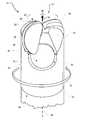
- FIG. 1is a perspective view of a portion of an exemplary drilling apparatus according to at least one embodiment.
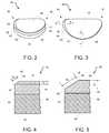
- FIG. 2is a perspective view of an exemplary cutting element according to at least one embodiment.
- FIG. 3is a top view of the exemplary cutting element illustrated in FIG. 3 .
- FIG. 4is a partial cross-sectional view of the exemplary cutting element illustrated in FIG. 3 .
- FIG. 5is a partial cross-sectional view of the exemplary cutting element illustrated in FIG. 3 .
- FIG. 6is a partial cross-sectional view of an exemplary cutting element according to at least one embodiment.
- FIG. 7is a partial cross-sectional view of an exemplary cutting element according to at least one embodiment.
- FIG. 8is a partial cross-sectional view of an exemplary cutting element according to at least one embodiment.
- FIG. 9is a perspective view of an exemplary cutting element according to at least one embodiment.
- FIG. 10is a perspective view of an exemplary cutting element according to at least one embodiment.
- FIG. 11is a perspective view of an exemplary cutting element according to at least one embodiment.
- FIG. 12is a perspective view of an exemplary drill bit that includes the cutting element illustrated in FIG. 10 according to at least one embodiment.
- FIG. 13is a perspective view of an exemplary drill bit that includes the cutting element illustrated in FIG. 11 according to at least one embodiment.
- FIG. 14is a perspective view of an exemplary cutting element according to at least one embodiment.
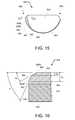
- FIG. 15is a top view of an exemplary cutting element according to at least one embodiment.
- FIG. 16is a partial cross-sectional view of the exemplary cutting element illustrated in FIG. 15 .
- FIG. 17is a perspective view of an exemplary cutting element according to at least one embodiment.
- a drill bitsuch as a roof-bolt drill bit
- a drilling apparatusconfigured to rotate the drill bit relative to a subterranean formation.
- Cutting elements for cutting the subterranean formationmay be mounted to a bit body of the drill bit.
- the word “cutting,” as used in this specification and claims,refers broadly to machining processes, drilling processes, boring processes, or any other material removal process.
- FIG. 1is a perspective view of a portion of an exemplary drilling apparatus 21 according to at least one embodiment.
- Drilling apparatus 21may comprise a drill bit 20 coupled to a drill steel 34 .
- Drill bit 20may represent any type or form of earth-boring or drilling tool, including, for example, a roof-bolt drill bit.
- Drill bit 20may be formed of any material or combination of materials, such as steel or molded tungsten carbide, without limitation.
- drill bit 20may comprise a bit body 22 having a forward end 24 , a rearward end 26 , and a rotational axis 38 .
- At least one cutting element 28may be coupled to bit body 22 .
- a plurality of cutting elements 28may be coupled to forward end 24 of bit body 22 .
- forward portions 40 of cutting elements 28may extend from bit body 22 in axially forward direction 35 along rotational axis 38 .
- forward portions 40 of cutting elements 28may form a cutting tip extending from forward end 24 of bit body 22 in axially forward direction 35 .
- Cutting elements 28may be coupled to bit body 22 using any suitable technique, including, for example, brazing or welding.
- back surfaces of cutting elements 28may be mounted and secured to mounting surfaces on bit body 22 , such as mounting surface 36 shown in FIG. 1 .
- two cutting elements 28may be positioned on bit body 22 circumferentially substantially 180° apart with substantially the same back rake angles and substantially the same side rake angles.
- the at least one cutting elementmay be positioned with a back rake angle of between approximately 5° and approximately 45° and a side rake angle of between approximately 0° and approximately 20°
- an internal passage 30may be defined within bit body 22 .
- Internal passage 30may extend from a rearward opening defined in rearward end 26 of bit body 22 to at least one debris opening 32 defined in a side portion of bit body 22 .
- drill bit 20may be configured for use in dry-drilling environments where cutting debris is removed from a borehole by applying a vacuum to internal passage 30 .
- a vacuum applied to vacuum hole 30may generate suction near debris opening 32 , thereby drawing cutting debris away from the borehole and through opening 32 .
- a vacuum applied to vacuum hole 30may also facilitate cooling of cutting elements 28 and/or other portions of drill bit 20 through convective heat transfer as air and debris are drawn over and around cutting elements 28 .
- one debris opening 32may be defined in bit body 22 for each cutting element 28 .
- two debris openings 32may be defined in bit body 22 , with the two debris openings 32 corresponding to the two respective cutting elements 28 illustrated in FIG. 1 .
- bit body 22may not include a debris opening for removing cutting debris.
- drill bit 20may be configured for use in wet-drilling environments where drilling fluids, such as drilling mud or water, are used to cool drill bit 20 and flush debris away from drill bit 20 and out of a borehole during drilling.
- ports for dispensing drilling fluids into the boreholemay be defined in forward and/or side portions of bit body 22 . Drilling fluids may be conveyed to such ports through one or more internal passages extending through bit body 22 and/or drill steel 34 .
- drill bit 20may be configured to be rotated about rotational axis 38 .
- drill bit 20may be configured to be rotated about rotational axis 38 in rotational direction 37 .
- Drill bit 20may be rotated using a suitable attachment connected to rearward end 26 of bit body 22 .
- drill steel 34may rotate drill bit 20 in rotational direction 37 during drilling of a borehole.
- rearward end 26 of drill bit 20may be coupled to drill steel 34 by, for example, a threaded connection, a pin connection, and/or other suitable coupling.
- Drill steel 34may comprise any suitable type of drilling rod or other suitable connection member configured to connect drill bit 20 to a drilling apparatus, without limitation.
- drill steel 34may comprise a substantially elongated shaft (e.g., a cylindrical shaft) having coupling surfaces corresponding to surfaces defined within drill bit 20 .
- drill steel 34may comprise a hexagonal and/or threaded periphery corresponding to a hexagonal and/or threaded interior surface defined within drill bit 20 .
- drill steel 34may comprise a pin connector corresponding to a pin hole and/or a recess defined within drill bit 20 .
- forces and/or torquemay be applied by a drilling motor to drill bit 20 via drill steel 34 , causing drill bit 20 to be forced against a subterranean formation in both rotational direction 37 and forward direction 35 .
- cutting elements 28may contact and cut into the subterranean formation, removing rock material from the formation in the form of rock cuttings and/or other debris.
- cutting debris removed by cutting elements 28may be drawn through internal passage 30 defined in bit body 22 by a vacuum applied to drill bit 20 .
- drill steel 34may comprise a hollow rod and a vacuum may be applied to a rearward end of drill steel 34 by a vacuum source. Cutting debris may be drawn by the vacuum through drill bit 20 and drill steel 34 toward the vacuum source.
- FIG. 2-8illustrate exemplary cutting elements 28 that may be coupled to exemplary bit body 22 in FIG. 1 .
- FIG. 2is a perspective view of a cutting element 28 and
- FIG. 3is a top view of cutting element 28 .
- cutting element 28may comprise a layer or table 44 affixed to or formed upon a substrate 46 .
- Table 44may be formed of any material or combination of materials suitable for cutting subterranean formations, including, for example, a superhard or superabrasive material such as polycrystalline diamond (PCD).
- PCDpolycrystalline diamond
- the word “superhard,” as used herein,refers to any material having a hardness that is at least equal to a hardness of tungsten carbide.
- substrate 46may comprise any material or combination of materials capable of adequately supporting a superabrasive material during drilling of a subterranean formation, including, for example, cemented tungsten carbide.
- cutting element 28may comprise a table 44 comprising polycrystalline diamond bonded to a substrate 46 comprising cobalt-cemented tungsten carbide.
- a catalyst materiale.g., cobalt or nickel
- a catalyst materialmay be removed from at least a portion of table 44 using any suitable technique, such as, for example, acid leaching.
- table 44may formed to a thickness of at least about 0.030 inches.
- table 44may have a thickness of between about 0.030 inches and about 0.120 inches. In additional embodiments, table 44 may have a thickness less than 0.030 inches.
- cutting element 28may also comprise a cutting face 48 formed by table 44 , a peripheral surface 50 formed by table 44 and substrate 46 , and a back surface 54 formed by substrate 46 .
- cutting face 48may be substantially planar and peripheral surface 50 may comprise a partial-cylindrical and/or otherwise arcuate surface that is optionally perpendicular to cutting face 48 .
- Back surface 54may be, in some embodiments, substantially parallel to cutting face 48 .
- Cutting face 48 and peripheral surface 50may be formed in any suitable shape, without limitation.
- cutting face 48may have a substantially arcuate periphery. In some embodiments, as illustrated in FIGS.
- cutting face 48may have a substantially semi-circular or partial-circular periphery having one or more rounded corner portions.
- cutting element 28may include a forward portion 40 that is configured to extend from bit body 22 of drill bit 20 in forward direction 35 .
- Cutting element 28may also include a rearward portion 42 located opposite forward portion 40 .
- cutting element 28may comprise a peripherally extending chamfer 56 formed along at least a portion of a periphery of table 44 between cutting face 48 and peripheral surface 50 , as illustrated in FIGS. 1-3 . Additionally, cutting element 28 may comprise a chamfer region 58 located on forward portion 40 of cutting element 28 . As shown in FIGS. 1-3 , peripherally extending chamfer 56 may extend from chamfer region 58 toward rearward portion 42 of cutting element 28 . According to at least one embodiment, at least portions of peripherally extending chamfer 56 and/or chamfer region 58 may comprise a substantially planar surface extending between cutting face 48 and peripheral surface 50 .
- Table 44may also include any other suitable surface shape extending between cutting face 48 and peripheral surface 50 , including, without limitation, an arcuate surface, a radius, a sharp edge, and/or a honed edge.
- Chamfer 56may be configured to contact and/or cut a solid material, such as a subterranean formation, as drill bit 20 is rotated and forced against the solid material.
- cutting edgeor its variants refers to an edge portion of cutting element 28 that is exposed to and/or in contact with a formation or material being cut during drilling as drill bit 20 is directed in forward direction 35 and rotated about rotational axis 38 in rotational direction 37 .
- cutting element 28may comprise one or more cutting edges, such as a portion of first edge 60 and/or a portion of second edge 62 .
- First edge 60 and/or second edge 62may define at least a portion of peripherally extending chamfer 56 and/or chamfer region 58 and may be configured to be exposed to and/or in contact with a material being cut during drilling.
- FIG. 4is a partial cross-sectional view of a portion of cutting element 28 taken along line I-I shown in FIG. 3 .
- FIG. 4shows a portion of cutting element 28 that includes peripherally extending chamfer 56 .
- FIG. 5is a partial cross-sectional view of a portion of cutting element 28 taken along line II-II shown in FIG. 3 .
- FIG. 5shows a portion of cutting element 28 that includes chamfer region 58 located on forward portion 40 of cutting element 28 .
- chamfer region 58may have a greater width W 2 than width W 1 of peripherally extending chamfer 56 as measured between first edge 60 and second edge 62 .
- widthused in reference to a chamfer or chamfer region refers to the shortest distance between two edges defining the chamfer or chamfer region measured at a selected location on the chamfer or chamfer region.
- a width of a portion of peripherally extending chamfer 56 and/or chamfer region 58 as measured between first edge 60 and second edge 62may comprise the shortest distance between first edge 60 and second edge 62 extending through a selected location on peripherally extending chamfer 56 and/or chamfer region 58 .
- the width W 2 of the portion of chamfer region 58 shown in FIG. 5may be greater than the width W 1 of the portion of peripherally extending chamfer 56 shown in FIG. 4 .
- a width W 2 of chamfer region 58 on forward portion 40may be greater than twice the width W 1 of peripherally extending chamfer 56 .
- a width W 2 of chamfer region 58may be greater than twice a maximum width W 1 of peripherally extending chamfer 56 .
- peripherally extending chamfer 56may be substantially the same.
- peripherally extending chamfer 56may have a substantially constant width between first edge 60 and second edge 62 along the length of peripherally extending chamfer 56 from chamfer region 58 to rearward end 42 .
- peripherally extending chamfer 56may vary in width at various locations along its length, without limitation.
- chamfer region 58may vary in width at different locations along its length. For example, as illustrated in FIGS. 2 and 3 , chamfer region 58 may vary in width as it extends from peripherally extending chamfer 56 .
- chamfer region 58may increase in width as it extends from peripherally extending chamfer 56 . In one embodiment, chamfer region 58 may increase in width to a maximum, and then may decrease in width as it extends from peripherally extending chamfer 56 . According to additional embodiments, chamfer region 58 may be substantially constant in width as it extends from peripherally extending chamfer 56 .
- peripherally extending chamfer 56 and chamfer region 58may be selected so as to optimize the cutting performance and/or structural stability of cutting elements 28 .
- the smaller width of peripherally extending chamfer 56may optimize the cutting efficiency of cutting element 28 .
- peripherally extending chamfer 56may be oriented on a drill bit (e.g., drill bit 20 illustrated in FIG. 1 ) so that at least a portion of peripherally extending chamfer 56 is in contact with a subterranean formation being drilled for a selected revolutions per minute (RPM) and rate of penetration (ROP).
- RPMrevolutions per minute
- ROPrate of penetration
- the smaller width of peripherally extending chamfer 56may facilitate aggressive removal of a solid material, such as rock material, leading to increased drilling efficiency and rate of penetration of cutting element 28 .
- the larger width of chamfer region 58may increase the durability of cutting element 28 , thereby preventing spalling, chipping, and/or partial fracturing of forward end 40 during drilling.
- Chamfer regions 58 of cutting elements 28may be oriented so that at least a portion of each chamfer region 58 is in contact with a subterranean formation being drilled for a selected RPM and ROP.
- forward ends 40 of cutting elements 28may experience significant stresses in comparison to other portions of cutting elements 28 due to the significant thrust and tensile loads applied to forward ends 40 .
- drill bit 20may be forced against a subterranean formation in forward direction 35 .
- forward ends 40 of cutting elements 28 mounted to bit body 22may be subjected to greater stresses than other portions of cutting elements 28
- chamfer regions 58 on forward ends 40 of cutting elements 28may be subjected to greater stresses than peripherally extending chamfers 56 .
- forward ends 40 of cutting elements 28may be subjected to greater stresses due to the locations of forward ends 40 to a rotational axis 38 of drill bit 20 during drilling.
- forward ends 40 of cutting elements 20may form at least a portion of cutting tip 39 centered about rotational axis 38 .
- Forward ends 40may be disposed in closer proximity to rotational axis 38 than other portions of cutting elements 28 that are in contact with a subterranean formation during drilling. Because forward ends 40 are positioned closer to rotational axis 38 than other portions of cutting elements 28 , forward ends 40 may travel shorter distances per revolution of drill bit 20 than other portions of cutting elements 28 that are located a greater distance from rotational axis 38 .
- chamfer regions 58 on forward ends 40 of cutting elements 28may travel shorter distances per revolution of drill bit 20 than portions of peripherally extending chamfers 56 that are in contact with a subterranean formation during drilling as drill bit 20 is directed in forward direction 35 and rotated about rotational axis 38 in rotational direction 37 . Because the distances traveled by forward ends 40 are less than the distances traveled by the portions of peripherally extending chamfers 56 at an effective “depth of cut” (i.e., the distance the cutting edge is buried into the formation being drilled), a greater amount of force may be built up in chamfer regions 58 of cutting elements 28 in comparison with peripherally extending chamfers 56 .
- chamfer region 58 on forward end 40 of each cutting element 28may enable distribution of the higher stresses over a greater surface area in comparison with peripherally extending chamfer 56 . Accordingly, chamfer region 58 may prevent spalling, chipping, and/or partial fracturing of cutting element 28 due to the pressure of excessive stresses in forward end 40 . According to at least one embodiment, chamfer region 58 may vary along its length from greater widths at more forward locations to lesser widths at more rearward locations. For example, as illustrated in FIGS. 1-3 , chamfer region 58 may narrow from a greater width at a forward location to approximately the same width as peripherally extending chamfer 56 at a region adjacent to peripherally extending chamfer 56 .
- chamfer region 58may provide the greatest surface area at a forwardmost region of cutting element 28 and may provide decreased surface areas at regions of cutting element 28 that are located rearward therefrom. Accordingly, chamfer region 58 may provide a greater amount of structural stability at the forward region and may provide increasing cutting efficiency as chamfer region 58 narrows between the forward region and peripherally extending chamfer 56 .
- Peripherally extending chamfer 56 and/or chamfer region 58may be formed by any suitable process, such as grinding, lapping, and/or machining (e.g., electro-discharge machining “EDM”), without limitation.
- peripherally extending chamfer 56 and/or chamfer region 58may be formed by grinding cutting element 28 along an oblique path with respect to cutting face 48 and/or peripheral surface 50 of cutting element 28 .
- peripherally extending chamfer 56 and/or chamfer region 58may also be formed by molding such features on cutting element 28 during an HPHT sintering process used to form cutting element 28 .
- Peripherally extending chamfer 56 and chamfer region 58may be formed to different geometries using any suitable technique.
- the depth and/or angle of peripherally extending chamfer 56 and/or chamfer region 58may be selected so as to obtain a desired geometry.
- the depth D 1 or D 2 of peripherally extending chamfer 56 and/or chamfer region 58 with respect to cutting face 48 and/or peripheral surface 50may be selected so as to obtain a desired width and angle for peripherally extending chamfer 56 and chamfer region 58 .
- FIG. 4 and 5the depth D 1 or D 2 of peripherally extending chamfer 56 and/or chamfer region 58 with respect to cutting face 48 and/or peripheral surface 50 may be selected so as to obtain a desired width and angle for peripherally extending chamfer 56 and chamfer region 58 .
- peripherally extending chamfer 56may be formed so that second edge 62 defining a portion of peripherally extending chamfer 56 is located at a depth D 1 with respect to cutting face 48 . Accordingly, peripherally extending chamfer 56 may have a width W 1 as measured between first edge 60 and the second edge 62 . Additionally, as shown in FIG. 5 , chamfer region 58 may be formed so that second edge 62 defining chamfer region 58 is located at a depth D 2 with respect to cutting face 48 . Depth D 2 may be greater than depth D 1 . Accordingly, a width W 2 of chamfer region 58 , as measured between first edge 60 and the second edge 62 , may be greater than the width W 1 of peripherally extending chamfer 56 .
- the angle of peripherally extending chamfer 56 and/or chamfer region 58 with respect to cutting face 48 and/or peripheral surface 50may be selected so as to obtain a desired width for peripherally extending chamfer 56 and/or chamfer region 58 .
- peripherally extending chamfer 56may be formed at an angle ⁇ 1 with respect to cutting face 48 .
- peripherally extending chamfer 56may have a first width (e.g., width W 1 illustrated in FIG. 4 ) as measured between first edge 60 and the second edge 62 .
- a first widthe.g., width W 1 illustrated in FIG. 4
- chamfer region 58may be formed at an angle ⁇ 2 that is less than angle ⁇ 1 with respect to cutting face 48 .
- a second width (e.g., width W 2 illustrated in FIG. 5 ) of chamfer region 58may be greater than the first width of peripherally extending chamfer 56 , such as, for example, when angle ⁇ 2 is less than angle ⁇ 1 with respect to cutting face 48 and portions of second edge 62 adjacent the first width are located at substantially the same depth with respect to cutting face 48 as portions of second edge 62 adjacent the second width.
- angle ⁇ 2may be greater than or equal to angle ⁇ 1 . More generally, angles ⁇ 1 and ⁇ 2 , as well as widths W 1 and W 2 and depths D 1 and D 2 may be selected as desired.
- peripherally extending chamfer 56 and/or chamfer region 58may be formed on table 44 of cutting element 28 .
- peripherally extending chamfer 56 , chamfer region 58 , and a portion of peripheral surface 50 extending between second edge 62 and substrate 46may be formed on table 44 .
- peripherally extending chamfer 56 and/or chamfer region 58may be formed on both table 44 and substrate 46 .
- chamfer region 58may extend from first edge 60 formed on table 44 to second edge 62 formed on substrate 46 of cutting element 28 .
- FIG. 9-11illustrate various exemplary cutting elements that may be coupled to bit bodies of drill bits according to various embodiments.
- FIG. 9is a perspective view of an exemplary cutting element 128 according to at least one embodiment.
- cutting element 128may comprise a table 144 affixed to or formed upon a substrate 146 .
- Cutting element 128may also comprise a cutting face 148 formed by table 144 , a peripheral surface 150 formed by table 144 and substrate 146 , and a back surface 154 formed by substrate 146 .
- Cutting face 148 and peripheral surface 150may be formed in any suitable shape, without limitation.
- cutting face 148may have a substantially arcuate periphery. In some embodiments, as illustrated in FIG.
- peripheral surface 150may comprise a substantially cylindrical surface.
- Cutting element 128may include a forward portion 140 that is configured to extend from a bit body of a drill bit (e.g., bit body 222 of drill bit 220 illustrated in FIG. 12 ). Cutting element 128 may also include a rearward portion 142 located opposite forward portion 140 .
- Cutting element 128may further comprise a peripherally extending chamfer 156 formed along at least a portion of a periphery of table 144 between cutting face 148 and peripheral surface 150 . Additionally, cutting element 128 may comprise a chamfer region 158 located at forward portion 140 of the cutting element. Peripherally extending chamfer 156 may extend from chamfer region 158 toward rearward portion 142 of cutting element 128 , as shown in FIG. 9 . In some embodiments, cutting element 128 may comprise one or more cutting edges, such as portions of a first edge 160 and/or a second edge 162 . First edge 160 and/or second edge 162 may define at least a portion of peripherally extending chamfer 156 and/or chamfer region 158 .
- FIG. 10is a perspective view of an exemplary cutting element 228 according to some embodiments.
- cutting element 228may comprise a table 244 affixed to or formed upon a substrate 246 .
- Cutting element 228may also comprise a cutting face 248 formed by table 244 , a peripheral surface 250 formed by table 244 and substrate 246 , and a back surface 254 formed by substrate 246 .
- Cutting face 248 and peripheral surface 250may be formed in any suitable shape, without limitation.
- cutting face 248may have a substantially arcuate periphery.
- peripheral surface 250may comprise a substantially cylindrical surface.
- Cutting element 228may include a forward portion 240 that is configured to extend from a bit body of a drill bit (e.g., bit body 222 of drill bit 220 illustrated in FIG. 12 ). Cutting element 228 may also include a rearward portion 242 located opposite forward portion 240 .
- Cutting element 228may comprise a first peripherally extending chamfer 256 A and a second peripherally extending chamfer 256 B formed along at least a portion of a periphery of table 244 between cutting face 248 and peripheral surface 250 . Additionally, cutting element 228 may comprise a first chamfer region 258 A located at forward portion 240 of cutting element 228 and a second chamfer region 258 B located at rearward portion 242 . In at least one embodiment, cutting element 228 may comprise a substantially symmetrical periphery about a plane extending through cutting element 228 . For example, a border 247 may define a plane extending through cutting element 228 .
- first chamfer region 258 Amay comprise substantially the same shape as second chamfer region 258 B and/or first peripherally extending chamfer 256 A may comprise substantially the same shape as second peripherally extending chamfer 256 B.
- cutting element 228may comprise one or more cutting edges, such as portions of a first edge 260 and/or a second edge 262 .
- First edge 260 and/or second edge 262may define at least a portion of first peripherally extending chamfer 256 A, second peripherally extending chamfer 256 B, first chamfer region 258 A, and/or second chamfer region 258 B.
- cutting element 228may be configured to be removed and repositioned when a portion of cutting element 228 , such as forward portion 240 , becomes worn and/or damaged from drilling.
- cutting element 228may be initially oriented on a bit body (e.g. bit body 222 illustrated in FIG. 12 ) so that so that first chamfer region 258 A on forward portion 240 extends from the bit body in a forward direction 235 . Accordingly, portions of first chamfer region 258 A and first peripherally extending chamfer 256 A may be exposed to a subterranean formation during drilling.
- Cutting element 228may subsequently be removed and remounted to the bit body so that second chamfer region 258 B and second peripherally extending chamfer 256 B are exposed to a subterranean formation during subsequent drilling.
- cutting element 228may be removed and repositioned on the bit body when first chamfer region 258 A and/or first peripherally extending chamfer 256 A become worn and/or damaged.
- the region of cutting element 228 that includes second chamfer region 258 Bbecomes the forward portion (e.g., forward portion 240 ) of cutting element 228 .
- cutting element 228may continue to be used in drilling operations even after a portion of cutting element 228 , such as first chamfer region 258 A and/or first peripherally extending chamfer 256 A, becomes worn and/or damaged.
- FIG. 11is a perspective view of an exemplary cutting element 328 according to some embodiments.
- cutting element 328may comprise a table 344 affixed to or formed upon a substrate 346 .
- Cutting element 328may also comprise a cutting face 348 formed by table 344 , a peripheral surface 350 formed by table 344 and substrate 346 , and a back surface 354 formed by substrate 346 .
- Cutting face 348 and peripheral surface 350may be formed in any suitable shape, without limitation.
- cutting face 348may have a substantially arcuate periphery.
- peripheral surface 350may comprise a partial-cylindrical surface. For example, as illustrated in FIG.
- peripheral surface 350may comprise two-partial cylindrical surfaces with arcuate portions extending between the partial-cylindrical surfaces.
- An example of a drill bit incorporating superabrasive cutting elements having a peripheral surface as illustrated in FIG. 11may be found in U.S. Pat. No. 5,429,199, the disclosure of which is incorporated herein, in its entirety, by this reference.
- Cutting element 328may include a forward portion 340 that is configured to extend from a bit body of a drill bit (e.g., bit body 322 of drill bit 320 illustrated in FIG. 13 ).
- Cutting element 328may also include a rearward portion 342 located opposite forward portion 340 .
- Cutting element 328may comprise a first peripherally extending chamfer 356 A and a second peripherally extending chamfer 356 B formed along at least a portion of a periphery of table 344 between cutting face 348 and peripheral surface 350 . Additionally, cutting element 328 may comprise a first chamfer region 358 A located at forward portion 340 of the cutting element and a second chamfer region 358 B located at rearward portion 342 . In at least one embodiment, first chamfer region 358 A may comprise substantially the same shape as second chamfer region 358 B and first peripherally extending chamfer 356 A may comprise substantially the same shape as second peripherally extending chamfer 356 B.
- cutting element 328may comprise one or more cutting edges, such as portions of a first edge 360 and/or a second edge 362 .
- First edge 360 and/or second edge 362may define at least a portion of first peripherally extending chamfer 356 A, second peripherally extending chamfer 356 B, first chamfer region 358 A, and/or second chamfer region 358 B.
- cutting element 328may be configured to be removed and repositioned when a portion of cutting element 328 , such as forward portion 340 , becomes worn and/or damaged from drilling.
- cutting element 328may be removed and repositioned on the bit body when first chamfer region 358 A and/or first peripherally extending chamfer 356 A become worn and/or damaged.
- the region of cutting element 328 that includes second chamfer region 358 Bbecomes the forward portion (e.g., forward portion 340 ) of cutting element 328 .
- cutting element 328may continue to be used in drilling operations even after a portion of cutting element 328 , such as first chamfer region 358 A and/or first peripherally extending chamfer 356 A, becomes worn and/or damaged.
- FIGS. 12 and 13illustrate exemplary drill bits according to various embodiments.
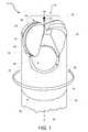
- FIG. 12is a perspective view of an exemplary drill bit 220 that includes the exemplary cutting element illustrated in FIG. 10 .
- drill bit 220may comprise a bit body 222 having a forward end 224 , a rearward end 226 , and a rotational axis 238 .
- At least one cutting element 228may be coupled to bit body 222 .
- a plurality of cutting elements 228may be coupled to forward end 224 of bit body 222 .
- two cutting elements 228may be positioned on bit body 222 circumferentially substantially 180° apart with substantially the same back rake angles and substantially the same side rake angles.
- an internal passage 230may be defined within bit body 222 .
- Internal passage 230may extend from a rearward opening defined in rearward end 226 of bit body 222 to at least one debris opening 232 defined in a side portion of bit body 222 .
- a forward portion 240 of cutting element 228may extend from bit body 222 in an axially forward direction 235 along rotational axis 238 .
- cutting element 228may be oriented on bit body 222 so that first chamfer region 258 A on forward portion 240 extends from bit body 222 in axially forward direction 235 . Accordingly, portions of first chamfer region 258 A and first peripherally extending chamfer 256 A may be exposed to a subterranean formation during drilling as drill bit 220 is directed in forward direction 235 and rotated about rotational axis 238 in rotational direction 237 .
- cutting element 228may be removed and remounted to bit body 222 such that second chamfer region 258 B extends from bit body 222 in axially forward direction 235 and such that second chamfer region 258 B and second peripherally extending chamfer 256 B are exposed to a subterranean formation during subsequent drilling as drill bit 220 is directed in forward direction 235 and rotated about rotational axis 238 in rotational direction 237 .
- FIG. 13is a perspective view of an exemplary drill bit 320 that includes the exemplary cutting element illustrated in FIG. 11 .
- drill bit 320may comprise a bit body 322 having a forward end 324 , a rearward end 326 , and a rotational axis 338 .
- At least one cutting element 328may be coupled to bit body 322 .
- a plurality of cutting elements 328may be coupled to forward end 324 of bit body 322 .
- two cutting elements 328may be positioned on bit body 322 circumferentially substantially 180° apart with substantially the same back rake angles and substantially the same side rake angles.
- FIG. 14is a perspective view of an exemplary cutting element 428 according to at least one embodiment.
- cutting element 428may comprise a table 444 affixed to or formed upon a substrate 446 .
- Cutting element 428may also comprise a cutting face 448 formed by table 444 , a peripheral surface 450 formed by table 444 and substrate 446 , and a back surface 454 formed by substrate 446 .
- Cutting face 448 and peripheral surface 450may be formed in any suitable shape, without limitation.
- cutting face 448may have a substantially arcuate periphery.
- Cutting element 428may include a forward portion 440 that is configured to extend from a bit body of a drill bit (e.g., bit body 22 of drill bit 20 illustrated in FIG. 1 ). Cutting element 428 may also include a rearward portion 442 located opposite forward portion 440 .
- Cutting element 428may further comprise a peripherally extending chamfer 456 formed along at least a portion of a periphery of table 444 between cutting face 448 and peripheral surface 450 . Additionally, cutting element 428 may comprise a plurality of chamfer regions located at forward portion 440 of the cutting element. For example, cutting element 428 may comprise a first chamfer region 458 A and a second chamfer region 458 B disposed at forward portion 440 . Peripherally extending chamfer 456 may extend from first chamfer region 458 A toward rearward portion 442 of cutting element 428 , as shown in FIG. 14 . Additionally, first chamfer region 458 A may extend from second chamfer region 458 B toward peripherally extending chamfer 456 . In some embodiments, first chamfer region 458 A and second chamfer region 458 B may have varying widths.
- FIGS. 15 and 16show an exemplary cutting element 528 according to at least one embodiment.
- FIG. 16is a partial cross-sectional view of a portion of cutting element 528 taken along line III-III shown in FIG. 15 .
- cutting element 528may comprise a table 544 affixed to or formed upon a substrate 546 .
- Cutting element 528may also comprise a cutting face 548 formed by table 544 , a peripheral surface 550 formed by table 544 and substrate 546 , and a back surface 554 formed by substrate 546 .
- Cutting face 548 and peripheral surface 550may be formed in any suitable shape, without limitation. In at least one embodiment, cutting face 548 may have a substantially arcuate periphery.
- Cutting element 528may include a forward portion 540 that is configured to extend from a bit body of a drill bit (e.g., bit body 22 of drill bit 20 illustrated in FIG. 1 ). Cutting element 528 may also include a rearward portion 542 located opposite forward portion 540 .
- Cutting element 528may further comprise a peripherally extending chamfer 556 formed along at least a portion of a periphery of table 544 between cutting face 548 and peripheral surface 550 . Additionally, cutting element 528 may comprise at least one chamfer region located at forward portion 540 of the cutting element. For example, cutting element 528 may comprise a first chamfer region 558 A and a second chamfer region 558 B disposed at forward portion 540 . Peripherally extending chamfer 556 may extend from first chamfer region 558 A and/or second chamfer region 558 B toward rearward portion 542 of cutting element 528 , as shown in FIG. 15 .
- first chamfer region 558 A and second chamfer region 558 Bmay have varying widths. As illustrated in FIGS. 15 and 16 , first chamfer region 558 A may be located adjacent cutting face 548 and second chamfer region 558 B may be located adjacent peripheral surface 550 . According to at least one embodiment, first chamfer region 558 A may extend from cutting face 548 to second chamfer region 558 B, and second chamfer region 558 B may extend from first chamfer region 558 A to peripheral surface 550 .
- cutting element 528may comprise one or more cutting edges, such as portions of a first edge 560 , a second edge 562 , a third edge 564 , and/or a fourth edge 566 .
- First edge 560 , second edge 562 , third edge 564 , and/or fourth edge 566may define at least a portion of peripherally extending chamfer 556 , first chamfer region 558 A, and/or second chamfer region 558 B.
- first edge 560 and second edge 562may define at least a portion of peripherally extending chamfer 556 .
- third edge 564 and fourth edge 566may define at least a portion of first chamfer region 558 A, as shown in FIGS. 15 and 16 .
- second edge 562 and fourth edge 566may define at least a portion of second chamfer region 558 B.
- First chamfer region 558 A and second chamfer region 558 Bmay be formed to different geometries using any suitable technique.
- the depths and/or angles of first chamfer region 558 A and/or second chamfer region 558 Bmay be selected so as to obtain a desired geometry.
- a depth D 3 of a portion of first chamfer region 558 A and/or a depth D 4 of a portion of second chamfer region 558 B with respect to cutting face 548may be selected so as to obtain a desired width and angle for first chamfer region 558 A and second chamfer region 558 B.
- FIG. 16a depth D 3 of a portion of first chamfer region 558 A and/or a depth D 4 of a portion of second chamfer region 558 B with respect to cutting face 548 may be selected so as to obtain a desired width and angle for first chamfer region 558 A and second chamfer region 558 B.
- first chamfer region 558 A and second chamfer region 558 B with respect to cutting face 548 and/or peripheral surface 550may be selected so as to obtain desired widths for first chamfer region 558 A and second chamfer region 558 B. According to some embodiments, the angles of first chamfer region 558 A and second chamfer region 558 B with respect to cutting face 548 and/or peripheral surface 550 may be different.
- First chamfer region 558 A and/or second chamfer region 558 Bmay exhibit average widths that individually exceed an average width of peripherally extending chamfer 556 .
- first chamfer region 558 A and/or second chamfer region 558 Bmay exhibit average widths that are individually less than an average width of peripherally extending chamfer 556 and a combined average width that exceeds an average width of peripherally extending chamfer 556 .
- First chamfer region 558 Amay exhibit substantially the same average width or a different average width than second chamfer region 558 B.
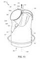
- FIG. 17is a perspective view of an exemplary cutting element 628 according to at least one embodiment.
- cutting element 628may comprise a table 644 affixed to or formed upon a substrate 646 .
- Cutting element 628may also comprise a cutting face 648 formed by table 644 , a peripheral surface 650 formed by table 644 and substrate 646 , and a back surface 654 formed by substrate 646 .
- Cutting face 648 and peripheral surface 650may be formed in any suitable shape, without limitation.
- cutting face 648may have a substantially arcuate periphery.
- Cutting element 628may include a forward portion 640 that is configured to extend from a bit body of a drill bit (e.g., bit body 22 of drill bit 20 illustrated in FIG. 1 ). Cutting element 628 may also include a rearward portion 642 located opposite forward portion 640 .
- Cutting element 628may further comprise a peripherally extending edge 668 formed along at least a portion of a periphery of table 644 between cutting face 648 and peripheral surface 650 . Additionally, cutting element 628 may comprise a chamfer region 658 located at forward portion 640 of the cutting element. Peripherally extending edge 668 may extend from chamfer region 658 toward rearward portion 642 of cutting element 628 , as shown in FIG. 17 . In at least one embodiment, cutting element 628 may comprise one or more cutting edges, such as a portion of a first edge 660 , a portion of a second edge 662 , and/or a portion of peripherally extending edge 668 . First edge 660 and/or second edge 662 may define at least a portion of chamfer region 658 .
Landscapes
- Engineering & Computer Science (AREA)
- Mining & Mineral Resources (AREA)
- Life Sciences & Earth Sciences (AREA)
- Geology (AREA)
- Mechanical Engineering (AREA)
- Chemical & Material Sciences (AREA)
- General Life Sciences & Earth Sciences (AREA)
- Geochemistry & Mineralogy (AREA)
- Physics & Mathematics (AREA)
- Environmental & Geological Engineering (AREA)
- Fluid Mechanics (AREA)
- Structural Engineering (AREA)
- Ceramic Engineering (AREA)
- Inorganic Chemistry (AREA)
- Drilling Tools (AREA)
- Earth Drilling (AREA)
Abstract
Description
Claims (20)
Priority Applications (6)
| Application Number | Priority Date | Filing Date | Title |
|---|---|---|---|
| US12/980,217US8899356B2 (en) | 2010-12-28 | 2010-12-28 | Drill bits, cutting elements for drill bits, and drilling apparatuses including the same |
| AU2011352789AAU2011352789B2 (en) | 2010-12-28 | 2011-12-20 | Drill bits, cutting elements for drill bits, and drilling apparatuses including the same |
| PCT/US2011/066314WO2012092042A1 (en) | 2010-12-28 | 2011-12-20 | Drill bits, cutting elements for drill bits, and drilling apparatuses including the same |
| CA2822817ACA2822817C (en) | 2010-12-28 | 2011-12-20 | Drill bits, cutting elements for drill bits, and drilling apparatuses including the same |
| EP11852677.1AEP2659083B1 (en) | 2010-12-28 | 2011-12-20 | Drill bits, cutting elements for drill bits, and drilling apparatuses including the same |
| US14/536,559US9415447B2 (en) | 2010-12-28 | 2014-11-07 | Drill bits, cutting elements for drill bits, and drilling apparatuses including the same |
Applications Claiming Priority (1)
| Application Number | Priority Date | Filing Date | Title |
|---|---|---|---|
| US12/980,217US8899356B2 (en) | 2010-12-28 | 2010-12-28 | Drill bits, cutting elements for drill bits, and drilling apparatuses including the same |
Related Child Applications (1)
| Application Number | Title | Priority Date | Filing Date |
|---|---|---|---|
| US14/536,559ContinuationUS9415447B2 (en) | 2010-12-28 | 2014-11-07 | Drill bits, cutting elements for drill bits, and drilling apparatuses including the same |
Publications (2)
| Publication Number | Publication Date |
|---|---|
| US20120160573A1 US20120160573A1 (en) | 2012-06-28 |
| US8899356B2true US8899356B2 (en) | 2014-12-02 |
Family
ID=46315314
Family Applications (2)
| Application Number | Title | Priority Date | Filing Date |
|---|---|---|---|
| US12/980,217Active2033-04-24US8899356B2 (en) | 2010-12-28 | 2010-12-28 | Drill bits, cutting elements for drill bits, and drilling apparatuses including the same |
| US14/536,559ActiveUS9415447B2 (en) | 2010-12-28 | 2014-11-07 | Drill bits, cutting elements for drill bits, and drilling apparatuses including the same |
Family Applications After (1)
| Application Number | Title | Priority Date | Filing Date |
|---|---|---|---|
| US14/536,559ActiveUS9415447B2 (en) | 2010-12-28 | 2014-11-07 | Drill bits, cutting elements for drill bits, and drilling apparatuses including the same |
Country Status (5)
| Country | Link |
|---|---|
| US (2) | US8899356B2 (en) |
| EP (1) | EP2659083B1 (en) |
| AU (1) | AU2011352789B2 (en) |
| CA (1) | CA2822817C (en) |
| WO (1) | WO2012092042A1 (en) |
Cited By (2)
| Publication number | Priority date | Publication date | Assignee | Title |
|---|---|---|---|---|
| US20130192902A1 (en)* | 2012-01-30 | 2013-08-01 | Diamond Innovations Inc. | Drill Bit |
| US20150117972A1 (en)* | 2013-10-31 | 2015-04-30 | Union Tool Co. | Hard-coated cutting tool |
Families Citing this family (12)
| Publication number | Priority date | Publication date | Assignee | Title |
|---|---|---|---|---|
| US8800692B2 (en) | 2009-10-02 | 2014-08-12 | Baker Hughes Incorporated | Cutting elements configured to generate shear lips during use in cutting, earth-boring tools including such cutting elements, and methods of forming and using such cutting elements and earth-boring tools |
| US8899356B2 (en)* | 2010-12-28 | 2014-12-02 | Dover Bmcs Acquisition Corporation | Drill bits, cutting elements for drill bits, and drilling apparatuses including the same |
| US9650837B2 (en)* | 2011-04-22 | 2017-05-16 | Baker Hughes Incorporated | Multi-chamfer cutting elements having a shaped cutting face and earth-boring tools including such cutting elements |
| US10323514B2 (en) | 2013-05-16 | 2019-06-18 | Us Synthetic Corporation | Shear cutter pick milling system |
| EP2997223B1 (en) | 2013-05-16 | 2019-03-20 | US Synthetic Corporation | Road-removal system employing polycrystalline diamond compacts |
| US10414069B2 (en) | 2014-04-30 | 2019-09-17 | Us Synthetic Corporation | Cutting tool assemblies including superhard working surfaces, material-removing machines including cutting tool assemblies, and methods of use |
| US10408057B1 (en)* | 2014-07-29 | 2019-09-10 | Apergy Bmcs Acquisition Corporation | Material-removal systems, cutting tools therefor, and related methods |
| US10648330B1 (en) | 2015-09-25 | 2020-05-12 | Us Synthetic Corporation | Cutting tool assemblies including superhard working surfaces, cutting tool mounting assemblies, material-removing machines including the same, and methods of use |
| USD911399S1 (en) | 2018-12-06 | 2021-02-23 | Halliburton Energy Services, Inc. | Innermost cutter for a fixed-cutter drill bit |
| CN111566308A (en) | 2018-12-06 | 2020-08-21 | 哈利伯顿能源服务公司 | Inside cutter for well drilling |
| WO2021142188A1 (en) | 2020-01-09 | 2021-07-15 | Schlumberger Technology Corporation | Cutting element with nonplanar face to improve cutting efficiency and durability |
| USD1012131S1 (en) | 2022-03-03 | 2024-01-23 | Kennametal Inc. | Roof bit |
Citations (78)
| Publication number | Priority date | Publication date | Assignee | Title |
|---|---|---|---|---|
| US3132908A (en) | 1962-04-02 | 1964-05-12 | Carrier Corp | Thrust bearing construction |
| US3311431A (en) | 1964-08-07 | 1967-03-28 | Irving W Hilliard | Temperature compensating bearing assembly |
| US3371970A (en) | 1965-07-08 | 1968-03-05 | Uster Spindel Motoren Maschf | Mounting for high-speed vertical shafts |
| US3442342A (en) | 1967-07-06 | 1969-05-06 | Hughes Tool Co | Specially shaped inserts for compact rock bits,and rolling cutters and rock bits using such inserts |
| US3542441A (en) | 1968-03-28 | 1970-11-24 | Westinghouse Electric Corp | Controlled clearance self-aligning bearing |
| US3625327A (en) | 1969-02-03 | 1971-12-07 | Ransome & Morles Bearing Co Lt | Clutch control bearings |
| US3745623A (en) | 1971-12-27 | 1973-07-17 | Gen Electric | Diamond tools for machining |
| US3858668A (en) | 1971-10-15 | 1975-01-07 | Constuctions Electr Et Mecaniq | Stop arrangement for drill turbines |
| US3858669A (en) | 1973-10-04 | 1975-01-07 | Texas Dynamatics | Drilling apparatus |
| US4129343A (en) | 1976-10-22 | 1978-12-12 | Nadella | Unitary self-aligning bearing assembly |
| WO1980001939A1 (en) | 1979-03-05 | 1980-09-18 | Dana Corp | Center bearing bracket |
| US4226485A (en) | 1977-10-17 | 1980-10-07 | F. Jos. Lamb Company | Bearing assembly with thermal adaptor |
| US4240683A (en) | 1979-01-12 | 1980-12-23 | Smith International, Inc. | Adjustable bearing assembly |
| US4256190A (en) | 1979-04-06 | 1981-03-17 | Bodine Albert G | Sonically assisted lubrication of journal bearings |
| US4268094A (en) | 1977-01-06 | 1981-05-19 | Jerome Greene | Radial and thrust-type hydrodynamic bearing capable of accommodating misalignment |
| US4345798A (en) | 1978-08-11 | 1982-08-24 | Compagnie Francaise Des Petroles | Reduction in wear of contacting surfaces |
| US4386666A (en) | 1979-08-20 | 1983-06-07 | Smith International, Inc. | In-hole motor drill with locking bit clutch |
| US4410054A (en) | 1981-12-03 | 1983-10-18 | Maurer Engineering Inc. | Well drilling tool with diamond radial/thrust bearings |
| US4468138A (en) | 1981-09-28 | 1984-08-28 | Maurer Engineering Inc. | Manufacture of diamond bearings |
| US4506998A (en) | 1983-06-09 | 1985-03-26 | Automotive Engine Associates | Elastomerically supported pivoted pad bearing |
| US4515486A (en) | 1984-02-03 | 1985-05-07 | Ide Russell D | Elastomeric supported hydrodynamic bearing |
| US4560014A (en) | 1982-04-05 | 1985-12-24 | Smith International, Inc. | Thrust bearing assembly for a downhole drill motor |
| US4604106A (en) | 1984-04-16 | 1986-08-05 | Smith International Inc. | Composite polycrystalline diamond compact |
| US4620601A (en) | 1981-09-28 | 1986-11-04 | Maurer Engineering Inc. | Well drilling tool with diamond thrust bearings |
| US4629373A (en) | 1983-06-22 | 1986-12-16 | Megadiamond Industries, Inc. | Polycrystalline diamond body with enhanced surface irregularities |
| US4639146A (en) | 1983-04-15 | 1987-01-27 | Hitachi, Ltd. | Thrust bearing |
| US4657090A (en) | 1986-01-28 | 1987-04-14 | Smith International, Inc. | Tapered friction bearing assembly |
| US4662348A (en) | 1985-06-20 | 1987-05-05 | Megadiamond, Inc. | Burnishing diamond |
| US4708496A (en) | 1986-05-20 | 1987-11-24 | Smith International, Inc. | Diamond bearing and manufacture thereof |
| US4710036A (en) | 1986-03-20 | 1987-12-01 | Smith International, Inc. | Bearing assembly |
| US4720199A (en) | 1986-09-03 | 1988-01-19 | Smith International, Inc. | Bearing structure for downhole motors |
| US4732364A (en) | 1984-12-17 | 1988-03-22 | Ameron Iron Works USA, Inc. | Wear resistant diamond cladding |
| US4738322A (en) | 1984-12-21 | 1988-04-19 | Smith International Inc. | Polycrystalline diamond bearing system for a roller cone rock bit |
| US4756631A (en) | 1987-07-24 | 1988-07-12 | Smith International, Inc. | Diamond bearing for high-speed drag bits |
| US4764036A (en) | 1987-05-14 | 1988-08-16 | Smith International, Inc. | PCD enhanced radial bearing |
| US4802539A (en) | 1984-12-21 | 1989-02-07 | Smith International, Inc. | Polycrystalline diamond bearing system for a roller cone rock bit |
| US4818124A (en) | 1987-03-21 | 1989-04-04 | Skf Gmbh | Pivot mounted roller |
| US4997292A (en) | 1988-10-25 | 1991-03-05 | Nauchno-Proizvodstvennoe Obiedinenie Po Mekhanizatsii Robotisatsii Truda I Sovershenstvovaniju Remontnogo Obespechenia Na Predpriyatiyakh Chernoi Metallurgii Npo "Chermetmekhanizatsia" | Vertical bearing assembly |
| US5092687A (en) | 1991-06-04 | 1992-03-03 | Anadrill, Inc. | Diamond thrust bearing and method for manufacturing same |
| US5125754A (en) | 1987-05-29 | 1992-06-30 | Ide Russell D | Multi-deflection pad hydrodynamic thrust and journal bearings having a modular construction |
| EP0543461A2 (en) | 1991-11-22 | 1993-05-26 | Anadrill International SA | High performance bearing pad for thrust bearing |
| DE4226986A1 (en) | 1992-08-14 | 1994-02-17 | Audi Ag | Vehicle suspension or steering ball joint - has plate inserts in bearing shell in housing to maintain joint assembly |
| US5287936A (en) | 1992-01-31 | 1994-02-22 | Baker Hughes Incorporated | Rolling cone bit with shear cutting gage |
| US5346026A (en) | 1992-01-31 | 1994-09-13 | Baker Hughes Incorporated | Rolling cone bit with shear cutting gage |
| US5364192A (en) | 1992-10-28 | 1994-11-15 | Damm Oliver F R A | Diamond bearing assembly |
| US5368398A (en) | 1992-10-28 | 1994-11-29 | Csir | Diamond bearing assembly |
| US5429199A (en)* | 1992-08-26 | 1995-07-04 | Kennametal Inc. | Cutting bit and cutting insert |
| US5437343A (en) | 1992-06-05 | 1995-08-01 | Baker Hughes Incorporated | Diamond cutters having modified cutting edge geometry and drill bit mounting arrangement therefor |
| US5460233A (en)* | 1993-03-30 | 1995-10-24 | Baker Hughes Incorporated | Diamond cutting structure for drilling hard subterranean formations |
| US5467836A (en) | 1992-01-31 | 1995-11-21 | Baker Hughes Incorporated | Fixed cutter bit with shear cutting gage |
| US5480233A (en) | 1994-10-14 | 1996-01-02 | Cunningham; James K. | Thrust bearing for use in downhole drilling systems |
| US5498081A (en) | 1993-12-17 | 1996-03-12 | Dennis Tool Company | Bearing assembly incorporating shield ring precluding erosion |
| US5735668A (en) | 1996-03-04 | 1998-04-07 | Ansimag Inc. | Axial bearing having independent pads for a centrifugal pump |
| US5743654A (en) | 1987-05-29 | 1998-04-28 | Kmc, Inc. | Hydrostatic and active control movable pad bearing |
| US5795077A (en) | 1994-10-26 | 1998-08-18 | Welsh Innovations Limited | Tilting pad journal bearing |
| US5876125A (en) | 1995-08-02 | 1999-03-02 | Renk Aktiengesellschaft | Slide shoe for plain bearing use |
| US5881830A (en) | 1997-02-14 | 1999-03-16 | Baker Hughes Incorporated | Superabrasive drill bit cutting element with buttress-supported planar chamfer |
| US6000851A (en) | 1997-12-10 | 1999-12-14 | The United States Of America As Represented By The Secretary Of The Navy | Adjustable electric motor bearing system |
| US6050354A (en) | 1992-01-31 | 2000-04-18 | Baker Hughes Incorporated | Rolling cutter bit with shear cutting gage |
| US6091175A (en) | 1998-03-12 | 2000-07-18 | Camco International, Inc. | Self-centering rotor bearing assembly for submersible pump motors |
| US6424066B1 (en) | 1999-11-12 | 2002-07-23 | Camco International, Inc. | System for reducing wear and improving longevity of a electric submergible pumping system |
| US6422754B1 (en) | 2000-09-29 | 2002-07-23 | Reliance Electric Technologies, Llc | Hydrodynamic sleeve bearing with tilting thrust buttons and oil distribution ring |
| US6517246B2 (en) | 2000-12-29 | 2003-02-11 | Spx Corporation | Flexible support and method for a steady bearing |
| US6793681B1 (en) | 1994-08-12 | 2004-09-21 | Diamicron, Inc. | Prosthetic hip joint having a polycrystalline diamond articulation surface and a plurality of substrate layers |
| US20040241021A1 (en) | 2003-05-30 | 2004-12-02 | Ide Russell Charles | Hydrodynamic bearing runner for use in tilting pad thrust bearing assemblies for electric submersible pumps |
| US20050247486A1 (en) | 2004-04-30 | 2005-11-10 | Smith International, Inc. | Modified cutters |
| USD514131S1 (en) | 2004-07-08 | 2006-01-31 | The William J. Brady Loving Trust | Rock drilling tool with ovate cutters |
| US7060641B2 (en) | 2003-05-30 | 2006-06-13 | The Regents Of The University Of California | Diamond-silicon carbide composite |
| US20060278439A1 (en) | 2005-06-09 | 2006-12-14 | Ide Russell D | Thrust bearing assembly |
| US20070046120A1 (en) | 2005-08-26 | 2007-03-01 | Us Synthetic Corporation | Bearing Elements, Bearing Apparatuses Including Same, and Related Methods |
| US20070235230A1 (en) | 2005-12-20 | 2007-10-11 | Bruno Cuillier | PDC cutter for high compressive strength and highly abrasive formations |
| US20090057031A1 (en) | 2007-08-27 | 2009-03-05 | Patel Suresh G | Chamfered edge gage cutters, drill bits so equipped, and methods of cutter manufacture |
| US7608333B2 (en) | 2004-09-21 | 2009-10-27 | Smith International, Inc. | Thermally stable diamond polycrystalline diamond constructions |
| US7703982B2 (en) | 2005-08-26 | 2010-04-27 | Us Synthetic Corporation | Bearing apparatuses, systems including same, and related methods |
| US7726420B2 (en) | 2004-04-30 | 2010-06-01 | Smith International, Inc. | Cutter having shaped working surface with varying edge chamfer |
| US7798257B2 (en) | 2004-04-30 | 2010-09-21 | Smith International, Inc. | Shaped cutter surface |
| US7870913B1 (en) | 2007-07-18 | 2011-01-18 | Us Synthetic Corporation | Bearing assemblies, and bearing apparatuses and motor assemblies using same |
| US20110174544A1 (en) | 2007-07-18 | 2011-07-21 | Us Synthetic Corporation | Bearing Assemblies, Bearing Apparatuses Using the Same, and Related Methods |
Family Cites Families (3)
| Publication number | Priority date | Publication date | Assignee | Title |
|---|---|---|---|---|
| US5706906A (en)* | 1996-02-15 | 1998-01-13 | Baker Hughes Incorporated | Superabrasive cutting element with enhanced durability and increased wear life, and apparatus so equipped |
| US9771760B2 (en)* | 2009-03-09 | 2017-09-26 | Dover Bmcs Acquisition Corporation | Rotational drill bits and drilling apparatuses including the same |
| US8899356B2 (en)* | 2010-12-28 | 2014-12-02 | Dover Bmcs Acquisition Corporation | Drill bits, cutting elements for drill bits, and drilling apparatuses including the same |
- 2010
- 2010-12-28USUS12/980,217patent/US8899356B2/enactiveActive
- 2011
- 2011-12-20AUAU2011352789Apatent/AU2011352789B2/enactiveActive
- 2011-12-20CACA2822817Apatent/CA2822817C/enactiveActive
- 2011-12-20EPEP11852677.1Apatent/EP2659083B1/ennot_activeNot-in-force
- 2011-12-20WOPCT/US2011/066314patent/WO2012092042A1/enactiveApplication Filing
- 2014
- 2014-11-07USUS14/536,559patent/US9415447B2/enactiveActive
Patent Citations (88)
| Publication number | Priority date | Publication date | Assignee | Title |
|---|---|---|---|---|
| US3132908A (en) | 1962-04-02 | 1964-05-12 | Carrier Corp | Thrust bearing construction |
| US3311431A (en) | 1964-08-07 | 1967-03-28 | Irving W Hilliard | Temperature compensating bearing assembly |
| US3371970A (en) | 1965-07-08 | 1968-03-05 | Uster Spindel Motoren Maschf | Mounting for high-speed vertical shafts |
| US3442342A (en) | 1967-07-06 | 1969-05-06 | Hughes Tool Co | Specially shaped inserts for compact rock bits,and rolling cutters and rock bits using such inserts |
| US3542441A (en) | 1968-03-28 | 1970-11-24 | Westinghouse Electric Corp | Controlled clearance self-aligning bearing |
| US3625327A (en) | 1969-02-03 | 1971-12-07 | Ransome & Morles Bearing Co Lt | Clutch control bearings |
| US3858668A (en) | 1971-10-15 | 1975-01-07 | Constuctions Electr Et Mecaniq | Stop arrangement for drill turbines |
| US3745623A (en) | 1971-12-27 | 1973-07-17 | Gen Electric | Diamond tools for machining |
| US3858669A (en) | 1973-10-04 | 1975-01-07 | Texas Dynamatics | Drilling apparatus |
| US4129343A (en) | 1976-10-22 | 1978-12-12 | Nadella | Unitary self-aligning bearing assembly |
| US4268094A (en) | 1977-01-06 | 1981-05-19 | Jerome Greene | Radial and thrust-type hydrodynamic bearing capable of accommodating misalignment |
| US4226485A (en) | 1977-10-17 | 1980-10-07 | F. Jos. Lamb Company | Bearing assembly with thermal adaptor |
| US4345798A (en) | 1978-08-11 | 1982-08-24 | Compagnie Francaise Des Petroles | Reduction in wear of contacting surfaces |
| US4240683A (en) | 1979-01-12 | 1980-12-23 | Smith International, Inc. | Adjustable bearing assembly |
| WO1980001939A1 (en) | 1979-03-05 | 1980-09-18 | Dana Corp | Center bearing bracket |
| US4256190A (en) | 1979-04-06 | 1981-03-17 | Bodine Albert G | Sonically assisted lubrication of journal bearings |
| US4386666A (en) | 1979-08-20 | 1983-06-07 | Smith International, Inc. | In-hole motor drill with locking bit clutch |
| US4468138A (en) | 1981-09-28 | 1984-08-28 | Maurer Engineering Inc. | Manufacture of diamond bearings |
| US4620601A (en) | 1981-09-28 | 1986-11-04 | Maurer Engineering Inc. | Well drilling tool with diamond thrust bearings |
| US4410054A (en) | 1981-12-03 | 1983-10-18 | Maurer Engineering Inc. | Well drilling tool with diamond radial/thrust bearings |
| US4560014A (en) | 1982-04-05 | 1985-12-24 | Smith International, Inc. | Thrust bearing assembly for a downhole drill motor |
| US4639146A (en) | 1983-04-15 | 1987-01-27 | Hitachi, Ltd. | Thrust bearing |
| US4506998A (en) | 1983-06-09 | 1985-03-26 | Automotive Engine Associates | Elastomerically supported pivoted pad bearing |
| US4629373A (en) | 1983-06-22 | 1986-12-16 | Megadiamond Industries, Inc. | Polycrystalline diamond body with enhanced surface irregularities |
| US4515486A (en) | 1984-02-03 | 1985-05-07 | Ide Russell D | Elastomeric supported hydrodynamic bearing |
| US4604106A (en) | 1984-04-16 | 1986-08-05 | Smith International Inc. | Composite polycrystalline diamond compact |
| US4729440A (en) | 1984-04-16 | 1988-03-08 | Smith International, Inc. | Transistion layer polycrystalline diamond bearing |
| US4732364A (en) | 1984-12-17 | 1988-03-22 | Ameron Iron Works USA, Inc. | Wear resistant diamond cladding |
| US4802539A (en) | 1984-12-21 | 1989-02-07 | Smith International, Inc. | Polycrystalline diamond bearing system for a roller cone rock bit |
| US4738322A (en) | 1984-12-21 | 1988-04-19 | Smith International Inc. | Polycrystalline diamond bearing system for a roller cone rock bit |
| US4662348A (en) | 1985-06-20 | 1987-05-05 | Megadiamond, Inc. | Burnishing diamond |
| US4657090A (en) | 1986-01-28 | 1987-04-14 | Smith International, Inc. | Tapered friction bearing assembly |
| US4710036A (en) | 1986-03-20 | 1987-12-01 | Smith International, Inc. | Bearing assembly |
| US4708496A (en) | 1986-05-20 | 1987-11-24 | Smith International, Inc. | Diamond bearing and manufacture thereof |
| US4720199A (en) | 1986-09-03 | 1988-01-19 | Smith International, Inc. | Bearing structure for downhole motors |
| US4818124A (en) | 1987-03-21 | 1989-04-04 | Skf Gmbh | Pivot mounted roller |
| US4764036A (en) | 1987-05-14 | 1988-08-16 | Smith International, Inc. | PCD enhanced radial bearing |
| US5125754A (en) | 1987-05-29 | 1992-06-30 | Ide Russell D | Multi-deflection pad hydrodynamic thrust and journal bearings having a modular construction |
| US5441347A (en) | 1987-05-29 | 1995-08-15 | Ide; Russell D. | Multi-deflection pad hydrodynamic thrust and journal bearings having a modular construction |
| US5743654A (en) | 1987-05-29 | 1998-04-28 | Kmc, Inc. | Hydrostatic and active control movable pad bearing |
| US4756631A (en) | 1987-07-24 | 1988-07-12 | Smith International, Inc. | Diamond bearing for high-speed drag bits |
| US4997292A (en) | 1988-10-25 | 1991-03-05 | Nauchno-Proizvodstvennoe Obiedinenie Po Mekhanizatsii Robotisatsii Truda I Sovershenstvovaniju Remontnogo Obespechenia Na Predpriyatiyakh Chernoi Metallurgii Npo "Chermetmekhanizatsia" | Vertical bearing assembly |
| US5092687A (en) | 1991-06-04 | 1992-03-03 | Anadrill, Inc. | Diamond thrust bearing and method for manufacturing same |
| EP0543461A2 (en) | 1991-11-22 | 1993-05-26 | Anadrill International SA | High performance bearing pad for thrust bearing |
| US5253939A (en) | 1991-11-22 | 1993-10-19 | Anadrill, Inc. | High performance bearing pad for thrust bearing |
| US5346026A (en) | 1992-01-31 | 1994-09-13 | Baker Hughes Incorporated | Rolling cone bit with shear cutting gage |
| US5655612A (en) | 1992-01-31 | 1997-08-12 | Baker Hughes Inc. | Earth-boring bit with shear cutting gage |
| US6050354A (en) | 1992-01-31 | 2000-04-18 | Baker Hughes Incorporated | Rolling cutter bit with shear cutting gage |
| US5467836A (en) | 1992-01-31 | 1995-11-21 | Baker Hughes Incorporated | Fixed cutter bit with shear cutting gage |
| US5287936A (en) | 1992-01-31 | 1994-02-22 | Baker Hughes Incorporated | Rolling cone bit with shear cutting gage |
| US5437343A (en) | 1992-06-05 | 1995-08-01 | Baker Hughes Incorporated | Diamond cutters having modified cutting edge geometry and drill bit mounting arrangement therefor |
| DE4226986A1 (en) | 1992-08-14 | 1994-02-17 | Audi Ag | Vehicle suspension or steering ball joint - has plate inserts in bearing shell in housing to maintain joint assembly |
| US5429199A (en)* | 1992-08-26 | 1995-07-04 | Kennametal Inc. | Cutting bit and cutting insert |
| US5368398A (en) | 1992-10-28 | 1994-11-29 | Csir | Diamond bearing assembly |
| US5364192A (en) | 1992-10-28 | 1994-11-15 | Damm Oliver F R A | Diamond bearing assembly |
| US5460233A (en)* | 1993-03-30 | 1995-10-24 | Baker Hughes Incorporated | Diamond cutting structure for drilling hard subterranean formations |
| US5498081A (en) | 1993-12-17 | 1996-03-12 | Dennis Tool Company | Bearing assembly incorporating shield ring precluding erosion |
| US6793681B1 (en) | 1994-08-12 | 2004-09-21 | Diamicron, Inc. | Prosthetic hip joint having a polycrystalline diamond articulation surface and a plurality of substrate layers |
| US5480233A (en) | 1994-10-14 | 1996-01-02 | Cunningham; James K. | Thrust bearing for use in downhole drilling systems |
| US5795077A (en) | 1994-10-26 | 1998-08-18 | Welsh Innovations Limited | Tilting pad journal bearing |
| US5876125A (en) | 1995-08-02 | 1999-03-02 | Renk Aktiengesellschaft | Slide shoe for plain bearing use |
| US5735668A (en) | 1996-03-04 | 1998-04-07 | Ansimag Inc. | Axial bearing having independent pads for a centrifugal pump |
| US5881830A (en) | 1997-02-14 | 1999-03-16 | Baker Hughes Incorporated | Superabrasive drill bit cutting element with buttress-supported planar chamfer |
| US6000851A (en) | 1997-12-10 | 1999-12-14 | The United States Of America As Represented By The Secretary Of The Navy | Adjustable electric motor bearing system |
| US6091175A (en) | 1998-03-12 | 2000-07-18 | Camco International, Inc. | Self-centering rotor bearing assembly for submersible pump motors |
| US6424066B1 (en) | 1999-11-12 | 2002-07-23 | Camco International, Inc. | System for reducing wear and improving longevity of a electric submergible pumping system |
| US6422754B1 (en) | 2000-09-29 | 2002-07-23 | Reliance Electric Technologies, Llc | Hydrodynamic sleeve bearing with tilting thrust buttons and oil distribution ring |
| US6517246B2 (en) | 2000-12-29 | 2003-02-11 | Spx Corporation | Flexible support and method for a steady bearing |
| US7163368B2 (en) | 2003-05-30 | 2007-01-16 | Russell Charles Ide | Hydrodynamic bearing runner for use in tilting pad thrust bearing assemblies for electric submersible pumps |
| US20040241021A1 (en) | 2003-05-30 | 2004-12-02 | Ide Russell Charles | Hydrodynamic bearing runner for use in tilting pad thrust bearing assemblies for electric submersible pumps |
| US20070110561A1 (en) | 2003-05-30 | 2007-05-17 | Ide Russell C | Hydrodynamic bearing runner for use in tilting pad thrust bearing assemblies for electric submersible pumps |
| US7060641B2 (en) | 2003-05-30 | 2006-06-13 | The Regents Of The University Of California | Diamond-silicon carbide composite |
| US7798257B2 (en) | 2004-04-30 | 2010-09-21 | Smith International, Inc. | Shaped cutter surface |
| US20050247486A1 (en) | 2004-04-30 | 2005-11-10 | Smith International, Inc. | Modified cutters |
| US7726420B2 (en) | 2004-04-30 | 2010-06-01 | Smith International, Inc. | Cutter having shaped working surface with varying edge chamfer |
| USD514131S1 (en) | 2004-07-08 | 2006-01-31 | The William J. Brady Loving Trust | Rock drilling tool with ovate cutters |
| US7608333B2 (en) | 2004-09-21 | 2009-10-27 | Smith International, Inc. | Thermally stable diamond polycrystalline diamond constructions |
| US20060278439A1 (en) | 2005-06-09 | 2006-12-14 | Ide Russell D | Thrust bearing assembly |
| US7306059B2 (en) | 2005-06-09 | 2007-12-11 | Russell Douglas Ide | Thrust bearing assembly |
| US20080115976A1 (en) | 2005-06-09 | 2008-05-22 | Russell Douglas Ide | Thrust bearing assembly |
| US20070046120A1 (en) | 2005-08-26 | 2007-03-01 | Us Synthetic Corporation | Bearing Elements, Bearing Apparatuses Including Same, and Related Methods |
| US7946768B2 (en) | 2005-08-26 | 2011-05-24 | Us Synthetic Corporation | Bearing apparatuses, systems including same, and related methods |
| US7703982B2 (en) | 2005-08-26 | 2010-04-27 | Us Synthetic Corporation | Bearing apparatuses, systems including same, and related methods |
| US20070235230A1 (en) | 2005-12-20 | 2007-10-11 | Bruno Cuillier | PDC cutter for high compressive strength and highly abrasive formations |
| US7870913B1 (en) | 2007-07-18 | 2011-01-18 | Us Synthetic Corporation | Bearing assemblies, and bearing apparatuses and motor assemblies using same |
| US20110174544A1 (en) | 2007-07-18 | 2011-07-21 | Us Synthetic Corporation | Bearing Assemblies, Bearing Apparatuses Using the Same, and Related Methods |
| US8069933B2 (en) | 2007-07-18 | 2011-12-06 | Us Synthetic Corporation | Bearing assemblies, and bearing apparatuses and motor assemblies using same |
| US20090057031A1 (en) | 2007-08-27 | 2009-03-05 | Patel Suresh G | Chamfered edge gage cutters, drill bits so equipped, and methods of cutter manufacture |
Non-Patent Citations (13)
| Title |
|---|
| Final Office Action received in U.S. Appl. No. 11/212,232; Dec. 4, 2008. |
| Final Office Action received in U.S. Appl. No. 11/212,232; Jan. 10, 2008. |
| Final Office Action received in U.S. Appl. No. 11/212,232; Jul. 31, 2009. |
| Final Office Action received in U.S. Appl. No. 11/879,867; May 18, 2010. |
| International Search Report dated Dec. 19, 2006, for International Application No. PCT/US2006/033201 (2 pages). |
| Non-Final Office Action received in U.S. Appl. No. 11/212,232; Jul. 10, 2007. |
| Non-Final Office Action received in U.S. Appl. No. 11/212,232; Jun. 17, 2008. |
| Non-Final Office Action received in U.S. Appl. No. 11/212,232; Mar. 16, 2009. |
| Non-Final Office Action received in U.S. Appl. No. 11/879,867; Dec. 1, 2009. |
| Restriction Requirement received in U.S. Appl. No. 11/212,232; Apr. 13, 2007. |
| Search Report and Written Opinion received in related International Application No. PCT/US11/066314 on Apr. 13, 2012. |
| U.S. Appl. No. 11/879,867, filed Jul. 18, 2007, Sexton et al. |
| U.S. Appl. No. 12/761,535, filed Apr. 16, 2010, Scott et al. |
Cited By (3)
| Publication number | Priority date | Publication date | Assignee | Title |
|---|---|---|---|---|
| US20130192902A1 (en)* | 2012-01-30 | 2013-08-01 | Diamond Innovations Inc. | Drill Bit |
| US20150117972A1 (en)* | 2013-10-31 | 2015-04-30 | Union Tool Co. | Hard-coated cutting tool |
| US9868160B2 (en)* | 2013-10-31 | 2018-01-16 | Union Tool Co. | Hard-coated cutting tool |
Also Published As
| Publication number | Publication date |
|---|---|
| CA2822817A1 (en) | 2012-07-05 |
| WO2012092042A1 (en) | 2012-07-05 |
| EP2659083A4 (en) | 2017-09-20 |
| AU2011352789A1 (en) | 2013-07-18 |
| AU2011352789B2 (en) | 2017-02-23 |
| US9415447B2 (en) | 2016-08-16 |
| EP2659083A1 (en) | 2013-11-06 |
| CA2822817C (en) | 2019-04-09 |
| EP2659083B1 (en) | 2019-02-27 |
| US20150059255A1 (en) | 2015-03-05 |
| US20120160573A1 (en) | 2012-06-28 |
Similar Documents
| Publication | Publication Date | Title |
|---|---|---|
| US9415447B2 (en) | Drill bits, cutting elements for drill bits, and drilling apparatuses including the same | |
| AU2020201994B2 (en) | Rotational drill bits and drilling apparatuses including the same | |
| EP3540173B1 (en) | Shaped cutting elements for earth boring tools, earth boring tools including such cutting elements, and related methods | |
| US10100582B2 (en) | Rotational drill bits and drilling apparatuses including the same | |
| US10392866B2 (en) | Rotational drill bits and apparatuses including the same | |
| US9975210B1 (en) | Rotational drill bits and drilling apparatuses including the same | |
| AU2013257466B2 (en) | Rotational drill bits and drilling apparatuses including the same |
Legal Events
| Date | Code | Title | Description |
|---|---|---|---|
| AS | Assignment | Owner name:DOVER BMCS ACQUISITION CORPORATION, UTAH Free format text:ASSIGNMENT OF ASSIGNORS INTEREST;ASSIGNOR:MYERS, RUSSELL R.;REEL/FRAME:025647/0309 Effective date:20110103 | |
| STCF | Information on status: patent grant | Free format text:PATENTED CASE | |
| FEPP | Fee payment procedure | Free format text:PAYOR NUMBER ASSIGNED (ORIGINAL EVENT CODE: ASPN); ENTITY STATUS OF PATENT OWNER: LARGE ENTITY | |
| AS | Assignment | Owner name:JPMORGAN CHASE BANK, N.A., NEW YORK Free format text:SECURITY AGREEMENT;ASSIGNORS:APERGY (DELAWARE) FORMATION, INC.;APERGY BMCS ACQUISITION CORP.;APERGY ENERGY AUTOMATION, LLC;AND OTHERS;REEL/FRAME:046117/0015 Effective date:20180509 | |
| MAFP | Maintenance fee payment | Free format text:PAYMENT OF MAINTENANCE FEE, 4TH YEAR, LARGE ENTITY (ORIGINAL EVENT CODE: M1551) Year of fee payment:4 | |
| AS | Assignment | Owner name:APERGY BMCS ACQUISITION CORPORATION, UTAH Free format text:ASSIGNMENT OF ASSIGNORS INTEREST;ASSIGNOR:DOVER BMCS ACQUISITION CORPORATION;REEL/FRAME:047303/0956 Effective date:20181015 | |
| AS | Assignment | Owner name:BANK OF AMERICA, N.A., NORTH CAROLINA Free format text:SECURITY INTEREST;ASSIGNORS:ACE DOWNHOLE, LLC;APERGY BMCS ACQUISITION CORP.;HARBISON-FISCHER, INC.;AND OTHERS;REEL/FRAME:053790/0001 Effective date:20200603 | |
| MAFP | Maintenance fee payment | Free format text:PAYMENT OF MAINTENANCE FEE, 8TH YEAR, LARGE ENTITY (ORIGINAL EVENT CODE: M1552); ENTITY STATUS OF PATENT OWNER: LARGE ENTITY Year of fee payment:8 | |
| AS | Assignment | Owner name:WINDROCK, INC., TEXAS Free format text:RELEASE BY SECURED PARTY;ASSIGNOR:BANK OF AMERICA, N.A.;REEL/FRAME:060305/0001 Effective date:20220607 Owner name:US SYNTHETIC CORPORATION, TEXAS Free format text:RELEASE BY SECURED PARTY;ASSIGNOR:BANK OF AMERICA, N.A.;REEL/FRAME:060305/0001 Effective date:20220607 Owner name:NORRISEAL-WELLMARK, INC., TEXAS Free format text:RELEASE BY SECURED PARTY;ASSIGNOR:BANK OF AMERICA, N.A.;REEL/FRAME:060305/0001 Effective date:20220607 Owner name:APERGY BMCS ACQUISITION CORP., TEXAS Free format text:RELEASE BY SECURED PARTY;ASSIGNOR:BANK OF AMERICA, N.A.;REEL/FRAME:060305/0001 Effective date:20220607 Owner name:THETA OILFIELD SERVICES, INC., TEXAS Free format text:RELEASE BY SECURED PARTY;ASSIGNOR:BANK OF AMERICA, N.A.;REEL/FRAME:060305/0001 Effective date:20220607 Owner name:SPIRIT GLOBAL ENERGY SOLUTIONS, INC., TEXAS Free format text:RELEASE BY SECURED PARTY;ASSIGNOR:BANK OF AMERICA, N.A.;REEL/FRAME:060305/0001 Effective date:20220607 Owner name:QUARTZDYNE, INC., TEXAS Free format text:RELEASE BY SECURED PARTY;ASSIGNOR:BANK OF AMERICA, N.A.;REEL/FRAME:060305/0001 Effective date:20220607 Owner name:PCS FERGUSON, INC., TEXAS Free format text:RELEASE BY SECURED PARTY;ASSIGNOR:BANK OF AMERICA, N.A.;REEL/FRAME:060305/0001 Effective date:20220607 Owner name:NORRIS RODS, INC., TEXAS Free format text:RELEASE BY SECURED PARTY;ASSIGNOR:BANK OF AMERICA, N.A.;REEL/FRAME:060305/0001 Effective date:20220607 Owner name:HARBISON-FISCHER, INC., TEXAS Free format text:RELEASE BY SECURED PARTY;ASSIGNOR:BANK OF AMERICA, N.A.;REEL/FRAME:060305/0001 Effective date:20220607 Owner name:ACE DOWNHOLE, LLC, TEXAS Free format text:RELEASE BY SECURED PARTY;ASSIGNOR:BANK OF AMERICA, N.A.;REEL/FRAME:060305/0001 Effective date:20220607 | |
| AS | Assignment | Owner name:US SYNTHETIC CORPORATION, UTAH Free format text:MERGER AND CHANGE OF NAME;ASSIGNORS:APERGY BMCS ACQUISITION CORP.;US SYNTHETIC CORPORATION;REEL/FRAME:062643/0885 Effective date:20221220 | |
| AS | Assignment | Owner name:CHAMPIONX LLC, TEXAS Free format text:RELEASE OF SECURITY INTEREST IN PATENTS;ASSIGNOR:JPMORGAN CHASE BANK, N.A.;REEL/FRAME:072004/0019 Effective date:20250716 Owner name:APERGY ESP SYSTEMS, LLC, TEXAS Free format text:RELEASE OF SECURITY INTEREST IN PATENTS;ASSIGNOR:JPMORGAN CHASE BANK, N.A.;REEL/FRAME:072004/0019 Effective date:20250716 Owner name:APERGY BMCS ACQUISITION CORP, TEXAS Free format text:RELEASE OF SECURITY INTEREST IN PATENTS;ASSIGNOR:JPMORGAN CHASE BANK, N.A.;REEL/FRAME:072004/0019 Effective date:20250716 Owner name:HARBISON-FISCHER, INC., TEXAS Free format text:RELEASE OF SECURITY INTEREST IN PATENTS;ASSIGNOR:JPMORGAN CHASE BANK, N.A.;REEL/FRAME:072004/0019 Effective date:20250716 Owner name:NORRIS RODS, INC.,, TEXAS Free format text:RELEASE OF SECURITY INTEREST IN PATENTS;ASSIGNOR:JPMORGAN CHASE BANK, N.A.;REEL/FRAME:072004/0019 Effective date:20250716 Owner name:NORRISEAL-WELLMARK, INC., TEXAS Free format text:RELEASE OF SECURITY INTEREST IN PATENTS;ASSIGNOR:JPMORGAN CHASE BANK, N.A.;REEL/FRAME:072004/0019 Effective date:20250716 Owner name:PCS FERGUSON, INC., TEXAS Free format text:RELEASE OF SECURITY INTEREST IN PATENTS;ASSIGNOR:JPMORGAN CHASE BANK, N.A.;REEL/FRAME:072004/0019 Effective date:20250716 Owner name:QUARTZDYNE, INC., TEXAS Free format text:RELEASE OF SECURITY INTEREST IN PATENTS;ASSIGNOR:JPMORGAN CHASE BANK, N.A.;REEL/FRAME:072004/0019 Effective date:20250716 Owner name:US SYNTHETIC CORPORATION, TEXAS Free format text:RELEASE OF SECURITY INTEREST IN PATENTS;ASSIGNOR:JPMORGAN CHASE BANK, N.A.;REEL/FRAME:072004/0019 Effective date:20250716 |