US8898402B1 - Assigning storage resources in a virtualization environment - Google Patents
Assigning storage resources in a virtualization environmentDownload PDFInfo
- Publication number
- US8898402B1 US8898402B1US13/065,849US201113065849AUS8898402B1US 8898402 B1US8898402 B1US 8898402B1US 201113065849 AUS201113065849 AUS 201113065849AUS 8898402 B1US8898402 B1US 8898402B1
- Authority
- US
- United States
- Prior art keywords
- storage
- pool
- provisioning
- spm
- sandbox
- Prior art date
- Legal status (The legal status is an assumption and is not a legal conclusion. Google has not performed a legal analysis and makes no representation as to the accuracy of the status listed.)
- Active, expires
Links
Images


Classifications
- G—PHYSICS
- G06—COMPUTING OR CALCULATING; COUNTING
- G06F—ELECTRIC DIGITAL DATA PROCESSING
- G06F3/00—Input arrangements for transferring data to be processed into a form capable of being handled by the computer; Output arrangements for transferring data from processing unit to output unit, e.g. interface arrangements
- G06F3/06—Digital input from, or digital output to, record carriers, e.g. RAID, emulated record carriers or networked record carriers
- G06F3/0601—Interfaces specially adapted for storage systems
- G06F3/0668—Interfaces specially adapted for storage systems adopting a particular infrastructure
- G06F3/067—Distributed or networked storage systems, e.g. storage area networks [SAN], network attached storage [NAS]
- G—PHYSICS
- G06—COMPUTING OR CALCULATING; COUNTING
- G06F—ELECTRIC DIGITAL DATA PROCESSING
- G06F3/00—Input arrangements for transferring data to be processed into a form capable of being handled by the computer; Output arrangements for transferring data from processing unit to output unit, e.g. interface arrangements
- G06F3/06—Digital input from, or digital output to, record carriers, e.g. RAID, emulated record carriers or networked record carriers
- G06F3/0601—Interfaces specially adapted for storage systems
- G06F3/0602—Interfaces specially adapted for storage systems specifically adapted to achieve a particular effect
- G06F3/0604—Improving or facilitating administration, e.g. storage management
- G06F3/0605—Improving or facilitating administration, e.g. storage management by facilitating the interaction with a user or administrator
- G—PHYSICS
- G06—COMPUTING OR CALCULATING; COUNTING
- G06F—ELECTRIC DIGITAL DATA PROCESSING
- G06F3/00—Input arrangements for transferring data to be processed into a form capable of being handled by the computer; Output arrangements for transferring data from processing unit to output unit, e.g. interface arrangements
- G06F3/06—Digital input from, or digital output to, record carriers, e.g. RAID, emulated record carriers or networked record carriers
- G06F3/0601—Interfaces specially adapted for storage systems
- G06F3/0628—Interfaces specially adapted for storage systems making use of a particular technique
- G06F3/0629—Configuration or reconfiguration of storage systems
- G06F3/0631—Configuration or reconfiguration of storage systems by allocating resources to storage systems
- G—PHYSICS
- G06—COMPUTING OR CALCULATING; COUNTING
- G06F—ELECTRIC DIGITAL DATA PROCESSING
- G06F3/00—Input arrangements for transferring data to be processed into a form capable of being handled by the computer; Output arrangements for transferring data from processing unit to output unit, e.g. interface arrangements
- G06F3/06—Digital input from, or digital output to, record carriers, e.g. RAID, emulated record carriers or networked record carriers
- G06F3/0601—Interfaces specially adapted for storage systems
- G06F3/0628—Interfaces specially adapted for storage systems making use of a particular technique
- G06F3/0662—Virtualisation aspects
- G06F3/0665—Virtualisation aspects at area level, e.g. provisioning of virtual or logical volumes
- G—PHYSICS
- G06—COMPUTING OR CALCULATING; COUNTING
- G06F—ELECTRIC DIGITAL DATA PROCESSING
- G06F9/00—Arrangements for program control, e.g. control units
- G06F9/06—Arrangements for program control, e.g. control units using stored programs, i.e. using an internal store of processing equipment to receive or retain programs
- G06F9/46—Multiprogramming arrangements
- G06F9/50—Allocation of resources, e.g. of the central processing unit [CPU]
- G06F9/5061—Partitioning or combining of resources
- G06F9/5077—Logical partitioning of resources; Management or configuration of virtualized resources
Definitions
- This applicationrelates to the field of computer networks, and more particularly to the field of assigning and provisioning resources in a computer environment.
- hostsuse virtual switches to join clients (or tenants) in a network fabric local to a server. Uplink ports on the switch may be connected to other virtual fabrics or to a real LAN through the host's physical network card. Co-locating diverse clients in a virtualization environment requires a significant degree of resource isolation. Clients of one virtual machine should not be able to access CPU processes, stored data, or the network traffic of another. Techniques, such as assigning unique virtual local area network (VLAN) IDs, may be used to insure that traffic belonging to each unique client is sufficiently isolated. Virtual switches automatically tag traffic from a particular client, transparently providing data isolation from other clients.
- VLANvirtual local area network
- Tenancies in a virtualization environmentmay require dynamic allocation, termination and/or modification (increasing or decreasing capacity) according to requirements of the clients. This can make network management a difficult and costly proposition as known virtual machine provisioning processes for given tasks may be resource intensive and require significant human involvement and configuration. In particular, it may difficult to optimize resource allocation to meet the different requirements of multiple clients. Furthermore, additional inefficiencies and/or disadvantages may occur as a result of the administrator for the provisioning and assigning of resources being different from an administrator for the virtualization environment, and users thereof, who may be unfamiliar with the requirements for resource provisioning.
- a method for managing storage in a virtualization environmentincludes identifying a storage pool having at least a first storage type in a storage array.
- a storage pool manageris provided that manages provisioning of storage corresponding to the storage pool according to a request. Access to the storage corresponding to the storage pool is controlled, in which access to the storage corresponding to the storage pool is controlled using a virtual container which is administrated separately from the provisioning of the storage.
- the requestmay correspond to provisioning of at least one virtual machine and includes a requested storage type and an amount of requested storage.
- the virtual containermay include the storage corresponding to the storage pool, and the virtual container may be assigned to a virtual center used in connection with the provisioning of the storage.
- the provisioning of the storage according to the requestmay be performed using the storage pool manager that is accessed by a user via a user interface.
- the user interfacemay be provided using a browser plug-in.
- the storage poolmay be a thin pool and/or other appropriate kind of storage pool.
- a storage administratormay assign the storage corresponding to the storage pool to the virtual container, and a virtualization entity, that is an entity separate from the storage administrator, may provision storage according to the request from the virtual container.
- a storage systemincludes a storage array and at least one storage server coupled to the storage array. At least one server provides functions of a storage pool manager.
- the functions of the storage pool managerinclude: identifying a storage pool having at least a first storage type in the storage array; providing a storage pool manager that manages provisioning of storage corresponding to the storage pool according to a request; and controlling access to the storage corresponding to the storage pool, in which access to the storage corresponding to the storage pool is controlled using a virtual container which is administrated separately from the provisioning of the storage.
- the requestmay correspond to provisioning of at least one virtual machine and includes a requested storage type and an amount of requested storage.
- FIG. 2is a schematic illustration showing a client that may be a cloud-computing client for which cloud computing resources may be provisioned according to embodiments of the system described herein.
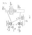
- FIG. 3is a schematic illustration showing a system that includes a first data center in communication with a second data center via a network.
- FIG. 5is a flow diagram showing a method of allocating resources in accordance with an embodiment of the system described herein.
- FIG. 6is a schematic illustration showing a system including a storage array with thin pools and a root sandbox according to an embodiment of the system described herein.
- FIG. 7is a schematic illustration showing a virtualization environment (VE) including an storage pool manager (SPM) according to an embodiment of the system described herein.
- VEvirtualization environment
- SPMstorage pool manager
- FIG. 8is a schematic illustration of a VE hierarchy for compute and storage resources using a sandbox according to an embodiment of the system described herein.
- FIG. 9is a schematic illustration showing a VE hierarchy, like the VE hierarchy in FIG. 8 , with an example assigning of sandbox storage resources using a resource scheme according to an embodiment of the system described herein.
- FIG. 10is a flow chart show LUN creation operations performed using the SPM according to an embodiment of the system described herein.
- FIG. 11is a flow chart show LUN deletion operations performed using the SPM according to an embodiment of the system described herein.
- FIG. 12is a schematic illustration showing SPM mapping and masking according to an embodiment of the system described herein.
- FIG. 1is a schematic illustration of a server system 10 that includes a plurality of routers 32 - 34 , each of which may be used to interconnect a plurality of subnets 42 - 44 that may be used in connection with an embodiment of the system described herein.
- Each of the subnets 42 - 44may include a subset of a plurality of servers 51 - 59 .
- the servers 51 - 59may communicate using any of a number of appropriate protocols, such as TCP/IP.
- Each of the servers 51 - 59may be provided with a private IP address (e.g., 192.168.X.X) or a public IP address.
- the routers 32 - 34manage data communications to and from the servers 51 - 59 .
- each of the subnets 42 - 44is shown as having three servers, the number of servers coupled to a subnet may be any number, possibly limited only by the physical address space of the subnet. In addition, there may be any number of subnets and, in some instances, the topology of the server system 10 may be different than that shown.
- a server systemshould be understood as including any system having a plurality of separately addressable servers that may be externally accessible (e.g., through the Internet and/or other network).
- one or more of the servers 51 - 59may be subdivided into a plurality of virtual machines.
- a virtual machineis a software implementation of a machine that executes programs like a physical machine. Virtualization software allows multiple virtual machines with separate operating systems, to run in isolation on the same physical machine. Each virtual machine may have its own set of virtual hardware (e.g., RAM, CPU, NIC, etc.) upon which an operating system and applications are loaded. The operating system sees a consistent, normalized set of hardware regardless of the actual physical hardware components.
- the term “virtualization software”is used herein to generally refer to any and all software that supports the operation of one or more virtual machines.
- a benefit of providing virtual machinesis the ability to host multiple, unrelated, tenants (users) in a single physical server. For example, three unrelated clients, each hosting their own Web site, may all reside on a single one of the servers 51 - 59 that is running virtualization software to present what looks like a single stand-alone server to each of the clients as well as other visitors to the Web sites.
- the virtualization softwaremay maintain separation of each of the clients, which each separately access their own virtual server(s).
- Operations of virtual machinemay include using virtual machines images.
- a virtual machine imageis a file containing a program that may be loaded and executed by a virtual machine and may include additional information used in connection with executing the program.
- a virtual machine imagemay be obtained for an operating virtual machine and transferred to another location where another virtual machine may use the virtual machine image to continue execution of the program from the state defined by the virtual machine image.
- the virtual machine imagemay be a snapshot of an execution state of a program by a virtual machine that may be moved between different locations and processing thereafter continued without interruption.
- Configuring and deploying virtual machinesis known in the field of computer science.
- U.S. Pat. No. 7,577,722 to Khandekar, et al.entitled “Provisioning of Computer Systems Using Virtual Machines,” which is incorporated herein by reference, discloses techniques for configuring and deploying a virtual machine according to user specifications.
- Virtual machinesmay be provisioned with respect to any appropriate computing resource, including, for example, CPU processing resources and/or memory.
- a virtual centerthat may be referred to as a vCenter, may provide a central point of control for managing, monitoring, provisioning and migrating virtual machines, as further discussed elsewhere herein.
- the virtual centerprovides for managing virtual machines to be deployed and may perform virtual machine lifecycle management tasks, administer users and roles, and view usage metrics, among other functionality.
- Virtual centersmay operate to control virtual machines in data centers and in connection with cloud computing including using both internal and external cloud infrastructures and hybrids thereof.
- the client software 84interacts with the servers 51 - 59 through different ones of the interfaces 91 - 93 at the same time.
- Virtualization softwaremay be provided as part of the interface layer 90 and/or the server operations software 82 .
- the client 80and software thereof, may operate in connection with accessing web services for on-demand processing, such as computing and storage functions, in cloud environments and including the provisioning of resources, as further discussed elsewhere herein.
- the client 80may be a vSphere client from VMware, Inc. in Palo Alto, Calif., as further discussed elsewhere herein.
- a service level agreementmay include various customer requirements and service provider objectives in connection with providing services, such as cloud computing services.
- the SLAmay indicate how many virtual machines a customer estimates would be required over certain time periods, for example, on a hourly, daily, weekly basis, etc.
- the SLAmay indicate processing performance requirements (for example processing requirements measured in GHz-hours), network performance requirements and/or storage requirements, among any other suitable requirements set forth in the SLA.
- the SLAmay be stored in a computer-readable format in which requirements of the SLA may be harvested for use in connection with the system described herein.
- the SLAsmay be stored on and/or accessible by the servers 51 - 59 and/or the client 80 .
- the data centers 102 , 104may contain any number of processors and storage devices that are configured to provide the functionality described herein.
- the storage devicesmay be Symmetrix storage arrays provided by EMC Corporation of Hopkinton, Mass. Other appropriate types of storage devices and different types of processing devices may also be used in connection with the system described herein.
- the data centers 102 , 104may be configured similarly to each other or may be configured differently.
- the network 106may be any network or similar mechanism allowing data communication between the data centers 102 , 104 .
- the network 106may be the Internet and/or any other appropriate network and each of the data centers 102 , 104 may be coupled thereto using any appropriate mechanism.
- the network 106may represent a direct connection (e.g., a physical connection) between the data centers 102 , 104 .
- the active VMs 112 - 114may be provided in an active repository 132 , which includes one or more logical storage volumes for maintaining the active VMs 112 - 114 .
- the passive VMs 122 - 124may be provided in a passive repository 134 , which includes one or more logical volumes.
- Each of the volumes of the active and passive repositoriesmay include multiple VMs.
- VMsmay be migrated from a source one of the data centers 102 , 104 to a target one of the data centers 102 , 104 .
- one or more of the data centers 102 , 104may use thin provisioning with a mechanism for reclaiming released storage space and/or for reserving storage space.
- Such mechanismsare disclosed in U.S. patent application Ser. No. 12/924,388 to Balcha et al., filed Sep. 27, 2010 entitled “Storage Space Reclaiming for Virtual Provisioning,” and U.S. patent application Ser. No. 12/924,474 to Fradkin et al., filed Sep. 28, 2010, entitled “Virtual Provisioning Space Reservation,” which are both incorporated by reference herein and are assigned to the assignee of the present application.
- FIG. 5is a flow diagram 200 showing a method of allocating resources in accordance with an embodiment of the system described herein.
- a processor or other software-tool componentmay access stored user processing requirements, such as compute processing requirements including CPU cycles and/or memory resources, for a computing environment.
- the processing requirementsmay be obtained from users' SLAs and/or input by the user in connection with the system described herein.
- processingproceeds to a step 204 where the users' virtual machine needs are analyzed according to the obtained processing requirements and one or more VMs are determined based thereon.
- processingproceeds to a step 206 where the VMs of one of more of the users are provisioned and may assigned to one or more of the clusters of VMs in connection with an allocation of resources that supports the users' virtual machine needs based on the obtained processing requirements.
- processingproceeds to a test step 208 where it is determined whether the allocation of resources for one or more of the clusters needs to a modified to reflect changed processing requirements.
- the changes to the processing requirementsmay include a change to one or more of the SLAs of current users' reflecting changes in the virtual machines required for the current users, may include a change to assign virtual machines from a new user and/or may reflect the tracking of usage metrics of the users, as further discussed elsewhere herein.
- the systemmay automatically periodically review the allocation of resources to determine if changes are necessary for current user SLA requirements. If at the test step 208 , it is determined that resource allocation is to be modified, processing may proceed back to the step 202 . If at the test step 208 , it is determined that the resource allocation is not to be modified, then processing is complete.
- a storage pool managermay simplify the provisioning and assigning of resources, including storage, for virtualized environments (VEs).
- Virtualized server environmentsfor example, as represented by VMware, may be highly dynamic. For example, users may provision a new server on a virtual machine (VM) in minutes in a VE.
- VMvirtual machine
- storage provisioningmay not be dynamic, but rather be intended to be done by a centralized resource, the storage administrator, who has the specialized skills necessary to provision storage from the storage array.
- provisioning new storage from a storage array for a VMcan take days, for example.
- the SPMaccording to the system described herein may make storage provisioning as dynamic as the virtualized server provisioning. The SPM may accomplish this by pushing the provisioning of storage to the VE end-user and by simplifying it so that a non-storage savvy VE user can provision the storage.
- the SPMmay involve use of a storage type and a virtual container, e.g., called a root sandbox, to provide capability of storage provisioning to non-storage savvy VE users according to the system described herein.
- a storage typemay be a label for a particular kind of storage. This makes it simple for a user to provision the type of storage that is desired.
- the VE userinstead of a VE user provisioning 50 GB of RAIDS 3+1 storage on 10,000 RPM FC drives, the VE user may simply provision 50 GB of “Silver” or 50 GB of “Tier2” storage.
- the storage administratormay define the types of storage available.
- the storage administratormay do this by using defined storage tiers, such as in a fully automated storage tiering (FAST) system, and/or by creating a custom type.
- the storage administratormay create custom types by selecting the properties of the physical storage: disk type (e.g., SATA, FC, SSD), disk speed (e.g., 7200, 10,000, 15,000), and RAID configuration (e.g., RAID6 14+2, RAID6 6+2, RAIDS 7+1, RAIDS 3+1).
- the storage administratormay also define storage types according to a FAST policy or a FAST SLA.
- SPMallows VE users to provision storage
- the storage administratormay still own and control the storage array, and thus may need to be able to set boundaries or parameters around what storage the users can provision. These boundaries and parameters may be defined by the sandbox.
- a sandboxis an example of a logical storage construct (virtual container) that may be configured using one or more physical storage arrays (e.g., Symmetrix) in which the storage administrator has given VE users permission to create LUNs.
- the storage of the sandboxmay include one or more thin pools of storage.
- a thin pool of storagecorresponds to the storage concept of thin or virtual provisioning that allows for the creation of logical volumes of storage space where allocation of physical storage space occurs only when space is actually needed (e.g., when data is written the first time to the storage space).
- the storage of the sandboxmay include storage pools other than thin pools, such as thick pools, pools for FAST policies, etc.
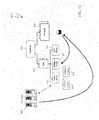
- FIG. 6is a schematic illustration showing a system 300 including a storage array 320 with storage pools, such as thin pools 321 - 323 and a root sandbox 310 according to an embodiment of the system described herein.
- the storage array 320may be a Symmetrix storage array and/or other appropriate storage array.
- Each thin poolmay be storage of a particular type, which may be defined by the type of data devices that make up the thin pool. For example, if “Silver” type storage has been defined by the storage administrator to be RAIDS 3+1 on 10,000 RPM FC drives and the data devices in thin pool tp1 321 contain data devices that match this, then tp1 321 is said to contain “Silver” storage.
- the sandbox 310contains 200 GB of “Silver” storage.
- Multiple thin poolsmay be put into the same sandbox, as long as they are from the same array and are different storage types. Therefore, it would be possible, for example, for the sandbox 310 to have 50 GB of “Gold” storage, 200 GB of “Silver” storage and 400 GB of “Bronze” storage, as illustrated.
- the storage administratormay assign the sandbox 310 to a VE virtual center instance, such as a vCenter.
- a VE virtual center instancesuch as a vCenter.
- GUIgraphical user interface
- SMCstorage management console
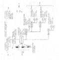
- FIG. 7is a schematic illustration showing a virtualization environment 400 including an SPM 410 according to an embodiment of the system described herein.
- the components in the illustrated environmentsare: a storage array 420 , such as a Symmetrix array; one or more ESX servers 430 and/or other similar type of servers; a storage area network (SAN) 435 ; an SMC server 440 with SPM functionality; a cloud-computing client 450 , such as a computer running vSphere with a storage viewer plug-in (e.g., storage viewer products produced by EMC Corp.); and a computer with a SMC GUI 460 with SPM functionality enabled; and a virtual center server 470 .
- a storage array 420such as a Symmetrix array
- SANstorage area network
- SMC server 440 with SPM functionalitysuch as a computer running vSphere with a storage viewer plug-in (e.g., storage viewer products produced
- the SPM 410 functionsmay be performed using a combination of enhanced functions of the SMC server 440 and the SMC GUI 460 , as further interfaced by the client-computing client 450 with storage view plug-in, and which enhances and abstracts the storage array 420 functionality in order to integrate storage provisioning into the VE 400 .
- the SMC server 440may be upgraded with the centralized SPM functions.
- the SMC GUI 460may be enhanced with the SPM UI functions needed for a storage administrator 461 , and functions for a VE administrator 451 and a VE user 452 may be added to the cloud-computing client 450 storage viewer.
- CPU cycles and memorymay be managed as resources that can be allocated to create virtual machines. For instance, the sum of all the CPU cycles on all the processors on all the servers in a cluster may be used to create a “pool” of CPU cycles for the clusters. As users create VM's, the users allocate CPU cycles from this pool for the VM. Furthermore, the cluster's pool of CPU cycles can be broken down into sub-pools, called resource pools, to provide finer granularity of control where, for example, a marketing VE user could only create a VM from the CPU resources in the marketing resource pool. The same may be done for all the memory on all the servers in the cluster.
- the system described hereinallows for storage to be treated as a third resource which can be controlled and allocated in the same way.
- the SPM 410may provide a mechanism for the storage administrator 461 to setup a bounded set of physical storage and allow him to give this set of physical storage to VE users (e.g., the VE user 452 ) for them to provision.
- the SPM 410may only allow VE users to provision storage that they have been given permission to by the storage administrator 461 .
- the SPM 410simplifies storage provisioning and provides a tight integration with VM provisioning by allowing VE users to provision storage from within the cloud-computing client 450 (e.g., vSphere) thereby allowing VE users to easily create a raw device mapping (RDM) LUN for a VM or a virtual machine file system (VMFS) data store for a cluster.
- RDMraw device mapping
- VMFSvirtual machine file system
- the SPM 410may integrate storage as a third VM resource.
- storagemay become a resource that can be managed and allocated as part of VE clusters and resource pools, just like CPU cycles and memory.
- the SPM 410may further support Symmetrix V-Max arrays and offers advantages in scale and registration.
- each SMC server 440may manage up to 5,000 SPM LUNs.
- the SMC server 440may include a server component in a manager element of the storage array 420 .
- the SMC server 440allows the storage administrator to control one or more storage arrays via a browser based GUI 460 .
- the SMC server 440stores the SPM data and performs SPM functions as requested by the storage administrator via the SMC GUI 460 , and requested by the VE users and administrators via the client storage viewer 450 .
- a single SMC servercan support multiple clients.
- the SMC GUI 460may be a client front end to the SMC server 440 .
- the storage viewermay be a plug-in to the VE client 450 .
- the storage viewermay be a storage viewer product produced by EMC Corp. and the VE client 450 may be VMware's vSphere client.
- the storage viewermay provide the VE user 452 and the VE administrator 451 with the user interface to interact with the SPM functionality.
- the storage viewermay contain some logic to perform some of the VE tasks related to storage provisioning.
- a VE client 450may talk to more than one SMC/SPM server 440 .
- the functions of the SPM 410may be performed according to three types of users, or roles: the storage administrator 461 ; the VE administrator 451 ; and the VE user 452 . It may be noted that the VE administrator 451 may also perform the functions of the VE user 452 . Further, in an embodiment, the functions of the SPM 410 may be broken down into four operational phases which are listed below and further discussed elsewhere herein:
- the SPM 410may automate several tasks, for instance mapping and masking, that were previously performed manually. These automated functions are further discussed elsewhere herein.
- the storage administrator 461may interact with the SPM 410 via the SMC GUI 460 .
- the storage administrator 461may be responsible for:
- policiesmay include maximum and minimum LUN size and maximum number of LUNs created from the sandbox;
- the storage administrator 461may be logged into the SMC 460 as a user with the admin or storage admin role.
- the VE administrator 451may interact with the SPM 410 via the a GUI on the cloud-computing client 450 with the storage viewer plug-in.
- the VE administrator 451may be responsible for assigning storage to VE objects, data centers, clusters, and resource pools, from the sandboxes which have been assigned to the vCenter server 420 .
- the VE administrator 451may be restricted to assigning storage only to those VE objects to which he has VE authorization to administer.
- the VE user 452may interact with the SPM 410 via the cloud-computing client 450 GUI with the storage viewer plug-in.
- the VE user 452may:
- Preparing the storage environmentmay be performed by the storage administrator 461 and may involve some setup of the storage array 420 and the SPM 410 so that later operations, such as sandbox creation and storage provisioning, can be successfully completed.
- the followingis a set of array operations that the storage administrator 461 may perform so that the SPM 410 may be used successfully.
- the operationsmay be performed done using the standard SMC functionality.
- Thin poolsmay be created that may later be put into sandboxes (see FIG. 6 ).
- Masking views for the server clustersmay be created in the VE environment 400 .
- the storage administrator 461may begin creating sandboxes and assigning them to virtual center instances.
- Setting up a sandboxmay involve creating a sandbox with a name, description, and the GUID of the vCenter that the sandbox is assigned to.
- Previously created views to the sandboxmay be assigned. In an embodiment, there may be one, and only one, view for each VE cluster that the storage in the sandbox will service.
- Previously created thin poolsmay be added to the sandbox. Note that, in an embodiment, all the thin pools added to the sandbox may come from the same array. When adding a thin pool to the sandbox the storage administrator has two decisions to make.
- a sandboxmay only contain one thin pool of each storage type.
- the provisioning policiesmay be then be determined.
- the policies that may be set for a sandboxinclude:
- Pre-creation policiesmay also be set as further discussed elsewhere herein.
- the next operational phaseis for the VE administrator to allocate storage to VE resources or objects.
- the highest level objectmay be the virtual center that may be a centralized management server.
- a virtual center servercan control one or more data centers.
- a data centermay be composed of one or more clusters.
- a clustermay be composed of one or more ESX servers.
- CPU cycles and memorymay be compute resources.
- the sum of all the CPU cycles and memory of the servers in the clustermay determine the cluster's compute resources.
- a cluster's compute resourcescan be divided into resource pools. Resource pools can be further divided into more resource pools.
- VM'sare created from the compute resources of a cluster or one of its child resource pools. The system described herein provides that storage may be added as another resource to the virtualized environment along with the CPU cycle and memory resources.
- FIG. 9is a schematic illustration showing a VE hierarchy 500 ′, like the VE hierarchy 500 shown in FIG. 8 , with an example assignment scheme of resources including sandbox storage resources (e.g., CPU, memory and storage: Gold, Silver, Bronze) according to an embodiment of the system described herein.
- the storage administratormay assign the sandbox 510 with 50 GB of Gold, 200 GB of Silver and 500 GB of Bronze storage to the virtual center 520 .
- the storage in the sandbox 510is available to the virtual center 520 . Note that it is possible to assign more than one sandbox to the same virtual center.
- a VE administratormay now assign the storage available to the virtual center 520 to one or more data centers, like the data center 530 , that are children of the virtual center 520 .
- the VE administratormay assign all of the storage to that data center 530 .
- there is only one cluster 540 in the data center 530so the VE administrator also assigns all the storage in the data center 530 to the cluster 540 .
- the cluster 540has compute resources, CPU and memory, and the storage assigned to the cluster thus becomes another resource to the cluster 540 .
- the VE administrator who has control over the cluster 530can divide the storage resources among the cluster's child resource pools 550 , just like division of the CPU and memory resources.
- the SPM 410may automate several functions that today must be performed by the storage administrator, VE administrator or VE user. For example, when the VE user creates a LUN for an RDM or VMFS, a thin device is created in a thin pool. This thin device is mapped to a set of front end array ports and then masked to the ESX cluster the LUN is needed on. SPM does this by automatically putting the device into the storage group which belongs to the view associated with the sandbox which has an initiator group that matches the server ports for the VE cluster that the LUN is being created for. If there is no view associated with the sandbox that has an initiator group with all the cluster ports then the create LUN fails. This prevents LUNs from being created that are only masked to some of the servers in the cluster or not masked to all the paths to each server.
- the VE administratormay use the cloud-computing client to refresh the server membership of a cluster. This updates SPM knowledge of what server port WWN's comprise the clusters. Each time a LUN is created the WWN's for the cluster are checked against the initiator groups to make sure that the LUN is masked correctly to cluster. If the server membership changes the storage administrator must update the initiator group for the server cluster.
- the SPM 410may automatically track the used and available storage for each VE object. For example, if a resource pool has 60 GB of Silver storage, of which 10 GB of used, and a VE user creates a 15 GB RDM from Silver storage for a VM in that resource pool, then after the RDM creation there will be 25 GB of used and 45 GB of available Silver storage for the resource pool.
- the SPMmay also enforce the provisioning policies that the storage administrator sets on the sandbox. Policies may include, for example: maximum number of LUNs provisioned; maximum LUN size; minimum LUN size; and provisioning only pre-created LUN sizes.
- a VE usercreates a thin device, for an RDM or VMFS, if the VE user chooses one of the pre-created sizes the provisioning time is reduced to the time it takes to map and mask the device. If the VE user chooses a size that is not pre-created then he must wait the additional time it takes to create the thin device.
- the pre-creation policymay cause devices of particular sizes to be pre-created and reserved for SPM use. These may be called SPM un-used LUNs.
- SPM un-used LUNsWhen a VE user creates a LUN of this size, the SPM will look for an SPM un-used LUN of this size. If one exists, that LUN will use it instead of creating a new device from scratch. This may significantly speed up the provisioning process as the pre-created device simply has to be added to the correct storage group to mask it to the VE servers.
- a pre-creation policymay be defined by one or more of the following:
- the combination of the sandbox and the storage typemay determine which thin pool the pre-created devices are created in.
- a reservationmay be created for the SPM 410 .
- Thin devices created by SPM 410including pre-created ones, may be reserved under this reservation. This allows storage administrators managing the storage array to know which devices are under the control of SPM 410 .
- the SPM 410may automatically create an SPM reservation. All devices that are under the SPM's control may be reserved with this reservation. This makes the storage administrators working on the storage array aware that these devices are being used by the SPM 410 . Devices may be added to the SPM reservation when they are created by the SPM 410 and/or when they are adopted into the SPM 410 .
- Devicesmay be released from the SPM reservation when they are deleted by SPM 410 and/or when the thin pool they are in is removed from a sandbox, as further discussed elsewhere herein. If a thin pool is associated with multiple sandboxes, then only the devices for LUNs in the sandbox the thin pool is being removed from are released from the reservation.
- SPM meta-datamay be backed up to an external directory (the meta-data may exist as a set of files).
- the SPM configurationmay be restored from a previous backup.
- best practicemay be for the SPM meta data to be backed up along with the masking database.
- the SPM configurationmay get out of sync with the VE configuration. This is because the VM user may take actions through the cloud-computing client that SPM will not be aware of. An example of this is moving a VM from one resource pool to another. Refreshing the SPM configuration may align it with the current VE configuration.
- the SPM 410may be deployed in an existing VE configuration (e.g., an existing VMWare configuration) so that it can be used to handle any new storage provisioning. This may require that the SPM 410 be able to adopt existing LUNs and bring them under SPM control. Note that this feature may only be available for thin LUNs/devices.
- an existing VE configuratione.g., an existing VMWare configuration
- the SPM 410accommodates a number of use cases and functional details related to functions of the storage administrator, VE administrator and the VE user according to various embodiments of the system described herein. Examples of these use cases and functional details are discussed elsewhere herein in connection with TABLES 1-26.
- LUN creationmay be initiated by a VE user requesting to create a LUN for a VE cluster, for example as an RDM for a VM or a VMFS data store for the VE cluster.
- the requestmay come to the SMC server as a request to create a LUN with the following parameters:
- FIG. 10is a flow chart 600 show LUN creation operations performed using the SPM 410 according to an embodiment of the system described herein.
- processingis performed to determine the thin pool from which to create the LUN device.
- the sandbox and storage typemay be used to determine the thin pool the device will be created in.
- processingproceeds to a step 604 where validations are performed. Several validations may be done before the device is created on the storage array. The validations may include that the cluster may be used to verify that all the server ports in the VE cluster are represented in an initiator group in a view that is associated with the sandbox.
- the sandbox provisioning policiesmay be examined to make sure that creating this device would not violate any of the policies, e.g. maximum or minimum size. Additionally, it may be determined whether the vCenter may be authorized to perform operations on the thin pool and the storage group to be used for the masking.
- processingis complete, as is shown by a dashed lined. However, in other embodiments, processing may proceed to a test step 624 in connection an analysis of devices of pre-created policies according to an embodiment of the system described herein. That is, at the test step 624 , it may be again determined whether the added device matched the size of a pre-created policy. If not, then processing is complete since the creation of the LUN did not involve the pre-created policies.
- LUN deletionmay be initiated by the VE user when the VE user wants to delete a VMFS data store for a cluster or an RDM for a VM, for example. Before operations to delete a device is on the storage array, it may first be verified that the vCenter is authorized to perform operations on the thin pool and the storage group in which the device is located.
- FIG. 11is a flow chart 700 show LUN deletion operations performed using the SPM 410 according to an embodiment of the system described herein.
- the operationsmay have been appropriate validated, for example, by determining that the vCenter is authorized to perform operations on the thin pool and the storage group to be used for the masking.
- Processing of the flow chart 700may begin at a test step 702 where, in connection with an examination of the sandbox pre-creation policies, it is determined whether a size of the LUN device matches a pre-creation policy.
- processingproceeds to a step 704 , where the device is removed from storage group, making it an SPM un-used device.
- processingproceeds to steps in connection with reclaiming space from the device, including a step 706 where the device is released from the SPM reservation.
- processingproceeds to a step 708 where the device is unbound from the thin pool.
- processingproceeds to a step 710 where the device is then rebound to the thin pool.
- processingproceeds to a step 712 where the device is added to the SPM reservation.
- processingproceeds to a test step 714 where it is determined whether the device removal and space reclaiming steps were successful. If so, then processing is complete. If the steps were not successful as result of errors occurring at any of the above-noted steps, then processing proceeds to a step 716 where error processing is performed. In an embodiment, the error processing may simply be a report and/or other notification if recovery from an error that occurs during the deletion processing of a LUN is not possible. After the step 716 , processing is complete.
- the storage group 832may be an existing one and/or may be a new one. If it is a new one, the storage group 832 may be created with a single device that will not be used unless it is adopted.
- a devicemay be created in the thin pool 820 as determined by the sandbox 810 and the storage type.
- the devicemay be put into the storage group 832 that is in the view 830 associated with the sandbox 810 that has the initiator group 833 for the VE cluster 840 .
- LUNs/devices that the SPM controlsmay be individually tracked by the SPM by storing meta information about each device in its persistence store.
- all the devices that SPM controlsmay be reserved by the SPM reservation and each LUN/device may have two states: (1) used—device is being used by a VE cluster and (2) un-used—device has been pre-created and is waiting to be masked to a VE cluster.
- the used-devicemay be tracked by SPM meta data, reserved by the SPM reservation and/or masked to a VE cluster by virtue of being in a storage group in a view associated with a sandbox.
- the un-used devicemay be tracked by SPM meta data and/or reserved by the SPM reservation.
- adopt LUNsmay be used to bring LUNs/devices, that are currently not under SPM control, under SPM control.
- Adopting LUNsmay be done to repair an SPM configuration that has been corrupted or lost, and/or to put an existing VE configuration under SPM control.
- Adopting LUNs occursmay after a sandbox has been created, a view(s) for the VE cluster is associated with the sandbox, and a thin pool(s) is added to the sandbox. At this point, devices that are in the thin pool(s) which have been added to the sandbox may be eligible to be adopted.
- an adoptable LUNis defined by a LUN that is: not reserved, or already reserved by SPM, and in a storage group that is part of one of the views associated with the sandbox. It could also be in a storage group that is in a view which has one of the initiator groups in one of the views associated with the sandbox.
- the LUNmay be masked to one of the VE server clusters the sandbox is servicing.
- the storage administratormay specify the amount of capacity from the thin pool to be assigned to the sandbox.
- the amount that is assignedis a subscribed or virtual capacity. Subscribed capacity is a presented capacity and not a physical capacity. Thus, the storage administrator may choose to over subscribe the thin pool by assigning more storage than is physically available. In order to guide the storage administrator in determining how much subscribed capacity to assign to the sandbox, the storage administrator may be presented with several values:
- An authorization on a thin poolalso allows the user to: create/delete a device; bind a device to an authorized thin pool; unbind a device from an authorized thin pool; reserve a thin device belonging to an authorized thin pool; and release a thin device belonging to an authorized thin pool from a reservation. Embodiments for reserving and releasing thin devices are further discussed elsewhere herein.
- An authorization on a storage groupallows a user to put a device into a storage group or remove a device from a storage group.
- the above authorizationsmay have two functions. One is to ensure that the cloud-computing clients can only manipulate storage array storage objects on which they are authorized. The other is to provide some protection from other storage administrators to the storage array objects that the SPM 410 is using.
- storage provisioning commands from the cloud-computing clientmay come with a user id and group id.
- the user idmay the name the user used to login to the vCenter server.
- the group idis the GUID of the vCenter server. In practice, it is the group id, the vCenter server GUID, that may be used to validate the provisioning command against the required permissions on the storage array (e.g., Symmetrix).
- VE usersmay be restricted by the storage viewer plug-in to performing provisioning operations on storage for VE objects to which they have access. For instance, a VE user may only create or delete an RDM for a VM on which he has VE configuration authorization.
- logsmay be generated for SPM operations in the SMC log.
- log entriesinclude: all SPM operations that occur between the cloud-computing client and SMC client and the SMC server; all array configuration and control operations that occur during an SPM operation; and internal error conditions
- SA Triggers SAwants to setup a storage environment that can be managed by SPM. Preconditions 1. The SA has access to the SMC server via a browser Basic Course of 1. SA accesses the storage type creation dialog Events 2. SA selects a tier he wants the storage type to be created from. 3. SA presses the OK button. Alternative Paths 1. SA accesses the storage type creation dialog 2. SA enters a name for the storage type 3. SA enters a description for the storage type 4. SA selects the properties from each of several categories that define the storage type.
- RAID Configurationi. RAID1 ii. RAIDS 3 + 1 iii. RAIDS 7 + 1 iv. RAID6 6 + 2 v. RAID6 14 + 2 b. Disk Type i. EFD ii. FC 7200 RPM iii. FC 10,000 RPM iv. FC 15,000 RPM v. SATA 5. SA presses the Add button. Exception Paths 1. Storage type name already exists Postconditions 1. The new storage type is persisted. Notes 1. If FAST tiers are used to create a storage type than the tier name is used to create the storage type name. 2.
- a FAST tieris used to create a storage type, once the storage type is created it is independent of the tier. Changes to the tier do not affect the storage type and the storage type itself can be updated independent of the tier. 3. Two different storage types can have exactly the same property set. 4. Storage types can be created which do not have any settings for a particular property, e.g. Disk type. In fact, a storage type can be created without any properties at all. In this case it can used to describe the storage in any thin pool.
- Update Storage TypeUse Case Name Update storage type Description Updates a storage type. This includes changing its name or description. Actors Storage admin, SA Triggers The SA decides he wants to modify this storage type. Preconditions 1. The SA has access to the SMC server via a browser Basic Course of 1. A list of storage types is displayed. Events 2. The SA selects the storage type to update and the characteristics of the storage type are displayed: a. Name b. Description 2. The SA can change the name, or the description. 3. The SA clicks OK Alternative Paths 1. None Exception Paths 1. Updating the storage type name to one that already exists. Postconditions 1. The storage type is updated
- Adding a viewwill fail if the vCenter server does not have authorizations on the storage group in the view 3.
- the viewdoes not exist on the array associated with the sandbox Postconditions 1.
- LUNscan now be masked to the VMware cluster whose HBA ports match the WWN's in the added view's initiator group Notes 1.
- a viewcan be attached to multiple sandboxes
- the sandboxcan only contain thin pools from the same array. 2.
- the sandboxcan only contain one thin pool of each storage type. 3.
- a thin poolcan provide storage to more than one sandbox. 4.
- the amount of capacity added to a sandbox from a thin poolis subscribed capacity, not physical capacity. The total amount of subscribed capacity in a thin pool is determined by multiplying its enabled physical capacity by the maximum subscription percent (a thin pool property set by the SA) minus capacity already assigned to other thin pools and to other thin devices not in any sandboxes.
- Remove thin pool from sandbox DescriptionRemoves a thin pool from a sandbox. This dissolves the association between the sandbox and the thin pool. It leaves any LUNs in the thin pool in place, but removes the SPM reservation on them.
- Actors Storage adminSA Triggers The SA wants to remove a thin pool from a sandbox Preconditions 1. The SA has access to the SMC server via a browser Basic Course of 1. SA selects a sandbox Events 2. A list of the thin pools in the sandbox is shown 3. SA selects a thin pool to remove from the sandbox Alternative Paths 1. None Exception Paths 1. None Postconditions 1.
- Adopt LUNs Use Case NameAdopt LUNs Description
- a thin pool that is being added to a sandboxmay already have devices in it that users want to be controlled by the SPM. This could be because the storage pool manager meta-data has been corrupted or deleted, or the user wants to bring an existing VMware configuration under SPM control.
- Actors Storage adminSA Triggers The SA wants to repair a deleted or damaged SPM configuration or put an existing VMware configuration under SPM control Preconditions 1.
- the SAhas access to the SMC server via a browser Basic Course of 1.
- the adopt LUN dialogis displayed for a sandbox Events 2.
- a list of the current devices in the thin pool matching the following criteriaare displayed: a. Device is not reserved, or already reserved by SPM b.
- a storage groupin a view, that has an initiator group that is in one of the views assigned to the sandbox 3.
- the SAselects which of the devices to adopt. Alternative 1. None Paths Exception Paths 1. None Postconditions 1.
- the selected devicesare adopted to be managed by SPM. They are placed in the sandbox, and their capacity is added to the sandbox's total capacity. 2. The devices are added to the SPM reservation Notes 1.
- a VMware usermust now run refresh which determines the VM's each device is attached to and then straightens out the capacity accounting.
- Adopt an existing VMware configuration DescriptionSPM is being deployed in an environment where there is an existing VMware configuration that already uses storage from a Symmetrix.
- the existing thin pools and thin LUNsneed to be brought under SPM control Actors Storage admin, SA Triggers
- the SAwants to bring an existing VMware environment under SPM control Preconditions 1.
- the SAhas access to the SMC server via a browser 2.
- the SAhas both the storage administrator and security administrator role on the Symmetrix(s) Basic Course of 1.
- SAeither creates new views to use to mask new Events LUNs to the VMware cluster, or decides to use the existing ones. If he creates new ones, they would use the existing initiator groups that contain the WWN's for the VMware cluster. 2.
- the SAenters authorizations for the vSphere server on the thin pools that contain the LUNs currently in use by the VMware cluster and for the storage groups in the views of the previous step. 3.
- SAeither decides to use some existing storage types, or create new ones. In either case there must be one per thin pool that is going to be put into the sandbox. 4.
- the SAcreates a sandbox as normal 5.
- the SAselects thin pools to add to the sandbox. These thin pools already contain the devices which are mapped to the VMware configuration. 6.
- the SAselects which LUNs to adopt, see the use case 0 7.
- the VMUserdoes a refresh configuration.
- the existing configurationis now under control of SPM. Notes 1. This is only supported for thin pools and thin devices
- a VMware administratorcan allocate the storage in that sandbox to VMware objects, i.e. data centers, ESX servers, clusters or resource pools.
- Actors VMware administrator, VMAdmin TriggersA VMAdmin needs to make some storage available for provisioning to a VMware data center, ESX server, cluster or resource pool Preconditions 1.
- Viewer plug-inis installed into the vSphere client 2.
- vSphere clienthas access to the SPM/SMC server 3.
- a sandboxhas been assigned to the vSphere server that the VMAdmin has permission on Basic Course of 1.
- the VMAdminselects the data center, ESX server, Events cluster or resource pool he wishes to allocate storage for 2.
- the VMAdminis presented with the available storage, by storage type, from the parent of this VMware object. If the parent has not been explicitly allocated storage then its parent is examined, etc. all the way up to the virtual center if needed. 3.
- the VMAdminenters the amount of storage he wants for each type of storage available Alternative 1. None Paths Exception Paths 1. If a clustered ESX server is selected no allocations can be made. Allocations can only be made to an ESX if it is not a member of a cluster. 2.
- the amount of requested allocationexceeds what is available from the parent object. 3.
- the amount of requested allocationis less than what is already in use at this object. Postconditions 1.
- the amounts of each typeare now allocated to this object; data center, ESX server, cluster or resource pool. Children of this object may now only allocate storage from the amounts and types available in this object, i.e. they cannot allocate
- the server members of a VMware ESX clustercan change or new HBAs may be added to an ESX server. When they change, the list of server FC ports for the cluster needs to be updated. Actors VMware administrator, VMAdmin Triggers The ESX cluster server membership has been changed Preconditions 1. Viewer plug-in is installed into the vSphere client 2. vSphere client has access to the SPM/SMC server Basic Course of 1. The VMAdmin selects the ESX server or cluster Events whose membership has changed 2. The VMAdmin selects refresh cluster membership Alternative 1. None Paths Exception Paths 1. None Postconditions 1. The list of server ports recorded for that cluster is updated. When a new LUN is created for this cluster the sandbox's views will be checked to make sure there is an initiator group that matches the members of the cluster. Notes 1. This does not change the membership of any initiator groups.
- Refresh configurationcauses the SPM configuration data to be aligned with the VMware configuration.
- the SPM configuration datacan become out of sync with the VMware configuration when changes are made to VMware configuration, for example creating or deleting a resource pool.
- Dialog boxasks the user to enter information about the RDM 3.
- the userselects the type of storage from the types available to the VM's VMware parent object 4.
- the usersets the size of the LUN by either selecting one of the pre-created sizes, or by entering an arbitrary size a. If the SA has set the policy that says that only pre-created LUN sizes may be used then the user will not be able to create arbitrary sized LUNs 5. Advanced settings will optionally be made available to configure RDM options such as device modes, etc. Alternative 1. None Paths Exception Paths 1. There is not enough available capacity for the storage type selected 2. Creating the LUN violates one of the provisioning policies put in place on the sandbox by the SA, e.g. maximum number of LUNs Postconditions 1.
- the size selectedwas a pre-created size and if there is an existing, free, thin device, then it is used, otherwise a new thin device is created 2.
- the thin deviceis added to the storage group for that thin pool/cluster combination. 3.
- the thin deviceis discovered by the servers in the cluster 4.
- An RDM for the VMis created from the thin device 5.
- Capacities for the VMware objectsare updated
- the deviceis an SPM device
- the userwill be asked if they wish to destroy the device and return storage to the pool or leave the device mapped to the cluster.
- the devicewas a non-SPM device, the RDM is removed and the device is still presented to the cluster. 2. The RDM will be removed from the VM, and depending on the answer to Event 3, will still be presented to the cluster or be deleted. 3.
- the LUNis to be deleted, the capacity of the LUN is checked against the pre-creation policies for the sandbox. a. If the capacity does not match any of the policies the device is deleted b. If the capacity matches a policy the device storage is reclaimed and the device is kept for a future LUN creation of that size 4.
- Capacities for the VMware objectsare updated
- VMFS Datastorefor a Cluster Use Case Name Create a VMFS Datastore for a cluster Description Creates a thin device and formats it as a VMFS Datastore Actors VMware user, VMUser Triggers The VMUser decides he needs a new VMFS Datastore for his cluster Preconditions 1.
- the SPM licensehas been installed on the SMC server 2.
- Viewer plug-inis installed into the vSphere client 3.
- vSphere clienthas access to the SPM/SMC server 4.
- Storagehas been allocated to the VMware object or one of its parents 5.
- vCenter serverhas authorizations on the thin pool and storage group that will be used 6.
- SANis zoned correctly Basic Course of 1.
- Delete VMFS Datastore from a Cluster Use Case NameDeletes the device(s) backing a VMFS Datastore Actors VMware user, VMUser Triggers The VMUser decides he needs a new VMFS Datastore for his cluster Preconditions 1.
- the SPM licensehas been installed on the SMC server 2.
- Viewer plug-inis installed into the vSphere client 3.
- vSphere clienthas access to the SPM/SMC server 4.
- Storagehas been allocated to the VMware object or one of its parents 5.
- a VMFS Datastoreis mapped to a cluster. 6.
- vCenter serverhas authorizations on the thin pool and storage group that will be used Basic Course of 1.
- VMFS Datastore Use Case NameExtend a VMFS Datastore Description Extend a VMFS Datastore. This use case is only valid for VMFS data stores composed of SPM LUNs. Actors VMware user, VMUser Triggers The VMUser decides he needs to extend and existing VMFS Datastore for his cluster. Preconditions 1. Viewer plug-in is installed into the vSphere client 2. vSphere client has access to the SPM/SMC server 3. Storage has been allocated to the VMware object or one of its parents 4. A VMFS Datastore is mapped to a cluster. 5. vCenter server has authorizations on the thin pool and storage group that will be used Basic Course of 1.
- the SPM 410pushes the provisioning of storage from a storage administrator out to virtualization users and administrators.
- storage provisioningis made as dynamic as server provisioning in a virtualization environment.
- Use of the SPM 410enables virtualization users to select storage for provisioning based on a request that includes selection of a type of storage and an amount without having to be knowledgeable about storage provisioning operations. The details of creating the storage and performing masking operations to the servers are done automatically.
- a virtual containeri.e. sandbox
- the storage administratoris able to control the storage that is accessible to virtualization users for provisioning and is able to set boundaries and policies around what storage the virtualization users can provision from.
- the virtualization administratoris allowed to sub-divide the storage made accessible from the storage administrator using a virtualization hierarchy like that provided for CPU and memory resources.
- the system described hereinmay be used in connection with end user provisioning of storage for various types of virtualization environments, such as enabled by VMware and/or Hyper-V, for example.
- the storage arrays used in connection with the system described hereinmay include arrays produced by EMC Corporation of Hopkinton, Mass., including Symmetrix and Clariion, as well as other appropriate types of storage arrays.
- the system described hereinmay be used in connection with storage tiering, as further discussed elsewhere herein, including FAST tiers, and storage types may be defined in terms of FAST tier policies and FAST SLA's rather than just in terms of physical storage characteristics.
- Suitable storage pools that may be used with the system described hereinmay include thin pools, thick pools, FAST pools and/or other appropriate kinds of storage pools.
- the computer readable mediummay include a computer hard drive, ROM, RAM, flash memory, portable computer storage media such as a CD-ROM, a DVD-ROM, a flash drive and/or other drive with, for example, a universal serial bus (USB) interface, and/or any other appropriate tangible or non-transitory storage medium or computer memory on which executable code may be stored and executed by a processor.
- the system described hereinmay be used in connection with any appropriate operating system. Further, any appropriate servers/routers may be used. Some or all of the routers may be replaced with other devices and/or some or all of the services provided by the routers may be provided by some or all of the servers.
Landscapes
- Engineering & Computer Science (AREA)
- Theoretical Computer Science (AREA)
- Physics & Mathematics (AREA)
- General Engineering & Computer Science (AREA)
- General Physics & Mathematics (AREA)
- Human Computer Interaction (AREA)
- Software Systems (AREA)
- Information Retrieval, Db Structures And Fs Structures Therefor (AREA)
Abstract
Description
- 1. Maximum Subscribed Capacity: This value is calculated by multiplying the maximum subscription percent (set by the storage administrator in SMC) by the physically enabled capacity of the thin pool. Thus this value represents the total subscribed capacity available.
- 2. Current Subscription Capacity: This value is the amount of the maximum subscribed capacity of the thin pool that has already been promised, but not necessarily used, to other things. It is calculated by adding up all the capacity that has been assigned to all sandboxes and the sum of capacities of all the thin devices in the pool that are not managed by SPM.
- 3. Available Subscription Capacity: This value is the difference between the maximum and current subscribed capacities. It represents the maximum capacity that a storage administrator can further assign from the thin pool.
In the client server configuration, the SMC server may reside on a separate server from the VE server. In the local server configuration, the SMC server and the VE server may reside on the same physical server. In the virtual appliance configuration, the SMC server and the VE server may be bundled together inside a VE virtual appliance that runs inside a VM running on a VE cluster.
| TABLE 1 |
| Create Storage Type |
| Use Case Name | Create a storage type |
| Description | Storage administrator creates a storage type from a previously defined |
| Symmetrix tier definition or by a set of physical storage properties. | |
| Actors | Storage admin, SA |
| Triggers | SA wants to setup a storage environment that can be managed by SPM. |
| 1. The SA has access to the SMC server via a browser | |
| Basic Course of | 1. SA accesses the storage type |
| Events | |
| 2. SA selects a tier he wants the storage type to be created from. | |
| 3. SA presses the OK button. | |
| 1. SA accesses the storage | |
| 2. SA enters a name for the storage type | |
| 3. SA enters a description for the storage type | |
| 4. SA selects the properties from each of several categories that define | |
| the storage type. Note that it is possible to make 0, 1, or N selections | |
| in a category. | |
| a. RAID Configuration | |
| i. RAID1 | |
| ii. RAIDS 3 + 1 | |
| iii. RAIDS 7 + 1 | |
| iv. RAID6 6 + 2 | |
| v. RAID6 14 + 2 | |
| b. Disk Type | |
| i. EFD | |
| ii. FC 7200 RPM | |
| iii. FC 10,000 RPM | |
| iv. FC 15,000 RPM | |
| v. SATA | |
| 5. SA presses the Add button. | |
| 1. Storage type name already exists | |
| 1. The new storage type is persisted. | |
| 1. If FAST tiers are used to create a storage type than the tier name is | |
| used to create the storage type name. | |
| 2. Even if a FAST tier is used to create a storage type, once the storage | |
| type is created it is independent of the tier. Changes to the tier do not | |
| affect the storage type and the storage type itself can be updated | |
| independent of the tier. | |
| 3. Two different storage types can have exactly the same property set. | |
| 4. Storage types can be created which do not have any settings for a | |
| particular property, e.g. Disk type. In fact, a storage type can be | |
| created without any properties at all. In this case it can used to | |
| describe the storage in any thin pool. | |
| TABLE 2 |
| Delete Storage Type |
| Use Case Name | Delete storage type |
| Description | Deletes a storage type |
| Actors | Storage admin, SA |
| Triggers | The SA decides he no longer wants this storage type. |
| 1. The SA has access to the SMC server via a browser | |
| Basic Course of | 1. A list of storage types is presented. |
| 2. The SA selects a storage type to delete | |
| 3. The SA clicks | |
| Alternative Paths | |
| 1. | |
| Exception Paths | |
| 1. The storage type is still being used to describe a thin | |
| pool to sandbox association. The storage type cannot be | |
| deleted until it is not being used by any thin pool. | |
| 1. The storage type is removed | |
| TABLE 3 |
| Update Storage Type |
| Use Case Name | Update storage type |
| Description | Updates a storage type. This includes changing its |
| name or description. | |
| Actors | Storage admin, SA |
| Triggers | The SA decides he wants to modify this storage type. |
| 1. The SA has access to the SMC server via a browser | |
| Basic Course of | 1. A list of storage types is displayed. |
| 2. The SA selects the storage type to update and the | |
| characteristics of the storage type are displayed: | |
| a. Name | |
| b. | |
| 2. The SA can change the name, or the description. | |
| 3. The SA clicks | |
| Alternative Paths | |
| 1. | |
| Exception Paths | |
| 1. Updating the storage type name to one | |
| that already exists. | |
| 1. The storage type is updated | |
| TABLE 4 |
| Create Sandbox |
| Use Case Name | Create a sandbox |
| Description | Create a sandbox that can contain thin pools. |
| Actors | Storage admin, SA |
| Triggers | The SA wants to create a new set of storage to give to |
| VMware users for provisioning. | |
| 1. The SA has access to the SMC server via a browser | |
| Basic Course of | 1. SA selects create a |
| Events | |
| 2. SA enters the name and description for the sandbox. | |
| 3. SA enters the Symmetrix array that holds the thin | |
| pools the sandbox will contain. | |
| 4. SA enters the GUID of the vSphere server instance | |
| the sandbox will contain storage for | |
| 1. | |
| Exception Paths | |
| 1. The sandbox name already exists | |
| 2. There is already a sandbox for this array which | |
| contains storage for the | |
| Postconditions | |
| 1. The information about the sandbox is persisted | |
| 2. The sandbox appears in any vSphere client talking | |
| to the vCenter server assigned to the sandbox | |
| Notes | 1. A sandbox can only contain thin pools from |
| the same array. | |
| 2. The sandbox name must be unique to the | |
| SMC server instance | |
| 3. More than one sandbox can be created per array, | |
| but they must be assigned to different vSphere servers | |
| 4. There is no validation of the GUID entered for | |
| the vSphere serverinstance | |
| TABLE 5 |
| Delete Sandbox |
| Use Case Name | Delete a sandbox |
| Description | Delete a sandbox. |
| Actors | Storage admin, SA |
| Triggers | The SA wants to delete a sandbox so that it cannot be |
| used byVMware users for storage provisioning. | |
| 1. The SA has access to the SMC server via a browser | |
| Basic Course of | 1. SA selects a sandbox from a list of |
| Events | |
| 2. SA deletes it | |
| 1. | |
| Exception Paths | |
| 1. There are still thin pools assigned to the sandbox. | |
| All the thin pools must be removed first. | |
| 1. Sandbox is deleted along with its associated | |
| 2. All storage allocations for VMware resources that | |
| use this sandbox are removed. | |
| 1. After deletion of the sandbox, all LUNs are left | |
| intact and still masked to the ESX servers | |
| TABLE 6 |
| Update Sandbox |
| Use Case Name | Update a sandbox |
| Description | Change some of the information about a sandbox. This |
| includes the name, description, and vSphere | |
| server GUID. | |
| Actors | Storage admin, SA |
| Triggers | The SA wants to change some of the information |
| about a sandbox. | |
| 1. The SA has access to the SMC server via a browser | |
| Basic Course of | 1. SA selects a |
| Events | |
| 2. The sandbox information is shown | |
| a. Name | |
| b. Description | |
| c. vSphere server instance the sandbox is assigned to | |
| 3. The user updates some or all of the sandbox | |
| information. | |
| 1. | |
| Exception Paths | |
| 1. The new name conflicts with the name of | |
| an already existing sandbox. | |
| 1. Sandbox information is updated | |
| 1. If the vSphere GUID is changed the sandbox's storage | |
| will no longer be available to the vSphere server | |
| with the original GUID. | |
| TABLE 7 |
| Add a View to a Sandbox |
| Use Case Name | Add a view to a sandbox |
| Description | Add a view to a sandbox |
| Actors | Storage admin, SA |
| Triggers | The SA wants to set up a sandbox to mask LUNs |
| to a | |
| Preconditions | |
| 1. The SA has access to the SMC server via a | |
| 2. The vCenter server has authorizations on the storage | |
| group in the view to be added | |
| Basic Course of | 1. SA selects a |
| Events | |
| 2. SA selects a view to add to the sandbox. | |
| 1. | |
| Exception Paths | |
| 1. Adding a view will fail if there is already a view with | |
| the same initiator group in it. | |
| 2. Adding a view will fail if the vCenter server does | |
| not have authorizations on the storage group in the view | |
| 3. The view does not exist on the array associated | |
| with the | |
| Postconditions | |
| 1. LUNs can now be masked to the VMware cluster | |
| whose HBA ports match the WWN's in the added | |
| view's initiator group | |
| Notes | 1. There can be multiple views attached to a sandbox. |
| However, therecan only be one view per sandbox | |
| per VMware cluster. | |
| 2. A view can be attached to multiple sandboxes | |
| TABLE 8 |
| Remove a View from a Sandbox |
| Use Case Name | Remove a view from a sandbox |
| Description | Remove a view from a sandbox |
| Actors | Storage admin, SA |
| Triggers | The VMware cluster is being destroyed. |
| 1. The SA has access to the SMC server via a browser | |
| Basic Course of | 1. The SA selects a |
| Events | |
| 2. The SA selects a view to remove | |
| 1. | |
| Exception Paths | |
| 1. | |
| Postconditions | |
| 1. New LUNs cannot be created for the cluster | |
| serviced by the view that was removed. | |
| 2. The view is not removed or modified, so existing | |
| LUNs are left still masked to the cluster. | |
| TABLE 9 |
| Add Thin Pool to Sandbox |
| Use Case Name | Add thin pool to a sandbox |
| Description | Add a thin pool to a sandbox. This makes all or part of the storage |
| in the thin pool available for provisioning by VMware users. | |
| Actors | Storage admin, SA |
| Triggers | The SA wants to add physical storage to a sandbox. |
| 1. The SA has access to the SMC server via a | |
| 2. The vCenter server has been given authorizations on the thin pool | |
| Basic Course of | 1. SA selects a |
| Events | |
| 2. A list of the thin pools is shown | |
| 3. | |
| 4. The SA selects the thin pool he wants to put in the sandbox. | |
| 5. A list of storage types that match the thin pool is displayed. The SA | |
| selects which one he wants to use to describe the storage in the thin | |
| pool. | |
| 6. The available capacity of the thin pool is displayed. | |
| 7. SA enters the capacity he wants to use from the thin | |
| Alternative Paths | |
| 1. | |
| Exception Paths | |
| 1. No storage types match the | |
| 2. The thin pool has no available capacity, e.g. all its capacity has been | |
| allocated to another sandbox(es). | |
| 3. The thin pool matches a single storage type and another thin pool has | |
| already been placed in the sandbox using that storage type. | |
| 4. The thin pool is not on the same array as the thin pools already in the | |
| sandbox. | |
| 5. The vSphere server the sandbox is assigned to does not have | |
| authorizations for this thin pool. | |
| 1. Amount of storage of the capacity assigned from the thin pool, of the | |
| type selected for the thin pool, now appears in the virtual client. | |
| 1. The sandbox can only contain thin pools from the same array. | |
| 2. The sandbox can only contain one thin pool of each storage type. | |
| 3. A thin pool can provide storage to more than one sandbox. | |
| 4. The amount of capacity added to a sandbox from a thin pool is | |
| subscribed capacity, not physical capacity. The total amount of | |
| subscribed capacity in a thin pool is determined by multiplying its | |
| enabled physical capacity by the maximum subscription percent (a | |
| thin pool property set by the SA) minus capacity already assigned to | |
| other thin pools and to other thin devices not in any sandboxes. | |
| TABLE 10 |
| Remove Thin Pool from Sandbox |
| Use Case Name | Remove thin pool from sandbox |
| Description | Removes a thin pool from a sandbox. This dissolves the |
| association between the sandbox and the thin pool. It | |
| leaves any LUNs in the thin pool in place, but removes | |
| the SPM reservation on them. | |
| Actors | Storage admin, SA |
| Triggers | The SA wants to remove a thin pool from a |
| Preconditions | |
| 1. The SA has access to the SMC server via a browser | |
| Basic Course of | 1. SA selects a |
| Events | |
| 2. A list of the thin pools in the sandbox is shown | |
| 3. SA selects a thin pool to remove from the | |
| Alternative Paths | |
| 1. | |
| Exception Paths | |
| 1. | |
| Postconditions | |
| 1. The association between the sandbox and the thin pool | |
| is dissolved. | |
| 2. All the devices in the thin pool that are from | |
| the sandbox are removed from SPM control and the | |
| SPM reservation is removed. | |
| 3. All the storage for the storage type represented | |
| by this thin pool in the sandbox is removed. | |
| For example, if this thin pool contained the gold | |
| storage for sandbox A which is assigned to vCenter | |
| server ABC, the vSphere client will no longer have | |
| any gold storage from sandbox A on vCenter | |
| server ABC. | |
| 1. Devices provisioned from the removed thin pool | |
| will not be deletedor have their masking changed. Only | |
| the SPM reservation will be removed. | |
| 2. Pre-creation policies for the sandbox that are for the | |
| storage type associated with the thin pool are deleted. | |
| TABLE 11 |
| Update the Thin Pool Capacity in a Sandbox |
| Use Case Name | Update the thin pool capacity in a sandbox |
| Description | Change the capacity assigned to a sandbox from a thin |
| pool | |
| Actors | Storage admin, SA |
| Triggers | The SA wants to add or remove storage to/from a sandbox |
| for a | |
| Preconditions | |
| 1. The SA has access to the SMC server via a browser | |
| Basic Course of | 1. SA selects a |
| Events | |
| 2. SA selects a thin pool in a sandbox | |
| 3. SA enters a new capacity to assign from the thin pool | |
| to the | |
| Alternative Paths | |
| 1. | |
| Exception Paths | |
| 1. The capacity allocated to the sandbox is reduced to | |
| below what is already being used from the thin pool. | |
| 2. More capacity is added than is available in the | |
| Postconditions | |
| 1. The new capacity for this type of storage appears in | |
| the vSphere client GUI | |
| Notes | 1. Adding capacity to a sandbox lessens the amount of |
| capacity that can be assigned to other sandboxes. | |
| TABLE 12 |
| Adopt LUNs |
| Use Case Name | Adopt LUNs |
| Description | A thin pool that is being added to a sandbox may |
| already have devices in it that users want to be | |
| controlled by the SPM. This could be because the | |
| storage pool manager meta-data has been corrupted or | |
| deleted, or the user wants to bring an existing VMware | |
| configuration under SPM control. | |
| Actors | Storage admin, SA |
| Triggers | The SA wants to repair a deleted or damaged SPM |
| configuration or put an existing VMware configuration | |
| under |
| Preconditions |
| 1. | The SA has access to the SMC server via a browser | |
| Basic Course of | 1. | The adopt LUN dialog is displayed for a |
| Events | ||
| 2. | A list of the current devices in the thin pool | |
| matching the following criteria are displayed: |
| a. | Device is not reserved, or already reserved by | ||
| SPM | |||
| b. | In a storage group, in a view, that has an | ||
| initiator group that is in one of the views | |||
| assigned to the sandbox |
| 3. | The SA selects which of the devices to adopt. | |
| 1. | None |
| Exception Paths |
| 1. | ||
| Postconditions | ||
| 1. | The selected devices are adopted to be managed by | |
| SPM. They are placed in the sandbox, and their | ||
| capacity is added to the sandbox's total capacity. | ||
| 2. | The devices are added to the SPM reservation | |
| Notes | 1. | A VMware user must now run refresh which |
| determines the VM's each device is attached to and | ||
| then straightens out the capacity accounting. | ||
| TABLE 13 |
| Adopt Existing Configuration |
| Use Case Name | Adopt an existing VMware configuration |
| Description | SPM is being deployed in an environment where there |
| is an existing VMware configuration that already uses | |
| storage from a Symmetrix. The existing thin pools and | |
| thin LUNs need to be brought under SPM control | |
| Actors | Storage admin, SA |
| Triggers | The SA wants to bring an existing VMware |
| environment under |
| Preconditions |
| 1. | The SA has access to the SMC server via a | |
| 2. | The SA has both the storage administrator and | |
| security administrator role on the Symmetrix(s) | ||
| Basic Course of | 1. | SA either creates new views to use to mask new |
| Events | LUNs to the VMware cluster, or decides to use the | |
| existing ones. If he creates new ones, they would | ||
| use the existing initiator groups that contain the | ||
| WWN's for the VMware cluster. | ||
| 2. | If authorization is being used on the Symmetrix, | |
| then the SA enters authorizations for the vSphere | ||
| server on the thin pools that contain the LUNs | ||
| currently in use by the VMware cluster and for the | ||
| storage groups in the views of the previous step. | ||
| 3. | SA either decides to use some existing storage | |
| types, or create new ones. In either case there must | ||
| be one per thin pool that is going to be put into the | ||
| sandbox. | ||
| 4. | The SA creates a sandbox as normal | |
| 5. | The SA selects thin pools to add to the sandbox. | |
| These thin pools already contain the devices which | ||
| are mapped to the VMware configuration. | ||
| 6. | The SA selects which LUNs to adopt, see the use | |
| case 0 | ||
| 7. | The VMUser does a refresh configuration. | |
| 1. | None | |
| Exception Paths | ||
| 1. | ||
| Postconditions | ||
| 1. | The existing configuration is now under control of | |
| SPM. | ||
| 1. | This is only supported for thin pools and thin | |
| devices | ||
| TABLE 14 |
| Set Client Security |
| Use Case Name | Set Up Client Security |
| Description | Set the password that is used by vSphere clients to log |
| into the SMC server | |
| Actors | Storage admin, SA |
| Triggers | The SA is setting up the storage pool manager |
| environment. |
| 1. | The SA has access to the SMC server via a browser | |
| Basic Course of | 1. | SA sets the password to be used |
| Alternative | ||
| 1. | None | |
| Exception Paths | ||
| 1. | ||
| Postconditions | ||
| 1. | The first time a client connects to the SMC server it | |
| must supply this password. Once the first | ||
| connection is made, the password is not used. | ||
| TABLE 14 |
| Backup SPM Data |
| Use Case Name | Backup SPM data |
| Description | Backup the SPM data |
| Actors | Storage admin, SA |
| Triggers | The SA wants to backup the SPM in case it gets |
| corrupted or destroyed. |
| 1. | The SA has access to the SMC server via a browser | |
| Basic Course of | 1. | SA selects |
| Events | ||
| 2. | A popup dialog is displayed. The SA enters a folder | |
| name to backup the SPM data to. | ||
| 3. | The SA clicks OK. | |
| 1. | None | |
| Exception Paths | ||
| 1. | The folder path does not exist, or the SA does not | |
| have permissions to write to the folder. | ||
| 2. | The SPM meta-data is written to the folder | |
| Notes | 1. | The backup folder is created in the SMC directory |
| path under . . . \WEB- | ||
| 2. | If the folder does not exist, then it is created. | |
| 3. | If the folder does exist the old data is deleted before | |
| the new data is placed there. | ||
| TABLE 15 |
| Restore SPM Data |
| Use Case Name | Restore the SPM data |
| Description | This causes the SPM data to be replaced with SPM data |
| that had previously been saved in a backup. | |
| Actors | Storage admin, SA |
| Triggers | The SA wants to restore damaged or lost SPM data. |
| 1. | The SA has access to the SMC server via a browser | |
| Basic Course of | 1. | SA selects restore |
| Events | ||
| 2. | A popup dialog is displayed. The SA enters, or | |
| selects, the file which contains the previously | ||
| backed up | ||
| 1. | The SA clicks OK. | |
| 1. | None | |
| Exception Paths | ||
| 1. | The folder does not exist | |
| 1. | The backed up data is used to restore the SPM | |
| meta- | ||
| Notes | ||
| 1. | The backup folder is found in the SMC directory | |
| path under . . . \WEB- | ||
| 2. | If the restored SPM meta-data refers to Symmetrix | |
| objects that no longer exist, the meta data referring | ||
| to those objects is removed. | ||
| 3. | A VMware user should run update configuration | |
| after the restore | ||
| TABLE 16 |
| Create an SPM server connection |
| Use Case Name | Create an SPM server connection |
| Description | Registers an SPM Server with a client to perform SPM |
| operations. | |
| Actors | VMware user, VMUser |
| Triggers | The VMUser needs access to storage resources from an |
| SPM server. |
| 1. | Viewer plug-in is installed into the vSphere client | |
| Basic Course of | 1. | User, through the vSphere client, navigates to the |
| Events | EMC Storage Configuration section from the Home | |
| screen. | ||
| 2. | SPM Configuration section displays a list of | |
| existing SPM server connection information. | ||
| 3. | User select ‘Add Sever’. | |
| 4. | Dialog box asks the user to enter information about | |
| the new Server: IP address, SMC port #, password | ||
| 5. | User presses | |
| Alternative | ||
| 1. | None | |
| Exception Paths | ||
| 1. | Incomplete information entered in dialog. | |
| 1. | vSphere client has access to the SPM/ | |
| 2. | The connection information is visible in the SPM | |
| Configuration section. | ||
| TABLE 17 |
| Remove an SPM server connection |
| Use Case Name | Remove an SPM server connection |
| Description | Unregisters an SPM Server from a client. |
| Actors | VMware user, VMUser |
| Triggers | The VMUser no longer needs access to storage |
| resources from an SPM server. |
| 1. | Viewer plug-in is installed into the | |
| 2. | vSphere client has access to the SPM/SMC server | |
| Basic Course of | 1. | User through the vSphere client navigates to the |
| Events | EMC Storage Configuration section from the Home | |
| screen. | ||
| 2. | SPM Configuration section displays a list of | |
| existing SPM server connection information. | ||
| 3. | User selects a connection to remove | |
| 1. | None | |
| Exception Paths | ||
| 1. | ||
| Postconditions | ||
| 1. | vSphere client has access to the SPM/SMC server | |
| has been removed | ||
| TABLE 18 |
| Modify an SPM server connection |
| Use Case Name | Modify an SPM server connection |
| Description | Modify SPM Server connection settings. |
| Actors | VMware user, VMUser |
| Triggers | The VMUser needs to update connection settings for an |
| existing SPM server. |
| 1. | Viewer plug-in is installed into the | |
| 2. | vSphere client has access to the SPM/SMC server | |
| Basic Course of | 1. | User through the vSphere client navigates to the |
| Events | EMC Storage Configuration section from the Home | |
| screen. | ||
| 2. | SPM Configuration section displays a list of | |
| existing SPM server connection information. | ||
| 3. | User selects a connection to modify | |
| 4. | User modifies the | |
| Alternative | ||
| 1. | Modify the contents of spmsettings.xml and restart | |
| Paths | the vSphere plug-in instance. | |
| 1. | Incomplete information entered in dialog. | |
| 1. | vSphere client has access to the SPM/SMC server | |
| has been updates to use the new information. | ||
| TABLE 19 |
| Allocate Storage for VMware Object |
| Use Case Name | Allocate storage for VMware Object |
| Description | After a storage administrator assigns a sandbox to a |
| vSphere server a VMware administrator can allocate the | |
| storage in that sandbox to VMware objects, i.e. data | |
| centers, ESX servers, clusters or resource pools. | |
| Actors | VMware administrator, VMAdmin |
| Triggers | A VMAdmin needs to make some storage available for |
| provisioning to a VMware data center, ESX server, | |
| cluster or |
| Preconditions |
| 1. | Viewer plug-in is installed into the | |
| 2. | vSphere client has access to the SPM/SMC server | |
| 3. | A sandbox has been assigned to the vSphere server | |
| that the VMAdmin has permission on | ||
| Basic Course of | 1. | The VMAdmin selects the data center, ESX server, |
| Events | cluster or resource pool he wishes to allocate | |
| storage for | ||
| 2. | The VMAdmin is presented with the available | |
| storage, by storage type, from the parent of this | ||
| VMware object. If the parent has not been explicitly | ||
| allocated storage then its parent is examined, etc. all | ||
| the way up to the virtual center if needed. | ||
| 3. | The VMAdmin enters the amount of storage he | |
| wants for each type of storage | ||
| Alternative | ||
| 1. | None | |
| Exception Paths | ||
| 1. | If a clustered ESX server is selected no allocations | |
| can be made. Allocations can only be made to an | ||
| ESX if it is not a member of a cluster. | ||
| 2. | The amount of requested allocation exceeds what is | |
| available from the parent object. | ||
| 3. | The amount of requested allocation is less than what | |
| is already in use at this object. | ||
| 1. | The amounts of each type are now allocated to this | |
| object; data center, ESX server, cluster or resource | ||
| pool. Children of this object may now only allocate | ||
| storage from the amounts and types available in this | ||
| object, i.e. they cannot allocate storage available | ||
| from parents of this object. | ||
| TABLE 20 |
| Refresh Cluster Membership |
| Use Case Name | Refresh cluster membership |
| Description | The server members of a VMware ESX cluster can |
| change or new HBAs may be added to an ESX server. | |
| When they change, the list of server FC ports for the | |
| cluster needs to be updated. | |
| Actors | VMware administrator, VMAdmin |
| Triggers | The ESX cluster server membership has been changed |
| 1. | Viewer plug-in is installed into the | |
| 2. | vSphere client has access to the SPM/SMC server | |
| Basic Course of | 1. | The VMAdmin selects the ESX server or cluster |
| Events | whose membership has changed | |
| 2. | The VMAdmin selects refresh | |
| Alternative | ||
| 1. | None | |
| Exception Paths | ||
| 1. | ||
| Postconditions | ||
| 1. | The list of server ports recorded for that cluster is | |
| updated. When a new LUN is created for this cluster | ||
| the sandbox's views will be checked to make sure | ||
| there is an initiator group that matches the members | ||
| of the cluster. | ||
| 1. | This does not change the membership of any | |
| initiator groups. | ||
| TABLE 21 |
| Refresh Configuration |
| Use Case Name | Refresh configuration |
| Description | Refresh configuration causes the SPM configuration |
| data to be aligned with the VMware configuration. The | |
| SPM configuration data can become out of sync with | |
| the VMware configuration when changes are made to | |
| VMware configuration, for example creating or deleting | |
| a resource pool. | |
| Actors | VMware administrator, VMAdmin |
| Triggers | The VMAdmin wants to bring the SPM data in sync |
| with the Symmetrix and VMware configurations. |
| 1. | Viewer plug-in is installed into the | |
| 2. | vSphere client has access to the SPM/SMC server | |
| Basic Course of | 1. | VMAdmin selects refresh on the SPM |
| Events | Configuration page. | |
| 1. | None | |
| Exception Paths | ||
| 1. | ||
| Postconditions | ||
| 1. | Updates the SPM server with: |
| a. | Used and available storage for each VMware | ||
| object. | |||
| b. | Which LUNs are mapped to which VM's or | ||
| clusters | |||
| c. | Any changes to the VMware hierarchy, e.g. new | ||
| resource pool added, VM migration from one | |||
| resource pool to another, etc. | |||
| TABLE 22 |
| Create RDM for VM |
| Use Case Name | Create RDM for VM |
| Description | Creates a thin device and maps it as an RDM for an |
| existing VM | |
| Actors | VMware user, VMUser |
| Triggers | The VMUser decides he needs to provision an RDM for |
| his |
| Preconditions |
| 1. | Viewer plug-in is installed into the | |
| 2. | vSphere client has access to the SPM/SMC server | |
| 3. | Storage has been allocated to the VMware object or | |
| one of its parents that the VM is a child of | ||
| 4. | vCenter server has authorizations on the thin pool | |
| and storage group that will be used | ||
| 5. | SAN is zoned correctly | |
| Basic Course of | 1. | User through the vSphere client right clicks on the |
| Events | VM he desires to create the RDM for and selects | |
| ‘Add Storage’ | ||
| 2. | Dialog box asks the user to enter information about | |
| the RDM | ||
| 3. | The user selects the type of storage from the types | |
| available to the VM's VMware parent object | ||
| 4. | The user sets the size of the LUN by either selecting | |
| one of the pre-created sizes, or by entering an | ||
| arbitrary size |
| a. | If the SA has set the policy that says that only | ||
| pre-created LUN sizes may be used then the user | |||
| will not be able to create arbitrary sized LUNs |
| 5. | Advanced settings will optionally be made available | |
| to configure RDM options such as device modes, | ||
| etc. | ||
| 1. | None | |
| Exception Paths | ||
| 1. | There is not enough available capacity for the | |
| storage type selected | ||
| 2. | Creating the LUN violates one of the provisioning | |
| policies put in place on the sandbox by the SA, e.g. | ||
| maximum number of | ||
| Postconditions | ||
| 1. | If the size selected was a pre-created size and if | |
| there is an existing, free, thin device, then it is used, | ||
| otherwise a new thin device is created | ||
| 2. | The thin device is added to the storage group for | |
| that thin pool/cluster combination. | ||
| 3. | The thin device is discovered by the servers in the | |
| cluster | ||
| 4. | An RDM for the VM is created from the thin device | |
| 5. | Capacities for the VMware objects are updated | |
| TABLE 23 |
| Remove RDM from VM |
| Use Case Name | Remove RDM from VM |
| Description | Un-maps an RDM from a VM and deletes the LUN |
| Actors | VMware user, VMUser |
| Triggers | The VMUser decides he no longer needs the RDM |
| mapped to a VM. |
| 1. | Viewer plug-in is installed into the | |
| 2. | vSphere client has access to the SPM/SMC server | |
| 3. | An RDM has been mapped to a VM. | |
| 4. | vCenter server has authorizations on the thin pool | |
| and storage group that will be used | ||
| Basic Course of | 1. | User is presented with a list of existing RDMs on a |
| Events | VM's ‘EMC Storage’ tab. | |
| 2. | User right clicks an RDM and chooses to remove | |
| the RDM. | ||
| 3. | If the device is an SPM device, the user will be | |
| asked if they wish to destroy the device and return | ||
| storage to the pool or leave the device mapped to | ||
| the cluster. | ||
| 1. | None | |
| Exception Paths | ||
| 1. | ||
| Postconditions | ||
| 1. | If the device was a non-SPM device, the RDM is | |
| removed and the device is still presented to the | ||
| cluster. | ||
| 2. | The RDM will be removed from the VM, and | |
| depending on the answer to Event 3, will still be | ||
| presented to the cluster or be deleted. | ||
| 3. | If the LUN is to be deleted, the capacity of the LUN | |
| is checked against the pre-creation policies for the | ||
| sandbox. |
| a. | If the capacity does not match any of the policies | ||
| the device is deleted | |||
| b. | If the capacity matches a policy the device | ||
| storage is reclaimed and the device is kept for a | |||
| future LUN creation of that size |
| 4. | Capacities for the VMware objects are updated | |
| TABLE 24 |
| Create VMFS Datastore for a Cluster |
| Use Case Name | Create a VMFS Datastore for a cluster |
| Description | Creates a thin device and formats it as a VMFS |
| Datastore | |
| Actors | VMware user, VMUser |
| Triggers | The VMUser decides he needs a new VMFS Datastore |
| for his |
| Preconditions |
| 1. | The SPM license has been installed on the | |
| server | ||
| 2. | Viewer plug-in is installed into the vSphere client | |
| 3. | vSphere client has access to the SPM/SMC server | |
| 4. | Storage has been allocated to the VMware object or | |
| one of its parents | ||
| 5. | vCenter server has authorizations on the thin pool | |
| and storage group that will be used | ||
| 6. | SAN is zoned correctly | |
| Basic Course of | 1. | User through the vSphere client right clicks on the |
| Events | ESX server or cluster he desires to create a VMFS | |
| Datastore for | ||
| 2. | Dialog box asks the user to enter information about | |
| the VMFS Datastore | ||
| 3. | The user selects the type of storage from the types | |
| available to the cluster | ||
| 4. | The user sets the size of the LUN by either selecting | |
| one of the pre-created sizes, or by entering an | ||
| arbitrary size |
| a. | If the SA has set the policy that says that only | ||
| pre-created LUN sizes may be used then the user | |||
| will not be able to create arbitrary |
| Alternative |
| 1. | None | |
| Exception Paths | ||
| 1. | There is not enough available capacity for the | |
| storage type selected | ||
| 1. | If the size selected was a pre-created size then an | |
| existing, free, thin device is used, otherwise a new | ||
| thin device is created | ||
| 2. | The thin device is added to the storage group for | |
| that thin pool/cluster combination. | ||
| 3. | The thin device is discovered by the servers in the | |
| cluster | ||
| 4. | The LUN/thin device is formatted as a VMFS data | |
| store | ||
| 5. | Capacities for the VMware objects are updated | |
| TABLE 25 |
| Delete VMFS Datastore from a Cluster |
| Use Case Name | Delete a VMFS Datastore from a cluster |
| Description | Deletes the device(s) backing a VMFS Datastore |
| Actors | VMware user, VMUser |
| Triggers | The VMUser decides he needs a new VMFS Datastore |
| for his |
| Preconditions |
| 1. | The SPM license has been installed on the | |
| server | ||
| 2. | Viewer plug-in is installed into the vSphere client | |
| 3. | vSphere client has access to the SPM/SMC server | |
| 4. | Storage has been allocated to the VMware object or | |
| one of its parents | ||
| 5. | A VMFS Datastore is mapped to a cluster. | |
| 6. | vCenter server has authorizations on the thin pool | |
| and storage group that will be used | ||
| Basic Course of | 1. | User right-clicks on a Datastore and from the ‘EMC |
| Events | Storage’ menu and selects delete Datastore. | |
| 2. | If the device is an SPM device, the user will be | |
| asked if they wish to destroy the backing device(s) | ||
| and return storage to the pool or leave the device | ||
| mapped to the cluster. | ||
| 1. | None | |
| Exception Paths | ||
| 1. | The Datastore does not contain a SPM device(s). | |
| 1. | The Datastore will be removed from the cluster, and | |
| depending on the answer to | ||
| presented to the cluster or be deleted. | ||
| 2. | If the LUN is to be deleted, the capacity of the LUN | |
| is checked against the pre-creation policies for the | ||
| sandbox. |
| a. | If the capacity does not match any of the policies | ||
| the device is deleted | |||
| b. | If the capacity matches a policy the device | ||
| storage is reclaimed and the device is kept for a | |||
| future LUN creation of that size |
| 3. | Capacities for the VMware objects are updated | |
| TABLE 26 |
| Extend VMFS Datastore |
| Use Case Name | Extend a VMFS Datastore |
| Description | Extend a VMFS Datastore. This use case is only valid |
| for VMFS data stores composed of SPM LUNs. | |
| Actors | VMware user, VMUser |
| Triggers | The VMUser decides he needs to extend and existing |
| VMFS Datastore for his cluster. |
| 1. | Viewer plug-in is installed into the | |
| 2. | vSphere client has access to the SPM/SMC server | |
| 3. | Storage has been allocated to the VMware object or | |
| one of its parents | ||
| 4. | A VMFS Datastore is mapped to a cluster. | |
| 5. | vCenter server has authorizations on the thin pool | |
| and storage group that will be used | ||
| Basic Course of | 1. | User right-clicks on a Datastore and from the ‘EMC |
| Events | Storage’ menu and selects extend Datastore. | |
| 2. | If the Datastore is backed by an SPM device, a | |
| dialog asks the user for the new, larger capacity. | ||
| 1. | None | |
| Exception Paths | ||
| 1. | ||
| Postconditions | ||
| 1. | The Datastore will display a larger capacity in the | |
| VMware GUI. | ||
| 2. | A new device will be provisioned and appended to | |
| the Datastore as a new extent. | ||
| 3. | Capacities for the VMware objects are updated | |
| 1. | VMware's LUN concatenation facility will be used | |
| to extend the Datastore as opposed to any array | ||
| facility | ||
Claims (17)
Priority Applications (1)
| Application Number | Priority Date | Filing Date | Title |
|---|---|---|---|
| US13/065,849US8898402B1 (en) | 2011-03-31 | 2011-03-31 | Assigning storage resources in a virtualization environment |
Applications Claiming Priority (1)
| Application Number | Priority Date | Filing Date | Title |
|---|---|---|---|
| US13/065,849US8898402B1 (en) | 2011-03-31 | 2011-03-31 | Assigning storage resources in a virtualization environment |
Publications (1)
| Publication Number | Publication Date |
|---|---|
| US8898402B1true US8898402B1 (en) | 2014-11-25 |
Family
ID=51901901
Family Applications (1)
| Application Number | Title | Priority Date | Filing Date |
|---|---|---|---|
| US13/065,849Active2033-08-22US8898402B1 (en) | 2011-03-31 | 2011-03-31 | Assigning storage resources in a virtualization environment |
Country Status (1)
| Country | Link |
|---|---|
| US (1) | US8898402B1 (en) |
Cited By (39)
| Publication number | Priority date | Publication date | Assignee | Title |
|---|---|---|---|---|
| US20140006621A1 (en)* | 2012-06-28 | 2014-01-02 | Paul Sims | Flexible Resource Configuration Management For Computing Clusters |
| US20140310401A1 (en)* | 2011-07-01 | 2014-10-16 | Jeffery Darrel Thomas | Method of and system for managing computing resources |
| US20140365680A1 (en)* | 2013-06-07 | 2014-12-11 | Alcatel-Lucent Canada Inc. | Method And Apparatus For Providing Software Defined Network Flow Distribution |
| US20160179582A1 (en)* | 2014-12-23 | 2016-06-23 | Intel Corporation | Techniques to dynamically allocate resources for local service chains of configurable computing resources |
| US9407521B1 (en)* | 2012-05-16 | 2016-08-02 | Veritas Technologies Llc | Method and system to visually represent the status of a data center |
| US9460098B2 (en) | 2012-08-15 | 2016-10-04 | Alibaba Group Holding Limited | Virtual machine snapshot backup based on multilayer De-duplication |
| US20160323880A1 (en)* | 2015-04-30 | 2016-11-03 | Futurewei Technologies, Inc. | Application Driven and Adaptive Unified Resource Management For Data Centers with Multi-Resource Schedulable Unit (MRSU) |
| US20170142061A1 (en)* | 2013-11-12 | 2017-05-18 | Iii Holdings 1, Llc | System and method for domain management and migration |
| US9667725B1 (en) | 2015-08-06 | 2017-05-30 | EMC IP Holding Company LLC | Provisioning isolated storage resource portions for respective containers in multi-tenant environments |
| US20170206107A1 (en)* | 2012-02-14 | 2017-07-20 | Aloke Guha | Systems And Methods For Provisioning Of Storage For Virtualized Applications |
| US9772792B1 (en)* | 2015-06-26 | 2017-09-26 | EMC IP Holding Company LLC | Coordinated resource allocation between container groups and storage groups |
| US9983909B1 (en) | 2016-03-15 | 2018-05-29 | EMC IP Holding Company LLC | Converged infrastructure platform comprising middleware preconfigured to support containerized workloads |
| US10013213B2 (en) | 2016-04-22 | 2018-07-03 | EMC IP Holding Company LLC | Container migration utilizing state storage of partitioned storage volume |
| US20180239779A1 (en)* | 2017-02-23 | 2018-08-23 | Vmware, Inc. | Method and system for thick files in a distributed file system |
| US10146936B1 (en)* | 2015-11-12 | 2018-12-04 | EMC IP Holding Company LLC | Intrusion detection for storage resources provisioned to containers in multi-tenant environments |
| US10284557B1 (en) | 2016-11-17 | 2019-05-07 | EMC IP Holding Company LLC | Secure data proxy for cloud computing environments |
| US10326744B1 (en)* | 2016-03-21 | 2019-06-18 | EMC IP Holding Company LLC | Security layer for containers in multi-tenant environments |
| US10708135B1 (en)* | 2019-01-31 | 2020-07-07 | EMC IP Holding Company LLC | Unified and automated installation, deployment, configuration, and management of software-defined storage assets |
| US10761901B2 (en) | 2018-06-28 | 2020-09-01 | International Business Machines Corporation | Dynamic runtime workload balancing in a distributed computing environment |
| US10877677B2 (en)* | 2014-09-19 | 2020-12-29 | Vmware, Inc. | Storage tiering based on virtual machine operations and virtual volume type |
| US10938742B1 (en) | 2020-01-31 | 2021-03-02 | Bank Of America Corporation | Multiplexed resource allocation architecture |
| US10951469B2 (en) | 2019-01-31 | 2021-03-16 | EMC IP Holding Company LLC | Consumption-based elastic deployment and reconfiguration of hyper-converged software-defined storage |
| US11063745B1 (en) | 2018-02-13 | 2021-07-13 | EMC IP Holding Company LLC | Distributed ledger for multi-cloud service automation |
| US11128437B1 (en) | 2017-03-30 | 2021-09-21 | EMC IP Holding Company LLC | Distributed ledger for peer-to-peer cloud resource sharing |
| US20220027184A1 (en)* | 2020-07-23 | 2022-01-27 | EMC IP Holding Company LLC | Method and system for securing the movement of virtual machines between hosts |
| CN114115066A (en)* | 2021-12-03 | 2022-03-01 | 中国建设银行股份有限公司 | Bare device control method and target electronic device |
| US11301303B2 (en)* | 2016-08-31 | 2022-04-12 | Huawei Technologies Co., Ltd. | Resource pool processing to determine to create new virtual resource pools and storage devices based on currebt pools and devices not meeting SLA requirements |
| US11301305B2 (en) | 2020-01-07 | 2022-04-12 | Bank Of America Corporation | Dynamic resource clustering architecture |
| US11334393B2 (en) | 2020-01-07 | 2022-05-17 | Bank Of America Corporation | Resource cluster chaining architecture |
| US11372556B2 (en)* | 2020-09-03 | 2022-06-28 | Dell Products, L.P. | Snapshot access using nocopy undefined thin devices |
| US11449468B1 (en)* | 2017-04-27 | 2022-09-20 | EMC IP Holding Company LLC | Enforcing minimum space guarantees in thinly-provisioned file systems |
| US20230015697A1 (en)* | 2021-07-13 | 2023-01-19 | Citrix Systems, Inc. | Application programming interface (api) authorization |
| US11797287B1 (en) | 2021-03-17 | 2023-10-24 | Amazon Technologies, Inc. | Automatically terminating deployment of containerized applications |
| US11853807B1 (en)* | 2020-12-01 | 2023-12-26 | Amazon Technologies, Inc. | Cluster scaling based on task state information |
| US11989586B1 (en) | 2021-06-30 | 2024-05-21 | Amazon Technologies, Inc. | Scaling up computing resource allocations for execution of containerized applications |
| US11995466B1 (en) | 2021-06-30 | 2024-05-28 | Amazon Technologies, Inc. | Scaling down computing resource allocations for execution of containerized applications |
| US20240241972A1 (en)* | 2011-12-09 | 2024-07-18 | Sertainty Corporation | System and methods for using cipher objects to protect data |
| US12190144B1 (en) | 2020-06-22 | 2025-01-07 | Amazon Technologies, Inc. | Predelivering container image layers for future execution of container images |
| US12443424B1 (en) | 2021-03-30 | 2025-10-14 | Amazon Technologies, Inc. | Generational management of compute resource pools |
Citations (14)
| Publication number | Priority date | Publication date | Assignee | Title |
|---|---|---|---|---|
| US5742792A (en) | 1993-04-23 | 1998-04-21 | Emc Corporation | Remote data mirroring |
| US20060069887A1 (en) | 2004-09-30 | 2006-03-30 | Emc Corporation | Triangular asynchronous replication |
| US20080126547A1 (en) | 2001-09-12 | 2008-05-29 | Vmware | Resource allocation in computers |
| US20080163234A1 (en) | 2006-07-06 | 2008-07-03 | Akorri Networks, Inc. | Methods and systems for identifying application system storage resources |
| US7433951B1 (en) | 2000-09-22 | 2008-10-07 | Vmware, Inc. | System and method for controlling resource revocation in a multi-guest computer system |
| US20090070541A1 (en) | 2007-03-23 | 2009-03-12 | Yechiel Yochai | Automated information life-cycle management with thin provisioning |
| US7577722B1 (en) | 2002-04-05 | 2009-08-18 | Vmware, Inc. | Provisioning of computer systems using virtual machines |
| US7822939B1 (en) | 2007-09-25 | 2010-10-26 | Emc Corporation | Data de-duplication using thin provisioning |
| US7836018B2 (en) | 2007-10-24 | 2010-11-16 | Emc Corporation | Simultaneously accessing file objects through web services and file services |
| US20100299495A1 (en)* | 2009-05-21 | 2010-11-25 | Red Hat Israel, Ltd. | Method to support sparse volumes or thin provisioned volumes in real time |
| US7885276B1 (en) | 2008-09-30 | 2011-02-08 | Emc Corporation | Isolating network traffic in multi-tenant virtualization environments |
| US7904652B1 (en) | 2007-12-28 | 2011-03-08 | Emc Corporation | Application aware use of added devices |
| US20110131443A1 (en)* | 2009-11-30 | 2011-06-02 | Dor Laor | Mechanism for Automatic Adjustment of Virtual Machine Storage |
| US8299944B2 (en)* | 2010-11-16 | 2012-10-30 | Actifio, Inc. | System and method for creating deduplicated copies of data storing non-lossy encodings of data directly in a content addressable store |
- 2011
- 2011-03-31USUS13/065,849patent/US8898402B1/enactiveActive
Patent Citations (16)
| Publication number | Priority date | Publication date | Assignee | Title |
|---|---|---|---|---|
| US5742792A (en) | 1993-04-23 | 1998-04-21 | Emc Corporation | Remote data mirroring |
| US7433951B1 (en) | 2000-09-22 | 2008-10-07 | Vmware, Inc. | System and method for controlling resource revocation in a multi-guest computer system |
| US20080126547A1 (en) | 2001-09-12 | 2008-05-29 | Vmware | Resource allocation in computers |
| US7412492B1 (en) | 2001-09-12 | 2008-08-12 | Vmware, Inc. | Proportional share resource allocation with reduction of unproductive resource consumption |
| US7577722B1 (en) | 2002-04-05 | 2009-08-18 | Vmware, Inc. | Provisioning of computer systems using virtual machines |
| US20060069887A1 (en) | 2004-09-30 | 2006-03-30 | Emc Corporation | Triangular asynchronous replication |
| US20080163234A1 (en) | 2006-07-06 | 2008-07-03 | Akorri Networks, Inc. | Methods and systems for identifying application system storage resources |
| US20090070541A1 (en) | 2007-03-23 | 2009-03-12 | Yechiel Yochai | Automated information life-cycle management with thin provisioning |
| US7822939B1 (en) | 2007-09-25 | 2010-10-26 | Emc Corporation | Data de-duplication using thin provisioning |
| US7836018B2 (en) | 2007-10-24 | 2010-11-16 | Emc Corporation | Simultaneously accessing file objects through web services and file services |
| US7904652B1 (en) | 2007-12-28 | 2011-03-08 | Emc Corporation | Application aware use of added devices |
| US7885276B1 (en) | 2008-09-30 | 2011-02-08 | Emc Corporation | Isolating network traffic in multi-tenant virtualization environments |
| US20100299495A1 (en)* | 2009-05-21 | 2010-11-25 | Red Hat Israel, Ltd. | Method to support sparse volumes or thin provisioned volumes in real time |
| US20110131443A1 (en)* | 2009-11-30 | 2011-06-02 | Dor Laor | Mechanism for Automatic Adjustment of Virtual Machine Storage |
| US8244956B2 (en)* | 2009-11-30 | 2012-08-14 | Red Hat Israel, Ltd. | Mechanism for automatic adjustment of virtual machine storage |
| US8299944B2 (en)* | 2010-11-16 | 2012-10-30 | Actifio, Inc. | System and method for creating deduplicated copies of data storing non-lossy encodings of data directly in a content addressable store |
Non-Patent Citations (11)
| Title |
|---|
| "EMC Celerra Manager Makes Customizing Storage Pool Layouts Easy, Applied Technology," EMC White Paper, Jun. 2010, 17 pp. |
| "EMC Symmetrix Virtual Provisioning, Applied Technology," EMC Corporation, White paper, Jun. 2008, 12 pp. |
| "Implementing Virtual Provisioning on EMC Symmetrix DMX with VMware Virtual Infrastructure," EMC Corporation, White paper, 2008, 30 pp. |
| "VMware Virtual Machine File System: Technical Overview and Best Practices," VMware Technical White Paper, Version 1.0, WP-022-PRD-01-01, 2007, 19 pp. |
| "VMware vSphere, the First Cloud Operating System, Provides an Evolutionary, Non-disruptive Path to Cloud Computing," VMware White Paper, 2009, 8 pp. |
| J. Matthews et al., "Virtual Machine Contracts for Datacenter and Cloud Computing Environments," ACDC '09, Jun. 19, 2009, Barcelona, Spain, 6 pp. |
| U.S. Appl. No. 11/823,152, filed Jun. 27, 2007, Burke. |
| U.S. Appl. No. 12/653,981, filed Dec. 18, 2009, Gong et al. |
| U.S. Appl. No. 12/924,388, filed Sep. 27, 2010, Balcha et al. |
| U.S. Appl. No. 12/924,474, filed Sep. 28, 2010, Fradkin et al. |
| U.S. Appl. No. 12/932,080, filed Feb. 17, 2011, Meiri et al. |
Cited By (50)
| Publication number | Priority date | Publication date | Assignee | Title |
|---|---|---|---|---|
| US9515952B2 (en)* | 2011-07-01 | 2016-12-06 | Hewlett Packard Enterprise Development Lp | Method of and system for managing computing resources |
| US20140310401A1 (en)* | 2011-07-01 | 2014-10-16 | Jeffery Darrel Thomas | Method of and system for managing computing resources |
| US10116507B2 (en) | 2011-07-01 | 2018-10-30 | Hewlett Packard Enterprise Development Lp | Method of and system for managing computing resources |
| US20240241972A1 (en)* | 2011-12-09 | 2024-07-18 | Sertainty Corporation | System and methods for using cipher objects to protect data |
| US20170206107A1 (en)* | 2012-02-14 | 2017-07-20 | Aloke Guha | Systems And Methods For Provisioning Of Storage For Virtualized Applications |
| US9407521B1 (en)* | 2012-05-16 | 2016-08-02 | Veritas Technologies Llc | Method and system to visually represent the status of a data center |
| US20140006621A1 (en)* | 2012-06-28 | 2014-01-02 | Paul Sims | Flexible Resource Configuration Management For Computing Clusters |
| US9411648B2 (en)* | 2012-06-28 | 2016-08-09 | Rackspace Us, Inc. | Flexible resource configuration management for computing clusters |
| US9460098B2 (en) | 2012-08-15 | 2016-10-04 | Alibaba Group Holding Limited | Virtual machine snapshot backup based on multilayer De-duplication |
| US10565063B2 (en) | 2012-08-15 | 2020-02-18 | Alibaba Group Holding Limited | Virtual machine snapshot backup based on multilayer de-duplication |
| US9521028B2 (en)* | 2013-06-07 | 2016-12-13 | Alcatel Lucent | Method and apparatus for providing software defined network flow distribution |
| US20140365680A1 (en)* | 2013-06-07 | 2014-12-11 | Alcatel-Lucent Canada Inc. | Method And Apparatus For Providing Software Defined Network Flow Distribution |
| US20170142061A1 (en)* | 2013-11-12 | 2017-05-18 | Iii Holdings 1, Llc | System and method for domain management and migration |
| US10530743B2 (en)* | 2013-11-12 | 2020-01-07 | Iii Holdings 1, Llc | System and method for domain management and migration |
| US10877677B2 (en)* | 2014-09-19 | 2020-12-29 | Vmware, Inc. | Storage tiering based on virtual machine operations and virtual volume type |
| CN107003905A (en)* | 2014-12-23 | 2017-08-01 | 英特尔公司 | Technology for can configure the local service chain of computing resource and dynamic allocation of resources |
| US20160179582A1 (en)* | 2014-12-23 | 2016-06-23 | Intel Corporation | Techniques to dynamically allocate resources for local service chains of configurable computing resources |
| US20160323880A1 (en)* | 2015-04-30 | 2016-11-03 | Futurewei Technologies, Inc. | Application Driven and Adaptive Unified Resource Management For Data Centers with Multi-Resource Schedulable Unit (MRSU) |
| US10129101B2 (en)* | 2015-04-30 | 2018-11-13 | Futurewei Technologies, Inc. | Application driven and adaptive unified resource management for data centers with Multi-Resource Schedulable Unit (MRSU) |
| US9772792B1 (en)* | 2015-06-26 | 2017-09-26 | EMC IP Holding Company LLC | Coordinated resource allocation between container groups and storage groups |
| US9667725B1 (en) | 2015-08-06 | 2017-05-30 | EMC IP Holding Company LLC | Provisioning isolated storage resource portions for respective containers in multi-tenant environments |
| US10146936B1 (en)* | 2015-11-12 | 2018-12-04 | EMC IP Holding Company LLC | Intrusion detection for storage resources provisioned to containers in multi-tenant environments |
| US9983909B1 (en) | 2016-03-15 | 2018-05-29 | EMC IP Holding Company LLC | Converged infrastructure platform comprising middleware preconfigured to support containerized workloads |
| US10326744B1 (en)* | 2016-03-21 | 2019-06-18 | EMC IP Holding Company LLC | Security layer for containers in multi-tenant environments |
| US10013213B2 (en) | 2016-04-22 | 2018-07-03 | EMC IP Holding Company LLC | Container migration utilizing state storage of partitioned storage volume |
| US11301303B2 (en)* | 2016-08-31 | 2022-04-12 | Huawei Technologies Co., Ltd. | Resource pool processing to determine to create new virtual resource pools and storage devices based on currebt pools and devices not meeting SLA requirements |
| US10284557B1 (en) | 2016-11-17 | 2019-05-07 | EMC IP Holding Company LLC | Secure data proxy for cloud computing environments |
| US10599366B2 (en)* | 2017-02-23 | 2020-03-24 | Vmware, Inc. | Method and system for thick files in a distributed file system |
| US20180239779A1 (en)* | 2017-02-23 | 2018-08-23 | Vmware, Inc. | Method and system for thick files in a distributed file system |
| US11128437B1 (en) | 2017-03-30 | 2021-09-21 | EMC IP Holding Company LLC | Distributed ledger for peer-to-peer cloud resource sharing |
| US11449468B1 (en)* | 2017-04-27 | 2022-09-20 | EMC IP Holding Company LLC | Enforcing minimum space guarantees in thinly-provisioned file systems |
| US11063745B1 (en) | 2018-02-13 | 2021-07-13 | EMC IP Holding Company LLC | Distributed ledger for multi-cloud service automation |
| US10761901B2 (en) | 2018-06-28 | 2020-09-01 | International Business Machines Corporation | Dynamic runtime workload balancing in a distributed computing environment |
| US10708135B1 (en)* | 2019-01-31 | 2020-07-07 | EMC IP Holding Company LLC | Unified and automated installation, deployment, configuration, and management of software-defined storage assets |
| US10951469B2 (en) | 2019-01-31 | 2021-03-16 | EMC IP Holding Company LLC | Consumption-based elastic deployment and reconfiguration of hyper-converged software-defined storage |
| US11301305B2 (en) | 2020-01-07 | 2022-04-12 | Bank Of America Corporation | Dynamic resource clustering architecture |
| US11334393B2 (en) | 2020-01-07 | 2022-05-17 | Bank Of America Corporation | Resource cluster chaining architecture |
| US10938742B1 (en) | 2020-01-31 | 2021-03-02 | Bank Of America Corporation | Multiplexed resource allocation architecture |
| US11171881B2 (en) | 2020-01-31 | 2021-11-09 | Bank Of America Corporation | Multiplexed resource allocation architecture |
| US12190144B1 (en) | 2020-06-22 | 2025-01-07 | Amazon Technologies, Inc. | Predelivering container image layers for future execution of container images |
| US20220027184A1 (en)* | 2020-07-23 | 2022-01-27 | EMC IP Holding Company LLC | Method and system for securing the movement of virtual machines between hosts |
| US11645103B2 (en)* | 2020-07-23 | 2023-05-09 | EMC IP Holding Company LLC | Method and system for securing the movement of virtual machines between hosts |
| US11372556B2 (en)* | 2020-09-03 | 2022-06-28 | Dell Products, L.P. | Snapshot access using nocopy undefined thin devices |
| US11853807B1 (en)* | 2020-12-01 | 2023-12-26 | Amazon Technologies, Inc. | Cluster scaling based on task state information |
| US11797287B1 (en) | 2021-03-17 | 2023-10-24 | Amazon Technologies, Inc. | Automatically terminating deployment of containerized applications |
| US12443424B1 (en) | 2021-03-30 | 2025-10-14 | Amazon Technologies, Inc. | Generational management of compute resource pools |
| US11989586B1 (en) | 2021-06-30 | 2024-05-21 | Amazon Technologies, Inc. | Scaling up computing resource allocations for execution of containerized applications |
| US11995466B1 (en) | 2021-06-30 | 2024-05-28 | Amazon Technologies, Inc. | Scaling down computing resource allocations for execution of containerized applications |
| US20230015697A1 (en)* | 2021-07-13 | 2023-01-19 | Citrix Systems, Inc. | Application programming interface (api) authorization |
| CN114115066A (en)* | 2021-12-03 | 2022-03-01 | 中国建设银行股份有限公司 | Bare device control method and target electronic device |
Similar Documents
| Publication | Publication Date | Title |
|---|---|---|
| US8898402B1 (en) | Assigning storage resources in a virtualization environment | |
| US10768955B1 (en) | Executing commands within virtual machine instances | |
| US10803193B2 (en) | Multi-tenant authorization framework in a data management and storage cluster | |
| US10284437B2 (en) | Cloud-based virtual machines and offices | |
| US10387263B2 (en) | Centralized management center for managing storage services | |
| US9798891B2 (en) | Methods and systems for service level objective API for storage management | |
| US9253016B2 (en) | Management of a data network of a computing environment | |
| US8918512B2 (en) | Managing a workload of a plurality of virtual servers of a computing environment | |
| US8984115B2 (en) | Ensemble having one or more computing systems and a controller thereof | |
| US8972538B2 (en) | Integration of heterogeneous computing systems into a hybrid computing system | |
| US9602341B1 (en) | Secure multi-tenant virtual control server operation in a cloud environment using API provider | |
| US10365977B1 (en) | Floating backup policies in a multi-site cloud computing environment | |
| US9535629B1 (en) | Storage provisioning in a data storage environment | |
| US12204766B2 (en) | Cloud based interface for protecting and managing data stored in networked storage systems | |
| Tosatto | Citrix XenServer 6.0 Administration Essential Guide | |
| US20150372945A1 (en) | Mapping computer resources to consumers in a computer system | |
| VSPEX | EMC VSPEX END-USER COMPUTING | |
| Strohm et al. | Oracle Clusterware Administration and Deployment Guide, 11g Release 2 (11.2) E41959-03 | |
| Strohm et al. | Oracle Clusterware Administration and Deployment Guide, 11g Release 2 (11.2) E16794-17 |
Legal Events
| Date | Code | Title | Description |
|---|---|---|---|
| AS | Assignment | Owner name:EMC CORPORATION, MASSACHUSETTS Free format text:ASSIGNMENT OF ASSIGNORS INTEREST;ASSIGNOR:STRONGE, WILLIAM;REEL/FRAME:026172/0478 Effective date:20110331 | |
| STCF | Information on status: patent grant | Free format text:PATENTED CASE | |
| AS | Assignment | Owner name:CREDIT SUISSE AG, CAYMAN ISLANDS BRANCH, AS COLLATERAL AGENT, NORTH CAROLINA Free format text:SECURITY AGREEMENT;ASSIGNORS:ASAP SOFTWARE EXPRESS, INC.;AVENTAIL LLC;CREDANT TECHNOLOGIES, INC.;AND OTHERS;REEL/FRAME:040134/0001 Effective date:20160907 Owner name:THE BANK OF NEW YORK MELLON TRUST COMPANY, N.A., AS NOTES COLLATERAL AGENT, TEXAS Free format text:SECURITY AGREEMENT;ASSIGNORS:ASAP SOFTWARE EXPRESS, INC.;AVENTAIL LLC;CREDANT TECHNOLOGIES, INC.;AND OTHERS;REEL/FRAME:040136/0001 Effective date:20160907 Owner name:CREDIT SUISSE AG, CAYMAN ISLANDS BRANCH, AS COLLAT Free format text:SECURITY AGREEMENT;ASSIGNORS:ASAP SOFTWARE EXPRESS, INC.;AVENTAIL LLC;CREDANT TECHNOLOGIES, INC.;AND OTHERS;REEL/FRAME:040134/0001 Effective date:20160907 Owner name:THE BANK OF NEW YORK MELLON TRUST COMPANY, N.A., A Free format text:SECURITY AGREEMENT;ASSIGNORS:ASAP SOFTWARE EXPRESS, INC.;AVENTAIL LLC;CREDANT TECHNOLOGIES, INC.;AND OTHERS;REEL/FRAME:040136/0001 Effective date:20160907 | |
| AS | Assignment | Owner name:EMC IP HOLDING COMPANY LLC, MASSACHUSETTS Free format text:ASSIGNMENT OF ASSIGNORS INTEREST;ASSIGNOR:EMC CORPORATION;REEL/FRAME:040203/0001 Effective date:20160906 | |
| MAFP | Maintenance fee payment | Free format text:PAYMENT OF MAINTENANCE FEE, 4TH YEAR, LARGE ENTITY (ORIGINAL EVENT CODE: M1551) Year of fee payment:4 | |
| AS | Assignment | Owner name:THE BANK OF NEW YORK MELLON TRUST COMPANY, N.A., T Free format text:SECURITY AGREEMENT;ASSIGNORS:CREDANT TECHNOLOGIES, INC.;DELL INTERNATIONAL L.L.C.;DELL MARKETING L.P.;AND OTHERS;REEL/FRAME:049452/0223 Effective date:20190320 Owner name:THE BANK OF NEW YORK MELLON TRUST COMPANY, N.A., TEXAS Free format text:SECURITY AGREEMENT;ASSIGNORS:CREDANT TECHNOLOGIES, INC.;DELL INTERNATIONAL L.L.C.;DELL MARKETING L.P.;AND OTHERS;REEL/FRAME:049452/0223 Effective date:20190320 | |
| AS | Assignment | Owner name:THE BANK OF NEW YORK MELLON TRUST COMPANY, N.A., TEXAS Free format text:SECURITY AGREEMENT;ASSIGNORS:CREDANT TECHNOLOGIES INC.;DELL INTERNATIONAL L.L.C.;DELL MARKETING L.P.;AND OTHERS;REEL/FRAME:053546/0001 Effective date:20200409 | |
| AS | Assignment | Owner name:WYSE TECHNOLOGY L.L.C., CALIFORNIA Free format text:RELEASE BY SECURED PARTY;ASSIGNOR:CREDIT SUISSE AG, CAYMAN ISLANDS BRANCH;REEL/FRAME:058216/0001 Effective date:20211101 Owner name:SCALEIO LLC, MASSACHUSETTS Free format text:RELEASE BY SECURED PARTY;ASSIGNOR:CREDIT SUISSE AG, CAYMAN ISLANDS BRANCH;REEL/FRAME:058216/0001 Effective date:20211101 Owner name:MOZY, INC., WASHINGTON Free format text:RELEASE BY SECURED PARTY;ASSIGNOR:CREDIT SUISSE AG, CAYMAN ISLANDS BRANCH;REEL/FRAME:058216/0001 Effective date:20211101 Owner name:MAGINATICS LLC, CALIFORNIA Free format text:RELEASE BY SECURED PARTY;ASSIGNOR:CREDIT SUISSE AG, CAYMAN ISLANDS BRANCH;REEL/FRAME:058216/0001 Effective date:20211101 Owner name:FORCE10 NETWORKS, INC., CALIFORNIA Free format text:RELEASE BY SECURED PARTY;ASSIGNOR:CREDIT SUISSE AG, CAYMAN ISLANDS BRANCH;REEL/FRAME:058216/0001 Effective date:20211101 Owner name:EMC IP HOLDING COMPANY LLC, TEXAS Free format text:RELEASE BY SECURED PARTY;ASSIGNOR:CREDIT SUISSE AG, CAYMAN ISLANDS BRANCH;REEL/FRAME:058216/0001 Effective date:20211101 Owner name:EMC CORPORATION, MASSACHUSETTS Free format text:RELEASE BY SECURED PARTY;ASSIGNOR:CREDIT SUISSE AG, CAYMAN ISLANDS BRANCH;REEL/FRAME:058216/0001 Effective date:20211101 Owner name:DELL SYSTEMS CORPORATION, TEXAS Free format text:RELEASE BY SECURED PARTY;ASSIGNOR:CREDIT SUISSE AG, CAYMAN ISLANDS BRANCH;REEL/FRAME:058216/0001 Effective date:20211101 Owner name:DELL SOFTWARE INC., CALIFORNIA Free format text:RELEASE BY SECURED PARTY;ASSIGNOR:CREDIT SUISSE AG, CAYMAN ISLANDS BRANCH;REEL/FRAME:058216/0001 Effective date:20211101 Owner name:DELL PRODUCTS L.P., TEXAS Free format text:RELEASE BY SECURED PARTY;ASSIGNOR:CREDIT SUISSE AG, CAYMAN ISLANDS BRANCH;REEL/FRAME:058216/0001 Effective date:20211101 Owner name:DELL MARKETING L.P., TEXAS Free format text:RELEASE BY SECURED PARTY;ASSIGNOR:CREDIT SUISSE AG, CAYMAN ISLANDS BRANCH;REEL/FRAME:058216/0001 Effective date:20211101 Owner name:DELL INTERNATIONAL, L.L.C., TEXAS Free format text:RELEASE BY SECURED PARTY;ASSIGNOR:CREDIT SUISSE AG, CAYMAN ISLANDS BRANCH;REEL/FRAME:058216/0001 Effective date:20211101 Owner name:DELL USA L.P., TEXAS Free format text:RELEASE BY SECURED PARTY;ASSIGNOR:CREDIT SUISSE AG, CAYMAN ISLANDS BRANCH;REEL/FRAME:058216/0001 Effective date:20211101 Owner name:CREDANT TECHNOLOGIES, INC., TEXAS Free format text:RELEASE BY SECURED PARTY;ASSIGNOR:CREDIT SUISSE AG, CAYMAN ISLANDS BRANCH;REEL/FRAME:058216/0001 Effective date:20211101 Owner name:AVENTAIL LLC, CALIFORNIA Free format text:RELEASE BY SECURED PARTY;ASSIGNOR:CREDIT SUISSE AG, CAYMAN ISLANDS BRANCH;REEL/FRAME:058216/0001 Effective date:20211101 Owner name:ASAP SOFTWARE EXPRESS, INC., ILLINOIS Free format text:RELEASE BY SECURED PARTY;ASSIGNOR:CREDIT SUISSE AG, CAYMAN ISLANDS BRANCH;REEL/FRAME:058216/0001 Effective date:20211101 | |
| MAFP | Maintenance fee payment | Free format text:PAYMENT OF MAINTENANCE FEE, 8TH YEAR, LARGE ENTITY (ORIGINAL EVENT CODE: M1552); ENTITY STATUS OF PATENT OWNER: LARGE ENTITY Year of fee payment:8 | |
| AS | Assignment | Owner name:SCALEIO LLC, MASSACHUSETTS Free format text:RELEASE OF SECURITY INTEREST IN PATENTS PREVIOUSLY RECORDED AT REEL/FRAME (040136/0001);ASSIGNOR:THE BANK OF NEW YORK MELLON TRUST COMPANY, N.A., AS NOTES COLLATERAL AGENT;REEL/FRAME:061324/0001 Effective date:20220329 Owner name:EMC IP HOLDING COMPANY LLC (ON BEHALF OF ITSELF AND AS SUCCESSOR-IN-INTEREST TO MOZY, INC.), TEXAS Free format text:RELEASE OF SECURITY INTEREST IN PATENTS PREVIOUSLY RECORDED AT REEL/FRAME (040136/0001);ASSIGNOR:THE BANK OF NEW YORK MELLON TRUST COMPANY, N.A., AS NOTES COLLATERAL AGENT;REEL/FRAME:061324/0001 Effective date:20220329 Owner name:EMC CORPORATION (ON BEHALF OF ITSELF AND AS SUCCESSOR-IN-INTEREST TO MAGINATICS LLC), MASSACHUSETTS Free format text:RELEASE OF SECURITY INTEREST IN PATENTS PREVIOUSLY RECORDED AT REEL/FRAME (040136/0001);ASSIGNOR:THE BANK OF NEW YORK MELLON TRUST COMPANY, N.A., AS NOTES COLLATERAL AGENT;REEL/FRAME:061324/0001 Effective date:20220329 Owner name:DELL MARKETING CORPORATION (SUCCESSOR-IN-INTEREST TO FORCE10 NETWORKS, INC. AND WYSE TECHNOLOGY L.L.C.), TEXAS Free format text:RELEASE OF SECURITY INTEREST IN PATENTS PREVIOUSLY RECORDED AT REEL/FRAME (040136/0001);ASSIGNOR:THE BANK OF NEW YORK MELLON TRUST COMPANY, N.A., AS NOTES COLLATERAL AGENT;REEL/FRAME:061324/0001 Effective date:20220329 Owner name:DELL PRODUCTS L.P., TEXAS Free format text:RELEASE OF SECURITY INTEREST IN PATENTS PREVIOUSLY RECORDED AT REEL/FRAME (040136/0001);ASSIGNOR:THE BANK OF NEW YORK MELLON TRUST COMPANY, N.A., AS NOTES COLLATERAL AGENT;REEL/FRAME:061324/0001 Effective date:20220329 Owner name:DELL INTERNATIONAL L.L.C., TEXAS Free format text:RELEASE OF SECURITY INTEREST IN PATENTS PREVIOUSLY RECORDED AT REEL/FRAME (040136/0001);ASSIGNOR:THE BANK OF NEW YORK MELLON TRUST COMPANY, N.A., AS NOTES COLLATERAL AGENT;REEL/FRAME:061324/0001 Effective date:20220329 Owner name:DELL USA L.P., TEXAS Free format text:RELEASE OF SECURITY INTEREST IN PATENTS PREVIOUSLY RECORDED AT REEL/FRAME (040136/0001);ASSIGNOR:THE BANK OF NEW YORK MELLON TRUST COMPANY, N.A., AS NOTES COLLATERAL AGENT;REEL/FRAME:061324/0001 Effective date:20220329 Owner name:DELL MARKETING L.P. (ON BEHALF OF ITSELF AND AS SUCCESSOR-IN-INTEREST TO CREDANT TECHNOLOGIES, INC.), TEXAS Free format text:RELEASE OF SECURITY INTEREST IN PATENTS PREVIOUSLY RECORDED AT REEL/FRAME (040136/0001);ASSIGNOR:THE BANK OF NEW YORK MELLON TRUST COMPANY, N.A., AS NOTES COLLATERAL AGENT;REEL/FRAME:061324/0001 Effective date:20220329 Owner name:DELL MARKETING CORPORATION (SUCCESSOR-IN-INTEREST TO ASAP SOFTWARE EXPRESS, INC.), TEXAS Free format text:RELEASE OF SECURITY INTEREST IN PATENTS PREVIOUSLY RECORDED AT REEL/FRAME (040136/0001);ASSIGNOR:THE BANK OF NEW YORK MELLON TRUST COMPANY, N.A., AS NOTES COLLATERAL AGENT;REEL/FRAME:061324/0001 Effective date:20220329 | |
| AS | Assignment | Owner name:SCALEIO LLC, MASSACHUSETTS Free format text:RELEASE OF SECURITY INTEREST IN PATENTS PREVIOUSLY RECORDED AT REEL/FRAME (045455/0001);ASSIGNOR:THE BANK OF NEW YORK MELLON TRUST COMPANY, N.A., AS NOTES COLLATERAL AGENT;REEL/FRAME:061753/0001 Effective date:20220329 Owner name:EMC IP HOLDING COMPANY LLC (ON BEHALF OF ITSELF AND AS SUCCESSOR-IN-INTEREST TO MOZY, INC.), TEXAS Free format text:RELEASE OF SECURITY INTEREST IN PATENTS PREVIOUSLY RECORDED AT REEL/FRAME (045455/0001);ASSIGNOR:THE BANK OF NEW YORK MELLON TRUST COMPANY, N.A., AS NOTES COLLATERAL AGENT;REEL/FRAME:061753/0001 Effective date:20220329 Owner name:EMC CORPORATION (ON BEHALF OF ITSELF AND AS SUCCESSOR-IN-INTEREST TO MAGINATICS LLC), MASSACHUSETTS Free format text:RELEASE OF SECURITY INTEREST IN PATENTS PREVIOUSLY RECORDED AT REEL/FRAME (045455/0001);ASSIGNOR:THE BANK OF NEW YORK MELLON TRUST COMPANY, N.A., AS NOTES COLLATERAL AGENT;REEL/FRAME:061753/0001 Effective date:20220329 Owner name:DELL MARKETING CORPORATION (SUCCESSOR-IN-INTEREST TO FORCE10 NETWORKS, INC. AND WYSE TECHNOLOGY L.L.C.), TEXAS Free format text:RELEASE OF SECURITY INTEREST IN PATENTS PREVIOUSLY RECORDED AT REEL/FRAME (045455/0001);ASSIGNOR:THE BANK OF NEW YORK MELLON TRUST COMPANY, N.A., AS NOTES COLLATERAL AGENT;REEL/FRAME:061753/0001 Effective date:20220329 Owner name:DELL PRODUCTS L.P., TEXAS Free format text:RELEASE OF SECURITY INTEREST IN PATENTS PREVIOUSLY RECORDED AT REEL/FRAME (045455/0001);ASSIGNOR:THE BANK OF NEW YORK MELLON TRUST COMPANY, N.A., AS NOTES COLLATERAL AGENT;REEL/FRAME:061753/0001 Effective date:20220329 Owner name:DELL INTERNATIONAL L.L.C., TEXAS Free format text:RELEASE OF SECURITY INTEREST IN PATENTS PREVIOUSLY RECORDED AT REEL/FRAME (045455/0001);ASSIGNOR:THE BANK OF NEW YORK MELLON TRUST COMPANY, N.A., AS NOTES COLLATERAL AGENT;REEL/FRAME:061753/0001 Effective date:20220329 Owner name:DELL USA L.P., TEXAS Free format text:RELEASE OF SECURITY INTEREST IN PATENTS PREVIOUSLY RECORDED AT REEL/FRAME (045455/0001);ASSIGNOR:THE BANK OF NEW YORK MELLON TRUST COMPANY, N.A., AS NOTES COLLATERAL AGENT;REEL/FRAME:061753/0001 Effective date:20220329 Owner name:DELL MARKETING L.P. (ON BEHALF OF ITSELF AND AS SUCCESSOR-IN-INTEREST TO CREDANT TECHNOLOGIES, INC.), TEXAS Free format text:RELEASE OF SECURITY INTEREST IN PATENTS PREVIOUSLY RECORDED AT REEL/FRAME (045455/0001);ASSIGNOR:THE BANK OF NEW YORK MELLON TRUST COMPANY, N.A., AS NOTES COLLATERAL AGENT;REEL/FRAME:061753/0001 Effective date:20220329 Owner name:DELL MARKETING CORPORATION (SUCCESSOR-IN-INTEREST TO ASAP SOFTWARE EXPRESS, INC.), TEXAS Free format text:RELEASE OF SECURITY INTEREST IN PATENTS PREVIOUSLY RECORDED AT REEL/FRAME (045455/0001);ASSIGNOR:THE BANK OF NEW YORK MELLON TRUST COMPANY, N.A., AS NOTES COLLATERAL AGENT;REEL/FRAME:061753/0001 Effective date:20220329 | |
| AS | Assignment | Owner name:DELL MARKETING L.P. (ON BEHALF OF ITSELF AND AS SUCCESSOR-IN-INTEREST TO CREDANT TECHNOLOGIES, INC.), TEXAS Free format text:RELEASE OF SECURITY INTEREST IN PATENTS PREVIOUSLY RECORDED AT REEL/FRAME (053546/0001);ASSIGNOR:THE BANK OF NEW YORK MELLON TRUST COMPANY, N.A., AS NOTES COLLATERAL AGENT;REEL/FRAME:071642/0001 Effective date:20220329 Owner name:DELL INTERNATIONAL L.L.C., TEXAS Free format text:RELEASE OF SECURITY INTEREST IN PATENTS PREVIOUSLY RECORDED AT REEL/FRAME (053546/0001);ASSIGNOR:THE BANK OF NEW YORK MELLON TRUST COMPANY, N.A., AS NOTES COLLATERAL AGENT;REEL/FRAME:071642/0001 Effective date:20220329 Owner name:DELL PRODUCTS L.P., TEXAS Free format text:RELEASE OF SECURITY INTEREST IN PATENTS PREVIOUSLY RECORDED AT REEL/FRAME (053546/0001);ASSIGNOR:THE BANK OF NEW YORK MELLON TRUST COMPANY, N.A., AS NOTES COLLATERAL AGENT;REEL/FRAME:071642/0001 Effective date:20220329 Owner name:DELL USA L.P., TEXAS Free format text:RELEASE OF SECURITY INTEREST IN PATENTS PREVIOUSLY RECORDED AT REEL/FRAME (053546/0001);ASSIGNOR:THE BANK OF NEW YORK MELLON TRUST COMPANY, N.A., AS NOTES COLLATERAL AGENT;REEL/FRAME:071642/0001 Effective date:20220329 Owner name:EMC CORPORATION, MASSACHUSETTS Free format text:RELEASE OF SECURITY INTEREST IN PATENTS PREVIOUSLY RECORDED AT REEL/FRAME (053546/0001);ASSIGNOR:THE BANK OF NEW YORK MELLON TRUST COMPANY, N.A., AS NOTES COLLATERAL AGENT;REEL/FRAME:071642/0001 Effective date:20220329 Owner name:DELL MARKETING CORPORATION (SUCCESSOR-IN-INTEREST TO FORCE10 NETWORKS, INC. AND WYSE TECHNOLOGY L.L.C.), TEXAS Free format text:RELEASE OF SECURITY INTEREST IN PATENTS PREVIOUSLY RECORDED AT REEL/FRAME (053546/0001);ASSIGNOR:THE BANK OF NEW YORK MELLON TRUST COMPANY, N.A., AS NOTES COLLATERAL AGENT;REEL/FRAME:071642/0001 Effective date:20220329 Owner name:EMC IP HOLDING COMPANY LLC, TEXAS Free format text:RELEASE OF SECURITY INTEREST IN PATENTS PREVIOUSLY RECORDED AT REEL/FRAME (053546/0001);ASSIGNOR:THE BANK OF NEW YORK MELLON TRUST COMPANY, N.A., AS NOTES COLLATERAL AGENT;REEL/FRAME:071642/0001 Effective date:20220329 |