US8898279B2 - Connectivity service-level guarantee monitoring and claim validation systems and methods - Google Patents
Connectivity service-level guarantee monitoring and claim validation systems and methodsDownload PDFInfo
- Publication number
- US8898279B2 US8898279B2US12/256,815US25681508AUS8898279B2US 8898279 B2US8898279 B2US 8898279B2US 25681508 AUS25681508 AUS 25681508AUS 8898279 B2US8898279 B2US 8898279B2
- Authority
- US
- United States
- Prior art keywords
- path
- customer
- network
- resources
- network status
- Prior art date
- Legal status (The legal status is an assumption and is not a legal conclusion. Google has not performed a legal analysis and makes no representation as to the accuracy of the status listed.)
- Expired - Fee Related, expires
Links
Images


Classifications
- H04L12/2697—
- H—ELECTRICITY
- H04—ELECTRIC COMMUNICATION TECHNIQUE
- H04L—TRANSMISSION OF DIGITAL INFORMATION, e.g. TELEGRAPHIC COMMUNICATION
- H04L41/00—Arrangements for maintenance, administration or management of data switching networks, e.g. of packet switching networks
- H04L41/50—Network service management, e.g. ensuring proper service fulfilment according to agreements
- H04L41/5003—Managing SLA; Interaction between SLA and QoS
- H04L41/5009—Determining service level performance parameters or violations of service level contracts, e.g. violations of agreed response time or mean time between failures [MTBF]
- H—ELECTRICITY
- H04—ELECTRIC COMMUNICATION TECHNIQUE
- H04L—TRANSMISSION OF DIGITAL INFORMATION, e.g. TELEGRAPHIC COMMUNICATION
- H04L43/00—Arrangements for monitoring or testing data switching networks
- H04L43/50—Testing arrangements
Definitions
- the present inventionrelates generally to quality of service guarantees and, more particularly, to systems and methods for providing connectivity service-level guarantees for network communication.
- SLGsservice-level guarantees
- SLGsservice-level guarantees
- the trend in SLGshas included a movement toward service contracts that attach financial penalties to failures to meet certain key network performance criteria. Since the industry remains in a state of flux, service providers must constantly extend and revise their SLGs to compete. As a result, service providers must face the dilemma of formulating meaningful performance criteria to attract and retain business, while avoiding imposing a financially ruinous burden on the company.
- SLGscompliance monitoring.
- SLGsare reactive in the sense that customers must monitor performance and submit a claim when they experience poor service.
- the service providermust monitor its own performance, both to make sure that sufficient resources are available to comply with its SLGs, and to verify and validate customer claims.
- a typical SLG criteriaincludes the measurement of connectivity or reachability (i.e., a determination of the availability of a network resource).
- Conventional systemsmeasure connectivity by pinging (i.e., sending an Internet Control Message Protocol (ICMP) ping packet to a resource and waiting for a reply) every resource, such as a router, from every resource. This produces an unmanageable burden, however, on network resources.
- ICMPInternet Control Message Protocol
- sending the pings between all possible source-destination pairs, as well as collecting and analyzing the datarequires processing that is very difficult to administer.
- a systemmonitors performance in a network that includes several network resources.
- the systemobtains a list of targets in the network.
- the targetsinclude selected ones of the resources.
- the systemsends a request to the targets, receives responses from the targets, and determines a status of the targets based on the received responses or a lack of responses from the targets.
- the systemthen analyzes the status of the targets to determine compliance with the service-level guarantee.
- a methodvalidates customer claims relating to performance in a network.
- the methodincludes periodically collecting network status records, the network status records being obtained by pinging select resources in the network; receiving one of the customer claims, the claim identifying a path in the network between a source and a destination and a time interval for which an outage was experienced; identifying resources located on the path; analyzing the network status records relating to the identified resources to determine whether any of the identified resources experienced an outage lasting at least a predetermined period of time.
- a method for validating a claim relating to a service-level guaranteeincludes receiving the claim from a customer, the claim identifying a first path in a network from a source to a destination, a second path from the destination to the source, and a time interval for which an outage was experienced in the network; and validating the claim by collecting network status data reflecting availability of resources along the first and second paths and determining compliance with the service-level guarantee based on the collected network status data.
- FIG. 1is a diagram of an exemplary system in which systems and methods consistent with the present invention may be implemented
- FIG. 2is a detailed diagram of an exemplary network in the system of FIG. 1 ;
- FIG. 3is a detailed diagram of an exemplary router in the network of FIG. 2 ;
- FIG. 4is a detailed diagram of an exemplary server in the network of FIG. 2 ;
- FIG. 5is an exemplary diagram of pinging records maintained by the server of FIG. 3 ;
- FIG. 6is a detailed diagram of an exemplary host in the system of FIG. 1 ;
- FIG. 7is a flowchart of network monitoring consistent with the present invention.
- FIG. 8is a flowchart of claim validation processing consistent with the present invention.
- FIG. 9illustrates an example of records analyzed by the host to determine whether network performance complied with the SLG.
- Systems and methods consistent with the present inventionfacilitate connectivity service-level guarantee (SLG) monitoring and verification by pinging certain resources in a network to determine the status of the resources, and tracking transitions in the status.
- SLGconnectivity service-level guarantee
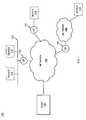
- FIG. 1is an exemplary system 100 in which systems and methods consistent with the present invention may be implemented.
- the system 100includes several devices 110 - 116 and a host server 140 connected to a network 150 .
- the devices 110 - 116may include any mechanism capable of communicating over the network 150 , including, for example, a personal computer, a personal digital assistant (PDA), a cellular or wireless communications device, such as a mobile telephone, etc.
- PDApersonal digital assistant
- cellular or wireless communications devicesuch as a mobile telephone, etc.
- the devices 110 - 116may connect to the network 150 via a customer router 132 - 136 using wired or wireless communication mechanisms.
- devices 110 and 112connect to the network 150 via a local area network (LAN) 122 and a customer router 132 ;
- device 114connects to the network 150 via a customer router 134 using a wired or wireless connection;
- device 116connects to the network 150 via another network 126 , such as the Internet, an intranet, a wide area network (WAN), a LAN, or a similar network, and a customer router 136 .
- FIG. 1shows four devices connected to the network 150 for simplicity.
- WANwide area network
- LANlocal area network
- FIG. 1shows four devices connected to the network 150 for simplicity.
- different numbers of devicesmay connect to the network 150 in a number of different ways.
- the network 150may include a packet routing network of a service provider that may include the Internet, an intranet, a wide area network (WAN), etc.
- FIG. 2is an exemplary diagram of the network 150 consistent with the present invention, including several interconnected backbone points-of-presence (PoPs) 210 - 240 . Each of the PoPs connects to its neighbor PoPs. For example, PoP 210 connects to PoP 220 and PoP 240 . Other configurations are also possible. Four PoPs are shown for simplicity.
- Each of the PoPsincludes one or more backbone routers (BR) 212 - 216 and a server 218 .
- the backbone routersinteract with customer routers and other backbone routers to transmit data through the network 150 .
- FIG. 3is an exemplary diagram of a backbone router 300 , consistent with the present invention, in the network 150 of FIG. 2 .
- the router 300includes several input buffers 310 , several output buffers 320 , a switching fabric 330 , and a controller 340 .
- the input buffers 310temporarily store received packets, and the output buffers 320 temporarily store packets for transmission.
- the switching fabric 330may include a conventional switch fabric to connect the input buffers 310 to the output buffers 320 .
- the controller 340controls the operation of the router 300 .
- the controller 340may include a processor, microprocessor, digital signal processor, etc. that analyzes incoming packets and configures the switching fabric 330 to send the packets to the appropriate output buffers 320 .
- FIG. 4is an exemplary diagram of a server 400 , such as server 218 .
- the server 400includes a bus 410 , a processor 420 , a memory 430 , an input device 440 , an output device 450 , and a communication interface 460 .
- the bus 410permits communication among the components of the server 400 .
- the processor 420may include any type of conventional processor or microprocessor that interprets and executes instructions.
- the memory 430may include a RAM or another dynamic storage device that stores information and instructions for execution by the processor 420 ; a ROM or another type of static storage device that stores static information and instructions for use by the processor 420 ; and/or some other type of magnetic or optical recording medium and its corresponding drive.
- the input device 440may include any conventional mechanism that permits an operator to input information to the server 400 , such as a keyboard, a mouse, a pen, voice recognition and/or biometric mechanisms, etc.
- the output device 450may include any conventional mechanism that outputs information to the operator, including a display, a printer, a pair of speakers, etc.
- the communication interface 460may include any transceiver-like mechanism that enables the server 400 to communicate with a backbone router, such as router 214 ( FIG. 2 ).
- the server 400maintains a list of targets, including other servers in the network 150 , as well as any connected customer routers.
- the server 400determines target connectivity (i.e., reachability) using a pinging process (“pinger”) in combination with an enhanced pinging process (“multiping”) to ping all of the targets on the list.
- pingera pinging process
- multipingan enhanced pinging process
- the server 400may use rules derived from Internet Engineering Task Force (IETF) guidelines (available on their web site at www.ietf.cnri.reston.va.us/home.html) to determine when a particular target is unreachable.
- IETFInternet Engineering Task Force
- the IETF guidelinesspecify, for example, the frequency of pings (e.g., 10 milliseconds), the length of timeouts (e.g., 1 second), and the fraction of pings that must be answered for a target to be declared reachable (e.g., 5-out-of-20).
- the server 400also tracks its own heartbeat signals to determine its own status on a periodic basis at relatively short intervals. Reception of a heartbeat signal indicates to the server 400 whether the absence of a recorded outage was due to a monitoring problem or due to the fact that the outage never took place.
- the server 400may maintain records of results of the pinging, or to conserve storage space, may record only state transitions or status changes (i.e., a transition from reachable to unreachable, or vice versa). Because the recording of state transitions is susceptible to a loss of information and incorrect inferences, the server 400 may verify the status of all the targets on its list on a periodic basis at relatively long intervals.
- FIG. 5is an exemplary diagram of pinging records 500 maintained by the server 400 .
- the records 500include a heartbeat (H-type) record 510 , a status (S-type) record 520 , and an event (E-type) record 530 .
- the heartbeat record 510stores information regarding the heartbeat signals, and may include three fields: a source name 511 , an identifier (ID) 512 , and a timestamp 513 .
- the source name 511indicates the name of the source host (i.e., the server).
- the identifier 512identifies the record as a heartbeat record.
- the timestamp 513indicates a time at which the record was obtained.
- the status record 520stores information regarding the periodic status verifications, and may include five fields: a source name 521 , an identifier (ID) 522 , a timestamp 523 , a target name 524 , and a status 525 .
- the source name 521indicates the name of the source host.
- the identifier 522identifies the record as a status record.
- the timestamp 523indicates a time at which the record was obtained.
- the target name 524indicates the name of the target host (i.e., a target of the pings).
- the status 525indicates whether the target host was reachable or unreachable.
- the event record 530stores information regarding state transitions, and may include five fields: a source name 531 , an identifier (ID) 532 , a timestamp 533 , a target name 534 , and a status 535 .
- the source name 531indicates the name of the source host.
- the identifier 532identifies the record as an event record.
- the timestamp 533indicates a time at which the record was obtained.
- the target name 534indicates the name of the target host (i.e., a target of the pings).
- the status 535indicates whether the target host was reachable or unreachable.
- the host 140periodically collects the results (stored in the pinging records 500 ) from the servers and parses them into individual outage records.
- the host 140may also maintain a “state of the network” record that summarizes occurrences since the last collection period.
- FIG. 6is an exemplary diagram of the host 140 in an implementation consistent with the present invention.
- the host 140includes a bus 610 , a processor 620 , a memory 630 , an input device 640 , an output device 650 , and a communication interface 660 .
- the bus 610permits communication among the components of the host 140 .
- the processor 620may include any type of conventional processor or microprocessor that interprets and executes instructions.
- the memory 630may include a RAM or another dynamic storage device that stores information and instructions for execution by the processor 620 ; a ROM or another type of static storage device that stores static information and instructions for use by the processor 620 ; and/or some other type of magnetic or optical recording medium and its corresponding drive.
- the input device 640may include any conventional mechanism that permits an operator to input information to the host 140 , such as a keyboard, a mouse, a pen, voice recognition and/or biometric mechanisms, etc.
- the output device 650may include any conventional mechanism that outputs information to the operator, including a display, a printer, a pair of speakers, etc.
- the communication interface 660may include any transceiver-like mechanism that enables the host 140 to communicate with other devices and/or systems.
- the communication interface 660may include mechanisms for communicating via a network, such as network 150 ( FIG. 1 ).
- FIG. 7is a flowchart of network monitoring consistent with the present invention.
- the pinger process within each of the serversinteracts with the multiping process to monitor end-to-end connectivity (i.e., reachability).
- the pinger processmay follow the definition given by the IETF for determining whether a target is considered reachable.
- the IETFdefines a target as reachable if at least 5 out of 20 requests have been acknowledged, with a recommended timeout of 10 seconds.
- the pinger processTo monitor network status, the pinger process first obtains a list of targets to be pinged [step 710 ].
- the pinger processmay obtain the list from an automated process (internal or external to the server) designed to monitor network developments and generate the list.
- the targetsinclude other servers in the network 150 and any connected customer routers.
- the pinger processthen initiates the multiping process to perform the actual pinging of the targets [step 720 ].
- the pinger processprovides the muitiping process with a list of targets to be pinged.
- the pinger processmight issue a call, such as
- the multiping processconstructs an array of records with information for each target, and then issues the following sequences [step 730 ]:
- the first set of echo requests(to target- 1 , target- 2 , etc.) will be referred to as sequence 1 , the second set of echo requests as sequence 2 , etc.; the set of all sequences as a cycle; the interval between each consecutive request within each sequence as the inter-packet-gap (ipg); and the interval between the sequences as the inter-sequence interval (i).
- the interval (between sequences)may be defined in one of two ways: (1) as the time between the kth echo request to target- 1 and the (k+1)st echo request to target- 1 ; or (2) as the time between the kth echo request to target-m (i.e., the last target) and the (k+1)st request to target- 1 .
- the call issued by the pinger processmight includes several parameters in the “ ⁇ options>” field of the call.
- the parametersmight include:
- -w ⁇ ms_value>Wait for some number of milliseconds before sending out the first echo request. The main reason for this option is to minimize interference between multiple instances of multiping that start at roughly the same time.
- -s ⁇ ip_address>Source host address. This may be used if the source host is multihomed (i.e., a host with more than one connection to the network).
- the main goal of the multiping processis to multiplex the pings between multiple targets.
- the multiping processissues 10 Internet Control Message Protocol (ICMP) echo requests to a single target with a 1 second interval, and that the implicit timeout is 1 second.
- ICMPInternet Control Message Protocol
- the processkeeps all of the echo requests within the sequence as close to each other as possible. For instance, given 10 targets, if the ipg is set to 10 milliseconds (ms), it will take 100 ms for the multiping process to issue all of the echo requests, leaving 900 ms for reception of echo responses before the next sequence starts.
- the effective timeoutis 900 ms, not 1 second:
- the corresponding request to the multiping processhas the following syntax, assuming there are to be 20 pings to each target and the first definition of the interval (i) is used:
- -cis the sequence count
- -gis the ipg value in ms
- -iis the inter-sequence interval in 20 ms.
- the pinger processmight use the exact interval (-e) flag in its call to the multiping process.
- the callmight take the form of:
- the multiping processinterprets the factor “-i 1000” as 1000 ms between the kth request of the last target and the (k+1)st request to the first target.
- the interval between each sequenceis no longer 1000 ms, but 1000+(ipg*(n ⁇ i)).
- the resultsmight take the form of:
- the statusindicates whether the target is reachable or unreachable. “Reachable” here means that the multiping process received a valid ICMP echo reply, and “unreachable” means that the multiping process received something other than a valid ICMP echo reply (e.g., a timeout or an ICMP bounced).
- the pinger processanalyzes the results from the multiping process to determine whether any of the targets is unreachable [step 740 ]. Each time the pinger process receives results from the multiping process, it checks the 20 most-recent results to determine whether 5 or more requests have been acknowledged in the way of an ICMP echo reply by each of the targets. If 5 or more requests have been acknowledged, then the pinger process declares that target reachable. Otherwise, it declares the target unreachable.
- the pinger processrecords any transitions from reachable to unreachable, and vice versa, as an event in the E-type record 530 ( FIG. 5 ) [step 750 ].
- the advantage of recording only state transitionsis conservation of storage. There is always the risk, however, that a particular transition was missed or not recorded, and that the state of that particular target is, therefore, unknown.
- the pinger processrecords the current state of the targets periodically at relatively long intervals, and stores the information in the S-type record 520 . Also, the lack of a recorded state transition may be due either to the fact that a state transition did not occur or to the fact that there was some sort of failure in the multiping process during the time of the transition.
- the pinger processrecords a heartbeat signal periodically at relatively short intervals, and stores the signal in the H-type record 510 .
- the pinger processtransfers all of its records (H, S, and E-types) to the host 140 for processing [step 760 ].
- the host 140summarizes the records into individual outage records. To do this, the host 140 interprets and then eliminates the cumbersome heartbeat and periodic status records and stores only noteworthy events, such as the absence of a heartbeat or a status change, in memory.
- the host 140may also maintain a “state of the network” file that summarizes the network's status at the end of the previous collection period.
- FIG. 8is a flowchart of claim validation processing consistent with the present invention.
- a customerexperiences an outage as a result of a network malfunction or outage, for example, the customer obtains traceroutes of the path experiencing the malfunction or outage. If the customer does not have the ability to perform the traceroutes from the customer's source host to the destination host, and vice versa, the customer may obtain the traceroutes in a manner described in the previously-incorporated, copending application Ser. No. 09/450,549
- the customersends a claim, including the traceroutes and the time interval in which the outage occurred, to the host 140 [step 810 ].
- the customermay do this, for example, by emailing the claim to the host 140 .
- the host 140parses the traceroutes to determine the paths traveled in the forward (source-to-destination) and reverse (destination-to-source) directions [step 820 ]. The host 140 then generates a list of routers located within each of the paths [step 830 ]. The host 140 uses the list to identify servers associated with the routers. The host 140 then analyzes the records stored in its memory relating to the identified servers to determine whether network performance complied with the SLG [step 840 ].
- the host 140does not determine whether the customer ever suffered an outage, but rather whether the outage lasted at least a predetermined period of time, such as 10 minutes.
- the host 140analyzes the records stored in memory to determine whether the routers in the paths were out for a sustained 10-minute period. Based on its findings, the host 140 determines whether to credit the customer for the outage.
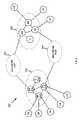
- FIG. 9illustrates an example of the records analyzed by the host 140 to determine whether network performance complied with the SLG.
- customer Aprovides a claim to the host 140 indicating an outage in reaching destination B.
- customer Aconnects to the network 150 via a PoP containing server S 1
- destination Bconnects to the network 150 via a PoP containing server S 2 .
- the host 140pieces together the end-to-end path by analyzing three sets of records for the time period in question: the records corresponding to the path 910 from S 1 to A, the records corresponding to the paths 920 and 930 between S 1 and S 2 ; and the records corresponding to the path 940 from S 2 to B. Based on this information, the host 140 can determine whether network performance complied with the SLG.
- Systems and methods consistent with the present inventionmonitor and validate connectivity service-level guarantees by selectively pinging network resources.
- the preceding descriptionrelates to a reactive system by which the system determines compliance with its SLG in response to a customer claim.
- the descriptionequally applies, however, to proactive systems by which the system continuously monitors network performance to determine compliance with its SLG.
- the host serverperforms the pinging of the network resources.
- the routersping other routers to determine connectivity.
Landscapes
- Engineering & Computer Science (AREA)
- Computer Networks & Wireless Communication (AREA)
- Signal Processing (AREA)
- Data Exchanges In Wide-Area Networks (AREA)
Abstract
Description
| -g <ms_value>: | The inter-packet gap (ipg) value in milliseconds |
| (default = 10 ms) | |
| -j <ms_value>: | The inter-sequence interval value in milliseconds |
| (default = 1000 ms). | |
| -e | The exact interval flag instructs the multiping |
| process to use the second definition of the | |
| inter-sequence value. | |
| -t <ms_value>: | Timeout in milliseconds. All packets received |
| after ‘start of the sequence + timeout value’ | |
| are ignored (default = i). | |
| -w <ms_value>: | Wait for some number of milliseconds before sending |
| out the first echo request. The main reason for this | |
| option is to minimize interference between multiple | |
| instances of multiping that start at roughly the | |
| same time. | |
| -s <ip_address>: | Source host address. This may be used if the source |
| host is multihomed (i.e., a host with more than one | |
| connection to the network). | |

Claims (13)
Priority Applications (1)
| Application Number | Priority Date | Filing Date | Title |
|---|---|---|---|
| US12/256,815US8898279B2 (en) | 1999-11-30 | 2008-10-23 | Connectivity service-level guarantee monitoring and claim validation systems and methods |
Applications Claiming Priority (3)
| Application Number | Priority Date | Filing Date | Title |
|---|---|---|---|
| US09/450,601US6745242B1 (en) | 1999-11-30 | 1999-11-30 | Connectivity service-level guarantee monitoring and claim validation systems and methods |
| US10/279,680US7457859B1 (en) | 1999-11-30 | 2002-10-24 | Connectivity service-level guarantee monitoring and claim validation systems and methods |
| US12/256,815US8898279B2 (en) | 1999-11-30 | 2008-10-23 | Connectivity service-level guarantee monitoring and claim validation systems and methods |
Related Parent Applications (1)
| Application Number | Title | Priority Date | Filing Date |
|---|---|---|---|
| US10/279,680ContinuationUS7457859B1 (en) | 1999-11-30 | 2002-10-24 | Connectivity service-level guarantee monitoring and claim validation systems and methods |
Publications (2)
| Publication Number | Publication Date |
|---|---|
| US20090049170A1 US20090049170A1 (en) | 2009-02-19 |
| US8898279B2true US8898279B2 (en) | 2014-11-25 |
Family
ID=32326697
Family Applications (3)
| Application Number | Title | Priority Date | Filing Date |
|---|---|---|---|
| US09/450,601Expired - LifetimeUS6745242B1 (en) | 1999-11-30 | 1999-11-30 | Connectivity service-level guarantee monitoring and claim validation systems and methods |
| US10/279,680Expired - LifetimeUS7457859B1 (en) | 1999-11-30 | 2002-10-24 | Connectivity service-level guarantee monitoring and claim validation systems and methods |
| US12/256,815Expired - Fee RelatedUS8898279B2 (en) | 1999-11-30 | 2008-10-23 | Connectivity service-level guarantee monitoring and claim validation systems and methods |
Family Applications Before (2)
| Application Number | Title | Priority Date | Filing Date |
|---|---|---|---|
| US09/450,601Expired - LifetimeUS6745242B1 (en) | 1999-11-30 | 1999-11-30 | Connectivity service-level guarantee monitoring and claim validation systems and methods |
| US10/279,680Expired - LifetimeUS7457859B1 (en) | 1999-11-30 | 2002-10-24 | Connectivity service-level guarantee monitoring and claim validation systems and methods |
Country Status (1)
| Country | Link |
|---|---|
| US (3) | US6745242B1 (en) |
Cited By (1)
| Publication number | Priority date | Publication date | Assignee | Title |
|---|---|---|---|---|
| US11153181B1 (en)* | 2019-12-04 | 2021-10-19 | Amazon Technologies, Inc. | Dynamic node reconfiguration and provisioning of network devices |
Families Citing this family (24)
| Publication number | Priority date | Publication date | Assignee | Title |
|---|---|---|---|---|
| WO2001061524A1 (en)* | 2000-02-18 | 2001-08-23 | Cedere Corporation | Method of automatically baselining business bandwidth |
| US20020143911A1 (en)* | 2001-03-30 | 2002-10-03 | John Vicente | Host-based network traffic control system |
| US20020194319A1 (en)* | 2001-06-13 | 2002-12-19 | Ritche Scott D. | Automated operations and service monitoring system for distributed computer networks |
| ES2298537T3 (en)* | 2002-02-20 | 2008-05-16 | Pharos Systems International, Inc. | SYSTEM FOR MONITORING THE USE AND RESERVATION OF COMPUTERS AND RELATED PROCEDURES. |
| US6931356B2 (en)* | 2002-03-21 | 2005-08-16 | International Business Machines Corporation | System for dynamically adjusting performance measurements according to provided service level |
| US6928394B2 (en)* | 2002-03-21 | 2005-08-09 | International Business Machines Corporation | Method for dynamically adjusting performance measurements according to provided service level |
| US7937460B2 (en)* | 2003-07-11 | 2011-05-03 | Computer Associates Think, Inc. | System and method for providing service level management |
| US8949380B2 (en)* | 2003-09-29 | 2015-02-03 | Eqapez Foundation, L.L.C. | Method and system for distributing images to client systems |
| US20060004697A1 (en)* | 2004-06-09 | 2006-01-05 | Lipsky Scott E | Method and system for restricting the display of images |
| JP2006033315A (en)* | 2004-07-15 | 2006-02-02 | Evolium Sas | Network monitoring system |
| US7814195B2 (en)* | 2004-09-10 | 2010-10-12 | Sony Corporation | Method for data synchronization with mobile wireless devices |
| JP2006086654A (en)* | 2004-09-14 | 2006-03-30 | Canon Inc | Imaging device |
| US20060143090A1 (en)* | 2004-12-27 | 2006-06-29 | Barry Ridings | Method and system for identifying wireless network coverage gaps |
| US7519074B2 (en)* | 2005-02-22 | 2009-04-14 | Level 3 Communications, Llc | Voice call coordinator |
| US7436936B2 (en)* | 2005-02-22 | 2008-10-14 | Level 3 Communications, Llc | VoIP call through tester |
| US7609825B2 (en)* | 2005-07-11 | 2009-10-27 | At&T Intellectual Property I, L.P. | Method and apparatus for automated billing and crediting of customer accounts |
| JP5157778B2 (en)* | 2008-09-18 | 2013-03-06 | 富士通株式会社 | Monitoring device, monitoring method, and computer program |
| US20110011999A1 (en)* | 2009-07-14 | 2011-01-20 | Rafael Wischkin | Hanging hook |
| US20120131181A1 (en)* | 2010-11-23 | 2012-05-24 | International Business Machines Corporation | Workload management in heterogeneous environments |
| US9838319B2 (en)* | 2011-09-26 | 2017-12-05 | Wilmerding Communications Llc | Encapsulation system featuring an intelligent network component |
| EP3039822A1 (en)* | 2013-08-30 | 2016-07-06 | Hewlett Packard Enterprise Development LP | Network element status identification based on service |
| TWI538441B (en)* | 2013-11-05 | 2016-06-11 | 衛信科技有限公司 | Processing system and method for constructing network structure deployment diagram and computer program product for deploying analysis program of internal storage network structure |
| KR102161443B1 (en)* | 2013-12-20 | 2020-10-06 | 삼성전자 주식회사 | Discovering and controlling method and apparatus of controllee in a smart home system |
| US10904096B2 (en)* | 2018-12-21 | 2021-01-26 | Cisco Technology, Inc. | Deep network path analysis for identifying network segments affecting application performance |
Citations (34)
| Publication number | Priority date | Publication date | Assignee | Title |
|---|---|---|---|---|
| US5664170A (en)* | 1990-05-07 | 1997-09-02 | Next Computer, Inc. | Flexible distributed network database containing configuration information for a network divided into domains |
| US5930476A (en) | 1996-05-29 | 1999-07-27 | Sun Microsystems, Inc. | Apparatus and method for generating automatic customized event requests |
| US6006016A (en) | 1994-11-10 | 1999-12-21 | Bay Networks, Inc. | Network fault correlation |
| US6006017A (en) | 1995-05-02 | 1999-12-21 | Motorola Inc. | System for determining the frequency of repetitions of polling active stations relative to the polling of inactive stations |
| US6058102A (en) | 1997-11-07 | 2000-05-02 | Visual Networks Technologies, Inc. | Method and apparatus for performing service level analysis of communications network performance metrics |
| US6065139A (en) | 1997-03-31 | 2000-05-16 | International Business Machines Corporation | Method and system for surveillance of computer system operations |
| US6145089A (en) | 1997-11-10 | 2000-11-07 | Legato Systems, Inc. | Server fail-over system |
| US6169881B1 (en)* | 1998-05-04 | 2001-01-02 | Motorola, Inc. | Method and apparatus for predicting impending service outages for ground-to-satellite terminal in a satellite communication system |
| US6170009B1 (en) | 1998-07-17 | 2001-01-02 | Kallol Mandal | Controlling devices on a network through policies |
| US6195697B1 (en) | 1999-06-02 | 2001-02-27 | Ac Properties B.V. | System, method and article of manufacture for providing a customer interface in a hybrid network |
| US6205481B1 (en)* | 1998-03-17 | 2001-03-20 | Infolibria, Inc. | Protocol for distributing fresh content among networked cache servers |
| US6233619B1 (en)* | 1998-07-31 | 2001-05-15 | Unisys Corporation | Virtual transport layer interface and messaging subsystem for high-speed communications between heterogeneous computer systems |
| US6256747B1 (en) | 1997-09-25 | 2001-07-03 | Hitachi, Ltd. | Method of managing distributed servers and distributed information processing system using the method |
| US6298454B1 (en) | 1999-02-22 | 2001-10-02 | Fisher-Rosemount Systems, Inc. | Diagnostics in a process control system |
| US6321264B1 (en) | 1998-08-28 | 2001-11-20 | 3Com Corporation | Network-performance statistics using end-node computer systems |
| US6363053B1 (en) | 1999-02-08 | 2002-03-26 | 3Com Corporation | Method and apparatus for measurement-based conformance testing of service level agreements in networks |
| US6366563B1 (en) | 1999-12-22 | 2002-04-02 | Mci Worldcom, Inc. | Method, computer program product, and apparatus for collecting service level agreement statistics in a communication network |
| US6370586B2 (en) | 1998-10-30 | 2002-04-09 | Intel Corporation | Monitoring of an electronic device with a system management controller |
| US6425008B1 (en) | 1999-02-16 | 2002-07-23 | Electronic Data Systems Corporation | System and method for remote management of private networks having duplicate network addresses |
| US6430711B1 (en) | 1998-01-06 | 2002-08-06 | Seiko Epson Corporation | System and method for monitoring the state of a plurality of machines connected via a computer network |
| US6477590B1 (en) | 1998-04-01 | 2002-11-05 | Microsoft Corporation | Method and system for message transfer session management |
| US6493348B1 (en)* | 1997-12-05 | 2002-12-10 | Telcordia Technologies, Inc. | XDSL-based internet access router |
| US6513060B1 (en) | 1998-08-27 | 2003-01-28 | Internetseer.Com Corp. | System and method for monitoring informational resources |
| US6539427B1 (en) | 1999-06-29 | 2003-03-25 | Cisco Technology, Inc. | Dynamically adaptive network element in a feedback-based data network |
| US6542466B1 (en) | 1999-05-20 | 2003-04-01 | Motorola, Inc. | Communication network method and apparatus |
| US6556659B1 (en)* | 1999-06-02 | 2003-04-29 | Accenture Llp | Service level management in a hybrid network architecture |
| US6563793B1 (en)* | 1998-11-25 | 2003-05-13 | Enron Warpspeed Services, Inc. | Method and apparatus for providing guaranteed quality/class of service within and across networks using existing reservation protocols and frame formats |
| US6591298B1 (en)* | 2000-04-24 | 2003-07-08 | Keynote Systems, Inc. | Method and system for scheduling measurement of site performance over the internet |
| US6606663B1 (en)* | 1998-09-29 | 2003-08-12 | Openwave Systems Inc. | Method and apparatus for caching credentials in proxy servers for wireless user agents |
| US6643612B1 (en) | 2001-06-28 | 2003-11-04 | Atrica Ireland Limited | Mechanism and protocol for per connection based service level agreement measurement |
| US6768787B1 (en) | 1993-02-16 | 2004-07-27 | C & P Of Virginia | Common channeling signaling network maintenance and testing |
| US6795400B1 (en) | 1999-11-30 | 2004-09-21 | Verizon Corporate Services Group Inc. | Packet loss service-level guarantee monitoring and claim validation systems and methods |
| US20080126178A1 (en)* | 2005-09-10 | 2008-05-29 | Moore James F | Surge-Based Online Advertising |
| US20090086642A1 (en)* | 2007-09-28 | 2009-04-02 | Cisco Technology, Inc. | High availability path audit |
- 1999
- 1999-11-30USUS09/450,601patent/US6745242B1/ennot_activeExpired - Lifetime
- 2002
- 2002-10-24USUS10/279,680patent/US7457859B1/ennot_activeExpired - Lifetime
- 2008
- 2008-10-23USUS12/256,815patent/US8898279B2/ennot_activeExpired - Fee Related
Patent Citations (34)
| Publication number | Priority date | Publication date | Assignee | Title |
|---|---|---|---|---|
| US5664170A (en)* | 1990-05-07 | 1997-09-02 | Next Computer, Inc. | Flexible distributed network database containing configuration information for a network divided into domains |
| US6768787B1 (en) | 1993-02-16 | 2004-07-27 | C & P Of Virginia | Common channeling signaling network maintenance and testing |
| US6006016A (en) | 1994-11-10 | 1999-12-21 | Bay Networks, Inc. | Network fault correlation |
| US6006017A (en) | 1995-05-02 | 1999-12-21 | Motorola Inc. | System for determining the frequency of repetitions of polling active stations relative to the polling of inactive stations |
| US5930476A (en) | 1996-05-29 | 1999-07-27 | Sun Microsystems, Inc. | Apparatus and method for generating automatic customized event requests |
| US6065139A (en) | 1997-03-31 | 2000-05-16 | International Business Machines Corporation | Method and system for surveillance of computer system operations |
| US6256747B1 (en) | 1997-09-25 | 2001-07-03 | Hitachi, Ltd. | Method of managing distributed servers and distributed information processing system using the method |
| US6058102A (en) | 1997-11-07 | 2000-05-02 | Visual Networks Technologies, Inc. | Method and apparatus for performing service level analysis of communications network performance metrics |
| US6145089A (en) | 1997-11-10 | 2000-11-07 | Legato Systems, Inc. | Server fail-over system |
| US6493348B1 (en)* | 1997-12-05 | 2002-12-10 | Telcordia Technologies, Inc. | XDSL-based internet access router |
| US6430711B1 (en) | 1998-01-06 | 2002-08-06 | Seiko Epson Corporation | System and method for monitoring the state of a plurality of machines connected via a computer network |
| US6205481B1 (en)* | 1998-03-17 | 2001-03-20 | Infolibria, Inc. | Protocol for distributing fresh content among networked cache servers |
| US6477590B1 (en) | 1998-04-01 | 2002-11-05 | Microsoft Corporation | Method and system for message transfer session management |
| US6169881B1 (en)* | 1998-05-04 | 2001-01-02 | Motorola, Inc. | Method and apparatus for predicting impending service outages for ground-to-satellite terminal in a satellite communication system |
| US6170009B1 (en) | 1998-07-17 | 2001-01-02 | Kallol Mandal | Controlling devices on a network through policies |
| US6233619B1 (en)* | 1998-07-31 | 2001-05-15 | Unisys Corporation | Virtual transport layer interface and messaging subsystem for high-speed communications between heterogeneous computer systems |
| US6513060B1 (en) | 1998-08-27 | 2003-01-28 | Internetseer.Com Corp. | System and method for monitoring informational resources |
| US6321264B1 (en) | 1998-08-28 | 2001-11-20 | 3Com Corporation | Network-performance statistics using end-node computer systems |
| US6606663B1 (en)* | 1998-09-29 | 2003-08-12 | Openwave Systems Inc. | Method and apparatus for caching credentials in proxy servers for wireless user agents |
| US6370586B2 (en) | 1998-10-30 | 2002-04-09 | Intel Corporation | Monitoring of an electronic device with a system management controller |
| US6563793B1 (en)* | 1998-11-25 | 2003-05-13 | Enron Warpspeed Services, Inc. | Method and apparatus for providing guaranteed quality/class of service within and across networks using existing reservation protocols and frame formats |
| US6363053B1 (en) | 1999-02-08 | 2002-03-26 | 3Com Corporation | Method and apparatus for measurement-based conformance testing of service level agreements in networks |
| US6425008B1 (en) | 1999-02-16 | 2002-07-23 | Electronic Data Systems Corporation | System and method for remote management of private networks having duplicate network addresses |
| US6298454B1 (en) | 1999-02-22 | 2001-10-02 | Fisher-Rosemount Systems, Inc. | Diagnostics in a process control system |
| US6542466B1 (en) | 1999-05-20 | 2003-04-01 | Motorola, Inc. | Communication network method and apparatus |
| US6556659B1 (en)* | 1999-06-02 | 2003-04-29 | Accenture Llp | Service level management in a hybrid network architecture |
| US6195697B1 (en) | 1999-06-02 | 2001-02-27 | Ac Properties B.V. | System, method and article of manufacture for providing a customer interface in a hybrid network |
| US6539427B1 (en) | 1999-06-29 | 2003-03-25 | Cisco Technology, Inc. | Dynamically adaptive network element in a feedback-based data network |
| US6795400B1 (en) | 1999-11-30 | 2004-09-21 | Verizon Corporate Services Group Inc. | Packet loss service-level guarantee monitoring and claim validation systems and methods |
| US6366563B1 (en) | 1999-12-22 | 2002-04-02 | Mci Worldcom, Inc. | Method, computer program product, and apparatus for collecting service level agreement statistics in a communication network |
| US6591298B1 (en)* | 2000-04-24 | 2003-07-08 | Keynote Systems, Inc. | Method and system for scheduling measurement of site performance over the internet |
| US6643612B1 (en) | 2001-06-28 | 2003-11-04 | Atrica Ireland Limited | Mechanism and protocol for per connection based service level agreement measurement |
| US20080126178A1 (en)* | 2005-09-10 | 2008-05-29 | Moore James F | Surge-Based Online Advertising |
| US20090086642A1 (en)* | 2007-09-28 | 2009-04-02 | Cisco Technology, Inc. | High availability path audit |
Non-Patent Citations (4)
| Title |
|---|
| Calkins, "MultiPing-Versoin 1.3," http://members.xoom.com/dcalkins/multiping.htm, three pages, Jan. 22, 1999. |
| Calkins, "MultiPing—Versoin 1.3," http://members.xoom.com/dcalkins/multiping.htm, three pages, Jan. 22, 1999. |
| Christias, "Ping-Send ICMP ECHO-Request Packets to Network Hosts," http://www.unidata.ucar.edu/cgi-bin/man-cgi?ping+8, four pages, Jun. 12, 1997. |
| Christias, "Ping—Send ICMP ECHO—Request Packets to Network Hosts," http://www.unidata.ucar.edu/cgi-bin/man-cgi?ping+8, four pages, Jun. 12, 1997. |
Cited By (1)
| Publication number | Priority date | Publication date | Assignee | Title |
|---|---|---|---|---|
| US11153181B1 (en)* | 2019-12-04 | 2021-10-19 | Amazon Technologies, Inc. | Dynamic node reconfiguration and provisioning of network devices |
Also Published As
| Publication number | Publication date |
|---|---|
| US6745242B1 (en) | 2004-06-01 |
| US20090049170A1 (en) | 2009-02-19 |
| US7457859B1 (en) | 2008-11-25 |
Similar Documents
| Publication | Publication Date | Title |
|---|---|---|
| US8898279B2 (en) | Connectivity service-level guarantee monitoring and claim validation systems and methods | |
| US10652765B2 (en) | Automated network diagnostic techniques | |
| US6970924B1 (en) | Methods and apparatus for monitoring end-user experience in a distributed network | |
| Xu et al. | Finding service paths in a media service proxy network | |
| US7698460B2 (en) | Peer-to-peer method of quality of service (QoS) probing and analysis and infrastructure employing same | |
| US8320261B2 (en) | Method and apparatus for troubleshooting subscriber issues on a telecommunications network | |
| CN101815000B (en) | Methods and apparatus for determining and displaying wan optimization attributes for individual transactions | |
| US8839325B2 (en) | System and method of managing video content quality | |
| US8270309B1 (en) | Systems for monitoring delivery performance of a packet flow between reference nodes | |
| CN101036330B (en) | Systems and methods for detecting network faults | |
| US7995574B2 (en) | Detection of forwarding problems for external prefixes | |
| US20100008250A1 (en) | Method and apparatus for measuring packet transmission quality | |
| US20060029016A1 (en) | Debugging application performance over a network | |
| US20110283134A1 (en) | Server Checking Using Health Probe Chaining | |
| US20100039955A1 (en) | Systems and methods to monitor communications to identify a communications problem | |
| US10333724B2 (en) | Method and system for low-overhead latency profiling | |
| US9137305B2 (en) | Information processing device, computer-readable recording medium, and control method | |
| JP2003283565A (en) | System for end user monitoring of network service conditions across heterogeneous networks | |
| US6795400B1 (en) | Packet loss service-level guarantee monitoring and claim validation systems and methods | |
| US9059904B2 (en) | Method and system for intermediate node to locate a fault independently | |
| CN110224883A (en) | A kind of Grey Fault Diagnosis method applied to telecommunications bearer network | |
| US8248934B2 (en) | Methods and apparatus for determining and displaying a transaction reset metric | |
| US8295178B2 (en) | Manual configuration for sites that cannot give read/write credentials to a voice over internet protocol (VOIP) monitor | |
| US7554929B1 (en) | Mobility aware performance evaluation | |
| US7391739B1 (en) | System and method for creating a frame relay port mirror |
Legal Events
| Date | Code | Title | Description |
|---|---|---|---|
| AS | Assignment | Owner name:BBN TECHNOLOGIES CORP., MASSACHUSETTS Free format text:MERGER;ASSIGNOR:BBNT SOLUTIONS LLC;REEL/FRAME:032637/0652 Effective date:20060103 Owner name:RAYTHEON BBN TECHNOLOGIES CORP., MASSACHUSETTS Free format text:CHANGE OF NAME;ASSIGNOR:BBN TECHNOLOGIES CORP.;REEL/FRAME:032643/0695 Effective date:20091027 Owner name:GENUITY INC., MASSACHUSETTS Free format text:CHANGE OF NAME;ASSIGNOR:GTE INTERNETWORKING INCORPORATED;REEL/FRAME:032643/0054 Effective date:20000406 Owner name:GTE SERVICE CORPORATION, TEXAS Free format text:ASSIGNMENT OF ASSIGNORS INTEREST;ASSIGNOR:GENUITY INC.;REEL/FRAME:032636/0866 Effective date:20000906 Owner name:GENUITY INC., MASSACHUSETTS Free format text:ASSIGNMENT OF ASSIGNORS INTEREST;ASSIGNOR:GENUITY INC.;REEL/FRAME:032636/0866 Effective date:20000906 Owner name:VERIZON CORPORATE SERVICES GROUP INC., NEW JERSEY Free format text:ASSIGNMENT OF ASSIGNORS INTEREST;ASSIGNOR:VERIZON CORPORATE SERVICES GROUP INC.;REEL/FRAME:032637/0490 Effective date:20040420 Owner name:VERIZON CORPORATE SERVICES GROUP INC., NEW JERSEY Free format text:CHANGE OF NAME;ASSIGNOR:GTE SERVICE CORPORATION;REEL/FRAME:032636/0982 Effective date:20011211 Owner name:BBNT SOLUTIONS LLC, MASSACHUSETTS Free format text:ASSIGNMENT OF ASSIGNORS INTEREST;ASSIGNOR:VERIZON CORPORATE SERVICES GROUP INC.;REEL/FRAME:032637/0490 Effective date:20040420 Owner name:GTE INTERNETWORKING INCORPORATED, MASSACHUSETTS Free format text:ASSIGNMENT OF ASSIGNORS INTEREST;ASSIGNORS:SCHICK, IRVIN C.;HERSH, GREGORY;REEL/FRAME:032636/0619 Effective date:19991129 Owner name:LEVEL 3 COMMUNICATIONS, LLC, COLORADO Free format text:ASSIGNMENT OF ASSIGNORS INTEREST;ASSIGNOR:GENUITY INC.;REEL/FRAME:032662/0855 Effective date:20030204 | |
| STCF | Information on status: patent grant | Free format text:PATENTED CASE | |
| FEPP | Fee payment procedure | Free format text:SURCHARGE FOR LATE PAYMENT, LARGE ENTITY (ORIGINAL EVENT CODE: M1554) | |
| MAFP | Maintenance fee payment | Free format text:PAYMENT OF MAINTENANCE FEE, 4TH YEAR, LARGE ENTITY (ORIGINAL EVENT CODE: M1551) Year of fee payment:4 | |
| FEPP | Fee payment procedure | Free format text:MAINTENANCE FEE REMINDER MAILED (ORIGINAL EVENT CODE: REM.); ENTITY STATUS OF PATENT OWNER: LARGE ENTITY | |
| LAPS | Lapse for failure to pay maintenance fees | Free format text:PATENT EXPIRED FOR FAILURE TO PAY MAINTENANCE FEES (ORIGINAL EVENT CODE: EXP.); ENTITY STATUS OF PATENT OWNER: LARGE ENTITY | |
| STCH | Information on status: patent discontinuation | Free format text:PATENT EXPIRED DUE TO NONPAYMENT OF MAINTENANCE FEES UNDER 37 CFR 1.362 | |
| FP | Lapsed due to failure to pay maintenance fee | Effective date:20221125 |