US8897326B2 - Pump energy wavelength stabilization - Google Patents
Pump energy wavelength stabilizationDownload PDFInfo
- Publication number
- US8897326B2 US8897326B2US12/555,329US55532909AUS8897326B2US 8897326 B2US8897326 B2US 8897326B2US 55532909 AUS55532909 AUS 55532909AUS 8897326 B2US8897326 B2US 8897326B2
- Authority
- US
- United States
- Prior art keywords
- pump energy
- absorption coefficient
- gain medium
- operating wavelength
- wavelength
- Prior art date
- Legal status (The legal status is an assumption and is not a legal conclusion. Google has not performed a legal analysis and makes no representation as to the accuracy of the status listed.)
- Active, expires
Links
- 230000006641stabilisationEffects0.000titledescription3
- 238000011105stabilizationMethods0.000titledescription3
- 238000010521absorption reactionMethods0.000claimsabstractdescription64
- 238000000034methodMethods0.000claimsabstractdescription21
- JNDMLEXHDPKVFC-UHFFFAOYSA-Naluminum;oxygen(2-);yttrium(3+)Chemical compound[O-2].[O-2].[O-2].[Al+3].[Y+3]JNDMLEXHDPKVFC-UHFFFAOYSA-N0.000claimsdescription22
- 229910019901yttrium aluminum garnetInorganic materials0.000claimsdescription22
- 239000013078crystalSubstances0.000claimsdescription11
- QEFYFXOXNSNQGX-UHFFFAOYSA-Nneodymium atomChemical group[Nd]QEFYFXOXNSNQGX-UHFFFAOYSA-N0.000claimsdescription6
- 230000000087stabilizing effectEffects0.000claimsdescription2
- 238000006243chemical reactionMethods0.000description5
- 229910052779NeodymiumInorganic materials0.000description4
- 238000005086pumpingMethods0.000description4
- 230000007423decreaseEffects0.000description3
- 230000008901benefitEffects0.000description2
- 238000010586diagramMethods0.000description2
- 239000002019doping agentSubstances0.000description2
- 230000003287optical effectEffects0.000description2
- RIUWBIIVUYSTCN-UHFFFAOYSA-Ntrilithium borateChemical compound[Li+].[Li+].[Li+].[O-]B([O-])[O-]RIUWBIIVUYSTCN-UHFFFAOYSA-N0.000description2
- 102000001554HemoglobinsHuman genes0.000description1
- 108010054147HemoglobinsProteins0.000description1
- 229910017502Nd:YVO4Inorganic materials0.000description1
- 230000002411adverseEffects0.000description1
- 239000008280bloodSubstances0.000description1
- 210000004369bloodAnatomy0.000description1
- 238000001816coolingMethods0.000description1
- 230000001419dependent effectEffects0.000description1
- 230000006870functionEffects0.000description1
- 238000003384imaging methodMethods0.000description1
- 230000010287polarizationEffects0.000description1
- WYOHGPUPVHHUGO-UHFFFAOYSA-Kpotassium;oxygen(2-);titanium(4+);phosphateChemical compound[O-2].[K+].[Ti+4].[O-]P([O-])([O-])=OWYOHGPUPVHHUGO-UHFFFAOYSA-K0.000description1
- 230000008646thermal stressEffects0.000description1
- FRNOGLGSGLTDKL-UHFFFAOYSA-Nthulium atomChemical group[Tm]FRNOGLGSGLTDKL-UHFFFAOYSA-N0.000description1
- QWVYNEUUYROOSZ-UHFFFAOYSA-Ntrioxido(oxo)vanadium;yttrium(3+)Chemical compound[Y+3].[O-][V]([O-])([O-])=OQWVYNEUUYROOSZ-UHFFFAOYSA-N0.000description1
- 230000002792vascularEffects0.000description1
- XLYOFNOQVPJJNP-UHFFFAOYSA-NwaterSubstancesOXLYOFNOQVPJJNP-UHFFFAOYSA-N0.000description1
Images
Classifications
- H—ELECTRICITY
- H01—ELECTRIC ELEMENTS
- H01S—DEVICES USING THE PROCESS OF LIGHT AMPLIFICATION BY STIMULATED EMISSION OF RADIATION [LASER] TO AMPLIFY OR GENERATE LIGHT; DEVICES USING STIMULATED EMISSION OF ELECTROMAGNETIC RADIATION IN WAVE RANGES OTHER THAN OPTICAL
- H01S3/00—Lasers, i.e. devices using stimulated emission of electromagnetic radiation in the infrared, visible or ultraviolet wave range
- H01S3/09—Processes or apparatus for excitation, e.g. pumping
- H01S3/091—Processes or apparatus for excitation, e.g. pumping using optical pumping
- H01S3/094—Processes or apparatus for excitation, e.g. pumping using optical pumping by coherent light
- H01S3/0941—Processes or apparatus for excitation, e.g. pumping using optical pumping by coherent light of a laser diode
- H01S3/09415—Processes or apparatus for excitation, e.g. pumping using optical pumping by coherent light of a laser diode the pumping beam being parallel to the lasing mode of the pumped medium, e.g. end-pumping
- H—ELECTRICITY
- H01—ELECTRIC ELEMENTS
- H01S—DEVICES USING THE PROCESS OF LIGHT AMPLIFICATION BY STIMULATED EMISSION OF RADIATION [LASER] TO AMPLIFY OR GENERATE LIGHT; DEVICES USING STIMULATED EMISSION OF ELECTROMAGNETIC RADIATION IN WAVE RANGES OTHER THAN OPTICAL
- H01S3/00—Lasers, i.e. devices using stimulated emission of electromagnetic radiation in the infrared, visible or ultraviolet wave range
- H01S3/09—Processes or apparatus for excitation, e.g. pumping
- H01S3/091—Processes or apparatus for excitation, e.g. pumping using optical pumping
- H01S3/0912—Electronics or drivers for the pump source, i.e. details of drivers or circuitry specific for laser pumping
- H—ELECTRICITY
- H01—ELECTRIC ELEMENTS
- H01S—DEVICES USING THE PROCESS OF LIGHT AMPLIFICATION BY STIMULATED EMISSION OF RADIATION [LASER] TO AMPLIFY OR GENERATE LIGHT; DEVICES USING STIMULATED EMISSION OF ELECTROMAGNETIC RADIATION IN WAVE RANGES OTHER THAN OPTICAL
- H01S3/00—Lasers, i.e. devices using stimulated emission of electromagnetic radiation in the infrared, visible or ultraviolet wave range
- H01S3/10—Controlling the intensity, frequency, phase, polarisation or direction of the emitted radiation, e.g. switching, gating, modulating or demodulating
- H01S3/13—Stabilisation of laser output parameters, e.g. frequency or amplitude
- H—ELECTRICITY
- H01—ELECTRIC ELEMENTS
- H01S—DEVICES USING THE PROCESS OF LIGHT AMPLIFICATION BY STIMULATED EMISSION OF RADIATION [LASER] TO AMPLIFY OR GENERATE LIGHT; DEVICES USING STIMULATED EMISSION OF ELECTROMAGNETIC RADIATION IN WAVE RANGES OTHER THAN OPTICAL
- H01S3/00—Lasers, i.e. devices using stimulated emission of electromagnetic radiation in the infrared, visible or ultraviolet wave range
- H01S3/02—Constructional details
- H01S3/04—Arrangements for thermal management
- H01S3/0407—Liquid cooling, e.g. by water
- H—ELECTRICITY
- H01—ELECTRIC ELEMENTS
- H01S—DEVICES USING THE PROCESS OF LIGHT AMPLIFICATION BY STIMULATED EMISSION OF RADIATION [LASER] TO AMPLIFY OR GENERATE LIGHT; DEVICES USING STIMULATED EMISSION OF ELECTROMAGNETIC RADIATION IN WAVE RANGES OTHER THAN OPTICAL
- H01S3/00—Lasers, i.e. devices using stimulated emission of electromagnetic radiation in the infrared, visible or ultraviolet wave range
- H01S3/05—Construction or shape of optical resonators; Accommodation of active medium therein; Shape of active medium
- H01S3/08—Construction or shape of optical resonators or components thereof
- H01S3/081—Construction or shape of optical resonators or components thereof comprising three or more reflectors
- H01S3/0813—Configuration of resonator
- H01S3/0816—Configuration of resonator having 4 reflectors, e.g. Z-shaped resonators
- H—ELECTRICITY
- H01—ELECTRIC ELEMENTS
- H01S—DEVICES USING THE PROCESS OF LIGHT AMPLIFICATION BY STIMULATED EMISSION OF RADIATION [LASER] TO AMPLIFY OR GENERATE LIGHT; DEVICES USING STIMULATED EMISSION OF ELECTROMAGNETIC RADIATION IN WAVE RANGES OTHER THAN OPTICAL
- H01S3/00—Lasers, i.e. devices using stimulated emission of electromagnetic radiation in the infrared, visible or ultraviolet wave range
- H01S3/10—Controlling the intensity, frequency, phase, polarisation or direction of the emitted radiation, e.g. switching, gating, modulating or demodulating
- H01S3/10069—Memorized or pre-programmed characteristics, e.g. look-up table [LUT]
- H—ELECTRICITY
- H01—ELECTRIC ELEMENTS
- H01S—DEVICES USING THE PROCESS OF LIGHT AMPLIFICATION BY STIMULATED EMISSION OF RADIATION [LASER] TO AMPLIFY OR GENERATE LIGHT; DEVICES USING STIMULATED EMISSION OF ELECTROMAGNETIC RADIATION IN WAVE RANGES OTHER THAN OPTICAL
- H01S3/00—Lasers, i.e. devices using stimulated emission of electromagnetic radiation in the infrared, visible or ultraviolet wave range
- H01S3/10—Controlling the intensity, frequency, phase, polarisation or direction of the emitted radiation, e.g. switching, gating, modulating or demodulating
- H01S3/106—Controlling the intensity, frequency, phase, polarisation or direction of the emitted radiation, e.g. switching, gating, modulating or demodulating by controlling devices placed within the cavity
- H01S3/108—Controlling the intensity, frequency, phase, polarisation or direction of the emitted radiation, e.g. switching, gating, modulating or demodulating by controlling devices placed within the cavity using non-linear optical devices, e.g. exhibiting Brillouin or Raman scattering
- H01S3/109—Frequency multiplication, e.g. harmonic generation
- H—ELECTRICITY
- H01—ELECTRIC ELEMENTS
- H01S—DEVICES USING THE PROCESS OF LIGHT AMPLIFICATION BY STIMULATED EMISSION OF RADIATION [LASER] TO AMPLIFY OR GENERATE LIGHT; DEVICES USING STIMULATED EMISSION OF ELECTROMAGNETIC RADIATION IN WAVE RANGES OTHER THAN OPTICAL
- H01S3/00—Lasers, i.e. devices using stimulated emission of electromagnetic radiation in the infrared, visible or ultraviolet wave range
- H01S3/10—Controlling the intensity, frequency, phase, polarisation or direction of the emitted radiation, e.g. switching, gating, modulating or demodulating
- H01S3/11—Mode locking; Q-switching; Other giant-pulse techniques, e.g. cavity dumping
- H01S3/1123—Q-switching
- H—ELECTRICITY
- H01—ELECTRIC ELEMENTS
- H01S—DEVICES USING THE PROCESS OF LIGHT AMPLIFICATION BY STIMULATED EMISSION OF RADIATION [LASER] TO AMPLIFY OR GENERATE LIGHT; DEVICES USING STIMULATED EMISSION OF ELECTROMAGNETIC RADIATION IN WAVE RANGES OTHER THAN OPTICAL
- H01S3/00—Lasers, i.e. devices using stimulated emission of electromagnetic radiation in the infrared, visible or ultraviolet wave range
- H01S3/10—Controlling the intensity, frequency, phase, polarisation or direction of the emitted radiation, e.g. switching, gating, modulating or demodulating
- H01S3/13—Stabilisation of laser output parameters, e.g. frequency or amplitude
- H01S3/131—Stabilisation of laser output parameters, e.g. frequency or amplitude by controlling the active medium, e.g. by controlling the processes or apparatus for excitation
- H01S3/1312—Stabilisation of laser output parameters, e.g. frequency or amplitude by controlling the active medium, e.g. by controlling the processes or apparatus for excitation by controlling the optical pumping
Definitions
- Embodiments of the inventionare directed to the stabilization of the wavelength of the pump energy while pumping a laser gain medium.
- Laser systemsgenerally include a pump module, a gain medium and a laser resonator.
- the pump moduleincludes laser diodes or bars that generate pump energy.
- the gain mediumabsorbs the pump energy and emits laser light responsive to the absorbed energy.
- the laser resonatorin some designs, operates to generate a harmonic of the laser light.
- the gain mediumis generally tuned to absorb pump energy having a wavelength that is within a specified operating band.
- the wavelength of the pump energymust be carefully controlled to ensure proper operation of the laser system.
- a yttrium-aluminum-garnet crystal (YAG) rod with neodymium atoms (i.e., a Nd:YAG gain medium) using pump energy having a wavelength of 885 nmhas become a desirable pumping scheme due to its natural efficiency gains that can save on cost and electrical/cooling requirements.
- the operating wavelength band of the Nd:YAG gain medium around the 885 nm wavelengthis very narrow.
- Small changes in the wavelength of the pump energycan cause rapid decreases in the absorption efficiency of the gain medium.
- the wavelength shift in the pump energy away from the narrow operating bandwidth of the Nd:YAG gain medium around 885 nmcan also destabilize the wavelength of the pump energy causing it to further deviate from the operating wavelength range of the gain medium.
- VBGVariable Bragg Grating
- Embodiments of the inventionare directed to a method and a laser system in which the wavelength of the pump module is stabilized while pumping the gain medium.
- a gain mediumis provided having an absorption coefficient that varies with wavelength.
- An absorption coefficient curve of the absorption coefficient over a range of wavelengthscomprises peaks and valleys.
- a pump moduleis operated to output pump energy at an operating wavelength within one of the valleys, at which the absorption coefficient is approximately less than 40% of the absorption coefficient at an adjacent peak of the absorption coefficient curve defining the valley.
- the pump energyis directed through the gain medium.
- a portion of the pump energyis absorbed with the gain medium and laser light is emitted from the gain medium responsive to the absorbed pump energy.
- the non-absorbed pump energy(feedback pump energy) is fed back to the pump module.
- the operating wavelength of the pump energyis stabilized using the feedback pump energy.
- the laser systemcomprises a pump module, a gain medium and a reflector.
- the pump moduleoutputs pump energy at an operating wavelength.
- the gain mediumis configured to absorb the pump energy and emit laser light responsive to the absorbed pump energy.
- the absorption coefficient of the gain mediumhas a magnitude that varies with wavelength.
- the absorption coefficient curve of the absorption coefficient over a range of wavelengthscomprises peaks and valleys.
- the operating wavelength of the pump energyis within a valley of the absorption coefficient curve, at which the absorption coefficient is approximately at a minimum within the valley.
- the reflectoris within the path of the pump energy and is configured to direct the non-absorbed portion of the pump energy back to the pump module.
- FIG. 1illustrates a high-power laser system in accordance with embodiments of the invention.
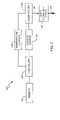
- FIG. 2is a simplified block diagram of a pump module in accordance with embodiments of the invention.
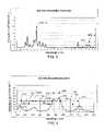
- FIGS. 3 and 4are absorption coefficient curves for a Nd:YAG gain medium.
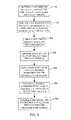
- FIG. 5is a flowchart illustrating a method in accordance with embodiments of the invention.
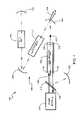
- FIG. 1illustrates a high-power laser system 100 in accordance with embodiments of the invention.
- the laser system 100includes a gain medium 102 , a pump module 104 and a laser resonator 106 .
- the gain medium 102is a doped crystalline host that is configured to absorb pump energy 108 generated by the pump module 104 having a wavelength that is within an operating wavelength range of the gain medium 102 .
- the gain medium 102is end-pumped by the pump energy 108 , which is transmitted through a beam splitter 110 that is transmissive at the wavelength of the pump energy 108 .
- the gain medium 102absorbs the pump energy 108 and responsively outputs laser light 112 .
- the gain medium 102is water cooled in exemplary embodiments, along the sides of the host.
- the gain medium 102includes an undoped end cap 114 bonded on a first end 116 of the gain medium 102 , and an undoped end cap 118 bonded on a second end 120 of the gain medium 102 .
- the end 120is coated so that it is reflective at the pump energy wavelength, while transmissive at a resonant mode of the system 100 . In this manner, the pump energy that is unabsorbed at the second end 120 is redirected back through the gain medium 102 to be absorbed.
- the laser pump module 104includes a plurality of laser diodes or bars 122 (hereinafter “laser diodes”), light combining optics 124 , a temperature control system 126 , a current or power source 128 , and a controller 130 , as shown in the simplified block diagram of FIG. 2 .
- the plurality of laser diodes 122operate to produce the pump energy 108 .
- the laser diodes 122are arranged in an array, such as a multiple bar stack of laser diodes 122 .
- the wavelength of the pump energy 108depends on the temperature of the laser diodes 122 and the current supplied to the laser diodes 122 .
- the controller 130controls the temperature control system 126 to maintain the laser diodes 122 at a desired operating temperature such that the pump energy 108 is within the operating wavelength range of the gain medium 102 .
- the controller 130controls the current source 128 to control the current to the laser diodes 122 and, thus, the power level and wavelength of the pump energy 108 .
- One embodiment of the controller 130includes one or more processors.
- the controller 130includes memory 132 that contains instructions executable by the one or more processors to perform various functions, such as, for example, controlling the current to the laser diodes 122 from the current or power source 128 to control the power level of the pump energy 108 , and controlling the temperature control system 126 to maintain the temperature of the laser diodes 122 at an operating temperature, at which the pump energy 108 at a given power level is within the operating wavelength range of the gain medium 102 .
- the light combining optics 124are configured to combine the light from the laser diodes 122 and output the combined light as the pump energy 108 .
- Embodiments of the light combining optics 124may comprise a collimation lens, a polarization multiplexer, a brightness doubler, beam shape optics and focusing lenses that focus the pump energy 108 near the first end of the gain medium 102 , and/or other optical components.
- the laser resonator 106is configured to generate a harmonic of the laser light 112 output from the gain medium 102 .
- the laser resonator 106includes a non-linear crystal (NLC) 150 , such as a lithium borate (LBO) crystal or a potassium titanyl phosphate crystal (KTP), for generating a second harmonic of the laser beam 112 emitted by the gain medium 102 .
- NLCnon-linear crystal
- LBOlithium borate
- KTPpotassium titanyl phosphate crystal
- the gain medium 102comprises a yttrium-aluminum-garnet (YAG) crystal rod with neodymium atoms dispersed in the YAG rod to form a Nd:YAG gain medium 102 , which outputs laser light 112 having a primary wavelength of 1064 nm.
- the laser resonator 106generates the second harmonic of the 1064 nm laser light 164 having a second harmonic wavelength of 532 nm.
- One advantage of the 532 nm wavelengthis that it is strongly absorbed by hemoglobin in blood and, therefore, is useful in medical procedures to cut, vaporize and coagulate vascular tissue.
- gain medium 102examples include yttrium-orthoaluminate crystal rod doped with thulium atoms (Tm:YALO) and neodymium doped yttrium-vanadate rod (Nd:YVO 4 ).
- the laser resonator 106includes a Q-switch 152 that operates to change the laser beam 112 into a train of short pulses with high peak power to increase the conversion efficiency of the second harmonic laser beam 164 .
- the laser resonator 106also includes reflecting mirrors 156 and 158 , and a folding mirror 160 .
- the mirrors 110 , 156 , 158 , 160 and mirror 162are highly reflective at the primary wavelength (e.g., 1064 nm).
- the folding mirror 160is also transmissive at the second harmonic output wavelength (e.g., 532 nm).
- the laser beam inside the resonator 106bounces back and forth between the mirrors 158 and 162 , reflects off the folding mirror 160 and propagates through the gain medium 102 and non-linear crystal 150 , and is discharged as output laser light 164 at the second harmonic wavelength.
- the Z-shaped resonant cavitycan be configured as discussed in U.S. Pat. No.
- the efficiency at which the gain medium 102 converts the pump energy 108depends on the length of the gain medium 102 and the absorption efficiency of the gain medium 102 at the wavelength of the pump energy 108 .
- the absorption efficiencyvaries with wavelength and is dependent on the dopant (e.g., neodymium atoms) and the doping concentration.
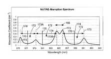
- FIG. 3shows the absorption coefficient (cm ⁇ 1 ) (y-axis) of the gain medium 102 (for approximately 0.3% neodymium concentration) versus pump energy wavelength (x-axis) (hereinafter “absorption coefficient curve”) over a practical range of wavelengths for a Nd:YAG gain medium.
- the absorption coefficientincludes peaks and valleys over the range of pump energy wavelengths.
- One conventional practiceis to utilize one of the narrow operating wavelength ranges 166 at one of the peaks of the absorption efficiency curve, such as at 808 nm or 885 nm, to maximize the conversion efficiency of the gain medium 102 .
- the narrow operating wavelength ranges at these peaksare approximately 1-2 nanometers.
- Such narrow operating wavelength bandsare intolerant to small wavelength shifts of the pump energy 108 , which can be caused by changes in the current to the laser diodes during a power level change of the pump energy 108 , or a change in the temperature of the laser diodes 122 .
- the operating wavelength range 166 of the Nd:YAG gain medium 102 around 885 nmis approximately 2 nm wide, as shown in FIG. 4 .
- the absorption efficiency of the gain medium 102decreases rapidly. This, in turn, results in lower absorption of the pump energy 108 by the gain medium 102 , which will adversely affect the output laser light 112 and the laser 164 .
- the stability of the wavelength of the pump energy 108is affected by feedback pump energy 168 , which is the portion of the unabsorbed pump energy 108 that is reflected off a reflector of the system and is fed back to the pump module 104 through the beam splitter 110 , as shown in FIG. 1 .
- the reflectormay include one or more of the mirrors 156 , 158 , 160 and 162 , or the end 120 of the gain medium.
- the feedback pump energy 168causes the wavelength of the output pump energy 108 to shift toward the wavelength of the feedback pump energy 168 .
- This wavelength shift of the pump energy 108decreases the amount of pump energy that is absorbed by the gain medium 102 and increases the magnitude of the feedback pump energy 168 .
- Embodiments of the inventionoperate to stabilize the wavelength of the pump energy 108 by setting the operating wavelength 170 of the pump energy 108 , which corresponds to the operating wavelength of the gain medium 102 , to a wavelength that is within a valley 172 of the absorption coefficient curve for the gain medium 102 rather than a peak 173 of the absorption coefficient curve, as illustrated in FIG. 4 .
- the operating wavelength 170is set to a wavelength at which the absorption coefficient of the gain medium is less than 40% of its value at either of the peaks 173 defining the valley, such as approximately 877 nm for the Nd:YAG gain medium 102 ( FIG. 4 ).
- the operating wavelength 170is set to a wavelength at which the absorption coefficient of the gain medium is less than 30% of its value at either of the peaks 173 defining the valley, such as approximately 881 nm and 889 nm for the Nd:YAG gain medium 102 . In one embodiment, the operating wavelength 170 is set to approximately the wavelength corresponding to the minimum absorption coefficient within one of the valleys 172 , or minimum absorption coefficient wavelength.
- the valley 172 of the absorption coefficient curve containing the operating wavelength 170has a peak-to-peak wavelength range 174 of at least approximately 3-4 nm.
- the operating wavelength 170 of the pump module 104is within a range of 879-883 nm. In another embodiment, the operating wavelength 170 is within a range of 875-879 nm. In yet another embodiment, the operating wavelength 170 is within a range of 887-890 nm.
- Shifts in the wavelength of the pump energy 108 from within the selected valley 172will generally result in increased absorption efficiency of the gain medium 102 due to the increase in the absorption coefficient. This causes a reduction in the magnitude of the feedback pump energy 168 and reduces the impact of the feedback pump energy 168 on the wavelength of the pump energy 108 . Even so, the majority of the feedback pump energy 168 will be at the minimum absorption coefficient wavelength for the gain medium 102 within the selected valley 172 . Thus, the feedback pump energy 168 will operate to stabilize the wavelength of the pump energy 108 .
- the feedback pump energy 168has a wavelength that approximately matches the operating wavelength 170 of the pump module.
- the gain medium 102is configured to have a pump energy to laser light conversion efficiency at the operating wavelength 170 of the pump module 104 . This is generally accomplished by selecting an appropriate doping level of the dopant (e.g., neodymium atoms) and the length of the crystal rod, in accordance with known techniques.
- the dopante.g., neodymium atoms
- the doping levelis relatively low to allow distribution of the thermal load along the optical axis of the gain medium 102 , thereby reducing the thermal stresses induced at the input end 116 ( FIG. 1 ) of the gain medium 102 .
- the doping concentration of the Nd:YAG gain medium 102is within a range of about 0.6% to 0.9%.
- the gain medium 102is approximately 100 millimeters long between the first end 116 and the second end 120 and has a diameter of approximately 4.5 millimeters.
- FIG. 5is a flowchart illustrating one embodiment of the method.
- a gain medium 102is provided having an absorption coefficient that varies with wavelength.
- the absorption coefficient curve for the gain medium 102comprises peaks 173 and valleys 172 , as illustrated in FIG. 4 .
- a pump module 104is operated to output pump energy 108 at an operating wavelength 170 within one of the valleys 172 .
- the absorption coefficient of the gain medium 102is approximately less than 40% of the absorption coefficient at an adjacent peak 173 of the absorption coefficient curve defining the valley 172 .
- the operating wavelength 170is selected to be approximately 881 nm
- the corresponding absorption coefficientis less than 40% of the absorption coefficient of the adjacent peaks 173 A and 173 B that define the valley 172 , as shown in FIG. 4 .
- the pump energy 108is directed through the gain medium 102 ( FIG. 1 ) and a portion of the pump energy 108 is absorbed by the gain medium at 186 .
- Laser light 112is emitted, at 188 , from the gain medium 102 responsive to the absorbed pump energy 108 .
- the non-absorbed pump energy or feedback pump energy 169is fed back to the pump module 104 , at 190 .
- the operating wavelength 170 of the pump energy 180is stabilized using the feedback pump energy 168 .
Landscapes
- Physics & Mathematics (AREA)
- Electromagnetism (AREA)
- Engineering & Computer Science (AREA)
- Plasma & Fusion (AREA)
- Optics & Photonics (AREA)
- Microelectronics & Electronic Packaging (AREA)
- Lasers (AREA)
Abstract
Description
Claims (20)
Priority Applications (2)
| Application Number | Priority Date | Filing Date | Title |
|---|---|---|---|
| US12/555,329US8897326B2 (en) | 2008-09-08 | 2009-09-08 | Pump energy wavelength stabilization |
| US14/532,234US9407058B2 (en) | 2008-09-08 | 2014-11-04 | Pump energy wavelength stabilization |
Applications Claiming Priority (2)
| Application Number | Priority Date | Filing Date | Title |
|---|---|---|---|
| US9508208P | 2008-09-08 | 2008-09-08 | |
| US12/555,329US8897326B2 (en) | 2008-09-08 | 2009-09-08 | Pump energy wavelength stabilization |
Related Child Applications (1)
| Application Number | Title | Priority Date | Filing Date |
|---|---|---|---|
| US14/532,234ContinuationUS9407058B2 (en) | 2008-09-08 | 2014-11-04 | Pump energy wavelength stabilization |
Publications (2)
| Publication Number | Publication Date |
|---|---|
| US20100061412A1 US20100061412A1 (en) | 2010-03-11 |
| US8897326B2true US8897326B2 (en) | 2014-11-25 |
Family
ID=41799254
Family Applications (2)
| Application Number | Title | Priority Date | Filing Date |
|---|---|---|---|
| US12/555,329Active2032-03-08US8897326B2 (en) | 2008-09-08 | 2009-09-08 | Pump energy wavelength stabilization |
| US14/532,234ActiveUS9407058B2 (en) | 2008-09-08 | 2014-11-04 | Pump energy wavelength stabilization |
Family Applications After (1)
| Application Number | Title | Priority Date | Filing Date |
|---|---|---|---|
| US14/532,234ActiveUS9407058B2 (en) | 2008-09-08 | 2014-11-04 | Pump energy wavelength stabilization |
Country Status (1)
| Country | Link |
|---|---|
| US (2) | US8897326B2 (en) |
Cited By (1)
| Publication number | Priority date | Publication date | Assignee | Title |
|---|---|---|---|---|
| US20150071317A1 (en)* | 2008-09-08 | 2015-03-12 | Ams Research Corporation | Pump energy wavelength stabilization |
Families Citing this family (3)
| Publication number | Priority date | Publication date | Assignee | Title |
|---|---|---|---|---|
| US8685011B2 (en) | 2010-12-15 | 2014-04-01 | Ams Research Corporation | Tunica ablation |
| US8672929B2 (en) | 2010-12-15 | 2014-03-18 | Ams Research Corporation | Laser probe tip |
| GB2527833B (en)* | 2014-07-03 | 2018-09-05 | Coherent Scotland Ltd | MOPA with high-gain solid-state amplifier |
Citations (34)
| Publication number | Priority date | Publication date | Assignee | Title |
|---|---|---|---|---|
| US4907235A (en) | 1988-04-01 | 1990-03-06 | Laserscope | Intra-cavity beam relay for optical harmonic generation |
| US4974230A (en) | 1988-08-23 | 1990-11-27 | The United States Of America As Represented By The Administrator Of The National Aeronautics And Space Administration | Tm,Ho:YLF laser end-pumped by a semiconductor diode laser array |
| JPH04137775A (en) | 1990-09-28 | 1992-05-12 | Nec Corp | Semiconductor laser excitation solid state laser |
| US5185758A (en) | 1989-11-28 | 1993-02-09 | Massachusetts Institute Of Technology | Multiple-laser pump optical system |
| US5205466A (en) | 1992-07-15 | 1993-04-27 | Chieh-Chang Tzeng | Manufacturing method of austenitic stainless steel self-tapping and self-drilling screw |
| US5337325A (en) | 1992-05-04 | 1994-08-09 | Photon Imaging Corp | Semiconductor, light-emitting devices |
| US5415655A (en)* | 1992-04-24 | 1995-05-16 | Surgical Laser Technologies, Inc. | Medical device including light energy emitting contact tip with means for raising temperature of the tip |
| US5530709A (en) | 1994-09-06 | 1996-06-25 | Sdl, Inc. | Double-clad upconversion fiber laser |
| US5638397A (en) | 1994-02-04 | 1997-06-10 | Spectra-Physics Lasers, Inc. | Confocal-to-concentric diode pumped laser |
| US5689522A (en) | 1995-10-02 | 1997-11-18 | The Regents Of The University Of California | High efficiency 2 micrometer laser utilizing wing-pumped Tm3+ and a laser diode array end-pumping architecture |
| EP0814550A2 (en) | 1996-06-17 | 1997-12-29 | Trw Inc. | Diode array for diode pumped solid state laser |
| US5809048A (en)* | 1994-11-14 | 1998-09-15 | Mitsui Petrochemical Industries, Ltd. | Wavelength stabilized light source |
| US5844149A (en) | 1996-09-19 | 1998-12-01 | Nkk Corporation | Method for analyzing solid specimen and apparatus therefor |
| US5859868A (en) | 1996-01-22 | 1999-01-12 | Nec Corporation | Solid-state laser device which is pumped by light output from laser diode |
| US5907570A (en) | 1997-10-22 | 1999-05-25 | Spectra-Physics, Inc. | Diode pumped laser using gain mediums with strong thermal focussing |
| US5974074A (en) | 1996-12-20 | 1999-10-26 | Oerlikon Contraves Ag | Laser system for optical free |
| US6026101A (en) | 1996-06-09 | 2000-02-15 | Ricoh Company, Ltd. | Solid-state laser apparatus |
| US6069907A (en) | 1996-09-10 | 2000-05-30 | Olive Tree Technology, Inc. | Laser diode pumped solid state laser and method using same |
| US6185236B1 (en) | 1999-02-02 | 2001-02-06 | University Of Central Florida | Self frequency double nd-doped: YCOB LASER |
| US6246706B1 (en) | 1999-05-27 | 2001-06-12 | Spectra Physics Lasers, Inc. | Laser writing method and apparatus |
| US6347101B1 (en) | 1998-04-16 | 2002-02-12 | 3D Systems, Inc. | Laser with absorption optimized pumping of a gain medium |
| US6366596B1 (en) | 2000-01-21 | 2002-04-02 | Photonics Industries International, Inc. | High power laser |
| US6407535B1 (en) | 2000-09-08 | 2002-06-18 | The Regents Of The University Of California | System for beaming power from earth to a high altitude platform |
| US6421573B1 (en) | 1999-05-27 | 2002-07-16 | Spectra Physics Lasers, Inc. | Quasi-continuous wave lithography apparatus and method |
| US6483858B1 (en) | 1999-11-23 | 2002-11-19 | Southeastern University Research Assn. | Injection mode-locking Ti-sapphire laser system |
| US6504858B2 (en) | 1998-11-24 | 2003-01-07 | Spectra Physics Lasers, Inc. | Lasers with low doped gain medium |
| US20030021324A1 (en)* | 2001-07-24 | 2003-01-30 | Gsi Lumonics, Inc. | Waveguide device with mode control and pump light confinement and method of using same |
| US6570902B2 (en) | 1998-11-12 | 2003-05-27 | Raytheon Company | Laser with gain medium configured to provide an integrated optical pump cavity |
| US6661568B2 (en) | 2000-08-29 | 2003-12-09 | Jenoptik Laser, Optik Systeme Gmbh | Diode-pumped laser amplifier |
| US6671305B2 (en) | 1996-11-29 | 2003-12-30 | Corporation For Laser Optics Research | Solid state laser |
| US6898231B2 (en) | 2002-11-21 | 2005-05-24 | Coherent, Inc. | Off-peak optical pumping of yttrium orthovanadate |
| US20070098024A1 (en) | 2005-10-28 | 2007-05-03 | Laserscope | High power, end pumped laser with off-peak pumping |
| EP1923971A1 (en) | 2006-11-17 | 2008-05-21 | Astrium Sas | Laser amplifier with several pumping device subassemblies |
| JP4137775B2 (en) | 2003-12-02 | 2008-08-20 | Tdk株式会社 | Suspension retention pallet |
Family Cites Families (5)
| Publication number | Priority date | Publication date | Assignee | Title |
|---|---|---|---|---|
| US5025446A (en) | 1988-04-01 | 1991-06-18 | Laserscope | Intra-cavity beam relay for optical harmonic generation |
| US5022041A (en)* | 1989-10-06 | 1991-06-04 | Spectra-Physics | Near resonant Nd3+, solid state laser system |
| US7200161B2 (en)* | 2001-01-22 | 2007-04-03 | The Boeing Company | Side-pumped solid-state disk laser for high-average power |
| US7046712B2 (en)* | 2003-05-02 | 2006-05-16 | Jds Uniphase Corporation | Laser resistant to internal ir-induced damage |
| US8897326B2 (en)* | 2008-09-08 | 2014-11-25 | Ams Research Corporation | Pump energy wavelength stabilization |
- 2009
- 2009-09-08USUS12/555,329patent/US8897326B2/enactiveActive
- 2014
- 2014-11-04USUS14/532,234patent/US9407058B2/enactiveActive
Patent Citations (35)
| Publication number | Priority date | Publication date | Assignee | Title |
|---|---|---|---|---|
| US4907235A (en) | 1988-04-01 | 1990-03-06 | Laserscope | Intra-cavity beam relay for optical harmonic generation |
| US4974230A (en) | 1988-08-23 | 1990-11-27 | The United States Of America As Represented By The Administrator Of The National Aeronautics And Space Administration | Tm,Ho:YLF laser end-pumped by a semiconductor diode laser array |
| US5185758A (en) | 1989-11-28 | 1993-02-09 | Massachusetts Institute Of Technology | Multiple-laser pump optical system |
| JPH04137775A (en) | 1990-09-28 | 1992-05-12 | Nec Corp | Semiconductor laser excitation solid state laser |
| US5415655A (en)* | 1992-04-24 | 1995-05-16 | Surgical Laser Technologies, Inc. | Medical device including light energy emitting contact tip with means for raising temperature of the tip |
| US5337325A (en) | 1992-05-04 | 1994-08-09 | Photon Imaging Corp | Semiconductor, light-emitting devices |
| US5205466A (en) | 1992-07-15 | 1993-04-27 | Chieh-Chang Tzeng | Manufacturing method of austenitic stainless steel self-tapping and self-drilling screw |
| US5638397A (en) | 1994-02-04 | 1997-06-10 | Spectra-Physics Lasers, Inc. | Confocal-to-concentric diode pumped laser |
| US5530709A (en) | 1994-09-06 | 1996-06-25 | Sdl, Inc. | Double-clad upconversion fiber laser |
| US5809048A (en)* | 1994-11-14 | 1998-09-15 | Mitsui Petrochemical Industries, Ltd. | Wavelength stabilized light source |
| US5689522A (en) | 1995-10-02 | 1997-11-18 | The Regents Of The University Of California | High efficiency 2 micrometer laser utilizing wing-pumped Tm3+ and a laser diode array end-pumping architecture |
| US5859868A (en) | 1996-01-22 | 1999-01-12 | Nec Corporation | Solid-state laser device which is pumped by light output from laser diode |
| US6026101A (en) | 1996-06-09 | 2000-02-15 | Ricoh Company, Ltd. | Solid-state laser apparatus |
| EP0814550A2 (en) | 1996-06-17 | 1997-12-29 | Trw Inc. | Diode array for diode pumped solid state laser |
| US6069907A (en) | 1996-09-10 | 2000-05-30 | Olive Tree Technology, Inc. | Laser diode pumped solid state laser and method using same |
| US5844149A (en) | 1996-09-19 | 1998-12-01 | Nkk Corporation | Method for analyzing solid specimen and apparatus therefor |
| US6671305B2 (en) | 1996-11-29 | 2003-12-30 | Corporation For Laser Optics Research | Solid state laser |
| US5974074A (en) | 1996-12-20 | 1999-10-26 | Oerlikon Contraves Ag | Laser system for optical free |
| US5907570A (en) | 1997-10-22 | 1999-05-25 | Spectra-Physics, Inc. | Diode pumped laser using gain mediums with strong thermal focussing |
| US6347101B1 (en) | 1998-04-16 | 2002-02-12 | 3D Systems, Inc. | Laser with absorption optimized pumping of a gain medium |
| US6570902B2 (en) | 1998-11-12 | 2003-05-27 | Raytheon Company | Laser with gain medium configured to provide an integrated optical pump cavity |
| US6504858B2 (en) | 1998-11-24 | 2003-01-07 | Spectra Physics Lasers, Inc. | Lasers with low doped gain medium |
| US6185236B1 (en) | 1999-02-02 | 2001-02-06 | University Of Central Florida | Self frequency double nd-doped: YCOB LASER |
| US6421573B1 (en) | 1999-05-27 | 2002-07-16 | Spectra Physics Lasers, Inc. | Quasi-continuous wave lithography apparatus and method |
| US6246706B1 (en) | 1999-05-27 | 2001-06-12 | Spectra Physics Lasers, Inc. | Laser writing method and apparatus |
| US6483858B1 (en) | 1999-11-23 | 2002-11-19 | Southeastern University Research Assn. | Injection mode-locking Ti-sapphire laser system |
| US6366596B1 (en) | 2000-01-21 | 2002-04-02 | Photonics Industries International, Inc. | High power laser |
| US6661568B2 (en) | 2000-08-29 | 2003-12-09 | Jenoptik Laser, Optik Systeme Gmbh | Diode-pumped laser amplifier |
| US6407535B1 (en) | 2000-09-08 | 2002-06-18 | The Regents Of The University Of California | System for beaming power from earth to a high altitude platform |
| US20030021324A1 (en)* | 2001-07-24 | 2003-01-30 | Gsi Lumonics, Inc. | Waveguide device with mode control and pump light confinement and method of using same |
| US6898231B2 (en) | 2002-11-21 | 2005-05-24 | Coherent, Inc. | Off-peak optical pumping of yttrium orthovanadate |
| JP4137775B2 (en) | 2003-12-02 | 2008-08-20 | Tdk株式会社 | Suspension retention pallet |
| US20070098024A1 (en) | 2005-10-28 | 2007-05-03 | Laserscope | High power, end pumped laser with off-peak pumping |
| US20080144690A1 (en) | 2005-10-28 | 2008-06-19 | Laserscope | High power, end pumped laser with off-peak pumping |
| EP1923971A1 (en) | 2006-11-17 | 2008-05-21 | Astrium Sas | Laser amplifier with several pumping device subassemblies |
Non-Patent Citations (22)
| Title |
|---|
| Bi, Yong et al., "Configuration to improve second-harmonic-generation conversion efficiency", Applied Optics, Feb. 10, 2004, vol. 43, No. 5, pp. 1174-1179. |
| Hardman, P.J., "Energy-Transfer Upconversion and Thermal Lensing in High-Power End-Pumped Nd:YLF Laser Crystals", IEEE Journal Quantum Electronics, Apr. 4, 1999, vol. 35. |
| Honea, Eric, C. et al., "115-W Tm:YAG Diode-Pumped Solid-State Laser", IEE Journal of Quantum Electronics, Sep. 1997, vol. 33, No. 9, pp. 1592-1600. |
| Honea, Eric, C. et al., "Analysis of an intracavity-doubled diode-pumped Q-switched Nd:YAG laser producing more that 100 W of power at 0.532 mum" Optical Letters, Aug. 1, 1998, vol. 23, No. 15, pp. 1203-1205. |
| Honea, Eric, C. et al., "Analysis of an intracavity-doubled diode-pumped Q-switched Nd:YAG laser producing more that 100 W of power at 0.532 μm" Optical Letters, Aug. 1, 1998, vol. 23, No. 15, pp. 1203-1205. |
| International Search Report and Written Opinion of PCT/US2009/056193, filed Sep. 8, 2009. |
| Kasamatsu, Tadashi et al., "Laser-diode-pumped Nd:YAG active-mirror laser" Applied Optics, Mar. 20, 1997, vol. 36, No. 9, pp. 1879-1881. |
| Lai, K.S. et al., "120-W continuous-wave diode-pumped Tm:YAG laser" Optics Letters, Nov. 1, 2000, vol. 25, No. 21, pp. 1591-1593. |
| Lin, Guo, et al., "Diode-end-pumped passively mode-locked ceramic Nd:YAG Laser with a semiconductor saturable mirror" Optics Express, May 30, 2005, vol. 13, No. 11, pp. 4085-4089. |
| Liu, Qiang, et al., "520-W continuous-wave diode corner-pumped composite Yb:YAG slab laser", Optics Letters, Apr. 1, 2005, vol. 30, No. 7, pp. 726-728. |
| Martel, G., et al., "Experimental and theoretical evidence of pump-saturation effects in low power end-pumped Nd:YVO4 microchip laser" Optics Communications, Sep. 28, 2000, vol. 185, pp. 419-430. |
| Mingxin, Qiu, et al., "Perfomance of a Nd:YVO4 microchip laser with continuous-wave pumping at wavelengths between 741 and 825 nm" Applied Optics, Apr. 20, 1993, vol. 32, No. 12, pp. 2085-2086. |
| Mingxin, Qiu, et al., "Performance of a Nd:YVO4 microchip laser with continuous-wave pumping at wavelengths between 741 and 825 nm" Applied Optics, Apr. 20, 1993, vol. 32, No. 12, pp. 2085-2086. |
| Paschotta, R., et al., "Diode-pumped passively mode-locked lasers with high average power" Appl. Phys. B., May 24, 2000, 70 [Suppl.], pp. S25-S31. |
| Pollnau, M., "Upconversion-induced heat generation and thermal lensing in Nd:YLF and Nd:YAG", Physical Review B, Dec. 15, 1998. vol. 58, No. 24, pp. 076-091. |
| Prosecution history of U.S. Appl. No. 11/261,010, filed Oct. 28, 2005. |
| Saint-Gobain Crystals "Nd:YAG Neodymium-Doped YAG Laser Crystals". |
| Schiehlen, Eckart, et al., "Diode-Pumped Semiconductor Disk Laser With Intracavity Frequency Doubling Using Lithium Triborate (LBO)" IEEE Photonics Technology Letters, Jun. 2002, vol. 14, No. 6, pp. 777-779. |
| Tusnekane, M., "High power operation of diode-end pumped Nd:YVO4 laser using composite rod with undoped end", Electronic Letters, Jan. 4, 2005, vol. 32, No. 1, pp. 40-42. |
| U.S. Appl. No. 61/094,462, filed Sep. 5, 2008. |
| U.S. Appl. No. 61/095,082, filed Sep. 8, 2008. |
| Xu, Degang, Wang, Yuye, Li, Haifeng, Yao, Jianquan, Tsang, Yuen H. "104 W high stability green laser generation by using diode laser pumped intracavity frequency-doubling Q-switched composite ceramic Nd: YAG laser" Apr. 2, 2007, vol. 15, No. 7, Optics Express 3991, (7 pages). |
Cited By (2)
| Publication number | Priority date | Publication date | Assignee | Title |
|---|---|---|---|---|
| US20150071317A1 (en)* | 2008-09-08 | 2015-03-12 | Ams Research Corporation | Pump energy wavelength stabilization |
| US9407058B2 (en)* | 2008-09-08 | 2016-08-02 | Boston Scientific Scimed, Inc. | Pump energy wavelength stabilization |
Also Published As
| Publication number | Publication date |
|---|---|
| US20100061412A1 (en) | 2010-03-11 |
| US20150071317A1 (en) | 2015-03-12 |
| US9407058B2 (en) | 2016-08-02 |
Similar Documents
| Publication | Publication Date | Title |
|---|---|---|
| EP2332222B1 (en) | Laser system having swithchable power modes | |
| US7995638B2 (en) | High power, end pumped laser with off-peak pumping | |
| US9407058B2 (en) | Pump energy wavelength stabilization | |
| US7616668B2 (en) | Fiber laser system using fiber having dysprosium | |
| US20100027571A1 (en) | Stabilized near-infrared laser | |
| JP2009253068A (en) | Laser oscillating device and laser processing device | |
| US5841801A (en) | Double wavelength laser | |
| US20090003402A1 (en) | Semiconductor-laser pumped Ti:sapphire laser | |
| JP2011521447A (en) | Intracavity second harmonic generation of a ruby laser pumped by an intracavity frequency doubled coupled cavity diode pumped ND laser | |
| US8194708B2 (en) | Laser | |
| JP2011134735A (en) | Pulsed fiber laser beam source and wavelength conversion laser beam source | |
| CN109904720B (en) | Injection frequency-locking 1342nm annular solid laser and control method | |
| Miao et al. | Low-threshold-intensity 3.8-W continuous-wave Ti: Sapphire oscillator directly pumped with green diodes | |
| CN209150479U (en) | Solid laser with one micron wave band | |
| US8315289B2 (en) | Optical apparatus and method | |
| US5381433A (en) | 1.94 μm laser apparatus, system and method using a thulium-doped yttrium-lithium-fluoride laser crystal pumped with a diode laser | |
| Peng et al. | Watt-level red and UV output from a CW diode array-pumped tunable alexandrite laser | |
| Ostermeyer et al. | 50 Watt average output power with 1.2* DL beam quality from a single rod Nd: YALO laser with phase-conjugating SBS mirror | |
| Badtke et al. | Yellow Solid-State Laser with 61% Slope Efficiency | |
| Bereczki et al. | Three-level Nd: YLF Raman laser directly pumped by a beam shaped diode bar | |
| US7088760B1 (en) | Solid-state laser apparatus including in resonator light-transmitting element having relatively small reflectance at desired wavelength | |
| JP2981671B2 (en) | Laser diode pumped solid state laser | |
| JP2008147687A (en) | Ophthalmic laser unit | |
| CN108736303A (en) | Solid-state lasers in the one-micron band | |
| JPH09312431A (en) | Laser diode stimulated solid-state laser oscillator |
Legal Events
| Date | Code | Title | Description |
|---|---|---|---|
| AS | Assignment | Owner name:AMS RESEARCH CORPORATION,MINNESOTA Free format text:ASSIGNMENT OF ASSIGNORS INTEREST;ASSIGNORS:REED, EDWARD D., JR.;NEMEYER, RAYMOND ADAM;SIGNING DATES FROM 20090911 TO 20090914;REEL/FRAME:023252/0117 Owner name:AMS RESEARCH CORPORATION, MINNESOTA Free format text:ASSIGNMENT OF ASSIGNORS INTEREST;ASSIGNORS:REED, EDWARD D., JR.;NEMEYER, RAYMOND ADAM;SIGNING DATES FROM 20090911 TO 20090914;REEL/FRAME:023252/0117 | |
| AS | Assignment | Owner name:MORGAN STANLEY SENIOR FUNDING, INC., AS ADMINISTRA Free format text:SECURITY AGREEMENT;ASSIGNOR:AMS RESEARCH CORPORATION;REEL/FRAME:026632/0535 Effective date:20110617 | |
| AS | Assignment | Owner name:AMS RESEARCH CORPORATION, MINNESOTA Free format text:RELEASE OF PATENT SECURITY INTEREST;ASSIGNOR:MORGAN STANLEY SENIOR FUNDING, INC., AS ADMINISTRATIVE AGENT;REEL/FRAME:032380/0053 Effective date:20140228 | |
| AS | Assignment | Owner name:DEUTSCHE BANK AG NEW YORK BRANCH, AS COLLATERAL AGENT, NEW YORK Free format text:GRANT OF SECURITY INTEREST IN PATENTS;ASSIGNORS:ENDO PHARMACEUTICALS SOLUTIONS, INC.;ENDO PHARMACEUTICALS, INC.;AMS RESEARCH CORPORATION;AND OTHERS;REEL/FRAME:032491/0440 Effective date:20140228 Owner name:DEUTSCHE BANK AG NEW YORK BRANCH, AS COLLATERAL AG Free format text:GRANT OF SECURITY INTEREST IN PATENTS;ASSIGNORS:ENDO PHARMACEUTICALS SOLUTIONS, INC.;ENDO PHARMACEUTICALS, INC.;AMS RESEARCH CORPORATION;AND OTHERS;REEL/FRAME:032491/0440 Effective date:20140228 | |
| STCF | Information on status: patent grant | Free format text:PATENTED CASE | |
| AS | Assignment | Owner name:AMS RESEARCH, LLC, MINNESOTA Free format text:RELEASE BY SECURED PARTY;ASSIGNOR:DEUTSCHE BANK AG NEW YORK BRANCH;REEL/FRAME:036285/0146 Effective date:20150803 Owner name:LASERSCOPE, CALIFORNIA Free format text:RELEASE BY SECURED PARTY;ASSIGNOR:DEUTSCHE BANK AG NEW YORK BRANCH;REEL/FRAME:036285/0146 Effective date:20150803 Owner name:AMERICAN MEDICAL SYSTEMS, LLC, MINNESOTA Free format text:RELEASE BY SECURED PARTY;ASSIGNOR:DEUTSCHE BANK AG NEW YORK BRANCH;REEL/FRAME:036285/0146 Effective date:20150803 | |
| CC | Certificate of correction | ||
| AS | Assignment | Owner name:BOSTON SCIENTIFIC SCIMED, INC., MINNESOTA Free format text:ASSIGNMENT OF ASSIGNORS INTEREST;ASSIGNOR:AMS RESEARCH, LLC;REEL/FRAME:037902/0162 Effective date:20151210 Owner name:BOSTON SCIENTIFIC SCIMED, INC., MINNESOTA Free format text:ASSIGNMENT OF ASSIGNORS INTEREST;ASSIGNOR:AMERICAN MEDICAL SYSTEMS, LLC;REEL/FRAME:037902/0200 Effective date:20151210 | |
| MAFP | Maintenance fee payment | Free format text:PAYMENT OF MAINTENANCE FEE, 4TH YEAR, LARGE ENTITY (ORIGINAL EVENT CODE: M1551) Year of fee payment:4 | |
| MAFP | Maintenance fee payment | Free format text:PAYMENT OF MAINTENANCE FEE, 8TH YEAR, LARGE ENTITY (ORIGINAL EVENT CODE: M1552); ENTITY STATUS OF PATENT OWNER: LARGE ENTITY Year of fee payment:8 |