US8896656B2 - Personal control apparatus and method for sharing information in a collaborative workspace - Google Patents
Personal control apparatus and method for sharing information in a collaborative workspaceDownload PDFInfo
- Publication number
- US8896656B2 US8896656B2US12/474,670US47467009AUS8896656B2US 8896656 B2US8896656 B2US 8896656B2US 47467009 AUS47467009 AUS 47467009AUS 8896656 B2US8896656 B2US 8896656B2
- Authority
- US
- United States
- Prior art keywords
- control interface
- selectable
- video source
- indicator
- indicate
- Prior art date
- Legal status (The legal status is an assumption and is not a legal conclusion. Google has not performed a legal analysis and makes no representation as to the accuracy of the status listed.)
- Active, expires
Links
Images


Classifications
- H—ELECTRICITY
- H04—ELECTRIC COMMUNICATION TECHNIQUE
- H04N—PICTORIAL COMMUNICATION, e.g. TELEVISION
- H04N7/00—Television systems
- H04N7/14—Systems for two-way working
- H04N7/15—Conference systems
- H—ELECTRICITY
- H04—ELECTRIC COMMUNICATION TECHNIQUE
- H04N—PICTORIAL COMMUNICATION, e.g. TELEVISION
- H04N7/00—Television systems
- H04N7/14—Systems for two-way working
- H04N7/141—Systems for two-way working between two video terminals, e.g. videophone
- H04N7/142—Constructional details of the terminal equipment, e.g. arrangements of the camera and the display
- A—HUMAN NECESSITIES
- A47—FURNITURE; DOMESTIC ARTICLES OR APPLIANCES; COFFEE MILLS; SPICE MILLS; SUCTION CLEANERS IN GENERAL
- A47B—TABLES; DESKS; OFFICE FURNITURE; CABINETS; DRAWERS; GENERAL DETAILS OF FURNITURE
- A47B13/00—Details of tables or desks
- A47B13/08—Table tops; Rims therefor
- A—HUMAN NECESSITIES
- A47—FURNITURE; DOMESTIC ARTICLES OR APPLIANCES; COFFEE MILLS; SPICE MILLS; SUCTION CLEANERS IN GENERAL
- A47B—TABLES; DESKS; OFFICE FURNITURE; CABINETS; DRAWERS; GENERAL DETAILS OF FURNITURE
- A47B21/00—Tables or desks for office equipment, e.g. typewriters, keyboards
- A—HUMAN NECESSITIES
- A47—FURNITURE; DOMESTIC ARTICLES OR APPLIANCES; COFFEE MILLS; SPICE MILLS; SUCTION CLEANERS IN GENERAL
- A47B—TABLES; DESKS; OFFICE FURNITURE; CABINETS; DRAWERS; GENERAL DETAILS OF FURNITURE
- A47B21/00—Tables or desks for office equipment, e.g. typewriters, keyboards
- A47B21/06—Tables or desks for office equipment, e.g. typewriters, keyboards characterised by means for holding, fastening or concealing cables
- A—HUMAN NECESSITIES
- A47—FURNITURE; DOMESTIC ARTICLES OR APPLIANCES; COFFEE MILLS; SPICE MILLS; SUCTION CLEANERS IN GENERAL
- A47B—TABLES; DESKS; OFFICE FURNITURE; CABINETS; DRAWERS; GENERAL DETAILS OF FURNITURE
- A47B37/00—Tables adapted for other particular purposes
- A—HUMAN NECESSITIES
- A47—FURNITURE; DOMESTIC ARTICLES OR APPLIANCES; COFFEE MILLS; SPICE MILLS; SUCTION CLEANERS IN GENERAL
- A47B—TABLES; DESKS; OFFICE FURNITURE; CABINETS; DRAWERS; GENERAL DETAILS OF FURNITURE
- A47B83/00—Combinations comprising two or more pieces of furniture of different kinds
- A47B83/001—Office desks or work-stations combined with other pieces of furniture, e.g. work space management systems
- G—PHYSICS
- G06—COMPUTING OR CALCULATING; COUNTING
- G06F—ELECTRIC DIGITAL DATA PROCESSING
- G06F1/00—Details not covered by groups G06F3/00 - G06F13/00 and G06F21/00
- G06F1/16—Constructional details or arrangements
- G06F1/1613—Constructional details or arrangements for portable computers
- G06F1/1632—External expansion units, e.g. docking stations
- G—PHYSICS
- G06—COMPUTING OR CALCULATING; COUNTING
- G06F—ELECTRIC DIGITAL DATA PROCESSING
- G06F1/00—Details not covered by groups G06F3/00 - G06F13/00 and G06F21/00
- G06F1/16—Constructional details or arrangements
- G06F1/1613—Constructional details or arrangements for portable computers
- G06F1/1633—Constructional details or arrangements of portable computers not specific to the type of enclosures covered by groups G06F1/1615 - G06F1/1626
- G06F1/1637—Details related to the display arrangement, including those related to the mounting of the display in the housing
- G06F1/1647—Details related to the display arrangement, including those related to the mounting of the display in the housing including at least an additional display
- G—PHYSICS
- G06—COMPUTING OR CALCULATING; COUNTING
- G06F—ELECTRIC DIGITAL DATA PROCESSING
- G06F3/00—Input arrangements for transferring data to be processed into a form capable of being handled by the computer; Output arrangements for transferring data from processing unit to output unit, e.g. interface arrangements
- G06F3/01—Input arrangements or combined input and output arrangements for interaction between user and computer
- G06F3/048—Interaction techniques based on graphical user interfaces [GUI]
- G06F3/0481—Interaction techniques based on graphical user interfaces [GUI] based on specific properties of the displayed interaction object or a metaphor-based environment, e.g. interaction with desktop elements like windows or icons, or assisted by a cursor's changing behaviour or appearance
- G—PHYSICS
- G06—COMPUTING OR CALCULATING; COUNTING
- G06F—ELECTRIC DIGITAL DATA PROCESSING
- G06F3/00—Input arrangements for transferring data to be processed into a form capable of being handled by the computer; Output arrangements for transferring data from processing unit to output unit, e.g. interface arrangements
- G06F3/14—Digital output to display device ; Cooperation and interconnection of the display device with other functional units
- G06F3/1423—Digital output to display device ; Cooperation and interconnection of the display device with other functional units controlling a plurality of local displays, e.g. CRT and flat panel display
- G06F3/1446—Digital output to display device ; Cooperation and interconnection of the display device with other functional units controlling a plurality of local displays, e.g. CRT and flat panel display display composed of modules, e.g. video walls
- G—PHYSICS
- G06—COMPUTING OR CALCULATING; COUNTING
- G06F—ELECTRIC DIGITAL DATA PROCESSING
- G06F3/00—Input arrangements for transferring data to be processed into a form capable of being handled by the computer; Output arrangements for transferring data from processing unit to output unit, e.g. interface arrangements
- G06F3/14—Digital output to display device ; Cooperation and interconnection of the display device with other functional units
- G06F3/147—Digital output to display device ; Cooperation and interconnection of the display device with other functional units using display panels
- H—ELECTRICITY
- H04—ELECTRIC COMMUNICATION TECHNIQUE
- H04N—PICTORIAL COMMUNICATION, e.g. TELEVISION
- H04N5/00—Details of television systems
- H04N5/222—Studio circuitry; Studio devices; Studio equipment
- H04N5/262—Studio circuits, e.g. for mixing, switching-over, change of character of image, other special effects ; Cameras specially adapted for the electronic generation of special effects
- H04N5/268—Signal distribution or switching
- H—ELECTRICITY
- H04—ELECTRIC COMMUNICATION TECHNIQUE
- H04N—PICTORIAL COMMUNICATION, e.g. TELEVISION
- H04N5/00—Details of television systems
- H04N5/64—Constructional details of receivers, e.g. cabinets or dust covers
- H—ELECTRICITY
- H04—ELECTRIC COMMUNICATION TECHNIQUE
- H04N—PICTORIAL COMMUNICATION, e.g. TELEVISION
- H04N5/00—Details of television systems
- H04N5/66—Transforming electric information into light information
- H—ELECTRICITY
- H04—ELECTRIC COMMUNICATION TECHNIQUE
- H04N—PICTORIAL COMMUNICATION, e.g. TELEVISION
- H04N7/00—Television systems
- H04N7/10—Adaptations for transmission by electrical cable
- H04N7/102—Circuits therefor, e.g. noise reducers, equalisers, amplifiers
- H04N7/104—Switchers or splitters
- H—ELECTRICITY
- H04—ELECTRIC COMMUNICATION TECHNIQUE
- H04N—PICTORIAL COMMUNICATION, e.g. TELEVISION
- H04N7/00—Television systems
- H04N7/14—Systems for two-way working
- H04N7/141—Systems for two-way working between two video terminals, e.g. videophone
- H04N7/147—Communication arrangements, e.g. identifying the communication as a video-communication, intermediate storage of the signals
- H—ELECTRICITY
- H04—ELECTRIC COMMUNICATION TECHNIQUE
- H04N—PICTORIAL COMMUNICATION, e.g. TELEVISION
- H04N7/00—Television systems
- H04N7/18—Closed-circuit television [CCTV] systems, i.e. systems in which the video signal is not broadcast
- H04N7/183—Closed-circuit television [CCTV] systems, i.e. systems in which the video signal is not broadcast for receiving images from a single remote source
- A—HUMAN NECESSITIES
- A47—FURNITURE; DOMESTIC ARTICLES OR APPLIANCES; COFFEE MILLS; SPICE MILLS; SUCTION CLEANERS IN GENERAL
- A47B—TABLES; DESKS; OFFICE FURNITURE; CABINETS; DRAWERS; GENERAL DETAILS OF FURNITURE
- A47B21/00—Tables or desks for office equipment, e.g. typewriters, keyboards
- A47B21/06—Tables or desks for office equipment, e.g. typewriters, keyboards characterised by means for holding, fastening or concealing cables
- A47B2021/066—Tables or desks for office equipment, e.g. typewriters, keyboards characterised by means for holding, fastening or concealing cables with power or communication connection interface
- A—HUMAN NECESSITIES
- A47—FURNITURE; DOMESTIC ARTICLES OR APPLIANCES; COFFEE MILLS; SPICE MILLS; SUCTION CLEANERS IN GENERAL
- A47B—TABLES; DESKS; OFFICE FURNITURE; CABINETS; DRAWERS; GENERAL DETAILS OF FURNITURE
- A47B83/00—Combinations comprising two or more pieces of furniture of different kinds
- A47B83/001—Office desks or work-stations combined with other pieces of furniture, e.g. work space management systems
- A47B2083/003—Table combination having a central power access component
- A—HUMAN NECESSITIES
- A47—FURNITURE; DOMESTIC ARTICLES OR APPLIANCES; COFFEE MILLS; SPICE MILLS; SUCTION CLEANERS IN GENERAL
- A47B—TABLES; DESKS; OFFICE FURNITURE; CABINETS; DRAWERS; GENERAL DETAILS OF FURNITURE
- A47B83/00—Combinations comprising two or more pieces of furniture of different kinds
- A47B83/001—Office desks or work-stations combined with other pieces of furniture, e.g. work space management systems
- A47B2083/005—Office wall with desktop function
- A47B2083/006—Office wall with desktop function having an incorporated display screen
Definitions
- the present inventionrelates to the presentation of audiovisual information via one or more large format common displays in a collaborative workspace and more specifically to a fast and intuitive controller allowing a meeting participant with a laptop computer to quickly and easily control the presentation of laptop information on common displays.
- Small group conference tables usable as collaborative workspaceshave been designed with one or more large video displays such as a LCD flat-panel monitor or a wall suitable for having images projected thereon, connected to or adjacent the conference table.
- the basic intent behind such workspace designsis to provide information at or near a table edge for attendees to refer to during discussions and presentations.
- the video displayis connected to and driven by a dedicated computer.
- Another way of enabling several attendees to share audiovisual information from their own laptop computers via a common large video display screenis to provide separate audio/video cables for each presenter and connect each of the laptops to an audiovisual switching device that enables the attendees to take control of the common display screen via selection of a button associated with each of the audio/video cables.
- a simple control interfacemay be provided where the interface provides feedback to configuration users indicating which of several different conference attendees is presenting information via one or more common display screens or presentation spaces.
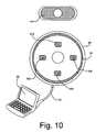
- a separate control interfaceis provided for each of a plurality of attendees where each interface includes control buttons or the like and indicators that can indicate visually distinguished states. For instance, when a laptop or other video/audio source is linked to one of the control interfaces, the interface may visually indicate that the laptop is in a state wherein the laptop may be used to present information via one or more common displays but that the laptop is not currently presenting. When a user selects one of the buttons on the interface to present information on the common display, the indicator may change appearance to visually indicate to attendees that the laptop linked to the interface is presenting.
- each control interfaceis configured to include a separate selectable buttons for each common display where, when a button is selected so that a source associated with the interface is to drive an associated display, the appearance of the button or an indicator associated therewith is modified to indicate to the user which of the common displays is currently being driven.
- the indicatorsinclude illumination devices wherein different illumination colors indicate different states or conditions.
- At least some inventive embodimentsinclude a method of selecting information from a video source to be displayed on at least a first common display screen in a collaborative workspace having a switching device, the method comprising the steps of providing a selectable control interface that includes at least one indicator that can indicate at least first and second different states, associating a video source with the switching device so that video information from the video source is presented to the switching device, when the video source is associated with the switching device, causing the at least one indicator to indicate a first state and, when the selectable control interface is selected, causing the at least one indicator to indicate the second state and providing the video information from the video source to the common display screen via the switching device.
- the step of providing a selectable control interfaceincludes providing a mechanical interface that includes at least one selectable button.
- the mechanical interfaceincludes a first cable linkable to the video source and a second cable which links to the switching device and wherein the step of associating a video source with the switching device includes linking the first cable to the video source.
- the indicatorincludes at least a first illumination device wherein the steps of causing the at least one indicator to indicate the first and second states includes causing the illumination device to light up first and second different colors, respectively.
- control interfaceforms a substantially flat upper surface and wherein the at least a first illumination device transmits light around a periphery of the flat upper surface.
- the methodfurther includes the step of, while the video information from the video source is provided to the shared display screen via the switching device, when the selectable control interface is selected a second time, causing the at least one indicator to indicate the first state and blocking the video information from the video source to the shared display screen via the switching device.
- the methodis for use with a system that includes a plurality of common display screens wherein the selectable control interface includes a separate selectable control for each of the plurality of display screens and wherein the at least one indicator includes a separate illumination device for each of the separate selectable controls, the step of causing the at least one indicator to indicate the first state including causing each illumination device associated with a common display screen to generate light of a first color indicating the first state and wherein, when any one of the control interfaces is selected, the method further includes the steps of causing the illumination device associated with the selected control to indicate the second state and providing the video information from the video source to the common display screen associated with the selected control.
- the methodfurther includes the steps of providing a second selectable control interface that includes at least one indicator that can indicate at least first and second different states, associating a second video source with the switching device so that video information from the second video source is presented to the switching device, when the second video source is associated with the switching device, causing the at least one indicator on the second control interface to indicate the first state and when the second selectable control interface is selected, causing the at least one indicator on the second control interface to indicate the second state and providing the video information from the second video source to the common display screen via the switching device irrespective of which source was providing video information to the common display screen prior to selection of the second selectable control interface device.
- the video sourceis a computer including a display screen and wherein the control interface appears on the computer display screen for selection.
- communication between the computer and the switching deviceis wireless.
- Other embodimentsinclude a method of selecting information from a video source to be displayed on a subset of M common display screens in a collaborative workspace having a switching device, the method comprising the steps of providing a control interface that includes N selectable controls wherein N is at least as great as M and wherein each control is associated with a separate indicator and each indicator may assume at least first and second visually distinguishable states, associating a video source with the switching device so that video information from the video source is presented to the switching device and when the video source is associated with the switching device, causing a separate indicator for each of the M common display screens to assume the second visual state while the other N-M indicators remain in the first visual state.
- each controlincludes a separate illumination device which may be illuminated to indicate at least one of the first and second states.
- each controlindicates the second state by exciting an associated illumination device and indicates the first state by cutting off power to the illumination device.
- each of the indicatorsmay assume a third visually distinguishable state, the method further including the steps of, when any of the selectable controls is selected, causing the indicator associated with the selected control to indicate the third state and providing the video information from the video source to the common display screen via the switching device.
- control interfaceis provided via a representation on a computer display screen.
- step of providing a control interfaceincludes providing a mechanical interface that includes a cable and wherein the step of associating a video source with the switching device includes linking the video source to the mechanical interface via a cable.
- Still other embodimentsinclude an apparatus for selecting information from a video source to be displayed on at least a first common display screen in a collaborative workspace having a switching device, the apparatus comprising a control interface that includes at least a first indicator that can visually indicate at least first, second and third visually distinguished states wherein the control interface indicates the first state when a video source is disassociated with the switching device, the second state when the video source is associated with the switching device and video information from the video source is not presented via the common display and the third state when the video source is associated with the switching device and video information from the video source is presented via the common display.
- the at least a first indicatorincludes an illumination device and wherein the first state is indicated by cutting power to the illumination device, the second state is indicated via illumination of a first color and the second state is indicated via illumination of a second color.
- the control interfaceincludes at least a first selectable control which, when selected, causes the video information from the video source to be presented via the common display and causes the indicator to change from the first state to the second state.
- inventionsinclude an apparatus for selecting information from a video source to be displayed on a subset of M common display screens in a collaborative workspace having a switching device, the apparatus comprising a control interface that includes N selectable controls wherein N is at least as great as M and wherein each control is associated with a separate indicator and each indicator may assume at least first and second visually distinguishable states, wherein, when a video source is not associated with the switching device, each indicator indicates the first state and, when a video source is associated with the switching device, a separate indicator for each of the M common display screens assumes the second state while the other N-M indicators remain in the first state.
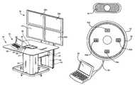
- FIG. 1is a perspective view of a collaborative conference table configuration having four display screens in accordance with at least some aspects of the present invention
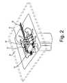
- FIG. 2is a view of a portion of the configuration shown in FIG. 1 , albeit where a switcher and other components and cables that are typically hidden under the top surface of FIG. 1 are shown in perspective views;
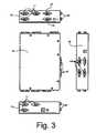
- FIG. 3includes a top plan view, end views and a side view of the switcher shown in FIG. 2 ;
- FIG. 4is an enlarged perspective view showing one of the puck control assemblies that comprises a portion of the configurations shown in FIG. 1 ;
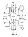
- FIG. 5is a schematic illustrating components of an exemplary control interface/puck
- FIG. 6is a schematic illustrating the puck control assembly of FIG. 4 and a power on button in the first state after the power on button has been selected to cause the system to begin operation;
- FIG. 7is a schematic illustrating an exemplary screen shot corresponding to a portion of an instructional video that may be presented via one or more of the displays shown in FIG. 1 after the power on button is selected;
- FIG. 8is similar to FIG. 7 , albeit illustrating a different portion of the instructional video
- FIG. 9is similar to FIG. 7 , albeit illustrating yet a different portion of the instructional video
- FIG. 10is similar to FIG. 6 , albeit illustrating the state of the puck when a laptop is initially connected thereto;
- FIG. 11is similar to FIG. 10 , albeit illustrating the state of the puck after a selection button corresponding to one of the display screens of FIG. 1 has been selected;
- FIG. 12is similar to FIG. 11 , albeit illustrating the puck condition after three buttons corresponding to three of the display screens shown in FIG. 1 have been selected;
- FIG. 13is similar to FIG. 1 , albeit illustrating another configuration embodiment as consistent with at least some aspects of the present invention
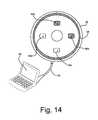
- FIG. 14is similar to FIG. 10 , albeit illustrating the puck condition for the system of FIG. 12 where the system only includes two displays;
- FIG. 15is similar to FIG. 1 , albeit illustrating a system that includes a wireless access device so that laptops and other video/audio sources can link provide data to the displays wirelessly;
- FIG. 16shows a puck “widget” that may be presented via a laptop display screen
- FIG. 17shows a puck “widget” provided on a touch sensitive palm type computing device
- FIG. 18is similar to FIG. 16 , albeit showing a different appearing virtual control interface.
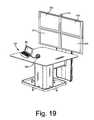
- FIG. 19is similar to FIG. 15 , albeit where a mechanical interface is included for use with a source.
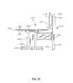
- FIG. 20is a perspective view of a conferencing table assembly that is consistent with at least some aspects of the present invention:
- FIG. 21is a side of plan view of the conferencing table assembly of FIG. 20 ;
- FIG. 22is a front plan view of the conferencing table assembly of FIG. 20 ;
- FIG. 23is a top plan view of the conferencing table assembly of FIG. 20 ;
- FIG. 24is a partially exploded perspective view of the conference table assembly of FIG. 20 ;
- FIG. 25is a partially exploded side plan view of the conferencing table of FIG. 20 ;
- FIG. 26is an exploded view of the retractor assembly shown in FIG. 24 ;
- FIG. 27is a partially exploded view of the retractor assembly of FIG. 26 ;
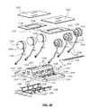
- FIG. 28is a partially exploded view of the deck assembly of FIG. 24 ;
- FIG. 29is a top plan view of the cable tie bracket shown in FIG. 28 ;
- FIG. 30is a top plan view of the deck member of FIG. 28 ;
- FIG. 31is a perspective view of an exemplary handset and cable assembly including video and audio cables and jacks;
- FIG. 32is a perspective view of the deck assembly shown in FIG. 28 ;
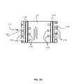
- FIG. 33is a partial cross sectional view showing the wire management assembly installed in a leg cavity with a single handset in a stowed position;
- FIG. 34is similar to FIG. 33 , albeit showing the single handset pulled out of a cavity;
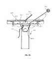
- FIG. 35is similar to FIG. 33 , albeit showing the handset in a use position with a cavity door member in a closed position;
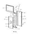
- FIG. 36is an exploded view of the totem/display assembly shown in FIG. 20 ;
- FIG. 37is an exploded view of the bridge assembly of FIG. 20 ;
- FIG. 38is a perspective view of a two display conferencing table
- FIG. 39is a cross sectional view of a handset that includes LEDs for signaling different conditions
- FIG. 40is a perspective view of yet another table assembly that is consistent with at least some aspects of the present invention.
- FIG. 41is a front plan view of the assembly shown in FIG. 40 ;
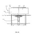
- FIG. 42is similar to FIG. 41 , albeit showing the assembly with various housing components removed;
- FIG. 43is a side plan view of the assembly shown in FIG. 40 ;
- FIG. 44is a perspective showing a wire management assembly that forms part of the assembly shown in FIG. 40 ;
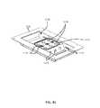
- FIG. 45is a perspective view showing a sub-set of the housing components shown in FIG. 44 ;
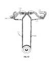
- FIG. 46is a perspective view showing handsets, associated cables and pulleys used to form part of the assembly shown in FIG. 44 ;
- FIG. 47is a front perspective view of the sub-assembly of FIG. 46 , albeit without data jacks;
- FIG. 48is a perspective view of a wire management system including a single on/off button.
- Workspace configuration 10includes a display system 12 and a conference table assembly 14 .
- Various mechanical aspects of configuration 10are described in co-pending U.S. patent application Ser. No. 12/250,192 that was filed on Oct. 13, 2008 and is titled “Conference Table Assembly” and which is incorporated herein by reference.
- U.S. patent application Ser. No. 12/250,192has issued as U.S. Pat. No. 8,074,581 and discloses the following:
- the present inventionrelates to conferencing furniture and more specifically to conferencing tables for use with one or more display screens where multiple conference attendees can provide content for driving images presented via the display screen(s).
- Small group (e.g., 4 to 8 attendees) conference tableshave been designed that include one or more large display screens adjacent a table top edge or wall mounted or ceiling hung display or projection screens offset a distance from a table top edge.
- the ideahas been to provide information at or near a table edge for attendees to refer to during discussions and presentations.
- attendeesuse laptops or other digital information sources to drive the information presented via the display.
- power and data receptaclesare often provided within conference tables (e.g., below grommet doors or covers that are flush with the top surface of a table top).
- a laptop usertypically uses her own power and data cables to link to the receptacles.
- conference roomsare often equipped with audio and video cables to link a laptop to a display or to a projector for controlling presented information.
- One way to allow several attendees to present information via a displayis to sequentially have each presenter link to the display or projector via the audio and video cables.
- transitions between presenterstake time and are extremely disruptive.
- One other way to allow several attendees to presentis to provide separate audio and video cables for each presenter and a switcher device that enables each of the attendees to take control of the display screen via selection of a button associated with the presenters audio and video cables.
- One such switcher/cable/button assembly of this typeis the DTS-TS8 switcher assembly by Elecom that provides eight separate audio/video cable assemblies and eight associated buttons along with a switcher that has eight input ports and one screen output port.
- the source selection buttons and associated audio and video cablesare needed to interface with the switcher, these cables are typically kept with the switcher.
- the audio/video/control cablese.g., eight
- the cablesoften remain strewn across a table top and the overall scene is unsightly.
- Some conference table power and data/communication cable management solutionshave been developed.
- cable systemshave been developed that include spring loaded cable dispensers for dispensing network communication types cables (e.g., CAT-5 cables) for use at a conference table.
- a dispenser housingis provided that mounts to the top surface of a table top or the like and a plurality (e.g., 8) of cable dispensers are mounted within the housing.
- One end of each cablecan be pulled against the force or the spring out of each dispenser and plugged into a laptop.
- the cablecan be retracted via the spring force back into the dispenser and housing. While this solution works well for relatively thin communication type cables, this solution has several shortcomings.
- a simple spring loaded dispensermay need to be relatively large and the spring force would have to be relatively high to accomplish the retracting activity and therefore the overall size of the dispensing system would have to be increased appreciably.
- a spring loaded table top mounted dispensing systemis not practical for many applications and, at best, solves the data cable management problem in a relatively unsightly manner.
- conference tablesare known that include power and data receptacles mounted below a table top member where the top member forms openings for passing cables for receptacle hookup and where cable receiving and retaining cavities have been formed adjacent the receptacles for receiving and storing excess power and data cable lengths.
- the top memberforms openings for passing cables for receptacle hookup and where cable receiving and retaining cavities have been formed adjacent the receptacles for receiving and storing excess power and data cable lengths.
- a storage spacecan be provided below a table top opening for receiving control cables when the cables are not in use or to receive portions of control cables that are not in use.
- a weight of some typecan be linked to each of the control cables below the top surface where the weight tends to pull the cable into the space below the table top to aid a cable user in moving the cable back into the space when not in use.
- the weightcan substantially automatically take up any slack in a control cable between a handset that includes a control button and the table top opening so that excess cable is removed from the table top surface.
- the handsetcan be constructed to be relatively heavy so that the handset can be placed on the table top surface and remain in its disposed position despite the weight tending to pull the handset and cable back into the storage space.
- the handsetmay include rubber or tacky plastic strips or foot members on an undersurface to help maintain the position of the handset after placement on a work surface or the like.
- the handsetmay include rubber strips or the like on a side or circumferential surface to help retain the handset in a receiving cavity during storage.
- the handsetmay, in some cases, include audio and/or video jacks that can be linked to a laptop computer or the like.
- the handset weightserves the additional purpose of reducing force applied to laptop audio and video jacks.
- a deck membermay be provided in the space below the table top member and on which the handsets can be placed and supported when not in use and door members may be provided to substantially cover (e.g., leave a slot open along one or more edges for cables to pass through) the opening when desired.
- At least some at least some embodiments of the inventioninclude a conferencing assembly for use with at least one computer, the assembly comprising a table top member having top and bottom surfaces and forming a table top opening, a leg support structure supporting the top member is a substantially horizontal orientation, a display screen associated with the top member and supported adjacent the top surface, a switcher for controlling input to the display screen, a plurality of handsets, each hand set including a selector button usable to send a signal to the switcher thereby causing the switcher to link a computer associated with the selector button to the display, a plurality of handset cables, each handset cable having first and second ends linked to the switcher and an associated selector button, respectively, for passing signals from the selector buttons to the switcher, a take up assembly including a separate weight for each of the handset cables, the take up assembly disposed below the top member and aligned with the table top opening, each handset cable linked to an associated weight, each weight applying a force tending to pull the second end of the associated handset
- each weightincludes a pulley wheel, each handset cable passing around an associated pulley wheel.
- each weightfurther includes first and second plates mounted on opposite sides of the pulley wheel. In at least some cases the plates are mounted to the pulley wheel axis via a pin.
- the assemblyfurther includes a guide structure, the guide structure forming a separate substantially vertical channel for each of the pulley wheels, each pulley wheel moving up and down within a channel as the second end of an associated cable is pulled away from and allowed to move toward the opening, respectively.
- the assemblyincludes at least four separate handsets.
- the take up assemblyfurther includes a deck member having a top deck surface below the top surface of the table top member, the deck member forming a separate opening for each of the handsets, each cable passing through a separate one of the openings formed by the deck member, the handsets received on the deck surface of the deck member thereby limiting downward movement through the opening formed by the deck member.
- the deck surfaceforms a recess proximate each of the openings formed by the deck member, each recess formed to receive an associated one of the handsets.
- the deck surfaceis substantially parallel to the top surface of the table top member.
- the assemblyfurther includes at least one utility wall member extending upward from the deck surface below the table top member and at least one of a power and a data receptacle mounted in the wall member for access through the table top opening.
- the assemblyfurther includes a utility island extending upward from the deck surface, the utility wall forming a circumferential wall about the island, the island further including a top mounting surface that is substantially parallel to the top surface of the table top member.
- the islandincludes at least first, second, third and fourth receptacles, the first and second receptacles facing in substantially opposite directions and the third and fourth receptacles facing in substantially opposite directions.
- the assemblyfurther includes first and second door members hingedly mounted to the mounting surface for movement between open and closed positions, each door member including a top door surface, when the door members are in the closed positions, the door members substantially closing the table top opening and the door surfaces substantially flush with the top surface of the table top member.
- an opening edgedefines the shape of the table top opening, the door members forming a gap with the opening edge when in the closed positions.
- each handset cablefurther includes a video cable and each handset further includes a video jack proximate the button for linking to an associated computer.
- each handset cablefurther includes an audio cable and each handset further includes an audio jack proximate the button for linking to an associated computer. In at least some cases each handset weighs at least one pound.
- Some embodimentsinclude a conferencing assembly for use with at least one computer, the assembly comprising a table top member having top and bottom surfaces and forming a table top opening, a leg support structure supporting the top member is a substantially horizontal orientation, a display screen associated with the top member and supported adjacent the top surface, a switcher for controlling input to the display screen, a plurality of handsets, each hand set including a selector button usable to send a signal to the switcher thereby causing the switcher to link a computer associated with the selector button to the display, a plurality of handset cables, each handset cable having first and second ends linked to the switcher and an associated selector button, respectively, for passing signals from the selector buttons to the switcher, a deck member having a top deck surface below the top surface of the table top member and aligned with the table top opening, the deck member forming a separate opening for each of the handsets, each handset cable passing through a separate one of the openings formed by the deck member, the handsets received on the deck surface of the deck member
- the leg support structureforma a leg cavity, the deck member and take up assembly disposed within the leg cavity.
- the switcheris also disposed within the leg cavity.
- Some embodimentsfurther include a totem assembly and a bridge member, the totem assembly having top and bottom ends and a mounting surface, the totem disposed adjacent the top member with the mounting surface above the top surface of the table top member, the bridge member having first and second ends secured to the leg support structure and the totem assembly, respectively, the display screen mounted to the mounting surface adjacent the top surface of the table top member.
- a conferencing assemblyfor use with at least one computer, the assembly comprising a table top member having top and bottom surfaces and forming a table top opening, a leg support structure supporting the top member is a substantially horizontal orientation, a display screen associated with the top member and supported adjacent the top surface, a switcher for controlling input to the display screen, a plurality of handsets, each hand set including a selector button usable to send a signal to the switcher thereby causing the switcher to link a computer associated with the selector button to the display, a plurality of handset cables, each handset cable having first and second ends linked to the switcher and an associated selector button, respectively, for passing signals from the selector buttons to the switcher and a deck member having a top deck surface below the top surface of the table top member and aligned with the table top opening, the deck member forming a separate opening for each of the handsets, each handset cable passing through a separate one of the openings formed by the deck member, the handsets received on the deck surface of the deck member thereby
- Some casesfurther include a take up assembly including a separate weight for each of the handset cables, the take up assembly disposed below the deck member, each handset cable linked to an associated weight, each weight applying a force tending to pull the second end of the associated handset cable toward the deck top.
- Table assembly 1012includes a leg support structure 1018 , a table top member 1020 and wire management assembly 1024 .
- leg support structure 1018includes vertical leg members 1076 , horizontal foot members 1080 , a foot rail 1022 , horizontal shoulder members 1077 and a top plate 1079 .
- four vertical leg members 1076are provided (only two illustrated) and the leg members are spaced apart to form a rectilinear leg cavity 1082 .
- Four foot members 1080extend from the vertical leg members 1076 or other leg structural components (e.g., horizontal members that extend between bottom ends of the vertical leg members 1076 ) in four opposite directions that provide stability to the leg members 1076 and other assembly components thereabove.
- Foot rail 1022is mounted to the top ends of vertical standoffs (not labeled) that extend up from distal ends of the foot members 1080 and, in the illustrated embodiment, forms a generally square shaped foot rest that circumscribes and is spaced apart from the vertical leg members 1076 .
- the top plate 1079is a rigid rectilinear member that forms a square plate opening 1081 (see FIG. 33 specifically). Top plate 1079 is mounted via welding or mechanical fasteners to the top ends of vertical leg member 1076 opposite foot members 1080 with the plate opening 1081 aligned with leg cavity 1082 there below. Although not illustrated or separately labeled, top plate 1079 forms a plurality of screw holes for passing screws used to mount other assembly components thereto. Screws are used to secure shoulder members 1077 to a top surface 1085 of top plate 1079 . Once shoulder members 1077 are secured to top plate 1079 , internal surfaces 1083 of shoulder members 1077 and the top surface 1085 of top plate 1079 form a separate well or cavity 1069 (see FIG. 33 ) that resides generally above leg cavity 1082 .
- leg housing member 1030is a three-sided leg structure that can be slid over and mechanically fasten to the vertical leg members 1076 to enclose the leg channel 1082 .
- table top member 1020is a rectilinear, planar and rigid member having top and bottom surfaces 1021 and 1023 , respectively. Referring also to FIG. 33 , top member 1020 forms a central substantially rectilinear opening 1027 .
- wire management assembly 1024includes first and second door or cover members 1025 and 1026 , respectively, a deck assembly 1045 and a retractor assembly 1052 .
- retractor assembly 1052includes a first slotted wall member 1054 , a second slotted wall member 1056 , a first end wall member 1058 , a second end wall member 1060 , a first bottom plate or bracket 1062 , a second bottom plate or bracket 1064 , seven separate divider members collectively identified by numeral 1066 , six separate pulley/weight assembly collectively identified by numeral 1068 , a first sloped mounting bracket 1070 , a second sloped mounting bracket 1072 and a plurality of screws for securing the retractor assembly components together, at least a subset of the screws collectively identified by numeral 1100 .
- slotted wall member 1056is generally a rigid rectilinear member including an external surface (not labeled) and an oppositely facing internal surface 1103 as well as top and bottom ends 1104 and 1106 , respectively, and first and second lateral edges 1108 and 1110 , respectively. As the label implies, member 1056 forms a plurality of slots collectively identified by numeral 1102 in internal surface 1103 .
- Each slot 1102is a straight slot that extends from the top end 1104 to the bottom end 1106 of member 1056 and all of the slots 1102 are parallel to a length dimension of member 1056 .
- member 1056forms threaded openings along each of the top, bottom, first lateral and second lateral edges for receiving shafts of screws to facilitate fastening of other retractor assembly components.
- each of the first and second end wall members 1058 and 1060is similarly constructed and operates in a similar fashion and therefore, only end wall 1058 will be described in any detail.
- Wall member 1058is a flat, rigid and rectilinear member that forms mounting openings (not labeled) along first and second lateral edges. The mounting openings formed by member 1058 align with the threaded shaft receiving openings formed in first lateral edge 1108 of member 1056 when wall member 1058 is placed adjacent edge 1108 .
- first bottom plate or bracket 1062is an elongated flat and rigid bracket that has a length dimension substantially equal to a width dimension of slotted wall member 1056 between the lateral edges 1108 and 1110 of member 1056 and forms openings for passing screws for attaching member 1064 to bottom edge 1106 of member 1056 .
- second bracket 1062is a rectilinear rigid bracket having a length dimension equal to a width dimension of first slotted wall member 1054 .
- Divider members 1066are rigid rectilinear members that each have thickness dimension substantially equal to a width dimension of one of the slots 1102 formed by member 1056 so that a lateral edge of each divider member 1066 is receivable within one of the slots 1102 .
- Divider members 1066have length dimensions substantially equal to a length dimension of slotted wall member 1056 and have a width dimension such that, when retractor assembly 1052 is assembled, each divider member 1066 traverses the distance between slotted wall member 1054 and 1056 with lateral edges of each of members 1066 received in oppositely facing slots formed by slotted wall members 1054 and 1056 .
- Each divider memberin at least some embodiments, may be formed as a thin Plexiglas member.
- an exemplary weight assembly 1068includes a pulley wheel 1118 , first and second weight plates 1120 and 1122 , respectively, and three post members, one of which is identified by numeral 1121 .
- Pulley wheel 1118forms an annular cable receiving channel 1123 and a central hole (not labeled).
- Each of plates 1120 and 1122is a generally triangular rigid plate and forms three openings, one at each of the corners of the plate.
- plates 1120 and 1122are formed of thick sheet metal so that they are relatively heavy.
- One corner of each plateis mounted to pulley wheel 1118 via one of the posts 1121 that passes through each of the plates 1120 and 1122 and through the central pulley wheel opening.
- the other two corners of the plates 1120 and 1122are mounted via the other two posts 1121 below the circumferential edge of pulley wheel 1118 .
- the plates 1120 and 1122are mounted to wheel 1118 in a loose fit manner so that as the wheel 1118 turns, the plates 1120 and 1122 together hang down therefrom.
- Bracket 1070includes an intermediate guide plate 1112 , a first mounting plate 1114 , and a second mounting plate 1116 , where the plates 1112 , 1114 and 1116 is integrally formed, preferably from bent sheet metal.
- First mounting plate 1114is an elongated plate that forms openings for passing fastening screws.
- second mounting plate 1116is an elongated plate member forming openings for passing fastening screws.
- Intermediate plate 1112is a flat planar member that traverses the distance between one of the elongated edges of plate member 1114 and one of the elongated edges of plate member 1116 . As best seen in FIG. 33 , plates 1114 and 1116 are substantially perpendicular while plate 1112 forms an angle with each of plates 1114 and 1116 .
- bottom plate/bracket 1064is secured to the bottom edge 1106 of slotted wall member 1056 .
- bottom plate/bracket 1064is secured to a bottom edge of slotted wall member 1054 .
- the first and second sloped mounting brackets 1070 and 1072are secured, via screws or other mechanical fasteners, to the internal surfaces (e.g., see 1103 in FIG. 26 ) of slotted wall members 1056 and 1054 , respectively, near the top edges (e.g., see 1104 in FIG. 26 ) thereof.
- First end wall 1058 and second end wall 1060are secured via screws 1100 to the first and second lateral edges 1108 and 1110 of wall member 1056 and so that end wall members 1058 and 1060 extend in the same direction.
- the subassembly including sloped mounting bracket 1072 , slotted wall member 1054 and bracket 1062are next positioned between the distal elongated edges of wall members 1058 and 1060 and the subassembly is fastened at that location via screws 1100 .
- divider members 1066are next slid into the oppositely facing slots 1102 formed by slotted wall members 1056 and 1054 .
- the bottom plates/brackets 1062 and 1064stop the divider members 1066 from sliding completely through the other assembled components.
- the retractor assembly components already assembledform six separate pulley wheel/weight receiving channels collectively identified by numeral 1124 (see FIG. 27 ).
- deck assembly 1045includes a deck member 1046 , six separate hand sets collectively identified by numeral 1048 , control cables collectively identified by numeral 1050 and a cable tie bracket 1178 .
- Deck member 1046is a generally rectilinear rigid member including first and second end edges 1155 and 1157 , respectively, and first and second lateral edges 1159 and 1161 , respectively.
- Deck member 1046forms a top deck surface 1152 .
- a deck island 1154extends upward from top surface 1152 .
- island 1154is an elongated island that extends between first and second end edges 1155 and 1157 and that is centrally spaced between lateral edges 1159 and 1161 .
- Island 1154is formed by a circumferential wall 1160 including, generally, first, second, third and fourth substantially upright wall members 1170 , 1172 , 1174 and 1176 (see specifically FIG. 30 ) and a top wall that forms a top mounting surface 1162 .
- First and second island wall members 1170 and 1172are substantially flush with deck edges 1155 and 1157 , respectively, and face in opposite directions.
- Wall members 1174 and 1176slant slightly toward each other from top deck surface 1152 toward the top mounting surface 1162 and generally face in opposite directions.
- Mounting surface 1162is substantially parallel to deck top surface 1152 .
- the island walls 1170 , 1172 , 1174 and 1176together form an internal cavity (not illustrated or labeled) in which power and data receptacle boxes or hardware may be mounted.
- Each wall member 1170 , 1172 , 1174 and 1176forms at least one opening for receiving a power and/or data outlet connector.
- each of walls 1170 and 1172forms a single opening for a power outlet (see 1166 in FIG. 28 ) while each of walls 1174 and 1176 forms four substantially equi-spaced power outlets 1166 and three data outlets, two of which are collectively identified by numeral 1168 .
- Island hinge members 1164are formed or fastened to the top mounting surface 1162 for connecting the door members 1025 and 1026 in a manner to be described in more detail below.
- the top surface 1152 of deck 1046forms six separate deck handset cavities collectively identified by numeral 1156 .
- Three of the handset cavities 1156are provided between island 1154 and lateral edge 1161 while the other three handset cavities 1156 are provided between island 1154 and other lateral edge 1159 .
- Each of cavities 1156is dimension and, in at least some embodiments, shaped, to snuggly receive one of the handsets 1048 when the handset is in a stowed position.
- Deck member 1046also forms a cable passing opening 1158 in each of the handset cavities 1156 for, as the label implies, passing one of the handset cables 1050 .
- the cable passing openings between island 1154 and edge 1159are offset from or staggered between the openings between island 1154 and edge 1161 .
- FIG. 30observe that openings 1158 adjacent edge 1159 are formed in the top portion of associated cavities 1156 as illustrated while the openings 1158 adjacent edge 1161 are formed in the bottom portion of associated cavities 1156 .
- deck member 1046forms a screw passing opening, one of which is identified by numeral 1165 in FIG. 28 .
- deck member 1046is formed of molded plastic material.
- cable tie bracket 1178is a rigid bracket, preferably formed of bent sheet metal, that includes a first mounting flange plate 1180 , a second mounting flange plate 1182 , an intermediate floor member 1184 , a first wall member 1186 and a second wall member 1188 .
- the mounting flange plates 1180 and 1812are each elongated rectilinear members that form screw passing openings and are arranged to be co-planar and substantially parallel to each other and spaced apart from each other.
- Wall member 1186is a rectilinear elongated member and is integrally formed along one of its long edges with one of the long edges of the first flange plate 1180 .
- Wall member 1186forms a right angle with flange plate 1180 .
- wall member 1188is an elongated rectilinear member that is mounted along one of its long edges to one of the long edges of flange plate 1182 and forms a right angle with plate 1182 .
- Intermediate floor member 1184is a rigid rectilinear member having opposite edges linked to edges of wall member 1186 and 1188 opposite plates 1180 and 1182 .
- facing surfaces of wall members 1186 and 1188 and a top surface of intermediate wall member 1184form a cavity or channel.
- Three slots(two of which are identified by numeral 1190 ) are formed in flange plate 1180 , first wall member 1186 and an adjacent portion of intermediate floor member 1184 where each of the three slots is continuous through members 1180 and 1186 and passes into a portion of intermediate wall member 1184 .
- three slots 1192are formed continuously through flange plate 1184 , wall member 1188 and a portion of intermediate floor member 1184 .
- slots 1190 and 1192are interleaved with each other so that, when bracket 1178 is mounted to an undersurface of deck member 1046 , slots 1192 align with deck openings 1158 thereabove that are formed between island 1154 and lateral edge 1159 and slots 1190 align the deck openings 1158 thereabove that are between island 1154 and lateral edge 1161 .
- slots 1190align with deck openings 1158 formed on an opposite side of island 1154 and slots 1192 align with deck openings 1158 formed on an opposite side of island 1154 .
- each half dome bar 1194 and 1196is secured to a top surface of floor member 1184 approximately midway along the lengths of the portions of slots 1190 and 1192 formed in floor member 1184 so that distal ends of the slots 1190 and 1192 are open and form exit ports 1198 and 1200 .
- each half dome bar 1194 and 1196forms a smooth half dome surface and has a half dome cross sectional shape.
- An exemplary hand set 1048includes an annular handset housing member 1142 and a button 1144 mounted to the housing 1142 .
- the button 1144can be pressed to provide a signal to a switcher box (see 1084 in FIG. 33 ).
- a slip-resistant pad 1145is adhered to, as the label implies, impede sliding of the handset 1048 when the undersurface 1145 is placed on a supporting work surface or the like.
- the slip resistant pad 1145may be formed of plastic or rubber type material.
- each handset 1048is constructed to be relatively heavy (e.g., on the order of one-half to two pounds and generally around one to one and one-half pounds) so that when the handset is pulled into a use position, the handset weight will generally retain the handset in the use position until affirmatively replaced in the well 1069 .
- Each of the cables 1050has first and second ends 1146 and 1148 , respectively. The first end 1146 is linked to an associated handset 1048 while a connector jack 1150 is secured at the second end 1148 .
- the cable 1050in addition to including wires for transmitting select type signals from the handset 1142 , the cable 1050 will include a video cable 1210 and an audio cable 1212 that split off from other portions of the cable 1050 proximate the handset end thereof. As shown in FIG. 31 , a video jack 1214 and an audio jack 1216 are provided at distal ends of the cables 1210 and 1212 , respectively, for linkage to a laptop computer or the like. Although not shown, in at least some cases, video and audio cables will split off from the control cable at the end of cable 1050 opposite handset 1048 and jacks will be provided at that other end for linking to the switcher box 1084 . In still other embodiments, the audio and video cables may be replaced by digital transfer data cables such as USB cables or the like that can carry audio, video and other data types such as control signals from the handsets to the switcher device 1084 .
- digital transfer data cablessuch as USB cables or the like that can carry audio, video and other data types such as control signals from the handsets to the switch
- door members 1025 and 1026are substantially rectilinear, rigid and flat members, each of which includes a top surface and an oppositely facing bottom surface. Together, the door members 1035 and 1026 form a shape that is substantially similar to the shape of table top opening 1027 , albeit having slightly smaller width and length dimensions than opening 1027 to that, when the door members 1025 and 1026 are in a closed position as shown in FIG. 33 , gaps G exist between adjacent edges of the door members 1025 and 1026 and the edge that forms opening 1027 . The gaps G are sized such that cables 1050 can pass therethrough while the doors 1025 and 1026 are closed (see also FIG. 35 in this regard).
- the assemblyalso includes first and second hinge plates 1130 and 1132 .
- Each of the hinge plates 1130 and 1132is similarly constructed and operates in a similar fashion and therefore, in the interest of simplifying this explanation, only hinge plate 1130 will be described here in detail.
- Plate 1130is a rigid rectilinear and flat member that forms a top surface 1134 , a rear edge 1140 and a central rectilinear opening 1138 .
- a hinge member 1136is integrally formed or attached to an undersurface of member 1130 adjacent rear edge 1140 .
- the hinge member 1136is designed to cooperate with hinge members 1164 and hinge pins 1169 to secure plate 1130 to the top mounting surface 1162 of island 1154 .
- deck assembly 1045screws (not illustrated) are used to mount bracket 1178 to an undersurface of deck member 1046 with the slots 1190 and 1192 aligned with openings 1158 formed by deck member 1046 .
- door members 1025 and 1026are secured to the top surfaces (e.g., 1134) of hinge plates 1130 and 1132 via adhesive or some type of mechanical fastener.
- Pins 1069are used to secure hinge members 1136 on plates 1130 and 1132 to hinge members 1164 on the top mounting surface 1162 so that door members 1025 and 1026 extend above separate halves of the deck top surface 1152 .
- assemblycontinues as follows.
- One of the handsets/cable subassembliesis aligned with one of the handset cavities 1156 and the distal end 1148 of the handsets/cable subassembly is passed through the aligned cable passing opening 1158 .
- the distal end 1148 of the cable 1050is next looped around the pulley wheel (see 1118 in FIG. 26 ) of one of the pulley/weight assemblies 1068 and is fed back to toward bracket 1178 and through an aligned one of the slots (e.g., 1190) and into the cavity formed by bracket 1178 .
- the distal end 1148 of the cable 1050is looped over the half-dome bar 1194 and is passed through and aligned exit port (e.g., 1198).
- the distal end 1148is pulled through the exit port until a portion (e.g., one foot) thereof extends down below bracket 1178 .
- a zip strip or other mechanical fasteneris used to fasten the portion of cable 1050 adjacent half-dome bar 1194 to bracket 1178 so that at least that portion of the cable 1050 is securely attached to the bracket 1178 .
- pulley/weight assembly 1068hangs down below bracket 1178 as shown in FIG. 33 .
- each of the handset/cable subassemblies 1048 and 1050is aligned with a separate one of the handset cavities 1156 , the distal ends of the cables are passed through the deck openings 1158 and looped around separate ones of the pulley wheels 1118 and back up through one of the slots 1190 or 1192 into the bracket 1178 cavity and down through an associated one of the exit ports 1198 or 1200 .
- zip strips or other mechanical fastenersare used to secure intermediate portions of each of the cables 1050 to bracket 1178 .
- the subassembly including the deck assembly 1045 , door members 1025 and 1026 and pulley/weight assemblies 1068can be aligned above the already assembled components of the retractor assembly 1052 with each of the pulley/weight assemblies 1068 aligned above a separate one of the channels 1124 (see also FIG. 27 ).
- the deck assembly 1045 and other connecting componentscan be moved down toward assembly 1052 so that each of the pulley/weight assemblies 1068 slides down into one of the channels 1124 until an undersurface of deck member 1046 contacts mounting plates 1114 of the first and second sloped mounting brackets 1070 and 1072 , respectively (see also FIG. 26 ). Screws or other mechanical fasteners are used to secure the mounting plates 1114 to the undersurface of deck member 1046 .
- the entire wire management assembly 1024has been assembled.
- wire management assembly 1024is aligned above the table top opening 1027 and is slid down into channel 1082 until an undersurface of deck member 1046 contacts the top surface 1085 of top plate 1079 . Screws passing through deck member openings 1165 (see also FIG. 28 ) are used to secure deck member 1046 to top surface 1085 .
- top surfaces thereofshould be substantially flush with the top surface 1021 of table top member 1020 and gaps G should exist between adjacent edges of door members 1025 and 1026 and the edge forming opening 1027 .
- Switcher device or control box 1084is mounted via a bracket 1098 (see also FIG. 25 ) between two of the vertical leg members 1076 . Distal ends 1148 of the cables 1050 are linked to separate ports of the switcher device 1084 .
- one of the cables 1050includes a control line in addition to audio and video cables
- each of the control line and audio and video cablesmay be linked to separate ports on the switcher device 1084 , albeit the video and audio and control ports being associated by the switcher device 1084 .
- an output audio/video cable 1099is linked to an output port of the switcher device 1084 at one end and to display 1036 and, possibly, speakers or the like, at an opposite end.
- the totem/display assembly 1014includes a totem 1028 and a display screen 1036 .
- Totem 1035includes structural and exterior housing members, as the label implies, form an elongated vertical or upright totem having a bottom end 1032 and a top end 1034 that forms a front surface 1035 .
- totem assembly 1028includes a vertical internal structural beam 1226 , a front housing cover 1222 , a rear housing cover 1224 and a display mounting plate 1228 .
- Beam 1226is an elongated rigid beam having top and bottom ends 1234 and 1236 , respectively, and forms a front surface 1232 .
- Surface 1232forms four apertures 1230 used to secure a structural bridge member (see 1078 in FIG. 37 ) to beam 1226 .
- Plate 1228is a rigid flat and rectilinear member mounted to front surface 1232 via welding or mechanical fasteners proximate top end 1234 .
- Cover 1226is a flat, rigid and substantially rectilinear member that forms an opening 1238 for passing one end of bridge structural member 1278 .
- Cover 1224is generally an elongated C-shape in cross-section and includes flanges along long edges thereof for securing front cover 1222 .
- Covers 1222 and 1224mount to beam 1228 via mechanical fasteners (not shown) to form the totem 1028 and form an internal cavity 1240 when assembled.
- Display 1036mounts to plate 1234 .
- Display screen 1036includes a housing structure and a display front surface 1038 . In at least some embodiments, the totem/display assembly 1014 cannot stand in an upright position alone.
- bridge assembly 1016includes a rigid elongated support member 1078 that is mechanically fastened via screws or the like or is welded to the vertical leg members 1076 of leg support structure 1018 at one end and to the internal vertical structure beam 1226 of totem assembly 1028 at the opposite end.
- beam 1078includes first and second mounting plates 1095 at opposite ends for securing to the leg assembly 1018 and the totem structural beam 1226 .
- member 1078is a metallic beam type member. Through member 1078 , the table leg structure 1018 provides additional support to totem assembly 1028 .
- a cable trough forming bridge housingincludes a top housing member 1086 , a bottom housing member 1092 , first and second end shoes 1088 and 1090 , respectively, two side plates 1094 and a U-shaped bracket 1093 .
- the top and bottom housing members 1086 and 1092extend between the leg structure 1018 and totem assembly 1028 above and below beam member 1078 and form a bridge channel 1096 there between (see phantom in FIG. 25 ).
- the end shoes 1090 and 1088abut against the leg structure 1018 and the front surface 1035 of totem assembly 1028 and provide a finished look.
- U-shaped bracket 1093mounts to bridge beam 1078 via screws or other mechanical fasteners and extends down therefrom.
- Bracket 1093operates as a cable manager and also as a structure to which housing member 1092 can be connected.
- the bridge cover member 1094can be mechanically or otherwise fastened to the top and bottom housing members 1086 and 1092 to close off the bridge channel 1096 .
- the cover members 1094can easily be removed to access channel 1096 for laying cables therein or routing cable when appropriate.
- the retractor assembly 1052When handset 1048 is not in use, handset 1048 can be received within an associated handset cavity 1156 (see also FIG. 32 ) which allows the pulley/weight assembly 1068 to slide down in its associated channel 1124 toward the bottom end of the retractor assembly 1052 .
- the attendeecan rotate door member 1026 on its hinge to an open position, grasp the handset 1048 and pull the handset out from within the cavity formed below the door member 1026 . As the handset 1048 is pulled up and out of the cavity, pulley/weight assembly 1068 slides upward within the channel 1124 .
- the attendeecan place the handset 1048 with its undersurface on top surface 1021 of tabletop member 1020 .
- the attendeecan close door 1026 .
- the nonslip undersurface of handset 1048 and the weight of the handset 1048cooperate to retain the handset 1048 on the top surface 1021 despite the weight of the pulley/weight assembly 1068 .
- pulley/weight assembly 1068maintains the portion of the cable 1050 above the top surface 1021 taught.
- the cable 1050includes audio and video cables (see FIG. 31 )
- the attendeecan link those cables to the attendee's laptop and, when appropriate, select the handset button to take control of information presented via the display screen 1036 .
- attendeescan unlink their laptops from the cables 1050 and replace their handsets 1048 within the cavity or well 1069 below doors 1025 and 1026 .
- an attendeecan open door 1026 and lift the attendee's handset 1048 from top surface 1021 .
- the pulley/weight assembly 1068moves down within cavity 1124 thereby aiding the attendee in replacing the handset in the stowed position.
- the handset 1048is placed back in the associated handset cavity 1156 in its stowed position.
- the concepts described abovemay be applicable in many different embodiments.
- the exemplary wire management assembly and totem and bridge conceptsmay be used with tabletop members that have other shapes such as, for instance, oval, round, etc.
- all of the concepts described abovemay be used with table assemblies that do not include a footrail or additional supporting foot members or with leg support structures that have different height dimensions than those illustrated.
- the embodiment that is described aboveincludes six separate handsets, it should be appreciated that other embodiments are contemplated that may include more or less handsets such as, for instance, embodiments that include four handsets, eight handsets, etc.
- FIG. 37shows a two leg table assembly including first and second totem/display assemblies 1014 and 1014 b, respectively, two leg structures 1018 a and 1018 b, respectively, a single table top 1020 ′, a single foot rail 1022 ′, first and second wire management assemblies 1024 a and 1024 b, respectively, and first and second bridge assemblies 1016 a and 1016 b, respectively.
- the devicesmay be linked so that simultaneous control of the display screens results. In some cases one attendee may control one display while another attendee controls the second display screen.
- a handset 1048 ′may include a housing 1142 a, 1 button 1144 a and one or more LEDs 1300 .
- the housing 1142 amay be formed of a transparent or semitransparent material (e.g., Plexiglas) so that when the LEDs are illuminated, light shines through the housing.
- LEDsmay be illuminated when a laptop associated with a specific handset is selected to control the displays.
- a handsetmay have several different colors of LEDs to indicate different statuses. For instance, when no laptop is linked and associated with a handset, no LEDs may be illuminated in the handset. Once a handset is linked to a laptop and when the linked laptop is not driving the display, a red LED may be illuminated. When a laptop is currently driving the display, a green LED may be illuminated.
- retractor assembly 1052for use with switcher control cables and audio/video cables
- a retractor assemblymay be used for other types of cable such as power, data and communication cables.
- intermediate connectorsmay be provided on bracket 1178 and cable 1050 may terminate at the intermediate connectors.
- separate cableswould link the intermediate connectors to selector 1084 .
- weight typesmay be employed instead of the pulley/weight assemblies 1068 .
- a simple weightmay be fastened to a portion of cable 1050 to tend to pull the handsets 1048 toward well 1069 .
- Table assembly 1302includes a leg support structure 1316 , a table top member 1314 and a wire management assembly 1320 .
- leg support structure 1316includes a vertical leg sub-assembly 1318 and horizontal foot members and a rail member which are not separately labeled.
- Vertical leg sub-assembly 1318supports a central portion of table top member 1314 at a top end thereof.
- the wire management assembly 1320includes a housing structure 1350 at the top end of sub-assembly 1318 that, as the label implies, houses a sub-set of the components that comprise the wire management assembly 1320 .
- FIG. 42an outside cover of sub-assembly 1318 has been removed as well as the housing structure 1350 to show that portions of assembly 1320 reside within the housing structure 1350 as well as extend down into a channel formed by sub-assembly 1318 .
- bridge assembly 1312 in this embodimentincludes a simple bracket that secures an undersurface of table top member 1314 to totem 1304 .
- video and, in at least some case, audio cablesmay pass from within housing 1350 to totem 1304 adjacent the bridge bracket 1312 for linkage to display screens.
- powermay be provided to the components within housing 1350 via a cable running up through totem 1306 and adjacent or under the bracket that forms bridge 1312 into the housing 1350 .
- foot members 1315(only one of two shown) secure a bottom of totem 1306 to foot structure that forms the understructure of table assembly 1302 .
- power and data cablesmay run through members 1315 to components within housing 1350 .
- totem 1304includes a generally vertical structure 1306 that supports first and second flat panel video display screens 1308 and 1310 , respectively.
- the two screensmay enable separate table users to control content simultaneously, a different user controlling each one of display screens 1308 and 1310 .
- a large single display screenmay be provided as described above with respect to other embodiments where the display screen may be split into two or more separate regions where the content in each of the regions can be controlled by a different one of a plurality of table users via a user unique handset.
- an exemplary wire management assembly 1320which includes a plurality of housing component as well as power and data cables, a power brick, an Ethernet switching component, a video player, a plurality of power and data receptacles, six handsets, one identified by numeral 1326 , and pulley-type weights, two of which are collectively identified by numeral 1332 .
- Assembly 1320is similar to assembly 1052 described above with a few differences. With respect to differences between the assemblies, referring to FIGS. 44 through 47 , it should be appreciated that a handset receiving housing 1336 that mounts to an undersurface of the table top 1314 (see again FIG.
- a recess 1330 in which an island forming member 1324 is centrally mounted(see specifically FIG. 45 ).
- a top surface of the island forming member 1324resides below an undersurface of top member 1314 and forms a space between island forming member 1324 and the plane formed by the table top member 1314 in which the handsets 1326 can generally reside.
- the handsetsare positioned relatively higher within the recess 1330 than in the previous embodiment described above.
- audio/video cable extension modules 1360are shown with a separate module 1360 connected via a cable 1369 to each one of the handsets 1326 .
- module 1360can be used to link to a computer used by a user and can thereby be readily associated with one of the handsets 1326 linked thereto.
- Computerscan be linked to the power and data outlets that reside in openings 1332 and 1334 , respectively, as shown in FIG. 45 .
- power, data, audio and videomay be supported by each of modules 1360 .
- cables from the handsets 1326extend down through island forming member 1324 (see again FIG. 45 ), wrap around an associated weight 1332 and then extend back up toward the undersurface of member 1336 so that the weight 1332 associated with a handset resides below the handset when the handset is in the stored position.
- openings 1336 formed in the top surface of island member 1324 for passing handset cableSee specifically FIG. 47 where a cable 1351 extends down from handset 1326 , wrap around an associated weight 1332 and then extends back up as indicated at 1351 to under the associated handset 1326 and terminates at 1354 .
- This designresults in a more compact wire management structure, operates better than the designs described above and locates the handsets 1326 in a more easily accessible position.
- the top surface of the island forming member 1326may be fitted with flat tacky plastic or magnetic members 1338 where the handsets 1326 have complementary flat surfaces 1362 (see FIG. 47 ).
- the handset 1326will generally be captured thereby unless affirmatively removed by a table user.
- the power and data modules 1360reside within a lower portion of the recess 1330 formed by housing 1336 .
- both the handset 1326 and the power/data moduleare located in easily accessible storage positions when stowed.
- parts 1338 of the top surface of the island deck 1324may be raised or recessed and complimentary recesses or raised portions may be provided on the undersurfaces of the hand sets 1326 so that when a handset 1326 is placed on the deck, the raised portion and the recess cooperate to effectively hold the handset in the stored position unless affirmatively removed by a user.
- Display system 12includes a totem or stand support structure 28 and four relatively large flat panel displays 22 a , 22 b , 22 c and 22 d .
- Totem 28is vertically oriented and includes a front facing surface 32 to which displays 22 a through 22 d are mounted. Displays 22 a through 22 d are arranged so that viewing or presentation surfaces face in the same direction and generally away from totem 28 . Displays 22 a through 22 d are arranged in a two row and two column arrangement.
- totem 28includes a housing that forms a cavity in which power and data cables can be received to provide power/data to display 22 a through 22 d.
- Conference table assembly 14includes a support structure 24 , a table top member 26 and a bridge assembly 30 .
- Support structure 24generally forms a vertical leg to support top member 26 in a horizontal orientation.
- Structure 24also forms an internal cavity for receiving various power, data and communication components as well as other mechanical components such as cable take up subassemblies described in the co-pending patent application referenced above.
- Bridge assembly 30secures totem 28 to support structure 24 to stabilize totem in a vertical orientation.
- bridge assembly 30forms an internal channel or cavity for passing power and/or data cables between structure 24 and totem 28 .
- Top member 26is generally a rigid square flat member that forms a top work surface and a central rectilinear opening.
- a dual door assembly 36is mounted within the central opening that includes two door members 39 , 41 that have top surfaces that are flush with the top surface of member 26 when the doors are closed.
- Each doorin hinged to open to allow access to table components there below. Together the doors are dimensioned so that when closed as best seen in FIG. 4 , each door 39 and 41 forms a gap (see 43 and 45 ) with the opening around a peripheral edge for passing cables.
- button 64is linked to a power source.
- Button 64is a dual state push button and, in at lease some embodiments, is illuminated all the time.
- button 64may include a universal power indicator symbol indicating to users that the table is powered. By illuminating button 64 even when the table configuration 10 is not being used, the button invites users to start up a conferencing session and is an indicator that the configuration 10 is operable and ready to use.
- button 64will have a first illuminated color (e.g., white) and when button 64 is selected, the button will be illuminated in a second color (e.g., green) confirming for the user that the button has been selected.
- components mounted within structure 24 below top member 26include a switching device 16 , a user interface assembly 19 and a power source 55 .
- switching device 16can be used to switch different input video/audio sources at different input ports to change which input is feeding video/audio output ports.
- exemplary switching device 16includes six input ports collectively identified by numeral 17 (three on either end of device 16 ), a video conference input port 42 , and a PC input port 40 .
- Device 16includes four video/audio output ports collectively labeled 44 .
- switching device 16can be controlled to output video/audio from any one of the input ports 17 , 40 or 42 to any one or more of output ports 44 .
- switching device 16is controllable so that input from two, three or four of the different inputs 17 , 40 or 42 can be output simultaneously to different ones of the output ports 44 .
- interface assembly 19includes a deck member 21 and six selectable control interfaces referred to as “puck” assemblies, two of which are labeled 20 .
- Deck member 21forms a top surface 25 for receiving and supporting the puck assemblies 20 when the puck assemblies are in stored positions below covers 39 and 41 (see again FIG. 1 ).
- Each puck assembly 20is similarly constructed and operated in a similar fashion and therefore, in the interest of simplifying this explanation, only one puck assembly 20 will be described here in detail.
- exemplary puck assembly 20includes a puck 48 and first and second video/audio cables 50 and 52 , respectively.
- Cable 50is used to link puck 48 to a computer/laptop audio/video output port or other video source while cable 52 links puck 48 through a circuitous path to one of the six input ports 17 shown in FIGS. 2 and 3 .
- each cable 52can be taken up by a take up assembly (not shown) below deck member 21 as an associated puck 48 is moved from a use position on top of top member 26 (see FIG. 4 ) to a storage position as shown in FIG. 2 .
- a take up assemblysee US patent application Ser. No. 12/250,192 referenced above.
- cable 52can pass through gap 43 when door 39 is closed.
- exemplary puck 48includes a disc or puck shaped housing 49 that supports a plurality of components including a processor 71 , an on/off button 58 , first through fourth selectable controls or control buttons 60 a - 60 d , four illumination devices 73 a through 73 d and an illumination ring 56 .
- Processor 71may be a programmable microprocessor or may be configured via digital components.
- Processor 71is linked to each of cables 50 and 52 and can sense when cabled 50 is linked to a video/audio source.
- Processor 50is also linked to each of buttons 56 and 60 a - 60 d to sense when any of those buttons are selected.
- Processor 50is further linked to each of illumination devices 73 a through 73 d and ring 56 for providing power to and cutting power from each of those devices.
- each of illumination devices 73 a - 73 d and ring 56can be controlled to generate light in two different colors such as white and green or can be dark so that at least two or three different states can be indicated in visually distinguished ways.
- each button 60 a - 60 dhas a different number 1, 2, 3 or 4 indicated thereon.
- each number 1, 2, 3 or 4corresponds to a different one of the display screens 22 a through 22 d in FIG. 1 .
- button 60 a labeled “ 1 ”may correspond to screen 22 a
- button 60 b labeled “ 2 ”may correspond to screen 22 b
- so onmay correspond to screen 22 b .
- processor 71is programmed or configured to determine when a video source is linked to cable 50 as well as when any of buttons 58 or 60 a - 60 d is selected and to indicate a current state of the puck and associated video source via the illumination devices 73 a - 73 d and ring 56 for the benefit of both the puck user and others gathered around configuration 10 .
- processor 71provides an indication of the display configuration 12 to the puck user.
- a system including four displayse.g., the number of common displays is M) as in FIG.
- buttons 60 a - 60 dmay be illuminated prior to selection to indicate four options that can be selected by the puck user.
- Nis the number of selection buttons
- buttons 60 a - 60 dwould be illuminated prior to selection.
- buttons 60 a and 60 bwould be illuminated prior to selection to indicate only two options to select from.
- switching device 16may be configured to sense the number of output ports 44 to which display screens 22 a - 22 d or other output devices (e.g., projectors) are linked and provide a feedback signal via cable 52 to processor 71 to indicate the number of buttons 60 a - 60 d to illuminate.
- output devicese.g., projectors
- the top surface of puck 48may be formed of a black plastic where, when a button 60 a - 60 d is not illuminated, the number 1, 2, 3 or 4 appears dark and blends in with the top puck surface so that the number 1, 2, 3 or 4 is essentially unnoticeable.
- a single puck typemay be manufactured that can be used with any conferencing configuration including one, two, three or four common displays which reduces design and manufacturing costs appreciably.
- ring 56is a ring shaped member disposed generally along a circumferential edge of the top surface of the puck 48 . Because puck 48 has a generally low profile, light from ring 56 is relatively easily viewable from all directions above top member 26 . Thus, from any vantage point above top member 26 conference participants can see the visual state of ring 56 .
- controls 60 a - 60 dare described here as buttons, it should be appreciated that controls 60 a - 60 d may take any of several different forms. For instance, controls 60 a - 60 d may be provided via a touch sensitive interface surface including a separately selectable location or area associated with each button 60 a through 60 d.
- ring 56is not illuminated until a video/audio source (e.g., a laptop) is linked to cable 50 .
- a video/audio sourcee.g., a laptop
- ring 56is illuminated in one color (e.g., white) and if the linked source is not currently driving any of displays 22 a - 22 d , ring 56 is illuminated in a second color (e.g., green).
- ring 56is useful as an indicator to conference participants around table top 26 that identifies the person or persons that are currently displaying information on one or more of the common displays 22 a - 22 d.
- buttons 60 a - 60 dPrior to each of buttons 60 a - 60 d being selected, in at least some embodiments, the buttons 60 a - 60 d are not illuminated. In other embodiments, prior to selection, each button 60 a - 60 d may be illuminated, like ring 56 , in one color and after selections, each selected button may change to a second illuminated color to distinguish selected from unselected buttons 60 a - 60 d.
- central button 58is provided as an on/off button which may be selected by a puck user to effectively cut off the user's linked laptop or other source from driving displays 22 a - 22 d .
- the usercan simply press button 58 to render puck 48 ineffective at passing on video/audio to the displays.
- button 58is selected to “turn off” the puck 48
- ring 56 and buttons 60 a - 60 dare no longer illuminated.
- indicator button 64may be illuminated with a white color to indicate to persons in the vicinity that configuration 10 is powered and ready for use.
- a white lightwill be indicated in the figures via a double hatch (see 64 in FIG. 4 ) and a green light will be indicated via a single hatch (see 64 in FIG. 6 ).
- button 64When a person wants to use configuration 10 , the person presses button 64 which causes button 64 to change from white to green as shown in FIG. 6 to signal to the person that the system is powering up.
- a short video clipis presented via one or more of displays 22 a - 22 d providing simple instructions to the person who pressed button 64 regarding how to use configuration 10 .
- FIGS. 7-9exemplary screen shots showing images consistent with a simple instruction video are illustrated.
- a graphic of the utility bay door 39 opening 51 adjacent a laptop image 53i.e., a source image
- a puck 57is shown moving out of the cavity under the door 51 and onto the work surface where the cable 59 associated with the puck is linked to the laptop 53 .
- FIG. 7a graphic of the utility bay door 39 opening 51 adjacent a laptop image 53 (i.e., a source image) is shown to indicate that one of the doors 37 or 41 (see FIG. 1 ) should be opened.
- a puck 57is shown moving out of the cavity under the door 51 and onto the work surface where the cable 59 associated with the puck is linked to the laptop 53 .
- FIG. 7a graphic of the utility bay door 39 opening 51 adjacent a laptop image 53 (i.e
- a phantom user's hand image 61is shown moving toward and over the puck image 57 to select one of the buttons provided thereby.
- the instructional video clipis intentionally extremely simplified and includes only three steps “open”, “connect” and “share.”
- the instructionsare only provided once and the duration is extremely short (e.g., approximately 15 seconds) which gives a user a sense that configuration 10 is particularly easy to use.
- a userpulls one of the pucks 48 from the cavity below a door 39 or 41 and links a laptop 69 to the puck 48 via cable 50 (see also FIG. 1 ).
- ring 59as well as selectable buttons 60 a - 60 d are illuminated white (see double crosshatch in FIG. 9 ) to indicate to the laptop user that the user is linked and can opt to present information from the user's laptop screen via any one or combination of displays 22 a - 22 d corresponding to illuminated buttons 60 a - 60 d , respectively.
- the white light ring 56also indicates that currently the user of puck 48 is not presenting via any of displays 22 a - 22 d.
- buttons 60 awhen a puck user wants to present information from her laptop 69 display via display screen 22 a , the user presses button 60 a to indicate intention to drive display 22 a .
- button 60 aOnce button 60 a is selected, four things happen. First, information currently displayed via display 22 a is replaced by the information from the user's laptop 69 display. Second, if a different laptop was previously presenting information via display 22 a when button 60 a is selected, the other user's puck illumination may change. For instance, if the other user was only displaying via display 22 a when displaced, the other user's puck's ring 56 will change from green back to white illumination indicating the user is no longer driving any of displays 22 a - 22 d .
- the other user's puck ringwill remain green after displacement from screen 22 a to indicate that the other user is still driving display 22 c despite being displaced from display 22 a .
- the other user's puck button 60 awill be illuminated white after displacement from screen 22 a while button 60 c will remain green indicating that the other user is still driving display 22 c.
- buttons 60 b - 60 dthat were not selected remain white (i.e., they are shown as double cross hatched).
- buttons 60 a - 60 c and ring 56are illuminated green while button 60 d remains white.
- the button 22 a - 22 d corresponding to a display 22 a - 22 dcan be selected a second time.
- on/off button 58may be selected.
- buttons 64After a configuration session is over and all sources have been disconnected from cables 50 , the system will eventually time out (e.g., approximately 15 minutes) and will power down so that button 64 returns to its white illuminated state (see again FIG. 4 ).
- Configuration 10 ais different than configuration 10 in two general ways.
- configuration 10has an oval table shape top member 260 as opposed to rectangular.
- configuration 10includes only two displays 122 a and 122 d instead of four.
- FIG. 14in at least some embodiments, it is contemplated that when a laptop 69 is linked to a puck 48 initially so ring 56 is illuminated white, only buttons 60 a and 60 b would illuminate white thereby indicating to a user that there are only two display choices 122 a and 122 b instead of four.
- Other operation of configuration 10 ais similar to that described above.
- laptops 69 and other visual/audio sourcesmay be able to wirelessly link up to a configuration 10 b processor via a wireless access device 100 or the like.
- the configuration 10 bmay not need a utility bay and will not require cable hookups or physical pucks.
- a software “widget” puck representation or control interface representation (hereafter a “widget”) 48 amay be provided on screen.
- the widget 48 awill have an appearance similar to the appearance of interface 60 and button 58 where different widget areas corresponding to buttons 60 a - 60 d and 58 will be selectable via a mouse controlled cursor or touch (in the case of a touch sensitive display) for selection.
- a virtual button on the widgetis selected, the functionality and illumination described above with respect to puck 48 would occur.
- the laptopcould beep or buzz (i.e., create an audible signal of some type) to indicate which laptop has taken control.
- a widgetmay be provided via the palm type device where the widget size can be enlarged to include much of the display.
- FIG. 17shows a palm type device 120 that includes a large touch screen where a virtual puck palm device 120 and laptop 69 would have to be associated in some way so that palm device control would cause the correct/associated laptop information to drive appropriate displays 22 a - 22 d.
- control interfacemay take any of several different forms. For instance, where a configuration includes four common displays (see FIG. 1 ), the control interface 130 may have an appearance as in FIG. 18 that shows screen selections in a pattern that mimics the pattern of the four display screens 22 a - 22 d . Where a system includes only two displays (see FIG. 13 ), the virtual control interface may only include an image of two selectable displays, and so on.
- a mechanical control interface 140 akin to puck 48 described abovemay be provided where the interface 140 links to a USB port or the like on a laptop 69 .
- interface 140operates in the same fashion as puck 48 described above except that control signals from interface 140 are provided to a switching device wirelessly through the laptop.
- interface 140still provides a visual queue to conference participants using configuration 10 b indicating which laptop(s)/source(s) is being used to drive the displays.
- one or more projectorsmay replace the displays 22 a - 22 d .
- the projected imagemay be divided into two, four, etc., separate presentation spaces where each switching device output 44 drives a different one of the presentation spaces so that multiple sources can be used to display in different spaces simultaneously.
- each button 60 a - 60 d in FIG. 4may include a liquid crystal display type device where different cross hatching indicates different statuses.
- a puck or other system componentmay generate an audible signal to indicate a state change (see audio generator 77 in FIG. 5 ).
- the embodiments illustratedinclude two or four displays supported by a totem, it should be appreciated that the illustrated embodiments are only exemplary and that other numbers of displays may be supported by a totem or that displays may in some cases be mounted to a wall or other supporting structure proximate a conferencing table.
Landscapes
- Engineering & Computer Science (AREA)
- Theoretical Computer Science (AREA)
- Multimedia (AREA)
- Signal Processing (AREA)
- General Engineering & Computer Science (AREA)
- Human Computer Interaction (AREA)
- Physics & Mathematics (AREA)
- General Physics & Mathematics (AREA)
- Computer Hardware Design (AREA)
- Two-Way Televisions, Distribution Of Moving Picture Or The Like (AREA)
- Devices For Indicating Variable Information By Combining Individual Elements (AREA)
- Controls And Circuits For Display Device (AREA)
- User Interface Of Digital Computer (AREA)
- Tables And Desks Characterized By Structural Shape (AREA)
- Digital Computer Display Output (AREA)
- Telephone Function (AREA)
Abstract
Description
Claims (22)
Priority Applications (25)
| Application Number | Priority Date | Filing Date | Title |
|---|---|---|---|
| US12/474,670US8896656B2 (en) | 2007-10-12 | 2009-05-29 | Personal control apparatus and method for sharing information in a collaborative workspace |
| US14/053,239US9465524B2 (en) | 2008-10-13 | 2013-10-14 | Control apparatus and method for sharing information in a collaborative workspace |
| US14/053,213US10631632B2 (en) | 2008-10-13 | 2013-10-14 | Egalitarian control apparatus and method for sharing information in a collaborative workspace |
| US29/480,371USD768631S1 (en) | 2009-05-29 | 2014-01-24 | Control puck |
| US29/480,367USD778946S1 (en) | 2009-05-29 | 2014-01-24 | Display screen with icon |
| US14/293,138US9462882B2 (en) | 2007-10-12 | 2014-06-02 | Personal control apparatus and method for sharing information in a collaborative workspace |
| US14/293,141US9510672B2 (en) | 2007-10-12 | 2014-06-02 | Control apparatus and method for sharing information in a collaborative workspace |
| US14/293,140US9254035B2 (en) | 2007-10-12 | 2014-06-02 | Control apparatus and method for sharing information in a collaborative workspace |
| US14/293,135US9339106B2 (en) | 2007-10-12 | 2014-06-02 | Control apparatus and method for sharing information in a collaborative workspace |
| US14/568,938US9883740B2 (en) | 2007-10-12 | 2014-12-12 | Personal control apparatus and method for sharing information in a collaborative workspace |
| US14/568,922US9462883B2 (en) | 2007-10-12 | 2014-12-12 | Personal control apparatus and method for sharing information in a collaborative workspace |
| US14/573,682US9420880B2 (en) | 2007-10-12 | 2014-12-17 | Personal control apparatus and method for sharing information in a collaborative workspace |
| US14/862,558US9456687B2 (en) | 2007-10-12 | 2015-09-23 | Personal control apparatus and method for sharing information in a collaborative workspace |
| US14/862,389US9456686B2 (en) | 2007-10-12 | 2015-09-23 | Personal control apparatus and method for sharing information in a collaborative workspace |
| US14/862,674US9492008B2 (en) | 2007-10-12 | 2015-09-23 | Personal control apparatus and method for sharing information in a collaborative workspace |
| US15/078,633US10884607B1 (en) | 2009-05-29 | 2016-03-23 | Personal control apparatus and method for sharing information in a collaborative workspace |
| US15/258,599US9871978B1 (en) | 2007-10-12 | 2016-09-07 | Personal control apparatus and method for sharing information in a collaborative workspace |
| US15/258,574US9699408B1 (en) | 2007-10-12 | 2016-09-07 | Personal control apparatus and method for sharing information in a collaborative workspace |
| US15/837,658US11337518B2 (en) | 2007-10-12 | 2017-12-11 | Personal control apparatus and method for sharing information in a collaborative workplace |
| US15/888,252US10925388B2 (en) | 2007-10-12 | 2018-02-05 | Personal control apparatus and method for sharing information in a collaborative workspace |
| US15/986,047US11112949B2 (en) | 2009-05-29 | 2018-05-22 | Personal control apparatus and method for sharing information in a collaborative workspace |
| US16/880,379US11202501B1 (en) | 2007-10-12 | 2020-05-21 | Personal control apparatus and method for sharing information in a collaborative workspace |
| US17/155,472US11743425B2 (en) | 2007-10-12 | 2021-01-22 | Personal control apparatus and method for sharing information in a collaborative workspace |
| US17/742,605US11991474B2 (en) | 2007-10-12 | 2022-05-12 | Personal control apparatus and method for sharing information in a collaborative workplace |
| US18/217,710US20230353706A1 (en) | 2007-10-12 | 2023-07-03 | Personal control apparatus and method for sharing information in a collaborative workspace |
Applications Claiming Priority (3)
| Application Number | Priority Date | Filing Date | Title |
|---|---|---|---|
| US97966807P | 2007-10-12 | 2007-10-12 | |
| US12/250,192US8074581B2 (en) | 2007-10-12 | 2008-10-13 | Conference table assembly |
| US12/474,670US8896656B2 (en) | 2007-10-12 | 2009-05-29 | Personal control apparatus and method for sharing information in a collaborative workspace |
Related Parent Applications (3)
| Application Number | Title | Priority Date | Filing Date |
|---|---|---|---|
| US12/250,192ContinuationUS8074581B2 (en) | 2007-10-12 | 2008-10-13 | Conference table assembly |
| US12/250,192Continuation-In-PartUS8074581B2 (en) | 2007-10-12 | 2008-10-13 | Conference table assembly |
| US201213481436AContinuation-In-Part | 2008-10-13 | 2012-05-25 |
Related Child Applications (6)
| Application Number | Title | Priority Date | Filing Date |
|---|---|---|---|
| US201213481436AContinuation-In-Part | 2008-10-13 | 2012-05-25 | |
| US13/912,442Continuation-In-PartUS20140361954A1 (en) | 2008-10-13 | 2013-06-07 | Personal control apparatus and method for sharing information in a collaboration workspace |
| US14/293,140ContinuationUS9254035B2 (en) | 2007-10-12 | 2014-06-02 | Control apparatus and method for sharing information in a collaborative workspace |
| US14/293,138ContinuationUS9462882B2 (en) | 2007-10-12 | 2014-06-02 | Personal control apparatus and method for sharing information in a collaborative workspace |
| US14/293,141ContinuationUS9510672B2 (en) | 2007-10-12 | 2014-06-02 | Control apparatus and method for sharing information in a collaborative workspace |
| US14/293,135ContinuationUS9339106B2 (en) | 2007-10-12 | 2014-06-02 | Control apparatus and method for sharing information in a collaborative workspace |
Publications (3)
| Publication Number | Publication Date |
|---|---|
| US20100302454A1 US20100302454A1 (en) | 2010-12-02 |
| US20140253809A9 US20140253809A9 (en) | 2014-09-11 |
| US8896656B2true US8896656B2 (en) | 2014-11-25 |
Family
ID=41200032
Family Applications (20)
| Application Number | Title | Priority Date | Filing Date |
|---|---|---|---|
| US12/250,192Active2030-04-22US8074581B2 (en) | 2007-10-12 | 2008-10-13 | Conference table assembly |
| US12/474,670Active2032-04-07US8896656B2 (en) | 2007-10-12 | 2009-05-29 | Personal control apparatus and method for sharing information in a collaborative workspace |
| US14/293,141Active2029-01-29US9510672B2 (en) | 2007-10-12 | 2014-06-02 | Control apparatus and method for sharing information in a collaborative workspace |
| US14/293,135ActiveUS9339106B2 (en) | 2007-10-12 | 2014-06-02 | Control apparatus and method for sharing information in a collaborative workspace |
| US14/293,138Active2028-12-29US9462882B2 (en) | 2007-10-12 | 2014-06-02 | Personal control apparatus and method for sharing information in a collaborative workspace |
| US14/293,140ActiveUS9254035B2 (en) | 2007-10-12 | 2014-06-02 | Control apparatus and method for sharing information in a collaborative workspace |
| US14/568,938ActiveUS9883740B2 (en) | 2007-10-12 | 2014-12-12 | Personal control apparatus and method for sharing information in a collaborative workspace |
| US14/568,922ActiveUS9462883B2 (en) | 2007-10-12 | 2014-12-12 | Personal control apparatus and method for sharing information in a collaborative workspace |
| US14/573,682ActiveUS9420880B2 (en) | 2007-10-12 | 2014-12-17 | Personal control apparatus and method for sharing information in a collaborative workspace |
| US14/862,674Expired - Fee RelatedUS9492008B2 (en) | 2007-10-12 | 2015-09-23 | Personal control apparatus and method for sharing information in a collaborative workspace |
| US14/862,389ActiveUS9456686B2 (en) | 2007-10-12 | 2015-09-23 | Personal control apparatus and method for sharing information in a collaborative workspace |
| US14/862,558ActiveUS9456687B2 (en) | 2007-10-12 | 2015-09-23 | Personal control apparatus and method for sharing information in a collaborative workspace |
| US15/258,599ActiveUS9871978B1 (en) | 2007-10-12 | 2016-09-07 | Personal control apparatus and method for sharing information in a collaborative workspace |
| US15/258,574ActiveUS9699408B1 (en) | 2007-10-12 | 2016-09-07 | Personal control apparatus and method for sharing information in a collaborative workspace |
| US15/837,658Active2030-02-22US11337518B2 (en) | 2007-10-12 | 2017-12-11 | Personal control apparatus and method for sharing information in a collaborative workplace |
| US15/888,252ActiveUS10925388B2 (en) | 2007-10-12 | 2018-02-05 | Personal control apparatus and method for sharing information in a collaborative workspace |
| US16/880,379ActiveUS11202501B1 (en) | 2007-10-12 | 2020-05-21 | Personal control apparatus and method for sharing information in a collaborative workspace |
| US17/155,472ActiveUS11743425B2 (en) | 2007-10-12 | 2021-01-22 | Personal control apparatus and method for sharing information in a collaborative workspace |
| US17/742,605Active2029-03-18US11991474B2 (en) | 2007-10-12 | 2022-05-12 | Personal control apparatus and method for sharing information in a collaborative workplace |
| US18/217,710PendingUS20230353706A1 (en) | 2007-10-12 | 2023-07-03 | Personal control apparatus and method for sharing information in a collaborative workspace |
Family Applications Before (1)
| Application Number | Title | Priority Date | Filing Date |
|---|---|---|---|
| US12/250,192Active2030-04-22US8074581B2 (en) | 2007-10-12 | 2008-10-13 | Conference table assembly |
Family Applications After (18)
| Application Number | Title | Priority Date | Filing Date |
|---|---|---|---|
| US14/293,141Active2029-01-29US9510672B2 (en) | 2007-10-12 | 2014-06-02 | Control apparatus and method for sharing information in a collaborative workspace |
| US14/293,135ActiveUS9339106B2 (en) | 2007-10-12 | 2014-06-02 | Control apparatus and method for sharing information in a collaborative workspace |
| US14/293,138Active2028-12-29US9462882B2 (en) | 2007-10-12 | 2014-06-02 | Personal control apparatus and method for sharing information in a collaborative workspace |
| US14/293,140ActiveUS9254035B2 (en) | 2007-10-12 | 2014-06-02 | Control apparatus and method for sharing information in a collaborative workspace |
| US14/568,938ActiveUS9883740B2 (en) | 2007-10-12 | 2014-12-12 | Personal control apparatus and method for sharing information in a collaborative workspace |
| US14/568,922ActiveUS9462883B2 (en) | 2007-10-12 | 2014-12-12 | Personal control apparatus and method for sharing information in a collaborative workspace |
| US14/573,682ActiveUS9420880B2 (en) | 2007-10-12 | 2014-12-17 | Personal control apparatus and method for sharing information in a collaborative workspace |
| US14/862,674Expired - Fee RelatedUS9492008B2 (en) | 2007-10-12 | 2015-09-23 | Personal control apparatus and method for sharing information in a collaborative workspace |
| US14/862,389ActiveUS9456686B2 (en) | 2007-10-12 | 2015-09-23 | Personal control apparatus and method for sharing information in a collaborative workspace |
| US14/862,558ActiveUS9456687B2 (en) | 2007-10-12 | 2015-09-23 | Personal control apparatus and method for sharing information in a collaborative workspace |
| US15/258,599ActiveUS9871978B1 (en) | 2007-10-12 | 2016-09-07 | Personal control apparatus and method for sharing information in a collaborative workspace |
| US15/258,574ActiveUS9699408B1 (en) | 2007-10-12 | 2016-09-07 | Personal control apparatus and method for sharing information in a collaborative workspace |
| US15/837,658Active2030-02-22US11337518B2 (en) | 2007-10-12 | 2017-12-11 | Personal control apparatus and method for sharing information in a collaborative workplace |
| US15/888,252ActiveUS10925388B2 (en) | 2007-10-12 | 2018-02-05 | Personal control apparatus and method for sharing information in a collaborative workspace |
| US16/880,379ActiveUS11202501B1 (en) | 2007-10-12 | 2020-05-21 | Personal control apparatus and method for sharing information in a collaborative workspace |
| US17/155,472ActiveUS11743425B2 (en) | 2007-10-12 | 2021-01-22 | Personal control apparatus and method for sharing information in a collaborative workspace |
| US17/742,605Active2029-03-18US11991474B2 (en) | 2007-10-12 | 2022-05-12 | Personal control apparatus and method for sharing information in a collaborative workplace |
| US18/217,710PendingUS20230353706A1 (en) | 2007-10-12 | 2023-07-03 | Personal control apparatus and method for sharing information in a collaborative workspace |
Country Status (1)
| Country | Link |
|---|---|
| US (20) | US8074581B2 (en) |
Cited By (44)
| Publication number | Priority date | Publication date | Assignee | Title |
|---|---|---|---|---|
| US20130093645A1 (en)* | 2011-10-13 | 2013-04-18 | Denso Corporation | Computer-readable recording medium, apparatus, and method for creating setting information |
| US20140047339A1 (en)* | 2008-10-13 | 2014-02-13 | Lewis Epstein | Control Apparatus and Method for Sharing Information in a Collaborative Workspace |
| US9041865B2 (en) | 2012-06-08 | 2015-05-26 | Haworth, Inc. | Video switch |
| US20150144034A1 (en)* | 2007-10-12 | 2015-05-28 | Steelcase Inc. | Personal control apparatus and method for sharing information in a collaborative workspace |
| USD761820S1 (en)* | 2014-08-28 | 2016-07-19 | Samsung Electronics Co., Ltd. | Display screen or portion thereof with graphical user interface |
| USD761819S1 (en)* | 2014-08-28 | 2016-07-19 | Samsung Electronics Co., Ltd. | Display screen or portion thereof with graphical user interface |
| USD762665S1 (en)* | 2014-08-28 | 2016-08-02 | Samsung Electronics Co., Ltd. | Display screen or portion thereof with transitional graphical user interface |
| US9642219B2 (en) | 2014-06-05 | 2017-05-02 | Steelcase Inc. | Environment optimization for space based on presence and activities |
| US9690396B1 (en)* | 2011-12-15 | 2017-06-27 | Brian R. Kubica | Paperless blueprint drafting table system |
| US9716861B1 (en) | 2014-03-07 | 2017-07-25 | Steelcase Inc. | Method and system for facilitating collaboration sessions |
| US9766079B1 (en) | 2014-10-03 | 2017-09-19 | Steelcase Inc. | Method and system for locating resources and communicating within an enterprise |
| US9852388B1 (en) | 2014-10-03 | 2017-12-26 | Steelcase, Inc. | Method and system for locating resources and communicating within an enterprise |
| US9921726B1 (en) | 2016-06-03 | 2018-03-20 | Steelcase Inc. | Smart workstation method and system |
| US9955318B1 (en) | 2014-06-05 | 2018-04-24 | Steelcase Inc. | Space guidance and management system and method |
| USD827645S1 (en) | 2016-12-13 | 2018-09-04 | Microsoft Corporation | Combined electronic input device and display |
| US10264213B1 (en) | 2016-12-15 | 2019-04-16 | Steelcase Inc. | Content amplification system and method |
| US10331294B2 (en)* | 2016-08-26 | 2019-06-25 | Hrb Innovations, Inc. | Augmented auxiliary display |
| US10337650B2 (en)* | 2017-04-20 | 2019-07-02 | Mobile Tech, Inc. | Cable management system for telescoping assembly |
| US20190205275A1 (en)* | 2017-12-29 | 2019-07-04 | Barco Nv | Method and system for making functional devices available to participants of meetings |
| US10433646B1 (en) | 2014-06-06 | 2019-10-08 | Steelcaase Inc. | Microclimate control systems and methods |
| US10631632B2 (en) | 2008-10-13 | 2020-04-28 | Steelcase Inc. | Egalitarian control apparatus and method for sharing information in a collaborative workspace |
| US10664772B1 (en) | 2014-03-07 | 2020-05-26 | Steelcase Inc. | Method and system for facilitating collaboration sessions |
| USD890754S1 (en) | 2016-10-14 | 2020-07-21 | Microsoft Corporation | Electronic input device |
| US10733371B1 (en) | 2015-06-02 | 2020-08-04 | Steelcase Inc. | Template based content preparation system for use with a plurality of space types |
| US10762002B2 (en) | 2011-09-14 | 2020-09-01 | Barco N.V. | Electronic tool and methods with audio for meetings |
| US10772223B2 (en) | 2017-11-30 | 2020-09-08 | Crestron Electronics, Inc. | Dampened gravity retractor |
| US10766736B2 (en) | 2017-11-30 | 2020-09-08 | Crestron Electronics, Inc. | Gravity-driven cable retractor |
| US10795832B2 (en) | 2011-09-14 | 2020-10-06 | Barco N.V. | Electronic tool for communicating over a communication network |
| US10884607B1 (en) | 2009-05-29 | 2021-01-05 | Steelcase Inc. | Personal control apparatus and method for sharing information in a collaborative workspace |
| US10904103B2 (en) | 2011-09-14 | 2021-01-26 | Barco N.V. | Electronic tool and methods for meetings |
| US10965480B2 (en) | 2011-09-14 | 2021-03-30 | Barco N.V. | Electronic tool and methods for recording a meeting |
| US11039105B2 (en) | 2019-08-22 | 2021-06-15 | Targus International Llc | Systems and methods for participant-controlled video conferencing |
| US11231448B2 (en) | 2017-07-20 | 2022-01-25 | Targus International Llc | Systems, methods and devices for remote power management and discovery |
| US11258676B2 (en) | 2011-09-14 | 2022-02-22 | Barco N.V. | Electronic tool and methods for meetings |
| US11355907B2 (en) | 2020-05-01 | 2022-06-07 | Crestron Electronics, Inc. | Fliptop integrated latch |
| US11360534B2 (en) | 2019-01-04 | 2022-06-14 | Targus Internatonal Llc | Smart workspace management system |
| USD965535S1 (en) | 2020-05-01 | 2022-10-04 | Crestron Electronics, Inc. | Fliptop lid |
| US11567537B2 (en) | 2016-09-09 | 2023-01-31 | Targus International Llc | Systems, methods and devices for native and virtualized video in a hybrid docking station |
| US11614776B2 (en) | 2019-09-09 | 2023-03-28 | Targus International Llc | Systems and methods for docking stations removably attachable to display apparatuses |
| US11740657B2 (en) | 2018-12-19 | 2023-08-29 | Targus International Llc | Display and docking apparatus for a portable electronic device |
| US11744376B2 (en) | 2014-06-06 | 2023-09-05 | Steelcase Inc. | Microclimate control systems and methods |
| US11984739B1 (en) | 2020-07-31 | 2024-05-14 | Steelcase Inc. | Remote power systems, apparatus and methods |
| US12073205B2 (en) | 2021-09-14 | 2024-08-27 | Targus International Llc | Independently upgradeable docking stations |
| US12118178B1 (en) | 2020-04-08 | 2024-10-15 | Steelcase Inc. | Wayfinding services method and apparatus |
Families Citing this family (112)
| Publication number | Priority date | Publication date | Assignee | Title |
|---|---|---|---|---|
| USD768631S1 (en)* | 2009-05-29 | 2016-10-11 | Steelcase Inc. | Control puck |
| US8508573B2 (en)* | 2009-10-27 | 2013-08-13 | Intaglio, Llc | Communication system |
| US20110113363A1 (en) | 2009-11-10 | 2011-05-12 | James Anthony Hunt | Multi-Mode User Interface |
| US9740364B2 (en)* | 2010-05-03 | 2017-08-22 | Microsoft Technology Licensing, Llc | Computer with graphical user interface for interaction |
| US9210999B2 (en) | 2010-06-02 | 2015-12-15 | Steelcase Inc. | Frame type table assemblies |
| US9185974B2 (en) | 2010-06-02 | 2015-11-17 | Steelcase Inc. | Frame type workstation configurations |
| US8667908B2 (en) | 2010-06-02 | 2014-03-11 | Steelcase Inc. | Frame type table assemblies |
| US8689705B2 (en) | 2010-06-02 | 2014-04-08 | Steelcase, Inc. | Reconfigurable table assemblies |
| US20120206865A1 (en)* | 2011-02-14 | 2012-08-16 | Danny Ray Morris | Video Mantel for Stimulated Exercise |
| US9432237B2 (en) | 2011-02-16 | 2016-08-30 | Clearone, Inc. | VOIP device, VOIP conferencing system, and related method |
| US20120293602A1 (en)* | 2011-02-16 | 2012-11-22 | Clearone Communications, Inc. | Executive telepresence system |
| US8695510B2 (en) | 2011-06-10 | 2014-04-15 | Haworth, Inc. | Table with storable monitor |
| US10050800B2 (en) | 2011-09-14 | 2018-08-14 | Barco N.V. | Electronic tool and methods for meetings for providing connection to a communications network |
| EP3761634A1 (en) | 2011-09-14 | 2021-01-06 | Barco N.V. | Electronic tool and methods for meetings |
| US8857348B2 (en)* | 2011-10-12 | 2014-10-14 | Krueger International, Inc. | Media station including technology backbone and magnetically ganged table |
| US9204717B2 (en)* | 2011-11-11 | 2015-12-08 | Laborial, Solucoes Para Laboratorio, S.A. | Work surface with interactive area for controlled laboratory environment |
| DE102012100847A1 (en)* | 2012-01-09 | 2013-07-11 | Josef Glöckl | Work table arrangement |
| US9524804B2 (en) | 2012-04-17 | 2016-12-20 | Bwxt Mpower, Inc. | Control room for nuclear power plant |
| US10446280B2 (en) | 2012-04-18 | 2019-10-15 | Bwxt Mpower, Inc. | Control room for nuclear power plant |
| US20130304820A1 (en)* | 2012-05-11 | 2013-11-14 | Samsung Electronics Co., Ltd. | Network system with interaction mechanism and method of operation thereof |
| US20220087418A1 (en)* | 2012-05-25 | 2022-03-24 | Steelcase Inc. | Multi-use conferencing space, table arrangement and display configuration |
| US8804321B2 (en)* | 2012-05-25 | 2014-08-12 | Steelcase, Inc. | Work and videoconference assembly |
| CA2879571A1 (en)* | 2012-07-20 | 2014-01-23 | Iwatchlife Inc. | System and method for managing video analytics results |
| US9089207B2 (en)* | 2012-09-05 | 2015-07-28 | Nucraft Furniture Company | Conference table with movable table top and ganging capability |
| US12376677B1 (en) | 2012-10-10 | 2025-08-05 | Steelcase Inc. | Ergonomic seating system, tilt-lock control and remote powering method and apparatus |
| US10547713B2 (en) | 2012-11-20 | 2020-01-28 | Nvidia Corporation | Method and system of transmitting state based input over a network |
| USD837232S1 (en)* | 2012-11-30 | 2019-01-01 | Waymo Llc | Display screen or a portion thereof with graphical user interface |
| USD742537S1 (en)* | 2012-12-03 | 2015-11-03 | Bwxt Mpower, Inc. | Control room |
| GB2509517B (en)* | 2013-01-04 | 2021-03-10 | Vertegaal Roel | Computing apparatus |
| US20140195594A1 (en)* | 2013-01-04 | 2014-07-10 | Nvidia Corporation | Method and system for distributed processing, rendering, and displaying of content |
| US11327626B1 (en) | 2013-01-25 | 2022-05-10 | Steelcase Inc. | Emissive surfaces and workspaces method and apparatus |
| US9759420B1 (en) | 2013-01-25 | 2017-09-12 | Steelcase Inc. | Curved display and curved display support |
| US9261262B1 (en) | 2013-01-25 | 2016-02-16 | Steelcase Inc. | Emissive shapes and control systems |
| US20140218302A1 (en)* | 2013-02-01 | 2014-08-07 | MiSeat, Inc. | Touch and tap operable work surface |
| US9538138B2 (en)* | 2013-06-05 | 2017-01-03 | Puddle Innovations | System for providing access to shared multimedia content |
| US20140368476A1 (en)* | 2013-06-14 | 2014-12-18 | Hit Play Technologies Inc. | Furniture system with integrated display and low-voltage connectivity |
| WO2015017671A2 (en)* | 2013-08-01 | 2015-02-05 | Urbaneer LLC | Apparatus and method for reconfigurable space |
| CN104565628B (en)* | 2013-10-18 | 2017-01-04 | 鸿富锦精密工业(深圳)有限公司 | Swivel joint and use the rotary table of this swivel joint |
| USD746860S1 (en)* | 2013-12-20 | 2016-01-05 | Sanford, L.P. | Display screen or portion thereof with icon |
| US10122717B1 (en) | 2013-12-31 | 2018-11-06 | Open Text Corporation | Hierarchical case model access roles and permissions |
| US9420901B2 (en)* | 2014-04-11 | 2016-08-23 | Sungal Corp. | Low voltage plug and play display system for general application in gondola systems |
| US9681759B2 (en) | 2014-09-03 | 2017-06-20 | Apple Inc. | Table display system |
| US20210392290A1 (en)* | 2014-09-25 | 2021-12-16 | Steve H. McNelley | Direct view transparent communication terminals |
| DE202014010407U1 (en)* | 2014-10-20 | 2015-06-30 | Aeris Gmbh | Workspace arrangement |
| US9891803B2 (en)* | 2014-11-13 | 2018-02-13 | Google Llc | Simplified projection of content from computer or mobile devices into appropriate videoconferences |
| US20160174744A1 (en)* | 2014-12-23 | 2016-06-23 | Rebekah Bawden | Child Place Mat with Voice Recording |
| USD913323S1 (en)* | 2015-05-29 | 2021-03-16 | Avision Inc. | Display screen or portion thereof with graphical user interface |
| US9918550B1 (en) | 2015-07-22 | 2018-03-20 | Brunswick Corporation | Mobile workstation |
| USD792388S1 (en) | 2015-07-22 | 2017-07-18 | Brunswick Corporation | Mobile workstation |
| FR3040609B1 (en)* | 2015-09-08 | 2018-05-25 | Eurokera S.N.C. | WORK PLAN IN VITROCERAMIC |
| US9854903B1 (en)* | 2015-09-23 | 2018-01-02 | Carl Brock Brandenberg | Table with retractable power cables |
| USD804492S1 (en)* | 2015-10-16 | 2017-12-05 | Ricoh Company, Ltd. | Portion of display screen with animated graphical user interface |
| US11832039B2 (en) | 2021-04-12 | 2023-11-28 | The Lovesac Company | Tuning calibration technology for systems and methods for acoustically correcting sound loss through fabric |
| US11178487B2 (en) | 2015-11-19 | 2021-11-16 | The Lovesac Company | Electronic furniture systems with integrated induction charger |
| US11178486B2 (en) | 2015-11-19 | 2021-11-16 | The Lovesac Company | Modular furniture speaker assembly with reconfigurable transverse members |
| US10236643B2 (en) | 2015-11-19 | 2019-03-19 | The Lovesac Company | Electrical hub for furniture assemblies |
| US10979241B2 (en)* | 2015-11-19 | 2021-04-13 | The Lovesac Company | Electronic furniture systems with integrated artificial intelligence |
| US11689856B2 (en) | 2015-11-19 | 2023-06-27 | The Lovesac Company | Electronic furniture systems with integrated induction charger |
| US10212519B2 (en) | 2015-11-19 | 2019-02-19 | The Lovesac Company | Electronic furniture systems with integrated internal speakers |
| EP3185568A1 (en) | 2015-12-23 | 2017-06-28 | Samsung Electronics Co., Ltd. | Display apparatus and control method for connecting external sources |
| JP2017175580A (en)* | 2016-03-25 | 2017-09-28 | パナソニックIpマネジメント株式会社 | Information display system and information providing terminal |
| JP6747025B2 (en)* | 2016-04-13 | 2020-08-26 | セイコーエプソン株式会社 | Display system, display device, and control method for display system |
| USD862127S1 (en)* | 2016-04-15 | 2019-10-08 | Steelcase Inc. | Conference table |
| US10039374B2 (en) | 2016-05-13 | 2018-08-07 | Steelcase Inc. | Multi-tiered workstation assembly |
| US10517392B2 (en) | 2016-05-13 | 2019-12-31 | Steelcase Inc. | Multi-tiered workstation assembly |
| US10285498B2 (en) | 2016-06-13 | 2019-05-14 | Herman Miller, Inc. | Power access door assembly |
| USD792468S1 (en)* | 2016-06-20 | 2017-07-18 | Amazon Technologies, Inc. | Electronic device |
| CN107632804B (en)* | 2016-07-19 | 2021-06-08 | 宁波Gqy视讯股份有限公司 | Tiled display system |
| CN106128228B (en)* | 2016-08-31 | 2018-10-02 | 李建刚 | A kind of Multifunctional accounting object teaching model system |
| CN106128189B (en)* | 2016-08-31 | 2019-03-08 | 潍坊科技学院 | A new type of accounting computerized teaching device |
| US10381808B2 (en)* | 2016-09-26 | 2019-08-13 | Norman R. Byrne | Cord system for height-adjustable furniture |
| NL2017632B1 (en)* | 2016-10-18 | 2018-04-26 | Dataflex Int B V | Office workplace system |
| JP6881947B2 (en)* | 2016-11-07 | 2021-06-02 | 株式会社イトーキ | table |
| USD834560S1 (en)* | 2016-11-08 | 2018-11-27 | Muzik Inc. | Smart remote |
| CN106954099A (en)* | 2017-03-31 | 2017-07-14 | 青岛海信移动通信技术股份有限公司 | First terminal shows the method and system of the screen interface of second terminal |
| EP3395201B1 (en)* | 2017-04-28 | 2023-03-08 | Evans Consoles Corporation | Equipment mounting apparatus for a console |
| US10490956B2 (en) | 2017-06-07 | 2019-11-26 | Haworth, Inc. | Electrical box and bracket with an interface assembly |
| USD826738S1 (en)* | 2017-06-22 | 2018-08-28 | Shenzhen Tomtop Technology Co., Ltd. | Intelligent environment monitor |
| US10663498B2 (en) | 2017-07-20 | 2020-05-26 | Targus International Llc | Systems, methods and devices for remote power management and discovery |
| USD855586S1 (en)* | 2017-08-31 | 2019-08-06 | Samsung Electronics Co., Ltd. | Remote controller |
| TWM553533U (en)* | 2017-09-14 | 2017-12-21 | 宏正自動科技股份有限公司 | Dongle and video matrix switch |
| KR20190050214A (en) | 2017-11-02 | 2019-05-10 | 최용범 | System for offering advertisement in the bus |
| USD864996S1 (en)* | 2017-11-09 | 2019-10-29 | Samsung Electronics Co., Ltd. | Display screen or portion thereof with graphical user interface |
| CN107990101B (en)* | 2017-11-24 | 2019-09-20 | 重庆布兰科技有限公司 | A kind of meeting plate of tilt adjustable section |
| USD863258S1 (en)* | 2017-12-07 | 2019-10-15 | As America, Inc. | Remote faucet controller |
| CN108255453B (en)* | 2018-01-29 | 2021-04-02 | 安阳师范学院 | A computer multi-screen switching device and method thereof |
| CN108307141A (en)* | 2018-03-12 | 2018-07-20 | 联想(北京)有限公司 | A kind of method and apparatus for sharing stream media information |
| CN108389442A (en)* | 2018-03-27 | 2018-08-10 | 淄博职业学院 | A kind of economic management simulation teching device |
| US10875561B1 (en)* | 2018-04-12 | 2020-12-29 | Thomas M. Marker | Transportation assembly for a display device |
| CN108713877A (en)* | 2018-05-17 | 2018-10-30 | 重庆豪山办公家具有限责任公司 | A kind of Multifunction video conference table |
| USD886500S1 (en) | 2018-06-11 | 2020-06-09 | Herman Miller, Inc. | Combined table and pop up power unit |
| USD897962S1 (en) | 2018-06-11 | 2020-10-06 | Herman Miller, Inc. | Edge power unit |
| US10779640B2 (en) | 2018-11-26 | 2020-09-22 | Steelcase Inc. | Cantilevered desk and components and method for the use thereof |
| CN109198884A (en)* | 2018-11-27 | 2019-01-15 | 浙江凯晨工贸有限公司 | A kind of computer desk arranging structure with route |
| CN209226334U (en)* | 2018-11-30 | 2019-08-09 | 江井精密工业股份有限公司 | Tool cabinet with cord reels |
| US11017334B2 (en) | 2019-01-04 | 2021-05-25 | Targus International Llc | Workspace management system utilizing smart docking station for monitoring power consumption, occupancy, and usage displayed via heat maps |
| CN110252444B (en)* | 2019-06-27 | 2021-10-22 | 安徽东冠器械设备有限公司 | Test bench that easily goes up and down |
| USD953076S1 (en) | 2019-08-21 | 2022-05-31 | All Plastic, Inc. | Display assembly |
| CN113132671B (en)* | 2019-12-31 | 2023-08-25 | 明基智能科技(上海)有限公司 | Video conference system |
| US11245867B2 (en)* | 2020-01-07 | 2022-02-08 | Benq Corporation | Video conference system |
| JP2021164970A (en)* | 2020-04-07 | 2021-10-14 | 株式会社ディスコ | Processing equipment |
| US20220087414A1 (en)* | 2020-09-23 | 2022-03-24 | Iview Displays (Shenzhen) Company Ltd. | Projection table |
| CN112212161A (en)* | 2020-10-27 | 2021-01-12 | 上海霆亘电脑有限公司 | Double-display-screen switching device with cleaning function |
| CN112471758B (en)* | 2020-11-26 | 2022-07-05 | 武汉华夏理工学院 | A intelligent work table for planar design |
| KR102857434B1 (en)* | 2020-12-21 | 2025-09-09 | 엘지디스플레이 주식회사 | Infinitely Expandable Display Device |
| US11153532B1 (en) | 2020-12-29 | 2021-10-19 | Atlassian Pty Ltd. | Capturing and organizing team-generated content into a collaborative work environment |
| US12106269B2 (en) | 2020-12-29 | 2024-10-01 | Atlassian Pty Ltd. | Video conferencing interface for analyzing and visualizing issue and task progress managed by an issue tracking system |
| CN113075972B (en)* | 2021-04-28 | 2022-08-19 | 深圳市斯维奇恩科技有限公司 | Industrial computer system integration device based on smart phone access |
| US11647840B2 (en) | 2021-06-16 | 2023-05-16 | The Lovesac Company | Furniture console and methods of using the same |
| CN113439934B (en)* | 2021-08-17 | 2023-07-18 | 明庭果 | Dedicated workbench based on construction engineering cost budget |
| US12285120B2 (en)* | 2023-01-18 | 2025-04-29 | All Plastic, Inc. | Display systems for securing display containers |
| USD1092414S1 (en)* | 2023-07-07 | 2025-09-09 | Buster And Punch Limited | Wireless remote controller |
Citations (207)
| Publication number | Priority date | Publication date | Assignee | Title |
|---|---|---|---|---|
| US892954A (en) | 1907-09-03 | 1908-07-07 | Hans J Hanson | Blackboard for partitions. |
| US1189799A (en) | 1915-10-05 | 1916-07-04 | Philip Morris Erickson | Motion-picture theater. |
| US1428629A (en) | 1921-05-16 | 1922-09-12 | Charles H Gunn | Combined table and bookcase |
| US2489933A (en) | 1947-05-02 | 1949-11-29 | Jr Robert Schwarz | Connected table |
| US2712972A (en) | 1954-02-03 | 1955-07-12 | Steel Slides Inc | Extension arm |
| US3053598A (en) | 1960-08-08 | 1962-09-11 | Cheslow Ernest | Set of tables |
| US3128344A (en) | 1962-04-17 | 1964-04-07 | Don M Russell | Audio output table |
| US3177594A (en) | 1963-02-14 | 1965-04-13 | Gen Electric | Learning laboratory audio distribution apparatus |
| US3342147A (en) | 1966-04-12 | 1967-09-19 | George Marshall Thomas | Modular table |
| US3549200A (en) | 1968-01-29 | 1970-12-22 | James W Cooper | Teaching table |
| US3637268A (en) | 1970-05-08 | 1972-01-25 | Walter & Co B | Table slide |
| US3636892A (en) | 1969-08-08 | 1972-01-25 | Snyder Trailer Co The | Convertible table |
| US3741852A (en) | 1971-06-03 | 1973-06-26 | American Seating Co | Segmental multiunit study table |
| US4050165A (en) | 1975-02-25 | 1977-09-27 | Ricoh Co., Ltd. | Teacher-students' intercommunication system |
| US4155609A (en) | 1977-09-08 | 1979-05-22 | Williams Furnace Company | Wall-hung cabinet arrangement |
| US4323291A (en) | 1979-06-08 | 1982-04-06 | Hauserman Ltd. | Desk or the like with wire management |
| DE3100660A1 (en) | 1981-01-12 | 1982-07-29 | Team Form AG, 8340 Hinwil | Furniture top, in particular table top, and furniture fitted therewith |
| US4382642A (en) | 1980-09-29 | 1983-05-10 | Burdick Bruce A | Beam furniture system |
| US4382643A (en) | 1980-09-30 | 1983-05-10 | Heinrich Richard H | Desk storage device |
| US4409906A (en) | 1981-03-31 | 1983-10-18 | Alneng Carl Goeran | Clamping device for joining boards |
| US4516156A (en) | 1982-03-15 | 1985-05-07 | Satellite Business Systems | Teleconferencing method and system |
| US4562482A (en) | 1983-07-29 | 1985-12-31 | Brown Robert L | Computerized executive work station |
| DE8533571U1 (en) | 1985-11-29 | 1986-01-23 | Hölzel, Ulrich, 5600 Wuppertal | table |
| US4612863A (en) | 1982-10-23 | 1986-09-23 | Voko Franz Vogt & Co. | Work table |
| US4619427A (en) | 1984-06-29 | 1986-10-28 | Heinrich Oelschlager Metallwarenfabrik | Stand for data display terminals |
| US4659048A (en) | 1984-05-08 | 1987-04-21 | Otmar Fahrion | Supporting device for a data displaying unit |
| EP0230236A1 (en) | 1986-01-11 | 1987-07-29 | Wella Aktiengesellschaft | Apparatus for positioning data display units |
| US4725106A (en) | 1985-12-05 | 1988-02-16 | The United States Of America As Represented By The Administrator Of The National Aeronautics And Space Administration | Reconfigurable work station for a video display unit and keyboard |
| US4732088A (en) | 1985-11-20 | 1988-03-22 | Rene Koechlin | Set of modular elements for forming office furnitures |
| US4735467A (en) | 1986-05-23 | 1988-04-05 | Westinghouse Electric Corp. | Stow away flat screen mechanism |
| EP0264589A2 (en) | 1986-10-16 | 1988-04-27 | Wilkhahn Wilkening + Hahne GmbH + Co. | Table system |
| US4758887A (en) | 1985-10-09 | 1988-07-19 | Weyel Kg | Conference table |
| US4785472A (en) | 1987-05-11 | 1988-11-15 | The Trustees Of The Stevens Institute Of Technology | Remote teaching system |
| US4817903A (en) | 1986-01-29 | 1989-04-04 | Wella Aktiengesellschaft | Arrangement for carrying horizontally and vertically adjustable data processing devices |
| US4836478A (en) | 1987-10-15 | 1989-06-06 | Ergotron, Inc. | Suspension system for personal computers and monitors |
| US4838177A (en) | 1986-11-14 | 1989-06-13 | Nova-Link Limited | Beam-type work station system |
| US4852500A (en) | 1987-03-18 | 1989-08-01 | Herman Miller, Inc. | Integrated computer implement work area |
| US4876657A (en) | 1986-08-15 | 1989-10-24 | Kabushiki Kaisha Toshiba | Presentation display apparatus for displaying two different images on separate displays for a listener and a speaker |
| US4922835A (en) | 1989-02-17 | 1990-05-08 | Trychest Pty., Limited | Multi-part table |
| US4974173A (en) | 1987-12-02 | 1990-11-27 | Xerox Corporation | Small-scale workspace representations indicating activities by other users |
| US4974913A (en) | 1988-10-03 | 1990-12-04 | Voko Franz Vogt & Co. | Work-station arrangement |
| US4996110A (en) | 1985-09-20 | 1991-02-26 | Bridgestone Corporation | White board |
| US5035392A (en) | 1990-09-24 | 1991-07-30 | Biomechanics Corporation Of America | Video terminal accessory |
| US5065832A (en) | 1987-11-02 | 1991-11-19 | Packard Industries, Inc. | Multiple section work station |
| USD322857S (en) | 1988-11-14 | 1991-12-31 | Cell Analysis Systems, Inc. | Dual color camera with microscope and digital analyzer work station |
| US5104087A (en) | 1991-02-12 | 1992-04-14 | Wentzloff Deborah L | Note/memo board for computers and like information devices |
| US5122941A (en) | 1990-09-24 | 1992-06-16 | Biomechanics Corporation Of America | Video terminal accessory |
| US5121698A (en) | 1989-03-08 | 1992-06-16 | Sligh Furniture Co. | Desk with concealed wire storage |
| US5131849A (en) | 1991-10-04 | 1992-07-21 | Perrero John J | Teaching board apparatus |
| US5239373A (en) | 1990-12-26 | 1993-08-24 | Xerox Corporation | Video computational shared drawing space |
| US5261735A (en) | 1992-02-03 | 1993-11-16 | The United States Of America As Represented By The Administrator Of The National Aeronautics And Space Administration | Deployable video conference table |
| US5321579A (en) | 1991-07-19 | 1994-06-14 | Teknion Furniture Systems | Office panelling system with a monitor screen mounted on a cantilevered adjustable arm |
| US5328145A (en) | 1993-03-19 | 1994-07-12 | Charapich Donald R | Mounting board for video display screen housing |
| US5351241A (en) | 1992-12-24 | 1994-09-27 | Intel Corporation | Twisted pair ethernet hub for a star local area network |
| US5352033A (en) | 1992-03-27 | 1994-10-04 | Fisher-Rosemount Systems, Inc. | Operator work station having a monitor support assembly |
| US5382972A (en) | 1988-09-22 | 1995-01-17 | Kannes; Deno | Video conferencing system for courtroom and other applications |
| US5392400A (en) | 1992-07-02 | 1995-02-21 | International Business Machines Corporation | Collaborative computing system using pseudo server process to allow input from different server processes individually and sequence number map for maintaining received data sequence |
| USD359405S (en) | 1993-10-26 | 1995-06-20 | Steelcase Inc. | Mobile table |
| US5438937A (en) | 1993-06-08 | 1995-08-08 | Steelcase Inc. | Mobile table system |
| US5442788A (en) | 1992-11-10 | 1995-08-15 | Xerox Corporation | Method and apparatus for interfacing a plurality of users to a plurality of applications on a common display device |
| US5465370A (en) | 1992-01-28 | 1995-11-07 | Kabushiki Kaisha Toshiba | Electronic meeting support system |
| US5500671A (en) | 1994-10-25 | 1996-03-19 | At&T Corp. | Video conference system and method of providing parallax correction and a sense of presence |
| US5503891A (en) | 1994-10-25 | 1996-04-02 | Marflex International Inc. | Flexible magnet attractant display mat |
| US5549267A (en) | 1994-01-10 | 1996-08-27 | Minnesota Mining And Manufacturing Company | Frame assembly and composite inclusive thereof |
| US5557725A (en) | 1995-02-13 | 1996-09-17 | International Business Machines Corporation | Method and system for switching between users in a conference enabled application |
| US5595126A (en) | 1995-08-10 | 1997-01-21 | Yeh; Hsin-Ho | Shape-changeable table |
| US5634018A (en) | 1990-06-07 | 1997-05-27 | Hitachi, Ltd. | Presentation supporting method and apparatus therefor |
| US5638758A (en) | 1994-10-18 | 1997-06-17 | President Office Furniture Limited | Pedestal supply unit |
| US5655822A (en) | 1995-04-19 | 1997-08-12 | Roberts; Fay D. | Trapezoidal hidden-monitor computer desk modules and assemblies thereof |
| US5687499A (en) | 1993-05-20 | 1997-11-18 | Brnjac; Stephen | Overhead advertising display system |
| US5701981A (en) | 1996-03-13 | 1997-12-30 | Marshall; Trevor | Retractable power cord |
| USD388639S (en) | 1996-06-07 | 1998-01-06 | Steelcase Inc. | Mobile table |
| USD390381S (en) | 1996-06-07 | 1998-02-10 | Steelcase Inc. | Mobile table |
| US5724778A (en) | 1990-02-14 | 1998-03-10 | Steelcase Inc. | Furniture system |
| USD392361S (en) | 1997-06-23 | 1998-03-17 | Cooper Steven G | Pool table in shape of boat with five pockets |
| US5735220A (en) | 1996-12-16 | 1998-04-07 | Wang; Ming-Cheng | Slide rails of extensible table |
| US5738316A (en) | 1995-04-03 | 1998-04-14 | Ergotron, Inc. | Vertical work center |
| USD393382S (en) | 1996-06-03 | 1998-04-14 | Tiffany Industries, Inc. | Adjustable height computer workstation |
| US5765315A (en) | 1996-01-18 | 1998-06-16 | Okamura Corporation | Space-saving working equipment |
| US5767897A (en) | 1994-10-31 | 1998-06-16 | Picturetel Corporation | Video conferencing system |
| DE19652108A1 (en) | 1996-12-14 | 1998-06-18 | Ver Spezialmoebel Verwalt | Multiple table system for providing work surfaces in office |
| US5797666A (en) | 1996-08-09 | 1998-08-25 | Park; Kwang-Soo | Desk with liftable monitor case |
| US5831211A (en) | 1996-04-04 | 1998-11-03 | Clifford W. Gartung | Variable-type cable management and distribution system |
| US5918841A (en) | 1996-06-07 | 1999-07-06 | Ergotron, Inc. | Computer keyboard and flat panel display cart |
| DE29910262U1 (en) | 1999-06-14 | 1999-08-12 | VS Vereinigte Spezialmöbelfabriken GmbH & Co, 97941 Tauberbischofsheim | Table and table system |
| US5943966A (en) | 1997-08-15 | 1999-08-31 | Machado; Jaime U. | Flexible furniture system with adjustable and interchangeable components |
| USD413212S (en) | 1998-06-01 | 1999-08-31 | Herman Miller Inc. | Table |
| US5967058A (en) | 1997-06-02 | 1999-10-19 | Flex-Rest, Llc | Articulatable furniture |
| US5988076A (en) | 1999-03-05 | 1999-11-23 | Nova-Link Limited | Combined cable manager and table connector |
| US5999208A (en) | 1998-07-15 | 1999-12-07 | Lucent Technologies Inc. | System for implementing multiple simultaneous meetings in a virtual reality mixed media meeting room |
| JPH11332674A (en) | 1999-05-06 | 1999-12-07 | Kokuyo Co Ltd | Office constituting equipment |
| US6012398A (en) | 1998-12-18 | 2000-01-11 | Boyce Products, Ltd. | Modular table |
| WO2000017737A1 (en) | 1998-09-17 | 2000-03-30 | Koninklijke Philips Electronics N.V. | Remote control device with location dependent interface |
| EP0992921A2 (en) | 1998-09-29 | 2000-04-12 | Lucent Technologies Inc. | Computer access dependent on the location of the accessing terminal |
| US6057835A (en) | 1994-11-15 | 2000-05-02 | Canon Kabushiki Kaisha | Window management system with recording status display |
| US6060993A (en) | 1998-11-03 | 2000-05-09 | Adapt Media, Inc. | Mobile display system |
| US6072522A (en) | 1997-06-04 | 2000-06-06 | Cgc Designs | Video conferencing apparatus for group video conferencing |
| US6091408A (en) | 1997-08-13 | 2000-07-18 | Z-Axis Corporation | Method for presenting information units on multiple presentation units |
| JP2000236329A (en) | 1999-02-16 | 2000-08-29 | Canon Inc | Electronic conference system and control method thereof |
| US6160573A (en) | 1994-09-19 | 2000-12-12 | Telesuite Corporation | Teleconference method and system for providing face-to-face teleconference environment |
| US6158358A (en) | 1997-08-01 | 2000-12-12 | Mad Design Co. Ltd. | Table |
| US6161487A (en) | 1999-07-09 | 2000-12-19 | Chang; Chien-Kuo | Computer office table structure |
| US6168127B1 (en) | 1999-06-02 | 2001-01-02 | Haworth, Inc. | Information display device |
| US6170200B1 (en) | 1990-02-14 | 2001-01-09 | Steelcase Development Inc. | Furniture system |
| US6182580B1 (en) | 1999-06-02 | 2001-02-06 | Bretford Manufacturing, Inc. | Mobile connectable furniture, a connector therefor and method of connection |
| US6182581B1 (en) | 1999-09-30 | 2001-02-06 | Boyce Products, Ltd. | Modular table |
| US6189268B1 (en) | 1999-06-04 | 2001-02-20 | Paoli, Inc. | Modular office furniture system |
| US6199101B1 (en) | 1995-12-22 | 2001-03-06 | Siemens Aktiengesellschaft | Process for access control to computer-controlled programs usable by several user units at the same time |
| US6201859B1 (en) | 1995-06-02 | 2001-03-13 | Intel Corporation | Method and apparatus for controlling participant input in a conferencing environment |
| US6203053B1 (en) | 1999-05-28 | 2001-03-20 | Thomas M. Sohrt | Mobile carrier for augmentative communication device |
| WO2001031397A1 (en) | 1999-10-25 | 2001-05-03 | Wilkhahn Wilkening + Hahne Gmbh + Co. | Projection wall |
| US6249281B1 (en) | 2000-02-28 | 2001-06-19 | Presenter.Com | On-demand presentation graphical user interface |
| US20010005201A1 (en) | 1998-06-30 | 2001-06-28 | Digiorgio Rinaldo | A computer system using a processor interfacing with multiple displays |
| US6266691B1 (en) | 1996-06-28 | 2001-07-24 | Fujitsu Limited | Conference support system with user operation rights and control within the conference |
| US6288753B1 (en) | 1999-07-07 | 2001-09-11 | Corrugated Services Corp. | System and method for live interactive distance learning |
| US6286794B1 (en) | 1999-06-14 | 2001-09-11 | Bradley Harbin | Ergonomic computer mounting device permitting extensive vertical, horizontal and angular ranges of motion |
| US6298794B1 (en) | 1999-08-26 | 2001-10-09 | Microsphere Inc. | Ergonomic computer workstation |
| US20020011197A1 (en) | 1999-10-05 | 2002-01-31 | Akyuz Ahmet Fevzican | Tabletop with a configuration having safety features and maximum seating capacity for a given size |
| WO2002012992A2 (en) | 2000-07-26 | 2002-02-14 | International Business Machines Corporation | Pervasive location aware devices |
| GB2365662A (en) | 2000-02-09 | 2002-02-20 | Ibm | Automatic configuration of a computer system based on its physical location |
| US6359711B1 (en) | 1998-05-20 | 2002-03-19 | Steelcase Development Corporation | System and method for supporting a worker in a distributed work environment |
| US6363866B1 (en) | 2000-01-20 | 2002-04-02 | Hou Technology Inc. | Table construction |
| US6374547B1 (en) | 1998-10-30 | 2002-04-23 | Steelcase Development Inc. | Workstation |
| USD456155S1 (en) | 2001-06-11 | 2002-04-30 | Biofit Engineered Products | Oval shaped cafeteria table |
| US6382109B1 (en) | 2000-06-14 | 2002-05-07 | Novikoff, Inc. | Self-leveling modular table and method of forming a level modular table |
| US6394402B2 (en) | 1999-09-01 | 2002-05-28 | Stinger Industries, Llc | Vertically adjustable mobile computer workstation |
| US20020083137A1 (en) | 2000-12-01 | 2002-06-27 | Rogers Edwin H. | Collaboration system and workstation |
| US6427389B1 (en) | 1997-03-13 | 2002-08-06 | Steelcase Development Corporation | Workspace display |
| US6443073B1 (en) | 1999-04-12 | 2002-09-03 | B.T. Furnishing Sdn. Bhd. | Extendable table |
| US6443415B1 (en) | 2001-01-22 | 2002-09-03 | Bret R. Sundblad | Computer monitor organizer assembly |
| US20020132216A1 (en) | 2000-10-19 | 2002-09-19 | Bernhard Dohrmann | Apparatus and method for delivery of instructional information |
| US6453826B1 (en) | 1999-04-30 | 2002-09-24 | Haworth, Inc. | Furniture arrangement having a slidable intermediate table |
| US20020186236A1 (en) | 2001-05-25 | 2002-12-12 | Brown Christopher Robert | System and method for electronic presentations |
| US6497184B1 (en) | 2001-02-20 | 2002-12-24 | W. Scott Whitesitt | Articulated modular table |
| US20020194792A1 (en) | 2001-06-22 | 2002-12-26 | Steelcase Development Corporation | Movable office support system |
| EP0801342B1 (en) | 1996-04-09 | 2003-01-08 | International Business Machines Corporation | Mobile computing with location/motion sensitive user interface |
| US20030011467A1 (en) | 2001-07-12 | 2003-01-16 | Riku Suomela | System and method for accessing ubiquitous resources in an intelligent environment |
| US6554433B1 (en) | 2000-06-30 | 2003-04-29 | Intel Corporation | Office workspace having a multi-surface projection and a multi-camera system |
| US20030098819A1 (en)* | 2001-11-29 | 2003-05-29 | Compaq Information Technologies Group, L.P. | Wireless multi-user multi-projector presentation system |
| US6574674B1 (en) | 1996-05-24 | 2003-06-03 | Microsoft Corporation | Method and system for managing data while sharing application programs |
| US6588346B1 (en) | 2000-05-16 | 2003-07-08 | Nucraft Furniture Co. | Articulating table |
| US6598542B2 (en) | 2001-05-14 | 2003-07-29 | Berco Industries, Inc. | Interconnectable table system |
| US6609691B2 (en) | 1999-06-07 | 2003-08-26 | Innovative Office Products, Inc. | Arm apparatus for mounting electronic devices with cable management system |
| US6614451B1 (en) | 1991-10-24 | 2003-09-02 | Grouputer Corporation Pty Ltd | Group based computer use system |
| US6662210B1 (en) | 1997-03-31 | 2003-12-09 | Ncr Corporation | Method of remote collaboration system |
| US6662734B2 (en) | 2001-09-24 | 2003-12-16 | Chien-Kuo Chang | Connection device for connecting table tops |
| US6681529B1 (en) | 1998-10-30 | 2004-01-27 | Steelcase Development Corporation | Work environment |
| US6695270B1 (en) | 2002-08-15 | 2004-02-24 | Ole Falk Smed | Flat panel display system |
| US6714172B2 (en) | 1997-07-14 | 2004-03-30 | Canon Kabushiki Kaisha | Display control system and its control method, switching device, connection device, peripheral device, peripheral device system, and their control method, and computer readable memory |
| US6728753B1 (en) | 1999-06-15 | 2004-04-27 | Microsoft Corporation | Presentation broadcasting |
| US6725784B2 (en) | 2001-10-17 | 2004-04-27 | Incrion Limited-Asset “A” Design Division | Multiple work station table |
| US6751914B2 (en) | 2002-03-01 | 2004-06-22 | Steelcase Development Corporation | Post and beam furniture system |
| US20040150752A1 (en)* | 2002-09-26 | 2004-08-05 | Yamaha Corporation | Multi-channel video mixer for applying visual effects to video signals |
| US6780047B1 (en) | 2000-03-24 | 2004-08-24 | Intel Corporation | Network communications system |
| US6791575B2 (en) | 2001-09-25 | 2004-09-14 | Wu Li Investments | Apparatus for providing an electronic display with selectable viewing orientations |
| US20040201628A1 (en) | 2003-04-08 | 2004-10-14 | Johanson Bradley E. | Pointright: a system to redirect mouse and keyboard control among multiple machines |
| US6816129B1 (en) | 1999-12-21 | 2004-11-09 | International Business Machines Corporation | Multiple display device for use with existing personal computer systems |
| US20040227692A1 (en)* | 2003-05-14 | 2004-11-18 | Samsung Electronics Co., Ltd. | Computer system and display method thereof |
| US6831676B2 (en) | 1997-06-25 | 2004-12-14 | David A. Monroe | Virtual video teleconferencing system |
| US6848741B2 (en) | 2002-06-17 | 2005-02-01 | Amf Bowling Worldwide, Inc. | Bowling table with multiple seating arrangements |
| US6892650B2 (en) | 2001-06-22 | 2005-05-17 | Steelcase Development Corporation | Movable display support system |
| US20050126446A1 (en) | 2003-12-10 | 2005-06-16 | Nobles Joe A. | Table-mounted screen apparatus |
| US6931795B1 (en) | 1998-10-30 | 2005-08-23 | Steelcase Development Corporation | Utility distribution system |
| US20060000955A1 (en) | 2004-06-14 | 2006-01-05 | Sava Cvek | Extension and retraction arrangements |
| US7016935B2 (en) | 2000-05-19 | 2006-03-21 | Sony Corporation | Network conferencing system, equipment management method and data presentation method |
| US7032523B2 (en) | 2003-04-03 | 2006-04-25 | Steelcase Development Corporation | Workstation with a moveable apparatus |
| US7058891B2 (en) | 2001-05-25 | 2006-06-06 | Learning Tree International, Inc. | Interface for a system of method of electronic presentations having multiple display screens with remote input |
| US7092002B2 (en) | 2003-09-19 | 2006-08-15 | Applied Minds, Inc. | Systems and method for enhancing teleconferencing collaboration |
| US7113201B1 (en) | 1999-04-14 | 2006-09-26 | Canon Kabushiki Kaisha | Image processing apparatus |
| US7119829B2 (en) | 2003-07-31 | 2006-10-10 | Dreamworks Animation Llc | Virtual conference room |
| US7121670B2 (en) | 2003-05-14 | 2006-10-17 | Infocus Corporation | User-interface for a projection device |
| US7125088B2 (en) | 2002-04-04 | 2006-10-24 | Forecast Consoles, Inc. | Multi-media workstation having a master rail system |
| US7131068B2 (en) | 2001-05-25 | 2006-10-31 | Learning Tree International | System and method for electronic presentations having simultaneous display windows in a control screen |
| US20060267726A1 (en)* | 2005-05-31 | 2006-11-30 | Sony Corporation | Remote controller, equipment operation system, and remote control method |
| US7148906B2 (en) | 2000-01-31 | 2006-12-12 | Canon Kabushiki Kaisha | Image display device and method for displaying an image on the basis of a plurality of image signals |
| US20070040900A1 (en)* | 2005-07-13 | 2007-02-22 | Polycom, Inc. | System and Method for Configuring Routing of Video from Multiple Sources to Multiple Destinations of Videoconference Using Software Video Switch |
| US20070054735A1 (en)* | 2005-08-23 | 2007-03-08 | Ronald Palermo | Video matrix system |
| US20070080818A1 (en)* | 2005-10-08 | 2007-04-12 | Samsung Electronics Co., Ltd. | Electronic device and control method thereof |
| US7207278B2 (en) | 2003-07-03 | 2007-04-24 | Wright Line, Llc | Electrically-driven computer monitor lift and storage assembly |
| US20070106950A1 (en) | 2004-04-01 | 2007-05-10 | Hutchinson Ian G | Portable presentation system and methods for use therewith |
| US7240287B2 (en) | 2001-02-24 | 2007-07-03 | Microsoft Corp. | System and method for viewing and controlling a presentation |
| US20070165193A1 (en)* | 2006-01-19 | 2007-07-19 | Kabushiki Kaisha Toshiba | Projection type image-displaying system, projection type image-displaying apparatus, and lamp lighting-controlling method |
| US20070266266A1 (en)* | 2002-12-30 | 2007-11-15 | International Business Machines Corporation | Power Management System |
| US7317446B1 (en) | 1998-04-29 | 2008-01-08 | Micron Technology, Inc. | Method for entering data into a computer using a peripheral input device having a retractable cord |
| US20080074343A1 (en)* | 2006-09-26 | 2008-03-27 | Siemens Medical Solutions Usa, Inc. | Digital Video Switch and Method of Switching Between Multiple Digital Video Inputs and Multiple Outputs |
| US7373605B2 (en) | 2003-06-13 | 2008-05-13 | Sap Aktiengesellschaft | Presentation system for displaying data |
| US20080194942A1 (en)* | 2005-05-25 | 2008-08-14 | Koninklijke Philips Electronics N. V. | Off-Magnet Patient Scan Positioning |
| US7428000B2 (en) | 2003-06-26 | 2008-09-23 | Microsoft Corp. | System and method for distributed meetings |
| US20080266380A1 (en) | 2007-04-30 | 2008-10-30 | Gorzynski Mark E | Video conference system with symmetric reference |
| US7454708B2 (en) | 2001-05-25 | 2008-11-18 | Learning Tree International | System and method for electronic presentations with annotation of preview material |
| US20080307324A1 (en) | 2007-06-08 | 2008-12-11 | Apple Inc. | Sharing content in a videoconference session |
| US20090037821A1 (en) | 2004-07-23 | 2009-02-05 | O'neal David Sheldon | System And Method For Electronic Presentations |
| US20090044116A1 (en)* | 2007-08-07 | 2009-02-12 | Seiko Epson Corporation | Graphical user interface device |
| US7493565B2 (en) | 2000-12-22 | 2009-02-17 | Microsoft Corporation | Environment-interactive context-aware devices and methods |
| US20090055760A1 (en) | 2006-08-17 | 2009-02-26 | Vantage Controls, Inc. | System and method for creating a user interface |
| US7500795B2 (en) | 2004-09-09 | 2009-03-10 | Paul Sandhu | Apparatuses, systems and methods for enhancing telemedicine, video-conferencing, and video-based sales |
| US7558823B2 (en) | 2006-05-31 | 2009-07-07 | Hewlett-Packard Development Company, L.P. | System and method for managing virtual collaboration systems |
| US20090184924A1 (en)* | 2006-09-29 | 2009-07-23 | Brother Kogyo Kabushiki Kaisha | Projection Device, Computer Readable Recording Medium Which Records Program, Projection Method and Projection System |
| US7679638B2 (en) | 2005-01-27 | 2010-03-16 | Polycom, Inc. | Method and system for allowing video-conference to choose between various associated video conferences |
| US20100073454A1 (en) | 2008-09-17 | 2010-03-25 | Tandberg Telecom As | Computer-processor based interface for telepresence system, method and computer program product |
| US7734802B1 (en) | 2004-05-28 | 2010-06-08 | Adobe Systems Incorporated | Dynamically adaptable collaborative electronic meeting space |
| US7761505B2 (en) | 2002-11-18 | 2010-07-20 | Openpeak Inc. | System, method and computer program product for concurrent performance of video teleconference and delivery of multimedia presentation and archiving of same |
| US20100312366A1 (en) | 2009-06-03 | 2010-12-09 | Savant Systems Llc | Virtual room-based light fixture and device control |
| US7876287B2 (en)* | 2000-08-15 | 2011-01-25 | Logitech Europe S.A. | Mini monitor on shared peripheral bus |
| US7922267B2 (en) | 2007-08-10 | 2011-04-12 | Krueger International, Inc. | Movable monitor and keyboard storage system for a worksurface |
| US20120081277A1 (en) | 2010-10-01 | 2012-04-05 | Flextronics Id, Llc | Multi-screen user interface with orientation based control |
| US8395713B2 (en)* | 2005-09-15 | 2013-03-12 | Sony Corporation | Multi-screen television receiver remote control system, remote controller and operation method, multi-screen television receiver and operation method, recording media, and program |
Family Cites Families (179)
| Publication number | Priority date | Publication date | Assignee | Title |
|---|---|---|---|---|
| US2480393A (en) | 1947-10-06 | 1949-08-30 | Mark W Bossert | Dial light |
| USD245465S (en) | 1976-03-31 | 1977-08-23 | Hindle Wayne E | Combined table and seating unit |
| US4544804A (en) | 1983-01-24 | 1985-10-01 | At&T Bell Laboratories | Conference control transfer arrangement |
| USD295630S (en) | 1985-12-09 | 1988-05-10 | Xerox Corporation | Icon for user profile or the like |
| USD293403S (en) | 1986-12-23 | 1987-12-29 | Martin Umanoff | Wall mounted vanity |
| USD335281S (en) | 1990-12-07 | 1993-05-04 | Laser Devices, Inc. | Tactical activation switch for a firearm sighting laser |
| USD331060S (en) | 1992-02-12 | 1992-11-17 | Mitsubishi Electronics America, Inc. | Omnidirectional remote controller for television receivers and the like |
| JPH071784A (en) | 1993-04-14 | 1995-01-06 | Agfa Gevaert Nv | Detection of kind of dye donor material in thermal printer |
| NL9300703A (en)* | 1993-04-23 | 1994-11-16 | Gelder Pennings Metaal B V Van | Composite table furniture for special use. |
| US5530435A (en) | 1993-12-09 | 1996-06-25 | Steelcase Inc. | Utility distribution system for modular furniture and the like |
| US6202567B1 (en)* | 1994-06-10 | 2001-03-20 | Krueger International, Inc. | Modular table system with cable management |
| USD367857S (en) | 1994-10-21 | 1996-03-12 | Emmerik Frits H | Computer monitor memorandum board |
| USD375909S (en) | 1995-01-06 | 1996-11-26 | Audiovox Corporation | Oval shaped remote control transmitter |
| USD368721S (en) | 1995-01-27 | 1996-04-09 | Brian Howell | Videoconferencing control panel |
| JP2944449B2 (en) | 1995-02-24 | 1999-09-06 | 日本電気株式会社 | Semiconductor package and manufacturing method thereof |
| US5712995A (en)* | 1995-09-20 | 1998-01-27 | Galileo Frames, Inc. | Non-overlapping tiling apparatus and method for multiple window displays |
| USD376790S (en) | 1995-12-21 | 1996-12-24 | Goulet Matthew G | Computer hand controller |
| USD381662S (en) | 1996-03-14 | 1997-07-29 | Micro Multimedia Labs Inc. | Remote control device |
| US6343313B1 (en)* | 1996-03-26 | 2002-01-29 | Pixion, Inc. | Computer conferencing system with real-time multipoint, multi-speed, multi-stream scalability |
| USD382307S (en) | 1996-05-01 | 1997-08-12 | Design Lab, Llc | Remote control sound toy |
| USD399501S (en) | 1996-07-29 | 1998-10-13 | NetObjects, Inc. | Computer icon for a display screen |
| CA2207344C (en) | 1997-06-09 | 2002-07-23 | Nova-Link Limited | Beam-type work station improvements |
| US5877766A (en)* | 1997-08-15 | 1999-03-02 | International Business Machines Corporation | Multi-node user interface component and method thereof for use in accessing a plurality of linked records |
| US20010044843A1 (en) | 1997-10-28 | 2001-11-22 | Philip Bates | Multi-user computer system |
| US6216606B1 (en)* | 1998-03-10 | 2001-04-17 | Jayashree R. Kathardekar | Article of furniture |
| USD418837S (en) | 1998-07-09 | 2000-01-11 | Sony Corporation | Remote controller |
| GB9823115D0 (en) | 1998-10-23 | 1998-12-16 | Secr Defence | Improvements in impatt diodes |
| US6463460B1 (en)* | 1999-04-23 | 2002-10-08 | The United States Of America As Represented By The Secretary Of The Navy | Interactive communication system permitting increased collaboration between users |
| US6254206B1 (en)* | 1999-02-16 | 2001-07-03 | Bretford Manufacturing, Inc. | Wire manager |
| US6327983B1 (en)* | 1999-03-03 | 2001-12-11 | Steelcase Development Corporation | Conference table with central utility system |
| US6792615B1 (en) | 1999-05-19 | 2004-09-14 | New Horizons Telecasting, Inc. | Encapsulated, streaming media automation and distribution system |
| US6415723B1 (en) | 1999-05-28 | 2002-07-09 | Krueger International, Inc. | Training table with wire management |
| USD435361S (en) | 1999-10-04 | 2000-12-26 | Roger Goza | Computer workstation |
| US6267064B1 (en) | 1999-11-01 | 2001-07-31 | Steelcase Development Corporation | Laboratory furniture unit |
| US6283043B1 (en) | 2000-01-31 | 2001-09-04 | Steelcase Development Corporation | Trader desk |
| JP4568957B2 (en) | 2000-05-16 | 2010-10-27 | ソニー株式会社 | Card type network interface, network conference terminal device and network conference system |
| USD452692S1 (en) | 2000-07-27 | 2002-01-01 | Sony Corporation | Computer generated image for display panel or screen |
| US20020037668A1 (en) | 2000-09-01 | 2002-03-28 | Next Planet, Inc. | Modular housing system for electronics devices |
| JP2002175068A (en)* | 2000-09-22 | 2002-06-21 | Canon Inc | Image display system, image display method, storage medium, and image display device |
| USD448018S1 (en) | 2000-09-25 | 2001-09-18 | Nike, Inc. | Portion of a remote controller for a digital music player |
| USD463439S1 (en) | 2000-10-12 | 2002-09-24 | Nello Olivo | Workstation organizer |
| USD461822S1 (en) | 2000-12-27 | 2002-08-20 | Intel Corporation | Icon for a computer screen |
| US20020149566A1 (en) | 2001-04-16 | 2002-10-17 | Sarkissian Arthur H. | Key-surround module inputting device |
| US6849794B1 (en) | 2001-05-14 | 2005-02-01 | Ronnie C. Lau | Multiple channel system |
| US7180475B2 (en) | 2001-06-07 | 2007-02-20 | Infocus Corporation | Method and apparatus for wireless image transmission to a projector |
| CA2359165A1 (en) | 2001-10-17 | 2003-04-17 | Geoff Gosling | Console with positionally independent upper and lower halves |
| CA2587931C (en) | 2002-01-22 | 2009-06-09 | Krueger International, Inc. | Variable configuration desk system with power and communication capability |
| US7233318B1 (en) | 2002-03-13 | 2007-06-19 | Apple Inc. | Multi-button mouse |
| AU2003239385A1 (en)* | 2002-05-10 | 2003-11-11 | Richard R. Reisman | Method and apparatus for browsing using multiple coordinated device |
| USD492311S1 (en) | 2002-07-16 | 2004-06-29 | Griffin Technology Inc. | Illuminated stand-alone rotary control |
| US8068881B2 (en) | 2002-08-09 | 2011-11-29 | Avon Associates, Inc. | Voice controlled multimedia and communications system |
| USD484886S1 (en) | 2002-11-04 | 2004-01-06 | Sony Corporation | Controller |
| US7421069B2 (en) | 2003-02-10 | 2008-09-02 | Intercall, Inc. | Methods and apparatus for providing egalitarian control in a multimedia collaboration session |
| USD500766S1 (en) | 2003-03-19 | 2005-01-11 | Sirona Dental Systems Gmbh | Icon for a display screen |
| USD487469S1 (en) | 2003-03-24 | 2004-03-09 | Microsoft Corporation | Icon for a display screen |
| USD493177S1 (en) | 2003-05-15 | 2004-07-20 | Comcast Cable Holdings, Llc | User interface icon for a portion of a display screen |
| JP2005038110A (en)* | 2003-05-21 | 2005-02-10 | Hitachi Ltd | Information display system and processing method of the system |
| US7434166B2 (en) | 2003-06-03 | 2008-10-07 | Harman International Industries Incorporated | Wireless presentation system |
| USD512064S1 (en) | 2003-06-12 | 2005-11-29 | Huixia Li | Hockey puck shaped computer mouse |
| USD542280S1 (en) | 2003-09-05 | 2007-05-08 | Bose Corporation | Controller |
| US7275212B2 (en)* | 2003-10-23 | 2007-09-25 | Microsoft Corporation | Synchronized graphics and region data for graphics remoting systems |
| US10152190B2 (en)* | 2003-12-15 | 2018-12-11 | Open Invention Network, Llc | Systems and methods for improved application sharing in a multimedia collaboration session |
| US20050134746A1 (en) | 2003-12-18 | 2005-06-23 | Brandt Nicholas C. | Controllable video switching method and apparatus |
| USD531998S1 (en) | 2003-12-31 | 2006-11-14 | Eyeneo Sas | Video display control unit |
| USD505135S1 (en) | 2004-01-14 | 2005-05-17 | Apple Computer, Inc. | Icon for a portion of a display screen |
| JP2005210284A (en) | 2004-01-21 | 2005-08-04 | Nec Viewtechnology Ltd | Projector selection system, projector selection method and program thereof |
| USD509221S1 (en) | 2004-04-23 | 2005-09-06 | Mary E. Suber | Computer monitor frame board having decorative edge, erasable surface for notes, and pressure adhesive back |
| JP4626182B2 (en)* | 2004-05-14 | 2011-02-02 | 株式会社セガ | Battle game processing method, battle game system, program thereof, and storage medium |
| GB0415001D0 (en) | 2004-07-03 | 2004-08-04 | Dow Corning | Process of stabilising siloxane polymers |
| US20060026162A1 (en) | 2004-07-19 | 2006-02-02 | Zoran Corporation | Content management system |
| US8767032B2 (en)* | 2004-07-21 | 2014-07-01 | Polycom, Inc. | Conference unit controlling room functions |
| US20060044148A1 (en) | 2004-09-02 | 2006-03-02 | International Business Machines Corporation | On-demand system for connector access independent of ambient light level |
| USD524291S1 (en) | 2004-09-15 | 2006-07-04 | Beans Electronics Ltd. | Speaker volume control |
| JP4665576B2 (en) | 2004-09-29 | 2011-04-06 | コクヨ株式会社 | table |
| US8237770B2 (en) | 2004-10-15 | 2012-08-07 | Lifesize Communications, Inc. | Audio based on speaker position and/or conference location |
| USD526973S1 (en) | 2004-11-17 | 2006-08-22 | Xirrus, Inc. | Electronic device housing |
| US8407347B2 (en) | 2004-11-19 | 2013-03-26 | Xiao Qian Zhang | Method of operating multiple input and output devices through a single computer |
| CN101048811B (en)* | 2004-11-30 | 2011-12-14 | 富士通天株式会社 | Display control device and display device |
| TW200620251A (en) | 2004-12-13 | 2006-06-16 | Mitac Technology Corp | Digital audio and video reproducing device |
| USD606979S1 (en) | 2004-12-16 | 2009-12-29 | Averill Henry | Combined select view television remote control, arm band, and charge cradle |
| US7797645B2 (en)* | 2005-01-21 | 2010-09-14 | Microsoft Corporation | System and method for displaying full product functionality using minimal user interface footprint |
| US7830409B2 (en) | 2005-03-25 | 2010-11-09 | Cherng-Daw Hwang | Split screen video in a multimedia communication system |
| US7528860B2 (en)* | 2005-04-29 | 2009-05-05 | Hewlett-Packard Development Company, L.P. | Method and system for videoconferencing between parties at N sites |
| US20090253418A1 (en) | 2005-06-30 | 2009-10-08 | Jorma Makinen | System for conference call and corresponding devices, method and program products |
| USD558767S1 (en) | 2005-07-08 | 2008-01-01 | Harman International Industries, Incorporated. | Controller for playback device and display |
| USD528545S1 (en) | 2005-07-25 | 2006-09-19 | Linear Devices Corporation | Controller |
| US20070123354A1 (en)* | 2005-11-29 | 2007-05-31 | Aruze Gaming America, Inc. | Gaming machine with security function |
| USD556155S1 (en) | 2006-01-05 | 2007-11-27 | Apple Inc. | Remote controller |
| US20070220150A1 (en) | 2006-03-01 | 2007-09-20 | Cypress Semiconductor Corp. | Source Switching Method for Multimedia Interface |
| US7595810B2 (en) | 2006-03-22 | 2009-09-29 | Apple Inc. | Methods of manipulating a screen space of a display device |
| JP5176287B2 (en) | 2006-04-25 | 2013-04-03 | ソニー株式会社 | Content reproduction system, content reproduction apparatus, and content reproduction method |
| US8909779B2 (en) | 2006-05-03 | 2014-12-09 | Cloud Systems, Inc. | System and method for control and monitoring of multiple devices and inter-device connections |
| US20090019367A1 (en) | 2006-05-12 | 2009-01-15 | Convenos, Llc | Apparatus, system, method, and computer program product for collaboration via one or more networks |
| CA118331S (en) | 2006-05-19 | 2009-06-01 | Microsoft Corp | Display screen |
| US20100115145A1 (en) | 2006-05-26 | 2010-05-06 | Smart Technologies Ulc | Plug-and-play device and method of using the same |
| US20070298656A1 (en) | 2006-06-22 | 2007-12-27 | Good Mind Industries Co., Ltd. | Switch apparatus for multiple high definition multimedia interface sources |
| US7694027B2 (en) | 2006-07-18 | 2010-04-06 | Dell Products L.P. | System and method for peripheral communication with an information handling system |
| US8695031B2 (en) | 2006-08-02 | 2014-04-08 | Concurrent Computer Corporation | System, device, and method for delivering multimedia |
| USD589046S1 (en) | 2006-11-10 | 2009-03-24 | 3Dconnexion Holding Sa | Electronic hand controlled computer input device |
| USD598018S1 (en) | 2006-12-26 | 2009-08-11 | Sony Corporation | Server |
| USD581927S1 (en) | 2006-12-26 | 2008-12-02 | Sony Corporation | Arithmetic and control unit |
| US20080172695A1 (en) | 2007-01-05 | 2008-07-17 | Microsoft Corporation | Media selection |
| US8925010B2 (en)* | 2007-04-02 | 2014-12-30 | Tp Lab, Inc. | Method and system for television channel group |
| USD598008S1 (en) | 2007-05-16 | 2009-08-11 | Sony Computer Entertainment Inc. | Remote controller |
| USD608366S1 (en) | 2007-06-23 | 2010-01-19 | Apple Inc. | Graphical user interface for a display screen or portion thereof |
| USD620496S1 (en) | 2007-06-23 | 2010-07-27 | Apple Inc. | Graphical user interface for a display screen or portion thereof |
| USD590391S1 (en) | 2007-06-26 | 2009-04-14 | Sony Corporation | Arithmetic and control unit |
| JP2009044328A (en)* | 2007-08-07 | 2009-02-26 | Seiko Epson Corp | CONFERENCE SYSTEM, SERVER, IMAGE DISPLAY METHOD, COMPUTER PROGRAM, AND RECORDING MEDIUM |
| WO2009036375A1 (en) | 2007-09-14 | 2009-03-19 | Panasonic Avionics Corporation | Portable user control device and method for vehicle information systems |
| US7995732B2 (en) | 2007-10-04 | 2011-08-09 | At&T Intellectual Property I, Lp | Managing audio in a multi-source audio environment |
| US8074581B2 (en) | 2007-10-12 | 2011-12-13 | Steelcase Inc. | Conference table assembly |
| WO2009049192A1 (en) | 2007-10-12 | 2009-04-16 | Polycom, Inc. | Integrated system for telepresence videoconferencing |
| US20090121905A1 (en) | 2007-11-08 | 2009-05-14 | Griffin Jr Paul P | Cylindrical Remote Control |
| US7926430B2 (en) | 2007-12-28 | 2011-04-19 | Hni Technologies Inc. | Technology trough |
| USD596622S1 (en) | 2008-01-17 | 2009-07-21 | Razer (Asia-Pacific) Pte Ltd | Remote control |
| US8411835B2 (en) | 2008-02-28 | 2013-04-02 | At&T Intellectual Property I, L.P. | Methods and apparatus to manage conference calls |
| US8239340B2 (en)* | 2008-04-11 | 2012-08-07 | Trevor Hanson | Message conduit systems with algorithmic data stream control and methods for processing thereof |
| USD580413S1 (en) | 2008-06-23 | 2008-11-11 | Hannspree, Inc. | Remote control |
| KR20110050595A (en) | 2008-06-30 | 2011-05-16 | 휴렛-팩커드 디벨롭먼트 컴퍼니, 엘.피. | Computer for virtual meeting with computer readable memory, method of providing virtual meeting common layout service, and hosting server |
| USD602915S1 (en) | 2008-07-23 | 2009-10-27 | Samsung Electronics Co., Ltd. | Remote controller for television receiver |
| USD617847S1 (en) | 2008-08-14 | 2010-06-15 | II Kenneth Earl Royer | Game controller analog sheath |
| USD603457S1 (en) | 2008-08-28 | 2009-11-03 | Kompan A/S | Game controller |
| JP2010062683A (en) | 2008-09-01 | 2010-03-18 | Smk Corp | Remote control transmitter |
| USD601564S1 (en) | 2008-10-01 | 2009-10-06 | Namco Bandai Games Inc. | Controller for game machine |
| US20140361954A1 (en) | 2013-06-07 | 2014-12-11 | Lewis Epstein | Personal control apparatus and method for sharing information in a collaboration workspace |
| US10631632B2 (en) | 2008-10-13 | 2020-04-28 | Steelcase Inc. | Egalitarian control apparatus and method for sharing information in a collaborative workspace |
| USD599323S1 (en) | 2008-10-17 | 2009-09-01 | Brookstone Purchasing, Inc. | Electronic key locator set |
| US20100118112A1 (en) | 2008-11-13 | 2010-05-13 | Polycom, Inc. | Group table top videoconferencing device |
| US8286210B2 (en) | 2008-11-13 | 2012-10-09 | Sony Corporation | HDMI switching technology for the coupling of consumer electronic control and/or non-consumer electronic control devices in an audio/visual environment |
| USD606519S1 (en) | 2008-11-26 | 2009-12-22 | Glidetv, Inc. | Remote control user interface with thin flat profile |
| US8799495B2 (en) | 2008-12-17 | 2014-08-05 | At&T Intellectual Property I, Lp | Multiple devices multimedia control |
| USD602916S1 (en) | 2009-01-26 | 2009-10-27 | Samsung Electronics Co., Ltd. | Remote controller |
| JP2012526416A (en) | 2009-05-04 | 2012-10-25 | リサーチ イン モーション リミテッド | System and method for implementing media and / or media transfer between devices |
| JP5375338B2 (en) | 2009-05-29 | 2013-12-25 | セイコーエプソン株式会社 | Image display system, image display apparatus, image display method, image supply apparatus, and program |
| USD768631S1 (en) | 2009-05-29 | 2016-10-11 | Steelcase Inc. | Control puck |
| US8508573B2 (en) | 2009-10-27 | 2013-08-13 | Intaglio, Llc | Communication system |
| WO2011055170A1 (en) | 2009-11-06 | 2011-05-12 | Freescale Semiconductor Inc. | Conference call system, method, and computer program product |
| USD624518S1 (en) | 2010-01-09 | 2010-09-28 | Fih (Hong Kong) Limited | Mobile phone |
| NO332231B1 (en) | 2010-01-18 | 2012-08-06 | Cisco Systems Int Sarl | Method of pairing computers and video conferencing devices |
| USD625295S1 (en) | 2010-05-05 | 2010-10-12 | Bose Corporation | Remote control |
| USD632265S1 (en) | 2010-06-16 | 2011-02-08 | Samsung Electronics Co., Ltd. | Remote controller for air conditioner |
| USD639784S1 (en) | 2010-06-30 | 2011-06-14 | Panasonic Electric Works Co., Ltd. | Remote controller |
| US8958018B2 (en) | 2010-12-22 | 2015-02-17 | Google Technology Holdings LLC | Remote control device and method for controlling operation of a media display system |
| US20120209935A1 (en) | 2011-01-04 | 2012-08-16 | Openpeak Inc. | System and method for selectively providing access to a plurality of devices |
| WO2012102416A1 (en) | 2011-01-24 | 2012-08-02 | Lg Electronics Inc. | Data sharing between smart devices |
| US8547414B2 (en) | 2011-01-31 | 2013-10-01 | New Vad, Llc | Touch screen video switching system |
| US8838722B2 (en) | 2011-02-16 | 2014-09-16 | Masque Publishing, Inc. | Communications adaptable to mobile devices |
| US9270784B2 (en) | 2011-02-16 | 2016-02-23 | Masque Publishing, Inc. | Peer-to-peer communications |
| US8842152B2 (en) | 2011-05-03 | 2014-09-23 | Mitel Networks Corporation | Collaboration appliance and methods thereof |
| KR101833454B1 (en) | 2011-06-14 | 2018-04-13 | 삼성전자주식회사 | Method for local area wireless communication and mobile terminal therefor |
| US9032029B2 (en) | 2011-06-17 | 2015-05-12 | Belkin International, Inc. | Communication hub for presenting audio-visual data from electronic devices and method of providing and using the same |
| US9083769B2 (en) | 2011-09-14 | 2015-07-14 | Barco N.V. | Electronic tool and methods for meetings |
| US9042906B1 (en) | 2011-09-20 | 2015-05-26 | Google Inc. | Identifying a geographically nearby mobile computing device |
| KR102023609B1 (en) | 2011-09-26 | 2019-11-15 | 엘지전자 주식회사 | Content shareing method and display apparatus thereof |
| USD666176S1 (en) | 2011-12-20 | 2012-08-28 | JVC Kenwood Corporation | Remote control |
| USD666175S1 (en) | 2011-12-20 | 2012-08-28 | JVC Kenwood Corporation | Remote control |
| USD685790S1 (en) | 2012-02-15 | 2013-07-09 | Avermedia Technologies, Inc. | USB record button device |
| GB2501471A (en) | 2012-04-18 | 2013-10-30 | Barco Nv | Electronic conference arrangement |
| US9210361B2 (en) | 2012-04-24 | 2015-12-08 | Skreens Entertainment Technologies, Inc. | Video display system |
| WO2013191918A1 (en) | 2012-06-08 | 2013-12-27 | Haworth, Inc. | Video switch |
| USD729773S1 (en) | 2012-08-13 | 2015-05-19 | Fiskars Brands Finland Oy Ab | Wireless remote control |
| US8681203B1 (en) | 2012-08-20 | 2014-03-25 | Google Inc. | Automatic mute control for video conferencing |
| USD726161S1 (en) | 2013-01-07 | 2015-04-07 | Teenage Engineering Ab | Remote control |
| US9319149B2 (en) | 2013-03-13 | 2016-04-19 | Aliphcom | Proximity-based control of media devices for media presentations |
| USD700904S1 (en) | 2013-03-14 | 2014-03-11 | Bose Corporation | Remote control |
| US9210376B2 (en) | 2013-03-15 | 2015-12-08 | Infocus Corporation | Multimedia output and display device selection |
| USD736166S1 (en) | 2013-04-16 | 2015-08-11 | British Sky Broadcasting Limited | Data reception device(data processing) |
| US9723263B2 (en) | 2013-04-30 | 2017-08-01 | Hewlett-Packard Development Company | Audio processing of shared content |
| USD697475S1 (en) | 2013-05-01 | 2014-01-14 | Anthony Regole | Puck-shaped charging device |
| US9396645B2 (en) | 2013-07-16 | 2016-07-19 | Rockwilli RMR LLC | Systems and methods for automated personal emergency responses |
| US9513861B2 (en) | 2013-09-24 | 2016-12-06 | Intel Corporation | Systems and methods for discovering wireless display devices using inaudible audio signals |
| USD752022S1 (en) | 2013-10-25 | 2016-03-22 | Devialet | Loudspeaker and stand |
| USD747229S1 (en) | 2014-02-17 | 2016-01-12 | Microsoft Mobile Oy | Wireless streaming unit |
| CN106464842B (en) | 2014-03-31 | 2018-03-02 | 宝利通公司 | Method and system for hybrid topology media conferencing system |
| US9407738B2 (en) | 2014-04-14 | 2016-08-02 | Bose Corporation | Providing isolation from distractions |
| US9516269B2 (en) | 2014-06-04 | 2016-12-06 | Apple Inc. | Instant video communication connections |
| US9641576B2 (en) | 2014-07-11 | 2017-05-02 | Amazon Technologies, Inc. | Dynamic locale based aggregation of full duplex media streams |
| US9426422B2 (en) | 2014-11-25 | 2016-08-23 | Paypal, Inc. | Multi-display video conferencing |
| US9351077B1 (en) | 2014-12-11 | 2016-05-24 | L-3 Communications Integrated Systems Lp | Systems and methods for independent and control-isolated audio processing (ICIAP) |
- 2008
- 2008-10-13USUS12/250,192patent/US8074581B2/enactiveActive
- 2009
- 2009-05-29USUS12/474,670patent/US8896656B2/enactiveActive
- 2014
- 2014-06-02USUS14/293,141patent/US9510672B2/enactiveActive
- 2014-06-02USUS14/293,135patent/US9339106B2/enactiveActive
- 2014-06-02USUS14/293,138patent/US9462882B2/enactiveActive
- 2014-06-02USUS14/293,140patent/US9254035B2/enactiveActive
- 2014-12-12USUS14/568,938patent/US9883740B2/enactiveActive
- 2014-12-12USUS14/568,922patent/US9462883B2/enactiveActive
- 2014-12-17USUS14/573,682patent/US9420880B2/enactiveActive
- 2015
- 2015-09-23USUS14/862,674patent/US9492008B2/ennot_activeExpired - Fee Related
- 2015-09-23USUS14/862,389patent/US9456686B2/enactiveActive
- 2015-09-23USUS14/862,558patent/US9456687B2/enactiveActive
- 2016
- 2016-09-07USUS15/258,599patent/US9871978B1/enactiveActive
- 2016-09-07USUS15/258,574patent/US9699408B1/enactiveActive
- 2017
- 2017-12-11USUS15/837,658patent/US11337518B2/enactiveActive
- 2018
- 2018-02-05USUS15/888,252patent/US10925388B2/enactiveActive
- 2020
- 2020-05-21USUS16/880,379patent/US11202501B1/enactiveActive
- 2021
- 2021-01-22USUS17/155,472patent/US11743425B2/enactiveActive
- 2022
- 2022-05-12USUS17/742,605patent/US11991474B2/enactiveActive
- 2023
- 2023-07-03USUS18/217,710patent/US20230353706A1/enactivePending
Patent Citations (211)
| Publication number | Priority date | Publication date | Assignee | Title |
|---|---|---|---|---|
| US892954A (en) | 1907-09-03 | 1908-07-07 | Hans J Hanson | Blackboard for partitions. |
| US1189799A (en) | 1915-10-05 | 1916-07-04 | Philip Morris Erickson | Motion-picture theater. |
| US1428629A (en) | 1921-05-16 | 1922-09-12 | Charles H Gunn | Combined table and bookcase |
| US2489933A (en) | 1947-05-02 | 1949-11-29 | Jr Robert Schwarz | Connected table |
| US2712972A (en) | 1954-02-03 | 1955-07-12 | Steel Slides Inc | Extension arm |
| US3053598A (en) | 1960-08-08 | 1962-09-11 | Cheslow Ernest | Set of tables |
| US3128344A (en) | 1962-04-17 | 1964-04-07 | Don M Russell | Audio output table |
| US3177594A (en) | 1963-02-14 | 1965-04-13 | Gen Electric | Learning laboratory audio distribution apparatus |
| US3342147A (en) | 1966-04-12 | 1967-09-19 | George Marshall Thomas | Modular table |
| US3549200A (en) | 1968-01-29 | 1970-12-22 | James W Cooper | Teaching table |
| US3636892A (en) | 1969-08-08 | 1972-01-25 | Snyder Trailer Co The | Convertible table |
| US3637268A (en) | 1970-05-08 | 1972-01-25 | Walter & Co B | Table slide |
| US3741852A (en) | 1971-06-03 | 1973-06-26 | American Seating Co | Segmental multiunit study table |
| US4050165A (en) | 1975-02-25 | 1977-09-27 | Ricoh Co., Ltd. | Teacher-students' intercommunication system |
| US4155609A (en) | 1977-09-08 | 1979-05-22 | Williams Furnace Company | Wall-hung cabinet arrangement |
| US4323291A (en) | 1979-06-08 | 1982-04-06 | Hauserman Ltd. | Desk or the like with wire management |
| US4382642A (en) | 1980-09-29 | 1983-05-10 | Burdick Bruce A | Beam furniture system |
| US4382643A (en) | 1980-09-30 | 1983-05-10 | Heinrich Richard H | Desk storage device |
| DE3100660A1 (en) | 1981-01-12 | 1982-07-29 | Team Form AG, 8340 Hinwil | Furniture top, in particular table top, and furniture fitted therewith |
| US4409906A (en) | 1981-03-31 | 1983-10-18 | Alneng Carl Goeran | Clamping device for joining boards |
| US4516156A (en) | 1982-03-15 | 1985-05-07 | Satellite Business Systems | Teleconferencing method and system |
| US4612863A (en) | 1982-10-23 | 1986-09-23 | Voko Franz Vogt & Co. | Work table |
| US4562482A (en) | 1983-07-29 | 1985-12-31 | Brown Robert L | Computerized executive work station |
| US4659048A (en) | 1984-05-08 | 1987-04-21 | Otmar Fahrion | Supporting device for a data displaying unit |
| US4619427A (en) | 1984-06-29 | 1986-10-28 | Heinrich Oelschlager Metallwarenfabrik | Stand for data display terminals |
| US4996110A (en) | 1985-09-20 | 1991-02-26 | Bridgestone Corporation | White board |
| US4758887A (en) | 1985-10-09 | 1988-07-19 | Weyel Kg | Conference table |
| US4732088A (en) | 1985-11-20 | 1988-03-22 | Rene Koechlin | Set of modular elements for forming office furnitures |
| DE8533571U1 (en) | 1985-11-29 | 1986-01-23 | Hölzel, Ulrich, 5600 Wuppertal | table |
| US4725106A (en) | 1985-12-05 | 1988-02-16 | The United States Of America As Represented By The Administrator Of The National Aeronautics And Space Administration | Reconfigurable work station for a video display unit and keyboard |
| EP0230236A1 (en) | 1986-01-11 | 1987-07-29 | Wella Aktiengesellschaft | Apparatus for positioning data display units |
| US4817903A (en) | 1986-01-29 | 1989-04-04 | Wella Aktiengesellschaft | Arrangement for carrying horizontally and vertically adjustable data processing devices |
| US4735467A (en) | 1986-05-23 | 1988-04-05 | Westinghouse Electric Corp. | Stow away flat screen mechanism |
| US4876657A (en) | 1986-08-15 | 1989-10-24 | Kabushiki Kaisha Toshiba | Presentation display apparatus for displaying two different images on separate displays for a listener and a speaker |
| EP0264589A2 (en) | 1986-10-16 | 1988-04-27 | Wilkhahn Wilkening + Hahne GmbH + Co. | Table system |
| US4838177A (en) | 1986-11-14 | 1989-06-13 | Nova-Link Limited | Beam-type work station system |
| US4852500A (en) | 1987-03-18 | 1989-08-01 | Herman Miller, Inc. | Integrated computer implement work area |
| US4785472A (en) | 1987-05-11 | 1988-11-15 | The Trustees Of The Stevens Institute Of Technology | Remote teaching system |
| US4836478A (en) | 1987-10-15 | 1989-06-06 | Ergotron, Inc. | Suspension system for personal computers and monitors |
| US5065832A (en) | 1987-11-02 | 1991-11-19 | Packard Industries, Inc. | Multiple section work station |
| US4974173A (en) | 1987-12-02 | 1990-11-27 | Xerox Corporation | Small-scale workspace representations indicating activities by other users |
| US5382972A (en) | 1988-09-22 | 1995-01-17 | Kannes; Deno | Video conferencing system for courtroom and other applications |
| US4974913A (en) | 1988-10-03 | 1990-12-04 | Voko Franz Vogt & Co. | Work-station arrangement |
| USD322857S (en) | 1988-11-14 | 1991-12-31 | Cell Analysis Systems, Inc. | Dual color camera with microscope and digital analyzer work station |
| US4922835A (en) | 1989-02-17 | 1990-05-08 | Trychest Pty., Limited | Multi-part table |
| US5121698A (en) | 1989-03-08 | 1992-06-16 | Sligh Furniture Co. | Desk with concealed wire storage |
| US6170200B1 (en) | 1990-02-14 | 2001-01-09 | Steelcase Development Inc. | Furniture system |
| US5724778A (en) | 1990-02-14 | 1998-03-10 | Steelcase Inc. | Furniture system |
| US5634018A (en) | 1990-06-07 | 1997-05-27 | Hitachi, Ltd. | Presentation supporting method and apparatus therefor |
| US5122941A (en) | 1990-09-24 | 1992-06-16 | Biomechanics Corporation Of America | Video terminal accessory |
| US5035392A (en) | 1990-09-24 | 1991-07-30 | Biomechanics Corporation Of America | Video terminal accessory |
| US5239373A (en) | 1990-12-26 | 1993-08-24 | Xerox Corporation | Video computational shared drawing space |
| US5104087A (en) | 1991-02-12 | 1992-04-14 | Wentzloff Deborah L | Note/memo board for computers and like information devices |
| US5321579A (en) | 1991-07-19 | 1994-06-14 | Teknion Furniture Systems | Office panelling system with a monitor screen mounted on a cantilevered adjustable arm |
| US5131849A (en) | 1991-10-04 | 1992-07-21 | Perrero John J | Teaching board apparatus |
| US6614451B1 (en) | 1991-10-24 | 2003-09-02 | Grouputer Corporation Pty Ltd | Group based computer use system |
| US5465370A (en) | 1992-01-28 | 1995-11-07 | Kabushiki Kaisha Toshiba | Electronic meeting support system |
| US5261735A (en) | 1992-02-03 | 1993-11-16 | The United States Of America As Represented By The Administrator Of The National Aeronautics And Space Administration | Deployable video conference table |
| US5352033A (en) | 1992-03-27 | 1994-10-04 | Fisher-Rosemount Systems, Inc. | Operator work station having a monitor support assembly |
| US5392400A (en) | 1992-07-02 | 1995-02-21 | International Business Machines Corporation | Collaborative computing system using pseudo server process to allow input from different server processes individually and sequence number map for maintaining received data sequence |
| US5442788A (en) | 1992-11-10 | 1995-08-15 | Xerox Corporation | Method and apparatus for interfacing a plurality of users to a plurality of applications on a common display device |
| US5351241A (en) | 1992-12-24 | 1994-09-27 | Intel Corporation | Twisted pair ethernet hub for a star local area network |
| US5328145A (en) | 1993-03-19 | 1994-07-12 | Charapich Donald R | Mounting board for video display screen housing |
| US5687499A (en) | 1993-05-20 | 1997-11-18 | Brnjac; Stephen | Overhead advertising display system |
| US5438937A (en) | 1993-06-08 | 1995-08-08 | Steelcase Inc. | Mobile table system |
| USD359405S (en) | 1993-10-26 | 1995-06-20 | Steelcase Inc. | Mobile table |
| US5549267A (en) | 1994-01-10 | 1996-08-27 | Minnesota Mining And Manufacturing Company | Frame assembly and composite inclusive thereof |
| US6160573A (en) | 1994-09-19 | 2000-12-12 | Telesuite Corporation | Teleconference method and system for providing face-to-face teleconference environment |
| US5638758A (en) | 1994-10-18 | 1997-06-17 | President Office Furniture Limited | Pedestal supply unit |
| US5503891A (en) | 1994-10-25 | 1996-04-02 | Marflex International Inc. | Flexible magnet attractant display mat |
| US5500671A (en) | 1994-10-25 | 1996-03-19 | At&T Corp. | Video conference system and method of providing parallax correction and a sense of presence |
| US5767897A (en) | 1994-10-31 | 1998-06-16 | Picturetel Corporation | Video conferencing system |
| US6057835A (en) | 1994-11-15 | 2000-05-02 | Canon Kabushiki Kaisha | Window management system with recording status display |
| US5557725A (en) | 1995-02-13 | 1996-09-17 | International Business Machines Corporation | Method and system for switching between users in a conference enabled application |
| US5738316A (en) | 1995-04-03 | 1998-04-14 | Ergotron, Inc. | Vertical work center |
| US6170926B1 (en) | 1995-04-19 | 2001-01-09 | Fay D. Roberts | Trapezoidal hidden-monitor computer desk modules and assemblies thereof |
| US5655822A (en) | 1995-04-19 | 1997-08-12 | Roberts; Fay D. | Trapezoidal hidden-monitor computer desk modules and assemblies thereof |
| US6201859B1 (en) | 1995-06-02 | 2001-03-13 | Intel Corporation | Method and apparatus for controlling participant input in a conferencing environment |
| US5595126A (en) | 1995-08-10 | 1997-01-21 | Yeh; Hsin-Ho | Shape-changeable table |
| US6199101B1 (en) | 1995-12-22 | 2001-03-06 | Siemens Aktiengesellschaft | Process for access control to computer-controlled programs usable by several user units at the same time |
| US5765315A (en) | 1996-01-18 | 1998-06-16 | Okamura Corporation | Space-saving working equipment |
| US5701981A (en) | 1996-03-13 | 1997-12-30 | Marshall; Trevor | Retractable power cord |
| US5831211A (en) | 1996-04-04 | 1998-11-03 | Clifford W. Gartung | Variable-type cable management and distribution system |
| EP0801342B1 (en) | 1996-04-09 | 2003-01-08 | International Business Machines Corporation | Mobile computing with location/motion sensitive user interface |
| US6574674B1 (en) | 1996-05-24 | 2003-06-03 | Microsoft Corporation | Method and system for managing data while sharing application programs |
| USD393382S (en) | 1996-06-03 | 1998-04-14 | Tiffany Industries, Inc. | Adjustable height computer workstation |
| USD390381S (en) | 1996-06-07 | 1998-02-10 | Steelcase Inc. | Mobile table |
| US5918841A (en) | 1996-06-07 | 1999-07-06 | Ergotron, Inc. | Computer keyboard and flat panel display cart |
| USD388639S (en) | 1996-06-07 | 1998-01-06 | Steelcase Inc. | Mobile table |
| US6266691B1 (en) | 1996-06-28 | 2001-07-24 | Fujitsu Limited | Conference support system with user operation rights and control within the conference |
| US5797666A (en) | 1996-08-09 | 1998-08-25 | Park; Kwang-Soo | Desk with liftable monitor case |
| DE19652108A1 (en) | 1996-12-14 | 1998-06-18 | Ver Spezialmoebel Verwalt | Multiple table system for providing work surfaces in office |
| US5735220A (en) | 1996-12-16 | 1998-04-07 | Wang; Ming-Cheng | Slide rails of extensible table |
| US6427389B1 (en) | 1997-03-13 | 2002-08-06 | Steelcase Development Corporation | Workspace display |
| US6662210B1 (en) | 1997-03-31 | 2003-12-09 | Ncr Corporation | Method of remote collaboration system |
| US5967058A (en) | 1997-06-02 | 1999-10-19 | Flex-Rest, Llc | Articulatable furniture |
| US6072522A (en) | 1997-06-04 | 2000-06-06 | Cgc Designs | Video conferencing apparatus for group video conferencing |
| USD392361S (en) | 1997-06-23 | 1998-03-17 | Cooper Steven G | Pool table in shape of boat with five pockets |
| US6831676B2 (en) | 1997-06-25 | 2004-12-14 | David A. Monroe | Virtual video teleconferencing system |
| US6714172B2 (en) | 1997-07-14 | 2004-03-30 | Canon Kabushiki Kaisha | Display control system and its control method, switching device, connection device, peripheral device, peripheral device system, and their control method, and computer readable memory |
| US6158358A (en) | 1997-08-01 | 2000-12-12 | Mad Design Co. Ltd. | Table |
| US6091408A (en) | 1997-08-13 | 2000-07-18 | Z-Axis Corporation | Method for presenting information units on multiple presentation units |
| US5943966A (en) | 1997-08-15 | 1999-08-31 | Machado; Jaime U. | Flexible furniture system with adjustable and interchangeable components |
| US7317446B1 (en) | 1998-04-29 | 2008-01-08 | Micron Technology, Inc. | Method for entering data into a computer using a peripheral input device having a retractable cord |
| US6359711B1 (en) | 1998-05-20 | 2002-03-19 | Steelcase Development Corporation | System and method for supporting a worker in a distributed work environment |
| USD413212S (en) | 1998-06-01 | 1999-08-31 | Herman Miller Inc. | Table |
| US20010005201A1 (en) | 1998-06-30 | 2001-06-28 | Digiorgio Rinaldo | A computer system using a processor interfacing with multiple displays |
| US5999208A (en) | 1998-07-15 | 1999-12-07 | Lucent Technologies Inc. | System for implementing multiple simultaneous meetings in a virtual reality mixed media meeting room |
| WO2000017737A1 (en) | 1998-09-17 | 2000-03-30 | Koninklijke Philips Electronics N.V. | Remote control device with location dependent interface |
| EP0992921A2 (en) | 1998-09-29 | 2000-04-12 | Lucent Technologies Inc. | Computer access dependent on the location of the accessing terminal |
| US6931795B1 (en) | 1998-10-30 | 2005-08-23 | Steelcase Development Corporation | Utility distribution system |
| US6374547B1 (en) | 1998-10-30 | 2002-04-23 | Steelcase Development Inc. | Workstation |
| US6681529B1 (en) | 1998-10-30 | 2004-01-27 | Steelcase Development Corporation | Work environment |
| US6060993A (en) | 1998-11-03 | 2000-05-09 | Adapt Media, Inc. | Mobile display system |
| US6012398A (en) | 1998-12-18 | 2000-01-11 | Boyce Products, Ltd. | Modular table |
| JP2000236329A (en) | 1999-02-16 | 2000-08-29 | Canon Inc | Electronic conference system and control method thereof |
| US5988076A (en) | 1999-03-05 | 1999-11-23 | Nova-Link Limited | Combined cable manager and table connector |
| US6443073B1 (en) | 1999-04-12 | 2002-09-03 | B.T. Furnishing Sdn. Bhd. | Extendable table |
| US7113201B1 (en) | 1999-04-14 | 2006-09-26 | Canon Kabushiki Kaisha | Image processing apparatus |
| US6453826B1 (en) | 1999-04-30 | 2002-09-24 | Haworth, Inc. | Furniture arrangement having a slidable intermediate table |
| JPH11332674A (en) | 1999-05-06 | 1999-12-07 | Kokuyo Co Ltd | Office constituting equipment |
| US6203053B1 (en) | 1999-05-28 | 2001-03-20 | Thomas M. Sohrt | Mobile carrier for augmentative communication device |
| US6168127B1 (en) | 1999-06-02 | 2001-01-02 | Haworth, Inc. | Information display device |
| US6182580B1 (en) | 1999-06-02 | 2001-02-06 | Bretford Manufacturing, Inc. | Mobile connectable furniture, a connector therefor and method of connection |
| US6189268B1 (en) | 1999-06-04 | 2001-02-20 | Paoli, Inc. | Modular office furniture system |
| US6609691B2 (en) | 1999-06-07 | 2003-08-26 | Innovative Office Products, Inc. | Arm apparatus for mounting electronic devices with cable management system |
| US6286794B1 (en) | 1999-06-14 | 2001-09-11 | Bradley Harbin | Ergonomic computer mounting device permitting extensive vertical, horizontal and angular ranges of motion |
| DE29910262U1 (en) | 1999-06-14 | 1999-08-12 | VS Vereinigte Spezialmöbelfabriken GmbH & Co, 97941 Tauberbischofsheim | Table and table system |
| US6728753B1 (en) | 1999-06-15 | 2004-04-27 | Microsoft Corporation | Presentation broadcasting |
| US6288753B1 (en) | 1999-07-07 | 2001-09-11 | Corrugated Services Corp. | System and method for live interactive distance learning |
| US6161487A (en) | 1999-07-09 | 2000-12-19 | Chang; Chien-Kuo | Computer office table structure |
| US6298794B1 (en) | 1999-08-26 | 2001-10-09 | Microsphere Inc. | Ergonomic computer workstation |
| US6394402B2 (en) | 1999-09-01 | 2002-05-28 | Stinger Industries, Llc | Vertically adjustable mobile computer workstation |
| US6182581B1 (en) | 1999-09-30 | 2001-02-06 | Boyce Products, Ltd. | Modular table |
| US20020011197A1 (en) | 1999-10-05 | 2002-01-31 | Akyuz Ahmet Fevzican | Tabletop with a configuration having safety features and maximum seating capacity for a given size |
| WO2001031397A1 (en) | 1999-10-25 | 2001-05-03 | Wilkhahn Wilkening + Hahne Gmbh + Co. | Projection wall |
| US6816129B1 (en) | 1999-12-21 | 2004-11-09 | International Business Machines Corporation | Multiple display device for use with existing personal computer systems |
| US6363866B1 (en) | 2000-01-20 | 2002-04-02 | Hou Technology Inc. | Table construction |
| US7148906B2 (en) | 2000-01-31 | 2006-12-12 | Canon Kabushiki Kaisha | Image display device and method for displaying an image on the basis of a plurality of image signals |
| GB2365662A (en) | 2000-02-09 | 2002-02-20 | Ibm | Automatic configuration of a computer system based on its physical location |
| US6249281B1 (en) | 2000-02-28 | 2001-06-19 | Presenter.Com | On-demand presentation graphical user interface |
| US6780047B1 (en) | 2000-03-24 | 2004-08-24 | Intel Corporation | Network communications system |
| US6588346B1 (en) | 2000-05-16 | 2003-07-08 | Nucraft Furniture Co. | Articulating table |
| US7016935B2 (en) | 2000-05-19 | 2006-03-21 | Sony Corporation | Network conferencing system, equipment management method and data presentation method |
| US6382109B1 (en) | 2000-06-14 | 2002-05-07 | Novikoff, Inc. | Self-leveling modular table and method of forming a level modular table |
| US6554433B1 (en) | 2000-06-30 | 2003-04-29 | Intel Corporation | Office workspace having a multi-surface projection and a multi-camera system |
| WO2002012992A2 (en) | 2000-07-26 | 2002-02-14 | International Business Machines Corporation | Pervasive location aware devices |
| US7876287B2 (en)* | 2000-08-15 | 2011-01-25 | Logitech Europe S.A. | Mini monitor on shared peripheral bus |
| US20020132216A1 (en) | 2000-10-19 | 2002-09-19 | Bernhard Dohrmann | Apparatus and method for delivery of instructional information |
| US20020083137A1 (en) | 2000-12-01 | 2002-06-27 | Rogers Edwin H. | Collaboration system and workstation |
| US8117547B2 (en) | 2000-12-22 | 2012-02-14 | Microsoft Corporation | Environment-interactive context-aware devices and methods |
| US7493565B2 (en) | 2000-12-22 | 2009-02-17 | Microsoft Corporation | Environment-interactive context-aware devices and methods |
| US6443415B1 (en) | 2001-01-22 | 2002-09-03 | Bret R. Sundblad | Computer monitor organizer assembly |
| US6497184B1 (en) | 2001-02-20 | 2002-12-24 | W. Scott Whitesitt | Articulated modular table |
| US7240287B2 (en) | 2001-02-24 | 2007-07-03 | Microsoft Corp. | System and method for viewing and controlling a presentation |
| US6598542B2 (en) | 2001-05-14 | 2003-07-29 | Berco Industries, Inc. | Interconnectable table system |
| US7131068B2 (en) | 2001-05-25 | 2006-10-31 | Learning Tree International | System and method for electronic presentations having simultaneous display windows in a control screen |
| US7058891B2 (en) | 2001-05-25 | 2006-06-06 | Learning Tree International, Inc. | Interface for a system of method of electronic presentations having multiple display screens with remote input |
| US20020186236A1 (en) | 2001-05-25 | 2002-12-12 | Brown Christopher Robert | System and method for electronic presentations |
| US7454708B2 (en) | 2001-05-25 | 2008-11-18 | Learning Tree International | System and method for electronic presentations with annotation of preview material |
| US7134079B2 (en) | 2001-05-25 | 2006-11-07 | Learning Tree International | System and method for multiple screen electronic presentations |
| USD456155S1 (en) | 2001-06-11 | 2002-04-30 | Biofit Engineered Products | Oval shaped cafeteria table |
| US6892650B2 (en) | 2001-06-22 | 2005-05-17 | Steelcase Development Corporation | Movable display support system |
| US20020194792A1 (en) | 2001-06-22 | 2002-12-26 | Steelcase Development Corporation | Movable office support system |
| US20030011467A1 (en) | 2001-07-12 | 2003-01-16 | Riku Suomela | System and method for accessing ubiquitous resources in an intelligent environment |
| US6662734B2 (en) | 2001-09-24 | 2003-12-16 | Chien-Kuo Chang | Connection device for connecting table tops |
| US6791575B2 (en) | 2001-09-25 | 2004-09-14 | Wu Li Investments | Apparatus for providing an electronic display with selectable viewing orientations |
| US6725784B2 (en) | 2001-10-17 | 2004-04-27 | Incrion Limited-Asset “A” Design Division | Multiple work station table |
| US20030098819A1 (en)* | 2001-11-29 | 2003-05-29 | Compaq Information Technologies Group, L.P. | Wireless multi-user multi-projector presentation system |
| US6751914B2 (en) | 2002-03-01 | 2004-06-22 | Steelcase Development Corporation | Post and beam furniture system |
| US7125088B2 (en) | 2002-04-04 | 2006-10-24 | Forecast Consoles, Inc. | Multi-media workstation having a master rail system |
| US6848741B2 (en) | 2002-06-17 | 2005-02-01 | Amf Bowling Worldwide, Inc. | Bowling table with multiple seating arrangements |
| US6695270B1 (en) | 2002-08-15 | 2004-02-24 | Ole Falk Smed | Flat panel display system |
| US20040150752A1 (en)* | 2002-09-26 | 2004-08-05 | Yamaha Corporation | Multi-channel video mixer for applying visual effects to video signals |
| US7761505B2 (en) | 2002-11-18 | 2010-07-20 | Openpeak Inc. | System, method and computer program product for concurrent performance of video teleconference and delivery of multimedia presentation and archiving of same |
| US20070266266A1 (en)* | 2002-12-30 | 2007-11-15 | International Business Machines Corporation | Power Management System |
| US7032523B2 (en) | 2003-04-03 | 2006-04-25 | Steelcase Development Corporation | Workstation with a moveable apparatus |
| US20040201628A1 (en) | 2003-04-08 | 2004-10-14 | Johanson Bradley E. | Pointright: a system to redirect mouse and keyboard control among multiple machines |
| US7121670B2 (en) | 2003-05-14 | 2006-10-17 | Infocus Corporation | User-interface for a projection device |
| US20040227692A1 (en)* | 2003-05-14 | 2004-11-18 | Samsung Electronics Co., Ltd. | Computer system and display method thereof |
| US7373605B2 (en) | 2003-06-13 | 2008-05-13 | Sap Aktiengesellschaft | Presentation system for displaying data |
| US7428000B2 (en) | 2003-06-26 | 2008-09-23 | Microsoft Corp. | System and method for distributed meetings |
| US7207278B2 (en) | 2003-07-03 | 2007-04-24 | Wright Line, Llc | Electrically-driven computer monitor lift and storage assembly |
| US7119829B2 (en) | 2003-07-31 | 2006-10-10 | Dreamworks Animation Llc | Virtual conference room |
| US7092002B2 (en) | 2003-09-19 | 2006-08-15 | Applied Minds, Inc. | Systems and method for enhancing teleconferencing collaboration |
| US20070242129A1 (en) | 2003-09-19 | 2007-10-18 | Bran Ferren | Systems and method for enhancing teleconferencing collaboration |
| US20050126446A1 (en) | 2003-12-10 | 2005-06-16 | Nobles Joe A. | Table-mounted screen apparatus |
| US20070106950A1 (en) | 2004-04-01 | 2007-05-10 | Hutchinson Ian G | Portable presentation system and methods for use therewith |
| US7734802B1 (en) | 2004-05-28 | 2010-06-08 | Adobe Systems Incorporated | Dynamically adaptable collaborative electronic meeting space |
| US20060000955A1 (en) | 2004-06-14 | 2006-01-05 | Sava Cvek | Extension and retraction arrangements |
| US20090037821A1 (en) | 2004-07-23 | 2009-02-05 | O'neal David Sheldon | System And Method For Electronic Presentations |
| US7500795B2 (en) | 2004-09-09 | 2009-03-10 | Paul Sandhu | Apparatuses, systems and methods for enhancing telemedicine, video-conferencing, and video-based sales |
| US7679638B2 (en) | 2005-01-27 | 2010-03-16 | Polycom, Inc. | Method and system for allowing video-conference to choose between various associated video conferences |
| US20080194942A1 (en)* | 2005-05-25 | 2008-08-14 | Koninklijke Philips Electronics N. V. | Off-Magnet Patient Scan Positioning |
| US20060267726A1 (en)* | 2005-05-31 | 2006-11-30 | Sony Corporation | Remote controller, equipment operation system, and remote control method |
| US20070040900A1 (en)* | 2005-07-13 | 2007-02-22 | Polycom, Inc. | System and Method for Configuring Routing of Video from Multiple Sources to Multiple Destinations of Videoconference Using Software Video Switch |
| US20070054735A1 (en)* | 2005-08-23 | 2007-03-08 | Ronald Palermo | Video matrix system |
| US8395713B2 (en)* | 2005-09-15 | 2013-03-12 | Sony Corporation | Multi-screen television receiver remote control system, remote controller and operation method, multi-screen television receiver and operation method, recording media, and program |
| US20070080818A1 (en)* | 2005-10-08 | 2007-04-12 | Samsung Electronics Co., Ltd. | Electronic device and control method thereof |
| US20070165193A1 (en)* | 2006-01-19 | 2007-07-19 | Kabushiki Kaisha Toshiba | Projection type image-displaying system, projection type image-displaying apparatus, and lamp lighting-controlling method |
| US7558823B2 (en) | 2006-05-31 | 2009-07-07 | Hewlett-Packard Development Company, L.P. | System and method for managing virtual collaboration systems |
| US20090055760A1 (en) | 2006-08-17 | 2009-02-26 | Vantage Controls, Inc. | System and method for creating a user interface |
| US20080074343A1 (en)* | 2006-09-26 | 2008-03-27 | Siemens Medical Solutions Usa, Inc. | Digital Video Switch and Method of Switching Between Multiple Digital Video Inputs and Multiple Outputs |
| US20090184924A1 (en)* | 2006-09-29 | 2009-07-23 | Brother Kogyo Kabushiki Kaisha | Projection Device, Computer Readable Recording Medium Which Records Program, Projection Method and Projection System |
| US20080266380A1 (en) | 2007-04-30 | 2008-10-30 | Gorzynski Mark E | Video conference system with symmetric reference |
| US20080307324A1 (en) | 2007-06-08 | 2008-12-11 | Apple Inc. | Sharing content in a videoconference session |
| US20090044116A1 (en)* | 2007-08-07 | 2009-02-12 | Seiko Epson Corporation | Graphical user interface device |
| US7922267B2 (en) | 2007-08-10 | 2011-04-12 | Krueger International, Inc. | Movable monitor and keyboard storage system for a worksurface |
| US20100073454A1 (en) | 2008-09-17 | 2010-03-25 | Tandberg Telecom As | Computer-processor based interface for telepresence system, method and computer program product |
| US20100312366A1 (en) | 2009-06-03 | 2010-12-09 | Savant Systems Llc | Virtual room-based light fixture and device control |
| US20120081277A1 (en) | 2010-10-01 | 2012-04-05 | Flextronics Id, Llc | Multi-screen user interface with orientation based control |
Non-Patent Citations (7)
| Title |
|---|
| Coursey, Microsoft's Vision of Tomorrow Sparks Wonder, Fear, eWEEK.com, Jul. 12, 2004, 3 pages, http://www.eweek.com/print-article/0,1761,a=131281,00.asp. |
| Coursey, Microsoft's Vision of Tomorrow Sparks Wonder, Fear, eWEEK.com, Jul. 12, 2004, 3 pages, http://www.eweek.com/print—article/0,1761,a=131281,00.asp. |
| ISA-The Instrumentation, Systems and Automation Society, Microsoft Opens Productivity Research Center, Sep. 26, 2002, 1 page, http://www.isa.org/InTechTemplate.cfm?Section=InTech&template=/ContentManagement/ContentDisplay.cfm&ContentID=18830. |
| ISA—The Instrumentation, Systems and Automation Society, Microsoft Opens Productivity Research Center, Sep. 26, 2002, 1 page, http://www.isa.org/InTechTemplate.cfm?Section=InTech&template=/ContentManagement/ContentDisplay.cfm&ContentID=18830. |
| Microsoft Corporation, Enhanced Microsoft Exhibit Offers Sneak Peek at Office of the Future, Mar. 22, 2004, 6 pages, http://www.microsoft.com/presspass/features/2004/mar04/03-22CIW.asp. |
| Stone, Office Space: Designing Your Next Office-A Workplace That Will Know Who You Are, Where You Are and What You're Doing, Newsweek, Apr. 19, 2003, 2 pages, http://msnbc.msn.com/id/3068812/. |
| Stone, Office Space: Designing Your Next Office—A Workplace That Will Know Who You Are, Where You Are and What You're Doing, Newsweek, Apr. 19, 2003, 2 pages, http://msnbc.msn.com/id/3068812/. |
Cited By (115)
| Publication number | Priority date | Publication date | Assignee | Title |
|---|---|---|---|---|
| US9456687B2 (en)* | 2007-10-12 | 2016-10-04 | Steelcase Inc. | Personal control apparatus and method for sharing information in a collaborative workspace |
| US11202501B1 (en) | 2007-10-12 | 2021-12-21 | Steelcase Inc. | Personal control apparatus and method for sharing information in a collaborative workspace |
| US9699408B1 (en) | 2007-10-12 | 2017-07-04 | Steelcase Inc. | Personal control apparatus and method for sharing information in a collaborative workspace |
| US20150144034A1 (en)* | 2007-10-12 | 2015-05-28 | Steelcase Inc. | Personal control apparatus and method for sharing information in a collaborative workspace |
| US20160011626A1 (en)* | 2007-10-12 | 2016-01-14 | Steelcase Inc. | Personal control apparatus and method for sharing information in a collaborative workspace |
| US20160028993A1 (en)* | 2007-10-12 | 2016-01-28 | Steelcase Inc. | Personal control apparatus and method for sharing information in a collaborative workspace |
| US11743425B2 (en) | 2007-10-12 | 2023-08-29 | Steelcase Inc. | Personal control apparatus and method for sharing information in a collaborative workspace |
| US11337518B2 (en) | 2007-10-12 | 2022-05-24 | Steelcase Inc. | Personal control apparatus and method for sharing information in a collaborative workplace |
| US9456686B2 (en) | 2007-10-12 | 2016-10-04 | Steelcase Inc. | Personal control apparatus and method for sharing information in a collaborative workspace |
| US9883740B2 (en) | 2007-10-12 | 2018-02-06 | Steelcase Inc. | Personal control apparatus and method for sharing information in a collaborative workspace |
| US9462882B2 (en) | 2007-10-12 | 2016-10-11 | Steelcase Inc. | Personal control apparatus and method for sharing information in a collaborative workspace |
| US9462883B2 (en)* | 2007-10-12 | 2016-10-11 | Steelcase Inc. | Personal control apparatus and method for sharing information in a collaborative workspace |
| US10925388B2 (en) | 2007-10-12 | 2021-02-23 | Steelcase Inc. | Personal control apparatus and method for sharing information in a collaborative workspace |
| US9871978B1 (en) | 2007-10-12 | 2018-01-16 | Steelcase Inc. | Personal control apparatus and method for sharing information in a collaborative workspace |
| US11991474B2 (en) | 2007-10-12 | 2024-05-21 | Steelcase Inc. | Personal control apparatus and method for sharing information in a collaborative workplace |
| US9492008B2 (en)* | 2007-10-12 | 2016-11-15 | Steelcase Inc. | Personal control apparatus and method for sharing information in a collaborative workspace |
| US9510672B2 (en) | 2007-10-12 | 2016-12-06 | Steelcase Inc. | Control apparatus and method for sharing information in a collaborative workspace |
| US20140047339A1 (en)* | 2008-10-13 | 2014-02-13 | Lewis Epstein | Control Apparatus and Method for Sharing Information in a Collaborative Workspace |
| US9465524B2 (en)* | 2008-10-13 | 2016-10-11 | Steelcase Inc. | Control apparatus and method for sharing information in a collaborative workspace |
| US10631632B2 (en) | 2008-10-13 | 2020-04-28 | Steelcase Inc. | Egalitarian control apparatus and method for sharing information in a collaborative workspace |
| US10884607B1 (en) | 2009-05-29 | 2021-01-05 | Steelcase Inc. | Personal control apparatus and method for sharing information in a collaborative workspace |
| US11112949B2 (en) | 2009-05-29 | 2021-09-07 | Steelcase Inc. | Personal control apparatus and method for sharing information in a collaborative workspace |
| US11151060B2 (en) | 2011-09-14 | 2021-10-19 | Barco N.V. | Electronic tool and methods for meetings for communicating user selected media content |
| US11792085B2 (en) | 2011-09-14 | 2023-10-17 | Barco N.V. | Electronic tool and methods for meetings |
| US11422951B2 (en) | 2011-09-14 | 2022-08-23 | Barco N.V. | Electronic tool and methods for meetings between two users |
| US12137038B2 (en) | 2011-09-14 | 2024-11-05 | Barco N.V. | Electronic tool and methods for meetings |
| US11216392B2 (en) | 2011-09-14 | 2022-01-04 | Barco N.V. | Electronic tool and methods for meetings between multiple users |
| US11403237B2 (en) | 2011-09-14 | 2022-08-02 | Barco N.V. | Electronic tool and methods with audio for meetings |
| US10904103B2 (en) | 2011-09-14 | 2021-01-26 | Barco N.V. | Electronic tool and methods for meetings |
| US11258676B2 (en) | 2011-09-14 | 2022-02-22 | Barco N.V. | Electronic tool and methods for meetings |
| US10795832B2 (en) | 2011-09-14 | 2020-10-06 | Barco N.V. | Electronic tool for communicating over a communication network |
| US10762002B2 (en) | 2011-09-14 | 2020-09-01 | Barco N.V. | Electronic tool and methods with audio for meetings |
| US10965480B2 (en) | 2011-09-14 | 2021-03-30 | Barco N.V. | Electronic tool and methods for recording a meeting |
| US20130093645A1 (en)* | 2011-10-13 | 2013-04-18 | Denso Corporation | Computer-readable recording medium, apparatus, and method for creating setting information |
| US9690396B1 (en)* | 2011-12-15 | 2017-06-27 | Brian R. Kubica | Paperless blueprint drafting table system |
| US9485463B2 (en) | 2012-06-08 | 2016-11-01 | Haworth, Inc. | Video switch |
| US9041865B2 (en) | 2012-06-08 | 2015-05-26 | Haworth, Inc. | Video switch |
| US11321643B1 (en) | 2014-03-07 | 2022-05-03 | Steelcase Inc. | Method and system for facilitating collaboration sessions |
| US10664772B1 (en) | 2014-03-07 | 2020-05-26 | Steelcase Inc. | Method and system for facilitating collaboration sessions |
| US9716861B1 (en) | 2014-03-07 | 2017-07-25 | Steelcase Inc. | Method and system for facilitating collaboration sessions |
| US12001976B1 (en) | 2014-03-07 | 2024-06-04 | Steelcase Inc. | Method and system for facilitating collaboration sessions |
| US10353664B2 (en) | 2014-03-07 | 2019-07-16 | Steelcase Inc. | Method and system for facilitating collaboration sessions |
| US11150859B2 (en) | 2014-03-07 | 2021-10-19 | Steelcase Inc. | Method and system for facilitating collaboration sessions |
| US9642219B2 (en) | 2014-06-05 | 2017-05-02 | Steelcase Inc. | Environment optimization for space based on presence and activities |
| US9955318B1 (en) | 2014-06-05 | 2018-04-24 | Steelcase Inc. | Space guidance and management system and method |
| US11402217B1 (en) | 2014-06-05 | 2022-08-02 | Steelcase Inc. | Space guidance and management system and method |
| US11307037B1 (en) | 2014-06-05 | 2022-04-19 | Steelcase Inc. | Space guidance and management system and method |
| US10225707B1 (en) | 2014-06-05 | 2019-03-05 | Steelcase Inc. | Space guidance and management system and method |
| US11280619B1 (en) | 2014-06-05 | 2022-03-22 | Steelcase Inc. | Space guidance and management system and method |
| US11979959B1 (en) | 2014-06-05 | 2024-05-07 | Steelcase Inc. | Environment optimization for space based on presence and activities |
| US10561006B2 (en) | 2014-06-05 | 2020-02-11 | Steelcase Inc. | Environment optimization for space based on presence and activities |
| US10057963B2 (en) | 2014-06-05 | 2018-08-21 | Steelcase Inc. | Environment optimization for space based on presence and activities |
| US11085771B1 (en) | 2014-06-05 | 2021-08-10 | Steelcase Inc. | Space guidance and management system and method |
| US12324072B2 (en) | 2014-06-05 | 2025-06-03 | Steelcase Inc. | Environment optimization for space based on presence and activities |
| US12375874B1 (en) | 2014-06-05 | 2025-07-29 | Steelcase Inc. | Space guidance and management system and method |
| US11402216B1 (en) | 2014-06-05 | 2022-08-02 | Steelcase Inc. | Space guidance and management system and method |
| US11212898B2 (en) | 2014-06-05 | 2021-12-28 | Steelcase Inc. | Environment optimization for space based on presence and activities |
| US10433646B1 (en) | 2014-06-06 | 2019-10-08 | Steelcaase Inc. | Microclimate control systems and methods |
| US11744376B2 (en) | 2014-06-06 | 2023-09-05 | Steelcase Inc. | Microclimate control systems and methods |
| USD762665S1 (en)* | 2014-08-28 | 2016-08-02 | Samsung Electronics Co., Ltd. | Display screen or portion thereof with transitional graphical user interface |
| USD761819S1 (en)* | 2014-08-28 | 2016-07-19 | Samsung Electronics Co., Ltd. | Display screen or portion thereof with graphical user interface |
| USD761820S1 (en)* | 2014-08-28 | 2016-07-19 | Samsung Electronics Co., Ltd. | Display screen or portion thereof with graphical user interface |
| US10970662B2 (en) | 2014-10-03 | 2021-04-06 | Steelcase Inc. | Method and system for locating resources and communicating within an enterprise |
| US11168987B2 (en) | 2014-10-03 | 2021-11-09 | Steelcase Inc. | Method and system for locating resources and communicating within an enterprise |
| US11713969B1 (en) | 2014-10-03 | 2023-08-01 | Steelcase Inc. | Method and system for locating resources and communicating within an enterprise |
| US9766079B1 (en) | 2014-10-03 | 2017-09-19 | Steelcase Inc. | Method and system for locating resources and communicating within an enterprise |
| US10121113B1 (en) | 2014-10-03 | 2018-11-06 | Steelcase Inc. | Method and system for locating resources and communicating within an enterprise |
| US9852388B1 (en) | 2014-10-03 | 2017-12-26 | Steelcase, Inc. | Method and system for locating resources and communicating within an enterprise |
| US11687854B1 (en) | 2014-10-03 | 2023-06-27 | Steelcase Inc. | Method and system for locating resources and communicating within an enterprise |
| US11143510B1 (en) | 2014-10-03 | 2021-10-12 | Steelcase Inc. | Method and system for locating resources and communicating within an enterprise |
| US10161752B1 (en) | 2014-10-03 | 2018-12-25 | Steelcase Inc. | Method and system for locating resources and communicating within an enterprise |
| US10733371B1 (en) | 2015-06-02 | 2020-08-04 | Steelcase Inc. | Template based content preparation system for use with a plurality of space types |
| US11100282B1 (en) | 2015-06-02 | 2021-08-24 | Steelcase Inc. | Template based content preparation system for use with a plurality of space types |
| US11956838B1 (en) | 2016-06-03 | 2024-04-09 | Steelcase Inc. | Smart workstation method and system |
| US12213191B1 (en) | 2016-06-03 | 2025-01-28 | Steelcase Inc. | Smart workstation method and system |
| US11330647B2 (en) | 2016-06-03 | 2022-05-10 | Steelcase Inc. | Smart workstation method and system |
| US10459611B1 (en) | 2016-06-03 | 2019-10-29 | Steelcase Inc. | Smart workstation method and system |
| US11690111B1 (en) | 2016-06-03 | 2023-06-27 | Steelcase Inc. | Smart workstation method and system |
| US9921726B1 (en) | 2016-06-03 | 2018-03-20 | Steelcase Inc. | Smart workstation method and system |
| US10331294B2 (en)* | 2016-08-26 | 2019-06-25 | Hrb Innovations, Inc. | Augmented auxiliary display |
| US11567537B2 (en) | 2016-09-09 | 2023-01-31 | Targus International Llc | Systems, methods and devices for native and virtualized video in a hybrid docking station |
| USD890754S1 (en) | 2016-10-14 | 2020-07-21 | Microsoft Corporation | Electronic input device |
| USD918204S1 (en) | 2016-10-14 | 2021-05-04 | Microsoft Corporation | Electronic input device |
| USD827645S1 (en) | 2016-12-13 | 2018-09-04 | Microsoft Corporation | Combined electronic input device and display |
| US10638090B1 (en) | 2016-12-15 | 2020-04-28 | Steelcase Inc. | Content amplification system and method |
| US12231810B1 (en) | 2016-12-15 | 2025-02-18 | Steelcase Inc. | Content amplification system and method |
| US11652957B1 (en) | 2016-12-15 | 2023-05-16 | Steelcase Inc. | Content amplification system and method |
| US10897598B1 (en) | 2016-12-15 | 2021-01-19 | Steelcase Inc. | Content amplification system and method |
| US11190731B1 (en) | 2016-12-15 | 2021-11-30 | Steelcase Inc. | Content amplification system and method |
| US10264213B1 (en) | 2016-12-15 | 2019-04-16 | Steelcase Inc. | Content amplification system and method |
| US20190316709A1 (en)* | 2017-04-20 | 2019-10-17 | Mobile Tech, Inc. | Cable Management System for Telescoping Assembly |
| US10337650B2 (en)* | 2017-04-20 | 2019-07-02 | Mobile Tech, Inc. | Cable management system for telescoping assembly |
| US11231448B2 (en) | 2017-07-20 | 2022-01-25 | Targus International Llc | Systems, methods and devices for remote power management and discovery |
| US11747375B2 (en) | 2017-07-20 | 2023-09-05 | Targus International Llc | Systems, methods and devices for remote power management and discovery |
| US10772223B2 (en) | 2017-11-30 | 2020-09-08 | Crestron Electronics, Inc. | Dampened gravity retractor |
| US10766736B2 (en) | 2017-11-30 | 2020-09-08 | Crestron Electronics, Inc. | Gravity-driven cable retractor |
| US10684972B2 (en)* | 2017-12-29 | 2020-06-16 | Barco Nv | Method and system for making functional devices available to participants of meetings |
| US20190205275A1 (en)* | 2017-12-29 | 2019-07-04 | Barco Nv | Method and system for making functional devices available to participants of meetings |
| US12086086B2 (en) | 2017-12-29 | 2024-09-10 | Barco N.V. | Method and system for making functional devices available to participants of meetings |
| US11966346B2 (en) | 2017-12-29 | 2024-04-23 | Barco N.V. | Method and system for making functional devices available to participants of meetings |
| US11966347B2 (en) | 2017-12-29 | 2024-04-23 | Barco N.V. | Method and system for making functional devices available to participants of meetings |
| US11740657B2 (en) | 2018-12-19 | 2023-08-29 | Targus International Llc | Display and docking apparatus for a portable electronic device |
| US11360534B2 (en) | 2019-01-04 | 2022-06-14 | Targus Internatonal Llc | Smart workspace management system |
| US11405588B2 (en) | 2019-08-22 | 2022-08-02 | Targus International Llc | Systems and methods for participant-controlled video conferencing |
| US11818504B2 (en) | 2019-08-22 | 2023-11-14 | Targus International Llc | Systems and methods for participant-controlled video conferencing |
| US11039105B2 (en) | 2019-08-22 | 2021-06-15 | Targus International Llc | Systems and methods for participant-controlled video conferencing |
| US11614776B2 (en) | 2019-09-09 | 2023-03-28 | Targus International Llc | Systems and methods for docking stations removably attachable to display apparatuses |
| US12118178B1 (en) | 2020-04-08 | 2024-10-15 | Steelcase Inc. | Wayfinding services method and apparatus |
| USD965535S1 (en) | 2020-05-01 | 2022-10-04 | Crestron Electronics, Inc. | Fliptop lid |
| USD965534S1 (en) | 2020-05-01 | 2022-10-04 | Crestron Electronics, Inc. | Fliptop lid |
| US11616352B2 (en) | 2020-05-01 | 2023-03-28 | Crestron Electronics, Inc. | Fliptop integrated latch |
| US11355907B2 (en) | 2020-05-01 | 2022-06-07 | Crestron Electronics, Inc. | Fliptop integrated latch |
| US11984739B1 (en) | 2020-07-31 | 2024-05-14 | Steelcase Inc. | Remote power systems, apparatus and methods |
| US12341360B1 (en) | 2020-07-31 | 2025-06-24 | Steelcase Inc. | Remote power systems, apparatus and methods |
| US12073205B2 (en) | 2021-09-14 | 2024-08-27 | Targus International Llc | Independently upgradeable docking stations |
Also Published As
Similar Documents
| Publication | Publication Date | Title |
|---|---|---|
| US11991474B2 (en) | Personal control apparatus and method for sharing information in a collaborative workplace | |
| US12231810B1 (en) | Content amplification system and method | |
| US8474193B2 (en) | Wall-mounted modular accessory system | |
| US8327589B2 (en) | Wall-mounted modular accessory system | |
| CA2390571A1 (en) | Media wall | |
| JP2020148085A (en) | Framing structure | |
| GB2472922A (en) | A combined table and computer-controlled projector unit | |
| JPH03172467A (en) | Presentation room | |
| AU1500400A (en) | Control centre console arrangement |
Legal Events
| Date | Code | Title | Description |
|---|---|---|---|
| AS | Assignment | Owner name:STEELCASE DEVELOPMENT CORPORATION, MICHIGAN Free format text:ASSIGNMENT OF ASSIGNORS INTEREST;ASSIGNORS:EPSTEIN, LEWIS;KINCAID, BRETT;YOO, HYUN;AND OTHERS;SIGNING DATES FROM 20091005 TO 20091008;REEL/FRAME:023356/0376 | |
| STCF | Information on status: patent grant | Free format text:PATENTED CASE | |
| AS | Assignment | Owner name:STEELCASE INC., MICHIGAN Free format text:MERGER;ASSIGNOR:STEELCASE DEVELOPMENT CORPORATION;REEL/FRAME:034644/0748 Effective date:20071017 | |
| MAFP | Maintenance fee payment | Free format text:PAYMENT OF MAINTENANCE FEE, 4TH YEAR, LARGE ENTITY (ORIGINAL EVENT CODE: M1551) Year of fee payment:4 | |
| AS | Assignment | Owner name:BIORIGINAL FOOD & SCIENCE CORP., CANADA Free format text:RELEASE BY SECURED PARTY;ASSIGNOR:WILMINGTON TRUST, NATIONAL ASSOCIATION;REEL/FRAME:058646/0695 Effective date:20220112 | |
| AS | Assignment | Owner name:BIORIGINAL FOOD & SCIENCE CORP., CANADA Free format text:RELEASE BY SECURED PARTY;ASSIGNOR:BANK OF MONTREAL;REEL/FRAME:058656/0738 Effective date:20220112 | |
| MAFP | Maintenance fee payment | Free format text:PAYMENT OF MAINTENANCE FEE, 8TH YEAR, LARGE ENTITY (ORIGINAL EVENT CODE: M1552); ENTITY STATUS OF PATENT OWNER: LARGE ENTITY Year of fee payment:8 | |
| AS | Assignment | Owner name:BARCO NV, BELGIUM Free format text:ASSIGNMENT OF ASSIGNORS INTEREST;ASSIGNOR:STEELCASE INC.;REEL/FRAME:067679/0574 Effective date:20240419 |