US8894549B2 - Exercise device with adjustable foot pad - Google Patents
Exercise device with adjustable foot padDownload PDFInfo
- Publication number
- US8894549B2 US8894549B2US13/565,760US201213565760AUS8894549B2US 8894549 B2US8894549 B2US 8894549B2US 201213565760 AUS201213565760 AUS 201213565760AUS 8894549 B2US8894549 B2US 8894549B2
- Authority
- US
- United States
- Prior art keywords
- footpad
- cam
- exercise device
- link arm
- axis
- Prior art date
- Legal status (The legal status is an assumption and is not a legal conclusion. Google has not performed a legal analysis and makes no representation as to the accuracy of the status listed.)
- Active, expires
Links
Images


Classifications
- A—HUMAN NECESSITIES
- A63—SPORTS; GAMES; AMUSEMENTS
- A63B—APPARATUS FOR PHYSICAL TRAINING, GYMNASTICS, SWIMMING, CLIMBING, OR FENCING; BALL GAMES; TRAINING EQUIPMENT
- A63B22/00—Exercising apparatus specially adapted for conditioning the cardio-vascular system, for training agility or co-ordination of movements
- A63B22/04—Exercising apparatus specially adapted for conditioning the cardio-vascular system, for training agility or co-ordination of movements with movable multiple steps, i.e. more than one step per limb, e.g. steps mounted on endless loops, endless ladders
- A—HUMAN NECESSITIES
- A63—SPORTS; GAMES; AMUSEMENTS
- A63B—APPARATUS FOR PHYSICAL TRAINING, GYMNASTICS, SWIMMING, CLIMBING, OR FENCING; BALL GAMES; TRAINING EQUIPMENT
- A63B22/00—Exercising apparatus specially adapted for conditioning the cardio-vascular system, for training agility or co-ordination of movements
- A63B22/0046—Details of the support elements or their connection to the exercising apparatus, e.g. adjustment of size or orientation
- A—HUMAN NECESSITIES
- A63—SPORTS; GAMES; AMUSEMENTS
- A63B—APPARATUS FOR PHYSICAL TRAINING, GYMNASTICS, SWIMMING, CLIMBING, OR FENCING; BALL GAMES; TRAINING EQUIPMENT
- A63B22/00—Exercising apparatus specially adapted for conditioning the cardio-vascular system, for training agility or co-ordination of movements
- A63B22/06—Exercising apparatus specially adapted for conditioning the cardio-vascular system, for training agility or co-ordination of movements with support elements performing a rotating cycling movement, i.e. a closed path movement
- A63B22/0664—Exercising apparatus specially adapted for conditioning the cardio-vascular system, for training agility or co-ordination of movements with support elements performing a rotating cycling movement, i.e. a closed path movement performing an elliptic movement
- A63B2022/067—Exercising apparatus specially adapted for conditioning the cardio-vascular system, for training agility or co-ordination of movements with support elements performing a rotating cycling movement, i.e. a closed path movement performing an elliptic movement with crank and handles being on opposite sides of the exercising apparatus with respect to the frontal body-plane of the user, e.g. the crank is behind and handles are in front of the user
- A—HUMAN NECESSITIES
- A63—SPORTS; GAMES; AMUSEMENTS
- A63B—APPARATUS FOR PHYSICAL TRAINING, GYMNASTICS, SWIMMING, CLIMBING, OR FENCING; BALL GAMES; TRAINING EQUIPMENT
- A63B22/00—Exercising apparatus specially adapted for conditioning the cardio-vascular system, for training agility or co-ordination of movements
- A63B22/06—Exercising apparatus specially adapted for conditioning the cardio-vascular system, for training agility or co-ordination of movements with support elements performing a rotating cycling movement, i.e. a closed path movement
- A63B22/0664—Exercising apparatus specially adapted for conditioning the cardio-vascular system, for training agility or co-ordination of movements with support elements performing a rotating cycling movement, i.e. a closed path movement performing an elliptic movement
- A63B2022/0676—Exercising apparatus specially adapted for conditioning the cardio-vascular system, for training agility or co-ordination of movements with support elements performing a rotating cycling movement, i.e. a closed path movement performing an elliptic movement with crank and handles being on the same side of the exercising apparatus with respect to the frontal body-plane of the user, e.g. crank and handles are in front of the user
- A—HUMAN NECESSITIES
- A63—SPORTS; GAMES; AMUSEMENTS
- A63B—APPARATUS FOR PHYSICAL TRAINING, GYMNASTICS, SWIMMING, CLIMBING, OR FENCING; BALL GAMES; TRAINING EQUIPMENT
- A63B21/00—Exercising apparatus for developing or strengthening the muscles or joints of the body by working against a counterforce, with or without measuring devices
- A63B21/22—Resisting devices with rotary bodies
- A63B21/225—Resisting devices with rotary bodies with flywheels
Definitions
- the present inventionrelates generally to exercise devices that include one or more footpads for accommodating a user's feet during the performance of an exercise. More particularly, the present invention relates to an adjustment mechanism for orienting footpads on an exercise device at different positions.
- footpadsfor receiving and supporting the feet of a user during the performance of an exercise.
- the footpads in these exercise devicesmay reciprocate along a path or rotate about a closed loop, simulating a running, walking, striding, and/or climbing motion for the individual using the device.
- These machinesare commonly referred to as elliptical machines, striders, and/or steppers.
- the angle of a footpad on some exercise devicesmay remain constant as the footpad travels along its path or about its closed loop during the performance of an exercise.
- the angle of footpads on other exercise devicese.g., elliptical machines
- the position of the footpad on these exercise devicesis often rigidly secured to one or more link arms on the exercise device and cannot be selectively adjusted by a user.
- This lack of adjustabilitycan be problematic, as different users may desire differing angular positions for the footpads on an exercise device. For example, individuals with flat feet, fallen arches, or other foot ailments may require the footpads on an exercise device to be at a certain position. Even absent foot ailments, different individuals may simply prefer different footpad positions. In addition, some users may prefer that the footpads on an exercise device be in one position when they are using the device at one speed (e.g., to walk) or difficulty level and at a different position when they are using the device at another speed (e.g., to run) or difficulty level. Other users may prefer different angular positions of footpads in order to target a specific muscle group.
- an exercise deviceincludes a frame, a link arm, a cam, and a footpad, or a combination of one or more of the foregoing.
- the framecan have a forward end and a rearward end.
- the link armcan be connected to the frame and move during the performance of an exercise by a user.
- the cammay be connected to the link arm.
- the cammay have at least two support sides.
- the camcan further be rotatable about an axis.
- the distance between the point where the axis intersects the cam and a first support sideis different than the distance between the point where the axis intersects the cam and a second support side.
- the footpadmay receive a user's foot while the user performs an exercise on the exercise device.
- the footpadcan have a toe end and a heel end.
- the footpadcan be pivotally connected to the link arm at one end and rest on one of the at least two support sides of the cam.
- the angle between the footpad and the link armcan be selectively varied by a user based on the orientation of the cam relative to the footpad.
- the camis triangular and has three support sides, and the distance between the point where the axis intersects the cam and the third support side is different from the distances between the point where the axis intersects the cam and the first and second support sides.
- the camhas four support sides, and the distances between the point where the axis intersects the cam and each of the support sides is different.
- the exercise deviceincludes a knob connected to the cam that can be grasped in a user's hand to rotate the cam.
- the footpadis pivotally connected to the link arm at or near the toe end of the footpad.
- the footpadis pivotally connected to the link arm at or near the heel end of the footpad.
- the footpadincludes a support plate.
- the exercise deviceincludes a drive assembly that is mounted on the frame.
- the footpadsreciprocate along a fixed path or rotate about a closed loop during performance of an exercise.
- the drive assemblyincludes a flywheel that rotates during performance of an exercise.
- the drive assemblyis mounted toward the forward end of the frame.
- the drive assemblyis mounted toward the rearward end of the frame.
- the drive assemblyis mounted between the forward and rearward ends of the frame.
- the footpadcan move in an elliptical path as the flywheel rotates about the first axis.
- FIG. 1illustrates a perspective view of a rear mechanism elliptical exercise device having an adjustable footpad according to the present invention.
- FIG. 2Aillustrates a side view of a footpad from the elliptical exercise device illustrated in FIG. 1 , the footpad in FIG. 2A being at a first angular position.
- FIG. 2Billustrates a side view of a footpad from the elliptical exercise device illustrated in FIG. 1 , the footpad in FIG. 2B being at a second angular position.
- FIG. 2Cillustrates a side view of a footpad from the elliptical exercise device illustrated in FIG. 1 , the footpad in FIG. 2C being at a third angular position.
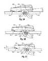
- FIG. 3Aillustrates a side view of a first possible cam for use with the present invention.
- FIG. 3Billustrates a side view of a second possible cam for use with the present invention.
- FIG. 3Cillustrates a side view of a third possible cam for use with the present invention.
- FIG. 4illustrates a side view of a first front mechanism elliptical exercise device having an adjustable footpad according to the present invention.
- FIG. 5illustrates a side view of a second front mechanism elliptical exercise device having an adjustable footpad according to the present invention.
- FIG. 6illustrates a perspective view of a mid-mechanism elliptical exercise device having an adjustable footpad according to the present invention.
- FIG. 7illustrates a side view of a strider exercise device having an adjustable footpad according to the present invention.
- the present inventiondescribes a simple and efficient way to vary the position of a footpad on an exercise device to accommodate the desires of different users, as well as the desires of individual users. More specifically, the present invention describes a footpad whose angular position is adjustable by a cam having at least two support sides.
- the camcan be positioned between the footpad and a link arm.
- the camcan be rotatable about an axis with at least two of the support sides being a different distance from the point about which the cam rotates.
- the orientation of the footpadcan be adjusted by a user by selectively rotating the cam so that the footpad is resting on different support sides of the cam.
- connectionis used broadly and encompasses both direct and indirect connections. Further, this term is not restricted to mechanical connections but also includes frictional, adhesive, magnetic and other connections.
- FIG. 1illustrates a perspective view of an exercise device 100 .
- exercise device 100is an elliptical machine.
- Exercise device 100comprises a frame 110 , which is configured to provide both structural and translational support to the components of the exercise device 100 , and also to interface with the ground.
- Frame 110includes a base member 112 and an upright member 114 .
- Upright member 114may support a console 116 .
- Base member 112has a forward end 112 a and a rearward end 112 b.
- Exercise device 100also includes a drive assembly 120 .
- Drive assembly 120can enclose in whole or in part a weighted flywheel 122 .
- Flywheel 122rotates about an axis 124 during performance of an exercise on exercise device 100 .
- Drive assembly 120is mounted at or near the rearward end 112 b of base member 112 . Because of the position of the drive assembly on the frame, exercise device 100 is commonly referred to as a “rear mechanism” or “rear drive” elliptical machine.
- the present inventioncan be used with elliptical machines having a drive assembly that is mounted at or near the forward end of the elliptical machine frame (see FIGS. 4 and 5 ) or somewhere between a forward end and rearward end of the elliptical machine frame (see FIG. 6 ).
- Exercise device 100has several link arms (e.g., 130 and 132 ).
- Link armscan be any part of an exercise device that moves during performance of an exercise on the device.
- exercise device 100includes at least two link arms: a foot support link arm 130 and a hand rail link arm 132 .
- Link arms 130 and 132are connected to frame 110 .
- foot support link arm 130is rotatably attached to drive assembly 120 at one end.
- foot support link arm 130is rotatably attached to hand rail link arm 132 .
- Hand rail link arm 132is rotatably attached to upright member 114 .
- Each of these link armsmoves during the performance of an exercise on exercise device 100 .
- Exercise device 100also includes a cam 140 .
- Cam 140has a triangular cross-sectional shape and includes three separate support sides, 142 a, 142 b, and 142 c (see FIGS. 2A-2C ).
- a support sidecan be any surface on a cam that at least partially supports a footpad and maintains that footpad in a desired position during the performance of an exercise.
- Cam 140is rotatably connected to foot support link arm 130 .
- a knob 144is attached to cam 140 to facilitate rotation of cam 140 about an axis 146 .
- a cammay but need not be capable of a full 360 degree rotation. Indeed, the cam may only be able to rotate 180 degrees, or less.
- Axis 146intersects cam 140 at a point 148 (see FIGS. 2A-2C ) that is not equidistance from each support side. Rather, different distances separate point 148 from at least two of support side 142 a, 142 b, and 142 c.
- a distance 150 aseparates point 148 from support side 142 a.
- a distance 150 bseparates point 148 from support side 142 b.
- a distance 150 cseparates point 148 from support side 142 c.
- Distance 150 ais larger than both distances 150 b and 150 c and distance 150 b is larger than distance 150 c.
- Exercise device 100also includes a footpad 160 .
- Footpad 160can be sized and configured to receive and support one or both feet of a user during the performance of an exercise on exercise device 100 .
- Footpad 160can have a toe end 160 a configured to receive a toe end of a user's foot and a heel end 160 b configured to receive a heal end of a user's foot.
- the upper surface of footpad 160can include a non-slip material 164 to help secure the feet of a user during performance of an exercise.
- footpad 160rotates about a closed, elliptical-shaped loop. Footpad 160 is pivotally connected to foot support link arm 130 at or near its toe end 160 a.
- Footpad 160also interacts with cam 140 .
- Cam 140can be positioned at any point under footpad 160 .
- a camcan be positioned below the toe end 160 a, the heel end 160 b, or somewhere between the toe and heel ends 160 a, 160 b of footpad 160 .
- the underside portion of footpad 160can include a support plate 162 (illustrated in FIGS. 2A-2C ).
- Support plate 162interfaces with a support side 142 a - c of cam 140 to provide a generally flat surface for cam 140 to support footpad 160 .
- footpad 160rests on cam 140 .
- a footpadcan be attached to a cam with a pin or clip or another device that provides a secure connection between the cam and the footpad.
- FIGS. 2A through 2Cillustrate the adjustability of footpad 160 .
- FIG. 2Ashows a hinge 166 pivotally connecting toe end 160 a of footpad 160 to foot support link arm 130 .
- FIG. 2Aalso shows cam 140 oriented such that support plate 162 of footpad 160 is resting on support side 142 a .
- distance 150 aseparates support side 142 a from point of rotation 148 .
- positioning support side 142 a below footpad 160creates an inclining angle ⁇ 1 between footpad 160 and foot support link arm 130 .
- FIG. 2Bshows cam 140 after a rotation of 120 degrees from its position in FIG. 2A .
- cam 140is oriented such that support plate 162 of footpad 160 is resting on support side 142 b.
- distance 150 bseparates support side 142 b from point of rotation 148 .
- Footpad 160is parallel to foot support link arm 130 when support side 142 b is positioned below footpad 160 .
- FIG. 2Cshows cam 140 after a rotation of 120 degrees from its position in FIG. 2B .
- cam 140is oriented such that support plate 162 of footpad 160 is resting on support side 142 c .
- distance 150 cseparates support side 142 c from point of rotation 148 .
- positioning support side 142 b below footpad 160creates a declining angle ⁇ 2 between footpad 160 and foot support link arm 130 .
- FIGS. 3A through 3Cillustrate additional cam shapes that are possible according to the present invention.
- Cam 240 in FIG. 3Ais generally tear-drop shaped.
- Cam 240has two support sides, 242 a and 242 b.
- Support sides 242 a and 242 b on cam 240are flat.
- a distance 250 aseparates support side 242 a from point 248 about which cam 240 rotates.
- a distance 250 bseparates support side 242 b from point 248 .
- Distances 250 a and 250 bare not the same.
- Cam 340 in FIG. 3Bis generally oval shaped.
- Cam 340has two support sides, 342 a and 342 b.
- Support sides 342 a and 342 b on cam 340are curved.
- a distance 350 aseparates support side 342 a from point 348 about which cam 340 rotates.
- a distance 350 bseparates support side 342 b from point 348 .
- Distances 350 a and 350 bare not the same.
- Cam 440 in FIG. 3Cis a square with rounded corners.
- Cam 440has four support sides, 442 a, 442 b, 442 c, and 442 d. Each of the support sides on cam 440 is flat.
- a distance 450 aseparates support side 442 a from point 448 about which cam 440 rotates.
- a distance 450 bseparates support side 442 b from point 448 .
- a distance 450 cseparates support side 442 c from point 448 .
- a distance 450 dseparates support side 442 d from point 448 . At least two of distances 250 a, 250 b, 250 c, and 250 d are not the same.
- FIG. 4illustrates a side view of a second exercise device 500 .
- Exercise device 500is also illustrated as a front mechanism elliptical machine.
- a link arm 530supports a footpad 560 .
- Link arm 530is rotatably connected to a drive assembly 520 at one end.
- Link arm 530is supported by and reciprocates along support rails 532 during performance of an exercise.
- Rollers 534 mounted on link arms 530provide a smooth connection between link arm 530 and support rails 532 .
- cam 540As can be seen in FIG. 4 , part of footpad 560 rests on a cam 540 , which is rotatably connected to link arm 530 .
- Cam 540has a number of support sides, which are not equidistant from the point 548 about which cam 540 rotates. Thus, the angle of footpad 560 is variable and depends on which support side of cam 540 is supporting footpad 560 .
- Cam 540may be similar or identical to the other cams described herein.
- FIG. 5illustrates a side view of a third exercise device 600 .
- Exercise device 600is also illustrated as a front mechanism elliptical machine.
- a link arm 630supports a footpad 660 .
- Link arm 630is rotatably connected to a second link arm 632 and drive assembly 620 .
- Link arm 630is also rotatably connected to a third link arm 634 . Each of these link arms moves during the performance of an exercise.
- cam 640As can be seen in FIG. 5 , part of footpad 660 rests on a cam 640 , which is rotatably connected to link arm 630 .
- Cam 640has a number of support sides, which are not equidistant from the point 648 about which cam 640 rotates.
- the angle of footpad 660is variable and depends on which support side of cam 640 is supporting footpad 660 .
- Cam 640may be similar or identical to the other cams described herein.
- FIG. 6illustrates a perspective view of a fourth exercise device 700 .
- Exercise device 700is illustrated as a mid-mechanism elliptical machine.
- a link arm 730supports a footpad 760 .
- Link arm 730is rotatably connected to a second link arm 732 at one end.
- Link arm 730is also connected to a drive assembly 720 .
- cam 740which is rotatably connected to link arm 730 .
- a userrotates cam 740 from the rearward end of link arm 730 .
- Cam 740has a number of support sides, which are not equidistant from the point 748 about which cam 740 rotates.
- the angle of footpad 760is variable and depends on which support side of cam 740 is supporting footpad 760 .
- Cam 740may be similar or identical to the other cams described herein.
- FIG. 7illustrates a side view of a fifth exercise device 800 .
- Exercise device 800is illustrated as a strider exercise machine.
- a link arm 830supports a footpad 860 .
- Link arm 830is rotatably connected to a second link arm 832 and to a drive assembly 820 .
- Link arm 830moves during the performance of an exercise.
- cam 840As can be seen in FIG. 7 , a part of footpad 860 rests on a cam 840 , which is rotatably connected to link arm 830 .
- Cam 840has a number of support sides, which are not equidistant from the point 848 about which cam 840 rotates. Thus, the angle of footpad 860 is variable and depends on which support side of cam 840 is supporting footpad 860 .
- Cam 840may be similar or identical to the other cams described herein
- the present inventionrelates to an adjustment mechanism for selectively changing the position of a footpad on an exercise device.
- the adjustment mechanism described in the present inventionis versatile, simple to make and use, can accommodate a large number of different positional settings, and is inexpensive to manufacture.
- the mechanism for varying the position of a footpad disclosed hereincan be used with nearly any exercise device that includes one or more footpads to support a user's feet during performance of an exercise.
- Several of these exercise devicesare identified herein (i.e., ellipticals, striders, steppers); however, the mechanism disclosed herein can be used with other exercise devices having footpads.
- some strength machineshave one or more footpads that may be linked by a cable or pulley system to a weight stack.
- the mechanism disclosed hereincould also be applied to this type of a strength machine to selectively adjust the position of the footpad.
- a footpadcan be pivotally connected to a supporting structure at or near its toe end or at or near its heal end.
- the mechanism for varying the position of a footpad disclosed hereinis simple to use. Adjusting a footpad using the mechanism disclosed herein may only require a user to rotate a knob or push a button.
- the knob or button for adjusting the position of a footpadcan be located somewhere convenient and easily reachable by a user.
- the knobcan be accessible on either side of a link arm. Alternatively, the knob may be positioned at an end of a link arm.
- a motormay be used to rotate a cam. In these embodiments, the motor may be activated by pressing a button located on the console or elsewhere on the exercise device.
- the mechanism for varying the position of a footpad disclosed hereincan also accommodate a large number of different positional settings.
- the mechanismmay include a cam that is circular, oval, or polygonal with any number of support sides.
- the support sidescan be flat or curved. Further the transition between two support sides on a cam may be sharp or rounded.
- the number of support sides on a cam that are not equidistant from the cam's rotational axiswill determine the number of different possible positions for a footpad.
- a cammay be rotatably connected to a footpad instead of a link arm.
- the support sides of a camcould rest on the link arm to which the footpad is pivotally connected.
- the camcould be selectively varied by a user based on the orientation of the cam relative to the footpad.
- the mechanism for varying the angle of a footpad disclosed hereinis easy to manufacture and inexpensive to produce.
- the mechanism for varying the angle of a footpad disclosed hereindoes not involve a large number of different moving parts, which can increase manufacturing cost and complexity.
- the mechanism disclosed hereininvolves a single cam, which can be rotated about a single axis to different positions.
- a cammay have three supports sides. Two of the three support sides may have the same distance to the point where a rotational axis intersects the cam, with the third support side having a different distance.
Landscapes
- Health & Medical Sciences (AREA)
- Cardiology (AREA)
- Vascular Medicine (AREA)
- General Health & Medical Sciences (AREA)
- Physical Education & Sports Medicine (AREA)
- Rehabilitation Tools (AREA)
Abstract
Description
Claims (20)
Priority Applications (1)
| Application Number | Priority Date | Filing Date | Title |
|---|---|---|---|
| US13/565,760US8894549B2 (en) | 2011-08-03 | 2012-08-02 | Exercise device with adjustable foot pad |
Applications Claiming Priority (2)
| Application Number | Priority Date | Filing Date | Title |
|---|---|---|---|
| US201161514816P | 2011-08-03 | 2011-08-03 | |
| US13/565,760US8894549B2 (en) | 2011-08-03 | 2012-08-02 | Exercise device with adjustable foot pad |
Publications (2)
| Publication Number | Publication Date |
|---|---|
| US20130196826A1 US20130196826A1 (en) | 2013-08-01 |
| US8894549B2true US8894549B2 (en) | 2014-11-25 |
Family
ID=48870711
Family Applications (1)
| Application Number | Title | Priority Date | Filing Date |
|---|---|---|---|
| US13/565,760Active2033-01-03US8894549B2 (en) | 2011-08-03 | 2012-08-02 | Exercise device with adjustable foot pad |
Country Status (1)
| Country | Link |
|---|---|
| US (1) | US8894549B2 (en) |
Cited By (54)
| Publication number | Priority date | Publication date | Assignee | Title |
|---|---|---|---|---|
| US20170216660A1 (en)* | 2016-02-03 | 2017-08-03 | Jody Newgard Lernihan | Portable sit-stand elliptical exercise machine |
| USD795975S1 (en) | 2016-01-22 | 2017-08-29 | Nautilus, Inc. | Handle |
| USD795974S1 (en) | 2016-01-22 | 2017-08-29 | Nautilus, Inc. | Handle |
| USD795973S1 (en) | 2016-01-22 | 2017-08-29 | Nautilus, Inc. | Handle for exercise machine |
| US20180050231A1 (en)* | 2016-08-17 | 2018-02-22 | Pt Motion Works, Inc. | Drive Mechanism with Foot Platform Angle Adjustment Mechanism for Elliptically-Driven Device |
| US10279212B2 (en) | 2013-03-14 | 2019-05-07 | Icon Health & Fitness, Inc. | Strength training apparatus with flywheel and related methods |
| USD853503S1 (en)* | 2017-06-27 | 2019-07-09 | Kai Bin Xing | Exercise device |
| USD854100S1 (en)* | 2017-06-27 | 2019-07-16 | Kai Bin Xing | Exercise device |
| US10369404B2 (en) | 2015-12-31 | 2019-08-06 | Nautilus, Inc. | Pedal assembly for exercise machine |
| US10493349B2 (en) | 2016-03-18 | 2019-12-03 | Icon Health & Fitness, Inc. | Display on exercise device |
| US10500473B2 (en) | 2016-10-10 | 2019-12-10 | Icon Health & Fitness, Inc. | Console positioning |
| US10561894B2 (en) | 2016-03-18 | 2020-02-18 | Icon Health & Fitness, Inc. | Treadmill with removable supports |
| US10625114B2 (en) | 2016-11-01 | 2020-04-21 | Icon Health & Fitness, Inc. | Elliptical and stationary bicycle apparatus including row functionality |
| US10625137B2 (en) | 2016-03-18 | 2020-04-21 | Icon Health & Fitness, Inc. | Coordinated displays in an exercise device |
| US10661114B2 (en) | 2016-11-01 | 2020-05-26 | Icon Health & Fitness, Inc. | Body weight lift mechanism on treadmill |
| US10729965B2 (en) | 2017-12-22 | 2020-08-04 | Icon Health & Fitness, Inc. | Audible belt guide in a treadmill |
| US10758767B2 (en) | 2013-12-26 | 2020-09-01 | Icon Health & Fitness, Inc. | Resistance mechanism in a cable exercise machine |
| US10786706B2 (en) | 2018-07-13 | 2020-09-29 | Icon Health & Fitness, Inc. | Cycling shoe power sensors |
| US10918905B2 (en) | 2016-10-12 | 2021-02-16 | Icon Health & Fitness, Inc. | Systems and methods for reducing runaway resistance on an exercise device |
| US10932517B2 (en) | 2014-03-10 | 2021-03-02 | Icon Health & Fitness, Inc. | Pressure sensor to quantify work |
| USD912167S1 (en)* | 2019-10-10 | 2021-03-02 | Kompan A/S | Multifunctional fitness machine |
| US10940360B2 (en) | 2015-08-26 | 2021-03-09 | Icon Health & Fitness, Inc. | Strength exercise mechanisms |
| US10953305B2 (en) | 2015-08-26 | 2021-03-23 | Icon Health & Fitness, Inc. | Strength exercise mechanisms |
| US10960261B2 (en)* | 2005-11-04 | 2021-03-30 | Johnson Health Tech Co., Ltd. | Stationary exercise apparatus |
| US10994173B2 (en) | 2016-05-13 | 2021-05-04 | Icon Health & Fitness, Inc. | Weight platform treadmill |
| US11000730B2 (en) | 2018-03-16 | 2021-05-11 | Icon Health & Fitness, Inc. | Elliptical exercise machine |
| US11013960B2 (en) | 2016-03-18 | 2021-05-25 | Icon Health & Fitness, Inc. | Exercise system including a stationary bicycle and a free weight cradle |
| US11033777B1 (en) | 2019-02-12 | 2021-06-15 | Icon Health & Fitness, Inc. | Stationary exercise machine |
| US11058914B2 (en) | 2016-07-01 | 2021-07-13 | Icon Health & Fitness, Inc. | Cooling methods for exercise equipment |
| US11058913B2 (en) | 2017-12-22 | 2021-07-13 | Icon Health & Fitness, Inc. | Inclinable exercise machine |
| US11187285B2 (en) | 2017-12-09 | 2021-11-30 | Icon Health & Fitness, Inc. | Systems and methods for selectively rotationally fixing a pedaled drivetrain |
| US11191995B2 (en) | 2016-12-30 | 2021-12-07 | Nautilus, Inc. | Pedal assembly for exercise machine |
| US11244751B2 (en) | 2012-10-19 | 2022-02-08 | Finish Time Holdings, Llc | Method and device for providing a person with training data of an athlete as the athlete is performing a swimming workout |
| US11298577B2 (en) | 2019-02-11 | 2022-04-12 | Ifit Inc. | Cable and power rack exercise machine |
| US11326673B2 (en) | 2018-06-11 | 2022-05-10 | Ifit Inc. | Increased durability linear actuator |
| US11451108B2 (en) | 2017-08-16 | 2022-09-20 | Ifit Inc. | Systems and methods for axial impact resistance in electric motors |
| US11534651B2 (en) | 2019-08-15 | 2022-12-27 | Ifit Inc. | Adjustable dumbbell system |
| US11534654B2 (en) | 2019-01-25 | 2022-12-27 | Ifit Inc. | Systems and methods for an interactive pedaled exercise device |
| US11673036B2 (en) | 2019-11-12 | 2023-06-13 | Ifit Inc. | Exercise storage system |
| US11794070B2 (en) | 2019-05-23 | 2023-10-24 | Ifit Inc. | Systems and methods for cooling an exercise device |
| US11850497B2 (en) | 2019-10-11 | 2023-12-26 | Ifit Inc. | Modular exercise device |
| US11878199B2 (en) | 2021-02-16 | 2024-01-23 | Ifit Inc. | Safety mechanism for an adjustable dumbbell |
| US11931621B2 (en) | 2020-03-18 | 2024-03-19 | Ifit Inc. | Systems and methods for treadmill drift avoidance |
| US11951377B2 (en) | 2020-03-24 | 2024-04-09 | Ifit Inc. | Leaderboard with irregularity flags in an exercise machine system |
| US12029961B2 (en) | 2020-03-24 | 2024-07-09 | Ifit Inc. | Flagging irregularities in user performance in an exercise machine system |
| US12029935B2 (en) | 2021-08-19 | 2024-07-09 | Ifit Inc. | Adjustment mechanism for an adjustable kettlebell |
| US12176009B2 (en) | 2021-12-30 | 2024-12-24 | Ifit Inc. | Systems and methods for synchronizing workout equipment with video files |
| US12219201B2 (en) | 2021-08-05 | 2025-02-04 | Ifit Inc. | Synchronizing video workout programs across multiple devices |
| US12263371B2 (en) | 2021-04-27 | 2025-04-01 | Ifit Inc. | Devices, systems, and methods for rotating a tread belt in two directions |
| US12280294B2 (en) | 2021-10-15 | 2025-04-22 | Ifit Inc. | Magnetic clutch for a pedaled drivetrain |
| US12350547B2 (en) | 2022-02-28 | 2025-07-08 | Ifit Inc. | Devices, systems, and methods for moving a movable step through a transition zone |
| US12350573B2 (en) | 2021-04-27 | 2025-07-08 | Ifit Inc. | Systems and methods for cross-training on exercise devices |
| US12409375B2 (en) | 2022-03-18 | 2025-09-09 | Ifit Inc. | Systems and methods for haptic simulation in incline exercise devices |
| US12433815B2 (en) | 2020-10-02 | 2025-10-07 | Ifit Inc. | Massage roller with pressure sensors |
Families Citing this family (13)
| Publication number | Priority date | Publication date | Assignee | Title |
|---|---|---|---|---|
| CN104548487B (en)* | 2013-10-16 | 2018-10-23 | 北京知康优美科技有限公司 | A kind of intelligent elliptical machine based on technology of Internet of things |
| WO2015191445A1 (en) | 2014-06-09 | 2015-12-17 | Icon Health & Fitness, Inc. | Cable system incorporated into a treadmill |
| US10258828B2 (en) | 2015-01-16 | 2019-04-16 | Icon Health & Fitness, Inc. | Controls for an exercise device |
| US10272317B2 (en) | 2016-03-18 | 2019-04-30 | Icon Health & Fitness, Inc. | Lighted pace feature in a treadmill |
| US10471299B2 (en) | 2016-07-01 | 2019-11-12 | Icon Health & Fitness, Inc. | Systems and methods for cooling internal exercise equipment components |
| US10441844B2 (en) | 2016-07-01 | 2019-10-15 | Icon Health & Fitness, Inc. | Cooling systems and methods for exercise equipment |
| US10207148B2 (en) | 2016-10-12 | 2019-02-19 | Icon Health & Fitness, Inc. | Systems and methods for reducing runaway resistance on an exercise device |
| US10376736B2 (en) | 2016-10-12 | 2019-08-13 | Icon Health & Fitness, Inc. | Cooling an exercise device during a dive motor runway condition |
| TWI646997B (en) | 2016-11-01 | 2019-01-11 | 美商愛康運動與健康公司 | Distance sensor for console positioning |
| TWI680782B (en) | 2016-12-05 | 2020-01-01 | 美商愛康運動與健康公司 | Offsetting treadmill deck weight during operation |
| USD949253S1 (en)* | 2018-06-20 | 2022-04-19 | Thane Ip Limited | Exercise machine |
| USD1029140S1 (en)* | 2021-10-18 | 2024-05-28 | Decathlon | Elliptical machine |
| USD1027073S1 (en)* | 2021-10-18 | 2024-05-14 | Decathlon | Elliptical machine |
Citations (14)
| Publication number | Priority date | Publication date | Assignee | Title |
|---|---|---|---|---|
| US5651754A (en)* | 1996-07-30 | 1997-07-29 | Chen; Ping | Wheel assembly adapted to be mounted on a wheel-bearing tube of an exerciser without the need for a locking bolt |
| US6106441A (en)* | 1999-09-08 | 2000-08-22 | Chen; Ping | Height adjustable foot anchoring wheel assembly |
| US6171216B1 (en)* | 1999-08-16 | 2001-01-09 | Leao Wang | Angle-adjusting device for treadmill supporting frame |
| US6743155B2 (en)* | 2001-07-31 | 2004-06-01 | Forhouse Corporation | Angle-adjusting device for a treadmill frame |
| US6849034B2 (en)* | 2003-05-23 | 2005-02-01 | Paul William Eschenbach | Turnabout climber exercise apparatus |
| US6945912B2 (en) | 2003-03-14 | 2005-09-20 | Levi Avraham Y | Exercise treadmill with slope adjustment |
| US7276017B2 (en)* | 2005-09-26 | 2007-10-02 | Michael Lin | Pedal angle adjustable device for exercisers |
| US20080064571A1 (en)* | 2006-09-08 | 2008-03-13 | Sunny Lee | Exercise machine |
| US7377879B1 (en) | 2007-02-14 | 2008-05-27 | Michael Lin | Pedal adjustable system for exercisers |
| US7563203B2 (en)* | 1998-09-25 | 2009-07-21 | Icon Ip, Inc. | Treadmill with adjustable cushioning members |
| US7604573B2 (en) | 2005-04-14 | 2009-10-20 | Icon Ip, Inc. | Method and system for varying stride in an elliptical exercise machine |
| US7665388B2 (en) | 2007-08-21 | 2010-02-23 | Michael Lin | Pedal adjustable device for exercisers |
| US7674205B2 (en) | 2007-05-08 | 2010-03-09 | Icon Ip, Inc. | Elliptical exercise machine with adjustable foot motion |
| US8801582B2 (en)* | 2012-03-05 | 2014-08-12 | Dyaco International Inc. | Treadmill |
- 2012
- 2012-08-02USUS13/565,760patent/US8894549B2/enactiveActive
Patent Citations (15)
| Publication number | Priority date | Publication date | Assignee | Title |
|---|---|---|---|---|
| US5651754A (en)* | 1996-07-30 | 1997-07-29 | Chen; Ping | Wheel assembly adapted to be mounted on a wheel-bearing tube of an exerciser without the need for a locking bolt |
| US7563203B2 (en)* | 1998-09-25 | 2009-07-21 | Icon Ip, Inc. | Treadmill with adjustable cushioning members |
| US6171216B1 (en)* | 1999-08-16 | 2001-01-09 | Leao Wang | Angle-adjusting device for treadmill supporting frame |
| US6106441A (en)* | 1999-09-08 | 2000-08-22 | Chen; Ping | Height adjustable foot anchoring wheel assembly |
| US6743155B2 (en)* | 2001-07-31 | 2004-06-01 | Forhouse Corporation | Angle-adjusting device for a treadmill frame |
| US6945912B2 (en) | 2003-03-14 | 2005-09-20 | Levi Avraham Y | Exercise treadmill with slope adjustment |
| US6849034B2 (en)* | 2003-05-23 | 2005-02-01 | Paul William Eschenbach | Turnabout climber exercise apparatus |
| US7604573B2 (en) | 2005-04-14 | 2009-10-20 | Icon Ip, Inc. | Method and system for varying stride in an elliptical exercise machine |
| US7901330B2 (en) | 2005-04-14 | 2011-03-08 | Icon Ip, Inc. | Method and system for varying stride in an elliptical exercise machine |
| US7276017B2 (en)* | 2005-09-26 | 2007-10-02 | Michael Lin | Pedal angle adjustable device for exercisers |
| US20080064571A1 (en)* | 2006-09-08 | 2008-03-13 | Sunny Lee | Exercise machine |
| US7377879B1 (en) | 2007-02-14 | 2008-05-27 | Michael Lin | Pedal adjustable system for exercisers |
| US7674205B2 (en) | 2007-05-08 | 2010-03-09 | Icon Ip, Inc. | Elliptical exercise machine with adjustable foot motion |
| US7665388B2 (en) | 2007-08-21 | 2010-02-23 | Michael Lin | Pedal adjustable device for exercisers |
| US8801582B2 (en)* | 2012-03-05 | 2014-08-12 | Dyaco International Inc. | Treadmill |
Cited By (85)
| Publication number | Priority date | Publication date | Assignee | Title |
|---|---|---|---|---|
| US11529544B2 (en) | 2005-11-04 | 2022-12-20 | Johnson Health Tech Co., Ltd. | Stationary exercise apparatus |
| US10960261B2 (en)* | 2005-11-04 | 2021-03-30 | Johnson Health Tech Co., Ltd. | Stationary exercise apparatus |
| US12340891B2 (en) | 2012-10-19 | 2025-06-24 | Finish Time Network LLC | System and method for providing a trainer with live training data of an individual as the individual is performing a training workout |
| US11810656B2 (en) | 2012-10-19 | 2023-11-07 | Finish Time Holdings, Llc | System for providing a coach with live training data of an athlete as the athlete is training |
| US11923066B2 (en) | 2012-10-19 | 2024-03-05 | Finish Time Holdings, Llc | System and method for providing a trainer with live training data of an individual as the individual is performing a training workout |
| US11322240B2 (en) | 2012-10-19 | 2022-05-03 | Finish Time Holdings, Llc | Method and device for providing a person with training data of an athlete as the athlete is performing a running workout |
| US11244751B2 (en) | 2012-10-19 | 2022-02-08 | Finish Time Holdings, Llc | Method and device for providing a person with training data of an athlete as the athlete is performing a swimming workout |
| US10953268B1 (en) | 2013-03-14 | 2021-03-23 | Icon Health & Fitness, Inc. | Strength training apparatus |
| US10709925B2 (en) | 2013-03-14 | 2020-07-14 | Icon Health & Fitness, Inc. | Strength training apparatus |
| US10279212B2 (en) | 2013-03-14 | 2019-05-07 | Icon Health & Fitness, Inc. | Strength training apparatus with flywheel and related methods |
| US11338169B2 (en) | 2013-03-14 | 2022-05-24 | IFIT, Inc. | Strength training apparatus |
| US11878206B2 (en) | 2013-03-14 | 2024-01-23 | Ifit Inc. | Strength training apparatus |
| US10967214B1 (en) | 2013-12-26 | 2021-04-06 | Icon Health & Fitness, Inc. | Cable exercise machine |
| US10758767B2 (en) | 2013-12-26 | 2020-09-01 | Icon Health & Fitness, Inc. | Resistance mechanism in a cable exercise machine |
| US10932517B2 (en) | 2014-03-10 | 2021-03-02 | Icon Health & Fitness, Inc. | Pressure sensor to quantify work |
| US11700905B2 (en) | 2014-03-10 | 2023-07-18 | Ifit Inc. | Pressure sensor to quantify work |
| US10953305B2 (en) | 2015-08-26 | 2021-03-23 | Icon Health & Fitness, Inc. | Strength exercise mechanisms |
| US10940360B2 (en) | 2015-08-26 | 2021-03-09 | Icon Health & Fitness, Inc. | Strength exercise mechanisms |
| US10369404B2 (en) | 2015-12-31 | 2019-08-06 | Nautilus, Inc. | Pedal assembly for exercise machine |
| USD795974S1 (en) | 2016-01-22 | 2017-08-29 | Nautilus, Inc. | Handle |
| USD795973S1 (en) | 2016-01-22 | 2017-08-29 | Nautilus, Inc. | Handle for exercise machine |
| USD795975S1 (en) | 2016-01-22 | 2017-08-29 | Nautilus, Inc. | Handle |
| US20170216660A1 (en)* | 2016-02-03 | 2017-08-03 | Jody Newgard Lernihan | Portable sit-stand elliptical exercise machine |
| US10220246B2 (en)* | 2016-02-03 | 2019-03-05 | Jody Newgard Lernihan | Portable sit-stand elliptical exercise machine |
| US12029944B2 (en) | 2016-03-18 | 2024-07-09 | Ifit Inc. | Stationary exercise machine configured to execute a programmed workout with aerobic portions and lifting portions |
| US10625137B2 (en) | 2016-03-18 | 2020-04-21 | Icon Health & Fitness, Inc. | Coordinated displays in an exercise device |
| US12023549B2 (en) | 2016-03-18 | 2024-07-02 | Ifit Inc. | Stationary exercise machine configured to execute a programmed workout with aerobic portions and lifting portions |
| US10493349B2 (en) | 2016-03-18 | 2019-12-03 | Icon Health & Fitness, Inc. | Display on exercise device |
| US11565148B2 (en) | 2016-03-18 | 2023-01-31 | Ifit Inc. | Treadmill with a scale mechanism in a motor cover |
| US11013960B2 (en) | 2016-03-18 | 2021-05-25 | Icon Health & Fitness, Inc. | Exercise system including a stationary bicycle and a free weight cradle |
| US12029943B2 (en) | 2016-03-18 | 2024-07-09 | Ifit Inc. | Stationary exercise machine configured to execute a programmed workout with aerobic portions and lifting portions |
| US10561894B2 (en) | 2016-03-18 | 2020-02-18 | Icon Health & Fitness, Inc. | Treadmill with removable supports |
| US11794075B2 (en) | 2016-03-18 | 2023-10-24 | Ifit Inc. | Stationary exercise machine configured to execute a programmed workout with aerobic portions and lifting portions |
| US11779812B2 (en) | 2016-05-13 | 2023-10-10 | Ifit Inc. | Treadmill configured to automatically determine user exercise movement |
| US10994173B2 (en) | 2016-05-13 | 2021-05-04 | Icon Health & Fitness, Inc. | Weight platform treadmill |
| US11058914B2 (en) | 2016-07-01 | 2021-07-13 | Icon Health & Fitness, Inc. | Cooling methods for exercise equipment |
| US10695607B2 (en)* | 2016-08-17 | 2020-06-30 | Pt Motion Works, Inc. | Drive mechanism with foot platform angle adjustment mechanism for elliptically-driven device |
| US20180050231A1 (en)* | 2016-08-17 | 2018-02-22 | Pt Motion Works, Inc. | Drive Mechanism with Foot Platform Angle Adjustment Mechanism for Elliptically-Driven Device |
| US10500473B2 (en) | 2016-10-10 | 2019-12-10 | Icon Health & Fitness, Inc. | Console positioning |
| US10918905B2 (en) | 2016-10-12 | 2021-02-16 | Icon Health & Fitness, Inc. | Systems and methods for reducing runaway resistance on an exercise device |
| US10661114B2 (en) | 2016-11-01 | 2020-05-26 | Icon Health & Fitness, Inc. | Body weight lift mechanism on treadmill |
| US10625114B2 (en) | 2016-11-01 | 2020-04-21 | Icon Health & Fitness, Inc. | Elliptical and stationary bicycle apparatus including row functionality |
| US11191995B2 (en) | 2016-12-30 | 2021-12-07 | Nautilus, Inc. | Pedal assembly for exercise machine |
| USD853503S1 (en)* | 2017-06-27 | 2019-07-09 | Kai Bin Xing | Exercise device |
| USD854100S1 (en)* | 2017-06-27 | 2019-07-16 | Kai Bin Xing | Exercise device |
| US11451108B2 (en) | 2017-08-16 | 2022-09-20 | Ifit Inc. | Systems and methods for axial impact resistance in electric motors |
| US12270441B2 (en) | 2017-12-09 | 2025-04-08 | Ifit Inc. | Systems and methods for selectively rotationally fixing a pedaled drivetrain |
| US11187285B2 (en) | 2017-12-09 | 2021-11-30 | Icon Health & Fitness, Inc. | Systems and methods for selectively rotationally fixing a pedaled drivetrain |
| US11708874B2 (en) | 2017-12-09 | 2023-07-25 | Ifit Inc. | Systems and methods for selectively rotationally fixing a pedaled drivetrain |
| US11680611B2 (en) | 2017-12-09 | 2023-06-20 | Ifit Inc. | Systems and methods for selectively rotationally fixing a pedaled drivetrain |
| US11058913B2 (en) | 2017-12-22 | 2021-07-13 | Icon Health & Fitness, Inc. | Inclinable exercise machine |
| US10729965B2 (en) | 2017-12-22 | 2020-08-04 | Icon Health & Fitness, Inc. | Audible belt guide in a treadmill |
| US11000730B2 (en) | 2018-03-16 | 2021-05-11 | Icon Health & Fitness, Inc. | Elliptical exercise machine |
| US11596830B2 (en) | 2018-03-16 | 2023-03-07 | Ifit Inc. | Elliptical exercise machine |
| US11326673B2 (en) | 2018-06-11 | 2022-05-10 | Ifit Inc. | Increased durability linear actuator |
| US10786706B2 (en) | 2018-07-13 | 2020-09-29 | Icon Health & Fitness, Inc. | Cycling shoe power sensors |
| US12005315B2 (en) | 2018-07-13 | 2024-06-11 | Ifit Inc. | Cycling shoe power sensors |
| US11534654B2 (en) | 2019-01-25 | 2022-12-27 | Ifit Inc. | Systems and methods for an interactive pedaled exercise device |
| US11452903B2 (en) | 2019-02-11 | 2022-09-27 | Ifit Inc. | Exercise machine |
| US11642564B2 (en) | 2019-02-11 | 2023-05-09 | Ifit Inc. | Exercise machine |
| US11298577B2 (en) | 2019-02-11 | 2022-04-12 | Ifit Inc. | Cable and power rack exercise machine |
| US11033777B1 (en) | 2019-02-12 | 2021-06-15 | Icon Health & Fitness, Inc. | Stationary exercise machine |
| US11058918B1 (en) | 2019-02-12 | 2021-07-13 | Icon Health & Fitness, Inc. | Producing a workout video to control a stationary exercise machine |
| US11426633B2 (en) | 2019-02-12 | 2022-08-30 | Ifit Inc. | Controlling an exercise machine using a video workout program |
| US11951358B2 (en) | 2019-02-12 | 2024-04-09 | Ifit Inc. | Encoding exercise machine control commands in subtitle streams |
| US11794070B2 (en) | 2019-05-23 | 2023-10-24 | Ifit Inc. | Systems and methods for cooling an exercise device |
| US11534651B2 (en) | 2019-08-15 | 2022-12-27 | Ifit Inc. | Adjustable dumbbell system |
| USD912167S1 (en)* | 2019-10-10 | 2021-03-02 | Kompan A/S | Multifunctional fitness machine |
| US11850497B2 (en) | 2019-10-11 | 2023-12-26 | Ifit Inc. | Modular exercise device |
| US12296247B2 (en) | 2019-10-11 | 2025-05-13 | Ifit Inc. | Modular exercise device |
| US11673036B2 (en) | 2019-11-12 | 2023-06-13 | Ifit Inc. | Exercise storage system |
| US11931621B2 (en) | 2020-03-18 | 2024-03-19 | Ifit Inc. | Systems and methods for treadmill drift avoidance |
| US11951377B2 (en) | 2020-03-24 | 2024-04-09 | Ifit Inc. | Leaderboard with irregularity flags in an exercise machine system |
| US12029961B2 (en) | 2020-03-24 | 2024-07-09 | Ifit Inc. | Flagging irregularities in user performance in an exercise machine system |
| US12433815B2 (en) | 2020-10-02 | 2025-10-07 | Ifit Inc. | Massage roller with pressure sensors |
| US11878199B2 (en) | 2021-02-16 | 2024-01-23 | Ifit Inc. | Safety mechanism for an adjustable dumbbell |
| US12239872B2 (en) | 2021-02-16 | 2025-03-04 | Ifit Inc. | Safety mechanism for an adjustable dumbbell |
| US12263371B2 (en) | 2021-04-27 | 2025-04-01 | Ifit Inc. | Devices, systems, and methods for rotating a tread belt in two directions |
| US12350573B2 (en) | 2021-04-27 | 2025-07-08 | Ifit Inc. | Systems and methods for cross-training on exercise devices |
| US12219201B2 (en) | 2021-08-05 | 2025-02-04 | Ifit Inc. | Synchronizing video workout programs across multiple devices |
| US12029935B2 (en) | 2021-08-19 | 2024-07-09 | Ifit Inc. | Adjustment mechanism for an adjustable kettlebell |
| US12280294B2 (en) | 2021-10-15 | 2025-04-22 | Ifit Inc. | Magnetic clutch for a pedaled drivetrain |
| US12176009B2 (en) | 2021-12-30 | 2024-12-24 | Ifit Inc. | Systems and methods for synchronizing workout equipment with video files |
| US12350547B2 (en) | 2022-02-28 | 2025-07-08 | Ifit Inc. | Devices, systems, and methods for moving a movable step through a transition zone |
| US12409375B2 (en) | 2022-03-18 | 2025-09-09 | Ifit Inc. | Systems and methods for haptic simulation in incline exercise devices |
Also Published As
| Publication number | Publication date |
|---|---|
| US20130196826A1 (en) | 2013-08-01 |
Similar Documents
| Publication | Publication Date | Title |
|---|---|---|
| US8894549B2 (en) | Exercise device with adjustable foot pad | |
| US10207147B2 (en) | Pedal path of a stepping machine | |
| US9050498B2 (en) | Exercise assemblies having foot pedal members that are movable along user defined paths | |
| CA2411657C (en) | Exercise device for cross training | |
| US8419598B2 (en) | Adjustable total body cross-training exercise device | |
| US8465398B2 (en) | Elliptical exercise apparatus | |
| TWI320719B (en) | Exercise machine | |
| US10220246B2 (en) | Portable sit-stand elliptical exercise machine | |
| US7749137B2 (en) | Variable stride exercise device | |
| US7794362B2 (en) | Exercise device with adjustable stride | |
| EP2188022B1 (en) | Seated exercise apparatus | |
| US7314432B2 (en) | Stepping exercise device | |
| US20170056717A1 (en) | Pedal Path of a Stepping Machine | |
| US20040097339A1 (en) | Adjustable stride elliptical motion exercise machine and associated methods | |
| US7758472B2 (en) | Exercise device ramp roller retainer | |
| WO2017009801A1 (en) | Multifunctional cardio and toning exercise machine | |
| US10780314B2 (en) | Exercise apparatus | |
| KR101115545B1 (en) | A exercise device for rehabilitation | |
| US7108638B2 (en) | Exercise device | |
| TWI294294B (en) | ||
| US10716965B2 (en) | Exercise machine | |
| US11266873B1 (en) | Bicycle-type exercise apparatus | |
| TW200924820A (en) | Exercise apparatus | |
| EP1582238A1 (en) | Stepping exercise device | |
| KR20110107417A (en) | Posture Balance Training System with Ankle Muscle Strengthening Function |
Legal Events
| Date | Code | Title | Description |
|---|---|---|---|
| AS | Assignment | Owner name:ICON HEALTH & FITNESS, INC., UTAH Free format text:ASSIGNMENT OF ASSIGNORS INTEREST;ASSIGNOR:COLLEDGE, MATTHEW D.;REEL/FRAME:028877/0845 Effective date:20120823 | |
| STCF | Information on status: patent grant | Free format text:PATENTED CASE | |
| AS | Assignment | Owner name:BANK OF AMERICA, N.A., AS ADMINISTRATIVE AGENT, MA Free format text:SECURITY AGREEMENT;ASSIGNORS:ICON HEALTH & FITNESS, INC.;ICON IP, INC.;REEL/FRAME:036104/0833 Effective date:20150710 | |
| AS | Assignment | Owner name:ICON IP, INC., UTAH Free format text:RELEASE OF SECURITY INTEREST IN PATENTS;ASSIGNOR:BANK OF AMERICA, N.A., ACTING IN ITS CAPACITY AS AGENT FOR THE LENDERS;REEL/FRAME:039584/0575 Effective date:20160803 Owner name:FREE MOTION FITNESS, INC., UTAH Free format text:RELEASE OF SECURITY INTEREST IN PATENTS;ASSIGNOR:BANK OF AMERICA, N.A., ACTING IN ITS CAPACITY AS AGENT FOR THE LENDERS;REEL/FRAME:039584/0575 Effective date:20160803 Owner name:ICON - ALTRA LLC, UTAH Free format text:RELEASE OF SECURITY INTEREST IN PATENTS;ASSIGNOR:BANK OF AMERICA, N.A., ACTING IN ITS CAPACITY AS AGENT FOR THE LENDERS;REEL/FRAME:039584/0575 Effective date:20160803 Owner name:ICON DU CANADA INC., CANADA Free format text:RELEASE OF SECURITY INTEREST IN PATENTS;ASSIGNOR:BANK OF AMERICA, N.A., ACTING IN ITS CAPACITY AS AGENT FOR THE LENDERS;REEL/FRAME:039584/0575 Effective date:20160803 Owner name:HF HOLDINGS, INC., UTAH Free format text:RELEASE OF SECURITY INTEREST IN PATENTS;ASSIGNOR:BANK OF AMERICA, N.A., ACTING IN ITS CAPACITY AS AGENT FOR THE LENDERS;REEL/FRAME:039584/0575 Effective date:20160803 Owner name:UNIVERSAL TECHNICAL SERVICES, UTAH Free format text:RELEASE OF SECURITY INTEREST IN PATENTS;ASSIGNOR:BANK OF AMERICA, N.A., ACTING IN ITS CAPACITY AS AGENT FOR THE LENDERS;REEL/FRAME:039584/0575 Effective date:20160803 Owner name:ICON INTERNATIONAL HOLDINGS, INC., UTAH Free format text:RELEASE OF SECURITY INTEREST IN PATENTS;ASSIGNOR:BANK OF AMERICA, N.A., ACTING IN ITS CAPACITY AS AGENT FOR THE LENDERS;REEL/FRAME:039584/0575 Effective date:20160803 Owner name:ICON HEALTH & FITNESS, INC, UTAH Free format text:RELEASE OF SECURITY INTEREST IN PATENTS;ASSIGNOR:BANK OF AMERICA, N.A., ACTING IN ITS CAPACITY AS AGENT FOR THE LENDERS;REEL/FRAME:039584/0575 Effective date:20160803 | |
| AS | Assignment | Owner name:JPMORGAN CHASE BANK, N.A., AS ADMINISTRATIVE AGENT Free format text:PATENT SECURITY AGREEMENT;ASSIGNORS:ICON HEALTH FITNESS, INC.;HF HOLDINGS, INC.;UNIVERSAL TECHNICAL SERVICES;AND OTHERS;REEL/FRAME:039669/0311 Effective date:20160803 Owner name:JPMORGAN CHASE BANK, N.A., AS ADMINISTRATIVE AGENT Free format text:PATENT SECURITY AGREEMENT;ASSIGNORS:ICON HEALTH & FITNESS, INC.;HF HOLDINGS, INC.;UNIVERSAL TECHNICAL SERVICES;AND OTHERS;REEL/FRAME:039669/0311 Effective date:20160803 | |
| MAFP | Maintenance fee payment | Free format text:PAYMENT OF MAINTENANCE FEE, 4TH YEAR, LARGE ENTITY (ORIGINAL EVENT CODE: M1551) Year of fee payment:4 | |
| AS | Assignment | Owner name:ICON IP, INC., UTAH Free format text:TERMINATION AND RELEASE OF SECURITY INTEREST IN PATENT RIGHTS;ASSIGNOR:JPMORGAN CHASE BANK, N.A., AS ADMINISTRATIVE AGENT;REEL/FRAME:052671/0737 Effective date:20200427 Owner name:ICON HEALTH & FITNESS, INC., UTAH Free format text:TERMINATION AND RELEASE OF SECURITY INTEREST IN PATENT RIGHTS;ASSIGNOR:JPMORGAN CHASE BANK, N.A., AS ADMINISTRATIVE AGENT;REEL/FRAME:052671/0737 Effective date:20200427 Owner name:JPMORGAN CHASE BANK, N.A., AS ADMINISTRATIVE AGENT, ILLINOIS Free format text:PATENT SECURITY AGREEMENT;ASSIGNOR:ICON HEALTH & FITNESS, INC.;REEL/FRAME:053548/0453 Effective date:20200427 | |
| AS | Assignment | Owner name:BANK OF AMERICA, N.A., AS ADMINISTRATIVE AGENT, CALIFORNIA Free format text:SECURITY INTEREST;ASSIGNOR:ICON HEALTH & FITNESS, INC.;REEL/FRAME:056238/0818 Effective date:20210512 | |
| AS | Assignment | Owner name:ICON HEALTH & FITNESS, INC., UTAH Free format text:TERMINATION AND RELEASE OF SECURITY INTEREST IN PATENTS;ASSIGNOR:JPMORGAN CHASE BANK, N.A., AS ADMINISTRATIVE AGENT;REEL/FRAME:056654/0951 Effective date:20210512 | |
| AS | Assignment | Owner name:IFIT INC, UTAH Free format text:CHANGE OF NAME;ASSIGNOR:ICON HEALTH & FITNESS, INC.;REEL/FRAME:058742/0476 Effective date:20210809 | |
| AS | Assignment | Owner name:IFIT INC., UTAH Free format text:TO CORRECT AN ERROR IN A COVER SHEET PREVIOUSLY RECORDED AT REEL/FRAME 058742/0476 - CORRECT ASSIGNEE NAME IFIT INC TO IFIT INC;ASSIGNOR:ICON HEALTH & FITNESS, INC.;REEL/FRAME:058957/0531 Effective date:20210809 | |
| AS | Assignment | Owner name:PLC AGENT LLC, MASSACHUSETTS Free format text:SECURITY INTEREST;ASSIGNOR:IFIT INC.;REEL/FRAME:059249/0466 Effective date:20220224 | |
| AS | Assignment | Owner name:ICON PREFERRED HOLDINGS, L.P., UTAH Free format text:INTELLECTUAL PROPERTY SECURITY AGREEMENT;ASSIGNOR:IFIT INC.;REEL/FRAME:059633/0313 Effective date:20220224 | |
| AS | Assignment | Owner name:ICON PREFERRED HOLDINGS, L.P., NEW YORK Free format text:CORRECTIVE ASSIGNMENT TO CORRECT THE THE ASSIGNEE'S ADDRESS PREVIOUSLY RECORDED AT REEL: 059633 FRAME: 0313. ASSIGNOR(S) HEREBY CONFIRMS THE ASSIGNMENT;ASSIGNOR:IFIT INC.;REEL/FRAME:060512/0315 Effective date:20220224 | |
| AS | Assignment | Owner name:LC9 CONNECTED HOLDINGS, LP, CONNECTICUT Free format text:SECURITY INTEREST;ASSIGNORS:IFIT INC.;ICON IP, INC.;REEL/FRAME:059857/0830 Effective date:20220224 | |
| MAFP | Maintenance fee payment | Free format text:PAYMENT OF MAINTENANCE FEE, 8TH YEAR, LARGE ENTITY (ORIGINAL EVENT CODE: M1552); ENTITY STATUS OF PATENT OWNER: LARGE ENTITY Year of fee payment:8 | |
| AS | Assignment | Owner name:LC9 CONNECTED HOLDINGS, LP, CONNECTICUT Free format text:SECURITY INTEREST;ASSIGNORS:IFIT INC.;ICON IP, INC.;REEL/FRAME:066094/0529 Effective date:20231214 | |
| AS | Assignment | Owner name:CERBERUS BUSINESS FINANCE AGENCY, LLC, NEW YORK Free format text:SECURITY INTEREST;ASSIGNOR:IFIT, INC.;REEL/FRAME:071278/0707 Effective date:20250512 | |
| AS | Assignment | Owner name:ICON IP INC., UTAH Free format text:RELEASE BY SECURED PARTY;ASSIGNOR:ICON PREFERRED HOLDINGS, L.P.;REEL/FRAME:071336/0725 Effective date:20250512 Owner name:IFIT INC., UTAH Free format text:RELEASE BY SECURED PARTY;ASSIGNOR:ICON PREFERRED HOLDINGS, L.P.;REEL/FRAME:071336/0725 Effective date:20250512 | |
| AS | Assignment | Owner name:ICON IP, INC., UTAH Free format text:RELEASE BY SECURED PARTY;ASSIGNOR:BANK OF AMERICA, N.A.;REEL/FRAME:071351/0624 Effective date:20250512 Owner name:IFIT, INC. (F/K/A ICON HEALTH & FITNESS, INC.), UTAH Free format text:RELEASE BY SECURED PARTY;ASSIGNOR:BANK OF AMERICA, N.A.;REEL/FRAME:071351/0624 Effective date:20250512 Owner name:ICON IP, INC., UTAH Free format text:RELEASE BY SECURED PARTY;ASSIGNOR:PLC AGENT LLC;REEL/FRAME:071358/0584 Effective date:20250512 Owner name:IFIT INC., UTAH Free format text:RELEASE BY SECURED PARTY;ASSIGNOR:PLC AGENT LLC;REEL/FRAME:071358/0584 Effective date:20250512 | |
| AS | Assignment | Owner name:ICON IP INC., UTAH Free format text:RELEASE BY SECURED PARTY;ASSIGNOR:LC9 CONNECTED HOLDINGS, LP;REEL/FRAME:071407/0001 Effective date:20250512 Owner name:IFIT INC., UTAH Free format text:RELEASE BY SECURED PARTY;ASSIGNOR:LC9 CONNECTED HOLDINGS, LP;REEL/FRAME:071407/0001 Effective date:20250512 | |
| AS | Assignment | Owner name:ICON IP INC., UTAH Free format text:RELEASE OF INTELLECTUAL PROPERTY SECURITY INTEREST (4TH LIEN);ASSIGNOR:LC9 CONNECTED HOLDINGS, LP;REEL/FRAME:071429/0479 Effective date:20250512 Owner name:IFIT INC., UTAH Free format text:RELEASE OF INTELLECTUAL PROPERTY SECURITY INTEREST (4TH LIEN);ASSIGNOR:LC9 CONNECTED HOLDINGS, LP;REEL/FRAME:071429/0479 Effective date:20250512 |