US8894354B2 - Fan - Google Patents
FanDownload PDFInfo
- Publication number
- US8894354B2 US8894354B2US13/207,212US201113207212AUS8894354B2US 8894354 B2US8894354 B2US 8894354B2US 201113207212 AUS201113207212 AUS 201113207212AUS 8894354 B2US8894354 B2US 8894354B2
- Authority
- US
- United States
- Prior art keywords
- casing
- impeller
- fan
- housing
- impeller housing
- Prior art date
- Legal status (The legal status is an assumption and is not a legal conclusion. Google has not performed a legal analysis and makes no representation as to the accuracy of the status listed.)
- Expired - Fee Related, expires
Links
Images


Classifications
- F—MECHANICAL ENGINEERING; LIGHTING; HEATING; WEAPONS; BLASTING
- F04—POSITIVE - DISPLACEMENT MACHINES FOR LIQUIDS; PUMPS FOR LIQUIDS OR ELASTIC FLUIDS
- F04D—NON-POSITIVE-DISPLACEMENT PUMPS
- F04D25/00—Pumping installations or systems
- F04D25/02—Units comprising pumps and their driving means
- F04D25/08—Units comprising pumps and their driving means the working fluid being air, e.g. for ventilation
- F—MECHANICAL ENGINEERING; LIGHTING; HEATING; WEAPONS; BLASTING
- F04—POSITIVE - DISPLACEMENT MACHINES FOR LIQUIDS; PUMPS FOR LIQUIDS OR ELASTIC FLUIDS
- F04D—NON-POSITIVE-DISPLACEMENT PUMPS
- F04D29/00—Details, component parts, or accessories
- F04D29/08—Sealings
- F04D29/16—Sealings between pressure and suction sides
- F04D29/161—Sealings between pressure and suction sides especially adapted for elastic fluid pumps
- F—MECHANICAL ENGINEERING; LIGHTING; HEATING; WEAPONS; BLASTING
- F04—POSITIVE - DISPLACEMENT MACHINES FOR LIQUIDS; PUMPS FOR LIQUIDS OR ELASTIC FLUIDS
- F04D—NON-POSITIVE-DISPLACEMENT PUMPS
- F04D29/00—Details, component parts, or accessories
- F04D29/08—Sealings
- F04D29/083—Sealings especially adapted for elastic fluid pumps
- F—MECHANICAL ENGINEERING; LIGHTING; HEATING; WEAPONS; BLASTING
- F04—POSITIVE - DISPLACEMENT MACHINES FOR LIQUIDS; PUMPS FOR LIQUIDS OR ELASTIC FLUIDS
- F04D—NON-POSITIVE-DISPLACEMENT PUMPS
- F04D29/00—Details, component parts, or accessories
- F04D29/60—Mounting; Assembling; Disassembling
- F04D29/62—Mounting; Assembling; Disassembling of radial or helico-centrifugal pumps
- F04D29/624—Mounting; Assembling; Disassembling of radial or helico-centrifugal pumps especially adapted for elastic fluid pumps
- F04D29/626—Mounting or removal of fans
- F—MECHANICAL ENGINEERING; LIGHTING; HEATING; WEAPONS; BLASTING
- F04—POSITIVE - DISPLACEMENT MACHINES FOR LIQUIDS; PUMPS FOR LIQUIDS OR ELASTIC FLUIDS
- F04D—NON-POSITIVE-DISPLACEMENT PUMPS
- F04D29/00—Details, component parts, or accessories
- F04D29/66—Combating cavitation, whirls, noise, vibration or the like; Balancing
- F04D29/661—Combating cavitation, whirls, noise, vibration or the like; Balancing especially adapted for elastic fluid pumps
- F04D29/668—Combating cavitation, whirls, noise, vibration or the like; Balancing especially adapted for elastic fluid pumps damping or preventing mechanical vibrations
- F—MECHANICAL ENGINEERING; LIGHTING; HEATING; WEAPONS; BLASTING
- F04—POSITIVE - DISPLACEMENT MACHINES FOR LIQUIDS; PUMPS FOR LIQUIDS OR ELASTIC FLUIDS
- F04D—NON-POSITIVE-DISPLACEMENT PUMPS
- F04D29/00—Details, component parts, or accessories
- F04D29/66—Combating cavitation, whirls, noise, vibration or the like; Balancing
- F04D29/68—Combating cavitation, whirls, noise, vibration or the like; Balancing by influencing boundary layers
- F04D29/681—Combating cavitation, whirls, noise, vibration or the like; Balancing by influencing boundary layers especially adapted for elastic fluid pumps
- F—MECHANICAL ENGINEERING; LIGHTING; HEATING; WEAPONS; BLASTING
- F04—POSITIVE - DISPLACEMENT MACHINES FOR LIQUIDS; PUMPS FOR LIQUIDS OR ELASTIC FLUIDS
- F04F—PUMPING OF FLUID BY DIRECT CONTACT OF ANOTHER FLUID OR BY USING INERTIA OF FLUID TO BE PUMPED; SIPHONS
- F04F5/00—Jet pumps, i.e. devices in which flow is induced by pressure drop caused by velocity of another fluid flow
- F04F5/14—Jet pumps, i.e. devices in which flow is induced by pressure drop caused by velocity of another fluid flow the inducing fluid being elastic fluid
- F04F5/16—Jet pumps, i.e. devices in which flow is induced by pressure drop caused by velocity of another fluid flow the inducing fluid being elastic fluid displacing elastic fluids
Definitions
- the present inventionrelates to a portable fan. Particularly, but not exclusively, the present invention relates to a floor or table-top fan, such as a desk, tower or pedestal fan.
- a conventional domestic fantypically includes a set of blades or vanes mounted for rotation about an axis, and drive apparatus for rotating the set of blades to generate an air flow.
- the movement and circulation of the air flowcreates a ‘wind chill’ or breeze and, as a result, the user experiences a cooling effect as heat is dissipated through convection and evaporation.
- the bladesare generated located within a cage which allows an air flow to pass through the housing while preventing users from coming into contact with the rotating blades during use of the fan.
- WO 2009/030879describes a fan assembly which does not use caged blades to project air from the fan assembly. Instead, the fan assembly comprises a cylindrical base which houses a motor-driven impeller for drawing a primary air flow into the base, and an annular nozzle connected to the base and comprising an annular air outlet through which the primary air flow is emitted from the fan.
- the nozzledefines a central opening through which air in the local environment of the fan assembly is drawn by the primary air flow emitted from the mouth, amplifying the primary air flow.
- the impelleris located within an impeller housing, and the motor for driving the impeller is located within a motor bucket which is mounted on the impeller housing.
- the impeller housingis supported within the base by a plurality of angularly spaced supports. Each support is, in turn, mounted on a respective support surface extending radially inwardly from the inner surface of the base.
- a lip sealis located on the outer surface of the impeller housing for engaging the inner surface of the base.
- the present inventionprovides a fan comprising a casing having an air inlet and an air outlet, an impeller housing located within the casing, an impeller located within the impeller housing for generating an air flow along a path extending from the air inlet to the air outlet through the impeller housing, a motor housing connected to the impeller housing, a motor located within the motor housing for driving the impeller, and a bellows support for supporting the impeller housing within the casing, the bellows support being mounted on a seat connected to the casing, the bellows support extending about the impeller housing and forming a seal between the impeller housing and the casing.
- a bellows support for mounting the impeller housing within the casingcan reduce the transmission of vibrations from the motor housing to the casing in comparison to when a plurality of angularly spaced supports are used to mount the impeller housing within the casing.
- the bellows supportcan also form a seal between the casing and the impeller housing to prevent air from leaking back towards the air inlet of the casing along a path extending between the casing and the impeller housing, thereby forcing the pressurized air flow generated by the impeller to pass to the air outlet of the casing.
- a separate lip sealis not required for sealing between the impeller housing and the casing, the number of components of the fan, and therefore the manufacturing and assembly costs, can be reduced.
- the bellows supportis preferably arranged within the casing so as to bear evenly thereabout the weight of the impeller, impeller housing, motor and motor housing.
- the bellows supportpreferably comprises an upper end connected to the impeller housing, and a lower end disposed on the seat.
- the upper end of the bellows supportmay comprise a groove for retaining a generally annular rib located on the outer surface of the impeller housing, thereby forming a seal between the impeller housing and the bellows support.
- the bellows supportpreferably comprises a sealing member, preferably in the form of a lip seal, for engaging the inner surface of the casing.
- the lip sealis preferably integral with the bellows support.
- the fanpreferably comprises means for inhibiting rotation of the bellows support relative to the casing.
- the seatmay comprise a plurality of angularly spaced support surfaces and the rotation inhibiting means may comprise at least one rotation inhibiting member connected to the bellows support and located between adjacent support surfaces so that any rotational force acting on the bellows support urges the rotation inhibiting member against a side wall of one of these adjacent support surfaces.
- the rotation inhibiting meanscomprises a plurality of such rotation inhibiting members each located adjacent a respective one of the adjacent support surfaces.
- the bellows supportis preferably substantially co-axial with the impeller.
- the fanpreferably comprises means for inhibiting radial displacement of the bellows support relative to the casing away from its co-axial alignment with the impeller.
- the radial displacement inhibiting meanscomprises a collar connected to the bellows. This collar preferably depends downwardly from the lower end of the bellows support. The collar may be surrounded by the seat so that any radial force acting on the bellows support urges the collar against the seat to inhibit radial displacement of the bellows support relative to the seat.
- the seatpreferably extends radially inwardly from the inner surface of the casing.
- the seatis preferably integral with the casing.
- the impeller housingpreferably comprises a shroud extending about and substantially concentric with the impeller.
- the present inventionalso provides a fan comprising a casing having an air inlet and an air outlet, an impeller housing located within the casing, an impeller located within the impeller housing for generating an air flow along a path extending from the air inlet to the air outlet through the impeller housing, a motor housing connected to the impeller housing, a motor located within the motor housing for driving the impeller, and a bellows extending about the impeller housing and forming a seal between the impeller housing and the casing.
- FIG. 1is a front view of a fan
- FIG. 2is a front perspective view, from above, of the air outlet of the fan;
- FIG. 3is a top view of a central part of the fan
- FIG. 4is a side sectional view of the lower part of the fan, taken along line A-A in FIG. 3 ;
- FIG. 5is a front perspective view, from above, of the impeller casing and the bellows support of the fan;
- FIG. 6is a rear perspective view, from above, of the impeller casing and the bellows support ember of the fan;
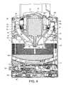
- FIG. 7is a top view of the motor casing section of the base of the fan, housing the impeller casing and bellows support;
- FIG. 8is a side sectional view of the motor casing section, impeller casing and bellows support, taken along line B-B in FIG. 7 ;
- FIG. 9is a rear view of the motor casing section of the base of the fan, housing the impeller casing and bellows support;
- FIG. 10is a bottom sectional view of the motor casing section, impeller casing and bellows support, taken along line C-C in FIG. 9 .
- FIG. 1is a front view of a fan 10 .
- the fancomprises a body 12 having an air inlet 14 in the form of a plurality of apertures formed in the outer casing 16 of the body 12 , and through which a primary air flow is drawn into the body 12 from the external environment.
- An annular casing 18 having an air outlet 20 for emitting the primary air flow from the fan 10is connected to the body 12 .
- the body 12further comprises a user interface for allowing a user to control the operation of the fan 10 .
- the user interfacecomprises a plurality of user-operable buttons 22 , 24 and a user-operable dial 26 .
- the casing 14comprises an annular outer casing section 28 connected to and extending about an annular inner casing section 30 .
- the annular sections 28 , 30 of the casing 14extend about and define an opening 32 .
- Each of these sectionsmay be formed from a plurality of connected parts, but in this embodiment each of the outer casing section 28 and the inner casing section 30 is formed from a respective, single molded part.
- the outer casing section 28is inserted into a slot located at the front of the inner casing section 30 , as illustrated in FIGS. 3 and 4 .
- the outer and inner casing sections 28 , 30may be connected together using an adhesive introduced to the slot.
- the outer casing section 28comprises a base 34 which is connected to the open upper end of the casing 16 of the body 12 , and which has an open lower end for receiving the primary air flow from the body 12 .
- the outer casing section 28 and the inner casing section 30together define an annular interior passage 35 (shown in FIG. 4 ) for conveying the primary air flow to the air outlet 20 .
- the interior passage 35is bounded by the internal surface of the outer casing section 28 and the internal surface of the inner casing section 30 .
- the base 34 of the outer casing section 28is shaped to convey the primary air flow into the interior passage 35 of the casing 14 .
- the air outlet 20is located towards the rear of the casing 14 , and is arranged to emit the primary air flow towards the front of the fan 10 , through the opening 32 .
- the air outlet 20extends at least partially about the opening 32 , and preferably surrounds the opening 32 .
- the air outlet 20is defined by overlapping, or facing, portions of the internal surface of the outer casing section 28 and the external surface of the inner casing section 30 , respectively, and is in the form of an annular slot, preferably having a relatively constant width in the range from 0.5 to 5 mm. In this example the air outlet has a width of around 1 mm.
- Spacersmay be spaced about the air outlet 20 for urging apart the overlapping portions of the outer casing section 28 and the inner casing section 30 to maintain the width of the air outlet 20 at the desired level. These spacers may be integral with either the outer casing section 28 or the inner casing section 30 .
- the air outlet 20is shaped to direct the primary air flow over the external surface of the inner casing section 30 .
- the external surface of the inner casing section 30comprises a Coanda surface 36 located adjacent the air outlet 20 and over which the air outlet 20 directs the air emitted from the fan 10 , a diffuser surface 38 located downstream of the Coanda surface 36 and a guide surface 40 located downstream of the diffuser surface 38 .
- the diffuser surface 38is arranged to taper away from the central axis X of the opening 32 in such a way so as to assist the flow of air emitted from the fan 10 .
- the angle subtended between the diffuser surface 38 and the central axis X of the opening 32is in the range from 5 to 25°, and in this example is around 15°.
- the guide surface 40is arranged at an angle to the diffuser surface 38 to further assist the efficient delivery of a cooling air flow from the fan 10 .
- the guide surface 40is preferably arranged substantially parallel to the central axis X of the opening 32 to present a substantially flat and substantially smooth face to the air flow emitted from the air outlet 20 .
- a visually appealing tapered surface 42is located downstream from the guide surface 40 , terminating at a tip surface 44 lying substantially perpendicular to the central axis X of the opening 32 .
- the angle subtended between the tapered surface 42 and the central axis X of the opening 32is preferably around 45°.
- FIG. 4illustrates a side sectional view through the body 12 of the fan 10 .
- the body 12comprises a substantially cylindrical main body section 50 mounted on a substantially cylindrical lower body section 52 .
- the main body section 50 and the lower body section 52are preferably formed from plastics material.
- the main body section 50 and the lower body section 52preferably have substantially the same external diameter so that the external surface of the upper body section 20 is substantially flush with the external surface of the lower body section 52 .
- the main body section 50comprises the air inlet 14 through which the primary air flow enters the fan assembly 10 .
- the air inlet 14comprises an array of apertures formed in the main body section 50 .
- the air inlet 14may comprise one or more grilles or meshes mounted within windows formed in the main body section 50 .
- the main body section 50is open at the upper end (as illustrated) thereof to provide an air outlet 54 through which the primary air flow is exhausted from the body 12 .
- the main body section 50may be tilted relative to the lower body section 52 to adjust the direction in which the primary air flow is emitted from the fan assembly 10 .
- the upper surface of the lower body section 52 and the lower surface of the main body section 50may be provided with interconnecting features which allow the main body section 50 to move relative to the lower body section 52 while preventing the main body section 50 from being lifted from the lower body section 52 .
- the lower body section 52 and the main body section 50may comprise interlocking L-shaped members.
- the lower body section 52is mounted on a base 56 for engaging a surface on which the fan assembly 10 is located.
- the lower body 52comprises the aforementioned user interface and a control circuit, indicated generally at 58 , for controlling various functions of the fan 10 in response to operation of the user interface.
- the lower body section 22also houses a mechanism for oscillating the lower body section 22 relative to the base 36 .
- the operation of the oscillation mechanismis controlled by the control circuit 58 in response to the user's depression of the button 24 of the user interface.
- the range of each oscillation cycle of the lower body section 22 relative to the base 36is preferably between 60° and 120°, and the oscillation mechanism is arranged to perform around 3 to 5 oscillation cycles per minute.
- a mains power cable (not shown) for supplying electrical power to the fan 10extends through an aperture formed in the base 56 .
- the main body section 50houses an impeller 60 for drawing the primary air flow through the air inlet 14 and into the body 12 .
- the impeller 60is connected to a rotary shaft 62 extending outwardly from a motor 64 .
- the motor 64is a DC brushless motor having a speed which is variable by the control circuit 58 in response to user manipulation of the dial 26 .
- the maximum speed of the motor 64is preferably in the range from 5,000 to 10,000 rpm.
- the motor 64is housed within a motor housing.
- the motor housingcomprises a lower section 66 which supports the motor 64 , and an upper section 68 connected to the lower section 66 .
- the shaft 62protrudes through an aperture formed in the lower section 66 of the motor housing to allow the impeller to be connected to the shaft 62 .
- the upper section 68 of the motor housingcomprises a removable hatch 70 through which the motor 64 is inserted into the motor housing.
- the upper section 68comprises an annular diffuser 72 having a plurality of blades for receiving the primary air flow exhausted from the impeller 64 and for guiding the air flow to the air outlet 54 of the main body section 50 .
- the motor housingis supported within the main body section 50 by an impeller shroud 74 .
- the shroud 74is generally frusto-conical in shape, and comprises an air inlet 76 at the relatively small, outwardly flared lower end thereof (as illustrated) for receiving the primary air flow, and an air outlet 78 at the relatively large, upper end thereof (as illustrated) which is located immediately upstream from the diffuser 72 when the motor housing is supported within the shroud 74 .
- the impeller 60 and the shroud 74are shaped so when the impeller 60 and motor housing are supported by the shroud 74 , the blade tips of the impeller 60 are in close proximity to, but does not contact, the inner surface of the shroud 74 , and the impeller 60 is substantially co-axial with the shroud 74 .
- the shroud 74comprises a groove 80 extending about the air outlet 78 for receiving a downwardly depending projection 82 of the outer wall 84 of the diffuser 72 .
- a first aperture 86is formed in the upper end of the shroud 74
- a second aperture 88is formed in the outer wall 84 of the diffuser 72 which aligns with the first aperture 86 when the motor housing is supported by the shroud 74 to enable a cable (not shown) to pass from the control circuit 58 to the motor 64 .
- Both the groove 80 and the projection 82extend less that 360°, and by substantially the same amount, about the rotational axis of the shaft 62 and the impeller 64 so that the apertures 86 , 88 are accurately aligned during assembly.
- the groove 80extends around the rotational axis of the shaft 62 and the impeller 64 by an angle of around 320°.
- the impeller 64 , motor housing and shroud 74are also preferably formed from plastics material.
- the shroud 74is supported within the main body section 50 by a bellows support 90 .
- the bellows support 90is preferably formed from elastically deformable material, and in this example is formed from natural rubber.
- the bellows support 90extends about the shroud 74 .
- the inner surface of the upper end (as illustrated) of the bellows support 90comprises a groove 92 for receiving a rib 94 formed on the outer surface of the shroud 74 .
- both the groove 92 and the projection 94extend less that 360°, and by substantially the same amount, about the rotational axis of the shaft 62 and the impeller 64 to define an aperture 96 between the shroud 74 and the bellows support 90 through which the cable passes between the control circuit 58 and the motor 64 .
- This aperture 96is sealed by a grommet 97 which is located around the cable so that there is an air-tight seal between the shroud 74 and the bellows support 90 .
- the groove 92also extends around the rotational axis of the shaft 62 and the impeller 64 by an angle of around 320°.
- the lower end (as illustrated) of the bellows support 90is annular in shape, and located on a seat 98 connected to the main body section 50 .
- the seat 98comprises a plurality of support surfaces 98 a , 98 b , 98 c each extending radially inwardly from, and integral with, the inner surface of the main body section 50 .
- the lower end of the bellows support 90comprises an array of strengthening radial ribs 100 , and a pair of lugs 102 which depend from the lower end of the bellows support 90 .
- the lugs 102are located between support surfaces 98 b , 98 c of the seat 98 , with each lug 102 being located angularly adjacent a respective one of the support surfaces 98 b , 98 c to inhibit rotation of the bellows support 90 relative to the main body section 50 .
- the support surfaces 98 b , 98 c and the lugs 102are shaped so that the lugs 102 can only be inserted between the support surfaces 98 b , 98 c , which ensures correct angular location of the shroud 74 and the bellows support 90 within the main body section 50 .
- a collar 104also depends from the lower end of the bellows support 90 .
- the collar 104has an outer diameter which is substantially the same as the diameter of the radially inner edges of the seat 98 so that when the bellows support 90 is mounted on the seat 98 , the collar 104 engages the inner edges of the support surfaces 98 a , 98 b , 98 c of the seat 98 . This ensures that the shroud 74 and bellows support 90 are accurately radially aligned within the main body section 50 , preferably so that the shroud 74 is co-axial with the main body section 50 .
- the bellows support 90also comprises a flexible sealing member extending about the outer surface thereof for engaging the inner surface of the main body section 50 .
- the flexible sealing memberis preferably integral with the bellows support 90 , and is preferably in the form of an annular lip seal 106 .
- the outer diameter of the lip seal 106is preferably greater than the diameter of the inner surface of the main body section 50 so that the tip of the lip seal 106 is urged against the inner surface of the main body section 50 when the bellows support 90 is inserted into the casing 16 to form an air tight seal between the motor casing section 50 and the bellows support 90 .
- the body 12further comprises at least one silencing member for reducing noise emissions from the body 12 .
- the main body section 50comprises a disc of acoustic foam 108 between the air inlet 14 and the bottom surface 110 of the main body section 50 .
- the userpresses button 22 of the user interface, in response to which the control circuit 58 activates the motor 64 to rotate the impeller 60 .
- the rotation of the impeller 60causes a primary air flow to be drawn into the body 12 through the air inlet 14 .
- the usermay control the speed of the motor 64 , and therefore the rate at which air is drawn into the body 12 through the air inlet 14 , by manipulating the dial 26 .
- the primary air flow generated by the impeller 60may be between 20 and 30 liters per second.
- the rotation of the impeller 60 by the motor 64generates vibrations which are transferred through the motor housing and the shroud 74 to the bellows support 90 .
- the upper end of the bellows support 90is able to move both axially and radially relative to the lower end of the bellows support 90 , which inhibits the transfer of these vibrations to the seat 98 lower end of the bellows support 90 , and thus to the main body section 50 and the remainder of the body 12 of the fan 10 .
- the primary air flowpasses sequentially between the impeller 60 and the shroud 74 , and through the diffuser 72 , before passing through the air outlet 54 of the body 12 and into the casing 14 .
- the engagement between the lip seal 106 and the inner surface of the main body section 50prevents the primary air flow from returning to the air inlet 76 of the shroud 74 along a path extending between the inner surface of the main body section 50 and the outer surface of the shroud 74 .
- the pressure of the primary air flow at the air outlet 54 of the body 12may be at least 150 Pa, and is preferably in the range from 250 to 1.5 kPa.
- the primary air flowis divided into two air streams which pass in opposite directions around the opening 32 of the casing 14 .
- airis emitted through the air outlet 20 .
- the primary air flow emitted from the air outlet 20is directed over the Coanda surface 36 of the casing 14 , causing a secondary air flow to be generated by the entrainment of air from the external environment, specifically from the region around the air outlet 20 and from around the rear of the casing 14 .
- This secondary air flowpasses through the central opening 32 of the casing 14 , where it combines with the primary air flow to produce a total air flow, or air current, projected forward from the casing 14 .
Landscapes
- Engineering & Computer Science (AREA)
- Mechanical Engineering (AREA)
- General Engineering & Computer Science (AREA)
- Physics & Mathematics (AREA)
- Fluid Mechanics (AREA)
- Structures Of Non-Positive Displacement Pumps (AREA)
Abstract
Description
This application claims the priority of United Kingdom Application No. 1014831.0, filed Sep. 7, 2010, the entire contents of which are incorporated herein by reference.
The present invention relates to a portable fan. Particularly, but not exclusively, the present invention relates to a floor or table-top fan, such as a desk, tower or pedestal fan.
A conventional domestic fan typically includes a set of blades or vanes mounted for rotation about an axis, and drive apparatus for rotating the set of blades to generate an air flow. The movement and circulation of the air flow creates a ‘wind chill’ or breeze and, as a result, the user experiences a cooling effect as heat is dissipated through convection and evaporation. The blades are generated located within a cage which allows an air flow to pass through the housing while preventing users from coming into contact with the rotating blades during use of the fan.
WO 2009/030879 describes a fan assembly which does not use caged blades to project air from the fan assembly. Instead, the fan assembly comprises a cylindrical base which houses a motor-driven impeller for drawing a primary air flow into the base, and an annular nozzle connected to the base and comprising an annular air outlet through which the primary air flow is emitted from the fan. The nozzle defines a central opening through which air in the local environment of the fan assembly is drawn by the primary air flow emitted from the mouth, amplifying the primary air flow.
Our co-pending patent application PCT/GB2010/050270 also describes such a fan assembly. Within the base, the impeller is located within an impeller housing, and the motor for driving the impeller is located within a motor bucket which is mounted on the impeller housing. The impeller housing is supported within the base by a plurality of angularly spaced supports. Each support is, in turn, mounted on a respective support surface extending radially inwardly from the inner surface of the base. In order to provide an air tight seal between the impeller housing and the base, a lip seal is located on the outer surface of the impeller housing for engaging the inner surface of the base.
In a first aspect, the present invention provides a fan comprising a casing having an air inlet and an air outlet, an impeller housing located within the casing, an impeller located within the impeller housing for generating an air flow along a path extending from the air inlet to the air outlet through the impeller housing, a motor housing connected to the impeller housing, a motor located within the motor housing for driving the impeller, and a bellows support for supporting the impeller housing within the casing, the bellows support being mounted on a seat connected to the casing, the bellows support extending about the impeller housing and forming a seal between the impeller housing and the casing.
We have found that the use of a bellows support for mounting the impeller housing within the casing can reduce the transmission of vibrations from the motor housing to the casing in comparison to when a plurality of angularly spaced supports are used to mount the impeller housing within the casing. The bellows support can also form a seal between the casing and the impeller housing to prevent air from leaking back towards the air inlet of the casing along a path extending between the casing and the impeller housing, thereby forcing the pressurized air flow generated by the impeller to pass to the air outlet of the casing. As a separate lip seal is not required for sealing between the impeller housing and the casing, the number of components of the fan, and therefore the manufacturing and assembly costs, can be reduced.
The bellows support is preferably arranged within the casing so as to bear evenly thereabout the weight of the impeller, impeller housing, motor and motor housing. The bellows support preferably comprises an upper end connected to the impeller housing, and a lower end disposed on the seat. For example, the upper end of the bellows support may comprise a groove for retaining a generally annular rib located on the outer surface of the impeller housing, thereby forming a seal between the impeller housing and the bellows support. The bellows support preferably comprises a sealing member, preferably in the form of a lip seal, for engaging the inner surface of the casing. The lip seal is preferably integral with the bellows support.
The fan preferably comprises means for inhibiting rotation of the bellows support relative to the casing. For example, the seat may comprise a plurality of angularly spaced support surfaces and the rotation inhibiting means may comprise at least one rotation inhibiting member connected to the bellows support and located between adjacent support surfaces so that any rotational force acting on the bellows support urges the rotation inhibiting member against a side wall of one of these adjacent support surfaces. In a preferred embodiment, the rotation inhibiting means comprises a plurality of such rotation inhibiting members each located adjacent a respective one of the adjacent support surfaces.
The bellows support is preferably substantially co-axial with the impeller. The fan preferably comprises means for inhibiting radial displacement of the bellows support relative to the casing away from its co-axial alignment with the impeller. In a preferred embodiment the radial displacement inhibiting means comprises a collar connected to the bellows. This collar preferably depends downwardly from the lower end of the bellows support. The collar may be surrounded by the seat so that any radial force acting on the bellows support urges the collar against the seat to inhibit radial displacement of the bellows support relative to the seat.
The seat preferably extends radially inwardly from the inner surface of the casing. The seat is preferably integral with the casing.
The impeller housing preferably comprises a shroud extending about and substantially concentric with the impeller.
In a second aspect, the present invention also provides a fan comprising a casing having an air inlet and an air outlet, an impeller housing located within the casing, an impeller located within the impeller housing for generating an air flow along a path extending from the air inlet to the air outlet through the impeller housing, a motor housing connected to the impeller housing, a motor located within the motor housing for driving the impeller, and a bellows extending about the impeller housing and forming a seal between the impeller housing and the casing.
Features described above in connection with the first aspect of the invention are equally applicable to the second aspect of the invention, and vice versa.
Preferred features of the invention will now be described, by way of example only, with reference to the accompanying drawings, in which:
As also shown inFIG. 2 , thecasing 14 comprises an annularouter casing section 28 connected to and extending about an annularinner casing section 30. Theannular sections casing 14 extend about and define anopening 32. Each of these sections may be formed from a plurality of connected parts, but in this embodiment each of theouter casing section 28 and theinner casing section 30 is formed from a respective, single molded part. During assembly, theouter casing section 28 is inserted into a slot located at the front of theinner casing section 30, as illustrated inFIGS. 3 and4. The outer andinner casing sections outer casing section 28 comprises abase 34 which is connected to the open upper end of thecasing 16 of thebody 12, and which has an open lower end for receiving the primary air flow from thebody 12.
Theouter casing section 28 and theinner casing section 30 together define an annular interior passage35 (shown inFIG. 4 ) for conveying the primary air flow to theair outlet 20. Theinterior passage 35 is bounded by the internal surface of theouter casing section 28 and the internal surface of theinner casing section 30. Thebase 34 of theouter casing section 28 is shaped to convey the primary air flow into theinterior passage 35 of thecasing 14.
Theair outlet 20 is located towards the rear of thecasing 14, and is arranged to emit the primary air flow towards the front of thefan 10, through theopening 32. Theair outlet 20 extends at least partially about theopening 32, and preferably surrounds theopening 32. Theair outlet 20 is defined by overlapping, or facing, portions of the internal surface of theouter casing section 28 and the external surface of theinner casing section 30, respectively, and is in the form of an annular slot, preferably having a relatively constant width in the range from 0.5 to 5 mm. In this example the air outlet has a width of around 1 mm. Spacers may be spaced about theair outlet 20 for urging apart the overlapping portions of theouter casing section 28 and theinner casing section 30 to maintain the width of theair outlet 20 at the desired level. These spacers may be integral with either theouter casing section 28 or theinner casing section 30.
Theair outlet 20 is shaped to direct the primary air flow over the external surface of theinner casing section 30. The external surface of theinner casing section 30 comprises aCoanda surface 36 located adjacent theair outlet 20 and over which theair outlet 20 directs the air emitted from thefan 10, adiffuser surface 38 located downstream of theCoanda surface 36 and aguide surface 40 located downstream of thediffuser surface 38. Thediffuser surface 38 is arranged to taper away from the central axis X of theopening 32 in such a way so as to assist the flow of air emitted from thefan 10. The angle subtended between thediffuser surface 38 and the central axis X of theopening 32 is in the range from 5 to 25°, and in this example is around 15°. Theguide surface 40 is arranged at an angle to thediffuser surface 38 to further assist the efficient delivery of a cooling air flow from thefan 10. Theguide surface 40 is preferably arranged substantially parallel to the central axis X of theopening 32 to present a substantially flat and substantially smooth face to the air flow emitted from theair outlet 20. A visually appealing taperedsurface 42 is located downstream from theguide surface 40, terminating at atip surface 44 lying substantially perpendicular to the central axis X of theopening 32. The angle subtended between thetapered surface 42 and the central axis X of theopening 32 is preferably around 45°.
Themain body section 50 comprises theair inlet 14 through which the primary air flow enters thefan assembly 10. In this embodiment theair inlet 14 comprises an array of apertures formed in themain body section 50. Alternatively, theair inlet 14 may comprise one or more grilles or meshes mounted within windows formed in themain body section 50. Themain body section 50 is open at the upper end (as illustrated) thereof to provide anair outlet 54 through which the primary air flow is exhausted from thebody 12.
Themain body section 50 may be tilted relative to thelower body section 52 to adjust the direction in which the primary air flow is emitted from thefan assembly 10. For example, the upper surface of thelower body section 52 and the lower surface of themain body section 50 may be provided with interconnecting features which allow themain body section 50 to move relative to thelower body section 52 while preventing themain body section 50 from being lifted from thelower body section 52. For example, thelower body section 52 and themain body section 50 may comprise interlocking L-shaped members.
Thelower body section 52 is mounted on abase 56 for engaging a surface on which thefan assembly 10 is located. Thelower body 52 comprises the aforementioned user interface and a control circuit, indicated generally at58, for controlling various functions of thefan 10 in response to operation of the user interface. Thelower body section 22 also houses a mechanism for oscillating thelower body section 22 relative to thebase 36. The operation of the oscillation mechanism is controlled by thecontrol circuit 58 in response to the user's depression of thebutton 24 of the user interface. The range of each oscillation cycle of thelower body section 22 relative to thebase 36 is preferably between 60° and 120°, and the oscillation mechanism is arranged to perform around 3 to 5 oscillation cycles per minute. A mains power cable (not shown) for supplying electrical power to thefan 10 extends through an aperture formed in thebase 56.
Themain body section 50 houses animpeller 60 for drawing the primary air flow through theair inlet 14 and into thebody 12. Theimpeller 60 is connected to arotary shaft 62 extending outwardly from amotor 64. In this embodiment, themotor 64 is a DC brushless motor having a speed which is variable by thecontrol circuit 58 in response to user manipulation of thedial 26. The maximum speed of themotor 64 is preferably in the range from 5,000 to 10,000 rpm.
Themotor 64 is housed within a motor housing. The motor housing comprises alower section 66 which supports themotor 64, and anupper section 68 connected to thelower section 66. Theshaft 62 protrudes through an aperture formed in thelower section 66 of the motor housing to allow the impeller to be connected to theshaft 62. Theupper section 68 of the motor housing comprises aremovable hatch 70 through which themotor 64 is inserted into the motor housing. Theupper section 68 comprises anannular diffuser 72 having a plurality of blades for receiving the primary air flow exhausted from theimpeller 64 and for guiding the air flow to theair outlet 54 of themain body section 50.
The motor housing is supported within themain body section 50 by animpeller shroud 74. Theshroud 74 is generally frusto-conical in shape, and comprises anair inlet 76 at the relatively small, outwardly flared lower end thereof (as illustrated) for receiving the primary air flow, and anair outlet 78 at the relatively large, upper end thereof (as illustrated) which is located immediately upstream from thediffuser 72 when the motor housing is supported within theshroud 74. Theimpeller 60 and theshroud 74 are shaped so when theimpeller 60 and motor housing are supported by theshroud 74, the blade tips of theimpeller 60 are in close proximity to, but does not contact, the inner surface of theshroud 74, and theimpeller 60 is substantially co-axial with theshroud 74. With reference also toFIGS. 5 to 8 , theshroud 74 comprises agroove 80 extending about theair outlet 78 for receiving a downwardly dependingprojection 82 of theouter wall 84 of thediffuser 72. Afirst aperture 86 is formed in the upper end of theshroud 74, and asecond aperture 88 is formed in theouter wall 84 of thediffuser 72 which aligns with thefirst aperture 86 when the motor housing is supported by theshroud 74 to enable a cable (not shown) to pass from thecontrol circuit 58 to themotor 64. Both thegroove 80 and theprojection 82 extend less that 360°, and by substantially the same amount, about the rotational axis of theshaft 62 and theimpeller 64 so that theapertures groove 80 extends around the rotational axis of theshaft 62 and theimpeller 64 by an angle of around 320°. Theimpeller 64, motor housing andshroud 74 are also preferably formed from plastics material.
Theshroud 74 is supported within themain body section 50 by abellows support 90. The bellows support90 is preferably formed from elastically deformable material, and in this example is formed from natural rubber. The bellows support90 extends about theshroud 74. The inner surface of the upper end (as illustrated) of the bellows support90 comprises agroove 92 for receiving arib 94 formed on the outer surface of theshroud 74. Again, both thegroove 92 and theprojection 94 extend less that 360°, and by substantially the same amount, about the rotational axis of theshaft 62 and theimpeller 64 to define anaperture 96 between theshroud 74 and the bellows support90 through which the cable passes between thecontrol circuit 58 and themotor 64. Thisaperture 96 is sealed by agrommet 97 which is located around the cable so that there is an air-tight seal between theshroud 74 and the bellows support90. In this example, thegroove 92 also extends around the rotational axis of theshaft 62 and theimpeller 64 by an angle of around 320°.
With reference also toFIGS. 9 and 10 , the lower end (as illustrated) of the bellows support90 is annular in shape, and located on aseat 98 connected to themain body section 50. Theseat 98 comprises a plurality of support surfaces98a,98b,98ceach extending radially inwardly from, and integral with, the inner surface of themain body section 50. The lower end of the bellows support90 comprises an array of strengtheningradial ribs 100, and a pair oflugs 102 which depend from the lower end of the bellows support90. When the bellows support90 is mounted on theseat 98, thelugs 102 are located between support surfaces98b,98cof theseat 98, with eachlug 102 being located angularly adjacent a respective one of the support surfaces98b,98cto inhibit rotation of the bellows support90 relative to themain body section 50. As shown inFIG. 10 , the support surfaces98b,98cand thelugs 102 are shaped so that thelugs 102 can only be inserted between the support surfaces98b,98c, which ensures correct angular location of theshroud 74 and the bellows support90 within themain body section 50.
Acollar 104 also depends from the lower end of the bellows support90. Thecollar 104 has an outer diameter which is substantially the same as the diameter of the radially inner edges of theseat 98 so that when the bellows support90 is mounted on theseat 98, thecollar 104 engages the inner edges of the support surfaces98a,98b,98cof theseat 98. This ensures that theshroud 74 and bellowssupport 90 are accurately radially aligned within themain body section 50, preferably so that theshroud 74 is co-axial with themain body section 50.
The bellows support90 also comprises a flexible sealing member extending about the outer surface thereof for engaging the inner surface of themain body section 50. The flexible sealing member is preferably integral with the bellows support90, and is preferably in the form of anannular lip seal 106. The outer diameter of thelip seal 106 is preferably greater than the diameter of the inner surface of themain body section 50 so that the tip of thelip seal 106 is urged against the inner surface of themain body section 50 when the bellows support90 is inserted into thecasing 16 to form an air tight seal between themotor casing section 50 and the bellows support90.
Returning toFIG. 4 , thebody 12 further comprises at least one silencing member for reducing noise emissions from thebody 12. In this example, themain body section 50 comprises a disc ofacoustic foam 108 between theair inlet 14 and thebottom surface 110 of themain body section 50.
To operate thefan 10 the user pressesbutton 22 of the user interface, in response to which thecontrol circuit 58 activates themotor 64 to rotate theimpeller 60. The rotation of theimpeller 60 causes a primary air flow to be drawn into thebody 12 through theair inlet 14. The user may control the speed of themotor 64, and therefore the rate at which air is drawn into thebody 12 through theair inlet 14, by manipulating thedial 26. Depending on the speed of themotor 64, the primary air flow generated by theimpeller 60 may be between 20 and 30 liters per second. The rotation of theimpeller 60 by themotor 64 generates vibrations which are transferred through the motor housing and theshroud 74 to the bellows support90. Due to the convoluted shape of the bellows support90, the upper end of the bellows support90 is able to move both axially and radially relative to the lower end of the bellows support90, which inhibits the transfer of these vibrations to theseat 98 lower end of the bellows support90, and thus to themain body section 50 and the remainder of thebody 12 of thefan 10.
The primary air flow passes sequentially between theimpeller 60 and theshroud 74, and through thediffuser 72, before passing through theair outlet 54 of thebody 12 and into thecasing 14. The engagement between thelip seal 106 and the inner surface of themain body section 50 prevents the primary air flow from returning to theair inlet 76 of theshroud 74 along a path extending between the inner surface of themain body section 50 and the outer surface of theshroud 74. The pressure of the primary air flow at theair outlet 54 of thebody 12 may be at least 150 Pa, and is preferably in the range from 250 to 1.5 kPa. Within thecasing 14, the primary air flow is divided into two air streams which pass in opposite directions around theopening 32 of thecasing 14. As the air streams pass through theinterior passage 35, air is emitted through theair outlet 20. The primary air flow emitted from theair outlet 20 is directed over theCoanda surface 36 of thecasing 14, causing a secondary air flow to be generated by the entrainment of air from the external environment, specifically from the region around theair outlet 20 and from around the rear of thecasing 14. This secondary air flow passes through thecentral opening 32 of thecasing 14, where it combines with the primary air flow to produce a total air flow, or air current, projected forward from thecasing 14.
Claims (19)
1. A fan comprising:
a casing having an air inlet and an air outlet;
an impeller housing located within and surrounded by the casing;
an impeller located within the impeller housing for generating an air flow along a path extending from the air inlet to the air outlet through the impeller housing;
a motor housing connected to the impeller housing;
a motor located within the motor housing for driving the impeller;
a bellows support of undulating shape for supporting the impeller housing within the casing, the bellows support being mounted on a seat connected to the casing, the bellows support extending about the impeller housing and forming a seal between an outer surface of the impeller housing and an inner surface of the casing; and
a system for inhibiting rotation of the bellows support relative to the casing.
2. The fan ofclaim 1 , wherein the bellows support is arranged within the casing so as to bear substantially evenly thereabout the weight of the impeller, impeller housing, motor and motor housing.
3. The fan ofclaim 1 , wherein the bellows support comprises an upper annular end connected to the impeller housing, and a lower annular end mounted on the seat.
4. The fan ofclaim 1 , wherein the bellows support comprises an annular sealing member extending thereabout for engaging the inner surface of the casing.
5. The fan ofclaim 4 , wherein the sealing member comprises a lip seal.
6. The fan ofclaim 1 , wherein the seat comprises a plurality of angularly spaced support surfaces and the system comprises at least one rotation inhibiting member connected to the bellows support and located between adjacent support surfaces.
7. The fan ofclaim 6 , wherein the system comprises a plurality of said rotation inhibiting members each located adjacent a respective one of the adjacent support surfaces.
8. The fan ofclaim 1 , wherein the bellows support is substantially co-axial with the impeller.
9. The fan ofclaim 1 , comprising a system for inhibiting radial displacement of the bellows support relative to the casing.
10. The fan ofclaim 9 , wherein the system comprises a collar connected to the bellows.
11. The fan ofclaim 10 , wherein the seat surrounds the collar.
12. The fan ofclaim 1 , wherein the seat extends radially inwardly from the inner surface of the casing.
13. The fan ofclaim 1 , wherein the seat is integral with the casing.
14. The fan ofclaim 1 , wherein the impeller housing comprises a shroud extending about and substantially concentric with the impeller.
15. The fan ofclaim 14 , wherein the shroud has an outwardly flared lower end comprising an air inlet for receiving the air flow from the air inlet of the casing.
16. A fan comprising:
a casing having an air inlet and an air outlet;
an impeller housing located within and surrounded by the casing;
an impeller located within the impeller housing for generating an air flow along a path extending from the air inlet to the air outlet through the impeller housing;
a motor housing connected to the impeller housing;
a motor located within the motor housing for driving the impeller;
a bellows support of undulating shape for supporting the impeller housing within the casing, the bellows support being mounted on a seat connected to the casing, the bellows support extending about the impeller housing and forming a seal between an outer surface of the impeller housing and an inner surface of the casing; and
a system for inhibiting radial displacement of the bellows support relative to the casing.
17. The fan ofclaim 16 , wherein the system comprises a collar connected to the bellows.
18. The fan ofclaim 17 , wherein the seat surrounds the collar.
19. The fan ofclaim 16 , wherein the bellows support is arranged within the casing so as to bear substantially evenly thereabout the weight of the impeller, impeller housing, motor and motor housing.
Priority Applications (1)
| Application Number | Priority Date | Filing Date | Title |
|---|---|---|---|
| US14/550,572US9745988B2 (en) | 2010-09-07 | 2014-11-21 | Fan |
Applications Claiming Priority (2)
| Application Number | Priority Date | Filing Date | Title |
|---|---|---|---|
| GB1014831.0 | 2010-09-07 | ||
| GB1014831.0AGB2483448B (en) | 2010-09-07 | 2010-09-07 | A fan |
Related Child Applications (1)
| Application Number | Title | Priority Date | Filing Date |
|---|---|---|---|
| US14/550,572ContinuationUS9745988B2 (en) | 2010-09-07 | 2014-11-21 | Fan |
Publications (2)
| Publication Number | Publication Date |
|---|---|
| US20120057959A1 US20120057959A1 (en) | 2012-03-08 |
| US8894354B2true US8894354B2 (en) | 2014-11-25 |
Family
ID=43037417
Family Applications (2)
| Application Number | Title | Priority Date | Filing Date |
|---|---|---|---|
| US13/207,212Expired - Fee RelatedUS8894354B2 (en) | 2010-09-07 | 2011-08-10 | Fan |
| US14/550,572Expired - Fee RelatedUS9745988B2 (en) | 2010-09-07 | 2014-11-21 | Fan |
Family Applications After (1)
| Application Number | Title | Priority Date | Filing Date |
|---|---|---|---|
| US14/550,572Expired - Fee RelatedUS9745988B2 (en) | 2010-09-07 | 2014-11-21 | Fan |
Country Status (5)
| Country | Link |
|---|---|
| US (2) | US8894354B2 (en) |
| JP (1) | JP5438078B2 (en) |
| CN (2) | CN202209295U (en) |
| GB (1) | GB2483448B (en) |
| WO (1) | WO2012032320A1 (en) |
Cited By (13)
| Publication number | Priority date | Publication date | Assignee | Title |
|---|---|---|---|---|
| US9714663B1 (en)* | 2004-03-15 | 2017-07-25 | Airius Ip Holdings, Llc | Temperature destratification systems |
| US10024531B2 (en) | 2013-12-19 | 2018-07-17 | Airius Ip Holdings, Llc | Columnar air moving devices, systems and methods |
| US10184489B2 (en) | 2011-06-15 | 2019-01-22 | Airius Ip Holdings, Llc | Columnar air moving devices, systems and methods |
| US10221861B2 (en) | 2014-06-06 | 2019-03-05 | Airius Ip Holdings Llc | Columnar air moving devices, systems and methods |
| US10487852B2 (en) | 2016-06-24 | 2019-11-26 | Airius Ip Holdings, Llc | Air moving device |
| US10641506B2 (en) | 2013-12-19 | 2020-05-05 | Airius Ip Holdings, Llc | Columnar air moving devices, systems and methods |
| USD885550S1 (en) | 2017-07-31 | 2020-05-26 | Airius Ip Holdings, Llc | Air moving device |
| USD886275S1 (en) | 2017-01-26 | 2020-06-02 | Airius Ip Holdings, Llc | Air moving device |
| USD887541S1 (en) | 2019-03-21 | 2020-06-16 | Airius Ip Holdings, Llc | Air moving device |
| USD926963S1 (en) | 2012-05-15 | 2021-08-03 | Airius Ip Holdings, Llc | Air moving device |
| US11384956B2 (en) | 2017-05-22 | 2022-07-12 | Sharkninja Operating Llc | Modular fan assembly with articulating nozzle |
| US11598539B2 (en) | 2019-04-17 | 2023-03-07 | Airius Ip Holdings, Llc | Air moving device with bypass intake |
| USD1057918S1 (en) | 2021-06-23 | 2025-01-14 | Sharkninja Operating Llc | Air purifier |
Families Citing this family (87)
| Publication number | Priority date | Publication date | Assignee | Title |
|---|---|---|---|---|
| GB0814835D0 (en)* | 2007-09-04 | 2008-09-17 | Dyson Technology Ltd | A Fan |
| GB2463698B (en)* | 2008-09-23 | 2010-12-01 | Dyson Technology Ltd | A fan |
| GB2464736A (en) | 2008-10-25 | 2010-04-28 | Dyson Technology Ltd | Fan with a filter |
| GB0903682D0 (en) | 2009-03-04 | 2009-04-15 | Dyson Technology Ltd | A fan |
| KR101395177B1 (en) | 2009-03-04 | 2014-05-15 | 다이슨 테크놀러지 리미티드 | A fan |
| GB2468317A (en)* | 2009-03-04 | 2010-09-08 | Dyson Technology Ltd | Height adjustable and oscillating fan |
| CN202056982U (en)* | 2009-03-04 | 2011-11-30 | 戴森技术有限公司 | Humidifying device |
| GB2468325A (en)* | 2009-03-04 | 2010-09-08 | Dyson Technology Ltd | Height adjustable fan with nozzle |
| GB2468326A (en)* | 2009-03-04 | 2010-09-08 | Dyson Technology Ltd | Telescopic pedestal fan |
| GB2468323A (en)* | 2009-03-04 | 2010-09-08 | Dyson Technology Ltd | Fan assembly |
| GB2468315A (en)* | 2009-03-04 | 2010-09-08 | Dyson Technology Ltd | Tilting fan |
| GB2468312A (en) | 2009-03-04 | 2010-09-08 | Dyson Technology Ltd | Fan assembly |
| PL2276933T3 (en)* | 2009-03-04 | 2011-10-31 | Dyson Technology Ltd | A fan |
| GB2468329A (en)* | 2009-03-04 | 2010-09-08 | Dyson Technology Ltd | Fan assembly |
| GB2468320C (en) | 2009-03-04 | 2011-06-01 | Dyson Technology Ltd | Tilting fan |
| GB2468331B (en) | 2009-03-04 | 2011-02-16 | Dyson Technology Ltd | A fan |
| GB2468322B (en) | 2009-03-04 | 2011-03-16 | Dyson Technology Ltd | Tilting fan stand |
| NZ593318A (en)* | 2009-03-04 | 2012-11-30 | Dyson Technology Ltd | An annular fan assembly with a silencing member |
| GB0919473D0 (en)* | 2009-11-06 | 2009-12-23 | Dyson Technology Ltd | A fan |
| GB2478927B (en) | 2010-03-23 | 2016-09-14 | Dyson Technology Ltd | Portable fan with filter unit |
| GB2478925A (en)* | 2010-03-23 | 2011-09-28 | Dyson Technology Ltd | External filter for a fan |
| SG186071A1 (en) | 2010-05-27 | 2013-01-30 | Dyson Technology Ltd | Device for blowing air by means of narrow slit nozzle assembly |
| GB2482547A (en) | 2010-08-06 | 2012-02-08 | Dyson Technology Ltd | A fan assembly with a heater |
| GB2482548A (en) | 2010-08-06 | 2012-02-08 | Dyson Technology Ltd | A fan assembly with a heater |
| GB2482549A (en) | 2010-08-06 | 2012-02-08 | Dyson Technology Ltd | A fan assembly with a heater |
| GB2483448B (en) | 2010-09-07 | 2015-12-02 | Dyson Technology Ltd | A fan |
| JP5588565B2 (en) | 2010-10-13 | 2014-09-10 | ダイソン テクノロジー リミテッド | Blower assembly |
| EP2630373B1 (en) | 2010-10-18 | 2016-12-28 | Dyson Technology Limited | A fan assembly |
| GB2484670B (en) | 2010-10-18 | 2018-04-25 | Dyson Technology Ltd | A fan assembly |
| JP5778293B2 (en) | 2010-11-02 | 2015-09-16 | ダイソン テクノロジー リミテッド | Blower assembly |
| GB2486019B (en) | 2010-12-02 | 2013-02-20 | Dyson Technology Ltd | A fan |
| BR112014001474A2 (en) | 2011-07-27 | 2017-02-21 | Dyson Technology Ltd | fan assembly |
| GB2493506B (en) | 2011-07-27 | 2013-09-11 | Dyson Technology Ltd | A fan assembly |
| GB201119500D0 (en) | 2011-11-11 | 2011-12-21 | Dyson Technology Ltd | A fan assembly |
| GB2496877B (en) | 2011-11-24 | 2014-05-07 | Dyson Technology Ltd | A fan assembly |
| GB2498547B (en) | 2012-01-19 | 2015-02-18 | Dyson Technology Ltd | A fan |
| GB2499042A (en) | 2012-02-06 | 2013-08-07 | Dyson Technology Ltd | A nozzle for a fan assembly |
| GB2499044B (en) | 2012-02-06 | 2014-03-19 | Dyson Technology Ltd | A fan |
| GB2499041A (en) | 2012-02-06 | 2013-08-07 | Dyson Technology Ltd | Bladeless fan including an ionizer |
| CN119345556A (en)* | 2012-03-06 | 2025-01-24 | 瑞思迈发动机及马达技术股份有限公司 | Traffic Generator |
| GB2500017B (en) | 2012-03-06 | 2015-07-29 | Dyson Technology Ltd | A Humidifying Apparatus |
| GB2512192B (en) | 2012-03-06 | 2015-08-05 | Dyson Technology Ltd | A Humidifying Apparatus |
| GB2500011B (en) | 2012-03-06 | 2016-07-06 | Dyson Technology Ltd | A Humidifying Apparatus |
| GB2500010B (en) | 2012-03-06 | 2016-08-24 | Dyson Technology Ltd | A humidifying apparatus |
| RU2606194C2 (en) | 2012-03-06 | 2017-01-10 | Дайсон Текнолоджи Лимитед | Fan unit |
| GB2500012B (en) | 2012-03-06 | 2016-07-06 | Dyson Technology Ltd | A Humidifying Apparatus |
| GB2500903B (en) | 2012-04-04 | 2015-06-24 | Dyson Technology Ltd | Heating apparatus |
| GB2501301B (en) | 2012-04-19 | 2016-02-03 | Dyson Technology Ltd | A fan assembly |
| GB2532557B (en)* | 2012-05-16 | 2017-01-11 | Dyson Technology Ltd | A fan comprsing means for suppressing noise |
| EP2850324A2 (en) | 2012-05-16 | 2015-03-25 | Dyson Technology Limited | A fan |
| GB2518935B (en)* | 2012-05-16 | 2016-01-27 | Dyson Technology Ltd | A fan |
| GB2503907B (en) | 2012-07-11 | 2014-05-28 | Dyson Technology Ltd | A fan assembly |
| CN102996476B (en)* | 2012-11-14 | 2015-10-14 | 胡晓存 | Without blade fan |
| AU350179S (en) | 2013-01-18 | 2013-08-15 | Dyson Technology Ltd | Humidifier or fan |
| BR302013003358S1 (en) | 2013-01-18 | 2014-11-25 | Dyson Technology Ltd | CONFIGURATION APPLIED ON HUMIDIFIER |
| AU350140S (en) | 2013-01-18 | 2013-08-13 | Dyson Technology Ltd | Humidifier or fan |
| AU350181S (en) | 2013-01-18 | 2013-08-15 | Dyson Technology Ltd | Humidifier or fan |
| GB2510195B (en) | 2013-01-29 | 2016-04-27 | Dyson Technology Ltd | A fan assembly |
| SG11201505665RA (en) | 2013-01-29 | 2015-08-28 | Dyson Technology Ltd | A fan assembly |
| CA152655S (en)* | 2013-03-07 | 2014-05-20 | Dyson Technology Ltd | Fan |
| CA152656S (en) | 2013-03-07 | 2014-05-20 | Dyson Technology Ltd | Fan |
| CA152658S (en)* | 2013-03-07 | 2014-05-20 | Dyson Technology Ltd | Fan |
| USD729372S1 (en) | 2013-03-07 | 2015-05-12 | Dyson Technology Limited | Fan |
| BR302013004394S1 (en)* | 2013-03-07 | 2014-12-02 | Dyson Technology Ltd | CONFIGURATION APPLIED TO FAN |
| CA152657S (en) | 2013-03-07 | 2014-05-20 | Dyson Technology Ltd | Fan |
| CN103244389B (en)* | 2013-03-22 | 2016-08-10 | 杭州金鱼电器集团有限公司 | A kind of fan component |
| GB2516058B (en) | 2013-07-09 | 2016-12-21 | Dyson Technology Ltd | A fan assembly with an oscillation and tilt mechanism |
| CA154722S (en) | 2013-08-01 | 2015-02-16 | Dyson Technology Ltd | Fan |
| CA154723S (en) | 2013-08-01 | 2015-02-16 | Dyson Technology Ltd | Fan |
| TWD172707S (en) | 2013-08-01 | 2015-12-21 | 戴森科技有限公司 | A fan |
| GB2518638B (en) | 2013-09-26 | 2016-10-12 | Dyson Technology Ltd | Humidifying apparatus |
| US9914542B2 (en)* | 2013-10-14 | 2018-03-13 | Hamilton Sundstrand Corporation | Ram air fan housing |
| GB2528709B (en) | 2014-07-29 | 2017-02-08 | Dyson Technology Ltd | Humidifying apparatus |
| GB2528708B (en) | 2014-07-29 | 2016-06-29 | Dyson Technology Ltd | A fan assembly |
| GB2528704A (en) | 2014-07-29 | 2016-02-03 | Dyson Technology Ltd | Humidifying apparatus |
| WO2018058849A1 (en)* | 2016-09-28 | 2018-04-05 | Fang Liu | No-clean smoke exhauster |
| CN106762851B (en)* | 2016-11-15 | 2019-08-30 | 美的集团股份有限公司 | Bladeless fan |
| US10612984B2 (en)* | 2017-09-28 | 2020-04-07 | Rosemount Aerospace Inc. | Sensor aspiration utilizing hoop airflow induction |
| WO2019148833A1 (en)* | 2018-02-05 | 2019-08-08 | 中山大洋电机股份有限公司 | Cross-flow wind wheel and motor mounting structure |
| US10724390B2 (en)* | 2018-03-16 | 2020-07-28 | General Electric Company | Collar support assembly for airfoils |
| CN108278221B (en)* | 2018-04-26 | 2024-02-06 | 重庆通用工业(集团)有限责任公司 | Air inlet sealing structure and fan |
| GB2574606A (en)* | 2018-06-11 | 2019-12-18 | Dyson Technology Ltd | Attachment for a handheld appliance |
| CN109026793A (en)* | 2018-10-10 | 2018-12-18 | 镇江市丹徒区粮机厂有限公司 | A kind of energy conservation low-leak type blower |
| CN110131195B (en)* | 2019-04-03 | 2020-06-05 | 温州市仿浩电子科技有限公司 | USB desk fan for desk |
| CN109882454A (en)* | 2019-04-04 | 2019-06-14 | 朱文革 | A kind of bladeless fan |
| US11378100B2 (en) | 2020-11-30 | 2022-07-05 | E. Mishan & Sons, Inc. | Oscillating portable fan with removable grille |
| JP2022097141A (en)* | 2020-12-18 | 2022-06-30 | 株式会社デンソー | Air blower |
Citations (380)
| Publication number | Priority date | Publication date | Assignee | Title |
|---|---|---|---|---|
| US1357261A (en) | 1918-10-02 | 1920-11-02 | Ladimir H Svoboda | Fan |
| US1767060A (en) | 1928-10-04 | 1930-06-24 | W H Addington | Electric motor-driven desk fan |
| GB383498A (en) | 1931-03-03 | 1932-11-17 | Spontan Ab | Improvements in or relating to fans, ventilators, or the like |
| US1896869A (en) | 1931-07-18 | 1933-02-07 | Master Electric Co | Electric fan |
| US2014185A (en) | 1930-06-25 | 1935-09-10 | Martin Brothers Electric Compa | Drier |
| US2035733A (en) | 1935-06-10 | 1936-03-31 | Marathon Electric Mfg | Fan motor mounting |
| US2115883A (en) | 1937-04-21 | 1938-05-03 | Sher Samuel | Lamp |
| US2210458A (en) | 1936-11-16 | 1940-08-06 | Lester S Keilholtz | Method of and apparatus for air conditioning |
| US2258961A (en) | 1939-07-26 | 1941-10-14 | Prat Daniel Corp | Ejector draft control |
| US2336295A (en) | 1940-09-25 | 1943-12-07 | Reimuller Caryl | Air diverter |
| GB593828A (en) | 1945-06-14 | 1947-10-27 | Dorothy Barker | Improvements in or relating to propeller fans |
| US2433795A (en) | 1945-08-18 | 1947-12-30 | Westinghouse Electric Corp | Fan |
| GB601222A (en) | 1944-10-04 | 1948-04-30 | Berkeley & Young Ltd | Improvements in, or relating to, electric fans |
| US2473325A (en) | 1946-09-19 | 1949-06-14 | E A Lab Inc | Combined electric fan and air heating means |
| US2476002A (en) | 1946-01-12 | 1949-07-12 | Edward A Stalker | Rotating wing |
| US2488467A (en) | 1947-09-12 | 1949-11-15 | Lisio Salvatore De | Motor-driven fan |
| GB633273A (en) | 1948-02-12 | 1949-12-12 | Albert Richard Ponting | Improvements in or relating to air circulating apparatus |
| US2510132A (en) | 1948-05-27 | 1950-06-06 | Morrison Hackley | Oscillating fan |
| GB641622A (en) | 1942-05-06 | 1950-08-16 | Fernan Oscar Conill | Improvements in or relating to hair drying |
| US2544379A (en) | 1946-11-15 | 1951-03-06 | Oscar J Davenport | Ventilating apparatus |
| US2547448A (en) | 1946-02-20 | 1951-04-03 | Demuth Charles | Hot-air space heater |
| GB661747A (en) | 1948-12-18 | 1951-11-28 | British Thomson Houston Co Ltd | Improvements in and relating to oscillating fans |
| US2583374A (en) | 1950-10-18 | 1952-01-22 | Hydraulic Supply Mfg Company | Exhaust fan |
| US2620127A (en) | 1950-02-28 | 1952-12-02 | Westinghouse Electric Corp | Air translating apparatus |
| FR1033034A (en) | 1951-02-23 | 1953-07-07 | Articulated stabilizer support for fan with flexible propellers and variable speeds | |
| FR1119439A (en) | 1955-02-18 | 1956-06-20 | Enhancements to portable and wall fans | |
| US2765977A (en) | 1954-10-13 | 1956-10-09 | Morrison Hackley | Electric ventilating fans |
| US2808198A (en) | 1956-04-30 | 1957-10-01 | Morrison Hackley | Oscillating fans |
| US2813673A (en) | 1953-07-09 | 1957-11-19 | Gilbert Co A C | Tiltable oscillating fan |
| US2830779A (en) | 1955-02-21 | 1958-04-15 | Lau Blower Co | Fan stand |
| US2838229A (en) | 1953-10-30 | 1958-06-10 | Roland J Belanger | Electric fan |
| US2922570A (en) | 1957-12-04 | 1960-01-26 | Burris R Allen | Automatic booster fan and ventilating shield |
| US2922277A (en) | 1955-11-29 | 1960-01-26 | Bertin & Cie | Device for increasing the momentum of a fluid especially applicable as a lifting or propulsion device |
| CH346643A (en) | 1955-12-06 | 1960-05-31 | K Tateishi Arthur | Electric fan |
| GB863124A (en) | 1956-09-13 | 1961-03-15 | Sebac Nouvelle Sa | New arrangement for putting gases into movement |
| US3004403A (en) | 1960-07-21 | 1961-10-17 | Francis L Laporte | Refrigerated space humidification |
| US3047208A (en) | 1956-09-13 | 1962-07-31 | Sebac Nouvelle Sa | Device for imparting movement to gases |
| FR1387334A (en) | 1963-12-21 | 1965-01-29 | Hair dryer capable of blowing hot and cold air separately | |
| US3270655A (en) | 1964-03-25 | 1966-09-06 | Howard P Guirl | Air curtain door seal |
| GB1067956A (en) | 1963-10-01 | 1967-05-10 | Siemens Elektrogeraete Gmbh | Portable electric hair drier |
| DE1291090B (en) | 1963-01-23 | 1969-03-20 | Schmidt Geb Halm Anneliese | Device for generating an air flow |
| US3444817A (en) | 1967-08-23 | 1969-05-20 | William J Caldwell | Fluid pump |
| US3503138A (en) | 1969-05-19 | 1970-03-31 | Oster Mfg Co John | Hair dryer |
| US3518776A (en) | 1967-06-03 | 1970-07-07 | Bremshey & Co | Blower,particularly for hair-drying,laundry-drying or the like |
| GB1262131A (en) | 1968-01-15 | 1972-02-02 | Hoover Ltd | Improvements relating to hair dryer assemblies |
| GB1265341A (en) | 1968-02-20 | 1972-03-01 | ||
| GB1278606A (en) | 1969-09-02 | 1972-06-21 | Oberlind Veb Elektroinstall | Improvements in or relating to transverse flow fans |
| GB1304560A (en) | 1970-01-14 | 1973-01-24 | ||
| US3724092A (en) | 1971-07-12 | 1973-04-03 | Westinghouse Electric Corp | Portable hair dryer |
| US3743186A (en) | 1972-03-14 | 1973-07-03 | Src Lab | Air gun |
| US3795367A (en) | 1973-04-05 | 1974-03-05 | Src Lab | Fluid device using coanda effect |
| JPS49150403U (en) | 1973-04-23 | 1974-12-26 | ||
| US3872916A (en) | 1973-04-05 | 1975-03-25 | Int Harvester Co | Fan shroud exit structure |
| US3875745A (en) | 1973-09-10 | 1975-04-08 | Wagner Minning Equipment Inc | Venturi exhaust cooler |
| US3885891A (en) | 1972-11-30 | 1975-05-27 | Rockwell International Corp | Compound ejector |
| GB1403188A (en) | 1971-10-22 | 1975-08-28 | Olin Energy Systems Ltd | Fluid flow inducing apparatus |
| JPS517258Y2 (en) | 1971-11-15 | 1976-02-27 | ||
| US3943329A (en) | 1974-05-17 | 1976-03-09 | Clairol Incorporated | Hair dryer with safety guard air outlet nozzle |
| GB1434226A (en) | 1973-11-02 | 1976-05-05 | Roberts S A | Pumps |
| US4037991A (en) | 1973-07-26 | 1977-07-26 | The Plessey Company Limited | Fluid-flow assisting devices |
| US4046492A (en) | 1976-01-21 | 1977-09-06 | Vortec Corporation | Air flow amplifier |
| US4061188A (en) | 1975-01-24 | 1977-12-06 | International Harvester Company | Fan shroud structure |
| US4073613A (en) | 1974-06-25 | 1978-02-14 | The British Petroleum Company Limited | Flarestack Coanda burners with self-adjusting slot at pressure outlet |
| GB1501473A (en) | 1974-06-11 | 1978-02-15 | Charbonnages De France | Fans |
| DE2748724A1 (en) | 1976-11-01 | 1978-05-03 | Arborg O J M | ADVANCE JET FOR AIRCRAFT OR WATER VEHICLES |
| JPS5360100U (en) | 1976-10-25 | 1978-05-22 | ||
| US4113416A (en) | 1977-02-24 | 1978-09-12 | Ishikawajima-Harima Jukogyo Kabushiki Kaisha | Rotary burner |
| JPS5351608Y2 (en) | 1975-01-10 | 1978-12-09 | ||
| US4136735A (en) | 1975-01-24 | 1979-01-30 | International Harvester Company | Heat exchange apparatus including a toroidal-type radiator |
| CA1055344A (en) | 1974-05-17 | 1979-05-29 | International Harvester Company | Heat transfer system employing a coanda effect producing fan shroud exit |
| US4173995A (en) | 1975-02-24 | 1979-11-13 | International Harvester Company | Recirculation barrier for a heat transfer system |
| US4180130A (en) | 1974-05-22 | 1979-12-25 | International Harvester Company | Heat exchange apparatus including a toroidal-type radiator |
| US4184541A (en) | 1974-05-22 | 1980-01-22 | International Harvester Company | Heat exchange apparatus including a toroidal-type radiator |
| JPS56167897U (en) | 1980-05-13 | 1981-12-11 | ||
| EP0044494A1 (en) | 1980-07-17 | 1982-01-27 | General Conveyors Limited | Nozzle for ring jet pump |
| JPS5771000U (en) | 1980-10-20 | 1982-04-30 | ||
| US4332529A (en) | 1975-08-11 | 1982-06-01 | Morton Alperin | Jet diffuser ejector |
| US4336017A (en) | 1977-01-28 | 1982-06-22 | The British Petroleum Company Limited | Flare with inwardly directed Coanda nozzle |
| US4342204A (en) | 1970-07-22 | 1982-08-03 | Melikian Zograb A | Room ejection unit of central air-conditioning |
| JPS57157097U (en) | 1981-03-30 | 1982-10-02 | ||
| GB2111125A (en) | 1981-10-13 | 1983-06-29 | Beavair Limited | Apparatus for inducing fluid flow by Coanda effect |
| US4448354A (en) | 1982-07-23 | 1984-05-15 | The United States Of America As Represented By The Secretary Of The Air Force | Axisymmetric thrust augmenting ejector with discrete primary air slot nozzles |
| JPS5990797U (en) | 1982-12-13 | 1984-06-20 | 住友軽金属工業株式会社 | clothes drying hardware |
| DE2451557C2 (en) | 1974-10-30 | 1984-09-06 | Arnold Dipl.-Ing. 8904 Friedberg Scheel | Device for ventilating a occupied zone in a room |
| GB2094400B (en) | 1981-01-30 | 1984-09-26 | Philips Nv | Electric fan |
| JPS59167984U (en) | 1983-04-27 | 1984-11-10 | 三菱電機株式会社 | Mixed flow duct fan |
| FR2534983B1 (en) | 1982-10-20 | 1985-02-22 | Chacoux Claude | |
| US4502837A (en) | 1982-09-30 | 1985-03-05 | General Electric Company | Multi stage centrifugal impeller |
| JPS60105896U (en) | 1983-12-26 | 1985-07-19 | 株式会社日立製作所 | mixed flow fan |
| GB2107787B (en) | 1981-10-08 | 1985-08-21 | Wright Barry Corp | Vibration-isolating seal for mounting fans and blowers |
| US4568243A (en)* | 1981-10-08 | 1986-02-04 | Barry Wright Corporation | Vibration isolating seal for mounting fans and blowers |
| JPS61116093U (en) | 1984-12-31 | 1986-07-22 | ||
| JPS6131830Y2 (en) | 1983-06-09 | 1986-09-16 | ||
| JPS61280787A (en) | 1985-05-30 | 1986-12-11 | Sanyo Electric Co Ltd | Fan |
| US4630475A (en) | 1985-03-20 | 1986-12-23 | Sharp Kabushiki Kaisha | Fiber optic level sensor for humidifier |
| US4643351A (en) | 1984-06-14 | 1987-02-17 | Tokyo Sanyo Electric Co. | Ultrasonic humidifier |
| GB2185533A (en) | 1986-01-08 | 1987-07-22 | Rolls Royce | Ejector pumps |
| JPS62223494A (en) | 1986-03-21 | 1987-10-01 | Uingu:Kk | Cold air fan |
| US4703152A (en) | 1985-12-11 | 1987-10-27 | Holmes Products Corp. | Tiltable and adjustably oscillatable portable electric heater/fan |
| US4718870A (en) | 1983-02-15 | 1988-01-12 | Techmet Corporation | Marine propulsion system |
| EP0186581B1 (en) | 1984-12-17 | 1988-03-16 | ACIERS ET OUTILLAGE PEUGEOT Société dite: | Engine fan, especially for a motor vehicle, fixed to supporting arms integral with the car body |
| US4732539A (en) | 1986-02-14 | 1988-03-22 | Holmes Products Corp. | Oscillating fan |
| JPS63179198U (en) | 1987-05-11 | 1988-11-21 | ||
| US4790133A (en) | 1986-08-29 | 1988-12-13 | General Electric Company | High bypass ratio counterrotating turbofan engine |
| JPS63306340A (en) | 1987-06-06 | 1988-12-14 | Koichi Hidaka | Bacteria preventive ultrasonic humidifier incorporating sterilizing lamp lighting circuit |
| JPS6421300U (en) | 1987-07-27 | 1989-02-02 | ||
| JPS6483884A (en) | 1987-09-28 | 1989-03-29 | Matsushita Seiko Kk | Chargeable electric fan |
| GB2178256B (en) | 1985-05-30 | 1989-07-05 | Sanyo Electric Co | Electric fan |
| US4850804A (en) | 1986-07-07 | 1989-07-25 | Tatung Company Of America, Inc. | Portable electric fan having a universally adjustable mounting |
| JPH01224598A (en) | 1988-03-02 | 1989-09-07 | Sanyo Electric Co Ltd | Turn up angle adjusting device for equipment |
| JPH01138399U (en) | 1988-03-15 | 1989-09-21 | ||
| US4878620A (en) | 1988-05-27 | 1989-11-07 | Tarleton E Russell | Rotary vane nozzle |
| GB2185531B (en) | 1986-01-20 | 1989-11-22 | Mitsubishi Electric Corp | Electric fans |
| US4893990A (en) | 1987-10-07 | 1990-01-16 | Matsushita Electric Industrial Co., Ltd. | Mixed flow impeller |
| JPH02146294A (en) | 1988-11-24 | 1990-06-05 | Japan Air Curtain Corp | Air blower |
| JPH02218890A (en) | 1989-02-20 | 1990-08-31 | Matsushita Seiko Co Ltd | Oscillating device for fan |
| JPH02248690A (en) | 1989-03-22 | 1990-10-04 | Hitachi Ltd | Fan |
| WO1990013478A1 (en) | 1989-05-12 | 1990-11-15 | Terence Robert Day | Annular body aircraft |
| US4978281A (en) | 1988-08-19 | 1990-12-18 | Conger William W Iv | Vibration dampened blower |
| JPH033419Y2 (en) | 1982-02-25 | 1991-01-29 | ||
| FR2640857B1 (en) | 1988-12-27 | 1991-03-22 | Seb Sa | |
| GB2236804A (en) | 1989-07-26 | 1991-04-17 | Anthony Reginald Robins | Compound nozzle |
| GB2237323A (en) | 1989-10-06 | 1991-05-01 | Coal Ind | Fan silencer apparatus |
| GB2240268A (en) | 1990-01-29 | 1991-07-31 | Wik Far East Limited | Hair dryer |
| CN2085866U (en) | 1991-03-16 | 1991-10-02 | 郭维涛 | Portable electric fan |
| US5061405A (en) | 1990-02-12 | 1991-10-29 | Emerson Electric Co. | Constant humidity evaporative wicking filter humidifier |
| JPH0352515Y2 (en) | 1986-02-20 | 1991-11-14 | ||
| JPH03267598A (en) | 1990-03-19 | 1991-11-28 | Hitachi Ltd | Air blower |
| USD325435S (en) | 1990-09-24 | 1992-04-14 | Vornado Air Circulation Systems, Inc. | Fan support base |
| FR2658593B1 (en) | 1990-02-20 | 1992-05-07 | Electricite De France | AIR INLET. |
| CN2111392U (en) | 1992-02-26 | 1992-07-29 | 张正光 | Switch device for electric fan |
| JPH0443895Y2 (en) | 1985-07-22 | 1992-10-16 | ||
| US5168722A (en) | 1991-08-16 | 1992-12-08 | Walton Enterprises Ii, L.P. | Off-road evaporative air cooler |
| GB2218196B (en) | 1988-04-08 | 1992-12-16 | Kouzo Fukuda | Air circulation device |
| JPH04366330A (en) | 1991-06-12 | 1992-12-18 | Taikisha Ltd | Induction type blowing device |
| US5176856A (en) | 1991-01-14 | 1993-01-05 | Tdk Corporation | Ultrasonic wave nebulizer |
| US5188508A (en) | 1991-05-09 | 1993-02-23 | Comair Rotron, Inc. | Compact fan and impeller |
| JPH05157093A (en) | 1991-12-03 | 1993-06-22 | Sanyo Electric Co Ltd | Electric fan |
| JPH05164089A (en) | 1991-12-10 | 1993-06-29 | Matsushita Electric Ind Co Ltd | Axial fan motor |
| JPH05263786A (en) | 1992-07-23 | 1993-10-12 | Sanyo Electric Co Ltd | Electric fan |
| DE3644567C2 (en) | 1986-12-27 | 1993-11-18 | Ltg Lufttechnische Gmbh | Process for blowing supply air into a room |
| US5296769A (en) | 1992-01-24 | 1994-03-22 | Electrolux Corporation | Air guide assembly for an electric motor and methods of making |
| US5310313A (en) | 1992-11-23 | 1994-05-10 | Chen C H | Swinging type of electric fan |
| JPH06147188A (en) | 1992-11-10 | 1994-05-27 | Hitachi Ltd | Electric fan |
| US5317815A (en) | 1993-06-15 | 1994-06-07 | Hwang Shyh Jye | Grille assembly for hair driers |
| GB2242935B (en) | 1990-03-14 | 1994-08-31 | S & C Thermofluids Ltd | Coanda flue gas ejectors |
| JPH06257591A (en) | 1993-03-08 | 1994-09-13 | Hitachi Ltd | Fan |
| JPH0674190B2 (en) | 1986-02-27 | 1994-09-21 | 住友電気工業株式会社 | Aluminum nitride sintered body having metallized surface |
| JPH06280800A (en) | 1993-03-29 | 1994-10-04 | Matsushita Seiko Co Ltd | Induced blast device |
| JPH0686898B2 (en) | 1983-05-31 | 1994-11-02 | ヤマハ発動機株式会社 | V-belt type automatic continuously variable transmission for vehicles |
| JPH06336113A (en) | 1993-05-28 | 1994-12-06 | Sawafuji Electric Co Ltd | Automotive humidifier |
| US5402938A (en) | 1993-09-17 | 1995-04-04 | Exair Corporation | Fluid amplifier with improved operating range using tapered shim |
| US5407324A (en) | 1993-12-30 | 1995-04-18 | Compaq Computer Corporation | Side-vented axial fan and associated fabrication methods |
| US5425902A (en) | 1993-11-04 | 1995-06-20 | Tom Miller, Inc. | Method for humidifying air |
| GB2285504A (en) | 1993-12-09 | 1995-07-12 | Alfred Slack | Hot air distribution |
| JPH07190443A (en) | 1993-12-24 | 1995-07-28 | Matsushita Seiko Co Ltd | Blower equipment |
| JPH07247991A (en) | 1994-03-04 | 1995-09-26 | Hitachi Ltd | Mixed flow fan |
| JPH0821400B2 (en) | 1987-03-04 | 1996-03-04 | 関西電力株式会社 | Electrolyte circulation type secondary battery |
| US5518370A (en) | 1995-04-03 | 1996-05-21 | Duracraft Corporation | Portable electric fan with swivel mount |
| CN2228996Y (en) | 1995-08-22 | 1996-06-12 | 广东省二轻制冷机公司 | Vane for low-noise centrifugal fan |
| DE19510397A1 (en) | 1995-03-22 | 1996-09-26 | Piller Gmbh | Blower unit for car=wash |
| CA2155482A1 (en) | 1995-03-27 | 1996-09-28 | Honeywell Consumer Products, Inc. | Portable electric fan heater |
| US5609473A (en) | 1996-03-13 | 1997-03-11 | Litvin; Charles | Pivot fan |
| JPH09100800A (en) | 1995-10-04 | 1997-04-15 | Hitachi Ltd | Vehicle ventilation system |
| US5645769A (en) | 1994-06-17 | 1997-07-08 | Nippondenso Co., Ltd. | Humidified cool wind system for vehicles |
| US5649370A (en) | 1996-03-22 | 1997-07-22 | Russo; Paul | Delivery system diffuser attachment for a hair dryer |
| JPH09287600A (en) | 1996-04-24 | 1997-11-04 | Kioritz Corp | Blower pipe with silencer |
| US5730582A (en) | 1997-01-15 | 1998-03-24 | Essex Turbine Ltd. | Impeller for radial flow devices |
| US5735683A (en) | 1994-05-24 | 1998-04-07 | E.E.T. Umwelt - & Gastechnik Gmbh | Injector for injecting air into the combustion chamber of a torch burner and a torch burner |
| JPH10122188A (en) | 1996-10-23 | 1998-05-12 | Matsushita Seiko Co Ltd | Centrifugal blower |
| GB2289087B (en) | 1992-11-23 | 1998-05-20 | Chen Cheng Ho | A swiveling electric fan |
| US5762661A (en) | 1992-01-31 | 1998-06-09 | Kleinberger; Itamar C. | Mist-refining humidification system having a multi-direction, mist migration path |
| US5762034A (en) | 1996-01-16 | 1998-06-09 | Board Of Trustees Operating Michigan State University | Cooling fan shroud |
| US5783117A (en) | 1997-01-09 | 1998-07-21 | Hunter Fan Company | Evaporative humidifier |
| USD398983S (en) | 1997-08-08 | 1998-09-29 | Vornado Air Circulation Systems, Inc. | Fan |
| US5843344A (en) | 1995-08-17 | 1998-12-01 | Circulair, Inc. | Portable fan and combination fan and spray misting device |
| US5862037A (en) | 1997-03-03 | 1999-01-19 | Inclose Design, Inc. | PC card for cooling a portable computer |
| US5868197A (en) | 1995-06-22 | 1999-02-09 | Valeo Thermique Moteur | Device for electrically connecting up a motor/fan unit for a motor vehicle heat exchanger |
| JPH11227866A (en) | 1998-02-17 | 1999-08-24 | Matsushita Seiko Co Ltd | Fan packing equipment |
| USD415271S (en) | 1998-12-11 | 1999-10-12 | Holmes Products, Corp. | Fan housing |
| US6015274A (en) | 1997-10-24 | 2000-01-18 | Hunter Fan Company | Low profile ceiling fan having a remote control receiver |
| JP2000116179A (en) | 1998-10-06 | 2000-04-21 | Calsonic Corp | Air-conditioning controller with brushless motor |
| US6065936A (en) | 1997-04-25 | 2000-05-23 | Kabushiki Kaisha Copal | Axial fan, method of manufacturing impeller for axial fan, and mold for manufacturing impeller for axial fan |
| US6073881A (en) | 1998-08-18 | 2000-06-13 | Chen; Chung-Ching | Aerodynamic lift apparatus |
| KR20000032363A (en) | 1998-11-13 | 2000-06-15 | 황한규 | Sound-absorbing material of air conditioner |
| US6082969A (en) | 1997-12-15 | 2000-07-04 | Caterpillar Inc. | Quiet compact radiator cooling fan |
| JP2000201723A (en) | 1999-01-11 | 2000-07-25 | Hirokatsu Nakano | Hair dryer with improved hair setting effect |
| USD429808S (en) | 2000-01-14 | 2000-08-22 | The Holmes Group, Inc. | Fan housing |
| US6123618A (en) | 1997-07-31 | 2000-09-26 | Jetfan Australia Pty. Ltd. | Air movement apparatus |
| US6155782A (en) | 1999-02-01 | 2000-12-05 | Hsu; Chin-Tien | Portable fan |
| USD435899S1 (en) | 1999-11-15 | 2001-01-02 | B.K. Rehkatex (H.K.) Ltd. | Electric fan with clamp |
| JP2001017358A (en) | 1999-07-06 | 2001-01-23 | Hitachi Ltd | Electric vacuum cleaner |
| DE10000400A1 (en) | 1999-09-10 | 2001-03-15 | Sunonwealth Electr Mach Ind Co | Brushless DC motor for electric fan has driver circuit for stator coil supplied from AC supply network via voltage converter with rectification, filtering and smoothing stages |
| JP3146538B2 (en) | 1991-08-08 | 2001-03-19 | 松下電器産業株式会社 | Non-contact height measuring device |
| US6254337B1 (en) | 1995-09-08 | 2001-07-03 | Augustine Medical, Inc. | Low noise air blower unit for inflating thermal blankets |
| US6269549B1 (en) | 1999-01-08 | 2001-08-07 | Conair Corporation | Device for drying hair |
| US6282746B1 (en) | 1999-12-22 | 2001-09-04 | Auto Butler, Inc. | Blower assembly |
| US6293121B1 (en) | 1988-10-13 | 2001-09-25 | Gaudencio A. Labrador | Water-mist blower cooling system and its new applications |
| JP2001295785A (en) | 2000-04-13 | 2001-10-26 | Nidec Shibaura Corp | Cross flow fan with protective net |
| US6321034B2 (en) | 1999-12-06 | 2001-11-20 | The Holmes Group, Inc. | Pivotable heater |
| US6338610B1 (en) | 1998-01-14 | 2002-01-15 | Ebara Corporation | Centrifugal turbomachinery |
| JP2002021797A (en) | 2000-07-10 | 2002-01-23 | Denso Corp | Blower |
| US6348106B1 (en) | 1999-04-06 | 2002-02-19 | Oreck Holdings, Llc | Apparatus and method for moving a flow of air and particulate through a vacuum cleaner |
| CN1336482A (en) | 2000-07-31 | 2002-02-20 | 株式会社小松制作所 | Noise reducing mechanism for fan, and porous sound absorbing material formation method |
| US6386845B1 (en)* | 1999-08-24 | 2002-05-14 | Paul Bedard | Air blower apparatus |
| JP2002138829A (en) | 2000-11-06 | 2002-05-17 | Komatsu Zenoah Co | Air duct with sound absorbing material and manufacturing method thereof |
| KR20020061691A (en) | 2001-01-17 | 2002-07-25 | 엘지전자주식회사 | Heat loss reduction structure of Turbo compressor |
| JP2002213388A (en) | 2001-01-18 | 2002-07-31 | Mitsubishi Electric Corp | Fan |
| US20020106547A1 (en) | 2001-02-02 | 2002-08-08 | Honda Giken Kogyo Kabushiki Kaisha | Variable flow-rate ejector and fuel cell system having the same |
| KR20020067468A (en) | 2002-07-24 | 2002-08-22 | 최문창 | Turbo machine |
| WO2002073096A1 (en) | 2001-03-09 | 2002-09-19 | Yann Birot | Mobile multifunctional ventilation device |
| FR2794195B1 (en) | 1999-05-26 | 2002-10-25 | Moulinex Sa | FAN EQUIPPED WITH AN AIR HANDLE |
| US6480672B1 (en) | 2001-03-07 | 2002-11-12 | Holmes Group, Inc. | Flat panel heater |
| US6511288B1 (en) | 2000-08-30 | 2003-01-28 | Jakel Incorporated | Two piece blower housing with vibration absorbing bottom piece and mounting flanges |
| US20030059307A1 (en) | 2001-09-27 | 2003-03-27 | Eleobardo Moreno | Fan assembly with desk organizer |
| US6599088B2 (en) | 2001-09-27 | 2003-07-29 | Borgwarner, Inc. | Dynamically sealing ring fan shroud assembly |
| CN1437300A (en) | 2002-02-07 | 2003-08-20 | 德昌电机股份有限公司 | Blowing machine motor |
| WO2003069931A1 (en) | 2002-02-13 | 2003-08-21 | Silverbrook Research Pty. Ltd. | A battery and ink charging stand for mobile communication device having an internal printer |
| US20030171093A1 (en) | 2002-03-11 | 2003-09-11 | Pablo Gumucio Del Pozo | Vertical ventilator for outdoors and/or indoors |
| WO2003058795A3 (en) | 2002-01-12 | 2003-11-13 | Vorwerk & Co Elektrowerke Kg | Rapidly-running electric motor |
| JP2003329273A (en) | 2002-05-08 | 2003-11-19 | Mind Bank:Kk | Mist cold air blower also serving as humidifier |
| EP1094224B1 (en) | 1999-10-19 | 2003-12-03 | ebm Werke GmbH & Co. KG | Radial fan |
| JP2004008275A (en) | 2002-06-04 | 2004-01-15 | Hitachi Home & Life Solutions Inc | Washing and drying machine |
| USD485895S1 (en) | 2003-04-24 | 2004-01-27 | B.K. Rekhatex (H.K.) Ltd. | Electric fan |
| US20040022631A1 (en) | 2002-08-05 | 2004-02-05 | Birdsell Walter G. | Tower fan |
| US20040049842A1 (en) | 2002-09-13 | 2004-03-18 | Conair Cip, Inc. | Remote control bath mat blower unit |
| US6709236B1 (en) | 1999-11-18 | 2004-03-23 | Leybold Vakuum Gmbh | High-speed turbo pump |
| GB2383277B (en) | 2000-08-11 | 2004-06-23 | Hamilton Beach Proctor Silex | Evaporative humidifier |
| DE4127134B4 (en) | 1991-08-15 | 2004-07-08 | Papst Licensing Gmbh & Co. Kg | diagonal fan |
| JP2004208935A (en) | 2002-12-27 | 2004-07-29 | Matsushita Electric Works Ltd | Hair drier |
| US20040149881A1 (en) | 2003-01-31 | 2004-08-05 | Allen David S | Adjustable support structure for air conditioner and the like |
| JP2004216221A (en) | 2003-01-10 | 2004-08-05 | Omc:Kk | Atomizing device |
| US6789787B2 (en) | 2001-12-13 | 2004-09-14 | Tommy Stutts | Portable, evaporative cooling unit having a self-contained water supply |
| EP0955469B1 (en) | 1998-04-14 | 2004-10-20 | Matsushita Electric Industrial Co., Ltd. | Impeller of fan |
| CN2650005Y (en) | 2003-10-23 | 2004-10-20 | 上海复旦申花净化技术股份有限公司 | Humidity-retaining spray machine with softening function |
| US20050031448A1 (en) | 2002-12-18 | 2005-02-10 | Lasko Holdings Inc. | Portable air moving device |
| US20050053465A1 (en) | 2003-09-04 | 2005-03-10 | Atico International Usa, Inc. | Tower fan assembly with telescopic support column |
| US20050069407A1 (en) | 2003-07-15 | 2005-03-31 | Ebm-Papst St. Georgen Gmbh & Co. Kg | Fan mounting means and method of making the same |
| WO2005050026A1 (en) | 2003-11-18 | 2005-06-02 | Distributed Thermal Systems Ltd. | Heater fan with integrated flow control element |
| US20050128698A1 (en) | 2003-12-10 | 2005-06-16 | Huang Cheng Y. | Cooling fan |
| WO2005057091A1 (en) | 2003-11-19 | 2005-06-23 | Lasko Holdings, Inc. | Portable electric air heater with pedestal |
| CN2713643Y (en) | 2004-08-05 | 2005-07-27 | 大众电脑股份有限公司 | heat sink |
| JP2005201507A (en) | 2004-01-15 | 2005-07-28 | Mitsubishi Electric Corp | Humidifier |
| US20050163670A1 (en) | 2004-01-08 | 2005-07-28 | Stephnie Alleyne | Heat activated air freshener system utilizing auto cigarette lighter |
| US20050173997A1 (en)* | 2002-04-19 | 2005-08-11 | Schmid Alexandre C. | Mounting arrangement for a refrigerator fan |
| CN1680727A (en) | 2004-04-05 | 2005-10-12 | 奇鋐科技股份有限公司 | DC fan motor high voltage activates the control circuit for low voltage and high speed operation |
| KR20050102317A (en) | 2004-04-21 | 2005-10-26 | 서울반도체 주식회사 | Humidifier having sterilizing led |
| JP2005307985A (en) | 2005-06-17 | 2005-11-04 | Matsushita Electric Ind Co Ltd | Electric blower for electric vacuum cleaner and electric vacuum cleaner using the same |
| CN1232143C (en) | 1995-01-30 | 2005-12-14 | 泰利马克公司 | Mobile Phones with Internal Billing |
| US20050276684A1 (en) | 2004-06-09 | 2005-12-15 | Yu-Nien Huang | Centrifugal fan with resonant silencer |
| US20050281672A1 (en) | 2002-03-30 | 2005-12-22 | Parker Danny S | High efficiency air conditioner condenser fan |
| WO2006008021A1 (en) | 2004-07-17 | 2006-01-26 | Volkswagen Aktiengesellschaft | Cooling frame comprising at least one electrically driven ventilator |
| JP2006089096A (en) | 2004-09-24 | 2006-04-06 | Toshiba Home Technology Corp | Package apparatus |
| DE19712228B4 (en) | 1997-03-24 | 2006-04-13 | Behr Gmbh & Co. Kg | Fastening device for a blower motor |
| US7059826B2 (en) | 2003-07-25 | 2006-06-13 | Lasko Holdings, Inc. | Multi-directional air circulating fan |
| WO2006012526A3 (en) | 2004-07-23 | 2006-07-13 | Sharper Image Corp | Air conditioner device with enhanced germicidal lamp |
| US20060172682A1 (en) | 2005-01-06 | 2006-08-03 | Lasko Holdings, Inc. | Space saving vertically oriented fan |
| US7088913B1 (en) | 2004-06-28 | 2006-08-08 | Jcs/Thg, Llc | Baseboard/upright heater assembly |
| US20060199515A1 (en) | 2002-12-18 | 2006-09-07 | Lasko Holdings, Inc. | Concealed portable fan |
| FR2874409B1 (en) | 2004-08-19 | 2006-10-13 | Max Sardou | TUNNEL FAN |
| CN2833197Y (en) | 2005-10-11 | 2006-11-01 | 美的集团有限公司 | Foldable fan |
| JP3127331U (en) | 2005-09-16 | 2006-11-30 | スーティム フォク | Blower mechanism for column type fan |
| CN1288506C (en) | 2002-03-15 | 2006-12-06 | Asml荷兰有限公司 | Method for manufacturing photoetching equipment and device |
| US7147336B1 (en) | 2005-07-28 | 2006-12-12 | Ming Shi Chou | Light and fan device combination |
| KR20070007997A (en) | 2005-07-12 | 2007-01-17 | 엘지전자 주식회사 | Air conditioner simultaneous air conditioner and indoor fan control method |
| US20070035189A1 (en) | 2001-01-16 | 2007-02-15 | Minebea Co., Ltd. | Axial fan motor and cooling unit |
| US20070041857A1 (en) | 2005-08-19 | 2007-02-22 | Armin Fleig | Fan housing with strain relief |
| US20070048159A1 (en) | 2005-08-24 | 2007-03-01 | Ric Investments, Llc. | Blower mounting assembly |
| US7186075B2 (en)* | 2003-07-15 | 2007-03-06 | Ebm-Papst St. Georgen Gmbh & Co., Kg | Mini fan to be fixed in a recess of a wall |
| USD539414S1 (en) | 2006-03-31 | 2007-03-27 | Kaz, Incorporated | Multi-fan frame |
| WO2007048205A1 (en) | 2005-10-28 | 2007-05-03 | Resmed Ltd | Blower motor with flexible support sleeve |
| JP2007138763A (en) | 2005-11-16 | 2007-06-07 | Matsushita Electric Ind Co Ltd | Fan |
| JP2007138789A (en) | 2005-11-17 | 2007-06-07 | Matsushita Electric Ind Co Ltd | Fan |
| US20070166160A1 (en) | 2006-01-18 | 2007-07-19 | Kaz, Incorporated | Rotatable pivot mount for fans and other appliances |
| US20070176502A1 (en) | 2006-01-13 | 2007-08-02 | Nidec Copal Corporation | Compact fan motor and electric device comprising a compact fan motor |
| US20070224044A1 (en) | 2006-03-27 | 2007-09-27 | Valeo, Inc. | Cooling fan using coanda effect to reduce recirculation |
| CN101046318A (en) | 2006-03-27 | 2007-10-03 | 美克司株式会社 | Ventilation device |
| US20070269323A1 (en) | 2006-05-22 | 2007-11-22 | Lei Zhou | Miniature high speed compressor having embedded permanent magnet motor |
| US20080020698A1 (en) | 2004-11-30 | 2008-01-24 | Alessandro Spaggiari | Ventilating System For Motor Vehicles |
| WO2008014641A1 (en) | 2006-07-25 | 2008-02-07 | Pao-Chu Wang | Electric fan |
| JP2008039316A (en) | 2006-08-08 | 2008-02-21 | Sharp Corp | Humidifier |
| WO2008024569A2 (en) | 2006-08-25 | 2008-02-28 | Wind Merchants Ip, Llc | Personal or spot area environmental management systems and apparatuses |
| JP2008100204A (en) | 2005-12-06 | 2008-05-01 | Akira Tomono | Mist generating apparatus |
| EP1779745B1 (en) | 2005-10-25 | 2008-05-14 | Seb Sa | Hair dryer comprising a device allowing the modification of the geometry of the air flow |
| DE10041805B4 (en) | 2000-08-25 | 2008-06-26 | Conti Temic Microelectronic Gmbh | Cooling device with an air-flowed cooler |
| US20080152482A1 (en) | 2006-12-25 | 2008-06-26 | Amish Patel | Solar Powered Fan |
| US20080166224A1 (en) | 2007-01-09 | 2008-07-10 | Steve Craig Giffin | Blower housing for climate controlled systems |
| US20080286130A1 (en) | 2007-05-17 | 2008-11-20 | Purvines Stephen H | Fan impeller |
| US7455504B2 (en) | 2005-11-23 | 2008-11-25 | Hill Engineering | High efficiency fluid movers |
| JP2008294243A (en) | 2007-05-25 | 2008-12-04 | Mitsubishi Electric Corp | Cooling fan mounting structure |
| EP2000675A2 (en) | 2007-06-05 | 2008-12-10 | ResMed Limited | Blower With Bearing Tube |
| US20080314250A1 (en) | 2007-06-20 | 2008-12-25 | Cowie Ross L | Electrostatic filter cartridge for a tower air cleaner |
| CN201180678Y (en) | 2008-01-25 | 2009-01-14 | 台达电子工业股份有限公司 | Fan structure adjusted by dynamic balance |
| US20090026850A1 (en) | 2007-07-25 | 2009-01-29 | King Jih Enterprise Corp. | Cylindrical oscillating fan |
| US20090039805A1 (en) | 2007-08-07 | 2009-02-12 | Tang Yung Yu | Changeover device of pull cord control and wireless remote control for a dc brushless-motor ceiling fan |
| JP2009044568A (en) | 2007-08-09 | 2009-02-26 | Sharp Corp | Storage stand and storage structure |
| US20090060711A1 (en) | 2007-09-04 | 2009-03-05 | Dyson Technology Limited | Fan |
| GB2452490A (en) | 2007-09-04 | 2009-03-11 | Dyson Technology Ltd | Bladeless fan |
| CN201221477Y (en) | 2008-05-06 | 2009-04-15 | 王衡 | Charging type fan |
| GB2428569B (en) | 2005-07-30 | 2009-04-29 | Dyson Technology Ltd | Dryer |
| US7540474B1 (en) | 2008-01-15 | 2009-06-02 | Chuan-Pan Huang | UV sterilizing humidifier |
| CN201281416Y (en) | 2008-09-26 | 2009-07-29 | 黄志力 | Ultrasonic vibration humidifier |
| US20090191054A1 (en)* | 2008-01-25 | 2009-07-30 | Wolfgang Arno Winkler | Fan unit having an axial fan with improved noise damping |
| USD598532S1 (en) | 2008-07-19 | 2009-08-18 | Dyson Limited | Fan |
| US20090214341A1 (en) | 2008-02-25 | 2009-08-27 | Trevor Craig | Rotatable axial fan |
| USD602143S1 (en) | 2008-06-06 | 2009-10-13 | Dyson Limited | Fan |
| USD602144S1 (en) | 2008-07-19 | 2009-10-13 | Dyson Limited | Fan |
| JP2009264121A (en) | 2008-04-22 | 2009-11-12 | Panasonic Corp | Centrifugal blower, and method for reducing noise of centrifugal fan |
| CN201349269Y (en) | 2008-12-22 | 2009-11-18 | 康佳集团股份有限公司 | Couple remote controller |
| USD605748S1 (en) | 2008-06-06 | 2009-12-08 | Dyson Limited | Fan |
| EP1138954B1 (en) | 2000-03-30 | 2009-12-16 | Technofan | Centrifugal fan |
| EP1566548B1 (en) | 2004-02-12 | 2010-01-20 | Weir Minerals Africa (Proprietary) Limited | Rotary pump |
| US7664377B2 (en) | 2007-07-19 | 2010-02-16 | Rhine Electronic Co., Ltd. | Driving apparatus for a ceiling fan |
| FR2906980B1 (en) | 2006-10-17 | 2010-02-26 | Seb Sa | HAIR DRYER COMPRISING A FLEXIBLE NOZZLE |
| USD614280S1 (en) | 2008-11-07 | 2010-04-20 | Dyson Limited | Fan |
| GB2464736A (en) | 2008-10-25 | 2010-04-28 | Dyson Technology Ltd | Fan with a filter |
| KR20100055611A (en) | 2008-11-18 | 2010-05-27 | 오휘진 | A hair drier nozzle |
| CN201502549U (en) | 2009-08-19 | 2010-06-09 | 张钜标 | Fan with external storage battery |
| US20100150699A1 (en) | 2008-12-11 | 2010-06-17 | Dyson Technology Limited | Fan |
| JP2010131259A (en) | 2008-12-05 | 2010-06-17 | Panasonic Electric Works Co Ltd | Scalp care apparatus |
| US20100162011A1 (en) | 2008-12-22 | 2010-06-24 | Samsung Electronics Co., Ltd. | Method and apparatus for controlling interrupts in portable terminal |
| US20100171465A1 (en) | 2005-06-08 | 2010-07-08 | Belkin International, Inc. | Charging Station Configured To Provide Electrical Power to Electronic Devices And Method Therefor |
| DE102009007037A1 (en) | 2009-02-02 | 2010-08-05 | GM Global Technology Operations, Inc., Detroit | Discharge nozzle for ventilation device or air-conditioning system for vehicle, has horizontal flow lamellas pivoted around upper horizontal axis and/or lower horizontal axis and comprising curved profile |
| US7775848B1 (en) | 2004-07-21 | 2010-08-17 | Candyrific, LLC | Hand-held fan and object holder |
| CN201568337U (en) | 2009-12-15 | 2010-09-01 | 叶建阳 | Electric fan without blade |
| GB2468323A (en) | 2009-03-04 | 2010-09-08 | Dyson Technology Ltd | Fan assembly |
| GB2468328A (en) | 2009-03-04 | 2010-09-08 | Dyson Technology Ltd | Fan assembly with humidifier |
| GB2468312A (en) | 2009-03-04 | 2010-09-08 | Dyson Technology Ltd | Fan assembly |
| GB2468369A (en) | 2009-03-04 | 2010-09-08 | Dyson Technology Ltd | Fan assembly with heater |
| GB2468315A (en) | 2009-03-04 | 2010-09-08 | Dyson Technology Ltd | Tilting fan |
| US20100226771A1 (en) | 2009-03-04 | 2010-09-09 | Dyson Technology Limited | Fan assembly |
| US20100226750A1 (en) | 2009-03-04 | 2010-09-09 | Dyson Technology Limited | Fan assembly |
| US20100225012A1 (en) | 2009-03-04 | 2010-09-09 | Dyson Technology Limited | Humidifying apparatus |
| US20100226758A1 (en) | 2009-03-04 | 2010-09-09 | Dyson Technology Limited | Fan assembly |
| US20100226754A1 (en) | 2009-03-04 | 2010-09-09 | Dyson Technology Limited | Fan assembly |
| US20100226752A1 (en) | 2009-03-04 | 2010-09-09 | Dyson Technology Limited | Fan assembly |
| US20100226764A1 (en) | 2009-03-04 | 2010-09-09 | Dyson Technology Limited | Fan |
| US20100226801A1 (en) | 2009-03-04 | 2010-09-09 | Dyson Technology Limited | Fan assembly |
| US20100226787A1 (en) | 2009-03-04 | 2010-09-09 | Dyson Technology Limited | Fan assembly |
| US20100226751A1 (en) | 2009-03-04 | 2010-09-09 | Dyson Technology Limited | Fan assembly |
| US20100226749A1 (en) | 2009-03-04 | 2010-09-09 | Dyson Technology Limited | Fan assembly |
| KR100985378B1 (en) | 2010-04-23 | 2010-10-04 | 윤정훈 | A bladeless fan for air circulation |
| US7806388B2 (en) | 2007-03-28 | 2010-10-05 | Eric Junkel | Handheld water misting fan with improved air flow |
| US20100254800A1 (en) | 2008-09-23 | 2010-10-07 | Dyson Technology Limited | Fan |
| EP1980432B1 (en) | 2007-04-12 | 2010-11-24 | Halla Climate Control Corporation | Blower for vehicles |
| TWM394383U (en) | 2010-02-03 | 2010-12-11 | sheng-zhi Yang | Bladeless fan structure |
| CN101936310A (en) | 2010-10-04 | 2011-01-05 | 任文华 | Fan without fan blades |
| GB2473037A (en) | 2009-08-28 | 2011-03-02 | Dyson Technology Ltd | Humidifying apparatus comprising a fan and a humidifier with a plurality of transducers |
| CN101984299A (en) | 2010-09-07 | 2011-03-09 | 林美利 | Electronic ice fan |
| CN201763706U (en) | 2010-09-18 | 2011-03-16 | 任文华 | Non-bladed fan |
| CN201763705U (en) | 2010-09-22 | 2011-03-16 | 任文华 | Fan |
| CN101985948A (en) | 2010-11-27 | 2011-03-16 | 任文华 | Bladeless fan |
| CN201770513U (en) | 2010-08-04 | 2011-03-23 | 美的集团有限公司 | Sterilizing device for ultrasonic humidifier |
| CN201779080U (en) | 2010-05-21 | 2011-03-30 | 海尔集团公司 | Bladeless fan |
| US7921962B2 (en) | 2009-02-27 | 2011-04-12 | Dyson Technology Limited | Silencing arrangement |
| CN201802648U (en) | 2010-08-27 | 2011-04-20 | 海尔集团公司 | Fan without fan blades |
| DE102009044349A1 (en) | 2009-10-28 | 2011-05-05 | Minebea Co., Ltd. | Ventilator arrangement for ventilation of vehicle seat, has diaphragm flexibly interconnecting ventilator housing and frame structure and attached to front end of frame structure such that diaphragm covers front end of frame structure |
| US20110110805A1 (en) | 2009-11-06 | 2011-05-12 | Dyson Technology Limited | Fan |
| TWM407299U (en) | 2011-01-28 | 2011-07-11 | Zhong Qin Technology Co Ltd | Structural improvement for blade free fan |
| GB2479760A (en) | 2010-04-21 | 2011-10-26 | Dyson Technology Ltd | Conditioning air using an electrical influence machine |
| CN102305220A (en) | 2011-08-16 | 2012-01-04 | 江西维特科技有限公司 | Low-noise blade-free fan |
| GB2482547A (en) | 2010-08-06 | 2012-02-08 | Dyson Technology Ltd | A fan assembly with a heater |
| US20120034108A1 (en) | 2010-08-06 | 2012-02-09 | Dyson Technology Limited | Fan assembly |
| US20120031509A1 (en) | 2010-08-06 | 2012-02-09 | Dyson Technology Limited | Fan assembly |
| CN102367813A (en) | 2011-09-30 | 2012-03-07 | 王宁雷 | Nozzle of bladeless fan |
| CN202165330U (en) | 2011-06-03 | 2012-03-14 | 刘金泉 | Cooling/heating bladeless fan |
| JP2012057619A (en) | 2010-09-07 | 2012-03-22 | Dyson Technology Ltd | Fan |
| US20120093629A1 (en) | 2010-10-18 | 2012-04-19 | Dyson Technology Limited | Fan assembly |
| US20120093630A1 (en) | 2010-10-18 | 2012-04-19 | Dyson Technology Limited | Fan assembly |
| GB2468313B (en) | 2009-03-04 | 2012-12-26 | Dyson Technology Ltd | A fan |
| GB2468319B (en) | 2009-03-04 | 2013-04-10 | Dyson Technology Ltd | A fan |
| CN102095236B (en) | 2011-02-17 | 2013-04-10 | 曾小颖 | Ventilation device |
| US20130189083A1 (en) | 2012-01-19 | 2013-07-25 | Dyson Technology Limited | Fan |
| CN101749288B (en) | 2009-12-23 | 2013-08-21 | 杭州玄冰科技有限公司 | Airflow generating method and device |
| US20130302156A1 (en) | 2010-12-02 | 2013-11-14 | Dyson Technology Limited | Fan |
| US20130309066A1 (en) | 2012-05-16 | 2013-11-21 | Dyson Technology Limited | Fan |
| US20130309080A1 (en) | 2012-05-16 | 2013-11-21 | Dyson Technology Limited | Fan |
| US20130309065A1 (en) | 2012-05-16 | 2013-11-21 | Dyson Technology Limited | Fan |
| US20140017069A1 (en) | 2012-07-11 | 2014-01-16 | Dyson Technology Limited | Fan assembly |
| EP1939456B1 (en) | 2006-12-27 | 2014-03-12 | Pfannenberg GmbH | Air passage device |
Family Cites Families (21)
| Publication number | Priority date | Publication date | Assignee | Title |
|---|---|---|---|---|
| JPS517258A (en) | 1974-07-11 | 1976-01-21 | Tsudakoma Ind Co Ltd | YOKOITO CHORYUSOCHI |
| JPS5351608A (en) | 1976-10-20 | 1978-05-11 | Asahi Giken Kk | Fluid conveying tube to be installed under the water surface |
| JPS56167897A (en) | 1980-05-28 | 1981-12-23 | Toshiba Corp | Fan |
| JPS57157097A (en) | 1981-03-20 | 1982-09-28 | Sanyo Electric Co Ltd | Fan |
| JPS59167984A (en) | 1983-03-12 | 1984-09-21 | 日本特殊陶業株式会社 | Resistor for ignition plug and method of producing same |
| JPS60105896A (en) | 1983-11-14 | 1985-06-11 | Mitsubishi Heavy Ind Ltd | Air and water extracting device for water heat exchanger |
| JP2594029B2 (en) | 1984-07-25 | 1997-03-26 | 三洋電機株式会社 | Ultrasonic humidifier |
| JPS61116093A (en) | 1984-11-12 | 1986-06-03 | Matsushita Electric Ind Co Ltd | Fan |
| JPH0781559B2 (en) | 1987-01-20 | 1995-08-30 | 三洋電機株式会社 | Blower |
| JPH079279B2 (en) | 1987-07-15 | 1995-02-01 | 三菱重工業株式会社 | Heat insulation structure on the bottom of tank and its construction method |
| JPH01138399A (en) | 1987-11-24 | 1989-05-31 | Sanyo Electric Co Ltd | Blowing fan |
| JPH033419A (en) | 1989-05-30 | 1991-01-09 | Nec Corp | Phase synchronization circuit |
| JPH0695808B2 (en) | 1989-07-14 | 1994-11-24 | 三星電子株式会社 | Induction motor control circuit and control method |
| JPH0443895A (en) | 1990-06-08 | 1992-02-13 | Matsushita Seiko Co Ltd | Controller of electric fan |
| JP3109277B2 (en) | 1992-09-09 | 2000-11-13 | 松下電器産業株式会社 | Clothes dryer |
| JPH0674190A (en) | 1993-07-30 | 1994-03-15 | Sanyo Electric Co Ltd | Fan |
| JP3614467B2 (en) | 1994-07-06 | 2005-01-26 | 鎌田バイオ・エンジニアリング株式会社 | Jet pump |
| US5749702A (en) | 1996-10-15 | 1998-05-12 | Air Handling Engineering Ltd. | Fan for air handling system |
| KR100768895B1 (en)* | 2005-07-07 | 2007-10-19 | 삼성전자주식회사 | Fan assembly |
| JP4539659B2 (en)* | 2007-01-25 | 2010-09-08 | ソニー株式会社 | Fan motor device and electronic device |
| JP3146538U (en) | 2008-09-09 | 2008-11-20 | 宸維 范 | Atomizing fan |
- 2010
- 2010-09-07GBGB1014831.0Apatent/GB2483448B/ennot_activeExpired - Fee Related
- 2011
- 2011-08-10USUS13/207,212patent/US8894354B2/ennot_activeExpired - Fee Related
- 2011-08-19WOPCT/GB2011/051566patent/WO2012032320A1/enactiveApplication Filing
- 2011-09-06JPJP2011193928Apatent/JP5438078B2/ennot_activeExpired - Fee Related
- 2011-09-07CNCN2011203341230Upatent/CN202209295U/ennot_activeExpired - Fee Related
- 2011-09-07CNCN2011102633414Apatent/CN102400929A/enactivePending
- 2014
- 2014-11-21USUS14/550,572patent/US9745988B2/ennot_activeExpired - Fee Related
Patent Citations (432)
| Publication number | Priority date | Publication date | Assignee | Title |
|---|---|---|---|---|
| US1357261A (en) | 1918-10-02 | 1920-11-02 | Ladimir H Svoboda | Fan |
| US1767060A (en) | 1928-10-04 | 1930-06-24 | W H Addington | Electric motor-driven desk fan |
| US2014185A (en) | 1930-06-25 | 1935-09-10 | Martin Brothers Electric Compa | Drier |
| GB383498A (en) | 1931-03-03 | 1932-11-17 | Spontan Ab | Improvements in or relating to fans, ventilators, or the like |
| US1896869A (en) | 1931-07-18 | 1933-02-07 | Master Electric Co | Electric fan |
| US2035733A (en) | 1935-06-10 | 1936-03-31 | Marathon Electric Mfg | Fan motor mounting |
| US2210458A (en) | 1936-11-16 | 1940-08-06 | Lester S Keilholtz | Method of and apparatus for air conditioning |
| US2115883A (en) | 1937-04-21 | 1938-05-03 | Sher Samuel | Lamp |
| US2258961A (en) | 1939-07-26 | 1941-10-14 | Prat Daniel Corp | Ejector draft control |
| US2336295A (en) | 1940-09-25 | 1943-12-07 | Reimuller Caryl | Air diverter |
| GB641622A (en) | 1942-05-06 | 1950-08-16 | Fernan Oscar Conill | Improvements in or relating to hair drying |
| GB601222A (en) | 1944-10-04 | 1948-04-30 | Berkeley & Young Ltd | Improvements in, or relating to, electric fans |
| GB593828A (en) | 1945-06-14 | 1947-10-27 | Dorothy Barker | Improvements in or relating to propeller fans |
| US2433795A (en) | 1945-08-18 | 1947-12-30 | Westinghouse Electric Corp | Fan |
| US2476002A (en) | 1946-01-12 | 1949-07-12 | Edward A Stalker | Rotating wing |
| US2547448A (en) | 1946-02-20 | 1951-04-03 | Demuth Charles | Hot-air space heater |
| US2473325A (en) | 1946-09-19 | 1949-06-14 | E A Lab Inc | Combined electric fan and air heating means |
| US2544379A (en) | 1946-11-15 | 1951-03-06 | Oscar J Davenport | Ventilating apparatus |
| US2488467A (en) | 1947-09-12 | 1949-11-15 | Lisio Salvatore De | Motor-driven fan |
| GB633273A (en) | 1948-02-12 | 1949-12-12 | Albert Richard Ponting | Improvements in or relating to air circulating apparatus |
| US2510132A (en) | 1948-05-27 | 1950-06-06 | Morrison Hackley | Oscillating fan |
| GB661747A (en) | 1948-12-18 | 1951-11-28 | British Thomson Houston Co Ltd | Improvements in and relating to oscillating fans |
| US2620127A (en) | 1950-02-28 | 1952-12-02 | Westinghouse Electric Corp | Air translating apparatus |
| US2583374A (en) | 1950-10-18 | 1952-01-22 | Hydraulic Supply Mfg Company | Exhaust fan |
| FR1033034A (en) | 1951-02-23 | 1953-07-07 | Articulated stabilizer support for fan with flexible propellers and variable speeds | |
| US2813673A (en) | 1953-07-09 | 1957-11-19 | Gilbert Co A C | Tiltable oscillating fan |
| US2838229A (en) | 1953-10-30 | 1958-06-10 | Roland J Belanger | Electric fan |
| US2765977A (en) | 1954-10-13 | 1956-10-09 | Morrison Hackley | Electric ventilating fans |
| FR1119439A (en) | 1955-02-18 | 1956-06-20 | Enhancements to portable and wall fans | |
| US2830779A (en) | 1955-02-21 | 1958-04-15 | Lau Blower Co | Fan stand |
| US2922277A (en) | 1955-11-29 | 1960-01-26 | Bertin & Cie | Device for increasing the momentum of a fluid especially applicable as a lifting or propulsion device |
| CH346643A (en) | 1955-12-06 | 1960-05-31 | K Tateishi Arthur | Electric fan |
| US2808198A (en) | 1956-04-30 | 1957-10-01 | Morrison Hackley | Oscillating fans |
| US3047208A (en) | 1956-09-13 | 1962-07-31 | Sebac Nouvelle Sa | Device for imparting movement to gases |
| GB863124A (en) | 1956-09-13 | 1961-03-15 | Sebac Nouvelle Sa | New arrangement for putting gases into movement |
| US2922570A (en) | 1957-12-04 | 1960-01-26 | Burris R Allen | Automatic booster fan and ventilating shield |
| US3004403A (en) | 1960-07-21 | 1961-10-17 | Francis L Laporte | Refrigerated space humidification |
| DE1291090B (en) | 1963-01-23 | 1969-03-20 | Schmidt Geb Halm Anneliese | Device for generating an air flow |
| GB1067956A (en) | 1963-10-01 | 1967-05-10 | Siemens Elektrogeraete Gmbh | Portable electric hair drier |
| FR1387334A (en) | 1963-12-21 | 1965-01-29 | Hair dryer capable of blowing hot and cold air separately | |
| US3270655A (en) | 1964-03-25 | 1966-09-06 | Howard P Guirl | Air curtain door seal |
| US3518776A (en) | 1967-06-03 | 1970-07-07 | Bremshey & Co | Blower,particularly for hair-drying,laundry-drying or the like |
| US3444817A (en) | 1967-08-23 | 1969-05-20 | William J Caldwell | Fluid pump |
| GB1262131A (en) | 1968-01-15 | 1972-02-02 | Hoover Ltd | Improvements relating to hair dryer assemblies |
| GB1265341A (en) | 1968-02-20 | 1972-03-01 | ||
| US3503138A (en) | 1969-05-19 | 1970-03-31 | Oster Mfg Co John | Hair dryer |
| GB1278606A (en) | 1969-09-02 | 1972-06-21 | Oberlind Veb Elektroinstall | Improvements in or relating to transverse flow fans |
| GB1304560A (en) | 1970-01-14 | 1973-01-24 | ||
| US4342204A (en) | 1970-07-22 | 1982-08-03 | Melikian Zograb A | Room ejection unit of central air-conditioning |
| US3724092A (en) | 1971-07-12 | 1973-04-03 | Westinghouse Electric Corp | Portable hair dryer |
| GB1403188A (en) | 1971-10-22 | 1975-08-28 | Olin Energy Systems Ltd | Fluid flow inducing apparatus |
| JPS517258Y2 (en) | 1971-11-15 | 1976-02-27 | ||
| US3743186A (en) | 1972-03-14 | 1973-07-03 | Src Lab | Air gun |
| US3885891A (en) | 1972-11-30 | 1975-05-27 | Rockwell International Corp | Compound ejector |
| US3795367A (en) | 1973-04-05 | 1974-03-05 | Src Lab | Fluid device using coanda effect |
| US3872916A (en) | 1973-04-05 | 1975-03-25 | Int Harvester Co | Fan shroud exit structure |
| JPS49150403U (en) | 1973-04-23 | 1974-12-26 | ||
| US4037991A (en) | 1973-07-26 | 1977-07-26 | The Plessey Company Limited | Fluid-flow assisting devices |
| US3875745A (en) | 1973-09-10 | 1975-04-08 | Wagner Minning Equipment Inc | Venturi exhaust cooler |
| GB1434226A (en) | 1973-11-02 | 1976-05-05 | Roberts S A | Pumps |
| US3943329A (en) | 1974-05-17 | 1976-03-09 | Clairol Incorporated | Hair dryer with safety guard air outlet nozzle |
| CA1055344A (en) | 1974-05-17 | 1979-05-29 | International Harvester Company | Heat transfer system employing a coanda effect producing fan shroud exit |
| US4184541A (en) | 1974-05-22 | 1980-01-22 | International Harvester Company | Heat exchange apparatus including a toroidal-type radiator |
| US4180130A (en) | 1974-05-22 | 1979-12-25 | International Harvester Company | Heat exchange apparatus including a toroidal-type radiator |
| GB1501473A (en) | 1974-06-11 | 1978-02-15 | Charbonnages De France | Fans |
| US4073613A (en) | 1974-06-25 | 1978-02-14 | The British Petroleum Company Limited | Flarestack Coanda burners with self-adjusting slot at pressure outlet |
| DE2451557C2 (en) | 1974-10-30 | 1984-09-06 | Arnold Dipl.-Ing. 8904 Friedberg Scheel | Device for ventilating a occupied zone in a room |
| JPS5351608Y2 (en) | 1975-01-10 | 1978-12-09 | ||
| US4061188A (en) | 1975-01-24 | 1977-12-06 | International Harvester Company | Fan shroud structure |
| US4136735A (en) | 1975-01-24 | 1979-01-30 | International Harvester Company | Heat exchange apparatus including a toroidal-type radiator |
| US4173995A (en) | 1975-02-24 | 1979-11-13 | International Harvester Company | Recirculation barrier for a heat transfer system |
| US4332529A (en) | 1975-08-11 | 1982-06-01 | Morton Alperin | Jet diffuser ejector |
| US4046492A (en) | 1976-01-21 | 1977-09-06 | Vortec Corporation | Air flow amplifier |
| JPS5360100U (en) | 1976-10-25 | 1978-05-22 | ||
| DE2748724A1 (en) | 1976-11-01 | 1978-05-03 | Arborg O J M | ADVANCE JET FOR AIRCRAFT OR WATER VEHICLES |
| US4192461A (en) | 1976-11-01 | 1980-03-11 | Arborg Ole J M | Propelling nozzle for means of transport in air or water |
| US4336017A (en) | 1977-01-28 | 1982-06-22 | The British Petroleum Company Limited | Flare with inwardly directed Coanda nozzle |
| US4113416A (en) | 1977-02-24 | 1978-09-12 | Ishikawajima-Harima Jukogyo Kabushiki Kaisha | Rotary burner |
| JPS56167897U (en) | 1980-05-13 | 1981-12-11 | ||
| EP0044494A1 (en) | 1980-07-17 | 1982-01-27 | General Conveyors Limited | Nozzle for ring jet pump |
| JPS5771000U (en) | 1980-10-20 | 1982-04-30 | ||
| GB2094400B (en) | 1981-01-30 | 1984-09-26 | Philips Nv | Electric fan |
| JPS57157097U (en) | 1981-03-30 | 1982-10-02 | ||
| GB2107787B (en) | 1981-10-08 | 1985-08-21 | Wright Barry Corp | Vibration-isolating seal for mounting fans and blowers |
| US4568243A (en)* | 1981-10-08 | 1986-02-04 | Barry Wright Corporation | Vibration isolating seal for mounting fans and blowers |
| GB2111125A (en) | 1981-10-13 | 1983-06-29 | Beavair Limited | Apparatus for inducing fluid flow by Coanda effect |
| JPH033419Y2 (en) | 1982-02-25 | 1991-01-29 | ||
| US4448354A (en) | 1982-07-23 | 1984-05-15 | The United States Of America As Represented By The Secretary Of The Air Force | Axisymmetric thrust augmenting ejector with discrete primary air slot nozzles |
| US4502837A (en) | 1982-09-30 | 1985-03-05 | General Electric Company | Multi stage centrifugal impeller |
| FR2534983B1 (en) | 1982-10-20 | 1985-02-22 | Chacoux Claude | |
| JPS5990797U (en) | 1982-12-13 | 1984-06-20 | 住友軽金属工業株式会社 | clothes drying hardware |
| US4718870A (en) | 1983-02-15 | 1988-01-12 | Techmet Corporation | Marine propulsion system |
| JPS59167984U (en) | 1983-04-27 | 1984-11-10 | 三菱電機株式会社 | Mixed flow duct fan |
| JPH0686898B2 (en) | 1983-05-31 | 1994-11-02 | ヤマハ発動機株式会社 | V-belt type automatic continuously variable transmission for vehicles |
| JPS6131830Y2 (en) | 1983-06-09 | 1986-09-16 | ||
| JPS60105896U (en) | 1983-12-26 | 1985-07-19 | 株式会社日立製作所 | mixed flow fan |
| US4643351A (en) | 1984-06-14 | 1987-02-17 | Tokyo Sanyo Electric Co. | Ultrasonic humidifier |
| EP0186581B1 (en) | 1984-12-17 | 1988-03-16 | ACIERS ET OUTILLAGE PEUGEOT Société dite: | Engine fan, especially for a motor vehicle, fixed to supporting arms integral with the car body |
| JPS61116093U (en) | 1984-12-31 | 1986-07-22 | ||
| US4630475A (en) | 1985-03-20 | 1986-12-23 | Sharp Kabushiki Kaisha | Fiber optic level sensor for humidifier |
| JPS61280787A (en) | 1985-05-30 | 1986-12-11 | Sanyo Electric Co Ltd | Fan |
| GB2178256B (en) | 1985-05-30 | 1989-07-05 | Sanyo Electric Co | Electric fan |
| JPH0443895Y2 (en) | 1985-07-22 | 1992-10-16 | ||
| US4703152A (en) | 1985-12-11 | 1987-10-27 | Holmes Products Corp. | Tiltable and adjustably oscillatable portable electric heater/fan |
| GB2185533A (en) | 1986-01-08 | 1987-07-22 | Rolls Royce | Ejector pumps |
| GB2185531B (en) | 1986-01-20 | 1989-11-22 | Mitsubishi Electric Corp | Electric fans |
| US4732539A (en) | 1986-02-14 | 1988-03-22 | Holmes Products Corp. | Oscillating fan |
| JPH0352515Y2 (en) | 1986-02-20 | 1991-11-14 | ||
| JPH0674190B2 (en) | 1986-02-27 | 1994-09-21 | 住友電気工業株式会社 | Aluminum nitride sintered body having metallized surface |
| JPS62223494A (en) | 1986-03-21 | 1987-10-01 | Uingu:Kk | Cold air fan |
| US4850804A (en) | 1986-07-07 | 1989-07-25 | Tatung Company Of America, Inc. | Portable electric fan having a universally adjustable mounting |
| US4790133A (en) | 1986-08-29 | 1988-12-13 | General Electric Company | High bypass ratio counterrotating turbofan engine |
| DE3644567C2 (en) | 1986-12-27 | 1993-11-18 | Ltg Lufttechnische Gmbh | Process for blowing supply air into a room |
| JPH0821400B2 (en) | 1987-03-04 | 1996-03-04 | 関西電力株式会社 | Electrolyte circulation type secondary battery |
| JPS63179198U (en) | 1987-05-11 | 1988-11-21 | ||
| JPS63306340A (en) | 1987-06-06 | 1988-12-14 | Koichi Hidaka | Bacteria preventive ultrasonic humidifier incorporating sterilizing lamp lighting circuit |
| JPS6421300U (en) | 1987-07-27 | 1989-02-02 | ||
| JPS6483884A (en) | 1987-09-28 | 1989-03-29 | Matsushita Seiko Kk | Chargeable electric fan |
| US4893990A (en) | 1987-10-07 | 1990-01-16 | Matsushita Electric Industrial Co., Ltd. | Mixed flow impeller |
| JPH01224598A (en) | 1988-03-02 | 1989-09-07 | Sanyo Electric Co Ltd | Turn up angle adjusting device for equipment |
| JPH01138399U (en) | 1988-03-15 | 1989-09-21 | ||
| GB2218196B (en) | 1988-04-08 | 1992-12-16 | Kouzo Fukuda | Air circulation device |
| US4878620A (en) | 1988-05-27 | 1989-11-07 | Tarleton E Russell | Rotary vane nozzle |
| US4978281A (en) | 1988-08-19 | 1990-12-18 | Conger William W Iv | Vibration dampened blower |
| US6293121B1 (en) | 1988-10-13 | 2001-09-25 | Gaudencio A. Labrador | Water-mist blower cooling system and its new applications |
| JPH02146294A (en) | 1988-11-24 | 1990-06-05 | Japan Air Curtain Corp | Air blower |
| FR2640857B1 (en) | 1988-12-27 | 1991-03-22 | Seb Sa | |
| JPH02218890A (en) | 1989-02-20 | 1990-08-31 | Matsushita Seiko Co Ltd | Oscillating device for fan |
| JPH02248690A (en) | 1989-03-22 | 1990-10-04 | Hitachi Ltd | Fan |
| WO1990013478A1 (en) | 1989-05-12 | 1990-11-15 | Terence Robert Day | Annular body aircraft |
| GB2236804A (en) | 1989-07-26 | 1991-04-17 | Anthony Reginald Robins | Compound nozzle |
| GB2237323A (en) | 1989-10-06 | 1991-05-01 | Coal Ind | Fan silencer apparatus |
| GB2240268A (en) | 1990-01-29 | 1991-07-31 | Wik Far East Limited | Hair dryer |
| US5061405A (en) | 1990-02-12 | 1991-10-29 | Emerson Electric Co. | Constant humidity evaporative wicking filter humidifier |
| FR2658593B1 (en) | 1990-02-20 | 1992-05-07 | Electricite De France | AIR INLET. |
| GB2242935B (en) | 1990-03-14 | 1994-08-31 | S & C Thermofluids Ltd | Coanda flue gas ejectors |
| JPH03267598A (en) | 1990-03-19 | 1991-11-28 | Hitachi Ltd | Air blower |
| USD325435S (en) | 1990-09-24 | 1992-04-14 | Vornado Air Circulation Systems, Inc. | Fan support base |
| US5176856A (en) | 1991-01-14 | 1993-01-05 | Tdk Corporation | Ultrasonic wave nebulizer |
| CN2085866U (en) | 1991-03-16 | 1991-10-02 | 郭维涛 | Portable electric fan |
| US5188508A (en) | 1991-05-09 | 1993-02-23 | Comair Rotron, Inc. | Compact fan and impeller |
| JPH04366330A (en) | 1991-06-12 | 1992-12-18 | Taikisha Ltd | Induction type blowing device |
| JP3146538B2 (en) | 1991-08-08 | 2001-03-19 | 松下電器産業株式会社 | Non-contact height measuring device |
| DE4127134B4 (en) | 1991-08-15 | 2004-07-08 | Papst Licensing Gmbh & Co. Kg | diagonal fan |
| US5168722A (en) | 1991-08-16 | 1992-12-08 | Walton Enterprises Ii, L.P. | Off-road evaporative air cooler |
| JPH05157093A (en) | 1991-12-03 | 1993-06-22 | Sanyo Electric Co Ltd | Electric fan |
| JPH05164089A (en) | 1991-12-10 | 1993-06-29 | Matsushita Electric Ind Co Ltd | Axial fan motor |
| US5296769A (en) | 1992-01-24 | 1994-03-22 | Electrolux Corporation | Air guide assembly for an electric motor and methods of making |
| US5762661A (en) | 1992-01-31 | 1998-06-09 | Kleinberger; Itamar C. | Mist-refining humidification system having a multi-direction, mist migration path |
| CN2111392U (en) | 1992-02-26 | 1992-07-29 | 张正光 | Switch device for electric fan |
| JPH05263786A (en) | 1992-07-23 | 1993-10-12 | Sanyo Electric Co Ltd | Electric fan |
| JPH06147188A (en) | 1992-11-10 | 1994-05-27 | Hitachi Ltd | Electric fan |
| US5310313A (en) | 1992-11-23 | 1994-05-10 | Chen C H | Swinging type of electric fan |
| GB2289087B (en) | 1992-11-23 | 1998-05-20 | Chen Cheng Ho | A swiveling electric fan |
| JPH06257591A (en) | 1993-03-08 | 1994-09-13 | Hitachi Ltd | Fan |
| JPH06280800A (en) | 1993-03-29 | 1994-10-04 | Matsushita Seiko Co Ltd | Induced blast device |
| JPH06336113A (en) | 1993-05-28 | 1994-12-06 | Sawafuji Electric Co Ltd | Automotive humidifier |
| US5317815A (en) | 1993-06-15 | 1994-06-07 | Hwang Shyh Jye | Grille assembly for hair driers |
| US5402938A (en) | 1993-09-17 | 1995-04-04 | Exair Corporation | Fluid amplifier with improved operating range using tapered shim |
| US5425902A (en) | 1993-11-04 | 1995-06-20 | Tom Miller, Inc. | Method for humidifying air |
| GB2285504A (en) | 1993-12-09 | 1995-07-12 | Alfred Slack | Hot air distribution |
| JPH07190443A (en) | 1993-12-24 | 1995-07-28 | Matsushita Seiko Co Ltd | Blower equipment |
| US5407324A (en) | 1993-12-30 | 1995-04-18 | Compaq Computer Corporation | Side-vented axial fan and associated fabrication methods |
| JPH07247991A (en) | 1994-03-04 | 1995-09-26 | Hitachi Ltd | Mixed flow fan |
| US5735683A (en) | 1994-05-24 | 1998-04-07 | E.E.T. Umwelt - & Gastechnik Gmbh | Injector for injecting air into the combustion chamber of a torch burner and a torch burner |
| US5645769A (en) | 1994-06-17 | 1997-07-08 | Nippondenso Co., Ltd. | Humidified cool wind system for vehicles |
| CN1232143C (en) | 1995-01-30 | 2005-12-14 | 泰利马克公司 | Mobile Phones with Internal Billing |
| DE19510397A1 (en) | 1995-03-22 | 1996-09-26 | Piller Gmbh | Blower unit for car=wash |
| CA2155482A1 (en) | 1995-03-27 | 1996-09-28 | Honeywell Consumer Products, Inc. | Portable electric fan heater |
| US5518370A (en) | 1995-04-03 | 1996-05-21 | Duracraft Corporation | Portable electric fan with swivel mount |
| US5868197A (en) | 1995-06-22 | 1999-02-09 | Valeo Thermique Moteur | Device for electrically connecting up a motor/fan unit for a motor vehicle heat exchanger |
| US5843344A (en) | 1995-08-17 | 1998-12-01 | Circulair, Inc. | Portable fan and combination fan and spray misting device |
| CN2228996Y (en) | 1995-08-22 | 1996-06-12 | 广东省二轻制冷机公司 | Vane for low-noise centrifugal fan |
| US6254337B1 (en) | 1995-09-08 | 2001-07-03 | Augustine Medical, Inc. | Low noise air blower unit for inflating thermal blankets |
| JPH09100800A (en) | 1995-10-04 | 1997-04-15 | Hitachi Ltd | Vehicle ventilation system |
| US5762034A (en) | 1996-01-16 | 1998-06-09 | Board Of Trustees Operating Michigan State University | Cooling fan shroud |
| US5881685A (en) | 1996-01-16 | 1999-03-16 | Board Of Trustees Operating Michigan State University | Fan shroud with integral air supply |
| US5609473A (en) | 1996-03-13 | 1997-03-11 | Litvin; Charles | Pivot fan |
| US5649370A (en) | 1996-03-22 | 1997-07-22 | Russo; Paul | Delivery system diffuser attachment for a hair dryer |
| JPH09287600A (en) | 1996-04-24 | 1997-11-04 | Kioritz Corp | Blower pipe with silencer |
| US5841080A (en) | 1996-04-24 | 1998-11-24 | Kioritz Corporation | Blower pipe with silencer |
| JPH10122188A (en) | 1996-10-23 | 1998-05-12 | Matsushita Seiko Co Ltd | Centrifugal blower |
| US5783117A (en) | 1997-01-09 | 1998-07-21 | Hunter Fan Company | Evaporative humidifier |
| US5730582A (en) | 1997-01-15 | 1998-03-24 | Essex Turbine Ltd. | Impeller for radial flow devices |
| US5862037A (en) | 1997-03-03 | 1999-01-19 | Inclose Design, Inc. | PC card for cooling a portable computer |
| DE19712228B4 (en) | 1997-03-24 | 2006-04-13 | Behr Gmbh & Co. Kg | Fastening device for a blower motor |
| US6065936A (en) | 1997-04-25 | 2000-05-23 | Kabushiki Kaisha Copal | Axial fan, method of manufacturing impeller for axial fan, and mold for manufacturing impeller for axial fan |
| US6123618A (en) | 1997-07-31 | 2000-09-26 | Jetfan Australia Pty. Ltd. | Air movement apparatus |
| USD398983S (en) | 1997-08-08 | 1998-09-29 | Vornado Air Circulation Systems, Inc. | Fan |
| US6015274A (en) | 1997-10-24 | 2000-01-18 | Hunter Fan Company | Low profile ceiling fan having a remote control receiver |
| US6082969A (en) | 1997-12-15 | 2000-07-04 | Caterpillar Inc. | Quiet compact radiator cooling fan |
| US6338610B1 (en) | 1998-01-14 | 2002-01-15 | Ebara Corporation | Centrifugal turbomachinery |
| JPH11227866A (en) | 1998-02-17 | 1999-08-24 | Matsushita Seiko Co Ltd | Fan packing equipment |
| EP0955469B1 (en) | 1998-04-14 | 2004-10-20 | Matsushita Electric Industrial Co., Ltd. | Impeller of fan |
| US6073881A (en) | 1998-08-18 | 2000-06-13 | Chen; Chung-Ching | Aerodynamic lift apparatus |
| JP2000116179A (en) | 1998-10-06 | 2000-04-21 | Calsonic Corp | Air-conditioning controller with brushless motor |
| KR20000032363A (en) | 1998-11-13 | 2000-06-15 | 황한규 | Sound-absorbing material of air conditioner |
| USD415271S (en) | 1998-12-11 | 1999-10-12 | Holmes Products, Corp. | Fan housing |
| US6269549B1 (en) | 1999-01-08 | 2001-08-07 | Conair Corporation | Device for drying hair |
| JP2000201723A (en) | 1999-01-11 | 2000-07-25 | Hirokatsu Nakano | Hair dryer with improved hair setting effect |
| US6155782A (en) | 1999-02-01 | 2000-12-05 | Hsu; Chin-Tien | Portable fan |
| US6348106B1 (en) | 1999-04-06 | 2002-02-19 | Oreck Holdings, Llc | Apparatus and method for moving a flow of air and particulate through a vacuum cleaner |
| FR2794195B1 (en) | 1999-05-26 | 2002-10-25 | Moulinex Sa | FAN EQUIPPED WITH AN AIR HANDLE |
| JP2001017358A (en) | 1999-07-06 | 2001-01-23 | Hitachi Ltd | Electric vacuum cleaner |
| US6386845B1 (en)* | 1999-08-24 | 2002-05-14 | Paul Bedard | Air blower apparatus |
| DE10000400A1 (en) | 1999-09-10 | 2001-03-15 | Sunonwealth Electr Mach Ind Co | Brushless DC motor for electric fan has driver circuit for stator coil supplied from AC supply network via voltage converter with rectification, filtering and smoothing stages |
| US6278248B1 (en) | 1999-09-10 | 2001-08-21 | Sunonwealth Electric Machine Industry Co., Ltd. | Brushless DC motor fan driven by an AC power source |
| EP1094224B1 (en) | 1999-10-19 | 2003-12-03 | ebm Werke GmbH & Co. KG | Radial fan |
| USD435899S1 (en) | 1999-11-15 | 2001-01-02 | B.K. Rehkatex (H.K.) Ltd. | Electric fan with clamp |
| US6709236B1 (en) | 1999-11-18 | 2004-03-23 | Leybold Vakuum Gmbh | High-speed turbo pump |
| US6321034B2 (en) | 1999-12-06 | 2001-11-20 | The Holmes Group, Inc. | Pivotable heater |
| US6282746B1 (en) | 1999-12-22 | 2001-09-04 | Auto Butler, Inc. | Blower assembly |
| USD429808S (en) | 2000-01-14 | 2000-08-22 | The Holmes Group, Inc. | Fan housing |
| EP1138954B1 (en) | 2000-03-30 | 2009-12-16 | Technofan | Centrifugal fan |
| JP2001295785A (en) | 2000-04-13 | 2001-10-26 | Nidec Shibaura Corp | Cross flow fan with protective net |
| JP2002021797A (en) | 2000-07-10 | 2002-01-23 | Denso Corp | Blower |
| US6454527B2 (en) | 2000-07-31 | 2002-09-24 | Komatsu Ltd. | Noise reduction mechanism of fan device and molding method of porous damping material therefor |
| CN1336482A (en) | 2000-07-31 | 2002-02-20 | 株式会社小松制作所 | Noise reducing mechanism for fan, and porous sound absorbing material formation method |
| GB2383277B (en) | 2000-08-11 | 2004-06-23 | Hamilton Beach Proctor Silex | Evaporative humidifier |
| DE10041805B4 (en) | 2000-08-25 | 2008-06-26 | Conti Temic Microelectronic Gmbh | Cooling device with an air-flowed cooler |
| US6511288B1 (en) | 2000-08-30 | 2003-01-28 | Jakel Incorporated | Two piece blower housing with vibration absorbing bottom piece and mounting flanges |
| JP2002138829A (en) | 2000-11-06 | 2002-05-17 | Komatsu Zenoah Co | Air duct with sound absorbing material and manufacturing method thereof |
| US20070035189A1 (en) | 2001-01-16 | 2007-02-15 | Minebea Co., Ltd. | Axial fan motor and cooling unit |
| KR20020061691A (en) | 2001-01-17 | 2002-07-25 | 엘지전자주식회사 | Heat loss reduction structure of Turbo compressor |
| JP2002213388A (en) | 2001-01-18 | 2002-07-31 | Mitsubishi Electric Corp | Fan |
| US20020106547A1 (en) | 2001-02-02 | 2002-08-08 | Honda Giken Kogyo Kabushiki Kaisha | Variable flow-rate ejector and fuel cell system having the same |
| US6480672B1 (en) | 2001-03-07 | 2002-11-12 | Holmes Group, Inc. | Flat panel heater |
| WO2002073096A1 (en) | 2001-03-09 | 2002-09-19 | Yann Birot | Mobile multifunctional ventilation device |
| US6599088B2 (en) | 2001-09-27 | 2003-07-29 | Borgwarner, Inc. | Dynamically sealing ring fan shroud assembly |
| US20030059307A1 (en) | 2001-09-27 | 2003-03-27 | Eleobardo Moreno | Fan assembly with desk organizer |
| US6789787B2 (en) | 2001-12-13 | 2004-09-14 | Tommy Stutts | Portable, evaporative cooling unit having a self-contained water supply |
| WO2003058795A3 (en) | 2002-01-12 | 2003-11-13 | Vorwerk & Co Elektrowerke Kg | Rapidly-running electric motor |
| CN1437300A (en) | 2002-02-07 | 2003-08-20 | 德昌电机股份有限公司 | Blowing machine motor |
| WO2003069931A1 (en) | 2002-02-13 | 2003-08-21 | Silverbrook Research Pty. Ltd. | A battery and ink charging stand for mobile communication device having an internal printer |
| US20030171093A1 (en) | 2002-03-11 | 2003-09-11 | Pablo Gumucio Del Pozo | Vertical ventilator for outdoors and/or indoors |
| CN1288506C (en) | 2002-03-15 | 2006-12-06 | Asml荷兰有限公司 | Method for manufacturing photoetching equipment and device |
| US20050281672A1 (en) | 2002-03-30 | 2005-12-22 | Parker Danny S | High efficiency air conditioner condenser fan |
| US20050173997A1 (en)* | 2002-04-19 | 2005-08-11 | Schmid Alexandre C. | Mounting arrangement for a refrigerator fan |
| US7317267B2 (en)* | 2002-04-19 | 2008-01-08 | Multibras S.A. Electrodomesticos | Mounting arrangement for a refrigerator fan |
| JP2003329273A (en) | 2002-05-08 | 2003-11-19 | Mind Bank:Kk | Mist cold air blower also serving as humidifier |
| JP2004008275A (en) | 2002-06-04 | 2004-01-15 | Hitachi Home & Life Solutions Inc | Washing and drying machine |
| KR20020067468A (en) | 2002-07-24 | 2002-08-22 | 최문창 | Turbo machine |
| US20040022631A1 (en) | 2002-08-05 | 2004-02-05 | Birdsell Walter G. | Tower fan |
| US6830433B2 (en) | 2002-08-05 | 2004-12-14 | Kaz, Inc. | Tower fan |
| US20040049842A1 (en) | 2002-09-13 | 2004-03-18 | Conair Cip, Inc. | Remote control bath mat blower unit |
| US20060199515A1 (en) | 2002-12-18 | 2006-09-07 | Lasko Holdings, Inc. | Concealed portable fan |
| US20050031448A1 (en) | 2002-12-18 | 2005-02-10 | Lasko Holdings Inc. | Portable air moving device |
| JP2004208935A (en) | 2002-12-27 | 2004-07-29 | Matsushita Electric Works Ltd | Hair drier |
| JP2004216221A (en) | 2003-01-10 | 2004-08-05 | Omc:Kk | Atomizing device |
| US20040149881A1 (en) | 2003-01-31 | 2004-08-05 | Allen David S | Adjustable support structure for air conditioner and the like |
| USD485895S1 (en) | 2003-04-24 | 2004-01-27 | B.K. Rekhatex (H.K.) Ltd. | Electric fan |
| US7189053B2 (en)* | 2003-07-15 | 2007-03-13 | Ebm-Papst St. Georgen Gmbh & Co. Kg | Fan mounting means and method of making the same |
| US7186075B2 (en)* | 2003-07-15 | 2007-03-06 | Ebm-Papst St. Georgen Gmbh & Co., Kg | Mini fan to be fixed in a recess of a wall |
| US20050069407A1 (en) | 2003-07-15 | 2005-03-31 | Ebm-Papst St. Georgen Gmbh & Co. Kg | Fan mounting means and method of making the same |
| US7059826B2 (en) | 2003-07-25 | 2006-06-13 | Lasko Holdings, Inc. | Multi-directional air circulating fan |
| US20050053465A1 (en) | 2003-09-04 | 2005-03-10 | Atico International Usa, Inc. | Tower fan assembly with telescopic support column |
| CN2650005Y (en) | 2003-10-23 | 2004-10-20 | 上海复旦申花净化技术股份有限公司 | Humidity-retaining spray machine with softening function |
| WO2005050026A1 (en) | 2003-11-18 | 2005-06-02 | Distributed Thermal Systems Ltd. | Heater fan with integrated flow control element |
| WO2005057091A1 (en) | 2003-11-19 | 2005-06-23 | Lasko Holdings, Inc. | Portable electric air heater with pedestal |
| US20050128698A1 (en) | 2003-12-10 | 2005-06-16 | Huang Cheng Y. | Cooling fan |
| US20050163670A1 (en) | 2004-01-08 | 2005-07-28 | Stephnie Alleyne | Heat activated air freshener system utilizing auto cigarette lighter |
| JP2005201507A (en) | 2004-01-15 | 2005-07-28 | Mitsubishi Electric Corp | Humidifier |
| EP1566548B1 (en) | 2004-02-12 | 2010-01-20 | Weir Minerals Africa (Proprietary) Limited | Rotary pump |
| CN1680727A (en) | 2004-04-05 | 2005-10-12 | 奇鋐科技股份有限公司 | DC fan motor high voltage activates the control circuit for low voltage and high speed operation |
| KR20050102317A (en) | 2004-04-21 | 2005-10-26 | 서울반도체 주식회사 | Humidifier having sterilizing led |
| US20050276684A1 (en) | 2004-06-09 | 2005-12-15 | Yu-Nien Huang | Centrifugal fan with resonant silencer |
| US7088913B1 (en) | 2004-06-28 | 2006-08-08 | Jcs/Thg, Llc | Baseboard/upright heater assembly |
| WO2006008021A1 (en) | 2004-07-17 | 2006-01-26 | Volkswagen Aktiengesellschaft | Cooling frame comprising at least one electrically driven ventilator |
| US7775848B1 (en) | 2004-07-21 | 2010-08-17 | Candyrific, LLC | Hand-held fan and object holder |
| WO2006012526A3 (en) | 2004-07-23 | 2006-07-13 | Sharper Image Corp | Air conditioner device with enhanced germicidal lamp |
| CN2713643Y (en) | 2004-08-05 | 2005-07-27 | 大众电脑股份有限公司 | heat sink |
| FR2874409B1 (en) | 2004-08-19 | 2006-10-13 | Max Sardou | TUNNEL FAN |
| JP2006089096A (en) | 2004-09-24 | 2006-04-06 | Toshiba Home Technology Corp | Package apparatus |
| US20080020698A1 (en) | 2004-11-30 | 2008-01-24 | Alessandro Spaggiari | Ventilating System For Motor Vehicles |
| US20060172682A1 (en) | 2005-01-06 | 2006-08-03 | Lasko Holdings, Inc. | Space saving vertically oriented fan |
| US20100171465A1 (en) | 2005-06-08 | 2010-07-08 | Belkin International, Inc. | Charging Station Configured To Provide Electrical Power to Electronic Devices And Method Therefor |
| JP2005307985A (en) | 2005-06-17 | 2005-11-04 | Matsushita Electric Ind Co Ltd | Electric blower for electric vacuum cleaner and electric vacuum cleaner using the same |
| KR20070007997A (en) | 2005-07-12 | 2007-01-17 | 엘지전자 주식회사 | Air conditioner simultaneous air conditioner and indoor fan control method |
| US7147336B1 (en) | 2005-07-28 | 2006-12-12 | Ming Shi Chou | Light and fan device combination |
| GB2428569B (en) | 2005-07-30 | 2009-04-29 | Dyson Technology Ltd | Dryer |
| US20070041857A1 (en) | 2005-08-19 | 2007-02-22 | Armin Fleig | Fan housing with strain relief |
| WO2007024955A9 (en) | 2005-08-24 | 2007-06-07 | Ric Investments Llc | Blower mounting assembly |
| US20070048159A1 (en) | 2005-08-24 | 2007-03-01 | Ric Investments, Llc. | Blower mounting assembly |
| US20070065280A1 (en) | 2005-09-16 | 2007-03-22 | Su-Tim Fok | Blowing mechanism for column type electric fan |
| JP3127331U (en) | 2005-09-16 | 2006-11-30 | スーティム フォク | Blower mechanism for column type fan |
| CN2833197Y (en) | 2005-10-11 | 2006-11-01 | 美的集团有限公司 | Foldable fan |
| EP1779745B1 (en) | 2005-10-25 | 2008-05-14 | Seb Sa | Hair dryer comprising a device allowing the modification of the geometry of the air flow |
| WO2007048205A1 (en) | 2005-10-28 | 2007-05-03 | Resmed Ltd | Blower motor with flexible support sleeve |
| JP2007138763A (en) | 2005-11-16 | 2007-06-07 | Matsushita Electric Ind Co Ltd | Fan |
| JP2007138789A (en) | 2005-11-17 | 2007-06-07 | Matsushita Electric Ind Co Ltd | Fan |
| US7455504B2 (en) | 2005-11-23 | 2008-11-25 | Hill Engineering | High efficiency fluid movers |
| JP2008100204A (en) | 2005-12-06 | 2008-05-01 | Akira Tomono | Mist generating apparatus |
| US20070176502A1 (en) | 2006-01-13 | 2007-08-02 | Nidec Copal Corporation | Compact fan motor and electric device comprising a compact fan motor |
| US20070166160A1 (en) | 2006-01-18 | 2007-07-19 | Kaz, Incorporated | Rotatable pivot mount for fans and other appliances |
| US20070224044A1 (en) | 2006-03-27 | 2007-09-27 | Valeo, Inc. | Cooling fan using coanda effect to reduce recirculation |
| US7478993B2 (en) | 2006-03-27 | 2009-01-20 | Valeo, Inc. | Cooling fan using Coanda effect to reduce recirculation |
| CN101046318A (en) | 2006-03-27 | 2007-10-03 | 美克司株式会社 | Ventilation device |
| USD539414S1 (en) | 2006-03-31 | 2007-03-27 | Kaz, Incorporated | Multi-fan frame |
| US20070269323A1 (en) | 2006-05-22 | 2007-11-22 | Lei Zhou | Miniature high speed compressor having embedded permanent magnet motor |
| WO2008014641A1 (en) | 2006-07-25 | 2008-02-07 | Pao-Chu Wang | Electric fan |
| JP2008039316A (en) | 2006-08-08 | 2008-02-21 | Sharp Corp | Humidifier |
| WO2008024569A2 (en) | 2006-08-25 | 2008-02-28 | Wind Merchants Ip, Llc | Personal or spot area environmental management systems and apparatuses |
| FR2906980B1 (en) | 2006-10-17 | 2010-02-26 | Seb Sa | HAIR DRYER COMPRISING A FLEXIBLE NOZZLE |
| US20080152482A1 (en) | 2006-12-25 | 2008-06-26 | Amish Patel | Solar Powered Fan |
| EP1939456B1 (en) | 2006-12-27 | 2014-03-12 | Pfannenberg GmbH | Air passage device |
| US20080166224A1 (en) | 2007-01-09 | 2008-07-10 | Steve Craig Giffin | Blower housing for climate controlled systems |
| US7806388B2 (en) | 2007-03-28 | 2010-10-05 | Eric Junkel | Handheld water misting fan with improved air flow |
| EP1980432B1 (en) | 2007-04-12 | 2010-11-24 | Halla Climate Control Corporation | Blower for vehicles |
| US20080286130A1 (en) | 2007-05-17 | 2008-11-20 | Purvines Stephen H | Fan impeller |
| JP2008294243A (en) | 2007-05-25 | 2008-12-04 | Mitsubishi Electric Corp | Cooling fan mounting structure |
| EP2000675A2 (en) | 2007-06-05 | 2008-12-10 | ResMed Limited | Blower With Bearing Tube |
| US20080304986A1 (en)* | 2007-06-05 | 2008-12-11 | Resmed Limited | Blower with bearing tube |
| US20080314250A1 (en) | 2007-06-20 | 2008-12-25 | Cowie Ross L | Electrostatic filter cartridge for a tower air cleaner |
| US7664377B2 (en) | 2007-07-19 | 2010-02-16 | Rhine Electronic Co., Ltd. | Driving apparatus for a ceiling fan |
| US20090026850A1 (en) | 2007-07-25 | 2009-01-29 | King Jih Enterprise Corp. | Cylindrical oscillating fan |
| US20090039805A1 (en) | 2007-08-07 | 2009-02-12 | Tang Yung Yu | Changeover device of pull cord control and wireless remote control for a dc brushless-motor ceiling fan |
| JP2009044568A (en) | 2007-08-09 | 2009-02-26 | Sharp Corp | Storage stand and storage structure |
| WO2009030881A1 (en) | 2007-09-04 | 2009-03-12 | Dyson Technology Limited | A fan |
| WO2009030879A1 (en) | 2007-09-04 | 2009-03-12 | Dyson Technology Limited | A fan |
| US20110223015A1 (en) | 2007-09-04 | 2011-09-15 | Dyson Technology Limited | Fan |
| US20090060711A1 (en) | 2007-09-04 | 2009-03-05 | Dyson Technology Limited | Fan |
| US20090060710A1 (en) | 2007-09-04 | 2009-03-05 | Dyson Technology Limited | Fan |
| GB2452490A (en) | 2007-09-04 | 2009-03-11 | Dyson Technology Ltd | Bladeless fan |
| EP2191142B1 (en) | 2007-09-04 | 2010-12-01 | Dyson Technology Limited | A fan |
| US20110058935A1 (en) | 2007-09-04 | 2011-03-10 | Dyson Technology Limited | Fan |
| GB2452593A (en) | 2007-09-04 | 2009-03-11 | Dyson Technology Ltd | A fan |
| US7540474B1 (en) | 2008-01-15 | 2009-06-02 | Chuan-Pan Huang | UV sterilizing humidifier |
| CN201180678Y (en) | 2008-01-25 | 2009-01-14 | 台达电子工业股份有限公司 | Fan structure adjusted by dynamic balance |
| US20090191054A1 (en)* | 2008-01-25 | 2009-07-30 | Wolfgang Arno Winkler | Fan unit having an axial fan with improved noise damping |
| US20090214341A1 (en) | 2008-02-25 | 2009-08-27 | Trevor Craig | Rotatable axial fan |
| US20110002775A1 (en) | 2008-04-22 | 2011-01-06 | Panasonic Ecology Systems Guangdong Co., Ltd. | Centrifugal fan and noise reduction method in centrifugal fan |
| JP2009264121A (en) | 2008-04-22 | 2009-11-12 | Panasonic Corp | Centrifugal blower, and method for reducing noise of centrifugal fan |
| CN201221477Y (en) | 2008-05-06 | 2009-04-15 | 王衡 | Charging type fan |
| USD605748S1 (en) | 2008-06-06 | 2009-12-08 | Dyson Limited | Fan |
| USD602143S1 (en) | 2008-06-06 | 2009-10-13 | Dyson Limited | Fan |
| USD602144S1 (en) | 2008-07-19 | 2009-10-13 | Dyson Limited | Fan |
| USD598532S1 (en) | 2008-07-19 | 2009-08-18 | Dyson Limited | Fan |
| GB2463698B (en) | 2008-09-23 | 2010-12-01 | Dyson Technology Ltd | A fan |
| US20110164959A1 (en) | 2008-09-23 | 2011-07-07 | Dyson Technology Limited | Fan |
| US20100254800A1 (en) | 2008-09-23 | 2010-10-07 | Dyson Technology Limited | Fan |
| CN201281416Y (en) | 2008-09-26 | 2009-07-29 | 黄志力 | Ultrasonic vibration humidifier |
| US20120114513A1 (en) | 2008-10-25 | 2012-05-10 | Dyson Technology Limited | Fan |
| GB2464736A (en) | 2008-10-25 | 2010-04-28 | Dyson Technology Ltd | Fan with a filter |
| USD614280S1 (en) | 2008-11-07 | 2010-04-20 | Dyson Limited | Fan |
| KR20100055611A (en) | 2008-11-18 | 2010-05-27 | 오휘진 | A hair drier nozzle |
| JP2010131259A (en) | 2008-12-05 | 2010-06-17 | Panasonic Electric Works Co Ltd | Scalp care apparatus |
| US8092166B2 (en) | 2008-12-11 | 2012-01-10 | Dyson Technology Limited | Fan |
| US20100150699A1 (en) | 2008-12-11 | 2010-06-17 | Dyson Technology Limited | Fan |
| GB2466058B (en) | 2008-12-11 | 2010-12-22 | Dyson Technology Ltd | Fan nozzle with spacers |
| US20100162011A1 (en) | 2008-12-22 | 2010-06-24 | Samsung Electronics Co., Ltd. | Method and apparatus for controlling interrupts in portable terminal |
| CN201349269Y (en) | 2008-12-22 | 2009-11-18 | 康佳集团股份有限公司 | Couple remote controller |
| DE102009007037A1 (en) | 2009-02-02 | 2010-08-05 | GM Global Technology Operations, Inc., Detroit | Discharge nozzle for ventilation device or air-conditioning system for vehicle, has horizontal flow lamellas pivoted around upper horizontal axis and/or lower horizontal axis and comprising curved profile |
| CN101816534B (en) | 2009-02-27 | 2012-11-14 | 戴森技术有限公司 | A silencing arrangement |
| US7921962B2 (en) | 2009-02-27 | 2011-04-12 | Dyson Technology Limited | Silencing arrangement |
| US20100226752A1 (en) | 2009-03-04 | 2010-09-09 | Dyson Technology Limited | Fan assembly |
| US20130011252A1 (en) | 2009-03-04 | 2013-01-10 | Dyson Technology Limited | Fan assembly |
| US20100226801A1 (en) | 2009-03-04 | 2010-09-09 | Dyson Technology Limited | Fan assembly |
| US20100226787A1 (en) | 2009-03-04 | 2010-09-09 | Dyson Technology Limited | Fan assembly |
| US20100226763A1 (en) | 2009-03-04 | 2010-09-09 | Dyson Technology Limited | Fan assembly |
| US20100226751A1 (en) | 2009-03-04 | 2010-09-09 | Dyson Technology Limited | Fan assembly |
| US20100226749A1 (en) | 2009-03-04 | 2010-09-09 | Dyson Technology Limited | Fan assembly |
| WO2010100462A1 (en) | 2009-03-04 | 2010-09-10 | Dyson Technology Limited | Humidifying apparatus |
| WO2010100452A1 (en) | 2009-03-04 | 2010-09-10 | Dyson Technology Limited | A fan assembly |
| WO2010100451A1 (en) | 2009-03-04 | 2010-09-10 | Dyson Technology Limited | A fan assembly |
| WO2010100453A1 (en) | 2009-03-04 | 2010-09-10 | Dyson Technology Limited | A fan assembly |
| WO2010100448A1 (en) | 2009-03-04 | 2010-09-10 | Dyson Technology Limited | A fan assembly |
| US20120045315A1 (en) | 2009-03-04 | 2012-02-23 | Dyson Technology Limited | Fan assembly |
| US20120082561A1 (en) | 2009-03-04 | 2012-04-05 | Dyson Technology Limited | Fan assembly |
| US20100226764A1 (en) | 2009-03-04 | 2010-09-09 | Dyson Technology Limited | Fan |
| US20120045316A1 (en) | 2009-03-04 | 2012-02-23 | Dyson Technology Limited | Fan assembly |
| US20100226754A1 (en) | 2009-03-04 | 2010-09-09 | Dyson Technology Limited | Fan assembly |
| US20100226758A1 (en) | 2009-03-04 | 2010-09-09 | Dyson Technology Limited | Fan assembly |
| US20120039705A1 (en) | 2009-03-04 | 2012-02-16 | Dyson Technology Limited | Fan assembly |
| US20100225012A1 (en) | 2009-03-04 | 2010-09-09 | Dyson Technology Limited | Humidifying apparatus |
| US20100226769A1 (en) | 2009-03-04 | 2010-09-09 | Dyson Technology Limited | Fan assembly |
| US20100226750A1 (en) | 2009-03-04 | 2010-09-09 | Dyson Technology Limited | Fan assembly |
| GB2468331B (en) | 2009-03-04 | 2011-02-16 | Dyson Technology Ltd | A fan |
| CN101825102B (en) | 2009-03-04 | 2012-07-25 | 戴森技术有限公司 | fan |
| US20130323025A1 (en) | 2009-03-04 | 2013-12-05 | Dyson Technology Limited | Fan assembly |
| US20100226797A1 (en) | 2009-03-04 | 2010-09-09 | Dyson Technology Limited | Fan assembly |
| US20120230658A1 (en) | 2009-03-04 | 2012-09-13 | Dyson Technology Limited | Fan assembly |
| US8469658B2 (en) | 2009-03-04 | 2013-06-25 | Dyson Technology Limited | Fan |
| US8430624B2 (en) | 2009-03-04 | 2013-04-30 | Dyson Technology Limited | Fan assembly |
| GB2468320B (en) | 2009-03-04 | 2011-03-23 | Dyson Technology Ltd | Tilting fan |
| CN101825095B (en) | 2009-03-04 | 2013-04-17 | 戴森技术有限公司 | Fan assembly |
| US20100226771A1 (en) | 2009-03-04 | 2010-09-09 | Dyson Technology Limited | Fan assembly |
| GB2468315A (en) | 2009-03-04 | 2010-09-08 | Dyson Technology Ltd | Tilting fan |
| GB2468319B (en) | 2009-03-04 | 2013-04-10 | Dyson Technology Ltd | A fan |
| GB2468323A (en) | 2009-03-04 | 2010-09-08 | Dyson Technology Ltd | Fan assembly |
| GB2468328A (en) | 2009-03-04 | 2010-09-08 | Dyson Technology Ltd | Fan assembly with humidifier |
| GB2468369A (en) | 2009-03-04 | 2010-09-08 | Dyson Technology Ltd | Fan assembly with heater |
| US20100226753A1 (en) | 2009-03-04 | 2010-09-09 | Dyson Technology Limited | Fan assembly |
| US20110223014A1 (en) | 2009-03-04 | 2011-09-15 | Dyson Technology Limited | Fan assembly |
| GB2468312A (en) | 2009-03-04 | 2010-09-08 | Dyson Technology Ltd | Fan assembly |
| GB2468313B (en) | 2009-03-04 | 2012-12-26 | Dyson Technology Ltd | A fan |
| CN201502549U (en) | 2009-08-19 | 2010-06-09 | 张钜标 | Fan with external storage battery |
| GB2473037A (en) | 2009-08-28 | 2011-03-02 | Dyson Technology Ltd | Humidifying apparatus comprising a fan and a humidifier with a plurality of transducers |
| DE102009044349A1 (en) | 2009-10-28 | 2011-05-05 | Minebea Co., Ltd. | Ventilator arrangement for ventilation of vehicle seat, has diaphragm flexibly interconnecting ventilator housing and frame structure and attached to front end of frame structure such that diaphragm covers front end of frame structure |
| US20110110805A1 (en) | 2009-11-06 | 2011-05-12 | Dyson Technology Limited | Fan |
| CN201568337U (en) | 2009-12-15 | 2010-09-01 | 叶建阳 | Electric fan without blade |
| CN101749288B (en) | 2009-12-23 | 2013-08-21 | 杭州玄冰科技有限公司 | Airflow generating method and device |
| TWM394383U (en) | 2010-02-03 | 2010-12-11 | sheng-zhi Yang | Bladeless fan structure |
| GB2479760A (en) | 2010-04-21 | 2011-10-26 | Dyson Technology Ltd | Conditioning air using an electrical influence machine |
| KR100985378B1 (en) | 2010-04-23 | 2010-10-04 | 윤정훈 | A bladeless fan for air circulation |
| CN201779080U (en) | 2010-05-21 | 2011-03-30 | 海尔集团公司 | Bladeless fan |
| CN201770513U (en) | 2010-08-04 | 2011-03-23 | 美的集团有限公司 | Sterilizing device for ultrasonic humidifier |
| US20120033952A1 (en) | 2010-08-06 | 2012-02-09 | Dyson Technology Limited | Fan assembly |
| JP2012036897A (en) | 2010-08-06 | 2012-02-23 | Dyson Technology Ltd | Fan assembly |
| GB2482547A (en) | 2010-08-06 | 2012-02-08 | Dyson Technology Ltd | A fan assembly with a heater |
| US20120034108A1 (en) | 2010-08-06 | 2012-02-09 | Dyson Technology Limited | Fan assembly |
| US20120031509A1 (en) | 2010-08-06 | 2012-02-09 | Dyson Technology Limited | Fan assembly |
| CN201802648U (en) | 2010-08-27 | 2011-04-20 | 海尔集团公司 | Fan without fan blades |
| CN101984299A (en) | 2010-09-07 | 2011-03-09 | 林美利 | Electronic ice fan |
| JP2012057619A (en) | 2010-09-07 | 2012-03-22 | Dyson Technology Ltd | Fan |
| CN201763706U (en) | 2010-09-18 | 2011-03-16 | 任文华 | Non-bladed fan |
| CN201763705U (en) | 2010-09-22 | 2011-03-16 | 任文华 | Fan |
| CN101936310A (en) | 2010-10-04 | 2011-01-05 | 任文华 | Fan without fan blades |
| US20120093630A1 (en) | 2010-10-18 | 2012-04-19 | Dyson Technology Limited | Fan assembly |
| US20120093629A1 (en) | 2010-10-18 | 2012-04-19 | Dyson Technology Limited | Fan assembly |
| CN101985948A (en) | 2010-11-27 | 2011-03-16 | 任文华 | Bladeless fan |
| US20130302156A1 (en) | 2010-12-02 | 2013-11-14 | Dyson Technology Limited | Fan |
| TWM407299U (en) | 2011-01-28 | 2011-07-11 | Zhong Qin Technology Co Ltd | Structural improvement for blade free fan |
| CN102095236B (en) | 2011-02-17 | 2013-04-10 | 曾小颖 | Ventilation device |
| CN202165330U (en) | 2011-06-03 | 2012-03-14 | 刘金泉 | Cooling/heating bladeless fan |
| US20130045084A1 (en) | 2011-08-16 | 2013-02-21 | Jiangxi Vita Technology Co., Ltd. | Low-noise bladeless fan |
| CN102305220A (en) | 2011-08-16 | 2012-01-04 | 江西维特科技有限公司 | Low-noise blade-free fan |
| CN102367813A (en) | 2011-09-30 | 2012-03-07 | 王宁雷 | Nozzle of bladeless fan |
| US20130189083A1 (en) | 2012-01-19 | 2013-07-25 | Dyson Technology Limited | Fan |
| US20130309066A1 (en) | 2012-05-16 | 2013-11-21 | Dyson Technology Limited | Fan |
| US20130309080A1 (en) | 2012-05-16 | 2013-11-21 | Dyson Technology Limited | Fan |
| US20130309065A1 (en) | 2012-05-16 | 2013-11-21 | Dyson Technology Limited | Fan |
| US20140017069A1 (en) | 2012-07-11 | 2014-01-16 | Dyson Technology Limited | Fan assembly |
Non-Patent Citations (26)
| Title |
|---|
| Cookson, M. et al., U.S. Office Action mailed Dec. 19, 2012, directed to U.S. Appl. No. 12/716,778; 8 pages. |
| Fitton et al., U.S. Office Action mailed Mar. 30, 2012, directed to U.S. Appl. No. 12/716,707; 7 pages. |
| Fitton et al., U.S. Office Action mailed Nov. 30, 2010 directed to U.S. Appl. No. 12/560,232; 9 pages. |
| Fitton, et al., U.S. Office Action mailed Mar. 8, 2011, directed to U.S. Appl. No. 12/716,780; 12 pages. |
| Fitton, et al., U.S. Office Action mailed Sep. 6, 2011, directed to U.S. Appl. No. 12/716,780; 16 pages. |
| Gammack et al., Office Action mailed Sep. 17, 2012, directed to U.S. Appl. No. 13/114,707; 12 pages. |
| Gammack et al., U.S. Office Action mailed Aug. 20, 2012, directed to U.S. Appl. No. 12/945,558; 15 pages. |
| Gammack, P et al., U.S. Final Office Action mailed Jun. 21, 2011, directed to U.S. Appl. No. 12/203,698; 11 pages. |
| Gammack, P. et al., U.S. Final Office Action mailed Jun. 24, 2011, directed to U.S. Appl. No. 12/716,781; 19 pages. |
| Gammack, P. et al., U.S. Office Action mailed Apr. 12, 2011, directed to U.S. Appl. No. 12/716,749; 8 pages. |
| Gammack, P. et al., U.S. Office Action mailed Dec. 10, 2010, directed to U.S. Appl. No. 12/230,613; 12 pages. |
| Gammack, P. et al., U.S. Office Action mailed Dec. 9, 2010, directed to U.S. Appl. No. 12/203,698; 10 pages. |
| Gammack, P. et al., U.S. Office Action mailed Dec. 9, 2010, directed to U.S. Appl. No. 12/716,781; 17 pages. |
| Gammack, P. et al., U.S. Office Action mailed Jun. 25, 2012, directed to U.S. Appl. No. 12/716,749; 11 pages. |
| Gammack, P. et al., U.S. Office Action mailed Jun. 8, 2012, directed to U.S. Appl. No. 12/230,613; 15 pages. |
| Gammack, P. et al., U.S. Office Action mailed May 13, 2011, directed to U.S. Appl. No. 12/230,613; 12 pages. |
| Gammack, P. et al., U.S. Office Action mailed May 24, 2011, directed to U.S. Appl. No. 12/716,613; 9 pages. |
| Gammack, P. et al., U.S. Office Action mailed Nov. 29, 2012, directed to U.S. Appl. No. 12/716,742; 9 pages. |
| Gammack, P. et al., U.S. Office Action mailed Sep. 1, 2011, directed to U.S. Appl. No. 12/716,749; 9 pages. |
| Gammack, P. et al., U.S. Office Action mailed Sep. 7, 2011, directed to U.S. Appl. No. 12/230,613; 15 pages. |
| GB Search Report dated Dec. 8, 2010 directed GB Patent Application No. 1014831.0; 2 pages. |
| International Search Report and Written Opinion mailed Nov. 18, 2011, directed to International Patent Application No. PCT/GB2011/051566; 11 pages. |
| Nicolas, F. et al., U.S. Office Action mailed Mar. 7, 2011, directed to U.S. Appl. No. 12/622,844; 10 pages. |
| Nicolas, F. et al., U.S. Office Action mailed Sep. 8, 2011, directed to U.S. Appl. No. 12/622,844; 11 pages. |
| Reba, I. (1966). "Applications of the Coanda Effect," Scientific American 214:84-92. |
| Third Party Submission Under 37 CFR 1.99 filed Jun. 2, 2011, directed towards U.S. Appl. No. 12/203,698; 3 pages. |
Cited By (29)
| Publication number | Priority date | Publication date | Assignee | Title |
|---|---|---|---|---|
| US11053948B2 (en) | 2004-03-15 | 2021-07-06 | Airius Ip Holdings, Llc | Temperature destratification systems |
| US12085084B2 (en) | 2004-03-15 | 2024-09-10 | Airius Ip Holdings, Llc | Temperature destratification systems |
| US11703062B2 (en) | 2004-03-15 | 2023-07-18 | Airius Ip Holdings, Llc | Temperature destratification systems |
| US10487840B2 (en) | 2004-03-15 | 2019-11-26 | Airius Ip Holdings, Llc | Temperature destratification systems |
| US11365743B2 (en) | 2004-03-15 | 2022-06-21 | Airius Ip Holdings, Llc | Temperature destratification systems |
| US9714663B1 (en)* | 2004-03-15 | 2017-07-25 | Airius Ip Holdings, Llc | Temperature destratification systems |
| US10184489B2 (en) | 2011-06-15 | 2019-01-22 | Airius Ip Holdings, Llc | Columnar air moving devices, systems and methods |
| USD926963S1 (en) | 2012-05-15 | 2021-08-03 | Airius Ip Holdings, Llc | Air moving device |
| US11092330B2 (en) | 2013-12-19 | 2021-08-17 | Airius Ip Holdings, Llc | Columnar air moving devices, systems and methods |
| US10024531B2 (en) | 2013-12-19 | 2018-07-17 | Airius Ip Holdings, Llc | Columnar air moving devices, systems and methods |
| US10655841B2 (en) | 2013-12-19 | 2020-05-19 | Airius Ip Holdings, Llc | Columnar air moving devices, systems and methods |
| US10641506B2 (en) | 2013-12-19 | 2020-05-05 | Airius Ip Holdings, Llc | Columnar air moving devices, systems and methods |
| US11221153B2 (en) | 2013-12-19 | 2022-01-11 | Airius Ip Holdings, Llc | Columnar air moving devices, systems and methods |
| US10221861B2 (en) | 2014-06-06 | 2019-03-05 | Airius Ip Holdings Llc | Columnar air moving devices, systems and methods |
| US10724542B2 (en) | 2014-06-06 | 2020-07-28 | Airius Ip Holdings, Llc | Columnar air moving devices, systems and methods |
| US11713773B2 (en) | 2014-06-06 | 2023-08-01 | Airius Ip Holdings, Llc | Columnar air moving devices, systems and methods |
| US11236766B2 (en) | 2014-06-06 | 2022-02-01 | Airius Ip Holdings Llc | Columnar air moving devices, systems and methods |
| US11105341B2 (en) | 2016-06-24 | 2021-08-31 | Airius Ip Holdings, Llc | Air moving device |
| US10487852B2 (en) | 2016-06-24 | 2019-11-26 | Airius Ip Holdings, Llc | Air moving device |
| US11421710B2 (en) | 2016-06-24 | 2022-08-23 | Airius Ip Holdings, Llc | Air moving device |
| USD886275S1 (en) | 2017-01-26 | 2020-06-02 | Airius Ip Holdings, Llc | Air moving device |
| US11384956B2 (en) | 2017-05-22 | 2022-07-12 | Sharkninja Operating Llc | Modular fan assembly with articulating nozzle |
| US11859857B2 (en) | 2017-05-22 | 2024-01-02 | Sharkninja Operating Llc | Modular fan assembly with articulating nozzle |
| USD885550S1 (en) | 2017-07-31 | 2020-05-26 | Airius Ip Holdings, Llc | Air moving device |
| USD887541S1 (en) | 2019-03-21 | 2020-06-16 | Airius Ip Holdings, Llc | Air moving device |
| US11598539B2 (en) | 2019-04-17 | 2023-03-07 | Airius Ip Holdings, Llc | Air moving device with bypass intake |
| US11781761B1 (en) | 2019-04-17 | 2023-10-10 | Airius Ip Holdings, Llc | Air moving device with bypass intake |
| US12259156B2 (en) | 2019-04-17 | 2025-03-25 | Airius Ip Holdings, Llc | Air moving device with bypass intake |
| USD1057918S1 (en) | 2021-06-23 | 2025-01-14 | Sharkninja Operating Llc | Air purifier |
Also Published As
| Publication number | Publication date |
|---|---|
| GB2483448B (en) | 2015-12-02 |
| CN102400929A (en) | 2012-04-04 |
| CN202209295U (en) | 2012-05-02 |
| US9745988B2 (en) | 2017-08-29 |
| US20120057959A1 (en) | 2012-03-08 |
| GB2483448A (en) | 2012-03-14 |
| JP5438078B2 (en) | 2014-03-12 |
| US20150078885A1 (en) | 2015-03-19 |
| WO2012032320A1 (en) | 2012-03-15 |
| JP2012057619A (en) | 2012-03-22 |
| GB201014831D0 (en) | 2010-10-20 |
Similar Documents
| Publication | Publication Date | Title |
|---|---|---|
| US9745988B2 (en) | Fan | |
| US9328739B2 (en) | Fan | |
| US10309420B2 (en) | Fan | |
| US10428837B2 (en) | Fan | |
| US9568021B2 (en) | Fan | |
| US9745996B2 (en) | Fan | |
| AU2010219484A1 (en) | A fan assembly | |
| GB2484696A (en) | A fan assembly comprising a nozzle with a Coanda surface and masks for directing air flow |
Legal Events
| Date | Code | Title | Description |
|---|---|---|---|
| AS | Assignment | Owner name:DYSON TECHNOLOGY LIMITED, UNITED KINGDOM Free format text:ASSIGNMENT OF ASSIGNORS INTEREST;ASSIGNORS:HODGSON, CHRISTOPHER STEVEN;JOYNT, MICHAEL SEAN;SIGNING DATES FROM 20110927 TO 20110929;REEL/FRAME:027005/0276 | |
| STCF | Information on status: patent grant | Free format text:PATENTED CASE | |
| MAFP | Maintenance fee payment | Free format text:PAYMENT OF MAINTENANCE FEE, 4TH YEAR, LARGE ENTITY (ORIGINAL EVENT CODE: M1551) Year of fee payment:4 | |
| FEPP | Fee payment procedure | Free format text:MAINTENANCE FEE REMINDER MAILED (ORIGINAL EVENT CODE: REM.); ENTITY STATUS OF PATENT OWNER: LARGE ENTITY | |
| LAPS | Lapse for failure to pay maintenance fees | Free format text:PATENT EXPIRED FOR FAILURE TO PAY MAINTENANCE FEES (ORIGINAL EVENT CODE: EXP.); ENTITY STATUS OF PATENT OWNER: LARGE ENTITY | |
| STCH | Information on status: patent discontinuation | Free format text:PATENT EXPIRED DUE TO NONPAYMENT OF MAINTENANCE FEES UNDER 37 CFR 1.362 | |
| FP | Lapsed due to failure to pay maintenance fee | Effective date:20221125 |