US8893820B2 - Drive system for interconnecting attachment devices and handheld rotary power tools - Google Patents
Drive system for interconnecting attachment devices and handheld rotary power toolsDownload PDFInfo
- Publication number
- US8893820B2 US8893820B2US13/777,848US201313777848AUS8893820B2US 8893820 B2US8893820 B2US 8893820B2US 201313777848 AUS201313777848 AUS 201313777848AUS 8893820 B2US8893820 B2US 8893820B2
- Authority
- US
- United States
- Prior art keywords
- shaft
- output shaft
- drive system
- attachment device
- power tool
- Prior art date
- Legal status (The legal status is an assumption and is not a legal conclusion. Google has not performed a legal analysis and makes no representation as to the accuracy of the status listed.)
- Active
Links
- 229910000831SteelInorganic materials0.000claimsdescription5
- 239000010959steelSubstances0.000claimsdescription5
- XAGFODPZIPBFFR-UHFFFAOYSA-NaluminiumChemical compound[Al]XAGFODPZIPBFFR-UHFFFAOYSA-N0.000claimsdescription2
- 229910052782aluminiumInorganic materials0.000claimsdescription2
- 238000002788crimpingMethods0.000claims2
- 230000007704transitionEffects0.000claims2
- 230000000295complement effectEffects0.000description3
- 239000000463materialSubstances0.000description2
- 238000012986modificationMethods0.000description2
- 230000004048modificationEffects0.000description2
- 238000006467substitution reactionMethods0.000description2
- 238000005553drillingMethods0.000description1
- 239000000428dustSubstances0.000description1
- 210000003811fingerAnatomy0.000description1
- 238000003780insertionMethods0.000description1
- 230000037431insertionEffects0.000description1
- 230000002452interceptive effectEffects0.000description1
- 230000000149penetrating effectEffects0.000description1
- 238000005498polishingMethods0.000description1
- 210000003813thumbAnatomy0.000description1
Images


Classifications
- B—PERFORMING OPERATIONS; TRANSPORTING
- B25—HAND TOOLS; PORTABLE POWER-DRIVEN TOOLS; MANIPULATORS
- B25F—COMBINATION OR MULTI-PURPOSE TOOLS NOT OTHERWISE PROVIDED FOR; DETAILS OR COMPONENTS OF PORTABLE POWER-DRIVEN TOOLS NOT PARTICULARLY RELATED TO THE OPERATIONS PERFORMED AND NOT OTHERWISE PROVIDED FOR
- B25F5/00—Details or components of portable power-driven tools not particularly related to the operations performed and not otherwise provided for
- B—PERFORMING OPERATIONS; TRANSPORTING
- B23—MACHINE TOOLS; METAL-WORKING NOT OTHERWISE PROVIDED FOR
- B23B—TURNING; BORING
- B23B45/00—Hand-held or like portable drilling machines, e.g. drill guns; Equipment therefor
- B23B45/003—Attachments
- B—PERFORMING OPERATIONS; TRANSPORTING
- B23—MACHINE TOOLS; METAL-WORKING NOT OTHERWISE PROVIDED FOR
- B23Q—DETAILS, COMPONENTS, OR ACCESSORIES FOR MACHINE TOOLS, e.g. ARRANGEMENTS FOR COPYING OR CONTROLLING; MACHINE TOOLS IN GENERAL CHARACTERISED BY THE CONSTRUCTION OF PARTICULAR DETAILS OR COMPONENTS; COMBINATIONS OR ASSOCIATIONS OF METAL-WORKING MACHINES, NOT DIRECTED TO A PARTICULAR RESULT
- B23Q5/00—Driving or feeding mechanisms; Control arrangements therefor
- B23Q5/54—Arrangements or details not restricted to group B23Q5/02 or group B23Q5/22 respectively, e.g. control handles
- B—PERFORMING OPERATIONS; TRANSPORTING
- B25—HAND TOOLS; PORTABLE POWER-DRIVEN TOOLS; MANIPULATORS
- B25F—COMBINATION OR MULTI-PURPOSE TOOLS NOT OTHERWISE PROVIDED FOR; DETAILS OR COMPONENTS OF PORTABLE POWER-DRIVEN TOOLS NOT PARTICULARLY RELATED TO THE OPERATIONS PERFORMED AND NOT OTHERWISE PROVIDED FOR
- B25F3/00—Associations of tools for different working operations with one portable power-drive means; Adapters therefor
- F—MECHANICAL ENGINEERING; LIGHTING; HEATING; WEAPONS; BLASTING
- F16—ENGINEERING ELEMENTS AND UNITS; GENERAL MEASURES FOR PRODUCING AND MAINTAINING EFFECTIVE FUNCTIONING OF MACHINES OR INSTALLATIONS; THERMAL INSULATION IN GENERAL
- F16C—SHAFTS; FLEXIBLE SHAFTS; ELEMENTS OR CRANKSHAFT MECHANISMS; ROTARY BODIES OTHER THAN GEARING ELEMENTS; BEARINGS
- F16C1/00—Flexible shafts; Mechanical means for transmitting movement in a flexible sheathing
- F16C1/02—Flexible shafts; Mechanical means for transmitting movement in a flexible sheathing for conveying rotary movements
- F16C1/06—Flexible shafts; Mechanical means for transmitting movement in a flexible sheathing for conveying rotary movements with guiding sheathing, tube or box
- B—PERFORMING OPERATIONS; TRANSPORTING
- B23—MACHINE TOOLS; METAL-WORKING NOT OTHERWISE PROVIDED FOR
- B23B—TURNING; BORING
- B23B2260/00—Details of constructional elements
Definitions
- the present inventiongenerally relates to small handheld power tools, and more particularly to a dust collection attachment system for such tools.
- rotary hand toolsthat perform drilling, sawing and other types of cutting and the like are known in the prior art and have been widely used by hobbyists, artisans, tradesmen and others in a wide variety of applications.
- Such rotary hand toolsgenerally have a motor with a rotary output shaft that extends from a nose portion that is more recently configured to connect to various accessories or attachment devices.
- Some of these rotary hand toolsare quite powerful for their size and are used by tradesmen in the building trades as spiral saws that use a side cutting rotary bit to penetrate and rapidly cut holes in drywall sheets and other materials for electrical switches, outlets, light fixtures and the like.
- rotary hand tool taskscan be more easily performed by using an attachment device that is attached to the tool.
- a right angle attachment devicemay be mounted on the power tool and such devices may be configured to drive a circular saw blade, a grinding wheel, a sanding pad or polishing pad.
- Such a right angle attachment devicehas an input shaft that must be interconnected with the output shaft of the tool when the attachment device is mounted on the tool.
- the interconnectioncan present problems resulting from the relatively high speed operation, together with misalignment of the two shafts, which can create undesirable vibration.
- a drive systemthat minimizes such vibration and facilitates quick and easy mounting and removal of such attachment devices is desirable.
- Embodiments of the present inventionare directed to a drive system for releasably interconnecting a motor shaft of a rotary hand held power tool and an input shaft of an attachment device that is mounted thereon, the system comprising, an elongated flexible drive shaft connected to the input shaft of the attachment device, the flexible drive shaft having an outer end portion with a non-circular cross-section configured to engage a complementarily shaped cavity of an output shaft operatively attached to the power tool motor shaft, an elongated output shaft operatively connected to the motor shaft of the power tool, the output shaft having a generally cylindrical outer configuration along its length and having a rearward mounting portion for attachment to the motor shaft, an intermediate portion having the complementarily shaped cavity for receiving the flexible drive shaft and a forward portion with an enlarged concentric opening for receiving and guiding the outer end portion of the flexible drive shaft into the cavity during mounting the attachment device on the power tool.
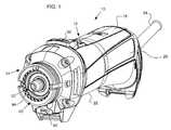
- FIG. 1is an isometric view taken from the front left of a rotary handheld power tool that incorporates an embodiment of the present invention
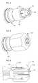
- FIG. 2is an isometric view of a right angle attachment device which also incorporates an embodiment of the present invention, with the attachment device being capable of being mounted to the power tool shown in FIG. 1 ;
- FIG. 3is a cross section taken through the center of the output shaft of the tool shown in FIG. 1 ;
- FIG. 4is an isometric view of a portion of the output shaft shown in FIG. 3 , having a collet inserted in the outer end thereof;
- FIG. 5is a view similar to FIG. 4 wherein a collet nut is attached to the output shaft;
- FIG. 6is a cross-section taken generally through the middle of the output shaft, collet and collet nut shown in FIG. 5 ;
- FIG. 7is a cross-section of a portion of the power tool shown in FIG. 1 , with the attachment device shown in FIG. 2 , with both being shown in cross section generally through the center thereof, but illustrating the attachment device in position where it is beginning to be mounted to the power tool;
- FIG. 8is a cross-section similar to FIG. 7 , but showing the attachment device attached thereto, and more particularly showing the attachment device mounted and secured to the power tool.
- the present inventionis directed to a drive system for releasably interconnecting an output shaft of a rotary handheld power tool or the like and an input shaft of an attachment device that is mounted on the power tool.
- a drive systemmay be particularly desirable for small handheld power tools having an elongated housing with a rotary output shaft is provided at a nose portion thereof, wherein the nose portion is configured to attach an attachment device thereto.
- an attachment devicemay be a right angle drive which has its own output shaft that may drive a circular saw blade, grinding wheel, or the like.
- the attachment devicehas an input shaft that must be interconnected with the output shaft of the power tool and it has been known that the interconnection of these two components can produce undesirable levels of vibration at relatively high operating speeds if there is misalignment of the shafts.
- Such vibrationcan be reduced by having the input shaft of the attachment device be made of a flexible material, which can be a multiplicity of parallel steel wires that are compressed under high pressure to form a shaft having a non-circular end, and preferably a square end, for engagement with the output shaft of a power tool, but which is sufficiently flexible that it can compensate for slight misalignment and significantly reduce vibration that would otherwise occur.
- Such flexible shaftsare known in the prior art.
- Embodiments of the drive system of the present inventiongreatly facilitate easy and fast mounting of an attachment device to such a power tool without interfering with a common use of the power tool where a collet and collet nut can be installed to attach standard tool bits to the output shaft, such as spiral saw bits and the like.
- an elongated power toolindicated generally at 10
- the housinghas an elongated housing, indicated generally at 12 , and a nose portion, indicated generally at 14 .
- the housinghas a top surface 18 , side surfaces 20 and a bottom surface 22 and a motor is contained within the housing.
- the size of the housing 12is such that most users can grip the tool with one hand with their fingers curling around under the bottom portion 22 .
- a switch 32which turns on the motor for operating the tool.
- the switch 32is preferably designed so that can be slidingly moved between its ON and OFF positions.
- FIG. 1has a power cord 34 that can be plugged into a source of AC power. It should be understood that power tools similar to that shown in FIG. 1 may incorporate battery packs and in such event, they may be slightly larger. The present invention is suited for use with power tools that use such power packs.
- the nose portion 14has an attachment interface that is described in a co-pending patent application entitled “AN ATTACHMENT INTERFACE FOR ROTARY HAND TOOLS”, Ser. No. 12/700,003 (U.S. Patent Application Publication No. 2011/0188957), that is filed concurrently with this application and is incorporated by reference herein.
- the nose portionwhich may be made of aluminum, has a cylindrical wall, indicated generally at 40 , which has outer threads 42 , as well as an inner surface that has a number of keys 44 that are configured to engage complementary shaped keys on an attachment device that may be mounted on the nose portion 14 .
- the tool 10has an output shaft, indicated generally at 50 , which is best shown in FIGS. 1 and 3 which is configured to be able to accept a collet and collet nut for mounting a cylindrical tool bit, such as spiral bit, for example, and is also configured to accept an input shaft of an attachment device that can be mounted on the nose portion 14 of the tool 10 .
- the output shaft 50which may be made of steel, is best shown in FIG. 3 and has a rearward (i.e., the left end) mounting portion, indicated generally at 52 , for attachment to a drive shaft of the motor of the power tool 10 , which is an armature shaft of the motor, an intermediate portion, indicated generally at 54 , that is configured to receive an input shaft (which may be made of steel) of the attachment device and a forward portion, indicated generally at 56 , that is configured to initially guide the input shaft of an attachment device into the intermediate portion 54 as well as interact with a collet and collet nut for mounting a tool bit to the output shaft 50 .
- the three portions, i.e., the mounting portion, intermediate portion and forward portionare approximately equal in length, although the proportions of each relative to the other may be varied as desired.
- the mounting portion 52has a central bore 60 that has a chamfered end surface 62 to facilitate entrance by the armature shaft 64 (see FIGS. 7 , 8 ) of the tool motor.
- the bore 60preferably is only slightly larger than the outer diameter of the armature shaft 64 , so that it is securely fastened therein after the mounting portion is compressed or crimped onto the shaft 64 .
- the mounting portion 52also has radial openings 66 , each with a chamfered outer surface 68 which is sized to receive a pin of a locking mechanism for locking the output shaft from rotation so that a tool bit can be firmly secured in a collet by tightening a collet nut.
- the mounting portion 52has the largest diameter of any of the portions 52 , 54 or 56 and the interface between the mounting portion 52 and the intermediate portion 54 defines an annular shoulder 72 .
- the intermediate portion 54has an outer surface 74 that has a diameter slightly larger than the outer surface 76 of the forward portion 56 so that a front bearing ( 104 , FIGS. 7 and 8 ) can be easily slipped on the forward end 56 without interference with the inside surface of the inner race of such a bearing and be mounted on the outer surface 74 of the intermediate portion 54 .
- the outer surface 74also has an annular groove 78 for receiving a retaining ring ( 112 , FIGS. 7 and 8 ) that holds the front bearing in place.
- the interface between the intermediate portion 54 and the forward portion 56defines another shoulder 80 and the smallest outside diameter of the entire output shaft 50 is surface 82 .
- the surface 76is slightly larger in diameter and it contains threads which are not shown but are well known to those of ordinary skill in the art for screwing or threading a collet nut onto the forward portion of the output shaft 50 .
- the bore 60 of the mounting portion 52is in communication with a cavity 84 that has a preferably square cross section.
- the cross sectional configuration of the cavity 84can be any non-circular shape that is complementary to the shaft that is inserted into it.
- This cavity 84has a length sufficient to hold a complementary shaped shaft ( 98 , FIGS. 7 and 8 ) that may be inserted into the forward end portion 56 .
- any noncircular type of cross sectionthat will enable rotation of the output shaft 50 to positively rotate a shaft that is located within it may be used.
- a five sided or hexagonal or other noncircular cross-sectional shapemay be used.
- a square cross-sectionis preferred because it does not require close tolerances between the size of the cavity 84 and the size of an input shaft that may be inserted in it.
- the forward end portion 56has an initial cylindrical bore portion 86 as well as a smaller step down portion 88 that in turn merges with an inclined conical portion 89 as well as a smaller diameter portion 91 that communicates with the cavity 84 .
- the progressively smaller inside diameters from the outer end extending inwardlyfacilitate easy initial insertion of an input shaft from an attachment device and effectively guides the same so that it can be inserted into the cavity 84 .
- An attachment deviceis indicated generally at 90 in FIG. 2 and comprises a right angle saw attachment device which can be mounted on the tool.
- the devicewill not be described in detail inasmuch as the present invention deals with only the interconnection of it with the tool on which it is mounted.
- the device 90has a main housing 92 and a rotatable collar 94 with internal threads 96 that are sized and configured to thread the collar 94 onto the threads 42 of the nose portion 14 of the powertool 10 .
- the device 90has an input shaft 98 which has a square outer end 100 that is sized and configured to fit within the cavity 84 .
- the input shaft 98is preferably permanently secured such as being crimped in a gear shaft in the attachment device 90 so that it will not be lost when the attachment device is separated from the power tool 10 .
- the length of the shaft 98is sufficiently long so that the outer square cross-section end portion 100 will penetrate the output shaft 50 so that it substantially fills the cavity 84 when the device is secured to the tool 10 .
- FIG. 7shows the device with the end portion 100 penetrating into the forward portion 56 of the output shaft 50 before the collar 94 is threaded or screwed onto threads 42 of the nose portion 14 as shown in FIG. 7 .
- the square end portion 100is fully inserted into the cavity 84 .
- FIGS. 7 and 8diagrammatically show a front bearing 104 with inner and outer races 106 and 108 with ball bearings 110 therebetween and a retaining clip 112 is located in the annular groove 78 . It is also noted that the mounting portion 52 is not completely shown in these drawings.
- the forward portion 56is configured to receive a collet and to this end, and referring to FIGS. 4 , 5 and 6 , a collet 120 is shown to fit within the bore 86 .
- the collet 120is only partially inserted in the bore 86 in FIG. 4 .
- a collet nut 122is configured to be threaded onto the threaded surface 76 .
- the collet nuthas an inclined inner surface 124 that interacts with an inclined outer surface 126 on the collet and another inclined surface 128 engages the surface 89 ( FIG. 3 ) of the forward portion 56 as is known to those of ordinary skill in the art.
- the collet nut 122is tightened, the internal diameter of the central opening is reduced to provide a holding force on a tool bit inserted in the collet 120 .
Landscapes
- Engineering & Computer Science (AREA)
- Mechanical Engineering (AREA)
- General Engineering & Computer Science (AREA)
- Health & Medical Sciences (AREA)
- Oral & Maxillofacial Surgery (AREA)
- Gripping On Spindles (AREA)
- Connection Of Motors, Electrical Generators, Mechanical Devices, And The Like (AREA)
Abstract
Description
Claims (14)
Priority Applications (1)
| Application Number | Priority Date | Filing Date | Title |
|---|---|---|---|
| US13/777,848US8893820B2 (en) | 2010-02-04 | 2013-02-26 | Drive system for interconnecting attachment devices and handheld rotary power tools |
Applications Claiming Priority (2)
| Application Number | Priority Date | Filing Date | Title |
|---|---|---|---|
| US12/700,338US8381834B2 (en) | 2010-02-04 | 2010-02-04 | Drive system for interconnecting attachment devices and handheld rotary power tools |
| US13/777,848US8893820B2 (en) | 2010-02-04 | 2013-02-26 | Drive system for interconnecting attachment devices and handheld rotary power tools |
Related Parent Applications (1)
| Application Number | Title | Priority Date | Filing Date |
|---|---|---|---|
| US12/700,338ContinuationUS8381834B2 (en) | 2010-02-04 | 2010-02-04 | Drive system for interconnecting attachment devices and handheld rotary power tools |
Publications (2)
| Publication Number | Publication Date |
|---|---|
| US20130168122A1 US20130168122A1 (en) | 2013-07-04 |
| US8893820B2true US8893820B2 (en) | 2014-11-25 |
Family
ID=44340634
Family Applications (2)
| Application Number | Title | Priority Date | Filing Date |
|---|---|---|---|
| US12/700,338Active2030-08-03US8381834B2 (en) | 2010-02-04 | 2010-02-04 | Drive system for interconnecting attachment devices and handheld rotary power tools |
| US13/777,848ActiveUS8893820B2 (en) | 2010-02-04 | 2013-02-26 | Drive system for interconnecting attachment devices and handheld rotary power tools |
Family Applications Before (1)
| Application Number | Title | Priority Date | Filing Date |
|---|---|---|---|
| US12/700,338Active2030-08-03US8381834B2 (en) | 2010-02-04 | 2010-02-04 | Drive system for interconnecting attachment devices and handheld rotary power tools |
Country Status (1)
| Country | Link |
|---|---|
| US (2) | US8381834B2 (en) |
Cited By (9)
| Publication number | Priority date | Publication date | Assignee | Title |
|---|---|---|---|---|
| USD782042S1 (en) | 2015-03-25 | 2017-03-21 | Medtronic Ps Medical, Inc. | Surgical tool |
| USD790699S1 (en) | 2015-03-25 | 2017-06-27 | Medtronic Ps Medical, Inc. | Surgical tool |
| USD800903S1 (en) | 2016-02-09 | 2017-10-24 | Medtronic Ps Medical, Inc. | Surgical tool |
| USD800907S1 (en) | 2015-03-25 | 2017-10-24 | Medtronic Ps Medical, Inc. | Surgical tool |
| USD800906S1 (en) | 2015-03-25 | 2017-10-24 | Medtronic Ps Medical, Inc. | Surgical tool |
| US10080579B2 (en) | 2015-03-25 | 2018-09-25 | Medtronic Ps Medical, Inc. | Pin drive rotary surgical cutting tools and powered handpieces |
| US10314610B2 (en) | 2015-03-25 | 2019-06-11 | Medtronic Ps Medical, Inc. | Slanted drive axis rotary surgical cutting tools and powered handpieces |
| US10849634B2 (en) | 2018-06-20 | 2020-12-01 | Medtronic Xomed, Inc. | Coupling portion for rotary surgical cutting systems |
| US12440902B2 (en) | 2024-01-08 | 2025-10-14 | Medtronic Ps Medical, Inc. | Pin drive rotary surgical cutting tools and powered handpieces |
Families Citing this family (160)
| Publication number | Priority date | Publication date | Assignee | Title |
|---|---|---|---|---|
| US20070084897A1 (en) | 2003-05-20 | 2007-04-19 | Shelton Frederick E Iv | Articulating surgical stapling instrument incorporating a two-piece e-beam firing mechanism |
| US9060770B2 (en) | 2003-05-20 | 2015-06-23 | Ethicon Endo-Surgery, Inc. | Robotically-driven surgical instrument with E-beam driver |
| US11890012B2 (en) | 2004-07-28 | 2024-02-06 | Cilag Gmbh International | Staple cartridge comprising cartridge body and attached support |
| US11998198B2 (en) | 2004-07-28 | 2024-06-04 | Cilag Gmbh International | Surgical stapling instrument incorporating a two-piece E-beam firing mechanism |
| US9072535B2 (en) | 2011-05-27 | 2015-07-07 | Ethicon Endo-Surgery, Inc. | Surgical stapling instruments with rotatable staple deployment arrangements |
| US10159482B2 (en) | 2005-08-31 | 2018-12-25 | Ethicon Llc | Fastener cartridge assembly comprising a fixed anvil and different staple heights |
| US11246590B2 (en) | 2005-08-31 | 2022-02-15 | Cilag Gmbh International | Staple cartridge including staple drivers having different unfired heights |
| US7669746B2 (en) | 2005-08-31 | 2010-03-02 | Ethicon Endo-Surgery, Inc. | Staple cartridges for forming staples having differing formed staple heights |
| US8708213B2 (en) | 2006-01-31 | 2014-04-29 | Ethicon Endo-Surgery, Inc. | Surgical instrument having a feedback system |
| US11793518B2 (en) | 2006-01-31 | 2023-10-24 | Cilag Gmbh International | Powered surgical instruments with firing system lockout arrangements |
| US20120292367A1 (en) | 2006-01-31 | 2012-11-22 | Ethicon Endo-Surgery, Inc. | Robotically-controlled end effector |
| US7845537B2 (en) | 2006-01-31 | 2010-12-07 | Ethicon Endo-Surgery, Inc. | Surgical instrument having recording capabilities |
| US8186555B2 (en) | 2006-01-31 | 2012-05-29 | Ethicon Endo-Surgery, Inc. | Motor-driven surgical cutting and fastening instrument with mechanical closure system |
| US8992422B2 (en) | 2006-03-23 | 2015-03-31 | Ethicon Endo-Surgery, Inc. | Robotically-controlled endoscopic accessory channel |
| US11980366B2 (en) | 2006-10-03 | 2024-05-14 | Cilag Gmbh International | Surgical instrument |
| US8684253B2 (en) | 2007-01-10 | 2014-04-01 | Ethicon Endo-Surgery, Inc. | Surgical instrument with wireless communication between a control unit of a robotic system and remote sensor |
| US8632535B2 (en) | 2007-01-10 | 2014-01-21 | Ethicon Endo-Surgery, Inc. | Interlock and surgical instrument including same |
| US20080169333A1 (en) | 2007-01-11 | 2008-07-17 | Shelton Frederick E | Surgical stapler end effector with tapered distal end |
| US8931682B2 (en) | 2007-06-04 | 2015-01-13 | Ethicon Endo-Surgery, Inc. | Robotically-controlled shaft based rotary drive systems for surgical instruments |
| US11564682B2 (en) | 2007-06-04 | 2023-01-31 | Cilag Gmbh International | Surgical stapler device |
| US11849941B2 (en) | 2007-06-29 | 2023-12-26 | Cilag Gmbh International | Staple cartridge having staple cavities extending at a transverse angle relative to a longitudinal cartridge axis |
| US8573465B2 (en) | 2008-02-14 | 2013-11-05 | Ethicon Endo-Surgery, Inc. | Robotically-controlled surgical end effector system with rotary actuated closure systems |
| JP5410110B2 (en) | 2008-02-14 | 2014-02-05 | エシコン・エンド−サージェリィ・インコーポレイテッド | Surgical cutting / fixing instrument with RF electrode |
| US8636736B2 (en) | 2008-02-14 | 2014-01-28 | Ethicon Endo-Surgery, Inc. | Motorized surgical cutting and fastening instrument |
| US11986183B2 (en) | 2008-02-14 | 2024-05-21 | Cilag Gmbh International | Surgical cutting and fastening instrument comprising a plurality of sensors to measure an electrical parameter |
| US9585657B2 (en) | 2008-02-15 | 2017-03-07 | Ethicon Endo-Surgery, Llc | Actuator for releasing a layer of material from a surgical end effector |
| US8210411B2 (en) | 2008-09-23 | 2012-07-03 | Ethicon Endo-Surgery, Inc. | Motor-driven surgical cutting instrument |
| US9005230B2 (en) | 2008-09-23 | 2015-04-14 | Ethicon Endo-Surgery, Inc. | Motorized surgical instrument |
| US9386983B2 (en) | 2008-09-23 | 2016-07-12 | Ethicon Endo-Surgery, Llc | Robotically-controlled motorized surgical instrument |
| US8608045B2 (en) | 2008-10-10 | 2013-12-17 | Ethicon Endo-Sugery, Inc. | Powered surgical cutting and stapling apparatus with manually retractable firing system |
| US12213666B2 (en) | 2010-09-30 | 2025-02-04 | Cilag Gmbh International | Tissue thickness compensator comprising layers |
| US10945731B2 (en) | 2010-09-30 | 2021-03-16 | Ethicon Llc | Tissue thickness compensator comprising controlled release and expansion |
| US11925354B2 (en) | 2010-09-30 | 2024-03-12 | Cilag Gmbh International | Staple cartridge comprising staples positioned within a compressible portion thereof |
| US9386988B2 (en) | 2010-09-30 | 2016-07-12 | Ethicon End-Surgery, LLC | Retainer assembly including a tissue thickness compensator |
| US9788834B2 (en) | 2010-09-30 | 2017-10-17 | Ethicon Llc | Layer comprising deployable attachment members |
| US9629814B2 (en) | 2010-09-30 | 2017-04-25 | Ethicon Endo-Surgery, Llc | Tissue thickness compensator configured to redistribute compressive forces |
| US11812965B2 (en) | 2010-09-30 | 2023-11-14 | Cilag Gmbh International | Layer of material for a surgical end effector |
| CN106217295B (en)* | 2011-03-11 | 2019-07-12 | S·D·温纳德 | Hand-held drive device |
| US9566692B2 (en)* | 2011-04-05 | 2017-02-14 | Ingersoll-Rand Company | Rotary impact device |
| US10427277B2 (en) | 2011-04-05 | 2019-10-01 | Ingersoll-Rand Company | Impact wrench having dynamically tuned drive components and method thereof |
| US9463557B2 (en) | 2014-01-31 | 2016-10-11 | Ingersoll-Rand Company | Power socket for an impact tool |
| AU2012250197B2 (en) | 2011-04-29 | 2017-08-10 | Ethicon Endo-Surgery, Inc. | Staple cartridge comprising staples positioned within a compressible portion thereof |
| US11207064B2 (en) | 2011-05-27 | 2021-12-28 | Cilag Gmbh International | Automated end effector component reloading system for use with a robotic system |
| SE535919C2 (en)* | 2011-06-30 | 2013-02-19 | Atlas Copco Ind Tech Ab | Electrically powered tool |
| MX358135B (en) | 2012-03-28 | 2018-08-06 | Ethicon Endo Surgery Inc | Tissue thickness compensator comprising a plurality of layers. |
| BR112014024098B1 (en) | 2012-03-28 | 2021-05-25 | Ethicon Endo-Surgery, Inc. | staple cartridge |
| JP2013208678A (en)* | 2012-03-30 | 2013-10-10 | Hitachi Koki Co Ltd | Impact tool |
| US9101358B2 (en) | 2012-06-15 | 2015-08-11 | Ethicon Endo-Surgery, Inc. | Articulatable surgical instrument comprising a firing drive |
| US20140001231A1 (en) | 2012-06-28 | 2014-01-02 | Ethicon Endo-Surgery, Inc. | Firing system lockout arrangements for surgical instruments |
| US9289256B2 (en) | 2012-06-28 | 2016-03-22 | Ethicon Endo-Surgery, Llc | Surgical end effectors having angled tissue-contacting surfaces |
| US12383267B2 (en) | 2012-06-28 | 2025-08-12 | Cilag Gmbh International | Robotically powered surgical device with manually-actuatable reversing system |
| USD694606S1 (en)* | 2012-08-22 | 2013-12-03 | Robert Bosch Gmbh | Right angle attachment for a rotary hand tool |
| BR112015021082B1 (en) | 2013-03-01 | 2022-05-10 | Ethicon Endo-Surgery, Inc | surgical instrument |
| RU2672520C2 (en) | 2013-03-01 | 2018-11-15 | Этикон Эндо-Серджери, Инк. | Hingedly turnable surgical instruments with conducting ways for signal transfer |
| US9629629B2 (en) | 2013-03-14 | 2017-04-25 | Ethicon Endo-Surgey, LLC | Control systems for surgical instruments |
| BR112015026109B1 (en) | 2013-04-16 | 2022-02-22 | Ethicon Endo-Surgery, Inc | surgical instrument |
| US9775609B2 (en) | 2013-08-23 | 2017-10-03 | Ethicon Llc | Tamper proof circuit for surgical instrument battery pack |
| CN103590767A (en)* | 2013-11-16 | 2014-02-19 | 无锡中地地质装备有限公司 | Front handle structure of pipe twisting machine shell body |
| FR3018712B1 (en)* | 2014-03-20 | 2016-12-30 | Arts | DRILLING TOOL WITH TWO COAXIAL ENGINES |
| US10013049B2 (en) | 2014-03-26 | 2018-07-03 | Ethicon Llc | Power management through sleep options of segmented circuit and wake up control |
| US12232723B2 (en) | 2014-03-26 | 2025-02-25 | Cilag Gmbh International | Systems and methods for controlling a segmented circuit |
| US20150272580A1 (en) | 2014-03-26 | 2015-10-01 | Ethicon Endo-Surgery, Inc. | Verification of number of battery exchanges/procedure count |
| CN106456159B (en) | 2014-04-16 | 2019-03-08 | 伊西康内外科有限责任公司 | Fastener Cartridge Assembly and Nail Retainer Cover Arrangement |
| US20150297225A1 (en) | 2014-04-16 | 2015-10-22 | Ethicon Endo-Surgery, Inc. | Fastener cartridges including extensions having different configurations |
| US10327764B2 (en) | 2014-09-26 | 2019-06-25 | Ethicon Llc | Method for creating a flexible staple line |
| BR112016023825B1 (en) | 2014-04-16 | 2022-08-02 | Ethicon Endo-Surgery, Llc | STAPLE CARTRIDGE FOR USE WITH A SURGICAL STAPLER AND STAPLE CARTRIDGE FOR USE WITH A SURGICAL INSTRUMENT |
| CN106456176B (en) | 2014-04-16 | 2019-06-28 | 伊西康内外科有限责任公司 | Fastener Cartridge Including Extensions With Different Configurations |
| US9751176B2 (en) | 2014-05-30 | 2017-09-05 | Black & Decker Inc. | Power tool accessory attachment system |
| BR112017004361B1 (en) | 2014-09-05 | 2023-04-11 | Ethicon Llc | ELECTRONIC SYSTEM FOR A SURGICAL INSTRUMENT |
| US11311294B2 (en) | 2014-09-05 | 2022-04-26 | Cilag Gmbh International | Powered medical device including measurement of closure state of jaws |
| US10105142B2 (en) | 2014-09-18 | 2018-10-23 | Ethicon Llc | Surgical stapler with plurality of cutting elements |
| US11523821B2 (en) | 2014-09-26 | 2022-12-13 | Cilag Gmbh International | Method for creating a flexible staple line |
| US9924944B2 (en) | 2014-10-16 | 2018-03-27 | Ethicon Llc | Staple cartridge comprising an adjunct material |
| US10736636B2 (en) | 2014-12-10 | 2020-08-11 | Ethicon Llc | Articulatable surgical instrument system |
| US10399214B2 (en) | 2014-12-17 | 2019-09-03 | Stanley D. Winnard | Ratchet wrench |
| US9987000B2 (en) | 2014-12-18 | 2018-06-05 | Ethicon Llc | Surgical instrument assembly comprising a flexible articulation system |
| US11154301B2 (en) | 2015-02-27 | 2021-10-26 | Cilag Gmbh International | Modular stapling assembly |
| US10441279B2 (en) | 2015-03-06 | 2019-10-15 | Ethicon Llc | Multiple level thresholds to modify operation of powered surgical instruments |
| US10433844B2 (en) | 2015-03-31 | 2019-10-08 | Ethicon Llc | Surgical instrument with selectively disengageable threaded drive systems |
| US10697250B2 (en)* | 2015-04-02 | 2020-06-30 | Sandvik Intellectual Property Ab | Multi-functional connector, drill head, and method |
| US10105139B2 (en) | 2015-09-23 | 2018-10-23 | Ethicon Llc | Surgical stapler having downstream current-based motor control |
| US10299878B2 (en) | 2015-09-25 | 2019-05-28 | Ethicon Llc | Implantable adjunct systems for determining adjunct skew |
| US10433846B2 (en) | 2015-09-30 | 2019-10-08 | Ethicon Llc | Compressible adjunct with crossing spacer fibers |
| US10478188B2 (en) | 2015-09-30 | 2019-11-19 | Ethicon Llc | Implantable layer comprising a constricted configuration |
| US11890015B2 (en) | 2015-09-30 | 2024-02-06 | Cilag Gmbh International | Compressible adjunct with crossing spacer fibers |
| US10292704B2 (en) | 2015-12-30 | 2019-05-21 | Ethicon Llc | Mechanisms for compensating for battery pack failure in powered surgical instruments |
| US10265068B2 (en) | 2015-12-30 | 2019-04-23 | Ethicon Llc | Surgical instruments with separable motors and motor control circuits |
| US11213293B2 (en) | 2016-02-09 | 2022-01-04 | Cilag Gmbh International | Articulatable surgical instruments with single articulation link arrangements |
| US10448948B2 (en) | 2016-02-12 | 2019-10-22 | Ethicon Llc | Mechanisms for compensating for drivetrain failure in powered surgical instruments |
| US10357247B2 (en) | 2016-04-15 | 2019-07-23 | Ethicon Llc | Surgical instrument with multiple program responses during a firing motion |
| US10828028B2 (en) | 2016-04-15 | 2020-11-10 | Ethicon Llc | Surgical instrument with multiple program responses during a firing motion |
| US20170296173A1 (en) | 2016-04-18 | 2017-10-19 | Ethicon Endo-Surgery, Llc | Method for operating a surgical instrument |
| US10500000B2 (en) | 2016-08-16 | 2019-12-10 | Ethicon Llc | Surgical tool with manual control of end effector jaws |
| US10973516B2 (en) | 2016-12-21 | 2021-04-13 | Ethicon Llc | Surgical end effectors and adaptable firing members therefor |
| US20180168625A1 (en) | 2016-12-21 | 2018-06-21 | Ethicon Endo-Surgery, Llc | Surgical stapling instruments with smart staple cartridges |
| JP7010956B2 (en) | 2016-12-21 | 2022-01-26 | エシコン エルエルシー | How to staple tissue |
| US10813638B2 (en) | 2016-12-21 | 2020-10-27 | Ethicon Llc | Surgical end effectors with expandable tissue stop arrangements |
| JP7010957B2 (en) | 2016-12-21 | 2022-01-26 | エシコン エルエルシー | Shaft assembly with lockout |
| US10307170B2 (en) | 2017-06-20 | 2019-06-04 | Ethicon Llc | Method for closed loop control of motor velocity of a surgical stapling and cutting instrument |
| US10779820B2 (en) | 2017-06-20 | 2020-09-22 | Ethicon Llc | Systems and methods for controlling motor speed according to user input for a surgical instrument |
| US11484310B2 (en) | 2017-06-28 | 2022-11-01 | Cilag Gmbh International | Surgical instrument comprising a shaft including a closure tube profile |
| USD906355S1 (en) | 2017-06-28 | 2020-12-29 | Ethicon Llc | Display screen or portion thereof with a graphical user interface for a surgical instrument |
| EP3420947B1 (en) | 2017-06-28 | 2022-05-25 | Cilag GmbH International | Surgical instrument comprising selectively actuatable rotatable couplers |
| US10932772B2 (en) | 2017-06-29 | 2021-03-02 | Ethicon Llc | Methods for closed loop velocity control for robotic surgical instrument |
| US11974742B2 (en) | 2017-08-03 | 2024-05-07 | Cilag Gmbh International | Surgical system comprising an articulation bailout |
| US11134944B2 (en) | 2017-10-30 | 2021-10-05 | Cilag Gmbh International | Surgical stapler knife motion controls |
| US10842490B2 (en) | 2017-10-31 | 2020-11-24 | Ethicon Llc | Cartridge body design with force reduction based on firing completion |
| US10779826B2 (en) | 2017-12-15 | 2020-09-22 | Ethicon Llc | Methods of operating surgical end effectors |
| US10835330B2 (en) | 2017-12-19 | 2020-11-17 | Ethicon Llc | Method for determining the position of a rotatable jaw of a surgical instrument attachment assembly |
| US12336705B2 (en) | 2017-12-21 | 2025-06-24 | Cilag Gmbh International | Continuous use self-propelled stapling instrument |
| US11179151B2 (en) | 2017-12-21 | 2021-11-23 | Cilag Gmbh International | Surgical instrument comprising a display |
| US20200054321A1 (en) | 2018-08-20 | 2020-02-20 | Ethicon Llc | Surgical instruments with progressive jaw closure arrangements |
| US11207065B2 (en) | 2018-08-20 | 2021-12-28 | Cilag Gmbh International | Method for fabricating surgical stapler anvils |
| US11291440B2 (en) | 2018-08-20 | 2022-04-05 | Cilag Gmbh International | Method for operating a powered articulatable surgical instrument |
| US20200345359A1 (en) | 2019-04-30 | 2020-11-05 | Ethicon Llc | Tissue stop for a surgical instrument |
| US11903581B2 (en) | 2019-04-30 | 2024-02-20 | Cilag Gmbh International | Methods for stapling tissue using a surgical instrument |
| US11771419B2 (en) | 2019-06-28 | 2023-10-03 | Cilag Gmbh International | Packaging for a replaceable component of a surgical stapling system |
| US11241235B2 (en) | 2019-06-28 | 2022-02-08 | Cilag Gmbh International | Method of using multiple RFID chips with a surgical assembly |
| US11701111B2 (en) | 2019-12-19 | 2023-07-18 | Cilag Gmbh International | Method for operating a surgical stapling instrument |
| US12035913B2 (en) | 2019-12-19 | 2024-07-16 | Cilag Gmbh International | Staple cartridge comprising a deployable knife |
| CN212683073U (en)* | 2020-05-07 | 2021-03-12 | 阿特拉斯·科普柯工业技术公司 | A batch head connecting device and a tightening module |
| US11779330B2 (en) | 2020-10-29 | 2023-10-10 | Cilag Gmbh International | Surgical instrument comprising a jaw alignment system |
| US11896217B2 (en) | 2020-10-29 | 2024-02-13 | Cilag Gmbh International | Surgical instrument comprising an articulation lock |
| US11931025B2 (en) | 2020-10-29 | 2024-03-19 | Cilag Gmbh International | Surgical instrument comprising a releasable closure drive lock |
| USD1013170S1 (en) | 2020-10-29 | 2024-01-30 | Cilag Gmbh International | Surgical instrument assembly |
| US12053175B2 (en) | 2020-10-29 | 2024-08-06 | Cilag Gmbh International | Surgical instrument comprising a stowed closure actuator stop |
| US11944296B2 (en) | 2020-12-02 | 2024-04-02 | Cilag Gmbh International | Powered surgical instruments with external connectors |
| US11737751B2 (en) | 2020-12-02 | 2023-08-29 | Cilag Gmbh International | Devices and methods of managing energy dissipated within sterile barriers of surgical instrument housings |
| US11849943B2 (en) | 2020-12-02 | 2023-12-26 | Cilag Gmbh International | Surgical instrument with cartridge release mechanisms |
| US11744581B2 (en) | 2020-12-02 | 2023-09-05 | Cilag Gmbh International | Powered surgical instruments with multi-phase tissue treatment |
| US11812964B2 (en) | 2021-02-26 | 2023-11-14 | Cilag Gmbh International | Staple cartridge comprising a power management circuit |
| US11730473B2 (en) | 2021-02-26 | 2023-08-22 | Cilag Gmbh International | Monitoring of manufacturing life-cycle |
| US11744583B2 (en) | 2021-02-26 | 2023-09-05 | Cilag Gmbh International | Distal communication array to tune frequency of RF systems |
| US12108951B2 (en) | 2021-02-26 | 2024-10-08 | Cilag Gmbh International | Staple cartridge comprising a sensing array and a temperature control system |
| US11749877B2 (en) | 2021-02-26 | 2023-09-05 | Cilag Gmbh International | Stapling instrument comprising a signal antenna |
| US11751869B2 (en) | 2021-02-26 | 2023-09-12 | Cilag Gmbh International | Monitoring of multiple sensors over time to detect moving characteristics of tissue |
| US11980362B2 (en) | 2021-02-26 | 2024-05-14 | Cilag Gmbh International | Surgical instrument system comprising a power transfer coil |
| US11950777B2 (en) | 2021-02-26 | 2024-04-09 | Cilag Gmbh International | Staple cartridge comprising an information access control system |
| US11723657B2 (en) | 2021-02-26 | 2023-08-15 | Cilag Gmbh International | Adjustable communication based on available bandwidth and power capacity |
| US12324580B2 (en) | 2021-02-26 | 2025-06-10 | Cilag Gmbh International | Method of powering and communicating with a staple cartridge |
| USD974869S1 (en)* | 2021-03-08 | 2023-01-10 | Photonix Corp | Cutting tool |
| US11826042B2 (en) | 2021-03-22 | 2023-11-28 | Cilag Gmbh International | Surgical instrument comprising a firing drive including a selectable leverage mechanism |
| US11806011B2 (en) | 2021-03-22 | 2023-11-07 | Cilag Gmbh International | Stapling instrument comprising tissue compression systems |
| US11759202B2 (en) | 2021-03-22 | 2023-09-19 | Cilag Gmbh International | Staple cartridge comprising an implantable layer |
| US11723658B2 (en) | 2021-03-22 | 2023-08-15 | Cilag Gmbh International | Staple cartridge comprising a firing lockout |
| US11826012B2 (en) | 2021-03-22 | 2023-11-28 | Cilag Gmbh International | Stapling instrument comprising a pulsed motor-driven firing rack |
| US11717291B2 (en) | 2021-03-22 | 2023-08-08 | Cilag Gmbh International | Staple cartridge comprising staples configured to apply different tissue compression |
| US11737749B2 (en) | 2021-03-22 | 2023-08-29 | Cilag Gmbh International | Surgical stapling instrument comprising a retraction system |
| US11896218B2 (en) | 2021-03-24 | 2024-02-13 | Cilag Gmbh International | Method of using a powered stapling device |
| US11896219B2 (en) | 2021-03-24 | 2024-02-13 | Cilag Gmbh International | Mating features between drivers and underside of a cartridge deck |
| US11849945B2 (en) | 2021-03-24 | 2023-12-26 | Cilag Gmbh International | Rotary-driven surgical stapling assembly comprising eccentrically driven firing member |
| US11744603B2 (en) | 2021-03-24 | 2023-09-05 | Cilag Gmbh International | Multi-axis pivot joints for surgical instruments and methods for manufacturing same |
| US11826047B2 (en) | 2021-05-28 | 2023-11-28 | Cilag Gmbh International | Stapling instrument comprising jaw mounts |
| US11980363B2 (en) | 2021-10-18 | 2024-05-14 | Cilag Gmbh International | Row-to-row staple array variations |
| US12089841B2 (en) | 2021-10-28 | 2024-09-17 | Cilag CmbH International | Staple cartridge identification systems |
| US12432790B2 (en) | 2021-10-28 | 2025-09-30 | Cilag Gmbh International | Method and device for transmitting UART communications over a security short range wireless communication |
| US11937816B2 (en) | 2021-10-28 | 2024-03-26 | Cilag Gmbh International | Electrical lead arrangements for surgical instruments |
| KR102419812B1 (en)* | 2021-11-17 | 2022-07-12 | (주)볼팅마스타 | Coupling device for replacement of gear box of electric torque wrench |
| US20230234202A1 (en)* | 2022-01-27 | 2023-07-27 | Shukla Medical | Power adapter for a powered tool |
| US20230302620A1 (en)* | 2022-03-28 | 2023-09-28 | Milwaukee Electric Tool Corporation | Rotary power tool |
Citations (19)
| Publication number | Priority date | Publication date | Assignee | Title |
|---|---|---|---|---|
| US2618940A (en)* | 1948-06-25 | 1952-11-25 | Wyzenbeek Andrew | Flexible shaft handpiece coupling |
| US3505831A (en)* | 1968-07-05 | 1970-04-14 | Skil Corp | Flexible shaft coupler |
| US3724561A (en)* | 1971-09-09 | 1973-04-03 | F Merrels | Multiple tool driving unit |
| US3759336A (en)* | 1972-01-21 | 1973-09-18 | D Marcovitz | Interchangeable power operated tools |
| US4541160A (en)* | 1981-02-23 | 1985-09-17 | Roberts Thomas C | Process of using a flexible shaft motor coupling having interchangeable adaptors |
| US4949463A (en)* | 1988-11-28 | 1990-08-21 | Chen Yi Chang | Sawing device attachable to regular electric drill |
| US4989323A (en)* | 1989-06-05 | 1991-02-05 | Caspro Mechanical Technologies, Inc. | Portable power unit for various power tolls |
| US5626474A (en)* | 1995-06-28 | 1997-05-06 | Kukla; Thomas S. | Implant torque wrench |
| US5863159A (en)* | 1997-12-12 | 1999-01-26 | Lasko; Leonard J. | Drill angle attachment coupling |
| US6035515A (en)* | 1998-10-16 | 2000-03-14 | Shopvac Corporation | Motor shaft assembly and method |
| US6463824B1 (en)* | 2000-02-29 | 2002-10-15 | S-B Power Tool Company | Right angle attachment for power hand tool |
| US6508475B1 (en)* | 2001-10-31 | 2003-01-21 | Hudson Precision Products Co. | Holding apparatus with improved retention ability and method of holding a tool |
| US6712368B2 (en)* | 2001-11-08 | 2004-03-30 | S-B Power Tool Company | Quick attachment release system for a rotary hand tool |
| EP1454710A1 (en) | 2003-03-03 | 2004-09-08 | Credo Technology Corporation | Angle attachment for power tool |
| US6790144B2 (en)* | 2002-04-12 | 2004-09-14 | Credo Technology Corporation | Flexible shaft plug insert |
| US7004668B2 (en)* | 2002-10-16 | 2006-02-28 | Mtd Products Inc | Connector for flex shaft for string trimmer |
| US7052382B2 (en) | 2003-08-26 | 2006-05-30 | Credo Technology Corporation | Accessory attachment for rotary hand tools |
| WO2008013680A1 (en) | 2006-07-27 | 2008-01-31 | Robert Bosch Gmbh | Cutting attachment with a removable cover for rotary hand tools |
| US20110186322A1 (en)* | 2010-02-04 | 2011-08-04 | Credo Technology Corporation | lockout apparatus for protecting an attachment device mounted on rotary power tools |
- 2010
- 2010-02-04USUS12/700,338patent/US8381834B2/enactiveActive
- 2013
- 2013-02-26USUS13/777,848patent/US8893820B2/enactiveActive
Patent Citations (21)
| Publication number | Priority date | Publication date | Assignee | Title |
|---|---|---|---|---|
| US2618940A (en)* | 1948-06-25 | 1952-11-25 | Wyzenbeek Andrew | Flexible shaft handpiece coupling |
| US3505831A (en)* | 1968-07-05 | 1970-04-14 | Skil Corp | Flexible shaft coupler |
| US3724561A (en)* | 1971-09-09 | 1973-04-03 | F Merrels | Multiple tool driving unit |
| US3759336A (en)* | 1972-01-21 | 1973-09-18 | D Marcovitz | Interchangeable power operated tools |
| US4541160A (en)* | 1981-02-23 | 1985-09-17 | Roberts Thomas C | Process of using a flexible shaft motor coupling having interchangeable adaptors |
| US4949463A (en)* | 1988-11-28 | 1990-08-21 | Chen Yi Chang | Sawing device attachable to regular electric drill |
| US4989323A (en)* | 1989-06-05 | 1991-02-05 | Caspro Mechanical Technologies, Inc. | Portable power unit for various power tolls |
| US5626474A (en)* | 1995-06-28 | 1997-05-06 | Kukla; Thomas S. | Implant torque wrench |
| US5863159A (en)* | 1997-12-12 | 1999-01-26 | Lasko; Leonard J. | Drill angle attachment coupling |
| US7241117B2 (en)* | 1998-10-16 | 2007-07-10 | Shop Vac Corporation | Motor shaft assembly and method |
| US6035515A (en)* | 1998-10-16 | 2000-03-14 | Shopvac Corporation | Motor shaft assembly and method |
| US6463824B1 (en)* | 2000-02-29 | 2002-10-15 | S-B Power Tool Company | Right angle attachment for power hand tool |
| US6508475B1 (en)* | 2001-10-31 | 2003-01-21 | Hudson Precision Products Co. | Holding apparatus with improved retention ability and method of holding a tool |
| US6712368B2 (en)* | 2001-11-08 | 2004-03-30 | S-B Power Tool Company | Quick attachment release system for a rotary hand tool |
| US6790144B2 (en)* | 2002-04-12 | 2004-09-14 | Credo Technology Corporation | Flexible shaft plug insert |
| US7004668B2 (en)* | 2002-10-16 | 2006-02-28 | Mtd Products Inc | Connector for flex shaft for string trimmer |
| EP1454710A1 (en) | 2003-03-03 | 2004-09-08 | Credo Technology Corporation | Angle attachment for power tool |
| US7077736B2 (en)* | 2003-03-03 | 2006-07-18 | Credo Technology Corporation | Angle attachment for power tool |
| US7052382B2 (en) | 2003-08-26 | 2006-05-30 | Credo Technology Corporation | Accessory attachment for rotary hand tools |
| WO2008013680A1 (en) | 2006-07-27 | 2008-01-31 | Robert Bosch Gmbh | Cutting attachment with a removable cover for rotary hand tools |
| US20110186322A1 (en)* | 2010-02-04 | 2011-08-04 | Credo Technology Corporation | lockout apparatus for protecting an attachment device mounted on rotary power tools |
Cited By (13)
| Publication number | Priority date | Publication date | Assignee | Title |
|---|---|---|---|---|
| US10314610B2 (en) | 2015-03-25 | 2019-06-11 | Medtronic Ps Medical, Inc. | Slanted drive axis rotary surgical cutting tools and powered handpieces |
| USD790699S1 (en) | 2015-03-25 | 2017-06-27 | Medtronic Ps Medical, Inc. | Surgical tool |
| USD800907S1 (en) | 2015-03-25 | 2017-10-24 | Medtronic Ps Medical, Inc. | Surgical tool |
| USD800906S1 (en) | 2015-03-25 | 2017-10-24 | Medtronic Ps Medical, Inc. | Surgical tool |
| US10080579B2 (en) | 2015-03-25 | 2018-09-25 | Medtronic Ps Medical, Inc. | Pin drive rotary surgical cutting tools and powered handpieces |
| USD782042S1 (en) | 2015-03-25 | 2017-03-21 | Medtronic Ps Medical, Inc. | Surgical tool |
| US10905453B2 (en) | 2015-03-25 | 2021-02-02 | Medtronic Ps Medical, Inc. | Pin drive rotary surgical cutting tools and powered handpieces |
| US11154319B2 (en) | 2015-03-25 | 2021-10-26 | Medtronic Ps Medical, Inc. | Slanted drive axis rotary surgical cutting tools and powered handpieces |
| US11864784B2 (en) | 2015-03-25 | 2024-01-09 | Medtronic Ps Medical, Inc. | Pin drive rotary surgical cutting tools and powered handpieces |
| USD800903S1 (en) | 2016-02-09 | 2017-10-24 | Medtronic Ps Medical, Inc. | Surgical tool |
| US10849634B2 (en) | 2018-06-20 | 2020-12-01 | Medtronic Xomed, Inc. | Coupling portion for rotary surgical cutting systems |
| US12137918B2 (en) | 2018-06-20 | 2024-11-12 | Medtronic Xomed, Inc. | Coupling portion for rotary surgical cutting systems |
| US12440902B2 (en) | 2024-01-08 | 2025-10-14 | Medtronic Ps Medical, Inc. | Pin drive rotary surgical cutting tools and powered handpieces |
Also Published As
| Publication number | Publication date |
|---|---|
| US8381834B2 (en) | 2013-02-26 |
| US20130168122A1 (en) | 2013-07-04 |
| US20110186316A1 (en) | 2011-08-04 |
Similar Documents
| Publication | Publication Date | Title |
|---|---|---|
| US8893820B2 (en) | Drive system for interconnecting attachment devices and handheld rotary power tools | |
| US8061718B2 (en) | Toolless bitholder for spiral saws | |
| US6463824B1 (en) | Right angle attachment for power hand tool | |
| US7997169B1 (en) | Housed extension bar | |
| US20050047878A1 (en) | Tool chuck having a light transmitting capability | |
| US20110110734A1 (en) | Power tool configured for supporting a removable attachment | |
| US20230072364A1 (en) | Socket apparatus | |
| JP3108654B2 (en) | Keyless drill chuck | |
| US10513023B2 (en) | Power tool | |
| EP1688221B1 (en) | Manually driven hand tool with side handle | |
| US8753048B2 (en) | Hole saw | |
| EP2777847B1 (en) | Power tool | |
| US6913429B1 (en) | Tooless bit retaining assembly | |
| US8327551B2 (en) | Attachment interface for rotary hand tools | |
| US6712368B2 (en) | Quick attachment release system for a rotary hand tool | |
| US7722300B1 (en) | Chuck with internal geared tightening mechanism | |
| US8312936B2 (en) | Lockout apparatus for protecting an attachment device mounted on rotary power tools | |
| US8381832B1 (en) | Combination drywall screw gun and rotary saw device | |
| US20050025588A1 (en) | Handpiece apparatus used for cutting tools | |
| CN2936609Y (en) | Electric tool secondary handle | |
| US8888420B2 (en) | Tool chucking apparatus | |
| EP4375015A1 (en) | Device for supporting bits for a tool | |
| CN101513732B (en) | Drive extensions for power tools | |
| US20030178795A1 (en) | Keyless chuck with backup key operation | |
| CN108081215B (en) | Manual drilling, sawing and twisting integrated machine |
Legal Events
| Date | Code | Title | Description |
|---|---|---|---|
| AS | Assignment | Owner name:ROBERT BOSCH GMBH, GERMANY Free format text:ASSIGNMENT OF ASSIGNORS INTEREST;ASSIGNORS:BARHITTE, JOSH;ABURTO, HIRAM;CANDIA, ERNESTO;AND OTHERS;SIGNING DATES FROM 20100305 TO 20100524;REEL/FRAME:030742/0343 Owner name:ROBERT BOSCH TOOL CORPORATION, ILLINOIS Free format text:ASSIGNMENT OF ASSIGNORS INTEREST;ASSIGNORS:BARHITTE, JOSH;ABURTO, HIRAM;CANDIA, ERNESTO;AND OTHERS;SIGNING DATES FROM 20100305 TO 20100524;REEL/FRAME:030742/0343 | |
| STCF | Information on status: patent grant | Free format text:PATENTED CASE | |
| MAFP | Maintenance fee payment | Free format text:PAYMENT OF MAINTENANCE FEE, 4TH YEAR, LARGE ENTITY (ORIGINAL EVENT CODE: M1551) Year of fee payment:4 | |
| MAFP | Maintenance fee payment | Free format text:PAYMENT OF MAINTENANCE FEE, 8TH YEAR, LARGE ENTITY (ORIGINAL EVENT CODE: M1552); ENTITY STATUS OF PATENT OWNER: LARGE ENTITY Year of fee payment:8 |