US8893721B2 - Surgical drape with vapor evacuation - Google Patents
Surgical drape with vapor evacuationDownload PDFInfo
- Publication number
- US8893721B2 US8893721B2US13/836,918US201313836918AUS8893721B2US 8893721 B2US8893721 B2US 8893721B2US 201313836918 AUS201313836918 AUS 201313836918AUS 8893721 B2US8893721 B2US 8893721B2
- Authority
- US
- United States
- Prior art keywords
- drape
- balls
- surgical
- surgical drape
- layer
- Prior art date
- Legal status (The legal status is an assumption and is not a legal conclusion. Google has not performed a legal analysis and makes no representation as to the accuracy of the status listed.)
- Expired - Fee Related
Links
Images


Classifications
- A—HUMAN NECESSITIES
- A61—MEDICAL OR VETERINARY SCIENCE; HYGIENE
- A61F—FILTERS IMPLANTABLE INTO BLOOD VESSELS; PROSTHESES; DEVICES PROVIDING PATENCY TO, OR PREVENTING COLLAPSING OF, TUBULAR STRUCTURES OF THE BODY, e.g. STENTS; ORTHOPAEDIC, NURSING OR CONTRACEPTIVE DEVICES; FOMENTATION; TREATMENT OR PROTECTION OF EYES OR EARS; BANDAGES, DRESSINGS OR ABSORBENT PADS; FIRST-AID KITS
- A61F7/00—Heating or cooling appliances for medical or therapeutic treatment of the human body
- A61F7/0097—Blankets with active heating or cooling sources
- A61B19/088—
- A—HUMAN NECESSITIES
- A61—MEDICAL OR VETERINARY SCIENCE; HYGIENE
- A61B—DIAGNOSIS; SURGERY; IDENTIFICATION
- A61B46/00—Surgical drapes
- A61B46/40—Drape material, e.g. laminates; Manufacture thereof
- A—HUMAN NECESSITIES
- A61—MEDICAL OR VETERINARY SCIENCE; HYGIENE
- A61B—DIAGNOSIS; SURGERY; IDENTIFICATION
- A61B46/00—Surgical drapes
- A61B46/20—Surgical drapes specially adapted for patients
- A61B2046/205—Adhesive drapes
- A—HUMAN NECESSITIES
- A61—MEDICAL OR VETERINARY SCIENCE; HYGIENE
- A61F—FILTERS IMPLANTABLE INTO BLOOD VESSELS; PROSTHESES; DEVICES PROVIDING PATENCY TO, OR PREVENTING COLLAPSING OF, TUBULAR STRUCTURES OF THE BODY, e.g. STENTS; ORTHOPAEDIC, NURSING OR CONTRACEPTIVE DEVICES; FOMENTATION; TREATMENT OR PROTECTION OF EYES OR EARS; BANDAGES, DRESSINGS OR ABSORBENT PADS; FIRST-AID KITS
- A61F7/00—Heating or cooling appliances for medical or therapeutic treatment of the human body
- A61F2007/0054—Heating or cooling appliances for medical or therapeutic treatment of the human body with a closed fluid circuit, e.g. hot water
- A61F2007/0055—Heating or cooling appliances for medical or therapeutic treatment of the human body with a closed fluid circuit, e.g. hot water of gas, e.g. hot air or steam
- A—HUMAN NECESSITIES
- A61—MEDICAL OR VETERINARY SCIENCE; HYGIENE
- A61F—FILTERS IMPLANTABLE INTO BLOOD VESSELS; PROSTHESES; DEVICES PROVIDING PATENCY TO, OR PREVENTING COLLAPSING OF, TUBULAR STRUCTURES OF THE BODY, e.g. STENTS; ORTHOPAEDIC, NURSING OR CONTRACEPTIVE DEVICES; FOMENTATION; TREATMENT OR PROTECTION OF EYES OR EARS; BANDAGES, DRESSINGS OR ABSORBENT PADS; FIRST-AID KITS
- A61F7/00—Heating or cooling appliances for medical or therapeutic treatment of the human body
- A61F2007/0086—Heating or cooling appliances for medical or therapeutic treatment of the human body with a thermostat
Definitions
- the present inventionrelates generally to surgical drapes and uses therefor.
- the surgical drapes of the present inventionare provided with a mechanism for removing trapped fuel sources, under the surgical drape covering the patient during surgery, which support the generation of operating room fires.
- Surgical drapesare used during medical procedures to create and maintain a sterile environment about the surgical site. Draping materials are selected to create and maintain an effective barrier that minimizes the passage of microorganisms between non-sterile and sterile areas.
- a surgical drape barrier materialshould be resistant to blood, aqueous fluid, and abrasion, as lint-free as possible and drapable. When used during surgery, drapes prevent blood and other bodily fluids from contaminating the sterile field.
- a typically disposable drapeincludes a two layer system: an absorbent underside layer that is directed against the patient's skin, and a liquid-impermeable layer that is constructed on top of and fixed, with adhesive, to the absorbent layer to create a two layer surgical drape.
- a reinforcement areais often placed around a fenestration to provide structural strength and/or to absorb fluids from the surgical site.
- An adhesive materialmay be attached to the periphery of the drape material about the fenestration to hold the drape in place around the surgical site and to minimize the passage of blood/fluids between the drape and the patient's body at the edge of the surgical opening.
- the combination of the drape itself and the adhesive material around the perimeter of the apertureprovides for a barrier between the surgical wound and the remainder of the body.
- Many of today's surgical drapesare made of disposable nonwoven fabrics, plastic film, or papers.
- a patientPrior to operation, a patient is positioned upon an operating room table; and the skin surrounding the operative site is sterilized, usually with a solution containing at least 70% isopropyl alcohol.
- This concentration of alcoholhas been tested as superior as to its rapid bactericidal properties in killing bacteria within minutes. Therefore, a necessary consequence of this disinfectant process in sterilizing the surgical site is the introduction of a compound into the operating room that is a volatile fuel for fires in and about the surgical patient and operating room staff.
- This fire catastrophe with disinfectant alcohol as the primary fueloccurs hundreds of times per year in the United States alone and results in significant patient death and burn injuries.
- Hundreds of patients annuallyannually suffer disfigurement, especially about the head and neck, resulting from burns associated with these surgical fires.
- Operating room physicians and other operating room staffhave also received burn injuries in this circumstance and this represents a serious workplace hazard according to standards organizations and fire prevention organizations. Burns and other injuries suffered in these fires result in significant medical malpractice litigation and cost issue.
- the operating room procedure for sterile prepration of the incision siteis significant in the potential for fire as a necessary consequence of the surgical site sterile prep technique.
- the surgical drapesare specifically designed for specific types of operations, with the drape surgical opening, or fenestration of the usual size required for the designed procedure.
- the surgical prep personnelaware of this possibility, routinely prep a larger skin area much larger than the usual surgical drape opening to insure that they have a sterile prep area larger than the surgical site opening in case the surgeon decides to cut the drape opening and enlarge the surgical site. Therefore, at the end of the alcohol prep, as the skin is drying from the evaporating alcohol, the surgical drape is applied with the drape surgical site over the proposed incision. Even though the skin appears to be drying, significant evaporation of alcohol is still occurring at the surgical site. Evaporation of prep alcohol is also still occurring in the area larger than the drape fenestration.
- this areais now placed under the drape that is now applied, and the alcohol molecules evaporating in this area, now under the drape at the edge of the surgical drape opening, cannot escape through the impervious drape applied. It is in this area, just at the edge of the surgical drape opening, and extending to the limits of the expanded prep area, where dangerous accumulations of alcohol molecules occur through evaporation. All that is now needed for the development of fire is an ignition spark. This is provided by the surgeon at the beginning of the procedure to provide for electrical coagulation of bleeding during the skin incision with the standard electrocautery. Fuel, oxygen and ignition equals the triad of fire.
- a fuel sourcefor a fire to occur, three elements must be present: a fuel source, oxygen, and an ignition source. As noted above, all those elements may be present during surgery, particularly in the head, neck, and chest area. Since electrosurgical cautery is a well established surgical tool to decrease blood loss, fire prevention in the operating room involves removal of the other elements of fire from the surgical area, the fuel, concentrated alcohol, and any high oxygen concentration.
- a surgical drapethat contains a mechanism for removing alcohol vapors and high oxygen concentrations trapped under the drape, thereby removing that fuel source from the surgical area and minimizing operating room fire potential and patient/medical staff injury.
- Such an surgical drapewill reduce the workplace hazards associated with high concentration alcohol prep solutions and their fire danger. The overall hazards to patients and operating room staff will be significantly reduced. Patient and staff injuries as a result of operating room fires will be reduced significantly.
- the present inventiondefines provides novel multifunction surgical drape design for use during surgical procedures incorporating increased patient safety considerations and other advantages provided during surgical procedures. Because it incorporates multiple structural advances and purposes important to the patient and to the surgical procedure, the surgical drape of the present invention is also referred herein as the “surgical safety drape” which is provided with structural and functional advances over presently existing surgical drapes.
- An object of the present inventionis to provide a surgical drape having a mechanism for evacuating vapors with high fire producing potential.
- the surgical safety drapesare particularly useful for evacuating vapor trapped between the drape and a patient's skin during surgery.
- the surgical safety drape of the present inventioncontains a liquid-impervious layer, a porous layer, and plenum layer (middle layer) sandwiched between the impervious layer and the porous layer.
- the plenum layercontains hollow members for providing a path way for evacuating vapors there through via the porous layer.
- the hollow membersare preferably hollow evacuation lines with openings on their walls and/or hollow balls with holes thereon.
- the one mono-layer of hollow membersis sandwiched between the layers for efficient gas evacuation.
- the surgical drape of the present inventionsignificantly reduces the likelihood of fire during surgical operations by removing the fuel source from the space between the patient's skin and the drape.
- Another object of the present inventionis to provide a method for making a surgical drape having a mechanism for evacuating vapors.
- the methodincludes providing a liquid-impervious layer and a porous layer, and sandwiching a mono player of hollow members between the two layers to provide a pathway for evacuating vapors through the porous layer.
- Another objection of the present inventionprovides a method for using a surgical drape having a mechanism for evacuating vapors.
- the methodincludes placing the surgical drape of the present invention over a patient and applying a vacuum to the hollow members such that the space between the two layers is under negative pressure to evacuate vapors trapped between the patient's skin and the drape.
- the surgical safety drape of the present inventionis designed with ventilation ports throughout the drape structure in its middle layer that provide for evacuation of fire producing and fire supporting gases accumulated during the surgical preparation procedure where highly concentrated and flammable alcohol and other flammable disinfectant agents are used.
- This surgical drapealso contains an apparatus to allow for change of its flexibility and conformation in desired areas in order to provide stability and protective resistance against instruments placed on the drape above to protect the patient body surface beneath the drape from pressure injuries.
- This surgical drapeis also designed to take advantage of the ventilation capabilities of its structure via its ventilation ports by providing inherently, within its internal structure, a mechanism for positive, forced-warm-air heating of portions of the drape covering the patient's body. This application can occur after the conclusion of the surgical preparatory period, and after the volatile and flammable disinfectant agents have been evacuated via the ventilation mechanism of the surgical safety drape.
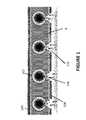
- FIG. 1is a drawing showing a cross-section (perpendicular to the channels) of one embodiment of the surgical safety drape of the present invention.
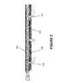
- FIG. 2is a drawing showing a cross-section (parallel to the channels) of the embodiment shown in FIG. 1 .
- FIG. 3is a drawing showing a top view of the embodiment shown in FIG. 1 .
- FIG. 4is a drawing showing a cross-section of another embodiment of the surgical safety drape of the present invention.
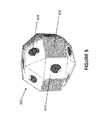
- FIG. 5is a drawing showing the polygonal ball used in the embodiment shown is FIG. 4 .
- FIG. 6is a drawing showing the composition of the plenum layer of the embodiment shown is FIG. 4 .
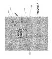
- FIG. 7is a drawing showing a surgical safety drape using a combination plenum layer.
- the present inventionrelates to surgical drapes having a mechanism for evacuating vapors, preferably fire producing and supporting vapors.
- the drapesare particularly useful for evacuating vapor trapped between the drape and a patient's skin during surgery.
- the surgical drapecontains a liquid-impervious layer, a porous layer, and hollow members sandwiched between the two layers to provide a pathway for evacuating vapors through the porous layer.
- the impervious and porous layers of the present inventioncan be made of components similar to commercially available disposable surgical drapes. These two components render this drape impervious to blood, fluids and bacteria. In this respect, this drape is similar in construction to many of the surgical drapes presently with full FDA approval and now being marketed. This construction is calculated to allow for successful completion of the FDA test battery for surgical drape approval.
- the middle of the drape between the two layers(also referred herein as the plenum layer), not in contact with the patient or open to the surgical field that provides its unique fire prevention vapor aspiration and ventilation capabilities, is composed of chemically biocompatible components with modifications allowing for increased structural integrity. These components are similarly biodegradable and do not represent a hazard to the environment, breaking down on incineration to carbon dioxide and water.
- the additional ability of this drape to increase the rigidity and support capabilities in desired drape sections due to conformational changes induced in the plenum layer during the procedurealso provides an additional margin of patient safety by modification of certain drape sections placed over critical patient body structures to resist the effect of heavy instruments compressing patient body structures beneath the drape.
- the plenum layer conformational changecan also provide a reinforcement area around the surgical site opening (fenestration) in the drape to provide structural strength.
- An adhesive materialis attached to the edge of the surgical field opening in the drape material to hold the drape in place around the surgical site and to minimize the passage of blood/fluids between the drape and the patient's body.
- the combination of the drape itself and the adhesive material around the perimeter of the surgical fieldusually provides a barrier between the surgical wound and the non-sterile remainder of the patients' body.
- the impervious layer of the surgical drapeis generally composed of a laminate, e.g. of polypropylene, polyurethane, and/or polyethylene materials or other similar non-toxic, biocompatible compounds.
- the porous layer of the surgical drapemay be made of the same material as the impervious layer but with pores built into the material connecting into the plenum layer. This porous layer is on the underside of the drape (when in use is in contact with the patient's skin) where the pores, open to the underside of the drape, provide a conduit for removal of the vapors above the patient's skin. These pores are important in providing a path for the evacuation of the fuel source on the patient's skin.
- the impervious and porous layersprovide a plenum layer that is sandwiched between the impervious and porous layers.
- That plenum layercontains structures unique to this invention that incorporate ventilation channels within the drape thickness to allow for gas movement through the structure of the drape itself, a mechanism for evacuating vapors that are trapped between the underside of the drape and the patient's skin when the surgical drape is in use.
- this plenum layeris provided beneath the impervious layers to provide the evacuation mechanism.
- Beneath the plenum layeris the porous layer containing ventilation pores open to the underside of the drape and fluidly connecting, through the porous layer, up to the plenum layer, which allow for movement of gases from the underside of the drape to the structures in the plenum layer for removal via the plenum layer.
- the plenum layerprovides mechanisms for evacuating vapors that are trapped between the porous layer and the patient's skin when the surgical safety drape is in use.
- a hollow memberis provided between the two layers (the plenum layer) to provide the evacuation mechanism
- the mechanism for evacuating vaporsincludes multiple channels 102 , between the impervious layer 104 and the porous layer 106 .
- the porous layerhaving pores 110 .
- Each of the channels 102has ports 108 on its wall to provide fluid communication with the space 8 between the two layers 104 and 106 , and with the pores 110 .
- the channels 102can be formed by, e.g. tubes placed between the two layers 104 and 106 .
- the channels 102are placed such that only one tube separating the two layers 104 and 106 . Multiple stacking of the channels 102 is to be avoided as that would add to the thickness of the drape without providing additional evacuation benefit.
- the ports 108 of the channels 102are preferably oriented toward the porous layer 106 (facing the porous layer 106 ) to facilitate evacuation of gases through the porous layer 106 and into the channels 102 , when a vacuum is applied to the interior of the channel.
- the channels 102can be constructed of various polymers, such as polyurethane, polyethylene, or polypropylene.
- the space 8 between layers 104 and 106is filled with a thermally insulating gel and the channels 102 are formed by elongated voids within the gel.
- the gelshould not block fluid communication between the pores 110 and the ports 108 .
- the gelcan be, but is not limited to, polyurethane, polyethylene, polypropylene, and/or other formulations having the required structural and flexible characteristics.
- the ports 108are formed on the surface of the channels 102 .
- the portsare formed such that they face the porous layer 106 directly, as shown in FIG. 1 .
- the material usedshould be sufficiently flexible to allow the surgical safety drape to conform to the patient's body shape when in use, without impediment to the surgical team.
- the channels 102have structural characteristics such that they remain open for the vacuum aspiration and ventilation functions.
- the channels 102when in use, are connected to a vacuum source, such as a vacuum pump, that can be used to apply a vacuum to the channels.
- a vacuum sourcesuch as a vacuum pump
- the channelsare connected in series or in parallel to a common vacuum source at the edge of the surgical safety drape.
- the vacuum appliedshould be sufficient to quickly withdraw gas through the porous layer 106 without collapsing the channels 102 .
- the channels 102should have sufficient rigidity to withstand the applied vacuum.
- the vacuum appliedis about 25 to about 150 cm of H 2 O, more preferably about 50 to about 75 cm of H 2 O.
- the channels 102are laterally separated from each other by a distance (center to center) of about 3 to about 7 mm, more preferably about 4 to about 6 mm.
- FIG. 3shows a top view of the drape 202 having multiple channels 102 therein.
- the channels 102are lead to a main aspiration tube 204 that is designed to be removably connected to a vacuum source via a connector 206 .
- the connector 206can be various vacuum connectors known in the art, such as push-pull connectors with self locking mechanisms.
- the surgical safety drapealso includes a portion that is designed to aspirate directly over the surgical drape opening (fenestration) where the surgical incision is contemplated. Its purpose is temporary, and is to provide for fast removal and drying of the disinfectant prep solution directly over the surgical site.
- this portion of the surgical safety drapeis preferably detached from the remainder of the safety drape, which is kept in place. This detachment leaves a dry surgical incision site ready for surgery yet remaining sterile and free of flammable vapors. This process promotes faster drying of the surgical site and decreases the operating room wait time for surgical disinfectant drying after sterile surgical prep.
- the mechanism for evacuating vaporsincludes a plurality of hollow balls 302 having holes thereon to allow free passage of gas therethrough.
- gasis evacuated through the porous layer 106 .
- Each ballhas rigidity sufficient to withstand the vacuum force applied between the two layers.
- it is preferred that the rigidity of the ballsis much higher than that just sufficient to withstand the force due to the supplied vacuum.
- the ballsmay be constructed from the following materials: polycarbonate, polypropylene, or polyurethane. Desirably, the balls are made sufficiently stiff to withstand being crushed by surgical objects placed on to the surgical safety drape. The crushing pressure on the ball should be greater than about 5 PSI.
- each ballis preferably composed of a plurality of polygonal surfaces 402 , where at least some of the surfaces 402 have holes 404 there on.
- the ballpreferably has a diameter or longest distance between opposing surfaces of about 1 to about 5 mm, more preferably about 2 to about 4 mm.
- abutting surfaces 406 on adjacent ballsare preferably roughened or contain corrugations to allow the balls to lock together to form a rigid surface as shall be apparent below.
- Each of the abutting surfaces 406preferably contains raised, interlocking pyramids on its surface (as illustrated in FIG. 5 ).
- the pyramidal like surfaces on the face of the polygonsinterlock due to slight movement (less than 0.5 mm) of the polygons, preventing the polygons to then move in any direction relative to each other, resulting in adjacent polygons to lock together to form and act collectively as a single rigid structural surface.
- This interlocking feature of the activated rigidity sectioncan be applied to vertical as well as horizontal rigidity as required in surgical safety drape design.
- FIG. 6show a preferred construction of the embodiment of the present invention with hollow balls 302 .
- the balls 302are aligned in a monolayer.
- Vertical plenum columns 502are placed in spaces between the balls 302 to confine each balls to a particular position in the plenum layer.
- the top and bottom of the plenum layerare then capped with the impervious layer 104 and the porous layer 106 (as illustrated in FIG. 4 ).
- the top and bottom of the plenum columns 502are attached permanently to the two layers, respectively.
- the plenum columns 502are positioned such that the balls 302 are kept relatively in place and to prevent movement of the balls, particularly not allowing the balls to stack on top of one another. This way, the monolayer of balls is maintained throughout the surgical drape.
- Each of the plenum columnspreferably has a circular cross-section with a diameter of about 0.25 to about 1.25 mm, more preferably about 0.5 to about 1 mm.
- the plenum columns 502are preferably sufficiently flexible to allow slight movement in the balls 302 to allow them to come in direct contact with each other when a vacuum is applied, and to come apart when the vacuum is released.
- the movement of the ballshould be no more than about 2 mm, preferably no more than about 0.5 mm.
- the plenum columns 502can be manufacture using polymeric materials, such as polyurethane, polypropylene, or combinations thereof.
- Surrounding the balls in the middle plenum layermay be just air space, or in certain embodiments, may be gel-like compound composed also of formulations, such as polyurethane and polypropylene, that render the balls enclosed in a sealed plenum compartment wherein the only conduits for gas movement are the perforations in the balls allowing transmission of a vacuum effect from ball to adjacent ball when a vacuum is induced to the plenum layer.
- formulationssuch as polyurethane and polypropylene
- the top and bottom ends of the plenum columns 502are permanently anchored to the impervious layer 104 and the porous layer 106 , respectively. This can be accomplished many different ways. In certain embodiments, those ends are directly attached to the layers 104 and 106 using, e.g. a glue. Alternatively, the columns can be molded as part of a large sheet, where the sheet is then attached to impervious 104 and porous 106 layers. Preferably, the attachments occur using a using a flexible glue that does not increase the stiffness of the over surgical drape.
- the use of the hollow ballshas the advantage of being able to provide stiffness to the surgical drape when a vacuum is supplied.
- the ballswhen not under vacuum, are sufficiently separated from adjacent balls, such that they allow the surgical drape to be flexible.
- the ballswhen a vacuum is applied, the balls, because they are constrained by the plenum columns 502 come into contact at their abutting surfaces 406 .
- the corrugations at the abutting surfaces 406allow the balls to lock together, thereby producing a stiff surgical drape.
- the stiffness of the drapeallows it to form a surface for the surgeon to place equipments without putting undue pressure, by weight, on the patient.
- the equipmentcan be cameras, forceps, probes, etc.
- the stiff surfacedistributes the pressure over the entire area covered by the drape, rather than allowing localized pressure, which reduces discomfort to the patient.
- a surgical drape of the present inventionmay incorporate both the hollow balls and the evacuation channels disclosed above.
- hollow ballsare used in portions of the drape where stiffness is required, while the evacuation channels are used in portions where flexibility under vacuum is required.
- FIG. 7shows an embodiment of the present invention where the areas 702 closest (within about 50 to about 100 cm) to the fenestration uses the evacuation channels 102 , while portions 704 beyond this area uses the hollow balls 302 .
- FIG. 7shows that the fenestration, itself, contains a temporary sheet 706 that included evacuation channels 102 .
- This temporary sheet 706is used to evacuate vapors in that area and is removed just before the surgeon is ready to perform the surgery.
- the portions 704 furthest away from the fenestrationuses hollow balls to effect evacuation of vapors during surgery.
- stiffnessis desirable during surgery in portion 704 to provide a surface for the surgeon to place equipment for ready access.
- the surgical drape of the present inventionis placed over an area of the patient with the porous layer 106 toward the skin of the patient.
- the drapeis then connected to a vacuum source to apply a vacuum to the plenum space ventilation section between impervious layer 104 and the porous layer 106 .
- the vacuumremoves any flammable fuel trapped between the surgical drape and the patient to minimize fire risks to the patient during surgery.
- the vacuumneed not be on during surgery after sufficient time is elapsed to assure no further evaporation of alcohol is occurring.
- the vacuum aspirationcan be turned off. If needed, the vacuum can be activated to lock the balls 302 together to form a rigid surface for placement of equipment.
- the surgical safety drape of the present inventioncan also be used as a warming blanket.
- the air flowis simply reversed and warm air is blown on to the patient's skin.
- warming of the patientcan be controlled by providing the patient with warmed gas blown through the surgical safety drape and onto the patient's skin.
- a warmed gaspreferably at about 36 to 60° C., more preferably about 38 to about 40° C., and most preferably about 38° C., is provided to the patient by pumping the warm gas, preferably air, through the surgical safety drape plenum layer and though the porous layer to the patient's skin.
- temperature controlis used for managing the temperature of the gas to warm the body to normal temperature or for treatment of certain conditions, such as hypothermia commonly found under general anesthesia.
- the system of the present inventionfurther requires the ability to reverse the flow of the vacuum.
- the surgical safety drapecan be plugged directly to a pump to provide warm air.
- the system for providing warm gasincludes a pump and a control system to control the temperature of the gas and to adjust the temperature of the gas.
- the system to modify the gas temperaturecan be a simple heating element placed in the path of the gas flow. That heating and/or cooling element can be controlled directly by a system which heats or cools the temperature of the gas depending on a set temperature.
- a desired temperatureis set on the controller, which is connected to a temperature sensor placed in the flow path of the gas. Depending on the temperature of the gas, the controller activates the heating element to heat the gas.
- the controlleractivates the heating element to heat the gas until the desired temperature is reached.
- the controllercan heat the gas based on binary control.
- sophisticated controllerscan be programmed to control the rate of heating based on the difference between the desired temperature and the gas temperature.
Landscapes
- Health & Medical Sciences (AREA)
- Life Sciences & Earth Sciences (AREA)
- Animal Behavior & Ethology (AREA)
- Heart & Thoracic Surgery (AREA)
- Biomedical Technology (AREA)
- Engineering & Computer Science (AREA)
- General Health & Medical Sciences (AREA)
- Public Health (AREA)
- Veterinary Medicine (AREA)
- Surgery (AREA)
- Vascular Medicine (AREA)
- Medical Informatics (AREA)
- Molecular Biology (AREA)
- Surgical Instruments (AREA)
Abstract
Description
Claims (18)
Priority Applications (3)
| Application Number | Priority Date | Filing Date | Title |
|---|---|---|---|
| US13/836,918US8893721B2 (en) | 2013-03-15 | 2013-03-15 | Surgical drape with vapor evacuation |
| PCT/US2014/024636WO2014150952A1 (en) | 2013-03-15 | 2014-03-12 | Surgical drape with vapor evacuation |
| EP14768113.4AEP2983607A4 (en) | 2013-03-15 | 2014-03-12 | Surgical drape with vapor evacuation |
Applications Claiming Priority (1)
| Application Number | Priority Date | Filing Date | Title |
|---|---|---|---|
| US13/836,918US8893721B2 (en) | 2013-03-15 | 2013-03-15 | Surgical drape with vapor evacuation |
Publications (2)
| Publication Number | Publication Date |
|---|---|
| US20140261458A1 US20140261458A1 (en) | 2014-09-18 |
| US8893721B2true US8893721B2 (en) | 2014-11-25 |
Family
ID=51521806
Family Applications (1)
| Application Number | Title | Priority Date | Filing Date |
|---|---|---|---|
| US13/836,918Expired - Fee RelatedUS8893721B2 (en) | 2013-03-15 | 2013-03-15 | Surgical drape with vapor evacuation |
Country Status (3)
| Country | Link |
|---|---|
| US (1) | US8893721B2 (en) |
| EP (1) | EP2983607A4 (en) |
| WO (1) | WO2014150952A1 (en) |
Cited By (3)
| Publication number | Priority date | Publication date | Assignee | Title |
|---|---|---|---|---|
| US9937006B2 (en) | 2010-12-14 | 2018-04-10 | Allen Medical Systems, Inc. | Multi-site surgical drape and method |
| US20210369378A1 (en)* | 2020-05-28 | 2021-12-02 | Mazor Robotics Ltd. | System and method for drape volume control |
| US12440299B2 (en)* | 2021-05-26 | 2025-10-14 | Mazor Robotics Ltd. | System and method for drape volume control |
Families Citing this family (2)
| Publication number | Priority date | Publication date | Assignee | Title |
|---|---|---|---|---|
| JP7002079B2 (en)* | 2018-10-30 | 2022-01-20 | 大日精化工業株式会社 | Surgical drape |
| CN114587620A (en)* | 2022-04-22 | 2022-06-07 | 陈树雄 | Sterile hole towel for medical and aesthetic operations and use method thereof |
Citations (55)
| Publication number | Priority date | Publication date | Assignee | Title |
|---|---|---|---|---|
| US2305289A (en)* | 1939-06-17 | 1942-12-15 | Coburg Hermann | Surgical appliance |
| GB1128166A (en) | 1965-04-14 | 1968-09-25 | Lacy Hulbert And Company Ltd | Improvements in drying apparatus |
| US3763857A (en)* | 1972-04-24 | 1973-10-09 | Kimberly Clark Co | Surgical drape |
| US4136222A (en) | 1977-04-18 | 1979-01-23 | Minnesota Mining And Manufacturing Company | Thermally insulating sheet material |
| US4323069A (en) | 1980-05-12 | 1982-04-06 | The Procter & Gamble Company | Disposable absorbent article having an intermediate layer interposed between the topsheet and the absorbent core |
| US4848364A (en)* | 1986-10-23 | 1989-07-18 | Patentico Ltd. | Covering sheet which can be made form-retaining |
| US5106629A (en) | 1989-10-20 | 1992-04-21 | Ndm Acquisition Corp. | Transparent hydrogel wound dressing |
| US5941907A (en)* | 1997-06-02 | 1999-08-24 | Augustine Medical, Inc. | Surgical barrier device incorporating an inflatable thermal blanket with a surgical drape to provide thermal control and surgical access |
| US6345623B1 (en)* | 1997-09-12 | 2002-02-12 | Keith Patrick Heaton | Surgical drape and suction head for wound treatment |
| US6395955B1 (en) | 1998-06-29 | 2002-05-28 | The Procter & Gamble Company | Diaper including feces modification agent |
| US20020128578A1 (en)* | 1997-08-01 | 2002-09-12 | 3M Innovative Properties Company | Medical article having fluid control film |
| US6685681B2 (en) | 2000-11-29 | 2004-02-03 | Hill-Rom Services, Inc. | Vacuum therapy and cleansing dressing for wounds |
| US20040225341A1 (en) | 2002-07-11 | 2004-11-11 | Life Recovery Systems, Inc. | Apparatus for altering the body temperature of a patient |
| US6820622B1 (en)* | 2002-06-07 | 2004-11-23 | Leonides Y. Teves | Thermal surgical drape |
| WO2005047792A2 (en) | 2003-11-14 | 2005-05-26 | Meir Almog | Method and system for drying building structures |
| WO2005105176A1 (en) | 2004-04-27 | 2005-11-10 | Smith & Nephew, Plc | Wound cleansing apparatus with flowstress |
| US6979324B2 (en) | 2002-09-13 | 2005-12-27 | Neogen Technologies, Inc. | Closed wound drainage system |
| US20060264796A1 (en)* | 1995-09-05 | 2006-11-23 | Argentum Medical, Llc | Medical device |
| US20070185463A1 (en) | 2006-02-07 | 2007-08-09 | Tyco Heal Thcare Group Lp | Surgical wound dressing |
| US20070225663A1 (en) | 2004-06-21 | 2007-09-27 | Watt Paul W | Wound dressings for vacuum therapy |
| US20080053462A1 (en)* | 2006-09-05 | 2008-03-06 | Teves Leonides Y | Surgical drape with convective heat therapy device |
| US20080103462A1 (en) | 2006-10-30 | 2008-05-01 | Stuart Wenzel | Wound healing patch with integral passive vacuum and electrostimulation |
| US20080139987A1 (en)* | 2006-11-09 | 2008-06-12 | Archel Ambrosio | Porous bioresorbable linked dressing comprising microspheres and methods of making same |
| US20090312723A1 (en) | 2005-04-27 | 2009-12-17 | Blott Patrick L | Wound treatment apparatus and method |
| US7645269B2 (en) | 2001-04-30 | 2010-01-12 | Kci Licensing, Inc. | Gradient wound treatment system and method |
| US20100036334A1 (en) | 2008-08-08 | 2010-02-11 | Tyco Healthcare Group Lp | Wound Dressing of Continuous Fibers |
| US7723560B2 (en) | 2001-12-26 | 2010-05-25 | Lockwood Jeffrey S | Wound vacuum therapy dressing kit |
| US20100160877A1 (en) | 2008-12-24 | 2010-06-24 | Jonathan Kagan | Membranes, systems, and methods for applying reduced pressure to a subcutaneous tissue site |
| US20100174250A1 (en) | 2009-01-07 | 2010-07-08 | Spiracur Inc. | Reduced pressure therapy of the sacral region |
| US20100262094A1 (en) | 2007-11-21 | 2010-10-14 | T.J. Smith & Nephew, Limited | Suction device and dressing |
| US20100263678A1 (en) | 2006-02-22 | 2010-10-21 | Baumann Nicholas R | Patient warming drape |
| US7825289B2 (en) | 2008-05-16 | 2010-11-02 | Tyco Healthcare Group Lp | Wound dressing adhesive compression device |
| US20100300708A1 (en) | 2009-05-28 | 2010-12-02 | University Of Southern California | Detection and suppression of airway / drape fires during surgical procedures |
| US20110009838A1 (en) | 2007-11-21 | 2011-01-13 | Smith & Nephew Plc | Vacuum assisted wound dressing |
| US7896856B2 (en) | 2002-08-21 | 2011-03-01 | Robert Petrosenko | Wound packing for preventing wound closure |
| US7910791B2 (en) | 2000-05-22 | 2011-03-22 | Coffey Arthur C | Combination SIS and vacuum bandage and method |
| US20110087179A2 (en) | 2003-10-28 | 2011-04-14 | Patrick Blott | Wound cleansing apparatus in-situ |
| US20110112492A1 (en) | 2008-04-04 | 2011-05-12 | Vivek Bharti | Wound dressing with micropump |
| US7976519B2 (en) | 2002-12-31 | 2011-07-12 | Kci Licensing, Inc. | Externally-applied patient interface system and method |
| US20110213319A1 (en) | 2004-04-27 | 2011-09-01 | Patrick Lewis Blott | Wound treatment apparatus and method |
| US8021347B2 (en) | 2008-07-21 | 2011-09-20 | Tyco Healthcare Group Lp | Thin film wound dressing |
| US8034038B2 (en)* | 2002-09-13 | 2011-10-11 | Neogen Technologies, Inc. | Closed wound drainage system |
| US8048046B2 (en) | 2008-05-21 | 2011-11-01 | Tyco Healthcare Group Lp | Wound therapy system with housing and canister support |
| US8057447B2 (en) | 2007-05-10 | 2011-11-15 | Kci Licensing Inc. | Reduced pressure wound dressing having a wound contact surface with columnar protrusions |
| US20120071841A1 (en) | 2006-06-02 | 2012-03-22 | Kci Medical Resources | Assemblies, systems, and methods for vacuum assisted internal drainage during wound healing |
| US8147468B2 (en) | 2008-05-30 | 2012-04-03 | Kci Licensing, Inc. | Reduced-pressure, linear-wound treatment systems |
| US8152785B2 (en) | 2008-03-13 | 2012-04-10 | Tyco Healthcare Group Lp | Vacuum port for vacuum wound therapy |
| US20120095419A1 (en) | 2007-08-03 | 2012-04-19 | Birgit Riesinger | Wound care article having an absorbent shell |
| US8162907B2 (en) | 2009-01-20 | 2012-04-24 | Tyco Healthcare Group Lp | Method and apparatus for bridging from a dressing in negative pressure wound therapy |
| US8162909B2 (en) | 2005-09-15 | 2012-04-24 | Smith & Nephew Plc | Negative pressure wound treatment |
| US20120143113A1 (en)* | 2010-12-07 | 2012-06-07 | Timothy Mark Robinson | Wound healing apparatus for promoting granulation and epithelialisation at a tissue site |
| US20120157945A1 (en) | 2010-12-15 | 2012-06-21 | Timothy Mark Robinson | Foam Dressing with Integral Porous Film |
| US8207392B2 (en) | 2005-09-07 | 2012-06-26 | Tyco Healthcare Group Lp | Self contained wound dressing with micropump |
| US8246591B2 (en) | 2009-01-23 | 2012-08-21 | Tyco Healthcare Group Lp | Flanged connector for wound therapy |
| US8257328B2 (en) | 2008-07-08 | 2012-09-04 | Tyco Healthcare Group Lp | Portable negative pressure wound therapy device |
- 2013
- 2013-03-15USUS13/836,918patent/US8893721B2/ennot_activeExpired - Fee Related
- 2014
- 2014-03-12WOPCT/US2014/024636patent/WO2014150952A1/enactiveApplication Filing
- 2014-03-12EPEP14768113.4Apatent/EP2983607A4/ennot_activeWithdrawn
Patent Citations (60)
| Publication number | Priority date | Publication date | Assignee | Title |
|---|---|---|---|---|
| US2305289A (en)* | 1939-06-17 | 1942-12-15 | Coburg Hermann | Surgical appliance |
| GB1128166A (en) | 1965-04-14 | 1968-09-25 | Lacy Hulbert And Company Ltd | Improvements in drying apparatus |
| US3763857A (en)* | 1972-04-24 | 1973-10-09 | Kimberly Clark Co | Surgical drape |
| US4136222A (en) | 1977-04-18 | 1979-01-23 | Minnesota Mining And Manufacturing Company | Thermally insulating sheet material |
| US4323069A (en) | 1980-05-12 | 1982-04-06 | The Procter & Gamble Company | Disposable absorbent article having an intermediate layer interposed between the topsheet and the absorbent core |
| US4848364A (en)* | 1986-10-23 | 1989-07-18 | Patentico Ltd. | Covering sheet which can be made form-retaining |
| US5106629A (en) | 1989-10-20 | 1992-04-21 | Ndm Acquisition Corp. | Transparent hydrogel wound dressing |
| US20060264796A1 (en)* | 1995-09-05 | 2006-11-23 | Argentum Medical, Llc | Medical device |
| US5941907A (en)* | 1997-06-02 | 1999-08-24 | Augustine Medical, Inc. | Surgical barrier device incorporating an inflatable thermal blanket with a surgical drape to provide thermal control and surgical access |
| US20020128578A1 (en)* | 1997-08-01 | 2002-09-12 | 3M Innovative Properties Company | Medical article having fluid control film |
| US6345623B1 (en)* | 1997-09-12 | 2002-02-12 | Keith Patrick Heaton | Surgical drape and suction head for wound treatment |
| US7886746B2 (en)* | 1997-09-12 | 2011-02-15 | Kci Licensing, Inc. | Surgical drape and suction head for wound treatment |
| US7117869B2 (en)* | 1997-09-12 | 2006-10-10 | Kci Licensing, Inc. | Surgical drape and suction head for wound treatment |
| US6395955B1 (en) | 1998-06-29 | 2002-05-28 | The Procter & Gamble Company | Diaper including feces modification agent |
| US7910791B2 (en) | 2000-05-22 | 2011-03-22 | Coffey Arthur C | Combination SIS and vacuum bandage and method |
| US6685681B2 (en) | 2000-11-29 | 2004-02-03 | Hill-Rom Services, Inc. | Vacuum therapy and cleansing dressing for wounds |
| US7645269B2 (en) | 2001-04-30 | 2010-01-12 | Kci Licensing, Inc. | Gradient wound treatment system and method |
| US7723560B2 (en) | 2001-12-26 | 2010-05-25 | Lockwood Jeffrey S | Wound vacuum therapy dressing kit |
| US6820622B1 (en)* | 2002-06-07 | 2004-11-23 | Leonides Y. Teves | Thermal surgical drape |
| US20040225341A1 (en) | 2002-07-11 | 2004-11-11 | Life Recovery Systems, Inc. | Apparatus for altering the body temperature of a patient |
| US7896856B2 (en) | 2002-08-21 | 2011-03-01 | Robert Petrosenko | Wound packing for preventing wound closure |
| US6979324B2 (en) | 2002-09-13 | 2005-12-27 | Neogen Technologies, Inc. | Closed wound drainage system |
| US8034038B2 (en)* | 2002-09-13 | 2011-10-11 | Neogen Technologies, Inc. | Closed wound drainage system |
| US7976519B2 (en) | 2002-12-31 | 2011-07-12 | Kci Licensing, Inc. | Externally-applied patient interface system and method |
| US8080702B2 (en) | 2003-10-28 | 2011-12-20 | Smith & Nephew Plc | Wound cleansing apparatus in-situ |
| US20110087179A2 (en) | 2003-10-28 | 2011-04-14 | Patrick Blott | Wound cleansing apparatus in-situ |
| WO2005047792A2 (en) | 2003-11-14 | 2005-05-26 | Meir Almog | Method and system for drying building structures |
| US20110213319A1 (en) | 2004-04-27 | 2011-09-01 | Patrick Lewis Blott | Wound treatment apparatus and method |
| WO2005105176A1 (en) | 2004-04-27 | 2005-11-10 | Smith & Nephew, Plc | Wound cleansing apparatus with flowstress |
| US20070225663A1 (en) | 2004-06-21 | 2007-09-27 | Watt Paul W | Wound dressings for vacuum therapy |
| US20090312723A1 (en) | 2005-04-27 | 2009-12-17 | Blott Patrick L | Wound treatment apparatus and method |
| US8207392B2 (en) | 2005-09-07 | 2012-06-26 | Tyco Healthcare Group Lp | Self contained wound dressing with micropump |
| US8162909B2 (en) | 2005-09-15 | 2012-04-24 | Smith & Nephew Plc | Negative pressure wound treatment |
| US20070185463A1 (en) | 2006-02-07 | 2007-08-09 | Tyco Heal Thcare Group Lp | Surgical wound dressing |
| US20100263678A1 (en) | 2006-02-22 | 2010-10-21 | Baumann Nicholas R | Patient warming drape |
| US20120071841A1 (en) | 2006-06-02 | 2012-03-22 | Kci Medical Resources | Assemblies, systems, and methods for vacuum assisted internal drainage during wound healing |
| US20080053462A1 (en)* | 2006-09-05 | 2008-03-06 | Teves Leonides Y | Surgical drape with convective heat therapy device |
| US20080103462A1 (en) | 2006-10-30 | 2008-05-01 | Stuart Wenzel | Wound healing patch with integral passive vacuum and electrostimulation |
| US20080139987A1 (en)* | 2006-11-09 | 2008-06-12 | Archel Ambrosio | Porous bioresorbable linked dressing comprising microspheres and methods of making same |
| US8057447B2 (en) | 2007-05-10 | 2011-11-15 | Kci Licensing Inc. | Reduced pressure wound dressing having a wound contact surface with columnar protrusions |
| US20120095419A1 (en) | 2007-08-03 | 2012-04-19 | Birgit Riesinger | Wound care article having an absorbent shell |
| US20110009838A1 (en) | 2007-11-21 | 2011-01-13 | Smith & Nephew Plc | Vacuum assisted wound dressing |
| US20100262094A1 (en) | 2007-11-21 | 2010-10-14 | T.J. Smith & Nephew, Limited | Suction device and dressing |
| US8152785B2 (en) | 2008-03-13 | 2012-04-10 | Tyco Healthcare Group Lp | Vacuum port for vacuum wound therapy |
| US20110112492A1 (en) | 2008-04-04 | 2011-05-12 | Vivek Bharti | Wound dressing with micropump |
| US7825289B2 (en) | 2008-05-16 | 2010-11-02 | Tyco Healthcare Group Lp | Wound dressing adhesive compression device |
| US8048046B2 (en) | 2008-05-21 | 2011-11-01 | Tyco Healthcare Group Lp | Wound therapy system with housing and canister support |
| US8147468B2 (en) | 2008-05-30 | 2012-04-03 | Kci Licensing, Inc. | Reduced-pressure, linear-wound treatment systems |
| US8167856B2 (en) | 2008-05-30 | 2012-05-01 | Kci Licensing, Inc | Inflatable bladder dressings, systems, and methods |
| US8188331B2 (en) | 2008-05-30 | 2012-05-29 | Kci Licensing, Inc. | See-through, reduced-pressure dressings and systems |
| US8257328B2 (en) | 2008-07-08 | 2012-09-04 | Tyco Healthcare Group Lp | Portable negative pressure wound therapy device |
| US8021347B2 (en) | 2008-07-21 | 2011-09-20 | Tyco Healthcare Group Lp | Thin film wound dressing |
| US20100036334A1 (en) | 2008-08-08 | 2010-02-11 | Tyco Healthcare Group Lp | Wound Dressing of Continuous Fibers |
| US20100160877A1 (en) | 2008-12-24 | 2010-06-24 | Jonathan Kagan | Membranes, systems, and methods for applying reduced pressure to a subcutaneous tissue site |
| US20100174250A1 (en) | 2009-01-07 | 2010-07-08 | Spiracur Inc. | Reduced pressure therapy of the sacral region |
| US8162907B2 (en) | 2009-01-20 | 2012-04-24 | Tyco Healthcare Group Lp | Method and apparatus for bridging from a dressing in negative pressure wound therapy |
| US8246591B2 (en) | 2009-01-23 | 2012-08-21 | Tyco Healthcare Group Lp | Flanged connector for wound therapy |
| US20100300708A1 (en) | 2009-05-28 | 2010-12-02 | University Of Southern California | Detection and suppression of airway / drape fires during surgical procedures |
| US20120143113A1 (en)* | 2010-12-07 | 2012-06-07 | Timothy Mark Robinson | Wound healing apparatus for promoting granulation and epithelialisation at a tissue site |
| US20120157945A1 (en) | 2010-12-15 | 2012-06-21 | Timothy Mark Robinson | Foam Dressing with Integral Porous Film |
Non-Patent Citations (1)
| Title |
|---|
| Korean Search Report dated Jul. 11, 2014 issued in PCT/US2014/024636. |
Cited By (5)
| Publication number | Priority date | Publication date | Assignee | Title |
|---|---|---|---|---|
| US9937006B2 (en) | 2010-12-14 | 2018-04-10 | Allen Medical Systems, Inc. | Multi-site surgical drape and method |
| US11013570B2 (en) | 2010-12-14 | 2021-05-25 | Allen Medical Systems, Inc. | Multi-site surgical drape apparatus |
| US12127811B2 (en) | 2010-12-14 | 2024-10-29 | Allen Medical Systems, Inc. | Lateral supports for dual-column surgical table |
| US20210369378A1 (en)* | 2020-05-28 | 2021-12-02 | Mazor Robotics Ltd. | System and method for drape volume control |
| US12440299B2 (en)* | 2021-05-26 | 2025-10-14 | Mazor Robotics Ltd. | System and method for drape volume control |
Also Published As
| Publication number | Publication date |
|---|---|
| US20140261458A1 (en) | 2014-09-18 |
| EP2983607A1 (en) | 2016-02-17 |
| WO2014150952A1 (en) | 2014-09-25 |
| EP2983607A4 (en) | 2016-12-14 |
Similar Documents
| Publication | Publication Date | Title |
|---|---|---|
| US20130269713A1 (en) | Surgical appliance kit and system for releasably securing a surgical appliance to a surgical field and method of assembling the surgical applicance kit | |
| US7763060B2 (en) | Patient warming drape | |
| Hockstein et al. | Maintenance of hemostasis in transoral robotic surgery | |
| US20090216069A1 (en) | Enclosure for surgical procedures | |
| BRPI0617967A2 (en) | dressing set for a wound or incision, and hemostat | |
| US8893721B2 (en) | Surgical drape with vapor evacuation | |
| US7879078B2 (en) | Use of convective air warming system for patient care | |
| US20220168013A1 (en) | Sterilizing surgical access devices | |
| MCGINNIS et al. | Management of hemorrhage during laparoscopy | |
| KR20150126629A (en) | Surgical access assembly and method of using same | |
| US20220096190A1 (en) | Fenestration Coverings, Procedural Drapes, and Methods Thereof | |
| US20210386445A1 (en) | Nasal smoke evacuator | |
| CN203789996U (en) | Separating forceps with suction function for laparoscopic operations | |
| JP2009089900A (en) | Member for exclusion in surgery | |
| JP2020527064A (en) | A set with a suction device suitable for placement on the wound and / or incision | |
| Moskowitz | Fire in the operating room during open heart surgery: a case report. | |
| Fidler | Techniques of laser burn surgery | |
| Morodomi et al. | Application of continuous negative pressure irrigation and negative pressure fixation to treat a bronchopleural fistula with thoracic empyema | |
| Nel et al. | Consensus statement regarding minimally invasive surgery during the COVID-19 pandemic | |
| Hammer et al. | Abdominal access techniques | |
| Nel et al. | SASES consensus statement regarding minimally invasive surgery during the COVID-19 pandemic | |
| African | Consensus statement regarding minimally invasive surgery during the COVID-19 pandemic | |
| CN203970580U (en) | Disposal sterilized operation bag | |
| JP3265452B2 (en) | Medical peeling suction beak tube | |
| Liu et al. | Emphysema surgery–loop ligation approach |
Legal Events
| Date | Code | Title | Description |
|---|---|---|---|
| FEPP | Fee payment procedure | Free format text:PAYOR NUMBER ASSIGNED (ORIGINAL EVENT CODE: ASPN); ENTITY STATUS OF PATENT OWNER: SMALL ENTITY | |
| STCF | Information on status: patent grant | Free format text:PATENTED CASE | |
| AS | Assignment | Owner name:BIOEMERGE TECHNOLOGY, LLC, CALIFORNIA Free format text:ASSIGNMENT OF ASSIGNORS INTEREST;ASSIGNOR:FUTRELL MEDICAL CORPORATION;REEL/FRAME:036768/0403 Effective date:20151007 Owner name:FUTRELL MEDICAL CORPORATION, CALIFORNIA Free format text:ASSIGNMENT OF ASSIGNORS INTEREST;ASSIGNOR:FUTRELL, JAMES;REEL/FRAME:036768/0354 Effective date:20151007 | |
| FEPP | Fee payment procedure | Free format text:MAINTENANCE FEE REMINDER MAILED (ORIGINAL EVENT CODE: REM.) | |
| FEPP | Fee payment procedure | Free format text:SURCHARGE FOR LATE PAYMENT, SMALL ENTITY (ORIGINAL EVENT CODE: M2554); ENTITY STATUS OF PATENT OWNER: SMALL ENTITY | |
| MAFP | Maintenance fee payment | Free format text:PAYMENT OF MAINTENANCE FEE, 4TH YR, SMALL ENTITY (ORIGINAL EVENT CODE: M2551); ENTITY STATUS OF PATENT OWNER: SMALL ENTITY Year of fee payment:4 | |
| FEPP | Fee payment procedure | Free format text:MAINTENANCE FEE REMINDER MAILED (ORIGINAL EVENT CODE: REM.); ENTITY STATUS OF PATENT OWNER: SMALL ENTITY | |
| LAPS | Lapse for failure to pay maintenance fees | Free format text:PATENT EXPIRED FOR FAILURE TO PAY MAINTENANCE FEES (ORIGINAL EVENT CODE: EXP.); ENTITY STATUS OF PATENT OWNER: SMALL ENTITY | |
| STCH | Information on status: patent discontinuation | Free format text:PATENT EXPIRED DUE TO NONPAYMENT OF MAINTENANCE FEES UNDER 37 CFR 1.362 | |
| FP | Lapsed due to failure to pay maintenance fee | Effective date:20221125 |