US8893714B2 - Expansion joints for panels in solar boilers - Google Patents
Expansion joints for panels in solar boilersDownload PDFInfo
- Publication number
- US8893714B2 US8893714B2US12/701,999US70199910AUS8893714B2US 8893714 B2US8893714 B2US 8893714B2US 70199910 AUS70199910 AUS 70199910AUS 8893714 B2US8893714 B2US 8893714B2
- Authority
- US
- United States
- Prior art keywords
- panel
- receiver
- boiler
- panels
- tubes
- Prior art date
- Legal status (The legal status is an assumption and is not a legal conclusion. Google has not performed a legal analysis and makes no representation as to the accuracy of the status listed.)
- Expired - Fee Related, expires
Links
Images


Classifications
- F24J2/07—
- F—MECHANICAL ENGINEERING; LIGHTING; HEATING; WEAPONS; BLASTING
- F24—HEATING; RANGES; VENTILATING
- F24S—SOLAR HEAT COLLECTORS; SOLAR HEAT SYSTEMS
- F24S10/00—Solar heat collectors using working fluids
- F—MECHANICAL ENGINEERING; LIGHTING; HEATING; WEAPONS; BLASTING
- F24—HEATING; RANGES; VENTILATING
- F24S—SOLAR HEAT COLLECTORS; SOLAR HEAT SYSTEMS
- F24S40/00—Safety or protection arrangements of solar heat collectors; Preventing malfunction of solar heat collectors
- F24S40/80—Accommodating differential expansion of solar collector elements
- F24J2/245—
- F—MECHANICAL ENGINEERING; LIGHTING; HEATING; WEAPONS; BLASTING
- F24—HEATING; RANGES; VENTILATING
- F24S—SOLAR HEAT COLLECTORS; SOLAR HEAT SYSTEMS
- F24S10/00—Solar heat collectors using working fluids
- F24S10/25—Solar heat collectors using working fluids having two or more passages for the same working fluid layered in direction of solar-rays, e.g. having upper circulation channels connected with lower circulation channels
- F—MECHANICAL ENGINEERING; LIGHTING; HEATING; WEAPONS; BLASTING
- F24—HEATING; RANGES; VENTILATING
- F24S—SOLAR HEAT COLLECTORS; SOLAR HEAT SYSTEMS
- F24S10/00—Solar heat collectors using working fluids
- F24S10/70—Solar heat collectors using working fluids the working fluids being conveyed through tubular absorbing conduits
- F24S10/74—Solar heat collectors using working fluids the working fluids being conveyed through tubular absorbing conduits the tubular conduits are not fixed to heat absorbing plates and are not touching each other
- F24S10/742—Solar heat collectors using working fluids the working fluids being conveyed through tubular absorbing conduits the tubular conduits are not fixed to heat absorbing plates and are not touching each other the conduits being parallel to each other
- F—MECHANICAL ENGINEERING; LIGHTING; HEATING; WEAPONS; BLASTING
- F24—HEATING; RANGES; VENTILATING
- F24S—SOLAR HEAT COLLECTORS; SOLAR HEAT SYSTEMS
- F24S20/00—Solar heat collectors specially adapted for particular uses or environments
- F24S20/20—Solar heat collectors for receiving concentrated solar energy, e.g. receivers for solar power plants
- Y—GENERAL TAGGING OF NEW TECHNOLOGICAL DEVELOPMENTS; GENERAL TAGGING OF CROSS-SECTIONAL TECHNOLOGIES SPANNING OVER SEVERAL SECTIONS OF THE IPC; TECHNICAL SUBJECTS COVERED BY FORMER USPC CROSS-REFERENCE ART COLLECTIONS [XRACs] AND DIGESTS
- Y02—TECHNOLOGIES OR APPLICATIONS FOR MITIGATION OR ADAPTATION AGAINST CLIMATE CHANGE
- Y02E—REDUCTION OF GREENHOUSE GAS [GHG] EMISSIONS, RELATED TO ENERGY GENERATION, TRANSMISSION OR DISTRIBUTION
- Y02E10/00—Energy generation through renewable energy sources
- Y02E10/40—Solar thermal energy, e.g. solar towers
- Y02E10/41—
- Y—GENERAL TAGGING OF NEW TECHNOLOGICAL DEVELOPMENTS; GENERAL TAGGING OF CROSS-SECTIONAL TECHNOLOGIES SPANNING OVER SEVERAL SECTIONS OF THE IPC; TECHNICAL SUBJECTS COVERED BY FORMER USPC CROSS-REFERENCE ART COLLECTIONS [XRACs] AND DIGESTS
- Y02—TECHNOLOGIES OR APPLICATIONS FOR MITIGATION OR ADAPTATION AGAINST CLIMATE CHANGE
- Y02E—REDUCTION OF GREENHOUSE GAS [GHG] EMISSIONS, RELATED TO ENERGY GENERATION, TRANSMISSION OR DISTRIBUTION
- Y02E10/00—Energy generation through renewable energy sources
- Y02E10/40—Solar thermal energy, e.g. solar towers
- Y02E10/44—Heat exchange systems
Definitions
- the present inventionrelates to solar power production, and more particularly, to solar receiver panels for use in solar boilers.
- Solar power generationhas been considered a viable source to help provide for energy needs in a time of increasing consciousness of the environmental aspects of power production.
- Solar energy productionrelies mainly on the ability to collect and convert energy freely available from the sun and can be produced with very little impact on the environment.
- Solar powercan be utilized without creating radioactive waste as in nuclear power production, and without producing pollutant emissions including greenhouse gases as in fossil fuel power production.
- Solar power productionis independent of fluctuating fuel costs and does not consume non-renewable resources.
- Solar power generatorsgenerally employ fields of controlled mirrors, called heliostats, to gather and concentrate sunlight on a receiver to provide a heat source for power production.
- a solar receivertypically takes the form of a panel of tubes conveying a working fluid therethrough.
- Previous solar generatorshave used working fluids such as molten salt because it has the ability to store energy, allowing power generation when there is no solar radiation.
- the heated working fluidsare typically conveyed to a heat exchanger where they release heat into a second working fluid such as air, water, or steam. Power is generated by driving heated air or steam through a turbine that drives an electrical generator.
- gapsare used between panels to allow for their thermal expansion, care must be exercised to protect structures and spaces behind the panels from solar radiation passing through the gaps, which is known as leakage. Also, gaps in the receiver area of a boiler constitute area where available sunlight from the heliostats is not captured.
- the subject inventionis directed to a new and useful boiler for a solar receiver.
- the boilerincludes a first receiver panel having a plurality of substantially parallel boiler tubes fluidly connecting an inlet header of the panel to an outlet header of the panel.
- a second receiver panelhas a plurality of substantially parallel boiler tubes fluidly connecting an inlet header of the panel to an outlet header of the panel.
- the boiler tubes of the second receiver panelare substantially parallel to the boiler tubes of the first receiver panel.
- the first and second receiver panelsare separated by a gap.
- a panel expansion jointis connected to the first and second receiver panels across the gap, wherein the panel expansion joint is configured and adapted to allow for lengthwise thermal expansion and contraction of the receiver panels along the boiler tubes, and to allow for lateral thermal expansion and contraction of the receiver panels toward and away from one another, while blocking solar radiation through the gap.
- the first and second receiver panelsare substantially coplanar. It is also contemplated that the first an second receiver panels can be substantially perpendicular.
- the panel expansion jointcan include a flexible panel expansion shield configured to block solar radiation through the gap and to flex to allow for lateral thermal expansion and contraction of the receiver panels toward and away from one another.
- the panel expansion shieldcan define elongated slots and can be attached to the first and second receiver panels by fasteners passing through the elongated slots to accommodate panel thermal expansion and compression along the slots.
- the inventionalso includes a boiler for a solar receiver that includes T-bar assemblies.
- the boilerincludes a first receiver panel having a plurality of substantially parallel boiler tubes fluidly connecting an inlet header of the panel to an outlet header of the panel.
- a second receiver panelhas a plurality of substantially parallel boiler tubes fluidly connecting an inlet header of the panel to an outlet header of the panel.
- the boiler tubes of the second receiver panelare substantially parallel to the boiler tubes of the first receiver panel.
- the first and second receiver panelsare separated by a gap.
- First and second T-bar assembliesare each attached to a backside of a respective one of said receiver panels.
- the T-bar assembliesare slidably connected by a connecting plate fixedly attached to one of the T-bar assemblies, and a fastener inserted through an elongated slot in said connecting plate and fixedly secured to the other one of the T-bar assemblies.
- An endmost tube of each of said panelsis attached to an adjacent tube of the respective panel by a membrane at an angle such that adjacent endmost tubes are displaced from a plane defined by the tubes in each of the respective first and second receiver panels in opposite directions, such that solar radiation is prevented from passing through the gap and such that lateral thermal expansion and contraction of the receiver panels toward and away from one another is permitted by the slidable connector of the T-bar assemblies.
- the panelsform a corner with respect to one another, and each of the endmost tubes at the corner is rigidly connected by a membrane at about a 45° angle with respect to each of the receiver panels.
- Each of the T-bar assembliescan include upper and lower tube clips welded to every other boiler tube of each said panel.
- a first platecan be inserted into the upper and lower tube clips, the first plate running the width of each panel.
- a support platecan be inserted behind the first plate into the upper and lower tube clips, resting on the lower tube clip and running the width of each panel and having a space between the support plate and the upper tube clips to allow for thermal expansion.
- a T-barcan be welded to the support plate for each panel such that it is arranged substantially perpendicularly to the support plate.
- the connecting platecan slidably connect adjoining T-bars at the panel gap.
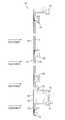
- FIG. 1is a side elevation view of a portion of a solar boiler constructed in accordance with the present invention, showing the receiver surface and the interior surface of the panel;
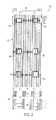
- FIG. 2is an interior elevation view of a portion of the solar boiler of FIG. 1 , showing the tubing of the panels as well as the headers;
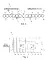
- FIG. 3is a cross-sectional view of a first exemplary embodiment of an expansion joint for solar boiler panels constructed in accordance with the present invention, showing the panel expansion shield spanning the gap between two adjacent boiler panels;
- FIG. 4is an interior elevation view of the expansion joint of FIG. 3 , showing the slotted holes for attaching the panel expansion shield to the panels while accommodating for vertical thermal expansion and contraction of the panels;
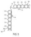
- FIG. 5is a cross-sectional view of a second exemplary embodiment of an expansion joint for solar boiler panels constructed in accordance with the present invention, showing how corner panels can be accommodated by a corner panel expansion shield;
- FIG. 6is a cross-sectional view of a third exemplary embodiment of an expansion joint constructed in accordance with the present invention, showing two plates that can slide over one another to allow for lateral thermal expansion;
- FIG. 7is a interior elevation view of the expansion joint of FIG. 6 , showing the alignment of the plates;
- FIG. 8is a cross-sectional view of a fourth exemplary embodiment of an expansion joint constructed in accordance with the present invention, showing how corner panels can be accommodated by a corner panel expansion shield;
- FIG. 9is an interior elevation view of the expansion joint of FIG. 8 , showing the expansion joint attached to corner panels of a boiler;
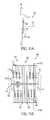
- FIG. 10is a partial cross-sectional view of a fifth exemplary embodiment of an expansion joint constructed in accordance with the present invention.
- FIGS. 11( a ) and 11 ( b )show how the fifth exemplary embodiment utilizes a T-bar assembly, where FIG. 11( a ) is a partial cross-sectional view of a T-bar assembly and FIG. 11( b ) is a top view of a T-bar assembly; and
- FIG. 12is an isolated top cross-sectional view of a corner assembly of the fifth exemplary embodiment.
- FIG. 1a partial view of a boiler in accordance with the invention is shown in FIG. 1 and is designated generally by reference character 100 .
- FIGS. 2-12Exemplary embodiments of a boiler in accordance with the invention, or aspects thereof, are provided in FIGS. 2-12 , as will be described.
- the systems of the inventioncan be used to more effectively accommodate vertical and lateral thermal expansion in boiler panels while limiting leakage of solar radiation, for example in solar power generation.
- a typical boileris split into panels, which are sized to facilitate manufacturing, shipping, and assembly. Due to the unique heat flux in solar applications, specifically the large variations in heat flux experienced over small areas, each panel must be allowed to thermally expand and grow independently from the adjacent panels. Typically, there is a gap to allow for such thermal expansion, however, leaving a gap between panels allows concentrated solar radiation to penetrate into the boiler, i.e. leakage, exposing equipment inside. To prevent this, the system in accordance with the present invention is configured to reduce or eliminate radiation leakage, while still allowing for thermal expansion, both vertically and horizontally.
- the systemconsists of a panel expansion shield constructed of steel or any suitable material, which is fastened through slotted holes therethrough to the adjacent tubes across a gap between panels.
- the slotted holeallows for varying vertical expansion between panels.
- the shielditself is designed to flex inward as the panels grow toward each other.
- a panel expansion shieldcan also be configured to prevent radiation leakage at corner panels, where two panels meet perpendicular to each other. By using a panel expansion shield corner panels are allowed to grow in two dimensions, while maintaining a barrier to concentrated solar radiation.
- boiler 100 for a solar receiverincludes a first boiler panel 102 , of a steam generator section for example, having a plurality of tubes fluidly connecting an inlet header of the first boiler (not shown, but see, e.g., 112 ) panel 102 to an outlet header 104 of the first boiler panel 102 .
- the tubes of first boiler panel 102form a first solar receiver surface 106 and a first internal surface 108 opposite first solar receiver surface 106 .
- the exterior receiver surface 106receives solar energy, for example from a field of heliostats, as indicated by arrows in FIG. 1 .
- a second boiler panel 110of a superheater section, for example, similarly includes a plurality of tubes fluidly connecting an inlet header 112 of second boiler panel 110 to an outlet header 114 of second boiler panel 110 .
- the tubes of second boiler panel 110forming a second solar receiver surface 116 and a second internal surface 118 opposite the second solar receiver surface (i.e. external and internal surfaces, respectively, as indicated in FIG. 1 ).
- exterior receiver surface 116receives solar energy, for example, from a field of heliostats, as indicated by arrows in FIG. 1 .
- First and second boiler panels 102 and 110are adjacent one another with an end 120 of first solar receiver surface 106 overlapping an end 122 of second boiler panel 110 to reduce solar radiation passing between the first and second solar receiver surfaces 106 and 116 .
- the interior surfaceshave a layer of insulating material 124 to protect the interior space and components from the high external temperatures.
- FIG. 2shows the same portion of boiler 100 from the interior, with insulating material 124 removed to show the tubes and headers.
- boiler 100includes a first receiver panel 110 a having a plurality of substantially parallel boiler tubes 210 fluidly connecting an inlet header of the panel 110 a to an outlet header of the panel, as described above.
- a second receiver panel 110 bhas a plurality of substantially parallel boiler tubes 210 fluidly connecting an inlet header of the panel to an outlet header of the panel 110 b , as described above.
- the boiler tubes 210 of second receiver panel 110 bare substantially parallel to the boiler tubes 210 of first receiver panel 110 a .
- the first and second receiver panels 110 a,bare separated by a gap 11 .
- a panel expansion shield 10is connected to the first and second receiver panels 110 a,b across gap 11 .
- Panel expansion shieldincludes a bend 12 which can flex to allow for lateral (width-wise) thermal expansion and contraction of the receiver panels toward and away from one another, as indicated by arrows in FIG. 3 .
- Panel expansion shield 10runs vertically along substantially the entire length of panels 110 a,b to block solar radiation through gap 11 .
- Panel expansion shield 10is also configured and adapted to allow for vertical thermal expansion and contraction of the receiver panels along the lengthwise direction boiler tubes 210 , as indicated by arrows in FIG. 4 .
- panel expansion shield 10has elongated slots 16 and is attached to first and second receiver panels 110 a,b by fasteners 14 passing through elongated slots 16 to accommodate vertical thermal expansion of panels 110 a,b and to allow for differences in thermal expansion.
- first and second receiver panels 110 a,bare substantially coplanar with each other. As indicated in FIG. 5 , in a second exemplary embodiment, it is also contemplated that first and second receiver panels 110 a,b can be substantially perpendicular to one another, as at a corner of a solar boiler, for example.
- Panel expansion shield 20is configured to prevent radiation leakage at the corners of the boiler.
- Panel expansion shield 20consists of a single bent steel plate.
- any suitable materialcan be used without departing from the spirit and scope of the invention.
- Panel expansion shield 20accommodates vertical movement of panels 110 a,b in the same manner as panel expansion shield 10 , that is, by vertical slot attachments for fasteners 14 . While shown and described as accommodating a right angle, those skilled in the art will readily appreciate that panel expansion shields can be configured to accommodate any suitable angle without departing from the spirit and scope of the invention.
- panel expansion shields 10 and 20are made of steel, ceramics, or any other suitable material.
- Rods 215are used to attach tubes 210 together, as indicated in FIG. 3 . This prevents leakage between tubes, provides support for the tubes, and allows for the tubes to flex as in thermal expansion and contraction. Rods 215 allow tubes 210 to be closer together (i.e., tangent), increasing the effective solar receiver area compared to panels with membranes between the tubes.
- FIGS. 6-7show a cross-sectional and interior elevation view, respectively, of another exemplary expansion shield 30 in accordance a third exemplary embodiment of the present invention.
- Expansion shield 30includes a first plate 32 a fastened to one panel and a second plate 32 b fastened to an adjacent panel.
- Plate 32 aincludes an overlap plate 33 .
- Plates 32 a and 32 bslide over one another to allow for lateral and vertical thermal expansion.
- FIGS. 8-9show cross-sectional and interior elevation views, respectively, of a fourth exemplary embodiment showing a corner expansion shield 40 in accordance with the invention.
- Corner expansion shield 40operates much the same as corner expansion shield 20 described above, with a different cross-sectional shape that keeps the bend of the shield more to the interior of the boiler.
- Those skilled in the artwill readily appreciate that any suitable cross-sectional shape can be used without departing from the spirit and scope of the invention.
- FIGS. 10 , 11 ( a ) and 11 ( b )show a fifth exemplary embodiment of the present invention.
- Panels 110 a and 110 bare arranged in-line and parallel to one another with a gap 550 between the panels.
- Lower tube clips 514are welded to boiler tubes 210 , as shown in FIG. 11( a ).
- a stainless steel plate 506is inserted into lower tube clips 514 , resting on its lower edge.
- Each panel 110 a and 110 bhas an individual stainless steel plate 506 which runs the width of each panel, i.e., substantially perpendicular to the tubes.
- a back steel support plate 510is inserted behind stainless steel plate 506 into lower tube clips 514 .
- back support steel plate 510rests on the lower tube clips 514 and runs the width of each panel 110 a and 110 b .
- Upper tube clips 515are then welded to tubes 210 , holding stainless steel plate 506 and back support steel plate 510 in place.
- Stainless steel plate 506serves to protect the support assembly 540 from penetrating solar radiation.
- T-bar 518is then welded perpendicular to back steel support 510 to create a rigid strong back.
- Assembly 540serves to hold each boiler tube 210 from bowing outward.
- Connecting plate 522connects adjoining T-bars 518 .
- Bolt 526secures connecting plate 522 to adjoining T-bars 518 .
- Connecting slot 530allows bolt 526 to move horizontally, which allows panels 110 a and 110 b to expand towards each other freely.
- two boiler tubes 210are held out-of-plane by membrane 502 .
- the out-of-plane tubes 210serve to protect the panel gap 550 from penetrating solar radiation. As the boiler 100 heats up during operation, panels 110 a and 110 b grow together to close gap 550 .
Landscapes
- Engineering & Computer Science (AREA)
- Physics & Mathematics (AREA)
- Life Sciences & Earth Sciences (AREA)
- Sustainable Development (AREA)
- Sustainable Energy (AREA)
- Thermal Sciences (AREA)
- Chemical & Material Sciences (AREA)
- Combustion & Propulsion (AREA)
- Mechanical Engineering (AREA)
- General Engineering & Computer Science (AREA)
- Photovoltaic Devices (AREA)
Abstract
Description
Claims (10)
Priority Applications (8)
| Application Number | Priority Date | Filing Date | Title |
|---|---|---|---|
| US12/701,999US8893714B2 (en) | 2009-02-12 | 2010-02-08 | Expansion joints for panels in solar boilers |
| ES201190057AES2411812B1 (en) | 2009-02-12 | 2010-02-09 | EXPANSION JOINTS FOR PANELS IN SOLDER BOILERS |
| PCT/US2010/023622WO2010093625A2 (en) | 2009-02-12 | 2010-02-09 | Expansion joints for panels in solar boilers |
| AU2010213890AAU2010213890C1 (en) | 2009-02-12 | 2010-02-09 | Expansion joints for panels in solar boilers |
| IL214524AIL214524A (en) | 2009-02-12 | 2011-08-08 | Expansion joints for panels in solar boilers |
| US14/500,410US20150027437A1 (en) | 2009-02-12 | 2014-09-29 | Expansion joints for panels in solar boilers |
| IL238012AIL238012A0 (en) | 2009-02-12 | 2015-03-29 | Expansion joints for panels in solar boilers |
| IL239012AIL239012A0 (en) | 2009-02-12 | 2015-05-26 | Expansion joints for panels in solar boilers |
Applications Claiming Priority (8)
| Application Number | Priority Date | Filing Date | Title |
|---|---|---|---|
| US15198409P | 2009-02-12 | 2009-02-12 | |
| US15211409P | 2009-02-12 | 2009-02-12 | |
| US15203509P | 2009-02-12 | 2009-02-12 | |
| US15204909P | 2009-02-12 | 2009-02-12 | |
| US15201109P | 2009-02-12 | 2009-02-12 | |
| US15207709P | 2009-02-12 | 2009-02-12 | |
| US15228609P | 2009-02-13 | 2009-02-13 | |
| US12/701,999US8893714B2 (en) | 2009-02-12 | 2010-02-08 | Expansion joints for panels in solar boilers |
Related Child Applications (1)
| Application Number | Title | Priority Date | Filing Date |
|---|---|---|---|
| US14/500,410DivisionUS20150027437A1 (en) | 2009-02-12 | 2014-09-29 | Expansion joints for panels in solar boilers |
Publications (2)
| Publication Number | Publication Date |
|---|---|
| US20100199980A1 US20100199980A1 (en) | 2010-08-12 |
| US8893714B2true US8893714B2 (en) | 2014-11-25 |
Family
ID=47263787
Family Applications (2)
| Application Number | Title | Priority Date | Filing Date |
|---|---|---|---|
| US12/701,999Expired - Fee RelatedUS8893714B2 (en) | 2009-02-12 | 2010-02-08 | Expansion joints for panels in solar boilers |
| US14/500,410AbandonedUS20150027437A1 (en) | 2009-02-12 | 2014-09-29 | Expansion joints for panels in solar boilers |
Family Applications After (1)
| Application Number | Title | Priority Date | Filing Date |
|---|---|---|---|
| US14/500,410AbandonedUS20150027437A1 (en) | 2009-02-12 | 2014-09-29 | Expansion joints for panels in solar boilers |
Country Status (5)
| Country | Link |
|---|---|
| US (2) | US8893714B2 (en) |
| AU (1) | AU2010213890C1 (en) |
| ES (1) | ES2411812B1 (en) |
| IL (3) | IL214524A (en) |
| WO (1) | WO2010093625A2 (en) |
Cited By (7)
| Publication number | Priority date | Publication date | Assignee | Title |
|---|---|---|---|---|
| US20140290248A1 (en)* | 2011-12-22 | 2014-10-02 | Mitshubhish Heavy Industries, Ltd | Solar heat receiver, method for assembling same, and solar heat power generation system with solar heat receiver |
| US10644282B2 (en) | 2018-01-23 | 2020-05-05 | Nio Usa, Inc. | Staggered battery cell array with two-dimensional inline terminal edges |
| US10707471B2 (en) | 2018-03-22 | 2020-07-07 | Nio Usa, Inc. | Single side cell-to-cell battery module interconnection |
| US10741889B2 (en) | 2018-03-22 | 2020-08-11 | Nio Usa, Inc. | Multiple-zone thermocouple battery module temperature monitoring system |
| US10741808B2 (en) | 2018-03-15 | 2020-08-11 | Nio Usa, Inc. | Unified battery module with integrated battery cell structural support |
| US10784486B2 (en) | 2018-02-20 | 2020-09-22 | Nio Usa, Inc. | Uniform current density tapered busbar |
| US10892465B2 (en) | 2018-03-22 | 2021-01-12 | Nio Usa, Inc. | Battery cell cover including terminal short isolation feature |
Families Citing this family (11)
| Publication number | Priority date | Publication date | Assignee | Title |
|---|---|---|---|---|
| US8490618B2 (en)* | 2007-07-26 | 2013-07-23 | Brightsource Industries (Israel) Ltd. | Solar receiver |
| WO2012073664A1 (en)* | 2010-12-01 | 2012-06-07 | 株式会社日立プラントテクノロジー | Solar thermal collector tube |
| MX2011002035A (en) | 2011-02-11 | 2012-08-30 | Fricaeco America S A De C V | Solar liquid heater. |
| US9638440B2 (en)* | 2012-11-13 | 2017-05-02 | Alstom Technology Ltd. | Solar boiler panel arrangement |
| US9341392B2 (en)* | 2012-11-13 | 2016-05-17 | Alstom Technology Ltd. | Solar receiver panel and support structure |
| GB201402698D0 (en)* | 2014-02-16 | 2014-04-02 | Ruff Brendan P | Modular double glazed long narrow solar collector and mounting means |
| US8936020B1 (en)* | 2014-03-12 | 2015-01-20 | Fricaeco America Sapi De C.V. | Solar fluids preheating system with low thermal losses |
| BE1022075B1 (en)* | 2014-05-14 | 2016-02-15 | Cockerill Maintenance & Ingenierie S.A. | SOLAR TOWER WITH CONCENTRATION WITH EXTERNAL RECEIVER |
| BE1022536B1 (en) | 2014-10-28 | 2016-05-25 | Cockerill Maintenance & Ingenierie Sa | SEALED STRUCTURE FOR EXTERNAL SOLAR RECEIVER IN A TOWER OF A CONCENTRATION SOLAR POWER PLANT |
| US9534811B2 (en) | 2014-12-31 | 2017-01-03 | Fricaeco America, SAPI de C.V. | Solar fluid preheating system having a thermosiphonic aperture and concentrating and accelerating convective nanolenses |
| MX2020005013A (en)* | 2017-11-15 | 2020-10-05 | Vast Solar Pty Ltd | A concentrated solar power receiver. |
Citations (153)
| Publication number | Priority date | Publication date | Assignee | Title |
|---|---|---|---|---|
| US2383234A (en) | 1942-04-29 | 1945-08-21 | Barnes William Speight | Solar water still |
| US3163265A (en)* | 1963-04-01 | 1964-12-29 | Transco Inc | Insulating panels for boilers and the like |
| US3197343A (en) | 1962-07-05 | 1965-07-27 | Carrier Corp | Thermoelectric panels |
| US3208877A (en) | 1962-06-14 | 1965-09-28 | Carrier Corp | Thermoelectric panels |
| US3325312A (en) | 1962-06-14 | 1967-06-13 | Carrier Corp | Thermoelectric panels |
| US3450192A (en) | 1967-01-20 | 1969-06-17 | Harold R Hay | Process and apparatus for modulating the temperature within enclosures |
| US3459597A (en) | 1966-02-04 | 1969-08-05 | Trw Inc | Solar cells with flexible overlapping bifurcated connector |
| US3464402A (en) | 1967-09-21 | 1969-09-02 | Frank Collura | Solar heat exchanger construction |
| US3814530A (en)* | 1972-02-18 | 1974-06-04 | Felt Products Mfg Co | Method of sealing a curb and gutter roadway gap and sealing assembly therefor |
| US3822692A (en) | 1973-05-25 | 1974-07-09 | J Demarest | Controlled solar energized power generator |
| US3823703A (en) | 1971-10-21 | 1974-07-16 | J Lanciault | Self-storing solar heater |
| US3893506A (en) | 1971-09-17 | 1975-07-08 | Nikolaus Laing | Device for the absorption and emission of heat |
| US3924604A (en) | 1974-05-31 | 1975-12-09 | Schjeldahl Co G T | Solar energy conversion system |
| US3927659A (en) | 1973-09-21 | 1975-12-23 | Martin Marietta Corp | Peak efficiency solar energy powered boiler and superheater |
| US3951108A (en) | 1974-04-29 | 1976-04-20 | Sulzer Brothers Limited | Means for supporting a displaceable mass on a stationary frame |
| US3968652A (en) | 1975-06-09 | 1976-07-13 | Chevalier Donald M | Apparatus responsive to solar energy for producing power |
| US3991742A (en) | 1975-01-09 | 1976-11-16 | Burke Industries, Inc. | Solar energy heat transfer system |
| US3995804A (en) | 1975-08-15 | 1976-12-07 | Larry J. Folds | Inverted open channel solar heat collector panel |
| US4003366A (en) | 1975-12-11 | 1977-01-18 | Lightfoot Daniel J | Solar heat collector module |
| US4037639A (en) | 1976-11-08 | 1977-07-26 | Jones J Paul | Thermal barrier |
| US4088266A (en) | 1976-06-24 | 1978-05-09 | International Solarthermics Corporation | Method and apparatus for collecting, storing and transmitting solar heat |
| US4094147A (en) | 1976-03-11 | 1978-06-13 | Commissariat A L'energie Atomique | Circuit for the supply of condensable fluid to a solar engine |
| US4112921A (en) | 1977-04-25 | 1978-09-12 | Calmac Manufacturing Corporation | Method and system for utilizing a flexible tubing solar collector |
| US4120288A (en) | 1977-01-21 | 1978-10-17 | Columbia Chase Corporation | Solar collector |
| JPS53131309A (en) | 1977-04-22 | 1978-11-16 | Hitachi Ltd | Fixing arrangement for an expansion joint |
| US4127102A (en) | 1977-05-16 | 1978-11-28 | Berman Mark H | Heat absorbing window |
| US4127103A (en) | 1976-12-21 | 1978-11-28 | Klank Benno E O | Heat collecting and transferring apparatus and systems adapted for use with solar energy |
| US4128096A (en) | 1975-08-13 | 1978-12-05 | Solly Katz | Solar heaters |
| US4136674A (en) | 1977-07-28 | 1979-01-30 | A. L. Korr Associates, Inc. | System for solar radiation energy collection and conversion |
| US4191246A (en) | 1979-03-05 | 1980-03-04 | Combustion Engineering, Inc. | Device to reduce local heat flux through a heat exchanger tube |
| US4204523A (en) | 1976-09-11 | 1980-05-27 | E. Cacarda Gmbh | Mount for solar collectors |
| US4205658A (en) | 1977-10-06 | 1980-06-03 | Clark Peter C | Heat transfer panel |
| US4210122A (en) | 1976-08-11 | 1980-07-01 | Artweger-Industrie-Gesellschaft M.B.H. | Energy conversion apparatus |
| US4215676A (en) | 1978-10-11 | 1980-08-05 | Gilliam George A | Frame arms for solar collector |
| US4237861A (en) | 1978-05-05 | 1980-12-09 | Fayard Carlos A | Solar energy collector used as roof member |
| US4245618A (en) | 1978-10-10 | 1981-01-20 | The Babcock & Wilcox Co. | Vapor generator |
| US4253801A (en) | 1977-06-09 | 1981-03-03 | Hare Louis R O | Convection current pumping called, series convection pump |
| US4257477A (en) | 1978-09-12 | 1981-03-24 | One Design, Inc. | Environmentally driven heating and cooling system |
| US4261330A (en) | 1979-03-07 | 1981-04-14 | Reinisch Ronald F | Solar heat collector |
| US4265223A (en) | 1978-09-18 | 1981-05-05 | The Badger Company, Inc. | Method and apparatus for utilizing solar energy |
| US4269172A (en) | 1976-11-08 | 1981-05-26 | Parker Peter D | Solar water-heating apparatus |
| US4273100A (en) | 1979-02-16 | 1981-06-16 | W. R. Grace & Co. | Passive solar heating and cooling panels |
| US4280483A (en) | 1980-09-11 | 1981-07-28 | Schaffer I Lawrence | Solar heater |
| US4289114A (en) | 1978-09-12 | 1981-09-15 | The Babcock & Wilcox Company | Control system for a solar steam generator |
| US4296730A (en) | 1978-09-12 | 1981-10-27 | The Babcock & Wilcox Company | Control system for a solar steam generator |
| US4296733A (en) | 1976-08-05 | 1981-10-27 | Saunders Norman B | Heating, lighting and ventilation systems |
| US4312687A (en) | 1980-12-15 | 1982-01-26 | Chevron Research Company | Solar collector headers |
| US4313304A (en) | 1979-07-26 | 1982-02-02 | The United States Of America As Represented By The United States Department Of Energy | Radiant energy collection and conversion apparatus and method |
| US4320663A (en) | 1979-05-17 | 1982-03-23 | Giovanni Francia | Control system and method for controlling a solar energy plant |
| US4324229A (en) | 1977-11-28 | 1982-04-13 | Risser James A | Solar collector and heat and cold generator |
| US4338991A (en) | 1980-04-28 | 1982-07-13 | Sigworth Jr Harrison W | Combined solar heating and passive cooling apparatus |
| FR2501839A1 (en) | 1981-03-13 | 1982-09-17 | Hdg Ind Solaire Tuile Solaire | Window shutter incorporating solar panel - has protective insulating cover on rear face of panel hinged to window frame |
| US4350374A (en) | 1978-10-04 | 1982-09-21 | Industrie Pirelli S.P.A. | Header for solar-panels and a device for connecting header to panel |
| US4353356A (en) | 1979-07-03 | 1982-10-12 | Sealed Air Corporation | Solar collector units with mounting frame |
| US4359043A (en) | 1979-04-27 | 1982-11-16 | Gazel Dominique | Roofing member for collecting solar energy |
| US4367726A (en) | 1979-02-22 | 1983-01-11 | Environmental Research Institute Of Michigan | Solar hot water heater |
| US4371035A (en) | 1978-05-17 | 1983-02-01 | Vincenzo Soligno | Tube support grid |
| US4373512A (en) | 1980-02-08 | 1983-02-15 | Maschinenfabrik Augsburg-Nurnberg Aktiengesellschaft | Method and apparatus for protecting an arrangement located in an area of highly concentrated radiation |
| US4380996A (en) | 1978-04-08 | 1983-04-26 | Mero-Raumstruktur Gmbh & Co. | Roof construction for buildings |
| US4384550A (en) | 1980-12-19 | 1983-05-24 | Rockwell International Corporation | Thermal receiver |
| US4394859A (en) | 1981-10-27 | 1983-07-26 | The United States Of America As Represented By The United States Department Of Energy | Central solar energy receiver |
| US4404960A (en) | 1979-04-17 | 1983-09-20 | Karsten Laing | Roof skin forming a heat sink |
| US4416265A (en) | 1981-12-16 | 1983-11-22 | Wallace John G | Solar collector |
| US4428361A (en) | 1976-06-11 | 1984-01-31 | Straza George T | Solar heating shingle roof structure |
| US4432341A (en) | 1982-05-06 | 1984-02-21 | Future Tech, Inc. | Solar heater and roof attachment means |
| US4454863A (en) | 1976-08-30 | 1984-06-19 | Brown Donald P | Solar heat collecting panel assembly and method for covering structures |
| US4485803A (en)* | 1982-10-14 | 1984-12-04 | The Babcock & Wilcox Company | Solar receiver with interspersed panels |
| US4503903A (en) | 1982-07-06 | 1985-03-12 | Westinghouse Electric Corp. | Heat exchanger tube sheet radial support |
| US4512336A (en) | 1982-10-14 | 1985-04-23 | The Babcock & Wilcox Company | Panel of vapor generating and superheating tubes |
| US4535755A (en) | 1983-03-04 | 1985-08-20 | Roberts Griffith T | Solar energy collector |
| US4569331A (en) | 1982-12-10 | 1986-02-11 | Tokyo Shibaura Denki Kabushiki Kaisha | Solar heat powered plant |
| US4615381A (en) | 1982-07-30 | 1986-10-07 | One Design, Inc. | Solar heating and cooling diode module |
| US4653470A (en) | 1985-12-20 | 1987-03-31 | Foster Wheeler Development Corp. | Support structure for solar receiver panel tubes |
| US4660630A (en) | 1985-06-12 | 1987-04-28 | Wolverine Tube, Inc. | Heat transfer tube having internal ridges, and method of making same |
| US4665894A (en) | 1982-05-18 | 1987-05-19 | Kozponti Valto-Es Hitelbank Rt. Innovacios Alap | Gas-heated or kerosene-heated boiler for warm water, hot water or steam generation |
| US4712338A (en) | 1986-06-30 | 1987-12-15 | Trickel Lorn L | Solar-energy-collecting structural unit and solar roof |
| US4721069A (en)* | 1987-06-19 | 1988-01-26 | The Babcock & Wilcox Company | Termination for boiler casing expansion element |
| US4768345A (en) | 1986-10-03 | 1988-09-06 | Institute Of Gas Technology | Continuous thermal energy delivery from a periodically active energy source |
| US4832119A (en) | 1986-06-05 | 1989-05-23 | Bloor Trevor J | Multi-tube heat exchanger and connectors therefor |
| US4867133A (en) | 1986-03-26 | 1989-09-19 | Charlton Sadler | Solar collector method and apparatus |
| US4946512A (en) | 1988-03-28 | 1990-08-07 | Yoshida Kogyo K. K. | Solar energy collector device |
| US4972806A (en) | 1988-12-08 | 1990-11-27 | Societe Anonyme Dite: Stein Industrie | Device enabling a mass cantilevered from a vertically moveable element to rest against a fixed framework |
| US5163821A (en) | 1991-04-02 | 1992-11-17 | Worldwater, Inc. | Solar thermal powered water pump |
| US5174128A (en) | 1991-05-13 | 1992-12-29 | Davis Energy Group, Inc. | Energy-saving protected roof systems |
| US5201282A (en) | 1989-10-17 | 1993-04-13 | The Babcock & Wilcox Company | Upflow/downflow heated tube circulating system |
| US5217000A (en) | 1988-02-23 | 1993-06-08 | Pierce Bjorklund Patricia | Compound solar collector building construction |
| US5342016A (en) | 1991-12-23 | 1994-08-30 | Stein Industrie | Device for supporting, on a fixed framework, a mass which is cantilevered out from a moving element |
| US5368092A (en) | 1993-12-27 | 1994-11-29 | Biotherm Hydronic, Inc. | Apparatus and method for controlling temperature of a turf field |
| US5404937A (en) | 1987-12-04 | 1995-04-11 | Solmat Systems Ltd. | Method of and apparatus for producing power from solar ponds |
| US5417052A (en) | 1993-11-05 | 1995-05-23 | Midwest Research Institute | Hybrid solar central receiver for combined cycle power plant |
| US5444972A (en) | 1994-04-12 | 1995-08-29 | Rockwell International Corporation | Solar-gas combined cycle electrical generating system |
| US5482233A (en) | 1994-02-28 | 1996-01-09 | Rockwell International Corporation | Dismountable, slidable tube support clip for accommodating high-temperature thermal expansion |
| JPH08326223A (en) | 1995-05-29 | 1996-12-10 | Yane Gijutsu Kenkyusho:Kk | Roofing material |
| US5694774A (en) | 1996-02-29 | 1997-12-09 | Drucker; Ernest R. | Solar energy powerplant |
| US5727379A (en) | 1996-05-31 | 1998-03-17 | Electric Power Research Institute | Hybid solar and fuel fired electrical generating system |
| US5823176A (en) | 1997-11-10 | 1998-10-20 | Harris; Don | Solar water heating panel attachment device |
| US5850831A (en) | 1996-09-27 | 1998-12-22 | Boeing North American, Inc. | Loose-tight-loose twist, twisted-tape insert solar central receiver |
| US5857322A (en) | 1997-09-30 | 1999-01-12 | Electric Power Research Institute, Inc. | Hybrid solar and fuel fired electrical generating system |
| US5862800A (en) | 1996-09-27 | 1999-01-26 | Boeing North American, Inc. | Molten nitrate salt solar central receiver of low cycle fatigue 625 alloy |
| US5881456A (en) | 1997-03-20 | 1999-03-16 | Arup Alu-Rohr Und Profil Gmbh | Header tubes for heat exchangers and the methods used for their manufacture |
| US5943985A (en) | 1996-12-23 | 1999-08-31 | Hartman; Ernest L. | Welded bracket for supporting superheat and reheat assembly tubing on steam cooled hanger tubes |
| US6126120A (en) | 1998-06-18 | 2000-10-03 | Alstom France S.A. | Suspension cradle for supporting a hanging heat exchanger |
| US6155339A (en) | 1999-06-18 | 2000-12-05 | Grapengater; Richard B. | Obround header for a heat exchanger |
| US6173927B1 (en) | 1998-06-18 | 2001-01-16 | Alston France S.A. | Device for suspending a horizontal heat-exchanger tube from a vertical supporting tube |
| US6240156B1 (en) | 1997-08-29 | 2001-05-29 | General Electric Company | Top guide grid attachment for a boiling water reactor |
| US20010010222A1 (en) | 1999-05-18 | 2001-08-02 | Prueitt Melvin L. | Solar power generation and energy storage system |
| US6301928B1 (en) | 1999-04-15 | 2001-10-16 | The Director-General Of The Institute Of Space And Astronautical Science | Method for improving the performance of a cryogenic heat exchanger under frosting conditions |
| US20020029869A1 (en) | 1998-11-10 | 2002-03-14 | Kodumudi Magesh V. | Side member for heat exchanger and heat exchanger incorporating side plate |
| US6434942B1 (en) | 2001-09-20 | 2002-08-20 | Walter T. Charlton | Building, or other self-supporting structure, incorporating multi-stage system for energy generation |
| US6487859B2 (en) | 2000-08-03 | 2002-12-03 | Midwest Research Institute | Dish/stirling hybrid-receiver |
| US6497102B2 (en) | 1999-12-23 | 2002-12-24 | Alstom (Switzerland) Ltd | Method for supplementing a saturated steam generation system having at least one steam turbine set, and steam power plant supplemented using the method |
| US20030041856A1 (en) | 2001-08-30 | 2003-03-06 | Blackmon James B. | Geometric dome stowable tower reflector |
| US6668555B1 (en) | 2002-12-09 | 2003-12-30 | The Boeing Company | Solar receiver-based power generation system |
| US20040035111A1 (en) | 2000-09-19 | 2004-02-26 | Ven Livien Domien | Method and device for producing steam by means of solar energy |
| US6708687B2 (en) | 2001-06-12 | 2004-03-23 | James B. Blackmon, Jr. | Thermally controlled solar reflector facet with heat recovery |
| US6736134B2 (en) | 2001-09-05 | 2004-05-18 | The Boeing Company | Thin wall header for use in molten salt solar absorption panels |
| US20040112374A1 (en) | 2002-12-13 | 2004-06-17 | Litwin Robert Z. | Solar central receiver with inboard headers |
| US20040244376A1 (en) | 2003-06-03 | 2004-12-09 | Litwin Robert Z. | Systems and methods for generating electrical power from solar energy |
| US20040251002A1 (en) | 2002-04-09 | 2004-12-16 | Frank Reichle | Heat transfer unit, especially for a motor vehicle |
| US20040256000A1 (en)* | 2003-06-20 | 2004-12-23 | Moshe Konstantin | Dual panel system for controlling the passage of light through architectural structures |
| US20040255571A1 (en) | 2000-01-13 | 2004-12-23 | Alstom (Switzerland) Ltd. | Cooling-air cooler for a gas-turbine plant and use of such a cooling-air cooler |
| US20050016524A1 (en) | 2003-06-19 | 2005-01-27 | Broatch Peter Martin | Solar heat absorber panels |
| US6913015B2 (en) | 2001-05-08 | 2005-07-05 | Aljosa Pajk | Modular system for utilization of solar energy for heating of sanitary water |
| US6926440B2 (en) | 2002-11-01 | 2005-08-09 | The Boeing Company | Infrared temperature sensors for solar panel |
| US7011086B2 (en) | 2002-12-05 | 2006-03-14 | The Boeing Company | Bottom supported solar receiver panel apparatus and method |
| US20060225863A1 (en) | 2005-04-12 | 2006-10-12 | Alexander Levin | Heat and cold storage multistage tower with application of PCM |
| US20060260314A1 (en) | 2005-03-25 | 2006-11-23 | Kincaid Ronald F | Method and system integrating combined cycle power plant with a solar rankine power plant |
| US20070089775A1 (en) | 2003-08-29 | 2007-04-26 | Lasich John B | Extracting heat from an object |
| US20070119718A1 (en) | 2004-02-18 | 2007-05-31 | Gm Global Technology Operations, Inc. | Optimizing photovoltaic-electrolyzer efficiency |
| US20070227531A1 (en) | 2005-04-07 | 2007-10-04 | Josep Garcia Cors | Modular solar energy-collecting enclosure element, and modular system for forming solar energy-collecting enclosures on buildings |
| US20070295382A1 (en) | 2006-06-23 | 2007-12-27 | Eugene Oak | Solar super structure with cooling system |
| US20080000231A1 (en) | 2006-06-30 | 2008-01-03 | United Technologies Corporation | High temperature molten salt receiver |
| US20080022685A1 (en) | 2006-07-25 | 2008-01-31 | Yanong Zhu | Concentrate solar thermal energy electric power plant logic boiler |
| US20080053523A1 (en)* | 2006-08-30 | 2008-03-06 | Brown Acie | Solar cell interconnect |
| US20080078378A1 (en) | 2006-07-25 | 2008-04-03 | Yanong Zhu | Method and apparatus of solar central receiver with boiler and super-heater |
| US20080092551A1 (en) | 2006-10-18 | 2008-04-24 | Mark Joseph Skowronski | Method and system integrating combustion turbine with a regenerative solar rankine power plant |
| US20080256953A1 (en) | 2004-11-23 | 2008-10-23 | Evangelos Arkas | Solar Energy Trap and Turbine |
| US20080302357A1 (en) | 2007-06-05 | 2008-12-11 | Denault Roger | Solar photovoltaic collector hybrid |
| WO2008154599A1 (en) | 2007-06-11 | 2008-12-18 | Brightsource Energy, Inc. | Solar receiver |
| US20090014057A1 (en) | 2007-07-13 | 2009-01-15 | Miasole | Photovoltaic modules with integrated devices |
| US20090101134A1 (en) | 2007-10-17 | 2009-04-23 | Stephen Lawrence Merrett | Solar panel |
| US20090107146A1 (en) | 2007-10-31 | 2009-04-30 | Wen Chang Lin | Solar energy power generator |
| US20090114269A1 (en) | 2007-11-07 | 2009-05-07 | Anne Elizabeth Fletcher | Quick release mechanism for solar panels |
| US20090114270A1 (en) | 2007-07-20 | 2009-05-07 | Robert Stancel | Rapid Mounting System for Solar Modules |
| US20090199557A1 (en) | 2008-02-12 | 2009-08-13 | Lawrence Livermore National Security, Llc | Solar Thermal Power System |
| US20090250051A1 (en) | 2006-02-01 | 2009-10-08 | Sener, Ingenieria Y Sistemas, S.A. | Thin wall header with a variable cross-section for solar absorption panels |
| US7600350B2 (en) | 2006-09-21 | 2009-10-13 | Ykk Corporation Of America | Thermally broken sunshade anchors |
| US20090260359A1 (en) | 2008-04-16 | 2009-10-22 | Alstom Technology Ltd. | Solar thermal power plant |
| US20090276993A1 (en) | 2008-05-07 | 2009-11-12 | Fedock Dennis S | Erection method for solar receiver & support tower |
| US7640746B2 (en) | 2005-05-27 | 2010-01-05 | Markon Technologies, LLC | Method and system integrating solar heat into a regenerative rankine steam cycle |
| US20100229853A1 (en) | 2009-01-13 | 2010-09-16 | Vandal Robert A | Mounting brackets for mirrors, and associated methods |
| US20100236183A1 (en) | 2009-03-20 | 2010-09-23 | Northern States Metals Company | Support System for Solar Panels |
| US7806377B2 (en) | 2008-02-25 | 2010-10-05 | Renewable Energy Holdings, Llc | Modular solar panel mounting system |
Family Cites Families (5)
| Publication number | Priority date | Publication date | Assignee | Title |
|---|---|---|---|---|
| US3007455A (en)* | 1958-01-03 | 1961-11-07 | Babcock & Wilcox Co | Vapor generator wall and buckstay arrangement |
| DE1926187A1 (en)* | 1969-05-22 | 1970-11-26 | Schoell Dr Ing Guenter | Heat exchange element made of materials with low thermal conductivity and strength |
| US5207184A (en)* | 1992-04-03 | 1993-05-04 | The Babcock & Wilcox Company | Boiler buckstay system for membranded tube wall end connection |
| ES2272194A1 (en)* | 2006-08-28 | 2007-04-16 | Universidad Politecnica De Madrid | Solar-powered boiler |
| WO2009105689A2 (en)* | 2008-02-22 | 2009-08-27 | Esolar, Inc. | Solar receivers with internal reflections and flux-limiting patterns of reflectivity |
- 2010
- 2010-02-08USUS12/701,999patent/US8893714B2/ennot_activeExpired - Fee Related
- 2010-02-09AUAU2010213890Apatent/AU2010213890C1/ennot_activeCeased
- 2010-02-09ESES201190057Apatent/ES2411812B1/enactiveActive
- 2010-02-09WOPCT/US2010/023622patent/WO2010093625A2/enactiveApplication Filing
- 2011
- 2011-08-08ILIL214524Apatent/IL214524A/enactiveIP Right Grant
- 2014
- 2014-09-29USUS14/500,410patent/US20150027437A1/ennot_activeAbandoned
- 2015
- 2015-03-29ILIL238012Apatent/IL238012A0/enunknown
- 2015-05-26ILIL239012Apatent/IL239012A0/enunknown
Patent Citations (157)
| Publication number | Priority date | Publication date | Assignee | Title |
|---|---|---|---|---|
| US2383234A (en) | 1942-04-29 | 1945-08-21 | Barnes William Speight | Solar water still |
| US3208877A (en) | 1962-06-14 | 1965-09-28 | Carrier Corp | Thermoelectric panels |
| US3325312A (en) | 1962-06-14 | 1967-06-13 | Carrier Corp | Thermoelectric panels |
| US3197343A (en) | 1962-07-05 | 1965-07-27 | Carrier Corp | Thermoelectric panels |
| US3163265A (en)* | 1963-04-01 | 1964-12-29 | Transco Inc | Insulating panels for boilers and the like |
| US3459597A (en) | 1966-02-04 | 1969-08-05 | Trw Inc | Solar cells with flexible overlapping bifurcated connector |
| US3450192A (en) | 1967-01-20 | 1969-06-17 | Harold R Hay | Process and apparatus for modulating the temperature within enclosures |
| US3464402A (en) | 1967-09-21 | 1969-09-02 | Frank Collura | Solar heat exchanger construction |
| US3893506A (en) | 1971-09-17 | 1975-07-08 | Nikolaus Laing | Device for the absorption and emission of heat |
| US3823703A (en) | 1971-10-21 | 1974-07-16 | J Lanciault | Self-storing solar heater |
| US3814530A (en)* | 1972-02-18 | 1974-06-04 | Felt Products Mfg Co | Method of sealing a curb and gutter roadway gap and sealing assembly therefor |
| US3822692A (en) | 1973-05-25 | 1974-07-09 | J Demarest | Controlled solar energized power generator |
| US3927659A (en) | 1973-09-21 | 1975-12-23 | Martin Marietta Corp | Peak efficiency solar energy powered boiler and superheater |
| US3951108A (en) | 1974-04-29 | 1976-04-20 | Sulzer Brothers Limited | Means for supporting a displaceable mass on a stationary frame |
| US3924604A (en) | 1974-05-31 | 1975-12-09 | Schjeldahl Co G T | Solar energy conversion system |
| US3991742A (en) | 1975-01-09 | 1976-11-16 | Burke Industries, Inc. | Solar energy heat transfer system |
| US3968652A (en) | 1975-06-09 | 1976-07-13 | Chevalier Donald M | Apparatus responsive to solar energy for producing power |
| US4128096A (en) | 1975-08-13 | 1978-12-05 | Solly Katz | Solar heaters |
| US3995804A (en) | 1975-08-15 | 1976-12-07 | Larry J. Folds | Inverted open channel solar heat collector panel |
| US4003366A (en) | 1975-12-11 | 1977-01-18 | Lightfoot Daniel J | Solar heat collector module |
| US4094147A (en) | 1976-03-11 | 1978-06-13 | Commissariat A L'energie Atomique | Circuit for the supply of condensable fluid to a solar engine |
| US4428361A (en) | 1976-06-11 | 1984-01-31 | Straza George T | Solar heating shingle roof structure |
| US4088266A (en) | 1976-06-24 | 1978-05-09 | International Solarthermics Corporation | Method and apparatus for collecting, storing and transmitting solar heat |
| US4296733A (en) | 1976-08-05 | 1981-10-27 | Saunders Norman B | Heating, lighting and ventilation systems |
| US4210122A (en) | 1976-08-11 | 1980-07-01 | Artweger-Industrie-Gesellschaft M.B.H. | Energy conversion apparatus |
| US4454863A (en) | 1976-08-30 | 1984-06-19 | Brown Donald P | Solar heat collecting panel assembly and method for covering structures |
| US4204523A (en) | 1976-09-11 | 1980-05-27 | E. Cacarda Gmbh | Mount for solar collectors |
| US4269172A (en) | 1976-11-08 | 1981-05-26 | Parker Peter D | Solar water-heating apparatus |
| US4037639A (en) | 1976-11-08 | 1977-07-26 | Jones J Paul | Thermal barrier |
| US4127103A (en) | 1976-12-21 | 1978-11-28 | Klank Benno E O | Heat collecting and transferring apparatus and systems adapted for use with solar energy |
| US4120288A (en) | 1977-01-21 | 1978-10-17 | Columbia Chase Corporation | Solar collector |
| JPS53131309A (en) | 1977-04-22 | 1978-11-16 | Hitachi Ltd | Fixing arrangement for an expansion joint |
| US4112921A (en) | 1977-04-25 | 1978-09-12 | Calmac Manufacturing Corporation | Method and system for utilizing a flexible tubing solar collector |
| US4112921B1 (en) | 1977-04-25 | 1985-03-19 | ||
| US4127102A (en) | 1977-05-16 | 1978-11-28 | Berman Mark H | Heat absorbing window |
| US4253801A (en) | 1977-06-09 | 1981-03-03 | Hare Louis R O | Convection current pumping called, series convection pump |
| US4136674A (en) | 1977-07-28 | 1979-01-30 | A. L. Korr Associates, Inc. | System for solar radiation energy collection and conversion |
| US4205658A (en) | 1977-10-06 | 1980-06-03 | Clark Peter C | Heat transfer panel |
| US4324229A (en) | 1977-11-28 | 1982-04-13 | Risser James A | Solar collector and heat and cold generator |
| US4380996A (en) | 1978-04-08 | 1983-04-26 | Mero-Raumstruktur Gmbh & Co. | Roof construction for buildings |
| US4237861A (en) | 1978-05-05 | 1980-12-09 | Fayard Carlos A | Solar energy collector used as roof member |
| US4371035A (en) | 1978-05-17 | 1983-02-01 | Vincenzo Soligno | Tube support grid |
| US4289114A (en) | 1978-09-12 | 1981-09-15 | The Babcock & Wilcox Company | Control system for a solar steam generator |
| US4296730A (en) | 1978-09-12 | 1981-10-27 | The Babcock & Wilcox Company | Control system for a solar steam generator |
| US4257477A (en) | 1978-09-12 | 1981-03-24 | One Design, Inc. | Environmentally driven heating and cooling system |
| US4265223A (en) | 1978-09-18 | 1981-05-05 | The Badger Company, Inc. | Method and apparatus for utilizing solar energy |
| US4350374A (en) | 1978-10-04 | 1982-09-21 | Industrie Pirelli S.P.A. | Header for solar-panels and a device for connecting header to panel |
| US4245618A (en) | 1978-10-10 | 1981-01-20 | The Babcock & Wilcox Co. | Vapor generator |
| US4215676A (en) | 1978-10-11 | 1980-08-05 | Gilliam George A | Frame arms for solar collector |
| US4273100A (en) | 1979-02-16 | 1981-06-16 | W. R. Grace & Co. | Passive solar heating and cooling panels |
| US4367726A (en) | 1979-02-22 | 1983-01-11 | Environmental Research Institute Of Michigan | Solar hot water heater |
| US4191246A (en) | 1979-03-05 | 1980-03-04 | Combustion Engineering, Inc. | Device to reduce local heat flux through a heat exchanger tube |
| US4261330A (en) | 1979-03-07 | 1981-04-14 | Reinisch Ronald F | Solar heat collector |
| US4404960A (en) | 1979-04-17 | 1983-09-20 | Karsten Laing | Roof skin forming a heat sink |
| US4359043A (en) | 1979-04-27 | 1982-11-16 | Gazel Dominique | Roofing member for collecting solar energy |
| US4320663A (en) | 1979-05-17 | 1982-03-23 | Giovanni Francia | Control system and method for controlling a solar energy plant |
| US4353356A (en) | 1979-07-03 | 1982-10-12 | Sealed Air Corporation | Solar collector units with mounting frame |
| US4313304A (en) | 1979-07-26 | 1982-02-02 | The United States Of America As Represented By The United States Department Of Energy | Radiant energy collection and conversion apparatus and method |
| US4373512A (en) | 1980-02-08 | 1983-02-15 | Maschinenfabrik Augsburg-Nurnberg Aktiengesellschaft | Method and apparatus for protecting an arrangement located in an area of highly concentrated radiation |
| US4338991A (en) | 1980-04-28 | 1982-07-13 | Sigworth Jr Harrison W | Combined solar heating and passive cooling apparatus |
| US4280483A (en) | 1980-09-11 | 1981-07-28 | Schaffer I Lawrence | Solar heater |
| US4312687A (en) | 1980-12-15 | 1982-01-26 | Chevron Research Company | Solar collector headers |
| US4384550A (en) | 1980-12-19 | 1983-05-24 | Rockwell International Corporation | Thermal receiver |
| FR2501839A1 (en) | 1981-03-13 | 1982-09-17 | Hdg Ind Solaire Tuile Solaire | Window shutter incorporating solar panel - has protective insulating cover on rear face of panel hinged to window frame |
| US4394859A (en) | 1981-10-27 | 1983-07-26 | The United States Of America As Represented By The United States Department Of Energy | Central solar energy receiver |
| US4416265A (en) | 1981-12-16 | 1983-11-22 | Wallace John G | Solar collector |
| US4432341A (en) | 1982-05-06 | 1984-02-21 | Future Tech, Inc. | Solar heater and roof attachment means |
| US4665894A (en) | 1982-05-18 | 1987-05-19 | Kozponti Valto-Es Hitelbank Rt. Innovacios Alap | Gas-heated or kerosene-heated boiler for warm water, hot water or steam generation |
| US4503903A (en) | 1982-07-06 | 1985-03-12 | Westinghouse Electric Corp. | Heat exchanger tube sheet radial support |
| US4615381A (en) | 1982-07-30 | 1986-10-07 | One Design, Inc. | Solar heating and cooling diode module |
| US4485803A (en)* | 1982-10-14 | 1984-12-04 | The Babcock & Wilcox Company | Solar receiver with interspersed panels |
| US4512336A (en) | 1982-10-14 | 1985-04-23 | The Babcock & Wilcox Company | Panel of vapor generating and superheating tubes |
| US4569331A (en) | 1982-12-10 | 1986-02-11 | Tokyo Shibaura Denki Kabushiki Kaisha | Solar heat powered plant |
| US4535755A (en) | 1983-03-04 | 1985-08-20 | Roberts Griffith T | Solar energy collector |
| US4660630A (en) | 1985-06-12 | 1987-04-28 | Wolverine Tube, Inc. | Heat transfer tube having internal ridges, and method of making same |
| US4653470A (en) | 1985-12-20 | 1987-03-31 | Foster Wheeler Development Corp. | Support structure for solar receiver panel tubes |
| US4867133A (en) | 1986-03-26 | 1989-09-19 | Charlton Sadler | Solar collector method and apparatus |
| US4832119A (en) | 1986-06-05 | 1989-05-23 | Bloor Trevor J | Multi-tube heat exchanger and connectors therefor |
| US4712338A (en) | 1986-06-30 | 1987-12-15 | Trickel Lorn L | Solar-energy-collecting structural unit and solar roof |
| US4768345A (en) | 1986-10-03 | 1988-09-06 | Institute Of Gas Technology | Continuous thermal energy delivery from a periodically active energy source |
| US4721069A (en)* | 1987-06-19 | 1988-01-26 | The Babcock & Wilcox Company | Termination for boiler casing expansion element |
| US5404937A (en) | 1987-12-04 | 1995-04-11 | Solmat Systems Ltd. | Method of and apparatus for producing power from solar ponds |
| US5217000A (en) | 1988-02-23 | 1993-06-08 | Pierce Bjorklund Patricia | Compound solar collector building construction |
| US4946512A (en) | 1988-03-28 | 1990-08-07 | Yoshida Kogyo K. K. | Solar energy collector device |
| US4972806A (en) | 1988-12-08 | 1990-11-27 | Societe Anonyme Dite: Stein Industrie | Device enabling a mass cantilevered from a vertically moveable element to rest against a fixed framework |
| US5201282A (en) | 1989-10-17 | 1993-04-13 | The Babcock & Wilcox Company | Upflow/downflow heated tube circulating system |
| US5163821A (en) | 1991-04-02 | 1992-11-17 | Worldwater, Inc. | Solar thermal powered water pump |
| US5174128A (en) | 1991-05-13 | 1992-12-29 | Davis Energy Group, Inc. | Energy-saving protected roof systems |
| US5342016A (en) | 1991-12-23 | 1994-08-30 | Stein Industrie | Device for supporting, on a fixed framework, a mass which is cantilevered out from a moving element |
| US5417052A (en) | 1993-11-05 | 1995-05-23 | Midwest Research Institute | Hybrid solar central receiver for combined cycle power plant |
| US5368092A (en) | 1993-12-27 | 1994-11-29 | Biotherm Hydronic, Inc. | Apparatus and method for controlling temperature of a turf field |
| US5482233A (en) | 1994-02-28 | 1996-01-09 | Rockwell International Corporation | Dismountable, slidable tube support clip for accommodating high-temperature thermal expansion |
| US5444972A (en) | 1994-04-12 | 1995-08-29 | Rockwell International Corporation | Solar-gas combined cycle electrical generating system |
| JPH08326223A (en) | 1995-05-29 | 1996-12-10 | Yane Gijutsu Kenkyusho:Kk | Roofing material |
| US5694774A (en) | 1996-02-29 | 1997-12-09 | Drucker; Ernest R. | Solar energy powerplant |
| US5727379A (en) | 1996-05-31 | 1998-03-17 | Electric Power Research Institute | Hybid solar and fuel fired electrical generating system |
| US5850831A (en) | 1996-09-27 | 1998-12-22 | Boeing North American, Inc. | Loose-tight-loose twist, twisted-tape insert solar central receiver |
| US5862800A (en) | 1996-09-27 | 1999-01-26 | Boeing North American, Inc. | Molten nitrate salt solar central receiver of low cycle fatigue 625 alloy |
| US5943985A (en) | 1996-12-23 | 1999-08-31 | Hartman; Ernest L. | Welded bracket for supporting superheat and reheat assembly tubing on steam cooled hanger tubes |
| US5881456A (en) | 1997-03-20 | 1999-03-16 | Arup Alu-Rohr Und Profil Gmbh | Header tubes for heat exchangers and the methods used for their manufacture |
| US6240156B1 (en) | 1997-08-29 | 2001-05-29 | General Electric Company | Top guide grid attachment for a boiling water reactor |
| US5857322A (en) | 1997-09-30 | 1999-01-12 | Electric Power Research Institute, Inc. | Hybrid solar and fuel fired electrical generating system |
| US5823176A (en) | 1997-11-10 | 1998-10-20 | Harris; Don | Solar water heating panel attachment device |
| US6173927B1 (en) | 1998-06-18 | 2001-01-16 | Alston France S.A. | Device for suspending a horizontal heat-exchanger tube from a vertical supporting tube |
| US6126120A (en) | 1998-06-18 | 2000-10-03 | Alstom France S.A. | Suspension cradle for supporting a hanging heat exchanger |
| US20020029869A1 (en) | 1998-11-10 | 2002-03-14 | Kodumudi Magesh V. | Side member for heat exchanger and heat exchanger incorporating side plate |
| US6301928B1 (en) | 1999-04-15 | 2001-10-16 | The Director-General Of The Institute Of Space And Astronautical Science | Method for improving the performance of a cryogenic heat exchanger under frosting conditions |
| US20010010222A1 (en) | 1999-05-18 | 2001-08-02 | Prueitt Melvin L. | Solar power generation and energy storage system |
| US6155339A (en) | 1999-06-18 | 2000-12-05 | Grapengater; Richard B. | Obround header for a heat exchanger |
| US6497102B2 (en) | 1999-12-23 | 2002-12-24 | Alstom (Switzerland) Ltd | Method for supplementing a saturated steam generation system having at least one steam turbine set, and steam power plant supplemented using the method |
| US20040255571A1 (en) | 2000-01-13 | 2004-12-23 | Alstom (Switzerland) Ltd. | Cooling-air cooler for a gas-turbine plant and use of such a cooling-air cooler |
| US6487859B2 (en) | 2000-08-03 | 2002-12-03 | Midwest Research Institute | Dish/stirling hybrid-receiver |
| US20040035111A1 (en) | 2000-09-19 | 2004-02-26 | Ven Livien Domien | Method and device for producing steam by means of solar energy |
| US6913015B2 (en) | 2001-05-08 | 2005-07-05 | Aljosa Pajk | Modular system for utilization of solar energy for heating of sanitary water |
| US6708687B2 (en) | 2001-06-12 | 2004-03-23 | James B. Blackmon, Jr. | Thermally controlled solar reflector facet with heat recovery |
| US20040139961A1 (en) | 2001-06-12 | 2004-07-22 | Blackmon James B. | Thermally controlled solar reflector facet with heat recovery |
| US20030041856A1 (en) | 2001-08-30 | 2003-03-06 | Blackmon James B. | Geometric dome stowable tower reflector |
| US6532953B1 (en) | 2001-08-30 | 2003-03-18 | The Boeing Company | Geometric dome stowable tower reflector |
| US6736134B2 (en) | 2001-09-05 | 2004-05-18 | The Boeing Company | Thin wall header for use in molten salt solar absorption panels |
| US6434942B1 (en) | 2001-09-20 | 2002-08-20 | Walter T. Charlton | Building, or other self-supporting structure, incorporating multi-stage system for energy generation |
| US20040251002A1 (en) | 2002-04-09 | 2004-12-16 | Frank Reichle | Heat transfer unit, especially for a motor vehicle |
| US6926440B2 (en) | 2002-11-01 | 2005-08-09 | The Boeing Company | Infrared temperature sensors for solar panel |
| US7011086B2 (en) | 2002-12-05 | 2006-03-14 | The Boeing Company | Bottom supported solar receiver panel apparatus and method |
| US6668555B1 (en) | 2002-12-09 | 2003-12-30 | The Boeing Company | Solar receiver-based power generation system |
| US6931851B2 (en) | 2002-12-13 | 2005-08-23 | The Boeing Company | Solar central receiver with inboard headers |
| US20040112374A1 (en) | 2002-12-13 | 2004-06-17 | Litwin Robert Z. | Solar central receiver with inboard headers |
| US20040244376A1 (en) | 2003-06-03 | 2004-12-09 | Litwin Robert Z. | Systems and methods for generating electrical power from solar energy |
| US20050016524A1 (en) | 2003-06-19 | 2005-01-27 | Broatch Peter Martin | Solar heat absorber panels |
| US20040256000A1 (en)* | 2003-06-20 | 2004-12-23 | Moshe Konstantin | Dual panel system for controlling the passage of light through architectural structures |
| US20070089775A1 (en) | 2003-08-29 | 2007-04-26 | Lasich John B | Extracting heat from an object |
| US20070119718A1 (en) | 2004-02-18 | 2007-05-31 | Gm Global Technology Operations, Inc. | Optimizing photovoltaic-electrolyzer efficiency |
| US20080256953A1 (en) | 2004-11-23 | 2008-10-23 | Evangelos Arkas | Solar Energy Trap and Turbine |
| US20060260314A1 (en) | 2005-03-25 | 2006-11-23 | Kincaid Ronald F | Method and system integrating combined cycle power plant with a solar rankine power plant |
| US20070227531A1 (en) | 2005-04-07 | 2007-10-04 | Josep Garcia Cors | Modular solar energy-collecting enclosure element, and modular system for forming solar energy-collecting enclosures on buildings |
| US20060225863A1 (en) | 2005-04-12 | 2006-10-12 | Alexander Levin | Heat and cold storage multistage tower with application of PCM |
| US7640746B2 (en) | 2005-05-27 | 2010-01-05 | Markon Technologies, LLC | Method and system integrating solar heat into a regenerative rankine steam cycle |
| US20090250051A1 (en) | 2006-02-01 | 2009-10-08 | Sener, Ingenieria Y Sistemas, S.A. | Thin wall header with a variable cross-section for solar absorption panels |
| US20070295382A1 (en) | 2006-06-23 | 2007-12-27 | Eugene Oak | Solar super structure with cooling system |
| US20080000231A1 (en) | 2006-06-30 | 2008-01-03 | United Technologies Corporation | High temperature molten salt receiver |
| US20080022685A1 (en) | 2006-07-25 | 2008-01-31 | Yanong Zhu | Concentrate solar thermal energy electric power plant logic boiler |
| US20080078378A1 (en) | 2006-07-25 | 2008-04-03 | Yanong Zhu | Method and apparatus of solar central receiver with boiler and super-heater |
| US20080053523A1 (en)* | 2006-08-30 | 2008-03-06 | Brown Acie | Solar cell interconnect |
| US7600350B2 (en) | 2006-09-21 | 2009-10-13 | Ykk Corporation Of America | Thermally broken sunshade anchors |
| US20080092551A1 (en) | 2006-10-18 | 2008-04-24 | Mark Joseph Skowronski | Method and system integrating combustion turbine with a regenerative solar rankine power plant |
| US20080302357A1 (en) | 2007-06-05 | 2008-12-11 | Denault Roger | Solar photovoltaic collector hybrid |
| WO2008154599A1 (en) | 2007-06-11 | 2008-12-18 | Brightsource Energy, Inc. | Solar receiver |
| US20090014057A1 (en) | 2007-07-13 | 2009-01-15 | Miasole | Photovoltaic modules with integrated devices |
| US20090114270A1 (en) | 2007-07-20 | 2009-05-07 | Robert Stancel | Rapid Mounting System for Solar Modules |
| US20090101134A1 (en) | 2007-10-17 | 2009-04-23 | Stephen Lawrence Merrett | Solar panel |
| US20090107146A1 (en) | 2007-10-31 | 2009-04-30 | Wen Chang Lin | Solar energy power generator |
| US20090114269A1 (en) | 2007-11-07 | 2009-05-07 | Anne Elizabeth Fletcher | Quick release mechanism for solar panels |
| US20090199557A1 (en) | 2008-02-12 | 2009-08-13 | Lawrence Livermore National Security, Llc | Solar Thermal Power System |
| US7806377B2 (en) | 2008-02-25 | 2010-10-05 | Renewable Energy Holdings, Llc | Modular solar panel mounting system |
| US20090260359A1 (en) | 2008-04-16 | 2009-10-22 | Alstom Technology Ltd. | Solar thermal power plant |
| US20090276993A1 (en) | 2008-05-07 | 2009-11-12 | Fedock Dennis S | Erection method for solar receiver & support tower |
| US20100229853A1 (en) | 2009-01-13 | 2010-09-16 | Vandal Robert A | Mounting brackets for mirrors, and associated methods |
| US20100236183A1 (en) | 2009-03-20 | 2010-09-23 | Northern States Metals Company | Support System for Solar Panels |
Non-Patent Citations (8)
| Title |
|---|
| International Search Report and Written Opinion, dated Aug. 30, 2010 for PCT/US2010/023124. |
| International Search Report and Written Opinion, dated Aug. 31, 2010 for PCT/US2010/023165. |
| International Search Report and Written Opinion, dated Dec. 13, 2010 for PCT/US2010/023367. |
| International Search Report and Written Opinion, dated Dec. 13, 2010 for PCT/US2010/023500. |
| International Search Report and Written Opinion, dated Oct. 13, 2010 for PCT/US2010/023622. |
| International Search Report and Written Opinion, dated Oct. 13, 2010 for PCT/US2010/023826. |
| Official Action issued by the Israel Patent Office dated Mar. 25, 2014 for Israel Patent Application No. 214524. |
| U.S. Appl. No. 60/943,096, Kroizer. |
Cited By (7)
| Publication number | Priority date | Publication date | Assignee | Title |
|---|---|---|---|---|
| US20140290248A1 (en)* | 2011-12-22 | 2014-10-02 | Mitshubhish Heavy Industries, Ltd | Solar heat receiver, method for assembling same, and solar heat power generation system with solar heat receiver |
| US10644282B2 (en) | 2018-01-23 | 2020-05-05 | Nio Usa, Inc. | Staggered battery cell array with two-dimensional inline terminal edges |
| US10784486B2 (en) | 2018-02-20 | 2020-09-22 | Nio Usa, Inc. | Uniform current density tapered busbar |
| US10741808B2 (en) | 2018-03-15 | 2020-08-11 | Nio Usa, Inc. | Unified battery module with integrated battery cell structural support |
| US10707471B2 (en) | 2018-03-22 | 2020-07-07 | Nio Usa, Inc. | Single side cell-to-cell battery module interconnection |
| US10741889B2 (en) | 2018-03-22 | 2020-08-11 | Nio Usa, Inc. | Multiple-zone thermocouple battery module temperature monitoring system |
| US10892465B2 (en) | 2018-03-22 | 2021-01-12 | Nio Usa, Inc. | Battery cell cover including terminal short isolation feature |
Also Published As
| Publication number | Publication date |
|---|---|
| ES2411812A1 (en) | 2013-07-08 |
| WO2010093625A2 (en) | 2010-08-19 |
| IL214524A0 (en) | 2011-09-27 |
| IL214524A (en) | 2015-06-30 |
| IL239012A0 (en) | 2015-07-30 |
| US20100199980A1 (en) | 2010-08-12 |
| AU2010213890A1 (en) | 2011-09-29 |
| AU2010213890C1 (en) | 2016-11-03 |
| IL238012A0 (en) | 2015-06-30 |
| US20150027437A1 (en) | 2015-01-29 |
| AU2010213890B2 (en) | 2016-05-12 |
| WO2010093625A3 (en) | 2010-12-09 |
| ES2411812B1 (en) | 2014-05-08 |
Similar Documents
| Publication | Publication Date | Title |
|---|---|---|
| US8893714B2 (en) | Expansion joints for panels in solar boilers | |
| US8316843B2 (en) | Arrangement of tubing in solar boiler panels | |
| US8430092B2 (en) | Panel support system for solar boilers | |
| US8356591B2 (en) | Corner structure for walls of panels in solar boilers | |
| AU2012354665B2 (en) | Solar heat receiver, method for assembling same, and solar heat power generation system with solar heat receiver | |
| EP2730856B1 (en) | Boiler for solar receiver | |
| US20120266867A1 (en) | Solar Thermal Receiver | |
| US9038624B2 (en) | Solar boiler tube panel supports | |
| US9134043B2 (en) | Heat transfer passes for solar boilers | |
| AU2010213930B2 (en) | Spray stations for temperature control in solar boilers | |
| US10788022B2 (en) | Tight structure for external solar receiver in a tower of a concentrating solar power plant | |
| US20150330667A1 (en) | Water jacket for solid particle solar receiver | |
| KR20120046405A (en) | Piping connection of large size solar collector | |
| KR20250144651A (en) | Building Integrated Photovoltaic and Thermal(BIPVT) System |
Legal Events
| Date | Code | Title | Description |
|---|---|---|---|
| AS | Assignment | Owner name:BABCOCK POWER SERVICES, INC., MASSACHUSETTS Free format text:ASSIGNMENT OF ASSIGNORS INTEREST;ASSIGNORS:RICCI, RUSSELL;PERSSON, JOHN;PLOTKIN, ANDREW;AND OTHERS;REEL/FRAME:024052/0091 Effective date:20100208 | |
| STCF | Information on status: patent grant | Free format text:PATENTED CASE | |
| AS | Assignment | Owner name:BANK OF AMERICA, N.A., AS ADMINISTRATIVE AGENT, IL Free format text:NOTICE OF GRANT OF SECURITY INTEREST IN PATENTS;ASSIGNOR:BABCOCK POWER SERVICES INC.;REEL/FRAME:036115/0458 Effective date:20101027 | |
| MAFP | Maintenance fee payment | Free format text:PAYMENT OF MAINTENANCE FEE, 4TH YEAR, LARGE ENTITY (ORIGINAL EVENT CODE: M1551) Year of fee payment:4 | |
| FEPP | Fee payment procedure | Free format text:MAINTENANCE FEE REMINDER MAILED (ORIGINAL EVENT CODE: REM.); ENTITY STATUS OF PATENT OWNER: LARGE ENTITY | |
| LAPS | Lapse for failure to pay maintenance fees | Free format text:PATENT EXPIRED FOR FAILURE TO PAY MAINTENANCE FEES (ORIGINAL EVENT CODE: EXP.); ENTITY STATUS OF PATENT OWNER: LARGE ENTITY | |
| STCH | Information on status: patent discontinuation | Free format text:PATENT EXPIRED DUE TO NONPAYMENT OF MAINTENANCE FEES UNDER 37 CFR 1.362 | |
| FP | Lapsed due to failure to pay maintenance fee | Effective date:20221125 |