US8891928B2 - Fiber optic splice enclosures having interchangeable endplate assemblies and methods including the same - Google Patents
Fiber optic splice enclosures having interchangeable endplate assemblies and methods including the sameDownload PDFInfo
- Publication number
- US8891928B2 US8891928B2US13/404,970US201213404970AUS8891928B2US 8891928 B2US8891928 B2US 8891928B2US 201213404970 AUS201213404970 AUS 201213404970AUS 8891928 B2US8891928 B2US 8891928B2
- Authority
- US
- United States
- Prior art keywords
- enclosure
- fiber optic
- optic cable
- endplate
- cable
- Prior art date
- Legal status (The legal status is an assumption and is not a legal conclusion. Google has not performed a legal analysis and makes no representation as to the accuracy of the status listed.)
- Active, expires
Links
Images


Classifications
- G—PHYSICS
- G02—OPTICS
- G02B—OPTICAL ELEMENTS, SYSTEMS OR APPARATUS
- G02B6/00—Light guides; Structural details of arrangements comprising light guides and other optical elements, e.g. couplings
- G02B6/44—Mechanical structures for providing tensile strength and external protection for fibres, e.g. optical transmission cables
- G02B6/4439—Auxiliary devices
- G02B6/444—Systems or boxes with surplus lengths
- G02B6/4441—Boxes
- G02B6/4446—Cable boxes, e.g. splicing boxes with two or more multi fibre cables
- G02B6/44465—Seals
- G—PHYSICS
- G02—OPTICS
- G02B—OPTICAL ELEMENTS, SYSTEMS OR APPARATUS
- G02B6/00—Light guides; Structural details of arrangements comprising light guides and other optical elements, e.g. couplings
- G02B6/44—Mechanical structures for providing tensile strength and external protection for fibres, e.g. optical transmission cables
- G02B6/4439—Auxiliary devices
- G02B6/444—Systems or boxes with surplus lengths
- G02B6/4441—Boxes
- G02B6/4442—Cap coupling boxes
- G02B6/4444—Seals
- G—PHYSICS
- G02—OPTICS
- G02B—OPTICAL ELEMENTS, SYSTEMS OR APPARATUS
- G02B6/00—Light guides; Structural details of arrangements comprising light guides and other optical elements, e.g. couplings
- G02B6/44—Mechanical structures for providing tensile strength and external protection for fibres, e.g. optical transmission cables
- G02B6/4439—Auxiliary devices
- G02B6/444—Systems or boxes with surplus lengths
- G02B6/4441—Boxes
- G02B6/44515—Fibre drop terminals with surplus length
- G—PHYSICS
- G02—OPTICS
- G02B—OPTICAL ELEMENTS, SYSTEMS OR APPARATUS
- G02B6/00—Light guides; Structural details of arrangements comprising light guides and other optical elements, e.g. couplings
- G02B6/44—Mechanical structures for providing tensile strength and external protection for fibres, e.g. optical transmission cables
- G02B6/4439—Auxiliary devices
- G02B6/444—Systems or boxes with surplus lengths
- G02B6/4453—Cassettes
- G02B6/4455—Cassettes characterised by the way of extraction or insertion of the cassette in the distribution frame, e.g. pivoting, sliding, rotating or gliding
- G—PHYSICS
- G02—OPTICS
- G02B—OPTICAL ELEMENTS, SYSTEMS OR APPARATUS
- G02B6/00—Light guides; Structural details of arrangements comprising light guides and other optical elements, e.g. couplings
- G02B6/44—Mechanical structures for providing tensile strength and external protection for fibres, e.g. optical transmission cables
- G02B6/4439—Auxiliary devices
- G02B6/4471—Terminating devices ; Cable clamps
- G02B6/4477—Terminating devices ; Cable clamps with means for strain-relieving to interior strengths element
Definitions
- the present inventionrelates to communication cable termination systems and, more particularly, to optical fiber termination systems and methods for storing and terminating the same.
- Fiber optic cablesare widely used for telecommunications applications where high information capacity, noise immunity and other advantages of optical fibers may be exploited.
- Fiber cable architecturesare emerging for connecting homes and/or business establishments, via optical fibers, to a central location, for example.
- a trunk or main cablemay be routed, for example, through a housing subdivision and small fiber count branch or drop cables may be spliced to the main cable at predetermined spaced apart locations.
- a typical main cablemay be installed underground and have multiple drop cables connected thereto, each of fifty feet or more.
- Each of the drop cablesmay be routed to an optical network unit (ONU) serving several homes. Information may then be transmitted optically to the ONU, and into the home, via conventional copper cable technology or optically via optical fiber extending all the way to the home.
- the drop cablesmay be routed directly to the house (ONT).
- the drop cablesmay serve groups of users, although other architectures may also employ a main cable and one or more drop cables connected thereto.
- a fiber optic splice enclosure systemincludes an enclosure and first and second endplate assemblies.
- the enclosuredefines an enclosure chamber.
- the first and second endplate assembliesare adapted to be interchangeably mounted on the enclosure to provide different respective configurations for connecting fiber optic cables to the enclosure.
- a method for using a fiber optic splice systemincludes providing a fiber optic splice enclosure system including an enclosure and first and second endplate assemblies.
- the enclosuredefines an enclosure chamber.
- the first and second endplate assembliesare adapted to be interchangeably mounted on the enclosure to provide different respective configurations for connecting fiber optic cables to the enclosure.
- the methodfurther includes: selecting one of the first and second endplate assemblies; and mounting the selected one of the first and second endplate assemblies on the enclosure.
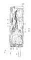
- FIG. 1is a front perspective view of a multi-drop closure system according to embodiments of the present invention with a first endplate configuration.
- FIG. 2is a cross-sectional view of the multi-drop closure system of FIG. 1 taken along the line 2 - 2 of FIG. 1 , with the first endplate configuration.
- FIG. 3is a cross-sectional view of the multi-drop closure system of FIG. 1 taken along the line 3 - 3 of FIG. 1 , with the first endplate configuration.
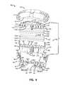
- FIG. 4is an exploded, fragmentary, perspective view of the multi-drop closure system of FIG. 1 , with the first endplate configuration.
- FIG. 5is a front perspective view of the multi-drop closure system of FIG. 1 with a second endplate configuration.
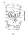
- FIG. 6is an exploded, fragmentary, perspective view of the multi-drop closure system of FIG. 1 , with the second endplate configuration.
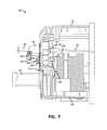
- FIG. 7is an enlarged, fragmentary, cross-sectional view of the multi-drop closure system of FIG. 1 taken along the line 7 - 7 of FIG. 5 , with the second endplate configuration.
- first, second, etc.may be used herein to describe various elements, components, regions, layers and/or sections, these elements, components, regions, layers and/or sections should not be limited by these terms. These terms are only used to distinguish one element, component, region, layer or section from another region, layer or section. Thus, a first element, component, region, layer or section discussed below could be termed a second element, component, region, layer or section without departing from the teachings of the present invention.
- spatially relative termssuch as “beneath”, “below”, “lower”, “above”, “upper” and the like, may be used herein for ease of description to describe one element or feature's relationship to another element(s) or feature(s) as illustrated in the figures. It will be understood that the spatially relative terms are intended to encompass different orientations of the device in use or operation in addition to the orientation depicted in the figures. For example, if the device in the figures is turned over, elements described as “below” or “beneath” other elements or features would then be oriented “above” the other elements or features. Thus, the exemplary term “below” can encompass both an orientation of above and below. The device may be otherwise oriented (rotated 90° or at other orientations) and the spatially relative descriptors used herein interpreted accordingly.
- Some embodiments of the present inventionprovide an enclosure system for use with fiber optic cabling.
- the enclosure systemmay make it easier to access and splice fibers running to living units or other customer locations at or near the end of fiber runs.
- the enclosure systemincludes an enclosure including some and/or all of the following features.
- the enclosure systemmay include an enclosure containing entry and/or egress points for fiber optic cables.
- One entry pointmay be used for an entering cable (feeder), one or more entry points may be used for branch and/or drop cable(s) exit, and a third may be used for exiting feeder (express) cable.
- the enclosure systemmay be a multi-drop or tap-off closure.
- a pass through fiber optic closureis provided.
- the closureis configured to receive a segment of a fiber optic cable, such that fibers thereof are expressed (uncut) through the closure without severing a buffer tube or buffer tubes of the cable segment (i.e., one or more of the buffer tubes are expressed through the closure).
- an outer protective buffer tube of the cable segmentextends fully and continuously through the closure.
- a telecommunications fiber optics splice enclosureis configurable for different fiber drop types by having changeable endplates to accommodate different methods for terminating a fiber drop cable.
- the enclosurecan be configured for different fiber drop types simply by changing the drop cable endplate to a different or alternative type or configuration. This can be accomplished in the factory or in the field.
- the enclosurecan thus be assembled to accommodate field splice or field terminated drop cables in one configuration, or assembled to accommodate factory terminated, hardened fiber optic drops in an alternative configuration.
- Embodiments of the inventionallow for a single enclosure type to be configurable for multiple drop cable types using the basic enclosure for either application. This limits the need for complete tooling for two separate enclosures. It also allows the enclosure to be configurable and reconfigured in the field.
- FIGS. 1-7A multi-drop enclosure system 10 for coupling an optical fiber branch cable 30 and/or optical fiber drop cables 40 to an optical fiber main cable 20 at a termination point to form a splice connection assembly is shown in FIGS. 1 and 5 .
- the system 10includes an enclosure 50 .
- the optical fiber main cable 20may be, for example, a feed from a service provider central office intended to provide service to individual subscriber locations in various locations in the field.
- the termination pointmay be positioned in the proximity of a neighborhood or the like and the branch cable 30 and the drop cables 40 may deliver an optical fiber connection to the subscriber location and/or to a junction box or the like where, for example, a copper connection may be routed for the last leg to the subscriber location.
- drop cables 40may be routed directly from the enclosure system 10 to the subscriber location (e.g., house).
- the portion of the cable 20 shown in the figurescorresponds to a termination point, where a splice may be made to the main cable 20 , and it will be understood that there are typically branch and drop cables spliced to the main cable 20 at a plurality of longitudinally displaced termination points selected to be positioned at desired locations in the field, such as in a neighborhood or the like.
- the illustrated optical fiber main cable 20includes a cable jacket 22 surrounding a plurality or bundle of buffer tubes 24 , and one or more optical fibers 26 extending through each buffer tube 24 .
- the cable 20may including further components such as a tubular metal grounding shield, or one or more strength members.
- the cable 20may include one or more fiber optic ribbons surrounded by a jacket. It will be appreciated that the description herein regarding routing, placement and organizing of the buffer tubes 24 likewise applies to fiber optic ribbons. However, in the case of a fiber optic ribbon cable, the buffer tube thereof typically will be severed to expose all of the ribbons rather than expressed through the enclosure 50 .
- the branch cable 30may include an outer jacket 32 , one or more buffer tubes 34 extending longitudinally through the outer jacket 32 , and one or more optical fibers 36 (typically, a plurality, e.g., seventy-two) extending through the buffer tube(s) 34 .
- the fibers 36may be grouped in respective buffer tubes 34 .
- the cable 30may include one or more fiber optic ribbons surrounded by a jacket and a buffer tube. It will be appreciated that the description herein regarding routing, placement and organizing of the buffer tubes 34 likewise applies to fiber optic ribbons.
- Each drop cable 40may likewise include an outer jacket 42 , a buffer tube 44 extending longitudinally through the outer jacket, and one or more optical fibers 46 extending through the buffer tube 44 .
- the fiber optic enclosure system 10includes an enclosure 50 , one or more splice trays 80 ( FIGS. 2 and 3 ), a tray tower 82 , grommets 54 , and interchangeable end wall or endplate assemblies 100 ( FIGS. 1 , 2 and 4 ) and 200 ( FIGS. 1-7 ).
- the system 10may further include a fiber optic pigtail 45 ( FIG. 7 ).
- the enclosure 50includes a base 60 and a lid or cover 70 .
- the base 60 and the cover 70collectively define an enclosure chamber 52 ( FIG. 2 ).
- the endplate assemblies 100 , 200also define a part of the chamber 52 .
- the base 60 and the cover 70are coupled together by a hinge 56 A on one lateral side and a latch or clasp 56 B on the opposing lateral side.
- the cover 70can be pivoted about the hinge 56 A between an open position allowing access for organizing or splicing optical fibers in the chamber 52 and a closed position extending over an access opening to the chamber 52 defined by the base 60 .
- the interface between the base 60 and the cover 70may be environmentally sealed so as to allow repeated access to the chamber 52 while maintaining an environmentally sealed space for splices when the cover 70 is in the closed position.
- the cover 70can be secured in the closed position by clamps, latches, straps or any other suitable mechanisms. Strain relief clamps may be secured to the base 60 to secure the cables 20 , 30 .
- the base 60includes an end wall 62 having a locator slot 62 A and cable slots 62 B defined therein.
- the base 60further defines an endplate slot 64 .
- the base 60has opposed side posts 66 each having a threaded fastener bore 66 A therein.
- the grommets 54are mounted in the cable slots 62 B. Each grommet 54 includes a port 54 A and a radially and longitudinally extending slit 54 B.
- the grommets 54may be formed of an elastomeric or other suitable sealing material.
- the cover 70includes an end wall 72 having an endplate mount slot 74 defined therein.
- the base 60 and the cover 70may be formed of any suitable rigid or semi-rigid material. According to some embodiments, the base 60 and the cover 70 are formed of a polymeric material. According to some embodiments, the base 60 and the cover 70 are formed of a polymeric material selected from the group consisting of polypropylene, polyethylene, nylon, ABS and PMMA. According to some embodiments, the base 60 and the cover 70 are each unitarily molded and, according to some embodiments, are each unitarily injection molded.
- the endplate assembly 100includes an upper gasket carrier 110 , a lower gasket carrier 120 , an upper gasket 140 , a lower gasket 142 , a top threaded fastener (e.g., self-tapping screw) 150 , and side threaded fasteners 152 .
- an upper gasket carrier 110e.g., a lower gasket carrier 120 , an upper gasket 140 , a lower gasket 142 , a top threaded fastener (e.g., self-tapping screw) 150 , and side threaded fasteners 152 .
- a top threaded fastenere.g., self-tapping screw
- the upper gasket carrier 110includes a base 112 and a series of partitions 114 extending from the base 112 .
- a series of slots 114 Aare defined between the partitions 114 .
- a fastener hole 116extends through the base 112 .
- a downwardly facing gasket slot 119is defined in the carrier 110 .
- the lower gasket carrier 120includes a base 122 having a locator feature 122 A.
- the lower gasket carrier 120further includes a series of partitions 124 defining a series of slots 124 A therebetween. Fastener holes 126 and side slots 128 are located at on either lateral side of the base 122 .
- An upwardly facing gasket slot 129is defined the carrier 120 .
- the gasket carriers 110 , 120may be formed of any suitable rigid or semi-rigid material.
- the gasket carriers 110 , 120may be formed of different material than the cover 70 and base 60 .
- the gasket carriers 110 , 120are formed of a polymeric material.
- the gasket carriers 110 , 120are formed of a polymeric material selected from the group consisting of polypropylene, polyethylene, nylon, ABS and PMMA.
- the gasket carriers 110 , 120are each unitarily molded and, according to some embodiments, are each unitarily injection molded.
- the upper gasket 140may include two gasket layers 140 A that are bonded together.
- the upper gasket 140is seated in the gasket carrier slot 119 such that an engagement surface 140 B faces downwardly.
- the gasket 140is secured in the slot 119 by adhesive, for example.
- the lower gasket 142may include two gasket layers 142 A that are bonded together.
- the lower gasket 142is seated in the gasket carrier slot 129 such that an engagement surface 142 B faces upwardly.
- the gasket 142is secured in the slot 129 by adhesive, for example.
- the gaskets 140 , 142may be formed of any suitable material such as, for example, compressible elastomeric foam.
- the endplate assembly 200includes a faceplate 210 having a bottom edge portion 212 , a top edge portion 214 , and a locator feature 216 depending from the bottom edge portion 212 .
- a plurality of connector ports 220extend through the faceplate 210 and are each surrounded by an annular O-ring pocket groove 222 .
- Side slots 224 and fastener holes 226are provided on opposed ends of the faceplate 210 .
- the faceplate 210may be formed of any suitable rigid or semi-rigid material. According to some embodiments, the faceplate 210 is formed of a polymeric material. According to some embodiments, the faceplate 210 is formed of a polymeric material selected from the group consisting of polypropylene, polyethylene, nylon, ABS and PMMA. According to some embodiments, the faceplate 210 is unitarily molded and, according to some embodiments, are each unitarily injection molded.
- a hardened fiber optic connector (HFOC) or fiber optic connector assembly 240( FIGS. 6 and 7 ) is mounted or seated in each port 220 .
- Each connector assembly 240includes a body 242 , a front end connector 244 , a back end connector 246 , a threaded portion 242 A, a cap 250 , an O-ring 252 , and a nut 254 mounted on each threaded portion 242 A.
- the O-rings 252are seated in the O-ring pocket grooves 222 to form an environmental seal about the connector assembly 240 .
- the fiber optic connector assemblies 240may include any suitable type of fiber optic connector. Suitable fiber optic connectors may include the DLX fiber optic connector available from ADC Telecommunications.
- the enclosure system 10may be assembled as follows in accordance with embodiments of the invention.
- the enclosure 50 , the tray tower 82 and the splice trays 80may be assembled in known or other suitable manner.
- the splice trays 80can be pivotally mounted on the tray tower 82 to cantilever therefrom.
- the appropriate one of the endplate assemblies 100 , 200is chosen depending on the intended usage or functionality of the fully assembled fiber optic enclosure. More particularly, if it is desired to enable an installer to route drop cables directly into the chamber 52 rather than terminating at a fiber optic connector on the exterior of the enclosure 50 , the endplate assembly 100 is installed. On the other hand, if it is desired to enable an installer to terminate a drop cable at a fiber optic connector on the exterior of the enclosure 50 , the endplate assembly 200 is installed. According to some embodiments, this selection and the endplate assembly installing steps described below are executed by the manufacturer (i.e., at the factory) and delivered to the end user or installer preconfigured.
- this selection and the endplate assembly installing steps described beloware executed by the installer in the field, for example.
- the installermay be provided with a kit or inventory including enclosures 50 , endplate assemblies 100 , and endplate assemblies 200 to be combined as needed.
- an endless length of the main cable 20is routed into and out of the enclosure 50 .
- the main cable 20may be coiled in the chamber 52 .
- a section of the jacket 22is removed to expose a bundle of buffer tubes (or ribbons) 24 containing optical fibers.
- the enclosure housing 50is opened or retained in the open position to provide access to the trays 80 .
- the cable 30 , 40is trimmed and inserted into the enclosure through a suitable port. The installer can select and sever a corresponding fiber 26 from a selected buffer tube 24 (or ribbon).
- the installercuts the buffer tube 24 to access the fiber.
- the cut fiber 26is routed to the branch fiber 36 or drop fiber 46 on the top side of a tray 80 and suitably spliced (e.g., fused or mechanically spliced) to the fiber 36 , 46 .
- the splice formed therebymay be mounted in the splice tray 80 .
- the installercan thereafter close the cover 70 .
- the manufacturer or installermay (e.g., at the time of the initial installation or subsequently) sever a buffer tube 24 or a fiber 26 and splice the fiber 26 as described above while leaving one or more of the other buffer tubes or fibers of the buffer tube (or ribbon) from which the fiber is separated uncut (i.e., the remaining fibers of the buffer tube or ribbon remain intact and are expressed).
- one or more pigtails 45are spliced to respective fibers 26 of the main cable 20 and are each plugged into the back of a respective connector assembly 240 . This would typically be done in the field at the time the enclosure 50 is installed. The spliced pigtails 45 plugged into the backs of the connector assemblies 240 would then be waiting available for drop cables 40 to be plugged in (e.g., on a customer-by-customer basis when service is required).
- the enclosure 50may be manufactured, pre-assembled and provided to the installer as a “stubbed” version with the splicing of the pigtails 45 to the main cable 20 being done in the factory, with the pigtails 45 being plugged into the backs of the connector assemblies 240 at the factory as well.
- the branch or drop cablemay include multiple fibers that may be spliced to multiple ones of the main cable fibers, individually or as a mass splice. Multiple branch or drop cables may be spliced to the main cable fibers.
- the upper gasket carrier 110is inserted into the slot 74 of the cover 70 and secured by a fastener 150 inserted through the hole 116 and into the cover 70 .
- the lower gasket carrier 142is inserted into the slot 64 such that the locator feature 122 A seats in the locator slot 62 A.
- the lower gasket carrier 120is removably secured on the base 60 by screws 152 inserted through the holes 126 and the screw bores 66 A.
- the gaskets 140 , 142may be mounted in the gasket carriers 110 , 120 before or after mounting the gasket carriers 110 , 120 on the enclosure 50 .
- an endless length of the main cable 20can be routed into and out of the chamber 52 through the ports 54 A. More particularly, the cover 70 is opened and the screws 152 are removed from the holes 126 and the screw bores 66 A to release the lower gasket carrier 120 . The lower gasket carrier 120 is lifted out to expose the slits 54 B in the grommets 54 . Sections of the cable 20 can then be pressed down laterally through the slits 54 B and the open top sides of the slots 62 B to install the cable 20 in the ports 54 A.
- the operatorwill pull the grommet 54 out of the selected cable slot 62 B, insert the cable 20 into the grommet 54 (laterally through the slit 54 B or axially through the port 54 A), and then re-install the grommet 54 with the cable 20 therein in the cable slot 62 B by pushing the grommet 54 laterally down into the cable slot 62 B.
- the lower gasket carrier 120is then re-inserted into the slot 64 such that the locator feature 122 A seats in the locator slot 62 A, and removably secured on the base 60 by the screws 152 inserted through the holes 126 and the screw bores 66 A.
- the branch cable 30can be routed into the chamber 52 through one of the ports 54 A in the same manner.
- the installed lower gasket carrierwill prevent lateral removal of the cables 20 , 30 from the ports 54 A through the slits 54 B. Ordinarily, it will not be necessary to access the slits 54 B again. However, the slits 54 B can be exposed again using the foregoing technique, if desired.
- One or more fibers 36 of the branch cable 30can be spliced to fibers 26 of the main cable 20 as discussed above.
- the usercan open the cover 70 and make the desired splices in the chamber 52 .
- the usercan route the drop cable 40 between the gaskets 140 , 142 and close the cover 70 onto the base 60 such that the gaskets 140 , 142 compress about the drop cable 40 and the cable 40 seats in a pass through port 160 defined by the opposed and mated slots 114 A, 124 A.
- One or more additional drop cables 40can be spliced and sealed in the same manner and each such cable 40 may be routed through a respective port 160 as shown in FIG. 1 .
- the centermost port 160is adapted to receive a flat drop cable 40 whereas the remaining ports 160 are configured to receive flat or round drop cables 40 of varying diameters.
- the bottom edge portion 212 of the endplate assembly 200is inserted into the slot 64 of the base 60 and the locator feature 216 is inserted in the slot 62 A.
- the side posts 66are received in the side slots 224 .
- the endplate assembly 200is removably secured on the base 60 by screws 228 inserted through the holes 226 and the screw bores 66 A.
- the cover 70is closed, the upper edge portion 214 is received in the slot 74 of the cover 70 .
- the screws 228can be removed from the holes 226 and the screw bores 66 A and the endplate assembly can be lifted out of the base 60 generally as described above for the lower gasket carrier 120 to access the slits 54 B of the grommets.
- the endplate assembly 200can be reinstalled on the base 60 .
- the usercan select a fiber optic connector assembly 240 , remove the cap 250 therefrom, and engage the drop cable connector 48 with the front end connector 244 as shown in FIG. 5 .
- the back end connector 246must also be connected to a fiber within the enclosure. This may be accomplished in any suitable manner such as, for example, by use of a pigtail 45 ( FIG. 7 ) having a fiber optic connector 49 and an optical fiber segment extending to a splice tray 80 .
- fiber optic enclosure systemse.g., the fiber optic enclosure system 10
- the fiber optic enclosure systemscan thereby reduce the costs associated with manufacturing enclosures or maintaining a supply of enclosures in inventory.
- endplate assembliesWhile particular configurations of endplate assemblies have been described and illustrated, other configurations may be employed.
- the endplate assemblymay have more or fewer fiber optic connectors, drop cable slots of different shapes, sizes and arrangements, and/or different types of cable sealing gaskets.
Landscapes
- Physics & Mathematics (AREA)
- General Physics & Mathematics (AREA)
- Optics & Photonics (AREA)
- Light Guides In General And Applications Therefor (AREA)
Abstract
Description
Claims (14)
Priority Applications (1)
| Application Number | Priority Date | Filing Date | Title |
|---|---|---|---|
| US13/404,970US8891928B2 (en) | 2011-03-07 | 2012-02-24 | Fiber optic splice enclosures having interchangeable endplate assemblies and methods including the same |
Applications Claiming Priority (2)
| Application Number | Priority Date | Filing Date | Title |
|---|---|---|---|
| US201161449941P | 2011-03-07 | 2011-03-07 | |
| US13/404,970US8891928B2 (en) | 2011-03-07 | 2012-02-24 | Fiber optic splice enclosures having interchangeable endplate assemblies and methods including the same |
Publications (2)
| Publication Number | Publication Date |
|---|---|
| US20120230644A1 US20120230644A1 (en) | 2012-09-13 |
| US8891928B2true US8891928B2 (en) | 2014-11-18 |
Family
ID=46000313
Family Applications (1)
| Application Number | Title | Priority Date | Filing Date |
|---|---|---|---|
| US13/404,970Active2032-11-29US8891928B2 (en) | 2011-03-07 | 2012-02-24 | Fiber optic splice enclosures having interchangeable endplate assemblies and methods including the same |
Country Status (3)
| Country | Link |
|---|---|
| US (1) | US8891928B2 (en) |
| EP (1) | EP2684088B1 (en) |
| WO (1) | WO2012158233A1 (en) |
Cited By (3)
| Publication number | Priority date | Publication date | Assignee | Title |
|---|---|---|---|---|
| US20190237901A1 (en)* | 2018-01-26 | 2019-08-01 | Harting Electric Gmbh & Co. Kg | Sealing insert |
| US11600981B2 (en)* | 2017-04-10 | 2023-03-07 | Igus Gmbh | Strain relief for quick assembly for a cable carrier |
| US20230280540A1 (en)* | 2022-03-03 | 2023-09-07 | Ppc Broadband, Inc. | Cable enclosure assembly having receiving area configured to alternatively receive cable retainer and cable adapter to allow plurality of configurations |
Families Citing this family (16)
| Publication number | Priority date | Publication date | Assignee | Title |
|---|---|---|---|---|
| CN101726802A (en)* | 2008-10-28 | 2010-06-09 | 上海瑞侃电缆附件有限公司 | Optical fiber terminal box |
| WO2012158233A1 (en)* | 2011-03-07 | 2012-11-22 | Tyco Electronics Corporation | Fiber optic splice enclosures having interchangeable endplate assemblies and methods including the same |
| CA2877896C (en) | 2011-06-24 | 2020-07-21 | Adc Telecommunications, Inc. | Fiber termination enclosure with modular plate assemblies |
| WO2013007662A2 (en)* | 2011-07-11 | 2013-01-17 | Tyco Electronics Raychem Bvba | Telecommunications enclosure with splice tray assembly |
| US8770861B2 (en)* | 2011-09-27 | 2014-07-08 | Tyco Electronics Corporation | Outside plant termination enclosure |
| WO2015028428A1 (en)* | 2013-08-24 | 2015-03-05 | Tyco Electronics Raychem Bvba | Sealing structures for optical cable closure |
| CN108713157B (en)* | 2016-03-09 | 2020-10-09 | 华为技术有限公司 | Fiber optic cable distribution box and fiber optic cable distribution device |
| US11251596B2 (en) | 2017-03-09 | 2022-02-15 | CommScope Connectivity Belgium BVBA | Gel seal and system incorporating gel seal |
| US11194111B2 (en) | 2017-06-15 | 2021-12-07 | Commscope Technologies Llc | Fiber optic splice closure and assemblies |
| WO2020061283A1 (en) | 2018-09-21 | 2020-03-26 | Commscope Technologies Llc | Fiber optic cable sealing device |
| RU2717137C1 (en)* | 2019-03-20 | 2020-03-18 | Закрытое Акционерное Общество "Связьстройдеталь" | Optical cable installation and distribution device housing |
| BR102019023385A2 (en)* | 2019-11-07 | 2021-05-18 | Furukawa Electric Latam S.A. | termination box and optical branch |
| EP4551981A1 (en)* | 2022-07-08 | 2025-05-14 | AFL Telecommunications LLC | Telecommunication enclosures |
| USD1083866S1 (en)* | 2022-08-11 | 2025-07-15 | Yaoz Solutions Ltd. | Fiber optic splice closure |
| IT202300005586A1 (en)* | 2023-03-23 | 2024-09-23 | Prysmian Spa | AN OPTICAL JUNCTION BOX |
| EP4521151A1 (en)* | 2023-09-08 | 2025-03-12 | Corning Research & Development Corporation | Sealing mechanism on fiber optic terminals |
Citations (18)
| Publication number | Priority date | Publication date | Assignee | Title |
|---|---|---|---|---|
| EP0320236A2 (en)* | 1987-12-11 | 1989-06-14 | Minnesota Mining And Manufacturing Company | Cable closure end cap |
| FR2660118A1 (en) | 1990-03-20 | 1991-09-27 | Francelco Sa | Method of making a sealed connection module and connector including such a module |
| US5093885A (en)* | 1990-07-11 | 1992-03-03 | Adc Telecommunications, Inc. | Fiber optic connector module |
| US5313546A (en)* | 1991-11-29 | 1994-05-17 | Sirti, S.P.A. | Hermetically sealed joint cover for fibre optic cables |
| US5737475A (en)* | 1997-01-17 | 1998-04-07 | Leviton Manufacturing Co., Inc. | Universal multimedia connection unit |
| US5886300A (en) | 1996-04-30 | 1999-03-23 | The Whitaker Corporation | Plug for a sealing grommet |
| US6118076A (en)* | 1995-06-30 | 2000-09-12 | N.V. Raychem S.A. | Cable seal insert |
| US6315598B1 (en)* | 2000-02-01 | 2001-11-13 | Adc Telecommunications, Inc. | Outlet box with cable management spool |
| US20020064363A1 (en) | 2000-10-17 | 2002-05-30 | Preformed Line Products Company | Cable closure and assembly |
| US6533472B1 (en) | 1999-10-19 | 2003-03-18 | Alcoa Fujikura Limited | Optical fiber splice closure assembly |
| US20060083475A1 (en) | 2003-10-06 | 2006-04-20 | Christopher Grubish | Optical fiber splice case |
| US20070183732A1 (en)* | 2006-02-08 | 2007-08-09 | Charles Industries, Ltd. | Fiber optic splice enclosure |
| US20080205843A1 (en)* | 2007-02-28 | 2008-08-28 | Guy Castonguay | Fiber optic drop terminals for multiple dwelling units |
| US20090152004A1 (en) | 2006-06-23 | 2009-06-18 | Pierre Bonvallat | Cable closure end cap |
| US20110129186A1 (en)* | 2009-11-30 | 2011-06-02 | Lewallen C Paul | Fiber Optic Module Assembly and Associated Methods |
| US20120257862A1 (en)* | 2011-04-06 | 2012-10-11 | Preformed Line Products Company | Adaptable connection enclosure |
| WO2012158233A1 (en)* | 2011-03-07 | 2012-11-22 | Tyco Electronics Corporation | Fiber optic splice enclosures having interchangeable endplate assemblies and methods including the same |
| US20120308189A1 (en)* | 2009-10-14 | 2012-12-06 | Afl Telecommunications Llc | Fiber splice enclosure |
- 2012
- 2012-02-24WOPCT/US2012/026513patent/WO2012158233A1/enactiveApplication Filing
- 2012-02-24EPEP12716762.5Apatent/EP2684088B1/ennot_activeNot-in-force
- 2012-02-24USUS13/404,970patent/US8891928B2/enactiveActive
Patent Citations (18)
| Publication number | Priority date | Publication date | Assignee | Title |
|---|---|---|---|---|
| EP0320236A2 (en)* | 1987-12-11 | 1989-06-14 | Minnesota Mining And Manufacturing Company | Cable closure end cap |
| FR2660118A1 (en) | 1990-03-20 | 1991-09-27 | Francelco Sa | Method of making a sealed connection module and connector including such a module |
| US5093885A (en)* | 1990-07-11 | 1992-03-03 | Adc Telecommunications, Inc. | Fiber optic connector module |
| US5313546A (en)* | 1991-11-29 | 1994-05-17 | Sirti, S.P.A. | Hermetically sealed joint cover for fibre optic cables |
| US6118076A (en)* | 1995-06-30 | 2000-09-12 | N.V. Raychem S.A. | Cable seal insert |
| US5886300A (en) | 1996-04-30 | 1999-03-23 | The Whitaker Corporation | Plug for a sealing grommet |
| US5737475A (en)* | 1997-01-17 | 1998-04-07 | Leviton Manufacturing Co., Inc. | Universal multimedia connection unit |
| US6533472B1 (en) | 1999-10-19 | 2003-03-18 | Alcoa Fujikura Limited | Optical fiber splice closure assembly |
| US6315598B1 (en)* | 2000-02-01 | 2001-11-13 | Adc Telecommunications, Inc. | Outlet box with cable management spool |
| US20020064363A1 (en) | 2000-10-17 | 2002-05-30 | Preformed Line Products Company | Cable closure and assembly |
| US20060083475A1 (en) | 2003-10-06 | 2006-04-20 | Christopher Grubish | Optical fiber splice case |
| US20070183732A1 (en)* | 2006-02-08 | 2007-08-09 | Charles Industries, Ltd. | Fiber optic splice enclosure |
| US20090152004A1 (en) | 2006-06-23 | 2009-06-18 | Pierre Bonvallat | Cable closure end cap |
| US20080205843A1 (en)* | 2007-02-28 | 2008-08-28 | Guy Castonguay | Fiber optic drop terminals for multiple dwelling units |
| US20120308189A1 (en)* | 2009-10-14 | 2012-12-06 | Afl Telecommunications Llc | Fiber splice enclosure |
| US20110129186A1 (en)* | 2009-11-30 | 2011-06-02 | Lewallen C Paul | Fiber Optic Module Assembly and Associated Methods |
| WO2012158233A1 (en)* | 2011-03-07 | 2012-11-22 | Tyco Electronics Corporation | Fiber optic splice enclosures having interchangeable endplate assemblies and methods including the same |
| US20120257862A1 (en)* | 2011-04-06 | 2012-10-11 | Preformed Line Products Company | Adaptable connection enclosure |
Non-Patent Citations (5)
| Title |
|---|
| "FOSC 450 Gel-Sealed Fiber Optic Splice Closure Ordering Guide" Tyco Electronics Corporation, ©2004-2009 1654571 F429.11/09 (32 pages). |
| "FOSC 600 C and D Fiber Optic Splice Closure Installation Instruction" Tyco Electronics Corporation, ©2003, 2008 PML MP0310 F392.04/08 (15 pages). |
| "FOSC 600 Fiber Optic Splice Closure" Tyco Electronics Corporation, ©2005, 2008 F382.06/08 (2 pages). |
| International Preliminary Report on Patentability corresponding to International application No. PCT/US2012/026513; Date of Mailing: Sep. 19, 2013, 8 pages. |
| Notification of Transmittal of the International Search Report and the Written Opinion of the International Searching Authority, or the Declaration in corresponding PCT Application No. PCT/US2012/026513 mailed Jun. 18, 2012 (13 pages). |
Cited By (4)
| Publication number | Priority date | Publication date | Assignee | Title |
|---|---|---|---|---|
| US11600981B2 (en)* | 2017-04-10 | 2023-03-07 | Igus Gmbh | Strain relief for quick assembly for a cable carrier |
| US20190237901A1 (en)* | 2018-01-26 | 2019-08-01 | Harting Electric Gmbh & Co. Kg | Sealing insert |
| US10461463B2 (en)* | 2018-01-26 | 2019-10-29 | Harting Electric Gmbh & Co. Kg | Sealing insert |
| US20230280540A1 (en)* | 2022-03-03 | 2023-09-07 | Ppc Broadband, Inc. | Cable enclosure assembly having receiving area configured to alternatively receive cable retainer and cable adapter to allow plurality of configurations |
Also Published As
| Publication number | Publication date |
|---|---|
| WO2012158233A1 (en) | 2012-11-22 |
| US20120230644A1 (en) | 2012-09-13 |
| EP2684088B1 (en) | 2018-01-03 |
| EP2684088A1 (en) | 2014-01-15 |
Similar Documents
| Publication | Publication Date | Title |
|---|---|---|
| US8891928B2 (en) | Fiber optic splice enclosures having interchangeable endplate assemblies and methods including the same | |
| US11592636B2 (en) | Wall box adapted to be mounted at a mid-span access location of a telecommunications cable | |
| US7444056B2 (en) | Optical network architecture and terminals for use in such networks | |
| EP3132298B1 (en) | Fiber optic enclosure with cable management drawer | |
| US8879883B2 (en) | Optical fiber cable inlet device and telecommunications enclosure system | |
| US8929708B2 (en) | Fiber organizer and distribution box | |
| US10031305B2 (en) | Distribution device with incrementally added splitters | |
| US7751675B2 (en) | Wall box adapted to be mounted at a mid-span access location of a telecommunications cable | |
| US20200088964A1 (en) | Mechanical cable entry port | |
| US20060153516A1 (en) | Network interface device having integral slack storage compartment | |
| US20060153362A1 (en) | Network interface device for fiber optic communications network | |
| US7668432B2 (en) | Multi-drop closure systems and methods for fiber optic cabling | |
| US20100111484A1 (en) | Fiber optic connector storage apparatus and methods for using the same | |
| US20110129186A1 (en) | Fiber Optic Module Assembly and Associated Methods | |
| US7359613B2 (en) | Optical fiber termination apparatus for taut sheath splicing and method for using the same | |
| US9140870B2 (en) | Retainer tab assemblies and slack basket systems, fiber optic enclosures and methods including the same | |
| US20180284379A1 (en) | Segregated fiber in a splice cassette | |
| CN114765355A (en) | Tapping cable box | |
| EP3066507A1 (en) | Fiber termination point with overlength storage |
Legal Events
| Date | Code | Title | Description |
|---|---|---|---|
| AS | Assignment | Owner name:TYCO ELECTRONICS CORPORATION, PENNSYLVANIA Free format text:ASSIGNMENT OF ASSIGNORS INTEREST;ASSIGNORS:MARMON, THOMAS ROSS;THOMPSON, ROY KELLER;SIGNING DATES FROM 20120223 TO 20120224;REEL/FRAME:027761/0466 | |
| STCF | Information on status: patent grant | Free format text:PATENTED CASE | |
| AS | Assignment | Owner name:TYCO ELECTRONICS SERVICES GMBH, SWITZERLAND Free format text:ASSIGNMENT OF ASSIGNORS INTEREST;ASSIGNOR:TYCO ELECTRONICS CORPORATION;REEL/FRAME:036074/0740 Effective date:20150410 | |
| AS | Assignment | Owner name:COMMSCOPE EMEA LIMITED, IRELAND Free format text:ASSIGNMENT OF ASSIGNORS INTEREST;ASSIGNOR:TYCO ELECTRONICS SERVICES GMBH;REEL/FRAME:036956/0001 Effective date:20150828 | |
| AS | Assignment | Owner name:COMMSCOPE TECHNOLOGIES LLC, NORTH CAROLINA Free format text:ASSIGNMENT OF ASSIGNORS INTEREST;ASSIGNOR:COMMSCOPE EMEA LIMITED;REEL/FRAME:037012/0001 Effective date:20150828 | |
| AS | Assignment | Owner name:JPMORGAN CHASE BANK, N.A., AS COLLATERAL AGENT, ILLINOIS Free format text:PATENT SECURITY AGREEMENT (TERM);ASSIGNOR:COMMSCOPE TECHNOLOGIES LLC;REEL/FRAME:037513/0709 Effective date:20151220 Owner name:JPMORGAN CHASE BANK, N.A., AS COLLATERAL AGENT, ILLINOIS Free format text:PATENT SECURITY AGREEMENT (ABL);ASSIGNOR:COMMSCOPE TECHNOLOGIES LLC;REEL/FRAME:037514/0196 Effective date:20151220 Owner name:JPMORGAN CHASE BANK, N.A., AS COLLATERAL AGENT, IL Free format text:PATENT SECURITY AGREEMENT (ABL);ASSIGNOR:COMMSCOPE TECHNOLOGIES LLC;REEL/FRAME:037514/0196 Effective date:20151220 Owner name:JPMORGAN CHASE BANK, N.A., AS COLLATERAL AGENT, IL Free format text:PATENT SECURITY AGREEMENT (TERM);ASSIGNOR:COMMSCOPE TECHNOLOGIES LLC;REEL/FRAME:037513/0709 Effective date:20151220 | |
| MAFP | Maintenance fee payment | Free format text:PAYMENT OF MAINTENANCE FEE, 4TH YEAR, LARGE ENTITY (ORIGINAL EVENT CODE: M1551) Year of fee payment:4 | |
| AS | Assignment | Owner name:ANDREW LLC, NORTH CAROLINA Free format text:RELEASE BY SECURED PARTY;ASSIGNOR:JPMORGAN CHASE BANK, N.A.;REEL/FRAME:048840/0001 Effective date:20190404 Owner name:ALLEN TELECOM LLC, ILLINOIS Free format text:RELEASE BY SECURED PARTY;ASSIGNOR:JPMORGAN CHASE BANK, N.A.;REEL/FRAME:048840/0001 Effective date:20190404 Owner name:COMMSCOPE TECHNOLOGIES LLC, NORTH CAROLINA Free format text:RELEASE BY SECURED PARTY;ASSIGNOR:JPMORGAN CHASE BANK, N.A.;REEL/FRAME:048840/0001 Effective date:20190404 Owner name:COMMSCOPE, INC. OF NORTH CAROLINA, NORTH CAROLINA Free format text:RELEASE BY SECURED PARTY;ASSIGNOR:JPMORGAN CHASE BANK, N.A.;REEL/FRAME:048840/0001 Effective date:20190404 Owner name:REDWOOD SYSTEMS, INC., NORTH CAROLINA Free format text:RELEASE BY SECURED PARTY;ASSIGNOR:JPMORGAN CHASE BANK, N.A.;REEL/FRAME:048840/0001 Effective date:20190404 Owner name:COMMSCOPE TECHNOLOGIES LLC, NORTH CAROLINA Free format text:RELEASE BY SECURED PARTY;ASSIGNOR:JPMORGAN CHASE BANK, N.A.;REEL/FRAME:049260/0001 Effective date:20190404 Owner name:ANDREW LLC, NORTH CAROLINA Free format text:RELEASE BY SECURED PARTY;ASSIGNOR:JPMORGAN CHASE BANK, N.A.;REEL/FRAME:049260/0001 Effective date:20190404 Owner name:ALLEN TELECOM LLC, ILLINOIS Free format text:RELEASE BY SECURED PARTY;ASSIGNOR:JPMORGAN CHASE BANK, N.A.;REEL/FRAME:049260/0001 Effective date:20190404 Owner name:REDWOOD SYSTEMS, INC., NORTH CAROLINA Free format text:RELEASE BY SECURED PARTY;ASSIGNOR:JPMORGAN CHASE BANK, N.A.;REEL/FRAME:049260/0001 Effective date:20190404 Owner name:COMMSCOPE, INC. OF NORTH CAROLINA, NORTH CAROLINA Free format text:RELEASE BY SECURED PARTY;ASSIGNOR:JPMORGAN CHASE BANK, N.A.;REEL/FRAME:049260/0001 Effective date:20190404 | |
| AS | Assignment | Owner name:JPMORGAN CHASE BANK, N.A., NEW YORK Free format text:ABL SECURITY AGREEMENT;ASSIGNORS:COMMSCOPE, INC. OF NORTH CAROLINA;COMMSCOPE TECHNOLOGIES LLC;ARRIS ENTERPRISES LLC;AND OTHERS;REEL/FRAME:049892/0396 Effective date:20190404 Owner name:WILMINGTON TRUST, NATIONAL ASSOCIATION, AS COLLATE Free format text:PATENT SECURITY AGREEMENT;ASSIGNOR:COMMSCOPE TECHNOLOGIES LLC;REEL/FRAME:049892/0051 Effective date:20190404 Owner name:JPMORGAN CHASE BANK, N.A., NEW YORK Free format text:TERM LOAN SECURITY AGREEMENT;ASSIGNORS:COMMSCOPE, INC. OF NORTH CAROLINA;COMMSCOPE TECHNOLOGIES LLC;ARRIS ENTERPRISES LLC;AND OTHERS;REEL/FRAME:049905/0504 Effective date:20190404 Owner name:WILMINGTON TRUST, NATIONAL ASSOCIATION, AS COLLATERAL AGENT, CONNECTICUT Free format text:PATENT SECURITY AGREEMENT;ASSIGNOR:COMMSCOPE TECHNOLOGIES LLC;REEL/FRAME:049892/0051 Effective date:20190404 | |
| AS | Assignment | Owner name:WILMINGTON TRUST, DELAWARE Free format text:SECURITY INTEREST;ASSIGNORS:ARRIS SOLUTIONS, INC.;ARRIS ENTERPRISES LLC;COMMSCOPE TECHNOLOGIES LLC;AND OTHERS;REEL/FRAME:060752/0001 Effective date:20211115 | |
| MAFP | Maintenance fee payment | Free format text:PAYMENT OF MAINTENANCE FEE, 8TH YEAR, LARGE ENTITY (ORIGINAL EVENT CODE: M1552); ENTITY STATUS OF PATENT OWNER: LARGE ENTITY Year of fee payment:8 | |
| AS | Assignment | Owner name:APOLLO ADMINISTRATIVE AGENCY LLC, NEW YORK Free format text:SECURITY INTEREST;ASSIGNORS:ARRIS ENTERPRISES LLC;COMMSCOPE TECHNOLOGIES LLC;COMMSCOPE INC., OF NORTH CAROLINA;AND OTHERS;REEL/FRAME:069889/0114 Effective date:20241217 | |
| AS | Assignment | Owner name:RUCKUS WIRELESS, LLC (F/K/A RUCKUS WIRELESS, INC.), NORTH CAROLINA Free format text:RELEASE OF SECURITY INTEREST AT REEL/FRAME 049905/0504;ASSIGNOR:JPMORGAN CHASE BANK, N.A., AS COLLATERAL AGENT;REEL/FRAME:071477/0255 Effective date:20241217 Owner name:COMMSCOPE TECHNOLOGIES LLC, NORTH CAROLINA Free format text:RELEASE OF SECURITY INTEREST AT REEL/FRAME 049905/0504;ASSIGNOR:JPMORGAN CHASE BANK, N.A., AS COLLATERAL AGENT;REEL/FRAME:071477/0255 Effective date:20241217 Owner name:COMMSCOPE, INC. OF NORTH CAROLINA, NORTH CAROLINA Free format text:RELEASE OF SECURITY INTEREST AT REEL/FRAME 049905/0504;ASSIGNOR:JPMORGAN CHASE BANK, N.A., AS COLLATERAL AGENT;REEL/FRAME:071477/0255 Effective date:20241217 Owner name:ARRIS SOLUTIONS, INC., NORTH CAROLINA Free format text:RELEASE OF SECURITY INTEREST AT REEL/FRAME 049905/0504;ASSIGNOR:JPMORGAN CHASE BANK, N.A., AS COLLATERAL AGENT;REEL/FRAME:071477/0255 Effective date:20241217 Owner name:ARRIS TECHNOLOGY, INC., NORTH CAROLINA Free format text:RELEASE OF SECURITY INTEREST AT REEL/FRAME 049905/0504;ASSIGNOR:JPMORGAN CHASE BANK, N.A., AS COLLATERAL AGENT;REEL/FRAME:071477/0255 Effective date:20241217 Owner name:ARRIS ENTERPRISES LLC (F/K/A ARRIS ENTERPRISES, INC.), NORTH CAROLINA Free format text:RELEASE OF SECURITY INTEREST AT REEL/FRAME 049905/0504;ASSIGNOR:JPMORGAN CHASE BANK, N.A., AS COLLATERAL AGENT;REEL/FRAME:071477/0255 Effective date:20241217 |