US8891924B2 - Magnetic-anchored robotic system - Google Patents
Magnetic-anchored robotic systemDownload PDFInfo
- Publication number
- US8891924B2 US8891924B2US13/835,680US201313835680AUS8891924B2US 8891924 B2US8891924 B2US 8891924B2US 201313835680 AUS201313835680 AUS 201313835680AUS 8891924 B2US8891924 B2US 8891924B2
- Authority
- US
- United States
- Prior art keywords
- entrance port
- surgical
- exemplary
- camera
- manipulator
- Prior art date
- Legal status (The legal status is an assumption and is not a legal conclusion. Google has not performed a legal analysis and makes no representation as to the accuracy of the status listed.)
- Active
Links
- 210000003815abdominal wallAnatomy0.000claimsdescription26
- 238000001727in vivoMethods0.000claimsdescription9
- 230000000295complement effectEffects0.000claimsdescription3
- 230000033001locomotionEffects0.000abstractdescription39
- 239000012636effectorSubstances0.000abstractdescription13
- 229910001111Fine metalInorganic materials0.000description10
- 238000003780insertionMethods0.000description9
- 230000037431insertionEffects0.000description9
- 238000004873anchoringMethods0.000description7
- 239000000463materialSubstances0.000description7
- 230000007246mechanismEffects0.000description7
- 239000002184metalSubstances0.000description7
- 229910052751metalInorganic materials0.000description7
- 230000003187abdominal effectEffects0.000description6
- 238000002324minimally invasive surgeryMethods0.000description6
- 230000008901benefitEffects0.000description5
- 238000001816coolingMethods0.000description5
- 230000000694effectsEffects0.000description5
- 238000010438heat treatmentMethods0.000description5
- 230000001960triggered effectEffects0.000description5
- 210000000683abdominal cavityAnatomy0.000description4
- 238000005516engineering processMethods0.000description4
- 238000001356surgical procedureMethods0.000description4
- 230000009471actionEffects0.000description3
- 230000003213activating effectEffects0.000description3
- 208000014674injuryDiseases0.000description3
- 238000000034methodMethods0.000description3
- 230000008733traumaEffects0.000description3
- XEEYBQQBJWHFJM-UHFFFAOYSA-NIronChemical compound[Fe]XEEYBQQBJWHFJM-UHFFFAOYSA-N0.000description2
- 210000001015abdomenAnatomy0.000description2
- 238000013459approachMethods0.000description2
- 238000004891communicationMethods0.000description2
- 239000012141concentrateSubstances0.000description2
- 230000008878couplingEffects0.000description2
- 238000010168coupling processMethods0.000description2
- 238000005859coupling reactionMethods0.000description2
- 238000011161developmentMethods0.000description2
- 230000018109developmental processEffects0.000description2
- 239000000835fiberSubstances0.000description2
- 230000004907fluxEffects0.000description2
- 238000005286illuminationMethods0.000description2
- 238000003384imaging methodMethods0.000description2
- 230000001976improved effectEffects0.000description2
- 230000005855radiationEffects0.000description2
- 238000000926separation methodMethods0.000description2
- 238000013519translationMethods0.000description2
- 210000000707wristAnatomy0.000description2
- 208000032544CicatrixDiseases0.000description1
- 206010019909HerniaDiseases0.000description1
- 208000002193PainDiseases0.000description1
- 206010048038Wound infectionDiseases0.000description1
- 238000012084abdominal surgeryMethods0.000description1
- 229920000249biocompatible polymerPolymers0.000description1
- 230000015572biosynthetic processEffects0.000description1
- 238000012512characterization methodMethods0.000description1
- 239000002131composite materialSubstances0.000description1
- 239000004020conductorSubstances0.000description1
- 238000011846endoscopic investigationMethods0.000description1
- 238000002674endoscopic surgeryMethods0.000description1
- 210000004247handAnatomy0.000description1
- 230000006698inductionEffects0.000description1
- 230000001939inductive effectEffects0.000description1
- 229910052742ironInorganic materials0.000description1
- XWHPIFXRKKHEKR-UHFFFAOYSA-Niron siliconChemical compound[Si].[Fe]XWHPIFXRKKHEKR-UHFFFAOYSA-N0.000description1
- 238000005339levitationMethods0.000description1
- 229910001092metal group alloyInorganic materials0.000description1
- 230000003287optical effectEffects0.000description1
- 210000000056organAnatomy0.000description1
- 239000004033plasticSubstances0.000description1
- 229920003023plasticPolymers0.000description1
- 230000008569processEffects0.000description1
- 238000002278reconstructive surgeryMethods0.000description1
- 238000002432robotic surgeryMethods0.000description1
- 231100000241scarToxicity0.000description1
- 230000037390scarringEffects0.000description1
- 230000037387scarsEffects0.000description1
- 229910001285shape-memory alloyInorganic materials0.000description1
- 230000008054signal transmissionEffects0.000description1
- 239000013589supplementSubstances0.000description1
- 210000001113umbilicusAnatomy0.000description1
Images


Classifications
- A61B19/20—
- B—PERFORMING OPERATIONS; TRANSPORTING
- B25—HAND TOOLS; PORTABLE POWER-DRIVEN TOOLS; MANIPULATORS
- B25J—MANIPULATORS; CHAMBERS PROVIDED WITH MANIPULATION DEVICES
- B25J13/00—Controls for manipulators
- B25J13/08—Controls for manipulators by means of sensing devices, e.g. viewing or touching devices
- B25J13/088—Controls for manipulators by means of sensing devices, e.g. viewing or touching devices with position, velocity or acceleration sensors
- A—HUMAN NECESSITIES
- A61—MEDICAL OR VETERINARY SCIENCE; HYGIENE
- A61B—DIAGNOSIS; SURGERY; IDENTIFICATION
- A61B17/00—Surgical instruments, devices or methods
- A—HUMAN NECESSITIES
- A61—MEDICAL OR VETERINARY SCIENCE; HYGIENE
- A61B—DIAGNOSIS; SURGERY; IDENTIFICATION
- A61B17/00—Surgical instruments, devices or methods
- A61B17/00234—Surgical instruments, devices or methods for minimally invasive surgery
- A—HUMAN NECESSITIES
- A61—MEDICAL OR VETERINARY SCIENCE; HYGIENE
- A61B—DIAGNOSIS; SURGERY; IDENTIFICATION
- A61B17/00—Surgical instruments, devices or methods
- A61B17/34—Trocars; Puncturing needles
- A61B17/3417—Details of tips or shafts, e.g. grooves, expandable, bendable; Multiple coaxial sliding cannulas, e.g. for dilating
- A61B19/2203—
- A—HUMAN NECESSITIES
- A61—MEDICAL OR VETERINARY SCIENCE; HYGIENE
- A61B—DIAGNOSIS; SURGERY; IDENTIFICATION
- A61B34/00—Computer-aided surgery; Manipulators or robots specially adapted for use in surgery
- A61B34/30—Surgical robots
- A—HUMAN NECESSITIES
- A61—MEDICAL OR VETERINARY SCIENCE; HYGIENE
- A61B—DIAGNOSIS; SURGERY; IDENTIFICATION
- A61B34/00—Computer-aided surgery; Manipulators or robots specially adapted for use in surgery
- A61B34/70—Manipulators specially adapted for use in surgery
- A61B34/73—Manipulators for magnetic surgery
- A—HUMAN NECESSITIES
- A61—MEDICAL OR VETERINARY SCIENCE; HYGIENE
- A61B—DIAGNOSIS; SURGERY; IDENTIFICATION
- A61B34/00—Computer-aided surgery; Manipulators or robots specially adapted for use in surgery
- A61B34/70—Manipulators specially adapted for use in surgery
- A61B34/76—Manipulators having means for providing feel, e.g. force or tactile feedback
- A—HUMAN NECESSITIES
- A61—MEDICAL OR VETERINARY SCIENCE; HYGIENE
- A61B—DIAGNOSIS; SURGERY; IDENTIFICATION
- A61B90/00—Instruments, implements or accessories specially adapted for surgery or diagnosis and not covered by any of the groups A61B1/00 - A61B50/00, e.g. for luxation treatment or for protecting wound edges
- A61B90/10—Instruments, implements or accessories specially adapted for surgery or diagnosis and not covered by any of the groups A61B1/00 - A61B50/00, e.g. for luxation treatment or for protecting wound edges for stereotaxic surgery, e.g. frame-based stereotaxis
- A—HUMAN NECESSITIES
- A61—MEDICAL OR VETERINARY SCIENCE; HYGIENE
- A61B—DIAGNOSIS; SURGERY; IDENTIFICATION
- A61B17/00—Surgical instruments, devices or methods
- A61B17/34—Trocars; Puncturing needles
- A61B17/3417—Details of tips or shafts, e.g. grooves, expandable, bendable; Multiple coaxial sliding cannulas, e.g. for dilating
- A61B17/3421—Cannulas
- A61B17/3423—Access ports, e.g. toroid shape introducers for instruments or hands
- A—HUMAN NECESSITIES
- A61—MEDICAL OR VETERINARY SCIENCE; HYGIENE
- A61B—DIAGNOSIS; SURGERY; IDENTIFICATION
- A61B17/00—Surgical instruments, devices or methods
- A61B17/00234—Surgical instruments, devices or methods for minimally invasive surgery
- A61B2017/00238—Type of minimally invasive operation
- A61B2017/00283—Type of minimally invasive operation with a device releasably connected to an inner wall of the abdomen during surgery, e.g. an illumination source
- A—HUMAN NECESSITIES
- A61—MEDICAL OR VETERINARY SCIENCE; HYGIENE
- A61B—DIAGNOSIS; SURGERY; IDENTIFICATION
- A61B17/00—Surgical instruments, devices or methods
- A61B2017/00831—Material properties
- A61B2017/00876—Material properties magnetic
- A—HUMAN NECESSITIES
- A61—MEDICAL OR VETERINARY SCIENCE; HYGIENE
- A61B—DIAGNOSIS; SURGERY; IDENTIFICATION
- A61B17/00—Surgical instruments, devices or methods
- A61B17/34—Trocars; Puncturing needles
- A61B2017/348—Means for supporting the trocar against the body or retaining the trocar inside the body
- A61B2017/3482—Means for supporting the trocar against the body or retaining the trocar inside the body inside
- A61B2017/3484—Anchoring means, e.g. spreading-out umbrella-like structure
- A—HUMAN NECESSITIES
- A61—MEDICAL OR VETERINARY SCIENCE; HYGIENE
- A61B—DIAGNOSIS; SURGERY; IDENTIFICATION
- A61B34/00—Computer-aided surgery; Manipulators or robots specially adapted for use in surgery
- A61B34/30—Surgical robots
- A61B2034/302—Surgical robots specifically adapted for manipulations within body cavities, e.g. within abdominal or thoracic cavities
- A—HUMAN NECESSITIES
- A61—MEDICAL OR VETERINARY SCIENCE; HYGIENE
- A61B—DIAGNOSIS; SURGERY; IDENTIFICATION
- A61B90/00—Instruments, implements or accessories specially adapted for surgery or diagnosis and not covered by any of the groups A61B1/00 - A61B50/00, e.g. for luxation treatment or for protecting wound edges
- A61B90/36—Image-producing devices or illumination devices not otherwise provided for
- A61B90/37—Surgical systems with images on a monitor during operation
- A61B2090/371—Surgical systems with images on a monitor during operation with simultaneous use of two cameras
- Y—GENERAL TAGGING OF NEW TECHNOLOGICAL DEVELOPMENTS; GENERAL TAGGING OF CROSS-SECTIONAL TECHNOLOGIES SPANNING OVER SEVERAL SECTIONS OF THE IPC; TECHNICAL SUBJECTS COVERED BY FORMER USPC CROSS-REFERENCE ART COLLECTIONS [XRACs] AND DIGESTS
- Y10—TECHNICAL SUBJECTS COVERED BY FORMER USPC
- Y10S—TECHNICAL SUBJECTS COVERED BY FORMER USPC CROSS-REFERENCE ART COLLECTIONS [XRACs] AND DIGESTS
- Y10S901/00—Robots
- Y10S901/02—Arm motion controller
- Y10S901/09—Closed loop, sensor feedback controls arm movement
- Y—GENERAL TAGGING OF NEW TECHNOLOGICAL DEVELOPMENTS; GENERAL TAGGING OF CROSS-SECTIONAL TECHNOLOGIES SPANNING OVER SEVERAL SECTIONS OF THE IPC; TECHNICAL SUBJECTS COVERED BY FORMER USPC CROSS-REFERENCE ART COLLECTIONS [XRACs] AND DIGESTS
- Y10—TECHNICAL SUBJECTS COVERED BY FORMER USPC
- Y10S—TECHNICAL SUBJECTS COVERED BY FORMER USPC CROSS-REFERENCE ART COLLECTIONS [XRACs] AND DIGESTS
- Y10S901/00—Robots
- Y10S901/30—End effector
- Y10S901/31—Gripping jaw
- Y10S901/32—Servo-actuated
- Y10S901/34—Servo-actuated force feedback
- Y—GENERAL TAGGING OF NEW TECHNOLOGICAL DEVELOPMENTS; GENERAL TAGGING OF CROSS-SECTIONAL TECHNOLOGIES SPANNING OVER SEVERAL SECTIONS OF THE IPC; TECHNICAL SUBJECTS COVERED BY FORMER USPC CROSS-REFERENCE ART COLLECTIONS [XRACs] AND DIGESTS
- Y10—TECHNICAL SUBJECTS COVERED BY FORMER USPC
- Y10S—TECHNICAL SUBJECTS COVERED BY FORMER USPC CROSS-REFERENCE ART COLLECTIONS [XRACs] AND DIGESTS
- Y10S901/00—Robots
- Y10S901/30—End effector
- Y10S901/41—Tool
- Y—GENERAL TAGGING OF NEW TECHNOLOGICAL DEVELOPMENTS; GENERAL TAGGING OF CROSS-SECTIONAL TECHNOLOGIES SPANNING OVER SEVERAL SECTIONS OF THE IPC; TECHNICAL SUBJECTS COVERED BY FORMER USPC CROSS-REFERENCE ART COLLECTIONS [XRACs] AND DIGESTS
- Y10—TECHNICAL SUBJECTS COVERED BY FORMER USPC
- Y10T—TECHNICAL SUBJECTS COVERED BY FORMER US CLASSIFICATION
- Y10T428/00—Stock material or miscellaneous articles
- Y10T428/13—Hollow or container type article [e.g., tube, vase, etc.]
Definitions
- MISMinimally Invasive Surgery
- NOTESNatural orifice translumenal endoscopic surgery
- NOTESoffers advantages by minimizing access trauma and the various complications associated with external incisions including wound infections, pain, hernia formation, unsightly abdominal scars and adhesions.
- a surgical systemin an embodiment, includes an external anchor, an internal anchor and an instrument.
- the external anchoris adapted to be positioned outside a body.
- the external anchorincludes a multi-dimensional servo mechanism.
- the internal anchoris adapted to be inserted into the body via a single entrance port, positioned inside the body, and magnetically coupled with the external anchor.
- the instrumentis adapted to be inserted into the body via the single entrance port and secured to the internal anchor.
- the instrumentincludes an end-effector having multiple degrees of movement via multiple axes.
- an entrance portin another embodiment, includes a first portion, a second portion and an inner surface.
- the first portionhas a first maximum outer dimension.
- the second portionhas a second maximum outer dimension that is smaller than the first maximum outer dimension.
- the inner surfaceis provided along a through-hole of the entrance port.
- the inner surfaceincludes at least one recess in a direction towards an outer surface of the entrance port.
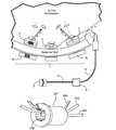
- FIG. 1is a general schematic view of an exemplary surgical robotic system.
- FIGS. 1A and 1Bare front views of exemplary human-machine interfaces.
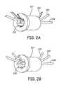
- FIGS. 2A and 2Bare perspective views of exemplary entrance ports.
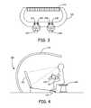
- FIG. 3is a perspective view of an exemplary surgeon console.
- FIG. 4is a side view of an exemplary surgeon console.
- FIG. 5is a side view of an exemplary patient table.
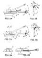
- FIGS. 6A and 6Bare side views showing 7-axis movement of an exemplary micro robotic manipulator.
- FIGS. 7A and 7Bare side views showing 7-axis movement of an exemplary micro robotic manipulator.
- FIG. 8Ais an end view and FIG. 8B is a side view of an exemplary foldable enclosure of a micro robotic manipulator.
- FIG. 9is a side view showing 2-axis movement of an exemplary 2D micro robotic camera.
- FIG. 10is a side view showing 2-axis movement of an exemplary 2D micro robotic camera.
- FIG. 11Ais an end view and FIG. 11B is a side view of an exemplary foldable enclosure of a micro robotic 2D-camera.
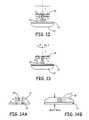
- FIG. 12is a side view showing 2-axis movement of an exemplary 3D micro robotic camera.
- FIG. 13is a side view showing 2-axis movement of an exemplary 3D micro robotic camera.
- FIG. 14Ais an end view and FIG. 14B is a side view of an exemplary foldable enclosure of a micro robotic 3D-camera.
- FIG. 15is a perspective view of an exemplary 3D micro robotic camera.
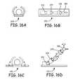
- FIG. 16Ais an end view of an exemplary micro robotic actuator in a folded configuration.
- FIG. 16Bis a side view of an exemplary micro robotic actuator in a folded configuration.
- FIG. 16Cis an end view of an exemplary micro robotic actuator in an unfolded configuration.
- FIG. 16Dis a side view of an exemplary micro robotic actuator in an unfolded state.
- FIG. 17is a side view of an exemplary micro robotic manipulator in an in vivo environment.
- FIGS. 18A and 18Bare side views of an exemplary micro robotic manipulator in an in vivo environment.
- FIG. 19is a schematic view of an exemplary surgical robotic system including a fine metal wire.
- FIGS. 20A and 20Bare front views of exemplary human machine interfaces.
- FIG. 21is a side view showing insertion of an exemplary fine metal wire.
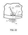
- FIG. 22is a side view showing locking of an exemplary fine metal wire to a miniature robot.
- FIG. 23is a side view showing an example of force of tightening by a fine metal wire.
- FIG. 24is a side view showing exemplary X-Y movement of a micro robotic manipulator to the left with a fine metal wire.
- FIG. 25is a side view showing exemplary X-Y movement of a micro robotic manipulator to the right with a fine metal wire.
- FIG. 26is a side view showing exemplary X-Y movement of a micro robotic manipulator to the left without a fine metal wire.
- FIG. 27is a side view showing exemplary X-Y movement of a micro robotic manipulator to the right without a fine metal wire.
- FIG. 28is side view of an exemplary intra abdominal mechanical frame.
- a Magnetic-anchored Robotic Systemallows computer-assisted minimally-invasive surgery using multiple independent in-vivo miniature robots that can have a full seven-degrees of freedom of movement in different axis (note that in addition to the degrees of freedom of movement of the miniature robots discussed below, two more degrees of freedom are available by translating the miniature robots along the abdominal wall).
- Intra-abdominal operationscan be performed under the surveillance of an in-vivo swivel camera under remote control by the surgeon through an external computer console.
- Each of the miniature robotic instruments, camera and other devicesmay be inserted into the abdominal cavity via either a single incision (for example, through the umbilicus) or through a natural orifice and may be secured into position by an external electro-magnetic anchoring and positioning device outside the abdominal wall at selected sites to provide operative ergonomics and triangulation between camera and instruments.
- the control of such miniature robotic system inside the abdominal cavitycan be, for example, via a wired or a hybrid combination of wired and wireless communications, depending on the situation and the condition of the patient.
- powerwill be transmitted to the miniature robotic instruments (effectors), by a pair of conductors, while the control signals of the same can be transmitted by wire or wirelessly.
- MRScan therefore allow MIS to be performed with the benefits of both computer-assisted or robotic surgery, as well as using either only a single incision or through a natural orifice (NOTES).
- An exemplary MRSmay include:
- exemplary advantagesincluding minimized access trauma, provision of unrestricted or less restricted and more dexterous movement of instruments inside the cavity and enabling proper or improved triangulation of instruments for optimal or improved operative ergonomics can be achieved.
- the systemmay include one or more magnetic or electromagnetic location fixing device(s) 1 (hereafter collectively referred to as the electromagnetic location fixing device 1 , which includes examples including permanent/non-electric magnets unless otherwise specifically excluded) placed on the outer abdominal wall associated with remotely controlled robotic manipulator(s) 2 inside the body.
- the electromagnetic location fixing device 1may include a servo mechanism that is remotely controlled to control the position of the internal electromagnetic anchoring device.
- the robotic manipulator inside the human bodycan therefore be moved and be positioned by an externally supplied magnetic field interacting with one or more permanent magnets or electromagnets included in the electromagnetic location fixing device 1 together with the internal electromagnetic anchoring device.
- Such an externally supplied magnetic fieldmay be moved by a X-Y servo mechanism to a designated position thus relocating the robotic arm 24 to the designated position and then refix again as shown in FIGS. 18 .
- the electromagnetic location fixing device 23 shown in FIG. 17may be in the form of a linear induction stator on the outside of the abdominal wall such that when an alternating current of appropriate frequency is applied to the stator on the outside of the abdominal wall, the inside flap 24 will levitate and move forward. When such an alternating current is applied in pulse form, the inside flap 24 will move forward in small steps.
- controlmay also be provided by a control computer .
- each location fixing deviceis shown with one robotic manipulator; however, there may be multiple robotic manipulators for one location fixing device or multiple location fixing devices for one robotic manipulator.
- each devicemay detect the current position of the end effector of the corresponding multi-axis micro robotic manipulator 2 inside the human body.
- the multi-axis micro robotic manipulator 2 inside the bodymay detect the current position of the end effector.
- the micro robotic manipulator 2may include various end effectors such as a gripping device 16 (for example, as shown in FIGS. 6 ) and an imaging device 3 for performing a given treatment and visualizing the in vivo environment respectively.
- the manipulator 2can be folded and inserted into the body cavity through an entrance port 7 in the form of a hollow cylinder mounted on a minimal invasive opening or the like of the patient. It may be connected to a flexible cable 4 passing through the entrance port 7 and linked to a central control computer 8 via an electrical wire 5 or wirelessly.
- the entrance port 7is in the range of 1.5-2 cm in diameter in some examples but may vary. The range of 1.5-2 cm is advantageous as it is big enough for equipment (manipulators, etc) to pass through and small enough to be accommodated by most natural orifices.
- the entrance ports 207 ′ and 207 ′′may be shaped to accommodate flexible cables 204 ′ and 204 ′′ in a manner that permits multiple of the manipulators 2 to be inserted through the same single entrance port 207 .
- An inner wall of the entrance ports 207 ′ and 207 ′′includes one or more recesses of a shape complementary to the wires 204 ′ and 204 ′′.
- the recesses 208 ′ in the inner wall of the entrance port 207 ′are slot shaped and include a flat surface to accommodate the flat cable 204 ′.
- a cross section of the inner wallmay be in the shape of a polyhedron having the recesses 208 ′ immediately joining an adjacent recess 208 ′.
- the recesses 208 ′may be distributed circumferentially about the inner surface of the entrance port 207 ′.
- the recesses 208 ′may be distributed equally or unequally about the inner surface of the entrance port 207 ′.
- the recesses 208 ′′ in the inner wall of the entrance port 207 ′′are rounded to accommodate the round cable 204 ′′.
- the recesses 208 ′′immediately join an adjacent recess 208 ′′.
- the recesses 208 ′′may be distributed circumferentially about the inner surface of the entrance port 207 ′′.
- the recesses 208 ′′may be distributed equally or unequally about the inner surface of the entrance port 207 ′′.
- the above described shapesare exemplary in nature and can be selected form a variety of other shapes according to a particular implementation.
- Providing the recesses 208allows for the use of the same entrance port for many of the manipulators 2 by clearing the opening of the entrance port 207 of the cables 204 to allow passage of another manipulator 2 . In this way, trauma associated with the insertion of entrance ports, trocars, etc, can be minimized by reusing the same single entrance port for several or all of the manipulators 2 .
- the signal transmission between the remotely controlled micro robotic manipulator 2 and the central control computer 8can be performed through a wired connection (for example, via the entrance port 7 over a conductive cable or an optical cable) or a wireless connection (for example, via inductive coupling with a pickup coil incorporated in the location fixing device as shown in device 1 a ).
- Power for the manipulator 2may also be supplied via the location fixing device 1 wirelessly through the abdominal wall.
- a hybridsuch as a wired power supply and wireless control signal may also be used.
- electromagnetic location fixing device 1may communicate wirelessly with the micro robotic manipulator 2 , which is connected to the central control computer 8 through a wired connection, for example via the entrance port 7 , to provide communication between the electromagnetic location fixing device 1 and the central control computer 8 .
- the central control computer 8may control positioning servos of the electromagnetic location fixing device 1 as well as activating/de-activating a fixing control.
- the fixing controlmay be, for example, activating an electromagnet in the electromagnetic fixing device 1 .
- the fixing controlis not necessarily a discrete on/off control and may also be variable.
- the central control computer 8can adjust the positions and actions of the manipulators 2 independently of each other by the corresponding movement of the trigger unit 10 b . 11 b controlled by an operator through a human machine interface 9 connecting to the controller via a cable 6 .
- the interface 9may include a display screen 10 a . 11 a and a pair of trigger units 10 b . 11 b , which may be different types such as the remote operation type 10 shown in FIG. 1A and multi-axis end-effector simulator type 11 shown in FIG. 1B .
- the trigger unit 11 bhas a multi-axis robotic joint that can provide fine position control of the end effector of the manipulator 2 with several degrees of freedom.
- the movement controlcan also include force feedback.
- the number of inserted miniature robotsis not limited to the number that can be controlled by one operator through the human machine interface 9 .
- a second human machine interfacemay be provided for an assistant operator to also control miniature robots if needed for the operation.
- a main surgeon 100controls a pair of controls 102 while an assistant 104 working on the same surgeon console 106 or another surgeon console controls additional controls 108 .
- the main surgeon 100 and/or the assistant 104may also control various cameras.
- the main surgeon 100 and the assistant 104can view the same display 110 or they may view separate displays, for example, showing different views of the patient.
- the display 110may be a 2D display, a 3D display, a naked eye 3D display, or other type of suitable display.
- the assistant 104may simultaneously operate and assist in the operation. Two or more operators may advantageously work on the same patient at the same time while maintaining dialog with each other. It will be appreciated that while a main surgeon and an assistant surgeon have been described, the console 106 may be operated by any one or two (or more) operators generically.
- the surgeon console 106may be ergonomically arranged including one or more of the foot rest 114 , the arm rest 116 and the seat 118 .
- the foot rest 114may incorporate switches to switch the controls 102 (and/or the controls 108 ) to control the camera instead of the manipulators/robots or vice-versa.
- the foot rest 114may also incorporate controls to control manual focusing of the camera(s).
- the foot rest 114 , arm rest 116 , controls 102 , controls 108 and/or any combination thereofmay include sensors to detect the presence of the operator in order to enable/disable the robotic system.
- the surgeon console 106may also be arranged to avoid light reflection.
- the display 110may be positioned such that at least a portion is below a height of the table 120 at which the surgeon sits.
- the display 110may also be angled such that reflections are not passed or reduced to the viewer at the table 120 .
- the light shelter 122may also be provided to reduce ambient lighting that may could cause reflections.
- Haptic feedbackmay be provided to the main surgeon 100 and/or the assistant 104 .
- a resisting forcemay be measured by the in-vivo robotic manipulator 2 , for example via an onboard sensor such as a load cell.
- the resisting forcemay also be estimated from an amount of energy (e.g., voltage, current or power) used by the manipulator 2 .
- Force feedback based on the resisting forcemay be provided to the main surgeon 100 and/or the assistant 104 via the manipulators 102 and 108 respectively.
- a plurality of the electromagnetic location fixing devices 1may be coupled to arms 132 .
- the arms 132may be secured or coupled to the gantry 134 , which is secured or coupled to the table 130 .
- the whole systemmay move simultaneously with the patient. This allows for the changing of the position of the patient intra-operatively without the need to undock the robotic system from the patient and operations that require changes in patient position during the surgical procedure are facilitated.
- the arms 132may be servo driven for repositioning or adjusting an orientation of the electromagnetic location fixing devices 1 .
- the axis of movement of the micro robotic manipulator 2may have several different types of configurations.
- 7-axis movementis shown.
- the joint 13can rotate along the axes I and II, and the arm 14 can translate along direction III.
- the wrist 15can rotate along axis IV, bend along axis V and bend along axis VI.
- a gripper/end effector 16may also open and close along the axis VII, which could include rotational and/or translational movement.
- a portion of the micro robotic manipulator 2 having a joint with rotational axis similar to that of joint 13 and axes I and 2 as shown in FIGS. 6is referred to as Type A as a matter of convenience and is non-limiting.
- FIGS. 7A and 7Bshow another configuration of the 7-axis movement of the manipulator 2 in which joint 13 rotates along axis I in another direction.
- a portion of the micro robotic manipulator 2 having a joint with rotational axis similar to that of joint 13 and axes I and II as shown in FIGS. 7is referred to as Type B as a matter of convenience and is non-limiting.
- the enclosure of the manipulator 2may facilitate the insertion of the manipulator into the body and protect the robotic arm and end effector inside the manipulator during insertion. It may include a base 21 and a pair of foldable flaps 17 on both sides of the base 21 . As a non-limiting example, the flaps 17 may have a maximum diameter of 18 mm in a folded configuration. A maximum diameter of 18 mm is advantageous as it works well with an entrance port sized for use with most natural orifices.
- the flapsare folded as shown in FIGS. 8 .
- the flaps 17may be unfolded by a magnetic force triggered from the corresponding electromagnetic location fixing device 1 .
- the unfolding of the flaps 17may be triggered by heat of the abdominal wall, by external radiation or by externally supplied power.
- the base 21may include a heating device activated by the supply of electrical current or by reception of a radiative energy from a transmitter included in the electromagnetic location fixing device 1 .
- the coolingmay be effected by removing the electrical current or transmitted radiation supplied to the heating device and/or separating the manipulator 2 from the abdominal wall.
- the heating and coolingcan also be achieved by other methods such as a thermo-electric heater/cooler, heat pipes, etc. This operation may be reversed with folding being triggered by heating and unfolding being triggered by cooling.
- the flaps 17may be a laminate of two materials having different coefficients of thermal expansion. Thus, as the flaps 17 are heated and cooled, the materials expand and contract at different rates causing the flaps 17 to fold and unfold.
- the materialsmay be metal alloys.
- the flaps 17may be constructed from a shape memory alloy.
- the flaps 17may be re-folded by manipulating the flaps 17 using another manipulator.
- the flaps 17may have a spring effect to assist in opening or closing the flaps and holding the flaps folded.
- the flaps 17may have a spring effect with a resultant force that tends to fold the flaps 17 .
- the spring effectis not strong enough to hold the flaps 17 folded and the flaps 17 are unfolded by the magnetic force.
- the spring effectmay cause the flaps 17 to fold.
- translation motion of the flaps 17may be provided by rollers on the flaps 17 (for example as shown by flaps 24 in FIGS. 18 ) that are magnetically switchable or electrically actuatable.
- Translation motion of the manipulator 2may be provided by electromagnetic levitation.
- the attractive force between the manipulator 2 and the electromagnetic location fixing device 1may be lessened or reversed to permit movement with respect to the abdominal wall.
- the electromagnetic location fixing device 1may then be moved on the abdominal wall by a servo or magnetic transport (similar to the electromagnetic fixing device 26 and base 25 shown in FIGS. 18 ).
- magnetsmay be provided in the electromagnetic location fixing device 1 .
- An externally supplied magnetic fieldis supplied to interact with the magnets of the electromagnetic location fixing device 1 or 26 to cause the electromagnetic location fixing device 1 to move in an X-Y direction and be repositioned with respect to the abdominal wall.
- the end effector of the manipulator 2may be adapted to a gripping device 16 , an imaging device, such as a 2D video camera 18 or a 3D stereoscopic video camera 19 , or other devices.
- an imaging devicesuch as a 2D video camera 18 or a 3D stereoscopic video camera 19
- the cameramay rotate along two perpendicular axes to acquire a 2D planar or 3D stereoscopic view in different orientations. Examples of two different types of configurations are shown in FIGS. 9 and 12 (Type A) and FIGS. 10 and 13 (Type B).
- the enclosure of the cameramay facilitate the insertion of the manipulator into the body and protect the 2D camera or 3D camera inside the manipulator during insertion.
- the flapsare folded as shown in FIGS. 11 and FIGS. 14 respectively.
- the flapsmay have a maximum diameter of 18 mm.
- a maximum diameter of 18 mmis advantageous us as it works well with an entrance port sized for use with most natural orifices.
- the flaps 17are unfolded by a magnetic force triggered from the corresponding remotely controlled electromagnetic location fixing device 1 .
- a spring loaded rotational joint 20may be included for a 3D camera, as shown in FIG. 13 .
- FIG. 15is a perspective view of an exemplary 3D camera 150 .
- the camera 150may include 3 parts: a camera body 152 , an extendable linkage bar 154 and a foldable magnetic anchorage 156 .
- the camera body 150may include a swivel head 158 and two camera lenses 160 .
- the camera lenses 160may be spaced apart along a major axis of the swivel head 158 and provide a 3D image.
- the major axis of the swivel headmay coincide with a longitudinal axis of the camera 150 in its folded configuration. Spacing the camera lens along the longitudinal axis or “side” accommodates both of the camera lenses 160 , thereby providing 3D imagery not otherwise possible, in the limited diameter available in the implantable device.
- the swivel head 158can swing approximately 90 degrees (or more) to allow the “side” looking cameras to look forward.
- a flexible linkage 162which may be a hinge, is linked to a body part 164 , which may be a tube or tube-like control unit.
- the body part 164is linked to the extendable linkage bar 154 via a flexible linkage 166 , which may be a hinge.
- the extendable linkage bar 154extends and retracts to allow positioning of the camera body 152 near to the surgical field.
- An opposite end of the extendable linkage bar 154is linked, and in some cases locked, to the foldable magnetic anchorage 156 , for example, through a 2-axis flexible linkage 168 a and 168 b .
- the flexible linkages 162 , 166 , 168 a and 168 bmay be servo driven.
- the foldable magnetic anchorage 156may be secured on the abdominal/body wall, for example by activating an external magnet or positioning a permanent magnet outside the abdominal wall.
- the flexible linkages 162 and 166allow the camera 150 to bend and position in difficult and confined spaces while being secured by the anchorage 156 .
- the foldable magnetic anchorage 156may also be swiveled slightly with a center of rotation at the abdominal wall, for example by swiveling the external magnetic anchor, to facilitate slight sideway movement of the camera for clearer vision of an area of interest.
- FIGS. 16show an exemplary micro robotic actuator 170 having 7 degrees of freedom and multiple axis of movement provided by the joints 172 , 174 , 178 and 180 .
- Additional anchoring forcemay be provided to the electromagnetic location fixing device 1 .
- an obese patient with a thick abdominal walle.g., 50 mm thick or more
- space available to accommodate the manipulators 2 having a small profileis limited.
- providing for external actuationmay be desirable to provide sufficient torque for seven full axes of movement in the gripping and moving of organs or tissues during a surgical operation.
- a flexible or semi-flexible magnetic sheet 22can be inserted into the body cavity through the entrance port 7 .
- the magnetic sheet 22may be rolled or folded. Once inserted, it can be unfolded or unrolled and positioned along the abdominal wall.
- the magnetic sheet 22may be unfolded/unrolled by a mechanical mechanism or it may be unfolded/unrolled by subjecting it to a magnetic field, which may be supplied by an external electromagnet, and/or by heating or cooling through supplied energy.
- the magnetic sheet 22may be provided as a single large sheet sufficient to cover a large area of the inner abdominal wall.
- the magnetic sheetmay also be provided by one or more small or medium sized sheets to provide coverage for a certain region of the abdominal wall.
- An intra abdominal mechanical framefor example the intra abdominal mechanical frame 27 shown in FIG. 28 , may be constructed by linking individual magnetic sheets with extendable bars to provide a stable platform for the miniature robots to operate.
- This intra abdominal mechanical framemay, in some cases, provide anchoring support similar to that of a large flexible magnetic sheet covering a large part of the abdomen without requiring the use of such a large sheet.
- the position of the magnetic sheet 22may be fixed by the external electromagnet 1 b .
- the magnetic sheet 22provides a stable platform for the micro robotic manipulator 2 to attach to.
- the magnetic sheet 22may provide a medium to concentrate magnetic flux and provide for the secure anchorage of micro robotic manipulators such as the micro robotic manipulator 2 .
- Exemplary materials that provide such a medium to concentrate fluxinclude iron and silicon-iron based materials. It will be appreciated that this secure anchorage can be provided for any micro robotic manipulator as well as other related devices such as a camera. It will also be appreciated that the magnetic sheet may be used with, but is not required for, any of the described examples including those of FIGS. 1 and 17 - 28 .
- a fine wire 28may be included.
- the fine wire 28which may be a metal wire, extends from the external electromagnet 1 b and may be introduced through the abdominal wall via, or in the form of, a fine needle.
- the wire 28may have a maximum diameter of 1 mm. A maximum diameter of 1 mm is preferable so that punctures remain well below a size that would be regarded an incision and leave no significant visible scarring. It will be appreciated that other materials such as flexible or rigid fibers, biocompatible polymers/plastics and multi-material composites that may or may not include a metal may be used in place of metal for the wire 28 .
- the fine metal wire 28may be provided from the external electromagnet 1 b via a circular through hole, a slot, or another aperture in the electromagnet 1 b .
- the hole, slot or other aperturemay be provided at a center of the electromagnet 1 b.
- a locking mechanismsuch as a pair of inclined metal tabs having a separation less than a thickness of the fine wire 28 or a tip thereof, may be provided to releasably lock the micro manipulator 2 on the tip of the fine wire 28 .
- the metal tabmay be subject to a biasing force, such as a spring, to keep the fine wire 28 locked in the micro robotic manipulator 2 . Removing the biasing force or providing a counter force may allow the fine wire 28 to be released.
- the release of the fine wire 28may be provided by a remote controlled electrical actuator or by mechanical action, for example by an endoscope, inside the abdomen.
- the tip of the metal wire 28may be locked by a releasable non-return mechanism.
- the tip of the fine wire 28may be enlarged to provide a more secure lock.
- An aperturemay be provided in the external electromagnet 1 b through which the fine wire 28 passes.
- the aperturemay be in the form of a slot, a cross, a large singular opening, or another shape. Providing the aperture allows for the relocation of the micro robotic manipulator 2 after the fine wire 28 has been inserted in the abdominal wall without requiring a reinsertion of the fine wire 28 .
- the wiremay be loosened allowing the movement of the external electromagnet 1 b and the micro robotic manipulator 2 and subsequently retightened to allow for the repositioning of the micro robotic manipulator 2 .
- the fine wire 28may also be used to supply power or signals to/from the micro robotic manipulator 2 .
- movement of the micro robotic manipulator 2may be induced by the swivel action of external electromagnet 1 b .
- the center of movementmay be located at the midpoint of the abdominal wall.
- the external actuationcan supplement the X-Y movement of micro-actuator on the micro robotic manipulator 2 . Due to the leverage effect, a small angular movement of the electromagnet 1 b will lead to a large two dimensional X-Y movement of the micro robotic manipulator 2 . Without the tight coupling, attempts to move the micro robotic manipulator 2 in this manner would likely result in separation of the micro robotic manipulator 2 and the external electromagnet 1 b and X-Y movement would not be achieved.
Landscapes
- Health & Medical Sciences (AREA)
- Surgery (AREA)
- Life Sciences & Earth Sciences (AREA)
- Engineering & Computer Science (AREA)
- General Health & Medical Sciences (AREA)
- Public Health (AREA)
- Heart & Thoracic Surgery (AREA)
- Medical Informatics (AREA)
- Molecular Biology (AREA)
- Animal Behavior & Ethology (AREA)
- Nuclear Medicine, Radiotherapy & Molecular Imaging (AREA)
- Biomedical Technology (AREA)
- Veterinary Medicine (AREA)
- Robotics (AREA)
- Pathology (AREA)
- Human Computer Interaction (AREA)
- Mechanical Engineering (AREA)
- Oral & Maxillofacial Surgery (AREA)
- Manipulator (AREA)
- Surgical Instruments (AREA)
Abstract
Description
Claims (13)
Priority Applications (8)
| Application Number | Priority Date | Filing Date | Title |
|---|---|---|---|
| US13/835,680US8891924B2 (en) | 2012-04-26 | 2013-03-15 | Magnetic-anchored robotic system |
| US13/871,926US9020640B2 (en) | 2012-04-26 | 2013-04-26 | Magnetic-anchored robotic system |
| HK14107459.3AHK1193966B (en) | 2012-04-26 | 2013-04-26 | Magnetic-anchored robotic system |
| EP13780598.2AEP2840977A4 (en) | 2012-04-26 | 2013-04-26 | Magnetic-anchored robotic system |
| PCT/CN2013/000478WO2013159572A1 (en) | 2012-04-26 | 2013-04-26 | Magnetic-anchored robotic system |
| IN8945DEN2014IN2014DN08945A (en) | 2012-04-26 | 2013-04-26 | |
| CN201380001233.7ACN103533898B (en) | 2012-04-26 | 2013-04-26 | Magnetically anchored robotic system |
| US14/927,048US10179033B2 (en) | 2012-04-26 | 2015-10-29 | Magnetic-anchored robotic system |
Applications Claiming Priority (3)
| Application Number | Priority Date | Filing Date | Title |
|---|---|---|---|
| US201261638828P | 2012-04-26 | 2012-04-26 | |
| US201261718252P | 2012-10-25 | 2012-10-25 | |
| US13/835,680US8891924B2 (en) | 2012-04-26 | 2013-03-15 | Magnetic-anchored robotic system |
Publications (2)
| Publication Number | Publication Date |
|---|---|
| US20130289580A1 US20130289580A1 (en) | 2013-10-31 |
| US8891924B2true US8891924B2 (en) | 2014-11-18 |
Family
ID=49477932
Family Applications (4)
| Application Number | Title | Priority Date | Filing Date |
|---|---|---|---|
| US13/835,680ActiveUS8891924B2 (en) | 2012-04-26 | 2013-03-15 | Magnetic-anchored robotic system |
| US13/835,653Active2033-06-15US9789613B2 (en) | 2012-04-26 | 2013-03-15 | Magnetic-anchored robotic system |
| US13/871,915ActiveUS10065323B2 (en) | 2012-04-26 | 2013-04-26 | Magnetic-anchored robotic system |
| US13/871,926Expired - Fee RelatedUS9020640B2 (en) | 2012-04-26 | 2013-04-26 | Magnetic-anchored robotic system |
Family Applications After (3)
| Application Number | Title | Priority Date | Filing Date |
|---|---|---|---|
| US13/835,653Active2033-06-15US9789613B2 (en) | 2012-04-26 | 2013-03-15 | Magnetic-anchored robotic system |
| US13/871,915ActiveUS10065323B2 (en) | 2012-04-26 | 2013-04-26 | Magnetic-anchored robotic system |
| US13/871,926Expired - Fee RelatedUS9020640B2 (en) | 2012-04-26 | 2013-04-26 | Magnetic-anchored robotic system |
Country Status (5)
| Country | Link |
|---|---|
| US (4) | US8891924B2 (en) |
| EP (2) | EP2840990A4 (en) |
| CN (3) | CN103582462B (en) |
| IN (2) | IN2014DN08947A (en) |
| WO (2) | WO2013159572A1 (en) |
Cited By (8)
| Publication number | Priority date | Publication date | Assignee | Title |
|---|---|---|---|---|
| US9724168B2 (en) | 2014-04-22 | 2017-08-08 | Bio-Medical Engineering (HK) Limited | Robotic devices and systems for performing single incision procedures and natural orifice translumenal endoscopic surgical procedures, and methods of configuring robotic devices and systems |
| US9855108B2 (en) | 2014-04-22 | 2018-01-02 | Bio-Medical Engineering (HK) Limited | Robotic devices and systems for performing single incision procedures and natural orifice translumenal endoscopic surgical procedures, and methods of configuring robotic devices and systems |
| US9895200B2 (en) | 2014-04-22 | 2018-02-20 | Bio-Medical Engineering (HK) Limited | Robotic devices and systems for performing single incision procedures and natural orifice translumenal endoscopic surgical procedures, and methods of configuring robotic devices and systems |
| US10179033B2 (en) | 2012-04-26 | 2019-01-15 | Bio-Medical Engineering (HK) Limited | Magnetic-anchored robotic system |
| US10817060B2 (en)* | 2016-11-29 | 2020-10-27 | Preh Gmbh | Method and arrangement for manufacturing a control device offering haptic feedback |
| US11090123B2 (en) | 2014-04-22 | 2021-08-17 | Bio-Medical Engineering (HK) Limited | Robotic devices and systems for performing single incision procedures and natural orifice translumenal endoscopic surgical procedures, and methods of configuring robotic devices and systems |
| US11154368B2 (en) | 2014-04-22 | 2021-10-26 | Bio-Medical Engineering (HK) Limited | Port assembly for use with robotic devices and systems to perform single incision procedures and natural orifice translumenal endoscopic surgical procedures |
| US11801099B2 (en) | 2014-04-22 | 2023-10-31 | Bio-Medical Engineering (HK) Limited | Robotic devices and systems for performing single incision procedures and natural orifice translumenal endoscopic surgical procedures, and methods of configuring robotic devices and systems |
Families Citing this family (68)
| Publication number | Priority date | Publication date | Assignee | Title |
|---|---|---|---|---|
| US9789608B2 (en) | 2006-06-29 | 2017-10-17 | Intuitive Surgical Operations, Inc. | Synthetic representation of a surgical robot |
| US10258425B2 (en) | 2008-06-27 | 2019-04-16 | Intuitive Surgical Operations, Inc. | Medical robotic system providing an auxiliary view of articulatable instruments extending out of a distal end of an entry guide |
| US9718190B2 (en) | 2006-06-29 | 2017-08-01 | Intuitive Surgical Operations, Inc. | Tool position and identification indicator displayed in a boundary area of a computer display screen |
| US10008017B2 (en) | 2006-06-29 | 2018-06-26 | Intuitive Surgical Operations, Inc. | Rendering tool information as graphic overlays on displayed images of tools |
| US12357400B2 (en) | 2006-06-29 | 2025-07-15 | Intuitive Surgical Operations, Inc. | Synthetic representation of a surgical robot |
| US9089256B2 (en) | 2008-06-27 | 2015-07-28 | Intuitive Surgical Operations, Inc. | Medical robotic system providing an auxiliary view including range of motion limitations for articulatable instruments extending out of a distal end of an entry guide |
| US9469034B2 (en)* | 2007-06-13 | 2016-10-18 | Intuitive Surgical Operations, Inc. | Method and system for switching modes of a robotic system |
| US8620473B2 (en) | 2007-06-13 | 2013-12-31 | Intuitive Surgical Operations, Inc. | Medical robotic system with coupled control modes |
| CA2706860C (en) | 2007-11-26 | 2017-08-01 | Eastern Virginia Medical School | Magnaretractor system and method |
| US12239396B2 (en) | 2008-06-27 | 2025-03-04 | Intuitive Surgical Operations, Inc. | Medical robotic system providing an auxiliary view including range of motion limitations for articulatable instruments extending out of a distal end of an entry guide |
| CL2009000279A1 (en) | 2009-02-06 | 2009-08-14 | Biotech Innovations Ltda | Remote guidance and traction system for mini-invasive surgery, comprising: at least one surgical and removable endopinza with hooking means and a portion of ferro-magnaetic material, a cylindrical introduction guide, a detachment mechanism, and at least a means of remote traction with magnet. |
| US12266040B2 (en) | 2009-03-31 | 2025-04-01 | Intuitive Surgical Operations, Inc. | Rendering tool information as graphic overlays on displayed images of tools |
| US9492927B2 (en) | 2009-08-15 | 2016-11-15 | Intuitive Surgical Operations, Inc. | Application of force feedback on an input device to urge its operator to command an articulated instrument to a preferred pose |
| KR101731969B1 (en)* | 2010-12-03 | 2017-05-02 | 삼성전자주식회사 | Surgical instrument |
| US9956042B2 (en) | 2012-01-13 | 2018-05-01 | Vanderbilt University | Systems and methods for robot-assisted transurethral exploration and intervention |
| US9687303B2 (en) | 2012-04-20 | 2017-06-27 | Vanderbilt University | Dexterous wrists for surgical intervention |
| US9539726B2 (en)* | 2012-04-20 | 2017-01-10 | Vanderbilt University | Systems and methods for safe compliant insertion and hybrid force/motion telemanipulation of continuum robots |
| WO2013158983A1 (en) | 2012-04-20 | 2013-10-24 | Vanderbilt University | Robotic device for establishing access channel |
| US9333650B2 (en) | 2012-05-11 | 2016-05-10 | Vanderbilt University | Method and system for contact detection and contact localization along continuum robots |
| US10507066B2 (en) | 2013-02-15 | 2019-12-17 | Intuitive Surgical Operations, Inc. | Providing information of tools by filtering image areas adjacent to or on displayed images of the tools |
| US8764769B1 (en) | 2013-03-12 | 2014-07-01 | Levita Magnetics International Corp. | Grasper with magnetically-controlled positioning |
| US10010370B2 (en) | 2013-03-14 | 2018-07-03 | Levita Magnetics International Corp. | Magnetic control assemblies and systems therefor |
| WO2015112645A1 (en) | 2014-01-21 | 2015-07-30 | Levita Magnetics International Corp. | Laparoscopic graspers and systems therefor |
| US10500008B2 (en) | 2014-04-22 | 2019-12-10 | Bio-Medical Engineering (HK) Limited | Surgical arm system with internally driven gear assemblies |
| US9827058B1 (en) | 2016-11-01 | 2017-11-28 | Bio-Medical Engineering (HK) Limited | Surgical robotic devices and systems for use in performing minimally invasive and natural orifice transluminal endoscopic surgical actions |
| CN105358072B (en) | 2014-04-22 | 2018-11-09 | 香港生物医学工程有限公司 | Single access channel surgical robotic devices and systems and methods of configuring single access channel surgical robotic devices and systems |
| CN103976792B (en)* | 2014-06-04 | 2016-03-23 | 哈尔滨工业大学 | Self-cleaning and tilt-adjustable transmission mechanism for an intraperitoneal vision robotic cell |
| CN104055548B (en)* | 2014-07-10 | 2016-03-02 | 张自雄 | The device that chamber is suitable for cervical region endoscopic surgery is built by Magnetic force tracting activity |
| CN106687062B (en)* | 2014-09-17 | 2019-11-22 | 直观外科手术操作公司 | System and method for controlling movement of manipulator joints using augmented Jacobian matrix |
| CN104706417B (en)* | 2015-02-03 | 2017-05-10 | 首都医科大学附属北京友谊医院 | Magnetically fixed suspension type single port laparoscopic surgery robot system |
| ES2895900T3 (en) | 2015-04-13 | 2022-02-23 | Levita Magnetics Int Corp | Magnetically controlled location handle |
| WO2016168377A1 (en)* | 2015-04-13 | 2016-10-20 | Levita Magnetics International Corp. | Retractor systems, devices, and methods for use |
| SG11201805324SA (en)* | 2015-04-22 | 2018-07-30 | Bio Medical Eng Hk Ltd | Robotic devices and systems for performing single incision procedures and natural orifice translumenal endoscopic surgical procedures, and methods of configuring robotic devices and systems |
| US10070854B2 (en) | 2015-05-14 | 2018-09-11 | Ankon Medical Technologies (Shanghai), Ltd. | Auxiliary apparatus for minimally invasive surgery and method to use the same |
| JP6786531B2 (en)* | 2015-07-03 | 2020-11-18 | オフソロボティクス アーゲー | Intraocular injection system |
| DE102015114742B4 (en)* | 2015-09-03 | 2017-06-14 | Imk Automotive Gmbh | Kinematics for an intracorporeally driven instrument of an endoscope |
| SG11201803509XA (en)* | 2015-10-29 | 2018-05-30 | Bio Medical Eng Hk Ltd | Magnetic-anchored robotic system |
| CN105326470B (en)* | 2015-11-30 | 2017-03-29 | 西安交通大学第一附属医院 | A kind of magnetic grappling laparoscope system based near infrared light visual diagnostic |
| EP3399902B1 (en) | 2016-01-08 | 2024-06-12 | Levita Magnetics International Corp. | One-operator surgical system |
| SG10201808087SA (en)* | 2016-11-01 | 2018-10-30 | Bio Medical Eng Hk Ltd | Robotic devices and systems for performing single incision procedures and natural orifice translumenal endoscopic surgical procedures, and methods of configuring robotic devices and systems |
| CA3022502A1 (en)* | 2016-11-01 | 2018-05-11 | Bio-Medical Engineering (HK) Limited | Robotic devices and systems for performing single incision procedures and natural orifice translumenal endoscopic surgical procedures, and methods of configuring robotic devices and systems |
| CN109893179B (en)* | 2016-11-01 | 2022-11-04 | 香港生物医学工程有限公司 | Surgical system for performing endoscopic procedures through a natural orifice |
| WO2018081931A1 (en)* | 2016-11-01 | 2018-05-11 | Bio-Medical Engineering (HK) Limited | Surgical robotic devices and systems for use in performing minimally invasive and natural orifice transluminal endoscopic surgical actions |
| CN107485415A (en)* | 2016-11-01 | 2017-12-19 | 香港生物医学工程有限公司 | Surgical system for performing natural translumenal endoscopic procedures |
| EP3576596A4 (en) | 2016-12-02 | 2021-01-06 | Vanderbilt University | STEERABLE ENDOSCOPE WITH CONTINUOUS MANIPULATOR |
| DE102017103199A1 (en)* | 2017-02-16 | 2018-08-16 | avateramedical GmBH | HMI device for a robot-assisted surgical system |
| US11020137B2 (en) | 2017-03-20 | 2021-06-01 | Levita Magnetics International Corp. | Directable traction systems and methods |
| US10967504B2 (en) | 2017-09-13 | 2021-04-06 | Vanderbilt University | Continuum robots with multi-scale motion through equilibrium modulation |
| WO2019204116A1 (en)* | 2018-04-19 | 2019-10-24 | Terumo Cardiovascular Systems Corporation | Flexible camera system for minimally invasive surgery |
| CN108969032B (en)* | 2018-07-09 | 2020-11-24 | 南京航空航天大学 | A linear-rotation-swing three-degree-of-freedom magnetic laparoscopic mechanism |
| CN109124555B (en)* | 2018-07-09 | 2020-11-17 | 南京航空航天大学 | Straight line-swing three-degree-of-freedom magnetic attraction type laparoscope mechanism |
| EP3820378A4 (en)* | 2018-07-12 | 2022-04-06 | Bionaut Labs Ltd. | MAGNETIC PROPULSION MECHANISM FOR MAGNETIC DEVICES |
| US12040131B2 (en) | 2018-11-05 | 2024-07-16 | Bionaut Labs Ltd. | Magnetic propulsion system for magnetic devices |
| CN109288549B (en)* | 2018-11-27 | 2021-03-16 | 上海安翰医疗技术有限公司 | Minimally invasive surgery auxiliary device and control method thereof |
| CN110101390B (en)* | 2019-06-03 | 2023-11-07 | 呜啦啦(广州)科技有限公司 | Joint bidirectional bending measuring device |
| CN110270978B (en)* | 2019-07-15 | 2020-11-10 | 哈尔滨工业大学 | A micro-nano robot control platform system under the action of multi-physics energy field coupling |
| CN112043325B (en)* | 2020-10-12 | 2021-10-01 | 天津市人民医院 | Magnetic pulling piece for body cavity surgery and working method |
| GB2600984B (en)* | 2020-11-16 | 2025-02-26 | Cmr Surgical Ltd | A base for supporting a surgical robot |
| US20240033020A1 (en)* | 2020-12-16 | 2024-02-01 | Robeaute | Delivery and gathering system comprising a microrobot |
| EP4066770A1 (en)* | 2021-04-02 | 2022-10-05 | Robeaute | Delivery and gathering system comprising a microrobot |
| CN113180831A (en)* | 2021-04-16 | 2021-07-30 | 南京航空航天大学 | Magnetic anchoring laparoscopic surgery robot |
| CN113262393B (en)* | 2021-04-23 | 2022-09-13 | 天津大学 | Flexible Magnetic Levitation Micro Centrifugal Pump |
| CN115674180B (en)* | 2021-07-27 | 2025-02-07 | 瑞龙诺赋(上海)医疗科技有限公司 | Control method, device, electronic device and storage medium |
| WO2023004814A1 (en) | 2021-07-30 | 2023-02-02 | 中国人民解放军总医院第一医学中心 | In vivo microrobot for nerve traction |
| CN114469356B (en)* | 2022-01-24 | 2023-09-15 | 重庆金山医疗机器人有限公司 | Driving method of master hand and surgical robot doctor control console |
| EP4547150A1 (en)* | 2022-07-01 | 2025-05-07 | Vicarious Surgical Inc. | Systems and methods for stereoscopic visualization in surgical robotics without requiring glasses or headgear |
| EP4629927A2 (en)* | 2022-12-08 | 2025-10-15 | Arizona Board of Regents on behalf of Arizona State University | System and method for magnetic manipulation of tissue |
| CN115867110B (en)* | 2023-02-21 | 2023-05-09 | 宁波大学 | Autonomous-searching type flexible piezoelectric micro-nano manipulator and preparation method thereof |
Citations (64)
| Publication number | Priority date | Publication date | Assignee | Title |
|---|---|---|---|---|
| US4278077A (en) | 1978-07-27 | 1981-07-14 | Olympus Optical Co., Ltd. | Medical camera system |
| US4289288A (en)* | 1978-10-02 | 1981-09-15 | The Boeing Company | Wire routing apparatus |
| US5566268A (en)* | 1995-05-30 | 1996-10-15 | The Whitaker Corporation | Strain relieving holder for optical fiber cable |
| US5604531A (en) | 1994-01-17 | 1997-02-18 | State Of Israel, Ministry Of Defense, Armament Development Authority | In vivo video camera system |
| US5675124A (en)* | 1996-04-30 | 1997-10-07 | Stough; Robert Eugene | Grommet for a fiber optic enclosure |
| US6078718A (en)* | 1996-06-18 | 2000-06-20 | Siecor Corporation | Strain relief device for plurality of optical ribbon fibers |
| US6133528A (en)* | 1997-09-09 | 2000-10-17 | Kimball International, Inc. | Cable management grommet |
| US6240312B1 (en) | 1997-10-23 | 2001-05-29 | Robert R. Alfano | Remote-controllable, micro-scale device for use in in vivo medical diagnosis and/or treatment |
| US6402686B1 (en) | 1999-06-07 | 2002-06-11 | Asahi Kogaku Kogyo Kabushiki Kaisha | Fully-swallowable endoscopic system |
| US20020103417A1 (en) | 1999-03-01 | 2002-08-01 | Gazdzinski Robert F. | Endoscopic smart probe and method |
| US20030020810A1 (en) | 2001-07-30 | 2003-01-30 | Olympus Optical Co., Ltd. | Capsule-type medical apparatus |
| US20030092964A1 (en) | 2001-11-12 | 2003-05-15 | Korea Institute Of Science And Technology | Micro capsule type robot |
| US20030114731A1 (en) | 2001-12-14 | 2003-06-19 | Cadeddu Jeffrey A. | Magnetic positioning system for trocarless laparoscopic instruments |
| US20030167000A1 (en) | 2000-02-08 | 2003-09-04 | Tarun Mullick | Miniature ingestible capsule |
| US6648814B2 (en) | 2001-04-24 | 2003-11-18 | Korean Institute Of Science And Technology | Micro-robot for colonoscope with motor locomotion and system for colonoscope using the same |
| US6702734B2 (en) | 2001-02-10 | 2004-03-09 | Korea Institute Of Science And Technology | Self-propelled endoscopic micro-robot and system for intestinal endoscopy using the same |
| US20040050395A1 (en) | 2002-09-13 | 2004-03-18 | Pentax Corporation | Magnetic anchor remote guidance system |
| US6729587B1 (en)* | 2002-05-31 | 2004-05-04 | Bellsouth Intellectual Property Corporation | Communication cable support for drop ceiling |
| US20040086238A1 (en)* | 2002-11-01 | 2004-05-06 | Itt Manufacturing Enterprises, Inc. | Fiber optic flat ribbon cable strain relief |
| US6776165B2 (en) | 2002-09-12 | 2004-08-17 | The Regents Of The University Of California | Magnetic navigation system for diagnosis, biopsy and drug delivery vehicles |
| US20040176664A1 (en) | 2002-10-29 | 2004-09-09 | Iddan Gavriel J. | In-vivo extendable element device and system, and method of use |
| JP2004321692A (en) | 2003-04-28 | 2004-11-18 | Pentax Corp | Magnetic anchor remote guidance system with gravity direction visual recognition device and endoscope treatment method using magnetic anchor remote guidance system with gravity direction visualization device |
| US20040256138A1 (en)* | 2003-06-18 | 2004-12-23 | Preformed Line Products Company, An Ohio Corporation | Fiber closure system |
| JP2005028006A (en) | 2003-07-10 | 2005-02-03 | Pentax Corp | Endoscope holding device and magnetic anchor remote guidance system |
| US20050029978A1 (en) | 2003-07-08 | 2005-02-10 | Dmitry Oleynikov | Microrobot for surgical applications |
| US20050096502A1 (en) | 2003-10-29 | 2005-05-05 | Khalili Theodore M. | Robotic surgical device |
| US20050165449A1 (en) | 2003-12-02 | 2005-07-28 | Board Of Regents, The University Of Texas System | Surgical anchor and system |
| US20050273139A1 (en) | 2004-06-01 | 2005-12-08 | Norbert Krauss | Device for clamping tissue |
| US20050288555A1 (en) | 2004-06-28 | 2005-12-29 | Binmoeller Kenneth E | Methods and devices for illuminating, vievwing and monitoring a body cavity |
| US6991627B2 (en) | 1996-05-20 | 2006-01-31 | Intuitive Surgical Inc. | Articulated surgical instrument for performing minimally invasive surgery with enhanced dexterity and sensitivity |
| US20060119304A1 (en) | 2003-07-08 | 2006-06-08 | Shane Farritor | Robot for surgical applications |
| US7066879B2 (en) | 2003-07-15 | 2006-06-27 | The Trustees Of Columbia University In The City Of New York | Insertable device and system for minimal access procedure |
| US20060149135A1 (en) | 2003-07-02 | 2006-07-06 | Adrian Paz | Virtual ports devices and method |
| US20060153516A1 (en)* | 2005-01-13 | 2006-07-13 | Napiorkowski John J | Network interface device having integral slack storage compartment |
| US7182089B2 (en) | 2003-09-19 | 2007-02-27 | Siemens Aktiengesellschaft | Magnetically navigable device with associated magnetic element |
| US20070123748A1 (en) | 2005-07-14 | 2007-05-31 | Dwight Meglan | Robot for minimally invasive interventions |
| JP2007143371A (en)* | 2005-11-22 | 2007-06-07 | Yazaki Corp | Grommet inner |
| US20070157937A1 (en) | 2006-01-11 | 2007-07-12 | Olympus Medical Systems Corp. | Medical procedure via natural opening |
| US20070255273A1 (en) | 2006-04-29 | 2007-11-01 | Board Of Regents, The University Of Texas System | Devices for use in Transluminal and Endoluminal Surgery |
| US7311107B2 (en) | 2001-04-18 | 2007-12-25 | Bbms Ltd. | Navigating and maneuvering of an in vivo vehicle by extracorporeal devices |
| CN101091665A (en) | 2007-07-12 | 2007-12-26 | 上海交通大学 | Endoscopic auxiliary manipulator for surgery of nasal cavity |
| WO2007149559A2 (en) | 2006-06-22 | 2007-12-27 | Board Of Regents Of The University Of Nebraska | Magnetically coupleable robotic devices and related methods |
| US20080058989A1 (en) | 2006-04-13 | 2008-03-06 | Board Of Regents Of The University Of Nebraska | Surgical camera robot |
| WO2008103212A2 (en) | 2007-02-20 | 2008-08-28 | Board Of Regents Of The University Of Nebraska | Methods, systems, and devices for surgical visualization and device manipulation |
| US20080249359A1 (en) | 2005-07-11 | 2008-10-09 | Klaus Abraham-Fuchs | Endoscopy System |
| WO2009014917A2 (en) | 2007-07-12 | 2009-01-29 | Board Of Regents Of The University Of Nebraska | Methods and systems of actuation in robotic devices |
| WO2009023851A1 (en) | 2007-08-15 | 2009-02-19 | Board Of Regents Of The University Of Nebraska | Modular and cooperative medical devices and related systems and methods |
| US20090171373A1 (en) | 2007-06-21 | 2009-07-02 | Farritor Shane M | Multifunctional operational component for robotic devices |
| US20090259340A1 (en) | 2008-04-15 | 2009-10-15 | Olympus Medical Systems Corp. | Manipulator and method of controlling manipulator |
| US7625338B2 (en) | 2003-12-31 | 2009-12-01 | Given Imaging, Ltd. | In-vivo sensing device with alterable fields of view |
| WO2010083480A2 (en) | 2009-01-16 | 2010-07-22 | The Board Of Regents Of The University Of Texas System | Medical devices and methods |
| US20100318059A1 (en) | 2003-07-08 | 2010-12-16 | Board Of Regents Of The University Of Nebraska | Robotic devices with agent delivery components and related methods |
| US20110087223A1 (en) | 2009-10-09 | 2011-04-14 | Spivey James T | Magnetic surgical sled with locking arm |
| US20110087224A1 (en) | 2009-10-09 | 2011-04-14 | Cadeddu Jeffrey A | Magnetic surgical sled with variable arm |
| WO2011075693A1 (en) | 2009-12-17 | 2011-06-23 | Board Of Regents Of The University Of Nebraska | Modular and cooperative medical devices and related systems and methods |
| US20110283822A1 (en) | 2010-05-19 | 2011-11-24 | Cadeddu Jeffrey A | Medical Devices, Apparatuses, Systems, and Methods |
| US20110284014A1 (en) | 2010-05-19 | 2011-11-24 | The Board Of Regents Of The University Of Texas System | Medical Devices That Include Removable Magnet Units and Related Methods |
| US20110285488A1 (en) | 2010-05-19 | 2011-11-24 | The Board Of Regents Of The University Of Texas System | Magnetic Throttling and Control: Magnetic Control |
| US20110313415A1 (en) | 2008-11-11 | 2011-12-22 | The Board Of Regents Of The University Of Texas System | Medical Devices, Apparatuses, Systems, and Methods |
| US20120065627A1 (en) | 2010-09-10 | 2012-03-15 | Ghabrial Ragae M | Non-Clumping Unit For Use With A Magnetic Surgical System |
| WO2012035157A1 (en) | 2010-09-16 | 2012-03-22 | Scuola Superiore Di Studi Universitari E Di Perfezionamento Sant'anna | Magnetic levitation endoscopic device |
| US8145295B2 (en) | 2006-04-12 | 2012-03-27 | The Invention Science Fund I, Llc | Methods and systems for untethered autofluorescent imaging, target ablation, and movement of untethered device in a lumen |
| US8202265B2 (en)* | 2006-04-20 | 2012-06-19 | Boston Scientific Scimed, Inc. | Multiple lumen assembly for use in endoscopes or other medical devices |
| US20130041360A1 (en) | 2011-06-10 | 2013-02-14 | Board Of Regents Of The University Of Nebraska | Methods, Systems, and Devices Relating to Surgical End Effectors |
Family Cites Families (33)
| Publication number | Priority date | Publication date | Assignee | Title |
|---|---|---|---|---|
| US5631973A (en)* | 1994-05-05 | 1997-05-20 | Sri International | Method for telemanipulation with telepresence |
| US5674240A (en)* | 1993-02-04 | 1997-10-07 | Peter M. Bonutti | Expandable cannula |
| US5634911A (en)* | 1995-05-19 | 1997-06-03 | General Surgical Innovations, Inc. | Screw-type skin seal with inflatable membrane |
| US7789875B2 (en)* | 1998-02-24 | 2010-09-07 | Hansen Medical, Inc. | Surgical instruments |
| US6161047A (en)* | 1998-04-30 | 2000-12-12 | Medtronic Inc. | Apparatus and method for expanding a stimulation lead body in situ |
| US7226467B2 (en)* | 1999-04-09 | 2007-06-05 | Evalve, Inc. | Fixation device delivery catheter, systems and methods of use |
| US6746443B1 (en)* | 2000-07-27 | 2004-06-08 | Intuitive Surgical Inc. | Roll-pitch-roll surgical tool |
| EP1437989A2 (en)* | 2001-08-27 | 2004-07-21 | James C. Thomas, Jr. | Expandable implant for partial disc replacement and reinforcement of a disc partially removed in a discectomy and for reduction and maintenance of alignment of cancellous bone fractures and methods and apparatuses for same. |
| US6676684B1 (en)* | 2001-09-04 | 2004-01-13 | Intuitive Surgical, Inc. | Roll-pitch-roll-yaw surgical tool |
| EP1441666B1 (en)* | 2001-11-09 | 2008-01-23 | Rubicon Medical, Inc. | Stent delivery device with embolic protection |
| US7111769B2 (en)* | 2003-07-09 | 2006-09-26 | Ethicon Endo-Surgery, Inc. | Surgical instrument incorporating an articulation mechanism having rotation about the longitudinal axis |
| US7744604B2 (en)* | 2003-11-13 | 2010-06-29 | Lawrence Livermore National Security, Llc | Shape memory polymer medical device |
| US20050182420A1 (en)* | 2004-02-13 | 2005-08-18 | Schulte Gregory T. | Low profile apparatus for securing a therapy delivery device within a burr hole |
| US20060079897A1 (en)* | 2004-09-29 | 2006-04-13 | Harrison Michael R | Apparatus and methods for magnetic alteration of anatomical features |
| JP4287354B2 (en)* | 2004-10-25 | 2009-07-01 | 株式会社日立製作所 | Surgical instruments |
| US20070156028A1 (en)* | 2005-12-29 | 2007-07-05 | Van Lue Stephen J | Magnetic surgical/oral retractor |
| US20070161855A1 (en)* | 2006-01-06 | 2007-07-12 | Olympus Medical Systems Corp. | Medical procedure through natural body orifice |
| EP1815950A1 (en)* | 2006-02-03 | 2007-08-08 | The European Atomic Energy Community (EURATOM), represented by the European Commission | Robotic surgical system for performing minimally invasive medical procedures |
| CN201042429Y (en)* | 2006-07-10 | 2008-04-02 | 钟一鸣 | Controlled mobile radio pill type endoscopic system |
| US20090043246A1 (en)* | 2007-08-07 | 2009-02-12 | Dominguez Guillermo Manuel | Magnetic Surgical Device to Manipulate Tissue in Laparoscopic Surgeries Performed with a Single Trocar or Via Natural Orifices |
| US8377059B2 (en)* | 2007-11-28 | 2013-02-19 | Covidien Ag | Cordless medical cauterization and cutting device |
| WO2010011930A2 (en)* | 2008-07-24 | 2010-01-28 | Boston Scientific Scimed, Inc. | Various catheter devices for myocardial injections or other uses |
| US8390438B2 (en)* | 2008-09-24 | 2013-03-05 | St. Jude Medical, Atrial Fibrillation Division, Inc. | Robotic catheter system including haptic feedback |
| WO2010041548A1 (en)* | 2008-10-10 | 2010-04-15 | オリンパスメディカルシステムズ株式会社 | Medical device |
| US20100114126A1 (en)* | 2008-11-02 | 2010-05-06 | Marc Neff | Magnetic positioning of surgical mesh |
| US8217913B2 (en)* | 2009-02-02 | 2012-07-10 | Apple Inc. | Integrated touch screen |
| SG176213A1 (en)* | 2009-05-29 | 2011-12-29 | Univ Nanyang Tech | Robotic system for flexible endoscopy |
| US20110112623A1 (en)* | 2009-11-10 | 2011-05-12 | Schatz Richard A | System and Method for Placing a Coronary Stent at the Ostium of a Blood Vessel |
| CN201552574U (en)* | 2009-12-18 | 2010-08-18 | 中国科学院沈阳自动化研究所 | Modular Reconfigurable Robot |
| GB2476461A (en)* | 2009-12-22 | 2011-06-29 | Neosurgical Ltd | Laparoscopic surgical device with jaws biased closed |
| US20120089093A1 (en)* | 2010-10-07 | 2012-04-12 | Ethicon Endo-Surgery, Inc. | Seal arrangement for minimally invasive diagnostic or surgical instruments |
| ITFI20110114A1 (en)* | 2011-05-31 | 2012-12-01 | Scuola Superiore Di Studi Universit Arie Di Perfe | ROBOTIC PLATFORM FOR MINING-INVASIVE SURGERY |
| US8682416B2 (en)* | 2011-07-08 | 2014-03-25 | American Gnc Corporation | Robotic module for natural orifice transluminal endoscopic surgery (NOTES) |
- 2013
- 2013-03-15USUS13/835,680patent/US8891924B2/enactiveActive
- 2013-03-15USUS13/835,653patent/US9789613B2/enactiveActive
- 2013-04-26CNCN201380001235.6Apatent/CN103582462B/ennot_activeExpired - Fee Related
- 2013-04-26ININ8947DEN2014patent/IN2014DN08947A/enunknown
- 2013-04-26CNCN201380001233.7Apatent/CN103533898B/ennot_activeExpired - Fee Related
- 2013-04-26EPEP13780635.2Apatent/EP2840990A4/ennot_activeWithdrawn
- 2013-04-26EPEP13780598.2Apatent/EP2840977A4/ennot_activeWithdrawn
- 2013-04-26WOPCT/CN2013/000478patent/WO2013159572A1/enactiveApplication Filing
- 2013-04-26USUS13/871,915patent/US10065323B2/enactiveActive
- 2013-04-26ININ8945DEN2014patent/IN2014DN08945A/enunknown
- 2013-04-26CNCN201510438270.5Apatent/CN104983469B/ennot_activeExpired - Fee Related
- 2013-04-26USUS13/871,926patent/US9020640B2/ennot_activeExpired - Fee Related
- 2013-04-26WOPCT/CN2013/000480patent/WO2013159573A1/enactiveApplication Filing
Patent Citations (96)
| Publication number | Priority date | Publication date | Assignee | Title |
|---|---|---|---|---|
| US4278077A (en) | 1978-07-27 | 1981-07-14 | Olympus Optical Co., Ltd. | Medical camera system |
| US4289288A (en)* | 1978-10-02 | 1981-09-15 | The Boeing Company | Wire routing apparatus |
| US5604531A (en) | 1994-01-17 | 1997-02-18 | State Of Israel, Ministry Of Defense, Armament Development Authority | In vivo video camera system |
| US5566268A (en)* | 1995-05-30 | 1996-10-15 | The Whitaker Corporation | Strain relieving holder for optical fiber cable |
| US5675124A (en)* | 1996-04-30 | 1997-10-07 | Stough; Robert Eugene | Grommet for a fiber optic enclosure |
| US6991627B2 (en) | 1996-05-20 | 2006-01-31 | Intuitive Surgical Inc. | Articulated surgical instrument for performing minimally invasive surgery with enhanced dexterity and sensitivity |
| US6078718A (en)* | 1996-06-18 | 2000-06-20 | Siecor Corporation | Strain relief device for plurality of optical ribbon fibers |
| US6133528A (en)* | 1997-09-09 | 2000-10-17 | Kimball International, Inc. | Cable management grommet |
| US6240312B1 (en) | 1997-10-23 | 2001-05-29 | Robert R. Alfano | Remote-controllable, micro-scale device for use in in vivo medical diagnosis and/or treatment |
| US20020103417A1 (en) | 1999-03-01 | 2002-08-01 | Gazdzinski Robert F. | Endoscopic smart probe and method |
| US6984205B2 (en) | 1999-03-01 | 2006-01-10 | Gazdzinski Robert F | Endoscopic smart probe and method |
| US6402686B1 (en) | 1999-06-07 | 2002-06-11 | Asahi Kogaku Kogyo Kabushiki Kaisha | Fully-swallowable endoscopic system |
| US7039453B2 (en) | 2000-02-08 | 2006-05-02 | Tarun Mullick | Miniature ingestible capsule |
| US20030167000A1 (en) | 2000-02-08 | 2003-09-04 | Tarun Mullick | Miniature ingestible capsule |
| US6702734B2 (en) | 2001-02-10 | 2004-03-09 | Korea Institute Of Science And Technology | Self-propelled endoscopic micro-robot and system for intestinal endoscopy using the same |
| US7311107B2 (en) | 2001-04-18 | 2007-12-25 | Bbms Ltd. | Navigating and maneuvering of an in vivo vehicle by extracorporeal devices |
| US6648814B2 (en) | 2001-04-24 | 2003-11-18 | Korean Institute Of Science And Technology | Micro-robot for colonoscope with motor locomotion and system for colonoscope using the same |
| US20030020810A1 (en) | 2001-07-30 | 2003-01-30 | Olympus Optical Co., Ltd. | Capsule-type medical apparatus |
| US20030092964A1 (en) | 2001-11-12 | 2003-05-15 | Korea Institute Of Science And Technology | Micro capsule type robot |
| US6719684B2 (en) | 2001-11-12 | 2004-04-13 | Korea Institute Of Science And Technology | Micro capsule type robot |
| US20030114731A1 (en) | 2001-12-14 | 2003-06-19 | Cadeddu Jeffrey A. | Magnetic positioning system for trocarless laparoscopic instruments |
| US6729587B1 (en)* | 2002-05-31 | 2004-05-04 | Bellsouth Intellectual Property Corporation | Communication cable support for drop ceiling |
| US6776165B2 (en) | 2002-09-12 | 2004-08-17 | The Regents Of The University Of California | Magnetic navigation system for diagnosis, biopsy and drug delivery vehicles |
| US7169104B2 (en) | 2002-09-13 | 2007-01-30 | Pentax Corporation | Magnetic anchor remote guidance system |
| US20040050395A1 (en) | 2002-09-13 | 2004-03-18 | Pentax Corporation | Magnetic anchor remote guidance system |
| US6936003B2 (en) | 2002-10-29 | 2005-08-30 | Given Imaging Ltd | In-vivo extendable element device and system, and method of use |
| US20040176664A1 (en) | 2002-10-29 | 2004-09-09 | Iddan Gavriel J. | In-vivo extendable element device and system, and method of use |
| US20040086238A1 (en)* | 2002-11-01 | 2004-05-06 | Itt Manufacturing Enterprises, Inc. | Fiber optic flat ribbon cable strain relief |
| JP2004321692A (en) | 2003-04-28 | 2004-11-18 | Pentax Corp | Magnetic anchor remote guidance system with gravity direction visual recognition device and endoscope treatment method using magnetic anchor remote guidance system with gravity direction visualization device |
| US20040256138A1 (en)* | 2003-06-18 | 2004-12-23 | Preformed Line Products Company, An Ohio Corporation | Fiber closure system |
| US20060149135A1 (en) | 2003-07-02 | 2006-07-06 | Adrian Paz | Virtual ports devices and method |
| US20070080658A1 (en) | 2003-07-08 | 2007-04-12 | Shane Farritor | Robot for Surgical Applications |
| US7492116B2 (en) | 2003-07-08 | 2009-02-17 | Board Of Regents Of The University Of Nebraska | Robot for surgical applications |
| US20080111513A1 (en) | 2003-07-08 | 2008-05-15 | Board Of Regents Of The University Of Nebraska | Robot for surgical applications |
| US7042184B2 (en) | 2003-07-08 | 2006-05-09 | Board Of Regents Of The University Of Nebraska | Microrobot for surgical applications |
| US20060119304A1 (en) | 2003-07-08 | 2006-06-08 | Shane Farritor | Robot for surgical applications |
| US20100318059A1 (en) | 2003-07-08 | 2010-12-16 | Board Of Regents Of The University Of Nebraska | Robotic devices with agent delivery components and related methods |
| US7339341B2 (en) | 2003-07-08 | 2008-03-04 | Board Of Regents Of The University Of Nebraska | Surgical camera robot |
| US20090069821A1 (en) | 2003-07-08 | 2009-03-12 | Board Of Regents Of The University Of Nebraska | Robotic devices with agent delivery components and related methods |
| US20060196301A1 (en) | 2003-07-08 | 2006-09-07 | Dmitry Oleynikov | Robot for surgical applications |
| US20060198619A1 (en) | 2003-07-08 | 2006-09-07 | Dmitry Oleynikov | Surgical camera robot |
| US7126303B2 (en) | 2003-07-08 | 2006-10-24 | Board Of Regents Of The University Of Nebraska | Robot for surgical applications |
| US20070241714A1 (en) | 2003-07-08 | 2007-10-18 | Board Or Regents Of The University Of Nebraska | Robot for surgical applications |
| US20110224605A1 (en) | 2003-07-08 | 2011-09-15 | The Board of Regents of the University of Nebraska (UNeMed) | Robotic devices with agent delivery components and related methods |
| US20050029978A1 (en) | 2003-07-08 | 2005-02-10 | Dmitry Oleynikov | Microrobot for surgical applications |
| US7199545B2 (en) | 2003-07-08 | 2007-04-03 | Board Of Regents Of The University Of Nebraska | Robot for surgical applications |
| JP2005028006A (en) | 2003-07-10 | 2005-02-03 | Pentax Corp | Endoscope holding device and magnetic anchor remote guidance system |
| US7066879B2 (en) | 2003-07-15 | 2006-06-27 | The Trustees Of Columbia University In The City Of New York | Insertable device and system for minimal access procedure |
| US20070032701A1 (en) | 2003-07-15 | 2007-02-08 | Fowler Dennis L | Insertable device and system for minimal access procedure |
| US7182089B2 (en) | 2003-09-19 | 2007-02-27 | Siemens Aktiengesellschaft | Magnetically navigable device with associated magnetic element |
| US20050096502A1 (en) | 2003-10-29 | 2005-05-05 | Khalili Theodore M. | Robotic surgical device |
| US7429259B2 (en) | 2003-12-02 | 2008-09-30 | Cadeddu Jeffrey A | Surgical anchor and system |
| US20050165449A1 (en) | 2003-12-02 | 2005-07-28 | Board Of Regents, The University Of Texas System | Surgical anchor and system |
| US20080269779A1 (en) | 2003-12-02 | 2008-10-30 | Board Of Regents, The University Of Texas System | Surgical anchor and system |
| US7625338B2 (en) | 2003-12-31 | 2009-12-01 | Given Imaging, Ltd. | In-vivo sensing device with alterable fields of view |
| US20050273139A1 (en) | 2004-06-01 | 2005-12-08 | Norbert Krauss | Device for clamping tissue |
| US20050288555A1 (en) | 2004-06-28 | 2005-12-29 | Binmoeller Kenneth E | Methods and devices for illuminating, vievwing and monitoring a body cavity |
| US20060153516A1 (en)* | 2005-01-13 | 2006-07-13 | Napiorkowski John J | Network interface device having integral slack storage compartment |
| US20080249359A1 (en) | 2005-07-11 | 2008-10-09 | Klaus Abraham-Fuchs | Endoscopy System |
| US20070123748A1 (en) | 2005-07-14 | 2007-05-31 | Dwight Meglan | Robot for minimally invasive interventions |
| JP2007143371A (en)* | 2005-11-22 | 2007-06-07 | Yazaki Corp | Grommet inner |
| US20070157937A1 (en) | 2006-01-11 | 2007-07-12 | Olympus Medical Systems Corp. | Medical procedure via natural opening |
| US8145295B2 (en) | 2006-04-12 | 2012-03-27 | The Invention Science Fund I, Llc | Methods and systems for untethered autofluorescent imaging, target ablation, and movement of untethered device in a lumen |
| US20080058989A1 (en) | 2006-04-13 | 2008-03-06 | Board Of Regents Of The University Of Nebraska | Surgical camera robot |
| US8202265B2 (en)* | 2006-04-20 | 2012-06-19 | Boston Scientific Scimed, Inc. | Multiple lumen assembly for use in endoscopes or other medical devices |
| US20100256636A1 (en) | 2006-04-29 | 2010-10-07 | Raul Fernandez | Devices for Use in Transluminal and Endoluminal Surgery |
| US7691103B2 (en) | 2006-04-29 | 2010-04-06 | Board Of Regents, The University Of Texas System | Devices for use in transluminal and endoluminal surgery |
| US20070255273A1 (en) | 2006-04-29 | 2007-11-01 | Board Of Regents, The University Of Texas System | Devices for use in Transluminal and Endoluminal Surgery |
| US20080058835A1 (en) | 2006-06-22 | 2008-03-06 | Board Of Regents Of The University Of Nebraska | Magnetically coupleable robotic surgical devices and related methods |
| WO2007149559A2 (en) | 2006-06-22 | 2007-12-27 | Board Of Regents Of The University Of Nebraska | Magnetically coupleable robotic devices and related methods |
| US20080004634A1 (en) | 2006-06-22 | 2008-01-03 | Board Of Regents Of The University Of Nebraska | Magnetically coupleable robotic surgical devices and related methods |
| US20080221591A1 (en) | 2007-02-20 | 2008-09-11 | Board Of Regents Of The University Of Nebraska | Methods, systems, and devices for surgical visualization and device manipulation |
| WO2008103212A2 (en) | 2007-02-20 | 2008-08-28 | Board Of Regents Of The University Of Nebraska | Methods, systems, and devices for surgical visualization and device manipulation |
| US20090171373A1 (en) | 2007-06-21 | 2009-07-02 | Farritor Shane M | Multifunctional operational component for robotic devices |
| US20090054909A1 (en) | 2007-07-12 | 2009-02-26 | Board Of Regents Of The University Of Nebraska | Methods and systems of actuation in robotic devices |
| CN101091665A (en) | 2007-07-12 | 2007-12-26 | 上海交通大学 | Endoscopic auxiliary manipulator for surgery of nasal cavity |
| WO2009014917A2 (en) | 2007-07-12 | 2009-01-29 | Board Of Regents Of The University Of Nebraska | Methods and systems of actuation in robotic devices |
| US20120179168A1 (en) | 2007-07-12 | 2012-07-12 | The Board of Regents of the University of Nebraska (UNeMed) | Methods, systems, and devices for surgical access and procedures |
| US8343171B2 (en) | 2007-07-12 | 2013-01-01 | Board Of Regents Of The University Of Nebraska | Methods and systems of actuation in robotic devices |
| WO2009023851A1 (en) | 2007-08-15 | 2009-02-19 | Board Of Regents Of The University Of Nebraska | Modular and cooperative medical devices and related systems and methods |
| US20090048612A1 (en) | 2007-08-15 | 2009-02-19 | Board Of Regents Of The University Of Nebraska | Modular and cooperative medical devices and related systems and methods |
| US20090259340A1 (en) | 2008-04-15 | 2009-10-15 | Olympus Medical Systems Corp. | Manipulator and method of controlling manipulator |
| US20110313415A1 (en) | 2008-11-11 | 2011-12-22 | The Board Of Regents Of The University Of Texas System | Medical Devices, Apparatuses, Systems, and Methods |
| WO2010083480A2 (en) | 2009-01-16 | 2010-07-22 | The Board Of Regents Of The University Of Texas System | Medical devices and methods |
| US20120035416A1 (en) | 2009-01-16 | 2012-02-09 | Raul Fernandez | Medical Devices and Methods |
| US20110087223A1 (en) | 2009-10-09 | 2011-04-14 | Spivey James T | Magnetic surgical sled with locking arm |
| WO2011044468A2 (en) | 2009-10-09 | 2011-04-14 | Ethicon Endo-Surgery, Inc. | Magnetic surgical sled with locking arm |
| US20110087224A1 (en) | 2009-10-09 | 2011-04-14 | Cadeddu Jeffrey A | Magnetic surgical sled with variable arm |
| US20110237890A1 (en) | 2009-12-17 | 2011-09-29 | Board Of Regents Of The University Of Nebraska | Modular and cooperative medical devices and related systems and methods |
| WO2011075693A1 (en) | 2009-12-17 | 2011-06-23 | Board Of Regents Of The University Of Nebraska | Modular and cooperative medical devices and related systems and methods |
| US20110284014A1 (en) | 2010-05-19 | 2011-11-24 | The Board Of Regents Of The University Of Texas System | Medical Devices That Include Removable Magnet Units and Related Methods |
| US20110285488A1 (en) | 2010-05-19 | 2011-11-24 | The Board Of Regents Of The University Of Texas System | Magnetic Throttling and Control: Magnetic Control |
| US20110283822A1 (en) | 2010-05-19 | 2011-11-24 | Cadeddu Jeffrey A | Medical Devices, Apparatuses, Systems, and Methods |
| US20120065627A1 (en) | 2010-09-10 | 2012-03-15 | Ghabrial Ragae M | Non-Clumping Unit For Use With A Magnetic Surgical System |
| WO2012035157A1 (en) | 2010-09-16 | 2012-03-22 | Scuola Superiore Di Studi Universitari E Di Perfezionamento Sant'anna | Magnetic levitation endoscopic device |
| US20130041360A1 (en) | 2011-06-10 | 2013-02-14 | Board Of Regents Of The University Of Nebraska | Methods, Systems, and Devices Relating to Surgical End Effectors |
Non-Patent Citations (2)
| Title |
|---|
| International Search Report and Written Opinion issued in PCT/CN2013/000478 dated Jul. 25, 2013, nine pages. |
| International Search Report and Written Opinion issued in PCT/CN2013/000480 dated Aug. 8, 2013, eleven pages. |
Cited By (11)
| Publication number | Priority date | Publication date | Assignee | Title |
|---|---|---|---|---|
| US10179033B2 (en) | 2012-04-26 | 2019-01-15 | Bio-Medical Engineering (HK) Limited | Magnetic-anchored robotic system |
| US9724168B2 (en) | 2014-04-22 | 2017-08-08 | Bio-Medical Engineering (HK) Limited | Robotic devices and systems for performing single incision procedures and natural orifice translumenal endoscopic surgical procedures, and methods of configuring robotic devices and systems |
| US9855108B2 (en) | 2014-04-22 | 2018-01-02 | Bio-Medical Engineering (HK) Limited | Robotic devices and systems for performing single incision procedures and natural orifice translumenal endoscopic surgical procedures, and methods of configuring robotic devices and systems |
| US9895200B2 (en) | 2014-04-22 | 2018-02-20 | Bio-Medical Engineering (HK) Limited | Robotic devices and systems for performing single incision procedures and natural orifice translumenal endoscopic surgical procedures, and methods of configuring robotic devices and systems |
| US10123845B2 (en) | 2014-04-22 | 2018-11-13 | Bio-Medical Engineering (HK) Limited | Robotic devices and systems for performing single incision procedures and natural orifice translumenal endoscopic surgical procedures, and methods of configuring robotic devices and systems |
| US10179024B2 (en) | 2014-04-22 | 2019-01-15 | Bio-Medical Engineering (HK) Limited | Robotic devices and systems for performing single incision procedures and natural orifice translumenal endoscopic surgical procedures, and methods of configuring robotic devices and systems |
| US11090123B2 (en) | 2014-04-22 | 2021-08-17 | Bio-Medical Engineering (HK) Limited | Robotic devices and systems for performing single incision procedures and natural orifice translumenal endoscopic surgical procedures, and methods of configuring robotic devices and systems |
| US11154368B2 (en) | 2014-04-22 | 2021-10-26 | Bio-Medical Engineering (HK) Limited | Port assembly for use with robotic devices and systems to perform single incision procedures and natural orifice translumenal endoscopic surgical procedures |
| US11154367B2 (en) | 2014-04-22 | 2021-10-26 | Bio-Medical Engineering (HK) Limited | Robotic devices and systems for performing single incision procedures and natural orifice translumenal endoscopic surgical procedures, and methods of configuring robotic devices and systems |
| US11801099B2 (en) | 2014-04-22 | 2023-10-31 | Bio-Medical Engineering (HK) Limited | Robotic devices and systems for performing single incision procedures and natural orifice translumenal endoscopic surgical procedures, and methods of configuring robotic devices and systems |
| US10817060B2 (en)* | 2016-11-29 | 2020-10-27 | Preh Gmbh | Method and arrangement for manufacturing a control device offering haptic feedback |
Also Published As
| Publication number | Publication date |
|---|---|
| EP2840990A1 (en) | 2015-03-04 |
| EP2840977A1 (en) | 2015-03-04 |
| CN103582462B (en) | 2016-11-16 |
| US20130289768A1 (en) | 2013-10-31 |
| HK1216072A1 (en) | 2016-10-14 |
| CN104983469B (en) | 2018-09-18 |
| EP2840977A4 (en) | 2015-12-30 |
| US20130289580A1 (en) | 2013-10-31 |
| HK1193966A1 (en) | 2014-10-10 |
| IN2014DN08947A (en) | 2015-05-22 |
| US20130289579A1 (en) | 2013-10-31 |
| EP2840990A4 (en) | 2015-12-23 |
| US20130289581A1 (en) | 2013-10-31 |
| US9020640B2 (en) | 2015-04-28 |
| IN2014DN08945A (en) | 2015-05-22 |
| WO2013159572A1 (en) | 2013-10-31 |
| WO2013159573A1 (en) | 2013-10-31 |
| CN104983469A (en) | 2015-10-21 |
| CN103533898B (en) | 2015-11-25 |
| CN103582462A (en) | 2014-02-12 |
| US10065323B2 (en) | 2018-09-04 |
| CN103533898A (en) | 2014-01-22 |
| US9789613B2 (en) | 2017-10-17 |
Similar Documents
| Publication | Publication Date | Title |
|---|---|---|
| US8891924B2 (en) | Magnetic-anchored robotic system | |
| US11918311B2 (en) | Robotic devices and systems for performing single incision procedures and natural orifice translumenal endoscopic surgical procedures, and methods of configuring robotic devices and systems | |
| US10219871B2 (en) | Robotic system for tele-surgery | |
| KR102597849B1 (en) | Reconfigurable end effector structure | |
| US9579163B2 (en) | Robotic platform for mini-invasive surgery | |
| JP5785538B2 (en) | Robot system for laparoscopic surgery | |
| JP5475662B2 (en) | Modular and segmented medical devices and related systems | |
| US20140180309A1 (en) | Mounting and positioning device of a surgical instrument and.or an endoscope for minimally invasive surgery and asurgical robot system | |
| CN108778092A (en) | Wireless magnetic control endoscope | |
| JP2023549623A (en) | System and method for exchanging surgical instruments in an implantable surgical robotic system | |
| WO2017071447A1 (en) | Magnetic-anchored robotic system | |
| US11844584B2 (en) | Robotic system for tele-surgery | |
| US10179033B2 (en) | Magnetic-anchored robotic system | |
| JP7210458B2 (en) | Systems for minimally invasive procedures | |
| Xu et al. | A foldable stereo vision unit for single port access laparoscopy | |
| HK1193966B (en) | Magnetic-anchored robotic system | |
| HK1216072B (en) | Surgical system and method and operator interface for a surgical system | |
| HK1194646A (en) | Magnetic-anchored robotic system | |
| HK1194646B (en) | Magnetic-anchored robotic system | |
| HK1235247A1 (en) | Magnetic-anchored robotic system | |
| HK1235247B (en) | Magnetic-anchored robotic system |
Legal Events
| Date | Code | Title | Description |
|---|---|---|---|
| AS | Assignment | Owner name:BIO-MEDICAL ENGINEERING (HK) LIMITED, HONG KONG Free format text:ASSIGNMENT OF ASSIGNORS INTEREST;ASSIGNORS:YEUNG, CHUNG KWONG;YUNG, KAI LEUNG;REEL/FRAME:030084/0407 Effective date:20130314 | |
| STCF | Information on status: patent grant | Free format text:PATENTED CASE | |
| MAFP | Maintenance fee payment | Free format text:PAYMENT OF MAINTENANCE FEE, 4TH YR, SMALL ENTITY (ORIGINAL EVENT CODE: M2551) Year of fee payment:4 | |
| AS | Assignment | Owner name:IMAC HEALTH SCIENCES PTE. LTD., SINGAPORE Free format text:SECURITY INTEREST;ASSIGNORS:NISI (HK) LIMITED;BIO-MEDICAL ENGINEERING (HK) LIMITED;REEL/FRAME:050080/0373 Effective date:20190723 | |
| MAFP | Maintenance fee payment | Free format text:PAYMENT OF MAINTENANCE FEE, 8TH YR, SMALL ENTITY (ORIGINAL EVENT CODE: M2552); ENTITY STATUS OF PATENT OWNER: SMALL ENTITY Year of fee payment:8 | |
| AS | Assignment | Owner name:BIO-MEDICAL ENGINEERING (HK) LIMITED, HONG KONG Free format text:RELEASE BY SECURED PARTY;ASSIGNOR:IMAC HEALTH SCIENCES PTE. LTD.;REEL/FRAME:063360/0831 Effective date:20220810 | |
| AS | Assignment | Owner name:IEMIS (HK) LIMITED, HONG KONG Free format text:ASSIGNMENT OF ASSIGNORS INTEREST;ASSIGNOR:BIO-MEDICAL ENGINEERING (HK) LIMITED;REEL/FRAME:064129/0064 Effective date:20220810 |