US8890946B2 - Systems and methods for spatially controlled scene illumination - Google Patents
Systems and methods for spatially controlled scene illuminationDownload PDFInfo
- Publication number
- US8890946B2 US8890946B2US12/715,177US71517710AUS8890946B2US 8890946 B2US8890946 B2US 8890946B2US 71517710 AUS71517710 AUS 71517710AUS 8890946 B2US8890946 B2US 8890946B2
- Authority
- US
- United States
- Prior art keywords
- camera
- light sources
- brightness
- person
- view
- Prior art date
- Legal status (The legal status is an assumption and is not a legal conclusion. Google has not performed a legal analysis and makes no representation as to the accuracy of the status listed.)
- Active, expires
Links
- 238000005286illuminationMethods0.000titleclaimsabstractdescription60
- 238000000034methodMethods0.000titleclaimsdescription60
- 230000007423decreaseEffects0.000claimsabstractdescription6
- 238000005070samplingMethods0.000claimsdescription21
- 238000012544monitoring processMethods0.000claimsdescription13
- 230000003213activating effectEffects0.000claims2
- 238000012545processingMethods0.000abstractdescription35
- 238000012804iterative processMethods0.000abstractdescription2
- 230000001276controlling effectEffects0.000description8
- 230000001815facial effectEffects0.000description8
- 230000008569processEffects0.000description8
- 210000001747pupilAnatomy0.000description6
- 230000000694effectsEffects0.000description5
- 210000003128headAnatomy0.000description5
- 230000008859changeEffects0.000description3
- 230000003247decreasing effectEffects0.000description3
- 230000006870functionEffects0.000description3
- 238000004519manufacturing processMethods0.000description3
- 238000005259measurementMethods0.000description3
- 238000012986modificationMethods0.000description3
- 230000004048modificationEffects0.000description3
- 229920006395saturated elastomerPolymers0.000description3
- 230000004913activationEffects0.000description2
- 230000007123defenseEffects0.000description2
- 230000001419dependent effectEffects0.000description2
- 230000005670electromagnetic radiationEffects0.000description2
- 230000003287optical effectEffects0.000description2
- 230000000737periodic effectEffects0.000description2
- 238000002310reflectometryMethods0.000description2
- 230000001105regulatory effectEffects0.000description2
- 238000011160researchMethods0.000description2
- 210000003786scleraAnatomy0.000description2
- 241000251468ActinopterygiiSpecies0.000description1
- 244000141359Malus pumilaSpecies0.000description1
- 230000001154acute effectEffects0.000description1
- 238000004458analytical methodMethods0.000description1
- 235000021016applesNutrition0.000description1
- 238000013459approachMethods0.000description1
- 238000003491arrayMethods0.000description1
- 238000004891communicationMethods0.000description1
- 238000001514detection methodMethods0.000description1
- 230000001627detrimental effectEffects0.000description1
- 201000010099diseaseDiseases0.000description1
- 208000037265diseases, disorders, signs and symptomsDiseases0.000description1
- 238000003708edge detectionMethods0.000description1
- 230000004424eye movementEffects0.000description1
- 210000000720eyelashAnatomy0.000description1
- 210000000744eyelidAnatomy0.000description1
- 235000013305foodNutrition0.000description1
- 230000036541healthEffects0.000description1
- 238000003384imaging methodMethods0.000description1
- 238000007373indentationMethods0.000description1
- 230000010365information processingEffects0.000description1
- 238000007689inspectionMethods0.000description1
- 230000006996mental stateEffects0.000description1
- 230000003387muscularEffects0.000description1
- 230000001681protective effectEffects0.000description1
- 230000005180public healthEffects0.000description1
- 238000003908quality control methodMethods0.000description1
- 238000012827research and developmentMethods0.000description1
- 230000004044responseEffects0.000description1
- 239000004065semiconductorSubstances0.000description1
- 210000003491skinAnatomy0.000description1
- 230000002747voluntary effectEffects0.000description1
Images


Classifications
- H—ELECTRICITY
- H04—ELECTRIC COMMUNICATION TECHNIQUE
- H04N—PICTORIAL COMMUNICATION, e.g. TELEVISION
- H04N7/00—Television systems
- H04N7/18—Closed-circuit television [CCTV] systems, i.e. systems in which the video signal is not broadcast
- H—ELECTRICITY
- H04—ELECTRIC COMMUNICATION TECHNIQUE
- H04N—PICTORIAL COMMUNICATION, e.g. TELEVISION
- H04N23/00—Cameras or camera modules comprising electronic image sensors; Control thereof
- H04N23/70—Circuitry for compensating brightness variation in the scene
- H04N23/74—Circuitry for compensating brightness variation in the scene by influencing the scene brightness using illuminating means
- G—PHYSICS
- G02—OPTICS
- G02C—SPECTACLES; SUNGLASSES OR GOGGLES INSOFAR AS THEY HAVE THE SAME FEATURES AS SPECTACLES; CONTACT LENSES
- G02C11/00—Non-optical adjuncts; Attachment thereof
- G02C11/10—Electronic devices other than hearing aids
- H—ELECTRICITY
- H04—ELECTRIC COMMUNICATION TECHNIQUE
- H04N—PICTORIAL COMMUNICATION, e.g. TELEVISION
- H04N23/00—Cameras or camera modules comprising electronic image sensors; Control thereof
- H04N23/10—Cameras or camera modules comprising electronic image sensors; Control thereof for generating image signals from different wavelengths
- H04N23/11—Cameras or camera modules comprising electronic image sensors; Control thereof for generating image signals from different wavelengths for generating image signals from visible and infrared light wavelengths
- H—ELECTRICITY
- H04—ELECTRIC COMMUNICATION TECHNIQUE
- H04N—PICTORIAL COMMUNICATION, e.g. TELEVISION
- H04N23/00—Cameras or camera modules comprising electronic image sensors; Control thereof
- H04N23/56—Cameras or camera modules comprising electronic image sensors; Control thereof provided with illuminating means
- H—ELECTRICITY
- H04—ELECTRIC COMMUNICATION TECHNIQUE
- H04N—PICTORIAL COMMUNICATION, e.g. TELEVISION
- H04N23/00—Cameras or camera modules comprising electronic image sensors; Control thereof
- H04N23/60—Control of cameras or camera modules
- H04N23/61—Control of cameras or camera modules based on recognised objects
- H04N23/611—Control of cameras or camera modules based on recognised objects where the recognised objects include parts of the human body
- H—ELECTRICITY
- H04—ELECTRIC COMMUNICATION TECHNIQUE
- H04N—PICTORIAL COMMUNICATION, e.g. TELEVISION
- H04N23/00—Cameras or camera modules comprising electronic image sensors; Control thereof
- H04N23/70—Circuitry for compensating brightness variation in the scene
- H04N23/71—Circuitry for evaluating the brightness variation
- H—ELECTRICITY
- H04—ELECTRIC COMMUNICATION TECHNIQUE
- H04N—PICTORIAL COMMUNICATION, e.g. TELEVISION
- H04N7/00—Television systems
- H04N7/18—Closed-circuit television [CCTV] systems, i.e. systems in which the video signal is not broadcast
- H04N7/183—Closed-circuit television [CCTV] systems, i.e. systems in which the video signal is not broadcast for receiving images from a single remote source
Definitions
- the present inventionrelates to apparatus and methods for controlling illumination of objects, and, more particularly, to apparatus and methods for producing spatially controlled brightness, e.g., substantially uniform or varying brightness, within video camera images of objects, for example, an eye or face of an individual, by regulating multiple sources of illumination, e.g., for the purpose of machine vision.
- spatially controlled brightnesse.g., substantially uniform or varying brightness
- This inventionrelates to illumination schemes for machine vision applications, particularly when surfaces and objects within the field-of-view of a camera vary in reflectivity.
- Conventional lighting schemesfrequently produce shadows and/or glints (i.e., hot-spots) within scenes that contain curved surfaces or objects that rise above a single two-dimensional plane. These problems are exacerbated when lighting must be confined to a limited number of sources and/or when light sources must be located close to a scene that is being illuminated.
- Machine vision applicationsthat involve machine vision are becoming increasingly common-place. In part, this has arisen as a result of technological advances in the electronics and software development industries, and decreases in the cost of cameras and information processing units.
- a small number of examples from the range of machine vision applicationsinclude: object identification, distance measurements, food inspection, quality control in assembly lines, reading bar codes, object counting, safety monitoring, and biometrics.
- Sectors and industries that utilize machine visioninclude military, medical, security, semiconductor fabrication, manufacturing, robotics, and toys.
- saturated pixelsprovide no information about changes in brightness levels for image processing algorithms to differentiate edges or boundaries. In some types of video cameras, saturated pixels can also “bleed over” to elevate the apparent brightness of nearby pixels.
- precise measurements of object sizeinvolve the detection of the object edges where edges are identified as regions where there are sharp gradients in color or luminance. If the camera's view of the edge of an object is distorted by shadows, then the reliability and accuracy of edge-detection algorithms are degraded.
- Machine vision applicationsthat include object identification are particularly sensitive to lighting conditions. Dark corners, color changes due to illumination, luminance changes that result from different angles of surface illumination, shadows, and hot-spots can render an object unrecognizable due to lighting conditions.
- the controlled illumination of objectsis particularly difficult when illumination sources are confined to be close to the objects being illuminated. This confinement can be due, for example, to a desire to make an apparatus compact and/or to reduce power consumption by confining illumination only to the field-of-view of a camera. Such is the case when illuminating the eye using an apparatus mounted to eyewear or a head-mounted device. Examples of these types of systems or apparatus may be found in U.S. Pat. No. 7,515,054 B2 to William C. Torch, which discloses biosensor, communication, and controller applications facilitated by monitoring eye movements.
- the present inventionis directed to apparatus and methods for controlling illumination of objects. More particularly, the present invention is directed to apparatus and methods for producing spatially controlled brightness, e.g., substantially uniform brightness, within video camera images of objects, for example, an eye or face of an individual, by regulating multiple sources of illumination, e.g., for the purpose of machine vision.
- spatially controlled brightnesse.g., substantially uniform brightness
- the apparatus, systems, and methods hereinmay provide an improved illumination method and system for machine vision applications.
- the methodgenerally includes two or more electromagnetic radiation sources that illuminate different regions of a scene at angles that are distinct from the viewing angle of a camera.
- These illumination sourcesmay each include one or more illuminating devices, such as incandescent bulbs, arc lamps, or light-emitting-diodes (LEDs).
- the cameramay be a component of a frame grabber and processing system that produces feedback signals to individually control illumination sources based on captured images.
- Target brightness levelsmay be constant or may vary as a function of space (for example, to produce a gradient in brightness across a scene) and/or time (for example, when a scene is alternately illuminated by sources with different wavelengths). Controlled and/or uniform illumination may allow machine vision applications that involve location measurements and object identification to be performed more simply, quickly and reliably.
- systems and methodsare provided that produce camera images with substantially spatially uniform and/or controlled scene brightness, particularly when there are spatial variations in reflectance within a scene.
- systems and methodsare provided that produce images with controlled or substantially uniform brightness from surfaces that are curved and/or not coplanar with the image plane of a camera.
- the systems and methodsmay use one or more illumination sources that are positioned well away for the line-of-sight of the camera. Illumination from acute angles may help reveal fine structures such as surface cracks or indentations.
- systems and methodsmay reduce the effects of shadows generated by three-dimensional structures that rise above a surface.
- the effects of shadowsmay be reduced by using multiple sources of electromagnetic radiation that illuminate a scene from contrasting angles.
- systems and methodsmay reduce or avoid the effect of so-called “glints” or bright spots that arise as a result of point sources of illumination.
- the effects of glintsmay be avoided by steering light into a scene using sources at angles well away from the viewpoint of the camera.
- a systemfor monitoring an eye of a person that includes a device configured to be worn on a person's head; a camera mounted on the device and positioned for viewing a first eye of the person wearing the device; and a plurality of light sources on the device that preferentially illuminate respective focal regions of the person's face around the first eye and within the camera's field-of-view.
- the camera and/or light sourcesmay be mounted remotely from the person, e.g., to a dashboard or other interior structure of a vehicle.
- a controllermay be coupled to the camera and the light sources, the controller configured for sampling brightness in the respective focal regions of the light sources using the camera and modulating the light sources based on the sampled brightness to provide desired brightness levels within the respective focal regions.
- the controllermay be configured for sampling brightness from multiple pixels of the camera that correspond to a first focal region within the camera's field-of-view that is illuminated by a first light source, the controller combining the sampled brightness to determine an average brightness provided by the first light source, the controller modulating the first light source to provide a desired brightness level within the first focal region.
- the controllermay be configured for sampling brightness from a second or additional focal regions that are illuminated by a second or additional respective light sources, and modulating the light sources to provide desired brightness levels within the corresponding focal regions.
- the controllermay be configured for amplitude modulation of at least one of the current and the voltage to the light source to provide the desired brightness levels in the respective focal regions.
- the controllermay be configured for pulse-width modulation of at least one of the current and the voltage to the light sources to provide the desired brightness levels.
- a processing unitmay be coupled to the camera for receiving images of the first eye, e.g., to monitor and/or analyze the images of the first eye.
- the processing unitmay include the controller or may be one or more separate processors.
- a feedback controlled systemfor producing spatially controlled illumination that includes a camera that measures scene brightness in two or more spatial regions of a field-of-view; light sources that preferentially illuminate corresponding regions within the camera's field-of-view; and a processor that computes average brightness within each region of the camera's field-of-view and modulates corresponding light sources to one or more target brightness levels to provide desired brightness levels within the field-of-view.
- the systemmay include an electronic display, and the camera and/or light sources may be mounted relative to the display such that the camera and light sources are oriented towards a face of a person viewing the electronic display.
- the camera and/or light sourcesmay be mounted to a dashboard or other structure of a vehicle such that the camera and/or light sources are oriented towards the face of an operator of the vehicle.
- the camera and/or light sourcesmay be mounted to a structure adjacent an assembly line or conveyor belt for obtaining images of objects being directed along the assembly line or conveyor belt.
- the camera and/or light sourcesmay be mounted to a structure adjacent a plurality of storage areas for obtaining images of objects located in the storage areas.
- the light sourcesare mounted adjacent the assembly line, conveyor belt, or storage areas to preferentially illuminate respective focal regions within the camera's field-of-view, e.g., to facilitate identification of objects based on images acquired by the camera.
- the light sourcesmay be operated substantially continuously or intermittently.
- the light sourcesmay be deactivated when the camera is inoperative.
- the light sourcesmay be activated only during the periods when the camera is activated to acquire images and/or to sample brightness, although the light sources may be activated intermittently during these periods, e.g., if pulse width modulation is used to control brightness of the light sources.
- a methodfor controlling illumination of a first eye of a person.
- a cameramay be positioned towards a person's face such that a first eye of the person lies within a field-of-view of the camera, and at least a portion of the person's face may be illuminated with a plurality of light sources that preferentially illuminate respective focal regions of the person's face around the first eye and within the camera's field-of-view.
- Brightnessmay be sampled in the respective focal regions of the light sources using the camera, and the light sources modulated based at least in part on the sampled brightness to provide desired brightness levels within the respective focal regions.
- a scene illumination systemmay produce spatially uniform or controlled brightness levels for machine vision applications.
- target brightness levelsmay be substantially the same throughout the camera's field-of-view, e.g., to generate substantially uniform brightness, or may vary as a function of location, e.g., to generate controlled brightness levels within a scene.
- target brightness levelsmay also be made to vary with time.
- the systemincludes a camera, multiple light sources that preferentially illuminate different regions within the camera's field-of-view, and a processing unit coupled to the camera and light sources. Focal regions of the light sources within the camera's field-of-view may be sampled to determine average regional brightness and compared to target brightness levels.
- the processing unitmay control the light sources to increase or decrease illumination levels to converge toward the target brightness levels within the field-of-view. This modulation of the light sources may be repeated with each successive video image or with periodic images until target brightness levels are achieved.
- the iterative feedback controlmay be locked-in for some machine vision applications. For other applications, the iterative process may continue periodically or continuously to account for different scenes or changes in lighting conditions.
- a method for controlling illumination of a scenethat includes directing a camera towards a scene such that one or more objects in the scene are within a field-of-view of the camera; illuminating the scene with a plurality of light sources that preferentially illuminate respective focal regions within the camera's field-of-view; sampling brightness in the respective focal regions of the light sources using the camera; and modulating the light sources based at least in part on the sampled brightness to provide desired brightness levels within the respective focal regions.
- the scenemay include an electronic display, and the camera and/or light sources may be positioned relative to the display such that the camera and light sources are oriented towards a face of a person viewing the electronic display.
- the light sourcesmay be modulated to provide desired brightness levels to respective focal regions of the person's face within the camera's field-of-view.
- the camera and/or light sourcesmay be mounted to a dashboard of a vehicle such that the camera is oriented towards the face of an operator of the vehicle.
- the scenemay include at least a portion of the operator's face, and the light sources may be oriented towards the operator's face for preferentially illuminating respective focal regions of the operator's face within the camera's field-of-view.
- the camera and/or light sourcesmay be directed towards an assembly line or conveyor belt for obtaining images of objects being directed along the assembly line or conveyor belt.
- the camera and/or light sourcesmay be directed towards a plurality of storage areas for obtaining images of objects located in the storage areas.
- the light sourcesmay be directed towards the assembly line, conveyor belt, or storage areas to preferentially illuminate respective focal regions within the camera's field-of-view, e.g., to provide a substantially uniform brightness level within the field-of-view or variable brightness levels within the field-of-view.
- the light sourcesmay be modulated to provide greater brightness levels for focal regions that are further from the camera than other focal regions.
- FIG. 1is a perspective view of spatially uniform illumination of an eye and surrounding facial region using three light-emitting diodes under the control of a processing unit that acquires images from a camera.
- FIG. 2is an example of illumination patterns of an eye and surrounding facial region generated by three separate light sources.
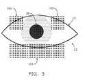
- FIG. 3is an example of a camera image of an eye and surrounding facial region in which three clusters of pixels are sampled to determine average illumination intensities in three regions within a camera's field-of-view.
- FIG. 4is an example of controlled illumination of grocery or warehouse shelves where a spatial gradient is desired in the illumination pattern. Illumination is separated into four (4) horizontal regions with progressively increasing brightness toward the right side of the image.
- FIG. 5is an example of the time sequence of feedback and signals used to control illumination using both amplitude modulation and pulse-width modulation techniques.
- FIG. 6is a flow chart showing an exemplary algorithm that may be used to control illumination levels of multiple light sources to generate spatially uniform brightness.
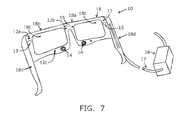
- FIG. 7is a perspective view of yet another embodiment of an apparatus for monitoring a person based upon movement of the person's eye.
- FIG. 1shows an exemplary embodiment of a system 10 that may provide feedback-controlled illumination of an eye and/or nearby facial regions of a person.
- the system 10includes a plurality of light sources 12 (three shown), one or more cameras 14 (one shown), and a processing unit 16 coupled to the light sources 12 and/or camera(s) 14 .
- the components of the system 10may be included on a single device or two or more separate devices.
- the camera 14 and light sources 12may be provided on a frame 18 or other device configured to be worn on a person's head.
- the frame 18includes a bridge piece 18 a , a rim 18 b extending above or around each eye and defining an opening 18 c , and/or a pair of ear supports 18 d , e.g., similar to a pair of eyeglasses.
- lensesmay or not be provided in the openings 18 c , e.g., prescription, shaded, polarized, and/or protective lenses, and the like, as desired, although such lenses are not necessary for operation of the system 10 .
- components of the system 10may be provided on other devices configured to be worn on a person's head, such as a helmet, a mask, a pair of goggles, a pull-down mask, and the like (not shown), such as those devices disclosed in U.S. Pat. No. 6,163,281, 6,542,081, or 7,488,294, the entire disclosures of which are expressly incorporated by reference herein.
- the componentsmay be provided on separate devices, e.g., stationary or moving structures, for monitoring a person, objects, and/or other scene, as described further elsewhere herein.
- the camera 14 and/or light sources 12may be provided remotely from a person yet allow the person to be monitored.
- the camera 14 and/or light sources 12may be mounted to a dashboard or elsewhere within the a cockpit or other interior region of a vehicle and oriented towards a driver, pilot, or other operator of the vehicle, a passenger, or other person within the vehicle.
- the positions of the camera 14 and/or light sources 12may be substantially fixed or adjustable within the vehicle, e.g., such that the camera 14 and/or light sources 12 may be oriented towards the face, e.g., one or both eyes of the operator or other person.
- the camera 14 and/or light sources 12may be mounted on or adjacent a display of a computer or other electronic device, for example, for monitoring one or both eyes of a user of the electronic device, e.g., to allow the user to control or operate the electronic device based at least in part on movement of one or both eyes.
- the processing unit 16may also be carried by the frame 18 or may be separate and/or remote from the frame 18 (and/or other components of the system 10 if provided on other structures than the frame 18 ), as described elsewhere herein.
- the processing unit 16may be provided in a casing separate from the frame 18 , and may include one or more cables 17 (one shown for simplicity) extending from the frame 18 .
- the cable(s) 17may include individual cables or sets of wires coupled to the light sources 12 , cameras 14 , and/or other components on the frame 18 and to the processing unit 16 .
- individual cables or sets of wiresmay be embedded in the frame 18 , e.g., along the rim 18 b , from respective light sources 12 , cameras 14 , 15 , and the like, until captured within the cable 15 , e.g., to reduce the overall profile of the frame 18 , as desired.
- a camera 14is mounted and/or positioned on the frame 18 such that the camera 14 includes a field-of-view that is directed towards a first eye 20 of a person wearing the frame 18 and/or otherwise being monitored with the system 10 , as shown.
- the camera 14may be offset from a respective opening 18 c in the frame 18 , e.g., to place the camera 14 away from the general viewing field of a person wearing the frame 18 , e.g., as described in co-pending application Ser. No. 12/551,547, filed Jan. 13, 2010, the entire disclosure of which is expressly incorporated by reference herein.
- the camera 14may include a CCD or CMOS or other detector including an active area, e.g., including a rectangular or other array of pixels, for capturing images with the camera 14 and generating video signals representing the images.
- the active area of the camera 14may have any desired shape, e.g., a square or rectangular shape, a circular or elliptical shape, and the like.
- the active area of the camera 14may be substantially flat or may be curved, e.g., to lie within a curved plane that may be oriented towards the eye 22 .
- Exemplary CMOS devices that may be usedinclude Omnivision, Model No. OV7740, or Mocron Model No. MT9V032.
- the camera 14may include one or more filters, lenses, and the like (not shown), if desired, e.g., to focus images on the active area, filter undesired intensities and/or wavelengths of light, and the like.
- a second cameramay be provided that includes a field-of-view directed towards a second eye (not shown) of a person being monitored by the system 10 .
- a pair of cameras 14may be mounted on the frame 18 , e.g., on a lower region of the rim 18 b below each eye to minimize interference with the person's vision, thereby allowing both eyes of the person to be monitored.
- multiple camerasmay be provided that are directed towards an individual eye of the person (or multiple cameras that are directed towards each eye, not shown), e.g., providing separate or overlapping fields-of-view.
- one or more cameras 15may be provided on the frame 18 that may be oriented away from the person wearing the frame 18 , e.g., to acquire images of the person's surroundings, as disclosed in the patents incorporated by reference elsewhere herein.
- the light sources 12may be mounted on the frame 18 at several locations, e.g., around the opening 18 c adjacent the camera 14 .
- three light sources 12 a , 12 b , 12 care shown, e.g., first and second light sources 12 a , 12 b on an upper region of the rim 18 b and a third light source 12 c on a lower region of the rim 18 b .
- only two or more than three light sourcesmay be provided, if desired, and may be controlled using the systems and methods described herein. If the system 10 includes a second camera 14 , as shown in FIG.
- an additional set of light sources 12may be provided on the frame 18 for illuminating a second eye and/or facial region (not shown) of a person wearing the frame 18 .
- the system 10includes multiple cameras directed towards an individual eye (not shown), the cameras may share a plurality of light sources or, alternatively, multiple sets of light sources may be provided for illuminating the respective fields-of-views of the cameras (also not shown).
- each light source 12may include a light emitting diode configured for emitting a relatively narrow or wide bandwidth of the light, e.g., infrared light at one or more wavelengths between about 640-700 nanometers, broadband visible light, e.g., white light, and the like.
- the light sources 12may include lenses, filters, diffusers, or other features (not shown), e.g., for facilitating lighting respective focal regions of the person's eye and/or face.
- the light sources 12may be spaced apart from one another, e.g., in one or more arrays located around respective openings 18 c in the frame 18 to provide desired brightness levels, e.g., substantially uniform or variable level brightness of the person's eye and/or face and thereby of images of the person's eye and/or face captured using the camera 14 .
- the processing unit 16may include one or more controllers or processors, e.g., one or more hardware components and/or software modules for operating various components of the system 10 .
- the processing unit 16may include a separate or integral controller (not shown) for controlling the light sources 12 and/or camera 14 , for receiving and/or processing signals from the camera 14 , and the like.
- one or more of the components of the processing unit 16may be carried on the frame 18 , e.g., on the ear supports 18 d or rim 18 b , similar to the embodiments described in the references incorporated by reference elsewhere herein.
- the processing unit 16may also include memory for storing image signals from the camera(s) 14 , 15 , filters for editing and/or processing the image signals, and the like.
- the processing unit 16may include one or more power sources (not shown), e.g., for operating the components of the system 10 .
- the frame 18 and/or processing unit 16may include one or more transmitters and/or receivers (not shown) for transmitting data, receiving instructions, and the like.
- the system 10may include components that are remote from the frame 18 and/or processing unit 16 , similar to embodiments disclosed in the references incorporated by reference elsewhere herein.
- the system 10may include one or more receivers, processors, and/or displays (not shown) at a remote location from the processing unit 16 and/or frame 18 , e.g., in the same room, at a nearby monitoring station, or at a more distant location.
- an eye 20 and surrounding facial region 22are shown of a person being imaged using the system 10 , e.g., for the purpose of automated pupil-tracking, in which substantially spatially uniform illumination may be useful.
- the facial region 22 including the eye 20may be visualized by the camera 14 where images are communicated to the processing unit 16 .
- the pupil 26is located in the center of the iris 27 .
- the iris 27is located within the sclera 28 or white region of the eye. During normal vision, the location of the pupil 26 varies as a result of both voluntary and involuntary muscular control.
- the size and shape of the pupil 26 , iris 27 , and areas associated with the sclera 28change within the field-of-view of the camera. In part, changes in size and shape may be due to the curvature of the eye 20 .
- a number of factorscan influence the intensity of light detected from different regions within the field-of-view of a camera: a) the distances between light sources and the field-of-view region, b) the intensity of each light source, c) the divergence angle of each light source, d) the reflectivity (at illumination wavelength(s)) of the illuminated surface, e) the curvature of the surface, and f) the efficiency of the camera in converting light into useful signals as well as the collection efficiency and spatial uniformity of the optics associated with the camera.
- three-dimensional structurescan generate shadows if illuminated from a single or small number of light sources. In the case of the region 22 around the eye 20 , shadows can be generated by structures that include eyelids, eye lashes, and skin folds.
- the brightness levels of different regions within the field-Of-view of a cameramay be used, in a feedback mode, to control the intensity of different illumination sources.
- the use of multiple light sources illuminating a scene from different anglesmay help to reduce the detrimental effects of shadows. Glints may also be reduced or avoided by using multiple illumination sources and/or by placing them at strategic locations, e.g., well away from the viewing angle of the camera.
- LEDsinfrared light emitting diodes
- FIG. 2shows respective focal regions of illumination by different light sources.
- three light sourcesilluminate a pupil 26 and the facial region 22 around an eye 20 .
- the dashes linesrepresent “focal regions,” i.e., regions where specific light sources have a preferential or increased influence on illumination of a region compared to surrounding areas within the camera's field-of-view.
- LED 12 apreferentially illuminates area 121 of FIG. 2 located in the upper-left region of the camera's field-of-view.
- LED 12 b in FIG. 1illuminates area 122 of FIG.
- LED 12 c in FIG. 1illuminates area 123 of FIG. 2 located in the lower region of the camera's field-of-view.
- the size of the illuminated areas or focal regionsmay be dependent on the divergence angle of the light source and/or the distance between the light source and the illuminated surface.
- the general shape of the illuminated areamay be dependent on the light profile of the light source as well as the angle between the location of the light source and a vector normal to the illuminated surface.
- the average brightness of each focal regionmay be controlled by adjusting the intensity of the associated light source(s).
- FIG. 3is an example of pixel clusters that may be sampled to determine the average brightness of regions in the vicinity of a pupil 26 .
- the average measured intensity of an eight by eight (8 ⁇ 8) element cluster of pixels 101is used to assess the brightness of the upper-left region within a camera's field-of-view.
- Another eight by eight (8 ⁇ 8) element cluster of pixels 102is used to compute the brightness of the upper-right region within a camera's field-of-view.
- a third eight by thirty two (8 ⁇ 32) element cluster of pixels 103is used to assess the brightness of the lower region within the camera's field-of-view.
- brightnessmay be assessed from any number of regions with a field-of-view.
- the assessment of brightnessmay be determined from any number of pixels in clusters of any size, spacing or shape within each focal region. For example, the same pixels may be sampled during each sampling within each focal region, or different pixels, e.g., randomly selected within each focal region, may be sampled, if desired.
- Brightnessmay be sampled using actual video signals during monitoring the eye 20 or may be sampled outside the data stream using for monitoring the eye 20 . For example, periodic frames from a series of video signals may be sampled in addition to being recorded, processed, or otherwise monitored, to estimate and/or modulate brightness levels using any of the systems and methods described herein.
- the processing unit 16may sample predetermined pixels 101 , 102 , 103 (shown in FIG. 3 ) in focal regions 121 , 122 , 123 (shown in FIG. 2 ) periodically to estimate the average brightness level in each of the focal regions 121 , 122 , 123 .
- the processing unit 16may then modulate the light sources 12 a , 12 b , 12 c (shown in FIG. 1 ) to provide desired brightness levels within the respective focal regions 121 , 122 , 123 . For example, it may be desirable to have substantially uniform brightness when illuminating and imaging the eye 20 with the camera 14 .
- the processing unit 16may sample the sets of pixels 101 , 102 , 103 , determine the average brightness in each of the focal regions 121 , 122 , 123 , and increase or decrease the intensity of the light sources 12 a , 12 b , 12 c , e.g., to maintain the average brightness substantially uniform and/or otherwise within desired ranges.
- one or more of the camerasmay be used to sample brightness within the field-of-view of the camera(s).
- a first cameramay be used exclusively for brightness sampling, e.g., as described above, while a second camera may be used to obtain images of the eye for other purposes, e.g., monitoring the person's awareness, physical and/or mental state, controlling one or more devices, and the like, as described elsewhere herein and in the references incorporated by reference herein.
- multiple camerasmay be used to sample brightness within focal regions of respective light sources and the sampled brightness from the multiple cameras may be averaged or otherwise compared to provide feedback control to the light sources.
- some objects and lettering on objectsmay appear to be smaller than others within images acquired using the camera 241 . This may be due to an actual reduced size of objects or because objects are further from the camera. Frequently, the performance of image processing algorithms may be improved by increasing the brightness (without generating saturation) of objects that appear smaller within the camera's field-of-view. Spatially controlled illumination may also be used to help image processing algorithms compensate for spatial variation in the resolution of lenses and other optical components by increasing the ratio of signal-to-noise. Most lenses, particularly small lenses, have a decreased spatial resolution and/or light-gathering capability nearer the outer edges of the lens compared to the central region of the lens.
- a horizontal gradient of brightnessmay be generated by dividing the field-of-view into 4 vertical regions.
- the left-most region 221illuminated by LED 231 , may require the least brightness for reliable image processing.
- the next left-most region 222 , illuminated by LED 232may require the next least level of brightness for reliable image processing.
- Region 223illuminated by LED 233 , may require more brightness due to the presence of smaller objects.
- region 224illuminated by LED 234 , may require the most illumination because of the presence of small objects, the objects being furthest from the camera, and/or a decreased optical resolution near the edge of the images acquired using the camera 241 .
- a processing unitmay be coupled to the camera 241 to sample brightness levels within the vertical regions 221 - 224 , and/or may be coupled to the light sources 231 - 234 to modulate the intensity of the light sources 231 - 234 in response to the sampled brightness levels. For example, as explained above, the processing unit may modulate the light sources 231 - 234 to provide increased brightness levels in each of the regions 221 - 224 to facilitate monitoring images from the camera 241 .
- FIG. 5is an example of a time sequence of signals used to monitor and control illumination in different regions of a camera's field-of-view.
- Trace 141may represent measured average brightness of an individual pixel cluster, while dashed line 140 may represent a target light intensity for a focal region of a light source.
- Dots 142may represent times at which new camera images are collected for sampling brightness. If the measured average light intensity falls below the target intensity, different schemes may be used to increase the intensity of the light source associated with the corresponding region. Conversely, if the measured average light intensity rises above the target intensity, the same scheme(s) may be used to decrease the brightness of the light source associated with the corresponding region.
- trace 143illustrates a scheme in which the amplitude of either the voltage or the current driving a light source may be used to control light intensity. This is generally referred to as “amplitude modulation.”
- trace 144illustrates a scheme is which the duration or “dwell time” of a controlling voltage or current may be modified to control light intensity. This is generally referred to as “pulse-width modulation.”
- pulse-width modulationit may also be possible to use both schemes simultaneously.
- illuminationmay be turned off at times when not needed such as when the camera is not converting light into useful signals or when the overall device is not in use, for example, to conserve energy and/or to reduce overall illumination intensities, e.g., for safety reasons.
- the light sources 231 - 234 in FIG. 4may be operated intermittently, e.g., deactivated when the camera 241 is inoperative.
- the camera 241may be operated periodically to acquire images of its field-of-view as well as sample brightness, e.g., from the acquired images.
- the light sources 231 - 234may be activated only during the periods when the camera 241 is acquiring images with the brightness of the light sources controlled as described elsewhere herein, e.g., using amplitude modulation and/or pulse-width modulation during the periods of activation.
- the camera 241may be operated periodically to acquire images of the field-of-view and separately to sample brightness.
- the light sources 231 - 234may be activated intermittently only during the periods when the camera 241 is activated to acquire images and/or to sample brightness, e.g., using amplitude modulation and/or pulse-width modulation during the periods of activation.
- FIG. 6is a flowchart of an exemplary algorithm that may be used to generate feedback control, e.g., to produce controlled or uniform illumination, such as using the system 10 of FIGS. 1 and 7 or the system of FIG. 4 .
- the average brightness of each region(indexed as “n”) may be measured successively within video images. For example, at step 310 , a new image may be collected from a camera illuminated by a plurality of light sources.
- the average brightness of a first focal region corresponding to a first light sourcemay be sampled by sampling a plurality of pixels from the new image within the first region. For example, the actual brightness levels of the plurality of pixels within the first region may be obtained and averaged to determine an average brightness for the first region.
- the average brightnessmay be compared with a target intensity for the first region. If the average brightness is greater than the target intensity (branch 330 a ), at step 332 , the output to the first light source is decreased. If the average brightness is less than the target intensity (branch 330 b ), at step 334 , the output to the first light source is increased. Thus, at step 336 , the first light source is modulated to the desired intensity.
- the number “n”is increased and, at step 340 , it is confirmed that another focal region exists that has not yet been sampled. If “n” is less than or equal to the total number of focal regions and light sources, the process is repeated, i.e., steps 320 - 336 for the second focal region and light source, etc. if all of the focal regions have been sampled from the new image and the light sources modulated, the process is repeated with a new image (starting again at step 310 ). Thus, with each sampling, the output to the entire array of light sources included in the system may be modulated to desired levels. The process may then be repeated upon collection of the next video image or only periodically, e.g., after every other or every tenth image acquired using the camera providing the sampled brightness.
- Target brightness levelsmay be the same for all regions throughout a camera's field-of-view to generate a scene with substantially uniform brightness, e.g., in the system 10 of FIGS. 1 and 7 .
- target brightness levelsmay also be selected to vary in different spatial regions within a camera's field-of-view, such as the system depicted in FIG. 4 , to partially compensate for the effects of reduced object size within images.
- target brightness within one or more regionsmay also be elevated to produce spatial gradient patterns, e.g., to enhance analysis, for example, in order to reveal detailed cracks in a surface or subtle changes in color.
- Target brightness levelsmay also be selected to vary as a function of time. If sets of illumination sources are used that emit at different wavelengths, separate target brightness levels may be desired as each wavelength is selected to reveal different structures within camera images.
- brightnessmay be dominated by the electromagnetic sources that are a part of the applied illumination system.
- light from the feedback-controlled illumination systemmay be superimposed on ambient light sources such as the sun or room lighting. In the latter case, it may be necessary to re-converge to desired brightness levels whenever ambient lighting levels change.
- Another example of an application where feedback-controlled dynamic lighting may be utilizedincludes security checkpoints where vehicles or individuals are identified as they approach a camera's field-of-view.
- either visible or infrared illumination sourcesmay be dynamically modulated to avoid shadows and/or illuminate objects for uniform scene brightness while avoiding hot-spots within images.
- Another example of an application where feedback-controlled dynamic lighting may be utilizedis in sorting processes within assembly lines or conveyor belt systems such as those used to sort produce or other foodstuffs, such as apples or fish (not shown).
- lightingmay be adjusted dynamically to better measure the dimensions and/or identify objects.
- the camera (or multiple cameras, as described elsewhere herein) and plurality of light sourcesmay be mounted to stationary supports adjacent an assembly line or conveyor belt and directed towards objects on carried on the assembly line or conveyor belt (not shown).
- multiple stationary camerasmay be provided and multiple sets of light sources may be provided, e.g., that are stationary relative to respective cameras or that are mounted to an assembly line or conveyor belt such that light sources move with objects on the assembly line or conveyor belt.
- Another example of an application where feedback-controlled dynamic lighting may be utilizedincludes alignment systems such as those used to precisely align wheels and drive shafts. Another example of an application where feedback-controlled dynamic lighting may be utilized is in the field of face recognition.
Landscapes
- Engineering & Computer Science (AREA)
- Multimedia (AREA)
- Signal Processing (AREA)
- Physics & Mathematics (AREA)
- Health & Medical Sciences (AREA)
- Acoustics & Sound (AREA)
- General Health & Medical Sciences (AREA)
- Otolaryngology (AREA)
- General Physics & Mathematics (AREA)
- Ophthalmology & Optometry (AREA)
- Optics & Photonics (AREA)
- Image Processing (AREA)
- Studio Devices (AREA)
- Circuit Arrangement For Electric Light Sources In General (AREA)
- Image Analysis (AREA)
- Exposure Control For Cameras (AREA)
Abstract
Description
Claims (52)
Priority Applications (9)
| Application Number | Priority Date | Filing Date | Title |
|---|---|---|---|
| US12/715,177US8890946B2 (en) | 2010-03-01 | 2010-03-01 | Systems and methods for spatially controlled scene illumination |
| AU2011258826AAU2011258826A1 (en) | 2010-03-01 | 2011-03-01 | Systems and methods for spatially controlled scene illumination |
| RU2012141574/07ARU2012141574A (en) | 2010-03-01 | 2011-03-01 | SYSTEMS AND METHODS FOR A SPACE-CONTROLLED SCENE LIGHTING |
| PCT/US2011/026736WO2011149577A2 (en) | 2010-03-01 | 2011-03-01 | Systems and methods for spatially controlled scene illumination |
| EP11787052.7AEP2543187B1 (en) | 2010-03-01 | 2011-03-01 | Systems and methods for spatially controlled scene illumination |
| KR1020127025691AKR101829850B1 (en) | 2010-03-01 | 2011-03-01 | Systems and methods for spatially controlled scene illumination |
| JP2012556180AJP2013521710A (en) | 2010-03-01 | 2011-03-01 | System and method for spatially adjusted scene lighting |
| CN201180022056.1ACN102918834B (en) | 2010-03-01 | 2011-03-01 | Systems and methods for spatially controlled scene lighting |
| US14/546,821US20150181100A1 (en) | 2010-03-01 | 2014-11-18 | Systems and methods for spatially controlled scene illumination |
Applications Claiming Priority (1)
| Application Number | Priority Date | Filing Date | Title |
|---|---|---|---|
| US12/715,177US8890946B2 (en) | 2010-03-01 | 2010-03-01 | Systems and methods for spatially controlled scene illumination |
Related Child Applications (1)
| Application Number | Title | Priority Date | Filing Date |
|---|---|---|---|
| US14/546,821ContinuationUS20150181100A1 (en) | 2010-03-01 | 2014-11-18 | Systems and methods for spatially controlled scene illumination |
Publications (2)
| Publication Number | Publication Date |
|---|---|
| US20110211056A1 US20110211056A1 (en) | 2011-09-01 |
| US8890946B2true US8890946B2 (en) | 2014-11-18 |
Family
ID=44505076
Family Applications (2)
| Application Number | Title | Priority Date | Filing Date |
|---|---|---|---|
| US12/715,177Active2032-06-03US8890946B2 (en) | 2010-03-01 | 2010-03-01 | Systems and methods for spatially controlled scene illumination |
| US14/546,821AbandonedUS20150181100A1 (en) | 2010-03-01 | 2014-11-18 | Systems and methods for spatially controlled scene illumination |
Family Applications After (1)
| Application Number | Title | Priority Date | Filing Date |
|---|---|---|---|
| US14/546,821AbandonedUS20150181100A1 (en) | 2010-03-01 | 2014-11-18 | Systems and methods for spatially controlled scene illumination |
Country Status (8)
| Country | Link |
|---|---|
| US (2) | US8890946B2 (en) |
| EP (1) | EP2543187B1 (en) |
| JP (1) | JP2013521710A (en) |
| KR (1) | KR101829850B1 (en) |
| CN (1) | CN102918834B (en) |
| AU (1) | AU2011258826A1 (en) |
| RU (1) | RU2012141574A (en) |
| WO (1) | WO2011149577A2 (en) |
Cited By (16)
| Publication number | Priority date | Publication date | Assignee | Title |
|---|---|---|---|---|
| US20170090557A1 (en)* | 2014-01-29 | 2017-03-30 | Google Inc. | Systems and Devices for Implementing a Side-Mounted Optical Sensor |
| US20170219340A1 (en)* | 2016-01-28 | 2017-08-03 | Manatec Electronics Pvt.Ltd. | System for simultaneous measurement of wheel alignment angles and wheel runout of multi-axle vehicles |
| US9736373B2 (en)* | 2013-10-25 | 2017-08-15 | Intel Corporation | Dynamic optimization of light source power |
| US20180103839A1 (en)* | 2016-10-13 | 2018-04-19 | Ronald Michael Kurtz | Networked system of mobile communication platforms for nonpharmacologic constriction of a pupil |
| CN108507636A (en)* | 2017-02-27 | 2018-09-07 | 深圳市朗驰欣创科技股份有限公司 | A kind of detection method of channel stagnant water situation, inspection device and water level detecting equipment |
| US20180324343A1 (en)* | 2015-11-10 | 2018-11-08 | Lumileds Holding B.V. | Adaptive light source |
| US10295827B1 (en)* | 2017-04-27 | 2019-05-21 | Facebook Technologies, Llc | Diffractive optics beam shaping for structured light generator |
| US20190266964A1 (en)* | 2016-09-08 | 2019-08-29 | Boe Technology Group Co., Ltd. | Method and circuit for modulating eye diagram amplitude, method and circuitry for data transmission, and display device |
| US10506681B1 (en) | 2018-08-09 | 2019-12-10 | Distech Controls Inc. | Environment controller and method for proportionally adjusting the light intensity of several lighting devices |
| US20200201430A1 (en)* | 2018-06-01 | 2020-06-25 | Facebook Technologies, Llc | Determining fixation of a user's eyes from images of portions of the user's face enclosed by a head mounted display |
| US20210289176A1 (en)* | 2018-11-07 | 2021-09-16 | Sony Group Corporation | Image acquisition system and image acquisition method |
| US11592899B1 (en) | 2021-10-28 | 2023-02-28 | Tectus Corporation | Button activation within an eye-controlled user interface |
| US11619994B1 (en) | 2022-01-14 | 2023-04-04 | Tectus Corporation | Control of an electronic contact lens using pitch-based eye gestures |
| US11874961B2 (en) | 2022-05-09 | 2024-01-16 | Tectus Corporation | Managing display of an icon in an eye tracking augmented reality device |
| US12118138B2 (en) | 2022-02-14 | 2024-10-15 | Tectus Corporation | Vergence authentication |
| US12135471B2 (en) | 2021-09-10 | 2024-11-05 | Tectus Corporation | Control of an electronic contact lens using eye gestures |
Families Citing this family (147)
| Publication number | Priority date | Publication date | Assignee | Title |
|---|---|---|---|---|
| US9250703B2 (en) | 2006-03-06 | 2016-02-02 | Sony Computer Entertainment Inc. | Interface with gaze detection and voice input |
| US8730156B2 (en) | 2010-03-05 | 2014-05-20 | Sony Computer Entertainment America Llc | Maintaining multiple views on a shared stable virtual space |
| US9158116B1 (en) | 2014-04-25 | 2015-10-13 | Osterhout Group, Inc. | Temple and ear horn assembly for headworn computer |
| US9400390B2 (en) | 2014-01-24 | 2016-07-26 | Osterhout Group, Inc. | Peripheral lighting for head worn computing |
| US9715112B2 (en) | 2014-01-21 | 2017-07-25 | Osterhout Group, Inc. | Suppression of stray light in head worn computing |
| US9366867B2 (en) | 2014-07-08 | 2016-06-14 | Osterhout Group, Inc. | Optical systems for see-through displays |
| KR101383235B1 (en)* | 2010-06-17 | 2014-04-17 | 한국전자통신연구원 | Apparatus for inputting coordinate using eye tracking and method thereof |
| WO2012011181A1 (en)* | 2010-07-22 | 2012-01-26 | 富士通株式会社 | Vein image capturing device |
| US20130154913A1 (en)* | 2010-12-16 | 2013-06-20 | Siemens Corporation | Systems and methods for a gaze and gesture interface |
| US10120438B2 (en)* | 2011-05-25 | 2018-11-06 | Sony Interactive Entertainment Inc. | Eye gaze to alter device behavior |
| CN106484115B (en) | 2011-10-28 | 2019-04-19 | 奇跃公司 | Systems and methods for augmented and virtual reality |
| TWI471808B (en)* | 2012-07-20 | 2015-02-01 | Pixart Imaging Inc | Pupil detection device |
| US9854159B2 (en)* | 2012-07-20 | 2017-12-26 | Pixart Imaging Inc. | Image system with eye protection |
| TW201416908A (en) | 2012-10-23 | 2014-05-01 | Pixart Imaging Inc | Pupil tracking device |
| CN103793045B (en)* | 2012-10-31 | 2016-12-28 | 原相科技股份有限公司 | pupil tracking device |
| KR102205374B1 (en) | 2012-12-06 | 2021-01-21 | 아이플루언스, 인크. | Eye tracking wearable devices and methods for use |
| US8761594B1 (en) | 2013-02-28 | 2014-06-24 | Apple Inc. | Spatially dynamic illumination for camera systems |
| US9788906B2 (en) | 2013-03-15 | 2017-10-17 | Synaptive Medical (Barbados) Inc. | Context aware surgical systems for intraoperatively configuring imaging devices |
| US10063782B2 (en)* | 2013-06-18 | 2018-08-28 | Motorola Solutions, Inc. | Method and apparatus for displaying an image from a camera |
| US10686972B2 (en) | 2013-09-03 | 2020-06-16 | Tobii Ab | Gaze assisted field of view control |
| CN113576398A (en) | 2013-09-03 | 2021-11-02 | 托比股份公司 | Portable eye tracking device |
| US10310597B2 (en) | 2013-09-03 | 2019-06-04 | Tobii Ab | Portable eye tracking device |
| TWI532413B (en)* | 2013-09-11 | 2016-05-01 | 晶睿通訊股份有限公司 | Lighting fill light system and method |
| US10649220B2 (en) | 2014-06-09 | 2020-05-12 | Mentor Acquisition One, Llc | Content presentation in head worn computing |
| US9594246B2 (en) | 2014-01-21 | 2017-03-14 | Osterhout Group, Inc. | See-through computer display systems |
| US9829707B2 (en) | 2014-08-12 | 2017-11-28 | Osterhout Group, Inc. | Measuring content brightness in head worn computing |
| US11103122B2 (en) | 2014-07-15 | 2021-08-31 | Mentor Acquisition One, Llc | Content presentation in head worn computing |
| US9810906B2 (en) | 2014-06-17 | 2017-11-07 | Osterhout Group, Inc. | External user interface for head worn computing |
| US20150228119A1 (en) | 2014-02-11 | 2015-08-13 | Osterhout Group, Inc. | Spatial location presentation in head worn computing |
| US10254856B2 (en) | 2014-01-17 | 2019-04-09 | Osterhout Group, Inc. | External user interface for head worn computing |
| US9841599B2 (en) | 2014-06-05 | 2017-12-12 | Osterhout Group, Inc. | Optical configurations for head-worn see-through displays |
| US10684687B2 (en) | 2014-12-03 | 2020-06-16 | Mentor Acquisition One, Llc | See-through computer display systems |
| US12105281B2 (en) | 2014-01-21 | 2024-10-01 | Mentor Acquisition One, Llc | See-through computer display systems |
| US11892644B2 (en) | 2014-01-21 | 2024-02-06 | Mentor Acquisition One, Llc | See-through computer display systems |
| US11487110B2 (en) | 2014-01-21 | 2022-11-01 | Mentor Acquisition One, Llc | Eye imaging in head worn computing |
| US12093453B2 (en) | 2014-01-21 | 2024-09-17 | Mentor Acquisition One, Llc | Eye glint imaging in see-through computer display systems |
| US11737666B2 (en) | 2014-01-21 | 2023-08-29 | Mentor Acquisition One, Llc | Eye imaging in head worn computing |
| US9753288B2 (en) | 2014-01-21 | 2017-09-05 | Osterhout Group, Inc. | See-through computer display systems |
| US11669163B2 (en) | 2014-01-21 | 2023-06-06 | Mentor Acquisition One, Llc | Eye glint imaging in see-through computer display systems |
| US9846308B2 (en) | 2014-01-24 | 2017-12-19 | Osterhout Group, Inc. | Haptic systems for head-worn computers |
| US20160018651A1 (en) | 2014-01-24 | 2016-01-21 | Osterhout Group, Inc. | See-through computer display systems |
| US9396571B2 (en)* | 2014-02-10 | 2016-07-19 | International Business Machines Corporation | Simplified lighting compositing |
| US12112089B2 (en) | 2014-02-11 | 2024-10-08 | Mentor Acquisition One, Llc | Spatial location presentation in head worn computing |
| US20160187651A1 (en) | 2014-03-28 | 2016-06-30 | Osterhout Group, Inc. | Safety for a vehicle operator with an hmd |
| US10853589B2 (en) | 2014-04-25 | 2020-12-01 | Mentor Acquisition One, Llc | Language translation with head-worn computing |
| US9651787B2 (en) | 2014-04-25 | 2017-05-16 | Osterhout Group, Inc. | Speaker assembly for headworn computer |
| US20160137312A1 (en) | 2014-05-06 | 2016-05-19 | Osterhout Group, Inc. | Unmanned aerial vehicle launch system |
| WO2016018487A2 (en) | 2014-05-09 | 2016-02-04 | Eyefluene, Inc. | Systems and methods for biomechanically-based eye signals for interacting with real and virtual objects |
| US10564714B2 (en) | 2014-05-09 | 2020-02-18 | Google Llc | Systems and methods for biomechanically-based eye signals for interacting with real and virtual objects |
| US10663740B2 (en) | 2014-06-09 | 2020-05-26 | Mentor Acquisition One, Llc | Content presentation in head worn computing |
| JP2016032257A (en)* | 2014-07-30 | 2016-03-07 | 株式会社デンソー | Driver monitoring device |
| US9942966B2 (en)* | 2014-09-25 | 2018-04-10 | Philips Lighting Holding B.V. | Control of lighting |
| WO2016084385A1 (en)* | 2014-11-27 | 2016-06-02 | 京セラ株式会社 | Imaging device and vehicle |
| US9635231B2 (en) | 2014-12-22 | 2017-04-25 | Google Inc. | Time-of-flight camera system and method to improve measurement quality of weak field-of-view signal regions |
| US9674415B2 (en) | 2014-12-22 | 2017-06-06 | Google Inc. | Time-of-flight camera system with scanning illuminator |
| US10878775B2 (en) | 2015-02-17 | 2020-12-29 | Mentor Acquisition One, Llc | See-through computer display systems |
| WO2016156586A1 (en)* | 2015-04-02 | 2016-10-06 | Essilor International (Compagnie Generale D'optique) | A method for updating an index of a person |
| WO2016162554A1 (en)* | 2015-04-10 | 2016-10-13 | Essilor International (Compagnie Generale D'optique) | Head mounted display device |
| IL295437B2 (en) | 2015-05-19 | 2024-11-01 | Magic Leap Inc | Dual integrated light field device |
| EP3923229A1 (en) | 2015-06-24 | 2021-12-15 | Magic Leap, Inc. | Augmented reality devices, systems and methods for purchasing |
| US10139966B2 (en) | 2015-07-22 | 2018-11-27 | Osterhout Group, Inc. | External user interface for head worn computing |
| US11003246B2 (en) | 2015-07-22 | 2021-05-11 | Mentor Acquisition One, Llc | External user interface for head worn computing |
| WO2017054004A1 (en) | 2015-09-24 | 2017-03-30 | California Instutute Of Technology | Systems and methods for data visualization using tree-dimensional displays |
| CN106814518A (en)* | 2015-12-01 | 2017-06-09 | 深圳富泰宏精密工业有限公司 | Auto-focusing camera system and electronic installation |
| US10850116B2 (en) | 2016-12-30 | 2020-12-01 | Mentor Acquisition One, Llc | Head-worn therapy device |
| US10591728B2 (en) | 2016-03-02 | 2020-03-17 | Mentor Acquisition One, Llc | Optical systems for head-worn computers |
| US10667981B2 (en) | 2016-02-29 | 2020-06-02 | Mentor Acquisition One, Llc | Reading assistance system for visually impaired |
| US9826299B1 (en) | 2016-08-22 | 2017-11-21 | Osterhout Group, Inc. | Speaker systems for head-worn computer systems |
| US9880441B1 (en) | 2016-09-08 | 2018-01-30 | Osterhout Group, Inc. | Electrochromic systems for head-worn computer systems |
| US9910284B1 (en) | 2016-09-08 | 2018-03-06 | Osterhout Group, Inc. | Optical systems for head-worn computers |
| US10684478B2 (en) | 2016-05-09 | 2020-06-16 | Mentor Acquisition One, Llc | User interface systems for head-worn computers |
| US10466491B2 (en) | 2016-06-01 | 2019-11-05 | Mentor Acquisition One, Llc | Modular systems for head-worn computers |
| US10084979B2 (en)* | 2016-07-29 | 2018-09-25 | International Business Machines Corporation | Camera apparatus and system, method and recording medium for indicating camera field of view |
| KR102548199B1 (en)* | 2016-08-03 | 2023-06-28 | 삼성전자주식회사 | Electronic device and method for tracking gaze in the electronic device |
| US10580234B2 (en) | 2017-01-20 | 2020-03-03 | Adesa, Inc. | Vehicle documentation system |
| US10302764B2 (en)* | 2017-02-03 | 2019-05-28 | Microsoft Technology Licensing, Llc | Active illumination management through contextual information |
| AU2018243565B2 (en) | 2017-03-30 | 2023-03-16 | Magic Leap, Inc. | Non-blocking dual driver earphones |
| US10977858B2 (en) | 2017-03-30 | 2021-04-13 | Magic Leap, Inc. | Centralized rendering |
| IL269861B2 (en) | 2017-04-14 | 2023-11-01 | Magic Leap Inc | Multimodal eye tracking |
| US11079522B1 (en) | 2017-05-31 | 2021-08-03 | Magic Leap, Inc. | Fiducial design |
| US10422995B2 (en) | 2017-07-24 | 2019-09-24 | Mentor Acquisition One, Llc | See-through computer display systems with stray light management |
| US10578869B2 (en) | 2017-07-24 | 2020-03-03 | Mentor Acquisition One, Llc | See-through computer display systems with adjustable zoom cameras |
| US11409105B2 (en) | 2017-07-24 | 2022-08-09 | Mentor Acquisition One, Llc | See-through computer display systems |
| CN110892443B (en)* | 2017-08-01 | 2024-01-09 | 松下知识产权经营株式会社 | Personal authentication device |
| US10969584B2 (en) | 2017-08-04 | 2021-04-06 | Mentor Acquisition One, Llc | Image expansion optic for head-worn computer |
| IL307592A (en) | 2017-10-17 | 2023-12-01 | Magic Leap Inc | Spatial audio for mixed reality |
| US11393251B2 (en) | 2018-02-09 | 2022-07-19 | Pupil Labs Gmbh | Devices, systems and methods for predicting gaze-related parameters |
| WO2019154511A1 (en) | 2018-02-09 | 2019-08-15 | Pupil Labs Gmbh | Devices, systems and methods for predicting gaze-related parameters using a neural network |
| EP3750028B1 (en) | 2018-02-09 | 2022-10-19 | Pupil Labs GmbH | Devices, systems and methods for predicting gaze-related parameters |
| IL305799B2 (en) | 2018-02-15 | 2024-10-01 | Magic Leap Inc | Virtual reverberation in mixed reality |
| CN111713090B (en) | 2018-02-15 | 2023-02-17 | 奇跃公司 | Mixed reality musical instrument |
| WO2019161314A1 (en) | 2018-02-15 | 2019-08-22 | Magic Leap, Inc. | Dual listener positions for mixed reality |
| CN112119340B (en)* | 2018-04-18 | 2022-07-12 | 金泰克斯公司 | Illumination of limited field of view in surgical microscopes |
| WO2019200434A1 (en)* | 2018-04-19 | 2019-10-24 | Seeing Machines Limited | Infrared light source protective system |
| CN112602005A (en) | 2018-04-24 | 2021-04-02 | 曼特收购第一有限责任公司 | See-through computer display system with vision correction and increased content density |
| WO2019221767A1 (en) | 2018-05-14 | 2019-11-21 | Virtualitics, Inc. | Systems and methods for high dimensional 3d data visualization |
| US10779082B2 (en) | 2018-05-30 | 2020-09-15 | Magic Leap, Inc. | Index scheming for filter parameters |
| US10667072B2 (en) | 2018-06-12 | 2020-05-26 | Magic Leap, Inc. | Efficient rendering of virtual soundfields |
| WO2019241760A1 (en) | 2018-06-14 | 2019-12-19 | Magic Leap, Inc. | Methods and systems for audio signal filtering |
| JP7478100B2 (en) | 2018-06-14 | 2024-05-02 | マジック リープ, インコーポレイテッド | Reverberation Gain Normalization |
| WO2019246164A1 (en) | 2018-06-18 | 2019-12-26 | Magic Leap, Inc. | Spatial audio for interactive audio environments |
| WO2019246562A1 (en) | 2018-06-21 | 2019-12-26 | Magic Leap, Inc. | Wearable system speech processing |
| JP7499749B2 (en) | 2018-07-24 | 2024-06-14 | マジック リープ, インコーポレイテッド | Application Sharing |
| JP7316360B2 (en) | 2018-09-25 | 2023-07-27 | マジック リープ, インコーポレイテッド | Systems and methods for augmented reality |
| EP3861763A4 (en) | 2018-10-05 | 2021-12-01 | Magic Leap, Inc. | Highlighting audio spatialization |
| CN113170272B (en) | 2018-10-05 | 2023-04-04 | 奇跃公司 | Near-field audio rendering |
| US11315325B2 (en) | 2018-10-09 | 2022-04-26 | Magic Leap, Inc. | Systems and methods for artificial intelligence-based virtual and augmented reality |
| CN113227935B (en) | 2018-10-24 | 2024-09-13 | 奇跃公司 | Asynchronous ASIC |
| CN111127537A (en)* | 2018-10-29 | 2020-05-08 | 托比股份公司 | Method and apparatus for detecting shadows in a head mounted device |
| KR102549130B1 (en)* | 2018-11-26 | 2023-07-03 | 제트카베 그룹 게엠베하 | Vehicle vision systems with adaptive reversing lights |
| WO2020140078A1 (en) | 2018-12-27 | 2020-07-02 | Magic Leap, Inc. | Systems and methods for virtual and augmented reality |
| US11537202B2 (en) | 2019-01-16 | 2022-12-27 | Pupil Labs Gmbh | Methods for generating calibration data for head-wearable devices and eye tracking system |
| US11587563B2 (en) | 2019-03-01 | 2023-02-21 | Magic Leap, Inc. | Determining input for speech processing engine |
| US12245097B2 (en) | 2019-03-25 | 2025-03-04 | Magic Leap, Inc. | Systems and methods for virtual and augmented reality |
| EP4510125A1 (en) | 2019-04-19 | 2025-02-19 | Magic Leap, Inc. | Identifying input for speech recognition engine |
| EP3979896B1 (en) | 2019-06-05 | 2024-11-13 | Pupil Labs GmbH | Devices, systems and methods for predicting gaze-related parameters |
| JP7369212B2 (en) | 2019-06-06 | 2023-10-25 | マジック リープ, インコーポレイテッド | Photorealistic character construction for spatial computing |
| WO2020251792A1 (en) | 2019-06-11 | 2020-12-17 | Gentex Corporation | Wearable medical device |
| WO2020253949A1 (en) | 2019-06-18 | 2020-12-24 | Pupil Labs Gmbh | Systems and methods for determining one or more parameters of a user's eye |
| US11704874B2 (en) | 2019-08-07 | 2023-07-18 | Magic Leap, Inc. | Spatial instructions and guides in mixed reality |
| US11328740B2 (en) | 2019-08-07 | 2022-05-10 | Magic Leap, Inc. | Voice onset detection |
| CN110490017B (en)* | 2019-08-08 | 2022-02-22 | 广东斯玛特自动化科技有限公司 | Illumination method and device for code scanner |
| WO2021077024A1 (en) | 2019-10-18 | 2021-04-22 | Magic Leap, Inc. | Gravity estimation and bundle adjustment for visual-inertial odometry |
| CN114586382B (en) | 2019-10-25 | 2025-09-23 | 奇跃公司 | A method, system and medium for determining and processing audio information |
| US11488365B2 (en) | 2019-10-25 | 2022-11-01 | Magic Leap, Inc. | Non-uniform stereo rendering |
| US11959997B2 (en) | 2019-11-22 | 2024-04-16 | Magic Leap, Inc. | System and method for tracking a wearable device |
| CN115698847A (en) | 2019-12-04 | 2023-02-03 | 奇跃公司 | Variable pitch color emissive display |
| WO2021113781A1 (en) | 2019-12-06 | 2021-06-10 | Magic Leap, Inc. | Environment acoustics persistence |
| JP7676400B2 (en) | 2019-12-09 | 2025-05-14 | マジック リープ, インコーポレイテッド | SYSTEM AND METHOD FOR OPERATING A HEAD MOUNTED DISPLAY SYSTEM BASED ON USER IDENTIFICATION - Patent application |
| US11337023B2 (en) | 2019-12-20 | 2022-05-17 | Magic Leap, Inc. | Physics-based audio and haptic synthesis |
| WO2021163224A1 (en) | 2020-02-10 | 2021-08-19 | Magic Leap, Inc. | Dynamic colocation of virtual content |
| CN115398316B (en) | 2020-02-14 | 2025-08-26 | 奇跃公司 | 3D object annotation |
| CN115698818B (en) | 2020-02-14 | 2024-01-23 | 奇跃公司 | Session manager |
| EP4104456A4 (en) | 2020-02-14 | 2023-07-19 | Magic Leap, Inc. | Multi-application audio rendering |
| JP2023514573A (en) | 2020-02-14 | 2023-04-06 | マジック リープ, インコーポレイテッド | tool bridge |
| US11778410B2 (en) | 2020-02-14 | 2023-10-03 | Magic Leap, Inc. | Delayed audio following |
| EP3973346B1 (en) | 2020-02-19 | 2024-12-25 | Pupil Labs GmbH | Eye tracking module and head-wearable device |
| US11205069B1 (en)* | 2020-02-20 | 2021-12-21 | Facebook Technologies, Llc | Hybrid cornea and pupil tracking |
| CN116325808B (en) | 2020-03-02 | 2023-12-22 | 奇跃公司 | Immersive audio platform |
| US11917384B2 (en) | 2020-03-27 | 2024-02-27 | Magic Leap, Inc. | Method of waking a device using spoken voice commands |
| US11636843B2 (en) | 2020-05-29 | 2023-04-25 | Magic Leap, Inc. | Surface appropriate collisions |
| WO2021243103A1 (en) | 2020-05-29 | 2021-12-02 | Magic Leap, Inc. | Determining angular acceleration |
| WO2022072752A1 (en) | 2020-09-30 | 2022-04-07 | Magic Leap, Inc. | Voice user interface using non-linguistic input |
| US12306413B2 (en) | 2021-03-12 | 2025-05-20 | Magic Leap , Inc. | Athermalization concepts for polymer eyepieces used in augmented reality or mixed reality devices |
| EP4332798A4 (en) | 2021-06-18 | 2024-10-30 | Samsung Electronics Co., Ltd. | BIOMETRIC AUTHENTICITY AUTHENTICATION METHOD AND ELECTRONIC DEVICE |
| KR20220169207A (en)* | 2021-06-18 | 2022-12-27 | 삼성전자주식회사 | Electronic device and biometric liveness authentication method |
| US11645844B2 (en)* | 2021-10-05 | 2023-05-09 | RS1 Worklete, LLC | Computing devices programmed to detect slippery surfaces within enclosures and methods/systems of used thereof |
Citations (114)
| Publication number | Priority date | Publication date | Assignee | Title |
|---|---|---|---|---|
| US3689135A (en) | 1971-01-26 | 1972-09-05 | Laurence R Young | Method for monitoring movement of a subject{40 s eyes |
| US3798599A (en) | 1972-02-24 | 1974-03-19 | H Kafafian | Single input controller for a communication system |
| US3863243A (en) | 1972-01-19 | 1975-01-28 | Max Skolnick | Sleep inhibiting alarm |
| US3966310A (en) | 1974-02-15 | 1976-06-29 | Larson Merlin D | Pupillometer and method of use thereof |
| US4102564A (en) | 1975-04-18 | 1978-07-25 | Michael Henry L | Portable device for the accurate measurement of eye movements both in light and obscurity |
| US4359724A (en) | 1980-04-28 | 1982-11-16 | Ronald R. Zimmerman | Eyelid movement detector |
| EP0125808A2 (en) | 1983-04-18 | 1984-11-21 | Lee S. Weinblatt | Eye movement monitoring technique |
| US4815839A (en) | 1987-08-03 | 1989-03-28 | Waldorf Ronald A | Infrared/video electronystagmographic apparatus |
| US4850691A (en) | 1987-03-18 | 1989-07-25 | University Of Illinois | Method and apparatus for determining pupillary response parameters |
| US4852988A (en) | 1988-09-12 | 1989-08-01 | Applied Science Laboratories | Visor and camera providing a parallax-free field-of-view image for a head-mounted eye movement measurement system |
| US4894777A (en) | 1986-07-28 | 1990-01-16 | Canon Kabushiki Kaisha | Operator mental condition detector |
| US4953111A (en) | 1987-02-12 | 1990-08-28 | Omron Tateisi Electronics Co. | Doze detector |
| US4967186A (en) | 1989-08-18 | 1990-10-30 | Ariold Ludmirsky | Method and apparatus for fatigue detection |
| US4988183A (en) | 1988-06-13 | 1991-01-29 | Konan Camera Research Institute, Inc. | Eye movement inspection device |
| US5070883A (en) | 1988-12-16 | 1991-12-10 | Konan Camera Research Institute Inc. | Eye movement analyzing device utilizing pupil center-of-gravity data |
| US5093567A (en) | 1989-07-14 | 1992-03-03 | Gec-Marconi Limited | Helmet systems with eyepiece and eye position sensing means |
| US5189512A (en) | 1991-07-01 | 1993-02-23 | Camair Research, Inc. | Helmet integrated display system |
| US5214456A (en) | 1991-10-09 | 1993-05-25 | Computed Anatomy Incorporated | Mapping of corneal topography with display of pupil perimeter |
| US5341181A (en) | 1992-11-20 | 1994-08-23 | Godard Roger R | Systems and methods for capturing and presentng visual information |
| US5345281A (en) | 1992-12-17 | 1994-09-06 | John Taboada | Eye tracking system and method |
| US5402109A (en) | 1993-04-29 | 1995-03-28 | Mannik; Kallis H. | Sleep prevention device for automobile drivers |
| GB2284582A (en) | 1993-11-22 | 1995-06-14 | Toad Innovations Ltd | Vehicle safety device to warn driver of fatigue |
| US5447166A (en) | 1991-09-26 | 1995-09-05 | Gevins; Alan S. | Neurocognitive adaptive computer interface method and system based on on-line measurement of the user's mental effort |
| US5469143A (en) | 1995-01-10 | 1995-11-21 | Cooper; David E. | Sleep awakening device for drivers of motor vehicles |
| US5478239A (en) | 1993-12-21 | 1995-12-26 | Maximum Performance, Inc. | Dynamic visual acuity training method and apparatus |
| US5481622A (en) | 1994-03-01 | 1996-01-02 | Rensselaer Polytechnic Institute | Eye tracking apparatus and method employing grayscale threshold values |
| US5566067A (en) | 1995-03-23 | 1996-10-15 | The President And Fellows Of Harvard College | Eyelid vigilance detector system |
| US5570698A (en) | 1995-06-02 | 1996-11-05 | Siemens Corporate Research, Inc. | System for monitoring eyes for detecting sleep behavior |
| US5583795A (en) | 1995-03-17 | 1996-12-10 | The United States Of America As Represented By The Secretary Of The Army | Apparatus for measuring eye gaze and fixation duration, and method therefor |
| US5583590A (en) | 1992-05-04 | 1996-12-10 | Wabash Scientific Corp. | Alert monitoring system |
| US5682144A (en) | 1995-11-20 | 1997-10-28 | Mannik; Kallis Hans | Eye actuated sleep prevention devices and other eye controlled devices |
| US5689241A (en) | 1995-04-24 | 1997-11-18 | Clarke, Sr.; James Russell | Sleep detection and driver alert apparatus |
| US5704369A (en) | 1994-07-25 | 1998-01-06 | Beth Israel Hospital Association, Inc. | Non-invasive method for diagnosing Alzeheimer's disease in a patient |
| US5726916A (en) | 1996-06-27 | 1998-03-10 | The United States Of America As Represented By The Secretary Of The Army | Method and apparatus for determining ocular gaze point of regard and fixation duration |
| US5748113A (en) | 1996-08-19 | 1998-05-05 | Torch; William C. | Method and apparatus for communication |
| US5778893A (en) | 1991-04-01 | 1998-07-14 | President And Fellows Of Harvard College | Method of diagnosing and monitoring a treatment for Alzheimer's disease |
| US5795306A (en) | 1994-03-10 | 1998-08-18 | Mitsubishi Denki Kabushiki Kaisha | Bodily state detection apparatus |
| WO1998049028A1 (en) | 1997-04-25 | 1998-11-05 | Applied Science Group, Inc. | An alertness monitor |
| US5861936A (en) | 1996-07-26 | 1999-01-19 | Gillan Holdings Limited | Regulating focus in accordance with relationship of features of a person's eyes |
| US5867587A (en) | 1997-05-19 | 1999-02-02 | Northrop Grumman Corporation | Impaired operator detection and warning system employing eyeblink analysis |
| US5956125A (en) | 1997-06-19 | 1999-09-21 | Bioprobes, Inc. | System and method for screening for dementia |
| US6003991A (en) | 1996-02-17 | 1999-12-21 | Erik Scott Viirre | Eye examination apparatus and method for remote examination of a patient by a health professional |
| JP2000137792A (en) | 1998-10-30 | 2000-05-16 | Toyota Motor Corp | Eye detection device |
| US6087941A (en) | 1998-09-01 | 2000-07-11 | Ferraz; Mark | Warning device for alerting a person falling asleep |
| US6088470A (en) | 1998-01-27 | 2000-07-11 | Sensar, Inc. | Method and apparatus for removal of bright or dark spots by the fusion of multiple images |
| US6091378A (en) | 1998-06-17 | 2000-07-18 | Eye Control Technologies, Inc. | Video processing methods and apparatus for gaze point tracking |
| US6091546A (en) | 1997-10-30 | 2000-07-18 | The Microoptical Corporation | Eyeglass interface system |
| US6090051A (en) | 1999-03-03 | 2000-07-18 | Marshall; Sandra P. | Method and apparatus for eye tracking and monitoring pupil dilation to evaluate cognitive activity |
| US6097295A (en) | 1998-01-28 | 2000-08-01 | Daimlerchrysler Ag | Apparatus for determining the alertness of a driver |
| US6116736A (en) | 1999-04-23 | 2000-09-12 | Neuroptics, Inc. | Pupilometer with pupil irregularity detection capability |
| US6152563A (en) | 1998-02-20 | 2000-11-28 | Hutchinson; Thomas E. | Eye gaze direction tracker |
| US6163281A (en) | 1996-08-19 | 2000-12-19 | Torch; William C. | System and method for communication using eye movement |
| US6246779B1 (en) | 1997-12-12 | 2001-06-12 | Kabushiki Kaisha Toshiba | Gaze position detection apparatus and method |
| US6246344B1 (en) | 1996-08-19 | 2001-06-12 | William C. Torch | Method and apparatus for voluntary communication |
| US6247813B1 (en) | 1999-04-09 | 2001-06-19 | Iritech, Inc. | Iris identification system and method of identifying a person through iris recognition |
| US6252977B1 (en) | 1997-12-01 | 2001-06-26 | Sensar, Inc. | Method and apparatus for illuminating and imaging eyes through eyeglasses using multiple sources of illumination |
| US20010028309A1 (en) | 1996-08-19 | 2001-10-11 | Torch William C. | System and method for monitoring eye movement |
| US6334683B2 (en) | 1997-10-23 | 2002-01-01 | Lasersight Technologies, Inc. | Eye illumination system and method |
| US6346887B1 (en) | 1999-09-14 | 2002-02-12 | The United States Of America As Represented By The Secretary Of The Navy | Eye activity monitor |
| US6346929B1 (en) | 1994-04-22 | 2002-02-12 | Canon Kabushiki Kaisha | Display apparatus which detects an observer body part motion in correspondence to a displayed element used to input operation instructions to start a process |
| US20020024633A1 (en) | 1999-04-09 | 2002-02-28 | Daehoon Kim | Pupil evaluation system |
| US6373961B1 (en) | 1996-03-26 | 2002-04-16 | Eye Control Technologies, Inc. | Eye controllable screen pointer |
| US6388639B1 (en) | 1996-12-18 | 2002-05-14 | Toyota Jidosha Kabushiki Kaisha | Stereoscopic image display apparatus, method of displaying stereoscopic image, and recording medium |
| JP2002143094A (en) | 2000-11-07 | 2002-05-21 | Nac Image Technology Inc | Visual axis detector |
| US6433760B1 (en) | 1999-01-14 | 2002-08-13 | University Of Central Florida | Head mounted display with eyetracking capability |
| US6511424B1 (en) | 1997-01-11 | 2003-01-28 | Circadian Technologies, Inc. | Method of and apparatus for evaluation and mitigation of microsleep events |
| US6611618B1 (en) | 1997-11-13 | 2003-08-26 | Schepens Eye Research Institute, Inc. | Wide-band image enhancement |
| US6634553B2 (en) | 2001-03-21 | 2003-10-21 | Hewlett-Packard Development Company, L.P. | Method and apparatus for even illumination of a target for image capture |
| US6637883B1 (en) | 2003-01-23 | 2003-10-28 | Vishwas V. Tengshe | Gaze tracking system and method |
| US20040005083A1 (en)* | 2002-03-26 | 2004-01-08 | Kikuo Fujimura | Real-time eye detection and tracking under various light conditions |
| NL1021496C2 (en) | 2002-09-19 | 2004-03-22 | Joannes Hermanus Heiligers | Monitoring device for alertness of person, especially vehicle driver, generates warning signal if eye is detected as being closed too long |
| US20040061680A1 (en) | 2002-07-10 | 2004-04-01 | John Taboada | Method and apparatus for computer control |
| US6775060B2 (en) | 2001-07-26 | 2004-08-10 | The Schepens Eye Research Institute, Inc. | Bioptic telescope system embedded into a spectacle lens |
| GB2390425B (en) | 2000-09-20 | 2004-09-08 | Eyeswide Ltd | Alerting device |
| US6820979B1 (en) | 1999-04-23 | 2004-11-23 | Neuroptics, Inc. | Pupilometer with pupil irregularity detection, pupil tracking, and pupil response detection capability, glaucoma screening capability, intracranial pressure detection capability, and ocular aberration measurement capability |
| US20050007552A1 (en) | 2003-02-13 | 2005-01-13 | Fergason Patent Properties, Llc | Optical system for monitoring eye movement |
| US6864473B2 (en) | 2000-12-07 | 2005-03-08 | The United States Of America As Represented By The United States National Aeronautics And Space Administration | Dynamic optical filtration |
| US6867752B1 (en) | 1998-08-31 | 2005-03-15 | Semiconductor Energy Laboratory Co., Ltd. | Portable information processing system |
| US20050099601A1 (en) | 2003-11-07 | 2005-05-12 | Neuro Kinetics, Inc. | Portable video oculography system |
| US6927694B1 (en) | 2001-08-20 | 2005-08-09 | Research Foundation Of The University Of Central Florida | Algorithm for monitoring head/eye motion for driver alertness with one camera |
| US6959102B2 (en) | 2001-05-29 | 2005-10-25 | International Business Machines Corporation | Method for increasing the signal-to-noise in IR-based eye gaze trackers |
| US6997556B2 (en) | 2001-10-01 | 2006-02-14 | Ernst Pfleger | Method for detecting, evaluating, and analyzing look sequences |
| US7046215B1 (en) | 1999-03-01 | 2006-05-16 | Bae Systems Plc | Head tracker system |
| US20060110008A1 (en)* | 2003-11-14 | 2006-05-25 | Roel Vertegaal | Method and apparatus for calibration-free eye tracking |
| US7071831B2 (en) | 2001-11-08 | 2006-07-04 | Sleep Diagnostics Pty., Ltd. | Alertness monitor |
| US7081720B2 (en) | 2003-05-30 | 2006-07-25 | Siemens Aktiengesellschaft | Driver circuit and method for driving electroluminescent lamp to emit light at brightness set level |
| WO2006092022A1 (en) | 2005-03-04 | 2006-09-08 | Sleep Diagnostics Pty. Ltd | Measuring alertness |
| US7120880B1 (en) | 1999-02-25 | 2006-10-10 | International Business Machines Corporation | Method and system for real-time determination of a subject's interest level to media content |
| JP2006307611A (en) | 2005-04-28 | 2006-11-09 | Shingo Kizai Kk | Opposed reflection diffusion type high output led internal illumination system road sign |
| WO2007016739A1 (en) | 2005-08-11 | 2007-02-15 | Sleep Diagnostics Pty. Ltd. | Alertness sensing spectacles |
| JP2007195775A (en) | 2006-01-27 | 2007-08-09 | Keio Gijuku | Pupil detection method, pupil position detection device, and transmission gaze detection device |
| WO2007092512A2 (en) | 2006-02-07 | 2007-08-16 | Attention Technologies, Inc. | Driver drowsiness and distraction monitor |
| US20070291232A1 (en) | 2005-02-23 | 2007-12-20 | Eyetracking, Inc. | Mental alertness and mental proficiency level determination |
| US7331671B2 (en) | 2004-03-29 | 2008-02-19 | Delphi Technologies, Inc. | Eye tracking method based on correlation and detected eye movement |
| WO2008001259A3 (en) | 2006-06-28 | 2008-02-21 | Philips Intellectual Property | Method of controlling a lighting system based on a target light distribution |
| US7344251B2 (en) | 2005-02-23 | 2008-03-18 | Eyetracking, Inc. | Mental alertness level determination |
| US20080084490A1 (en) | 2006-10-05 | 2008-04-10 | Sony Corporation | Solid-state imaging device and electronic device |
| US20080111833A1 (en) | 2006-11-09 | 2008-05-15 | Sony Ericsson Mobile Communications Ab | Adjusting display brightness and/or refresh rates based on eye tracking |
| US7374284B2 (en) | 2003-12-17 | 2008-05-20 | The Schepens Eye Research Institute, Inc. | Peripheral field expansion device |
| US20080137909A1 (en) | 2006-12-06 | 2008-06-12 | Electronics And Telecommunications Research Institute | Method and apparatus for tracking gaze position |
| US7391888B2 (en) | 2003-05-30 | 2008-06-24 | Microsoft Corporation | Head pose assessment methods and systems |
| US7391887B2 (en) | 2001-08-15 | 2008-06-24 | Qinetiq Limited | Eye tracking systems |
| US20080166052A1 (en) | 2007-01-10 | 2008-07-10 | Toshinobu Hatano | Face condition determining device and imaging device |
| US20080285801A1 (en) | 2005-11-30 | 2008-11-20 | Jochen Heinzmann | Visual Tracking Eye Glasses In Visual Head And Eye Tracking Systems |
| US7488294B2 (en) | 2004-04-01 | 2009-02-10 | Torch William C | Biosensors, communicators, and controllers monitoring eye movement and methods for using them |
| US20090072759A1 (en) | 2007-09-19 | 2009-03-19 | Zippy Technology Corp. | Method for dimming multiple lamps |
| US7646422B2 (en) | 2006-10-04 | 2010-01-12 | Branislav Kisacanin | Illumination and imaging system with glare reduction and method therefor |
| US7783077B2 (en) | 2006-12-01 | 2010-08-24 | The Boeing Company | Eye gaze tracker system and method |
| US20100328444A1 (en) | 2009-04-01 | 2010-12-30 | Tobii Technology Ab | Adaptive camera and illuminator eyetracker |
| US20110019874A1 (en) | 2008-02-14 | 2011-01-27 | Nokia Corporation | Device and method for determining gaze direction |
| US20110109880A1 (en) | 2006-01-26 | 2011-05-12 | Ville Nummela | Eye Tracker Device |
| US20110182472A1 (en) | 2008-07-08 | 2011-07-28 | Dan Witzner Hansen | Eye gaze tracking |
| US8025405B2 (en) | 2006-11-29 | 2011-09-27 | Tobil Technology Ab | Eye tracking illumination |
| US8220926B2 (en) | 2009-04-01 | 2012-07-17 | Tobii Technology Ab | Visual display with illuminators for gaze tracking |
Family Cites Families (15)
| Publication number | Priority date | Publication date | Assignee | Title |
|---|---|---|---|---|
| US5183512A (en)* | 1991-08-29 | 1993-02-02 | Aquotech, Inc. | Method of cleaning semiconductor wafer and computer disks by purified water treated with electric AC signal |
| US5461417A (en)* | 1993-02-16 | 1995-10-24 | Northeast Robotics, Inc. | Continuous diffuse illumination method and apparatus |
| US7738678B2 (en)* | 1995-06-07 | 2010-06-15 | Automotive Technologies International, Inc. | Light modulation techniques for imaging objects in or around a vehicle |
| US6003992A (en)* | 1998-06-02 | 1999-12-21 | Northeast Robotics Llc | Back lighting illumination system |
| JP3812355B2 (en)* | 2001-03-22 | 2006-08-23 | 日産自動車株式会社 | Driving attention detection device and drowsy driving detection device |
| US6578962B1 (en)* | 2001-04-27 | 2003-06-17 | International Business Machines Corporation | Calibration-free eye gaze tracking |
| JP2004034938A (en)* | 2002-07-08 | 2004-02-05 | Yazaki Corp | Drowsy driving prevention device and vehicle operation information collection device |
| US20050100191A1 (en)* | 2003-11-11 | 2005-05-12 | Harbach Andrew P. | Imaging system and method for monitoring an eye |
| US7509043B2 (en)* | 2004-05-25 | 2009-03-24 | Nikon Corporation | Illuminating device for photographing and camera |
| US7775679B2 (en)* | 2004-08-18 | 2010-08-17 | Advanced Illumination, Inc. | High intensity light source for a machine vision system and method of making same |
| US7430365B2 (en)* | 2005-03-31 | 2008-09-30 | Avago Technologies Ecbu (Singapore) Pte Ltd. | Safe eye detection |
| WO2007023798A1 (en)* | 2005-08-23 | 2007-03-01 | National University Corporation Shizuoka University | Pupil detection device and pupil detection method |
| JP2007319174A (en)* | 2006-05-30 | 2007-12-13 | Matsushita Electric Ind Co Ltd | Imaging device and authentication device using the same |
| US20080128498A1 (en)* | 2006-12-05 | 2008-06-05 | Fausak Andrew T | System, method, and apparatus for high value product management and tracking |
| US8253793B2 (en)* | 2007-04-20 | 2012-08-28 | Meinan Machinery Works, Inc. | Lumber inspection method, device and program |
- 2010
- 2010-03-01USUS12/715,177patent/US8890946B2/enactiveActive
- 2011
- 2011-03-01WOPCT/US2011/026736patent/WO2011149577A2/enactiveApplication Filing
- 2011-03-01AUAU2011258826Apatent/AU2011258826A1/ennot_activeAbandoned
- 2011-03-01KRKR1020127025691Apatent/KR101829850B1/ennot_activeExpired - Fee Related
- 2011-03-01CNCN201180022056.1Apatent/CN102918834B/ennot_activeExpired - Fee Related
- 2011-03-01JPJP2012556180Apatent/JP2013521710A/ennot_activeWithdrawn
- 2011-03-01RURU2012141574/07Apatent/RU2012141574A/ennot_activeApplication Discontinuation
- 2011-03-01EPEP11787052.7Apatent/EP2543187B1/enactiveActive
- 2014
- 2014-11-18USUS14/546,821patent/US20150181100A1/ennot_activeAbandoned
Patent Citations (119)
| Publication number | Priority date | Publication date | Assignee | Title |
|---|---|---|---|---|
| US3689135A (en) | 1971-01-26 | 1972-09-05 | Laurence R Young | Method for monitoring movement of a subject{40 s eyes |
| US3863243A (en) | 1972-01-19 | 1975-01-28 | Max Skolnick | Sleep inhibiting alarm |
| US3798599A (en) | 1972-02-24 | 1974-03-19 | H Kafafian | Single input controller for a communication system |
| US3966310A (en) | 1974-02-15 | 1976-06-29 | Larson Merlin D | Pupillometer and method of use thereof |
| US4102564A (en) | 1975-04-18 | 1978-07-25 | Michael Henry L | Portable device for the accurate measurement of eye movements both in light and obscurity |
| US4359724A (en) | 1980-04-28 | 1982-11-16 | Ronald R. Zimmerman | Eyelid movement detector |
| EP0125808A2 (en) | 1983-04-18 | 1984-11-21 | Lee S. Weinblatt | Eye movement monitoring technique |
| US4894777A (en) | 1986-07-28 | 1990-01-16 | Canon Kabushiki Kaisha | Operator mental condition detector |
| US4953111A (en) | 1987-02-12 | 1990-08-28 | Omron Tateisi Electronics Co. | Doze detector |
| US4850691A (en) | 1987-03-18 | 1989-07-25 | University Of Illinois | Method and apparatus for determining pupillary response parameters |
| US4815839A (en) | 1987-08-03 | 1989-03-28 | Waldorf Ronald A | Infrared/video electronystagmographic apparatus |
| US4988183A (en) | 1988-06-13 | 1991-01-29 | Konan Camera Research Institute, Inc. | Eye movement inspection device |
| US4852988A (en) | 1988-09-12 | 1989-08-01 | Applied Science Laboratories | Visor and camera providing a parallax-free field-of-view image for a head-mounted eye movement measurement system |
| US5070883A (en) | 1988-12-16 | 1991-12-10 | Konan Camera Research Institute Inc. | Eye movement analyzing device utilizing pupil center-of-gravity data |
| US5093567A (en) | 1989-07-14 | 1992-03-03 | Gec-Marconi Limited | Helmet systems with eyepiece and eye position sensing means |
| US4967186A (en) | 1989-08-18 | 1990-10-30 | Ariold Ludmirsky | Method and apparatus for fatigue detection |
| US5778893A (en) | 1991-04-01 | 1998-07-14 | President And Fellows Of Harvard College | Method of diagnosing and monitoring a treatment for Alzheimer's disease |
| US5189512A (en) | 1991-07-01 | 1993-02-23 | Camair Research, Inc. | Helmet integrated display system |
| US5447166A (en) | 1991-09-26 | 1995-09-05 | Gevins; Alan S. | Neurocognitive adaptive computer interface method and system based on on-line measurement of the user's mental effort |
| US5214456A (en) | 1991-10-09 | 1993-05-25 | Computed Anatomy Incorporated | Mapping of corneal topography with display of pupil perimeter |
| US5583590A (en) | 1992-05-04 | 1996-12-10 | Wabash Scientific Corp. | Alert monitoring system |
| US5341181A (en) | 1992-11-20 | 1994-08-23 | Godard Roger R | Systems and methods for capturing and presentng visual information |
| US5345281A (en) | 1992-12-17 | 1994-09-06 | John Taboada | Eye tracking system and method |
| US5402109A (en) | 1993-04-29 | 1995-03-28 | Mannik; Kallis H. | Sleep prevention device for automobile drivers |
| GB2284582A (en) | 1993-11-22 | 1995-06-14 | Toad Innovations Ltd | Vehicle safety device to warn driver of fatigue |
| US5478239A (en) | 1993-12-21 | 1995-12-26 | Maximum Performance, Inc. | Dynamic visual acuity training method and apparatus |
| US5481622A (en) | 1994-03-01 | 1996-01-02 | Rensselaer Polytechnic Institute | Eye tracking apparatus and method employing grayscale threshold values |
| US5795306A (en) | 1994-03-10 | 1998-08-18 | Mitsubishi Denki Kabushiki Kaisha | Bodily state detection apparatus |
| US6346929B1 (en) | 1994-04-22 | 2002-02-12 | Canon Kabushiki Kaisha | Display apparatus which detects an observer body part motion in correspondence to a displayed element used to input operation instructions to start a process |
| EP0679984B1 (en) | 1994-04-22 | 2002-11-13 | Canon Kabushiki Kaisha | Display apparatus |
| US5704369A (en) | 1994-07-25 | 1998-01-06 | Beth Israel Hospital Association, Inc. | Non-invasive method for diagnosing Alzeheimer's disease in a patient |
| US5469143A (en) | 1995-01-10 | 1995-11-21 | Cooper; David E. | Sleep awakening device for drivers of motor vehicles |
| US5583795A (en) | 1995-03-17 | 1996-12-10 | The United States Of America As Represented By The Secretary Of The Army | Apparatus for measuring eye gaze and fixation duration, and method therefor |
| US5566067A (en) | 1995-03-23 | 1996-10-15 | The President And Fellows Of Harvard College | Eyelid vigilance detector system |
| US5689241A (en) | 1995-04-24 | 1997-11-18 | Clarke, Sr.; James Russell | Sleep detection and driver alert apparatus |
| US5570698A (en) | 1995-06-02 | 1996-11-05 | Siemens Corporate Research, Inc. | System for monitoring eyes for detecting sleep behavior |
| US5682144A (en) | 1995-11-20 | 1997-10-28 | Mannik; Kallis Hans | Eye actuated sleep prevention devices and other eye controlled devices |
| US6003991A (en) | 1996-02-17 | 1999-12-21 | Erik Scott Viirre | Eye examination apparatus and method for remote examination of a patient by a health professional |
| US6373961B1 (en) | 1996-03-26 | 2002-04-16 | Eye Control Technologies, Inc. | Eye controllable screen pointer |
| US5726916A (en) | 1996-06-27 | 1998-03-10 | The United States Of America As Represented By The Secretary Of The Army | Method and apparatus for determining ocular gaze point of regard and fixation duration |
| US5861936A (en) | 1996-07-26 | 1999-01-19 | Gillan Holdings Limited | Regulating focus in accordance with relationship of features of a person's eyes |
| US6163281A (en) | 1996-08-19 | 2000-12-19 | Torch; William C. | System and method for communication using eye movement |
| US6542081B2 (en) | 1996-08-19 | 2003-04-01 | William C. Torch | System and method for monitoring eye movement |
| US20010028309A1 (en) | 1996-08-19 | 2001-10-11 | Torch William C. | System and method for monitoring eye movement |
| US6246344B1 (en) | 1996-08-19 | 2001-06-12 | William C. Torch | Method and apparatus for voluntary communication |
| US5748113A (en) | 1996-08-19 | 1998-05-05 | Torch; William C. | Method and apparatus for communication |
| US6388639B1 (en) | 1996-12-18 | 2002-05-14 | Toyota Jidosha Kabushiki Kaisha | Stereoscopic image display apparatus, method of displaying stereoscopic image, and recording medium |
| US6511424B1 (en) | 1997-01-11 | 2003-01-28 | Circadian Technologies, Inc. | Method of and apparatus for evaluation and mitigation of microsleep events |
| WO1998049028A1 (en) | 1997-04-25 | 1998-11-05 | Applied Science Group, Inc. | An alertness monitor |
| US5867587A (en) | 1997-05-19 | 1999-02-02 | Northrop Grumman Corporation | Impaired operator detection and warning system employing eyeblink analysis |
| US5956125A (en) | 1997-06-19 | 1999-09-21 | Bioprobes, Inc. | System and method for screening for dementia |
| US6334683B2 (en) | 1997-10-23 | 2002-01-01 | Lasersight Technologies, Inc. | Eye illumination system and method |
| US6091546A (en) | 1997-10-30 | 2000-07-18 | The Microoptical Corporation | Eyeglass interface system |
| US6611618B1 (en) | 1997-11-13 | 2003-08-26 | Schepens Eye Research Institute, Inc. | Wide-band image enhancement |
| US6252977B1 (en) | 1997-12-01 | 2001-06-26 | Sensar, Inc. | Method and apparatus for illuminating and imaging eyes through eyeglasses using multiple sources of illumination |
| US6246779B1 (en) | 1997-12-12 | 2001-06-12 | Kabushiki Kaisha Toshiba | Gaze position detection apparatus and method |
| US6088470A (en) | 1998-01-27 | 2000-07-11 | Sensar, Inc. | Method and apparatus for removal of bright or dark spots by the fusion of multiple images |
| US6097295A (en) | 1998-01-28 | 2000-08-01 | Daimlerchrysler Ag | Apparatus for determining the alertness of a driver |
| US6152563A (en) | 1998-02-20 | 2000-11-28 | Hutchinson; Thomas E. | Eye gaze direction tracker |
| US6091378A (en) | 1998-06-17 | 2000-07-18 | Eye Control Technologies, Inc. | Video processing methods and apparatus for gaze point tracking |
| EP0984347B1 (en) | 1998-08-31 | 2009-10-14 | Sel Semiconductor Energy Laboratory Co., Ltd. | Portable information processing system |
| US6867752B1 (en) | 1998-08-31 | 2005-03-15 | Semiconductor Energy Laboratory Co., Ltd. | Portable information processing system |
| US6087941A (en) | 1998-09-01 | 2000-07-11 | Ferraz; Mark | Warning device for alerting a person falling asleep |
| JP2000137792A (en) | 1998-10-30 | 2000-05-16 | Toyota Motor Corp | Eye detection device |
| US6433760B1 (en) | 1999-01-14 | 2002-08-13 | University Of Central Florida | Head mounted display with eyetracking capability |
| US7120880B1 (en) | 1999-02-25 | 2006-10-10 | International Business Machines Corporation | Method and system for real-time determination of a subject's interest level to media content |
| US7046215B1 (en) | 1999-03-01 | 2006-05-16 | Bae Systems Plc | Head tracker system |
| US6090051A (en) | 1999-03-03 | 2000-07-18 | Marshall; Sandra P. | Method and apparatus for eye tracking and monitoring pupil dilation to evaluate cognitive activity |
| US20020024633A1 (en) | 1999-04-09 | 2002-02-28 | Daehoon Kim | Pupil evaluation system |
| US6247813B1 (en) | 1999-04-09 | 2001-06-19 | Iritech, Inc. | Iris identification system and method of identifying a person through iris recognition |
| US6820979B1 (en) | 1999-04-23 | 2004-11-23 | Neuroptics, Inc. | Pupilometer with pupil irregularity detection, pupil tracking, and pupil response detection capability, glaucoma screening capability, intracranial pressure detection capability, and ocular aberration measurement capability |
| US6116736A (en) | 1999-04-23 | 2000-09-12 | Neuroptics, Inc. | Pupilometer with pupil irregularity detection capability |
| US6260968B1 (en) | 1999-04-23 | 2001-07-17 | Neuroptics, Inc. | Pupilometer with pupil irregularity detection capability |
| US6346887B1 (en) | 1999-09-14 | 2002-02-12 | The United States Of America As Represented By The Secretary Of The Navy | Eye activity monitor |
| GB2390425B (en) | 2000-09-20 | 2004-09-08 | Eyeswide Ltd | Alerting device |
| JP2002143094A (en) | 2000-11-07 | 2002-05-21 | Nac Image Technology Inc | Visual axis detector |
| US6864473B2 (en) | 2000-12-07 | 2005-03-08 | The United States Of America As Represented By The United States National Aeronautics And Space Administration | Dynamic optical filtration |
| US6634553B2 (en) | 2001-03-21 | 2003-10-21 | Hewlett-Packard Development Company, L.P. | Method and apparatus for even illumination of a target for image capture |
| US6959102B2 (en) | 2001-05-29 | 2005-10-25 | International Business Machines Corporation | Method for increasing the signal-to-noise in IR-based eye gaze trackers |
| US6775060B2 (en) | 2001-07-26 | 2004-08-10 | The Schepens Eye Research Institute, Inc. | Bioptic telescope system embedded into a spectacle lens |
| US7391887B2 (en) | 2001-08-15 | 2008-06-24 | Qinetiq Limited | Eye tracking systems |
| US6927694B1 (en) | 2001-08-20 | 2005-08-09 | Research Foundation Of The University Of Central Florida | Algorithm for monitoring head/eye motion for driver alertness with one camera |
| US6997556B2 (en) | 2001-10-01 | 2006-02-14 | Ernst Pfleger | Method for detecting, evaluating, and analyzing look sequences |
| US7071831B2 (en) | 2001-11-08 | 2006-07-04 | Sleep Diagnostics Pty., Ltd. | Alertness monitor |
| US20040005083A1 (en)* | 2002-03-26 | 2004-01-08 | Kikuo Fujimura | Real-time eye detection and tracking under various light conditions |
| US7206435B2 (en) | 2002-03-26 | 2007-04-17 | Honda Giken Kogyo Kabushiki Kaisha | Real-time eye detection and tracking under various light conditions |
| US20040061680A1 (en) | 2002-07-10 | 2004-04-01 | John Taboada | Method and apparatus for computer control |
| NL1021496C2 (en) | 2002-09-19 | 2004-03-22 | Joannes Hermanus Heiligers | Monitoring device for alertness of person, especially vehicle driver, generates warning signal if eye is detected as being closed too long |
| US6637883B1 (en) | 2003-01-23 | 2003-10-28 | Vishwas V. Tengshe | Gaze tracking system and method |
| US20050007552A1 (en) | 2003-02-13 | 2005-01-13 | Fergason Patent Properties, Llc | Optical system for monitoring eye movement |
| US7081720B2 (en) | 2003-05-30 | 2006-07-25 | Siemens Aktiengesellschaft | Driver circuit and method for driving electroluminescent lamp to emit light at brightness set level |
| US7391888B2 (en) | 2003-05-30 | 2008-06-24 | Microsoft Corporation | Head pose assessment methods and systems |
| US20050099601A1 (en) | 2003-11-07 | 2005-05-12 | Neuro Kinetics, Inc. | Portable video oculography system |
| US20060110008A1 (en)* | 2003-11-14 | 2006-05-25 | Roel Vertegaal | Method and apparatus for calibration-free eye tracking |
| US7374284B2 (en) | 2003-12-17 | 2008-05-20 | The Schepens Eye Research Institute, Inc. | Peripheral field expansion device |
| US7331671B2 (en) | 2004-03-29 | 2008-02-19 | Delphi Technologies, Inc. | Eye tracking method based on correlation and detected eye movement |
| US7488294B2 (en) | 2004-04-01 | 2009-02-10 | Torch William C | Biosensors, communicators, and controllers monitoring eye movement and methods for using them |
| US7344251B2 (en) | 2005-02-23 | 2008-03-18 | Eyetracking, Inc. | Mental alertness level determination |
| US20070291232A1 (en) | 2005-02-23 | 2007-12-20 | Eyetracking, Inc. | Mental alertness and mental proficiency level determination |
| WO2006092022A1 (en) | 2005-03-04 | 2006-09-08 | Sleep Diagnostics Pty. Ltd | Measuring alertness |
| JP2006307611A (en) | 2005-04-28 | 2006-11-09 | Shingo Kizai Kk | Opposed reflection diffusion type high output led internal illumination system road sign |
| WO2007016739A1 (en) | 2005-08-11 | 2007-02-15 | Sleep Diagnostics Pty. Ltd. | Alertness sensing spectacles |
| US20080285801A1 (en) | 2005-11-30 | 2008-11-20 | Jochen Heinzmann | Visual Tracking Eye Glasses In Visual Head And Eye Tracking Systems |
| US20110109880A1 (en) | 2006-01-26 | 2011-05-12 | Ville Nummela | Eye Tracker Device |
| JP2007195775A (en) | 2006-01-27 | 2007-08-09 | Keio Gijuku | Pupil detection method, pupil position detection device, and transmission gaze detection device |
| WO2007092512A2 (en) | 2006-02-07 | 2007-08-16 | Attention Technologies, Inc. | Driver drowsiness and distraction monitor |
| WO2008001259A3 (en) | 2006-06-28 | 2008-02-21 | Philips Intellectual Property | Method of controlling a lighting system based on a target light distribution |
| US7646422B2 (en) | 2006-10-04 | 2010-01-12 | Branislav Kisacanin | Illumination and imaging system with glare reduction and method therefor |
| US20080084490A1 (en) | 2006-10-05 | 2008-04-10 | Sony Corporation | Solid-state imaging device and electronic device |
| US20080111833A1 (en) | 2006-11-09 | 2008-05-15 | Sony Ericsson Mobile Communications Ab | Adjusting display brightness and/or refresh rates based on eye tracking |
| US8025405B2 (en) | 2006-11-29 | 2011-09-27 | Tobil Technology Ab | Eye tracking illumination |
| US7783077B2 (en) | 2006-12-01 | 2010-08-24 | The Boeing Company | Eye gaze tracker system and method |
| US20080137909A1 (en) | 2006-12-06 | 2008-06-12 | Electronics And Telecommunications Research Institute | Method and apparatus for tracking gaze position |
| US20080166052A1 (en) | 2007-01-10 | 2008-07-10 | Toshinobu Hatano | Face condition determining device and imaging device |
| US20090072759A1 (en) | 2007-09-19 | 2009-03-19 | Zippy Technology Corp. | Method for dimming multiple lamps |
| US20110019874A1 (en) | 2008-02-14 | 2011-01-27 | Nokia Corporation | Device and method for determining gaze direction |
| US20110182472A1 (en) | 2008-07-08 | 2011-07-28 | Dan Witzner Hansen | Eye gaze tracking |
| US20100328444A1 (en) | 2009-04-01 | 2010-12-30 | Tobii Technology Ab | Adaptive camera and illuminator eyetracker |
| US8220926B2 (en) | 2009-04-01 | 2012-07-17 | Tobii Technology Ab | Visual display with illuminators for gaze tracking |
Non-Patent Citations (3)
| Title |
|---|
| Hewlett-Packard GMBH: "Helmet-Mounted Display for Data Recall and Direct Consultation During Surgical Operation," Jan. 1996, Research Disclosure, Mason Publications, Hampshire, GB. |
| PCT International Preliminary Report on Patentability for corresponding International Application: PCT/US2011/026736, Applicant: EYE-COM Corporation, Forms PCT/IB/326, PCT/IB/373, and PCT/ISA/237, dated Sep. 13, 2012, 6 pages. |
| PCT International Search Report and Written Opinion for PCT/US2011/026736, Applicant: EYE-COM Corporation, Forms PCT/ISA/220, PCT/ISA/210, and PCT/ISA/237; dated Dec. 7, 2011, 8 pages. |
Cited By (32)
| Publication number | Priority date | Publication date | Assignee | Title |
|---|---|---|---|---|
| US9736373B2 (en)* | 2013-10-25 | 2017-08-15 | Intel Corporation | Dynamic optimization of light source power |
| US20170090557A1 (en)* | 2014-01-29 | 2017-03-30 | Google Inc. | Systems and Devices for Implementing a Side-Mounted Optical Sensor |
| US11184552B2 (en) | 2015-11-10 | 2021-11-23 | Lumileds Llc | Adaptive light source |
| US11988943B2 (en) | 2015-11-10 | 2024-05-21 | Lumileds Llc | Adaptive light source |
| US11223777B2 (en) | 2015-11-10 | 2022-01-11 | Lumileds Llc | Adaptive light source |
| US20180324343A1 (en)* | 2015-11-10 | 2018-11-08 | Lumileds Holding B.V. | Adaptive light source |
| US10484616B2 (en) | 2015-11-10 | 2019-11-19 | Lumileds Llc | Adaptive light source |
| US11803104B2 (en) | 2015-11-10 | 2023-10-31 | Lumileds Llc | Adaptive light source |
| US10602074B2 (en)* | 2015-11-10 | 2020-03-24 | Lumileds Holding B.V. | Adaptive light source |
| US12025902B2 (en) | 2015-11-10 | 2024-07-02 | Lumileds Llc | Adaptive light source |
| US20170219340A1 (en)* | 2016-01-28 | 2017-08-03 | Manatec Electronics Pvt.Ltd. | System for simultaneous measurement of wheel alignment angles and wheel runout of multi-axle vehicles |
| US10480937B2 (en)* | 2016-01-28 | 2019-11-19 | Manatec Electronics Pvt. Ltd. | System for simultaneous measurement of wheel alignment angles and wheel runout of multi-axle vehicles |
| US20190266964A1 (en)* | 2016-09-08 | 2019-08-29 | Boe Technology Group Co., Ltd. | Method and circuit for modulating eye diagram amplitude, method and circuitry for data transmission, and display device |
| US10600375B2 (en)* | 2016-09-08 | 2020-03-24 | Boe Technology Group Co., Ltd. | Method and circuit for modulating eye diagram amplitude, method and circuitry for data transmission, and display device |
| US12059206B2 (en)* | 2016-10-13 | 2024-08-13 | Gergely T. Zimanyi | Feedback-assisted system for nonpharmacologic constriction of a pupil |
| US10925479B2 (en)* | 2016-10-13 | 2021-02-23 | Ronald Michael Kurtz | Networked system of mobile communication platforms for nonpharmacologic constriction of a pupil |
| US20210315451A1 (en)* | 2016-10-13 | 2021-10-14 | Ronald Michael Kurtz | Feedback-assisted system for nonpharmacologic constriction of a pupil |
| US20180103839A1 (en)* | 2016-10-13 | 2018-04-19 | Ronald Michael Kurtz | Networked system of mobile communication platforms for nonpharmacologic constriction of a pupil |
| CN108507636A (en)* | 2017-02-27 | 2018-09-07 | 深圳市朗驰欣创科技股份有限公司 | A kind of detection method of channel stagnant water situation, inspection device and water level detecting equipment |
| US10795164B1 (en)* | 2017-04-27 | 2020-10-06 | Facebook Technologies, Llc | Diffractive optics beam shaping for structured light generator |
| US10295827B1 (en)* | 2017-04-27 | 2019-05-21 | Facebook Technologies, Llc | Diffractive optics beam shaping for structured light generator |
| US10795436B2 (en)* | 2018-06-01 | 2020-10-06 | Facebook Technologies, Llc | Determining fixation of a user's eyes from images of portions of the user's face enclosed by a head mounted display |
| US20200201430A1 (en)* | 2018-06-01 | 2020-06-25 | Facebook Technologies, Llc | Determining fixation of a user's eyes from images of portions of the user's face enclosed by a head mounted display |
| US10873999B2 (en) | 2018-08-09 | 2020-12-22 | Distech Controls Inc. | Environment controller and method for proportionally adjusting the light intensity of several lighting devices |
| US10506681B1 (en) | 2018-08-09 | 2019-12-10 | Distech Controls Inc. | Environment controller and method for proportionally adjusting the light intensity of several lighting devices |
| US11509870B2 (en)* | 2018-11-07 | 2022-11-22 | Sony Group Corporation | Image acquisition system and image acquisition method |
| US20210289176A1 (en)* | 2018-11-07 | 2021-09-16 | Sony Group Corporation | Image acquisition system and image acquisition method |
| US12135471B2 (en) | 2021-09-10 | 2024-11-05 | Tectus Corporation | Control of an electronic contact lens using eye gestures |
| US11592899B1 (en) | 2021-10-28 | 2023-02-28 | Tectus Corporation | Button activation within an eye-controlled user interface |
| US11619994B1 (en) | 2022-01-14 | 2023-04-04 | Tectus Corporation | Control of an electronic contact lens using pitch-based eye gestures |
| US12118138B2 (en) | 2022-02-14 | 2024-10-15 | Tectus Corporation | Vergence authentication |
| US11874961B2 (en) | 2022-05-09 | 2024-01-16 | Tectus Corporation | Managing display of an icon in an eye tracking augmented reality device |
Also Published As
| Publication number | Publication date |
|---|---|
| KR101829850B1 (en) | 2018-03-29 |
| US20150181100A1 (en) | 2015-06-25 |
| CN102918834B (en) | 2016-08-03 |
| AU2011258826A1 (en) | 2012-10-11 |
| RU2012141574A (en) | 2014-04-10 |
| EP2543187B1 (en) | 2022-11-16 |
| EP2543187A4 (en) | 2017-12-20 |
| US20110211056A1 (en) | 2011-09-01 |
| CN102918834A (en) | 2013-02-06 |
| EP2543187A2 (en) | 2013-01-09 |
| JP2013521710A (en) | 2013-06-10 |
| WO2011149577A3 (en) | 2012-02-02 |
| WO2011149577A2 (en) | 2011-12-01 |
| KR20130058665A (en) | 2013-06-04 |
Similar Documents
| Publication | Publication Date | Title |
|---|---|---|
| US8890946B2 (en) | Systems and methods for spatially controlled scene illumination | |
| US12124624B2 (en) | Eye tracking system with off-axis light sources | |
| US9405365B2 (en) | Systems and methods for identifying gaze tracking scene reference locations | |
| US9965672B2 (en) | Method of reducing visibility of pulsed illumination while acquiring high quality imagery | |
| EP2823751B1 (en) | Eye gaze imaging | |
| JP6327753B2 (en) | Pupil detection light source device, pupil detection device, and pupil detection method | |
| US11272086B2 (en) | Camera system, vehicle and method for configuring light source of camera system | |
| US12192611B2 (en) | Information processing device, visual line detection system, visual line detection method, and visual line detection program | |
| US20250241535A1 (en) | Method and system for determining heartbeat characteristics |
Legal Events
| Date | Code | Title | Description |
|---|---|---|---|
| AS | Assignment | Owner name:EYE-COM CORPORATION, NEVADA Free format text:ASSIGNMENT OF ASSIGNORS INTEREST;ASSIGNORS:PUBLICOVER, NELSON G.;HEFFERNAN, JASON;REEL/FRAME:024008/0843 Effective date:20100224 | |
| AS | Assignment | Owner name:EYEFLUENCE, INC., NEVADA Free format text:ASSIGNMENT OF ASSIGNORS INTEREST;ASSIGNOR:EYE-COM CORPORATION;REEL/FRAME:030964/0386 Effective date:20130806 | |
| STCF | Information on status: patent grant | Free format text:PATENTED CASE | |
| AS | Assignment | Owner name:GOOGLE INC., CALIFORNIA Free format text:ASSIGNMENT OF ASSIGNORS INTEREST;ASSIGNOR:EYEFLUENCE, INC.;REEL/FRAME:041160/0867 Effective date:20170127 | |
| AS | Assignment | Owner name:GOOGLE LLC, CALIFORNIA Free format text:CHANGE OF NAME;ASSIGNOR:GOOGLE INC.;REEL/FRAME:044277/0001 Effective date:20170929 | |
| MAFP | Maintenance fee payment | Free format text:PAYMENT OF MAINTENANCE FEE, 4TH YR, SMALL ENTITY (ORIGINAL EVENT CODE: M2551) Year of fee payment:4 | |
| FEPP | Fee payment procedure | Free format text:ENTITY STATUS SET TO UNDISCOUNTED (ORIGINAL EVENT CODE: BIG.) | |
| MAFP | Maintenance fee payment | Free format text:PAYMENT OF MAINTENANCE FEE, 8TH YEAR, LARGE ENTITY (ORIGINAL EVENT CODE: M1552); ENTITY STATUS OF PATENT OWNER: LARGE ENTITY Year of fee payment:8 |