US8888794B2 - Mitral valve treatment - Google Patents
Mitral valve treatmentDownload PDFInfo
- Publication number
- US8888794B2 US8888794B2US13/951,873US201313951873AUS8888794B2US 8888794 B2US8888794 B2US 8888794B2US 201313951873 AUS201313951873 AUS 201313951873AUS 8888794 B2US8888794 B2US 8888794B2
- Authority
- US
- United States
- Prior art keywords
- clip
- guide catheter
- channel
- hook
- sling
- Prior art date
- Legal status (The legal status is an assumption and is not a legal conclusion. Google has not performed a legal analysis and makes no representation as to the accuracy of the status listed.)
- Active
Links
- 210000004115mitral valveAnatomy0.000titleabstractdescription38
- 238000000034methodMethods0.000abstractdescription14
- 210000005246left atriumAnatomy0.000abstractdescription10
- OCDRLZFZBHZTKQ-NMUBGGKPSA-NonetineChemical compoundC[C@@H](O)[C@@]1(O)C[C@@H](C)[C@@](C)(O)C(=O)OC\C2=C\CN(C)CC[C@@H](OC1=O)C2=OOCDRLZFZBHZTKQ-NMUBGGKPSA-N0.000description18
- 210000005240left ventricleAnatomy0.000description13
- 241000237509Patinopecten sp.Species0.000description7
- 235000020637scallopNutrition0.000description7
- 239000000463materialSubstances0.000description5
- 238000003384imaging methodMethods0.000description4
- 238000007373indentationMethods0.000description4
- 239000008280bloodSubstances0.000description3
- 210000004369bloodAnatomy0.000description3
- 238000002594fluoroscopyMethods0.000description3
- 238000002604ultrasonographyMethods0.000description3
- 210000005166vasculatureAnatomy0.000description3
- 206010027727Mitral valve incompetenceDiseases0.000description2
- 229910000639Spring steelInorganic materials0.000description2
- 208000016569congenital mitral valve insufficiencyDiseases0.000description2
- 210000003709heart valveAnatomy0.000description2
- 238000005259measurementMethods0.000description2
- 229910052751metalInorganic materials0.000description2
- 239000002184metalSubstances0.000description2
- 208000005907mitral valve insufficiencyDiseases0.000description2
- 229910001000nickel titaniumInorganic materials0.000description2
- 239000007787solidSubstances0.000description2
- 208000032170Congenital AbnormalitiesDiseases0.000description1
- 208000027205Congenital diseaseDiseases0.000description1
- 208000027418Wounds and injuryDiseases0.000description1
- 210000000709aortaAnatomy0.000description1
- 238000010276constructionMethods0.000description1
- 230000006378damageEffects0.000description1
- 208000011007double-orifice mitral valveDiseases0.000description1
- 238000005553drillingMethods0.000description1
- 208000014674injuryDiseases0.000description1
- 238000003698laser cuttingMethods0.000description1
- 238000004519manufacturing processMethods0.000description1
- 238000012986modificationMethods0.000description1
- 230000004048modificationEffects0.000description1
- 230000000149penetrating effectEffects0.000description1
- 238000009877renderingMethods0.000description1
- 230000000699topical effectEffects0.000description1
Images


Classifications
- A—HUMAN NECESSITIES
- A61—MEDICAL OR VETERINARY SCIENCE; HYGIENE
- A61B—DIAGNOSIS; SURGERY; IDENTIFICATION
- A61B17/00—Surgical instruments, devices or methods
- A61B17/10—Surgical instruments, devices or methods for applying or removing wound clamps, e.g. containing only one clamp or staple; Wound clamp magazines
- A—HUMAN NECESSITIES
- A61—MEDICAL OR VETERINARY SCIENCE; HYGIENE
- A61B—DIAGNOSIS; SURGERY; IDENTIFICATION
- A61B17/00—Surgical instruments, devices or methods
- A61B17/064—Surgical staples, i.e. penetrating the tissue
- A—HUMAN NECESSITIES
- A61—MEDICAL OR VETERINARY SCIENCE; HYGIENE
- A61F—FILTERS IMPLANTABLE INTO BLOOD VESSELS; PROSTHESES; DEVICES PROVIDING PATENCY TO, OR PREVENTING COLLAPSING OF, TUBULAR STRUCTURES OF THE BODY, e.g. STENTS; ORTHOPAEDIC, NURSING OR CONTRACEPTIVE DEVICES; FOMENTATION; TREATMENT OR PROTECTION OF EYES OR EARS; BANDAGES, DRESSINGS OR ABSORBENT PADS; FIRST-AID KITS
- A61F2/00—Filters implantable into blood vessels; Prostheses, i.e. artificial substitutes or replacements for parts of the body; Appliances for connecting them with the body; Devices providing patency to, or preventing collapsing of, tubular structures of the body, e.g. stents
- A61F2/02—Prostheses implantable into the body
- A61F2/24—Heart valves ; Vascular valves, e.g. venous valves; Heart implants, e.g. passive devices for improving the function of the native valve or the heart muscle; Transmyocardial revascularisation [TMR] devices; Valves implantable in the body
- A—HUMAN NECESSITIES
- A61—MEDICAL OR VETERINARY SCIENCE; HYGIENE
- A61B—DIAGNOSIS; SURGERY; IDENTIFICATION
- A61B17/00—Surgical instruments, devices or methods
- A61B17/064—Surgical staples, i.e. penetrating the tissue
- A61B17/0644—Surgical staples, i.e. penetrating the tissue penetrating the tissue, deformable to closed position
- A—HUMAN NECESSITIES
- A61—MEDICAL OR VETERINARY SCIENCE; HYGIENE
- A61B—DIAGNOSIS; SURGERY; IDENTIFICATION
- A61B17/00—Surgical instruments, devices or methods
- A61B17/00234—Surgical instruments, devices or methods for minimally invasive surgery
- A61B2017/00238—Type of minimally invasive operation
- A61B2017/00243—Type of minimally invasive operation cardiac
- A—HUMAN NECESSITIES
- A61—MEDICAL OR VETERINARY SCIENCE; HYGIENE
- A61B—DIAGNOSIS; SURGERY; IDENTIFICATION
- A61B17/00—Surgical instruments, devices or methods
- A61B2017/00743—Type of operation; Specification of treatment sites
- A61B2017/00778—Operations on blood vessels
- A61B2017/00783—Valvuloplasty
- A—HUMAN NECESSITIES
- A61—MEDICAL OR VETERINARY SCIENCE; HYGIENE
- A61B—DIAGNOSIS; SURGERY; IDENTIFICATION
- A61B17/00—Surgical instruments, devices or methods
- A61B17/064—Surgical staples, i.e. penetrating the tissue
- A61B2017/0645—Surgical staples, i.e. penetrating the tissue being elastically deformed for insertion
- A—HUMAN NECESSITIES
- A61—MEDICAL OR VETERINARY SCIENCE; HYGIENE
- A61F—FILTERS IMPLANTABLE INTO BLOOD VESSELS; PROSTHESES; DEVICES PROVIDING PATENCY TO, OR PREVENTING COLLAPSING OF, TUBULAR STRUCTURES OF THE BODY, e.g. STENTS; ORTHOPAEDIC, NURSING OR CONTRACEPTIVE DEVICES; FOMENTATION; TREATMENT OR PROTECTION OF EYES OR EARS; BANDAGES, DRESSINGS OR ABSORBENT PADS; FIRST-AID KITS
- A61F2/00—Filters implantable into blood vessels; Prostheses, i.e. artificial substitutes or replacements for parts of the body; Appliances for connecting them with the body; Devices providing patency to, or preventing collapsing of, tubular structures of the body, e.g. stents
- A61F2/02—Prostheses implantable into the body
- A61F2/24—Heart valves ; Vascular valves, e.g. venous valves; Heart implants, e.g. passive devices for improving the function of the native valve or the heart muscle; Transmyocardial revascularisation [TMR] devices; Valves implantable in the body
- A61F2/2442—Annuloplasty rings or inserts for correcting the valve shape; Implants for improving the function of a native heart valve
- A61F2/2466—Delivery devices therefor
Definitions
- the inventiongenerally relates to a method and apparatus for treating a heart valve.
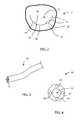
- the heart 2includes a mitral valve 6 that has a valve annulus 4 .
- the mitral valve 6may fail to close completely when it should during a heartbeat.
- the normal mitral valve 6opens when the left ventricle 8 relaxes (diastole), allowing blood from the left atrium 10 to fill the decompressed left ventricle 8 .
- the increase in pressure within the left ventricle 8causes the mitral valve 6 to close, preventing blood from leaking into the left atrium 10 and assuring that all of the blood leaving the left ventricle 8 (the stroke volume) is ejected through the mitral valve 6 into the aorta 12 and then to the body.
- the mitral valve 6has two leaflets.
- the anterior leaflet 14has a semicircular shape and attached to approximately two-fifths of the perimeter of the valve annulus 4 .
- the free edge 15 of the anterior leaflet 14is typically continuous, without indentations.
- the posterior leaflet 16 of the mitral valve 6is attached to approximately three-fifths of the perimeter of the valve annulus 4 .
- the posterior leaflet 16has three segments: the anterior scallop 18 , the middle scallop 20 , and the posterior scallop 22 .
- the anterior scallop 18is divided from the middle scallop 20 by a first indentation 24
- the middle scallop 20is divided from the posterior scallop 22 by a second indentation 26 .
- the indentations 24 , 26aid in posterior leaflet 16 opening during diastole.
- the free edge 24 of the posterior leaflet 16contacts the free edge 15 of the anterior leaflet 14 when the mitral valve 6 is closed.
- the height of the posterior leaflet 16is typically less than the height of the anterior leaflet 14 ; however, both leaflets 14 , 16 typically have generally similar surface areas.
- FIG. 1is a cross-section view of a human heart.
- FIG. 2is a top view of a mitral valve of the human heart of FIG. 1 .
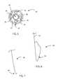
- FIG. 3is a perspective view of a guide catheter.
- FIG. 4is an end view of the distal end of a first example of the guide catheter of FIG. 3 .
- FIG. 5is an end view of the distal end of a second example of the guide catheter of FIG. 3 .
- FIG. 6is a perspective view of an exemplary sling.
- FIG. 7is a perspective view of an exemplary hook.
- FIG. 8is a perspective view of an exemplary clip applier.
- FIG. 9is a perspective view of an exemplary clip.
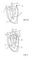
- FIG. 10is a perspective view of a step of a method of treating the mitral valve.
- FIG. 11is a perspective view of another step of a method of treating the mitral valve.
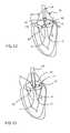
- FIG. 12is a perspective view of another step of a method of treating the mitral valve.
- FIG. 13is a perspective view of another step of a method of treating the mitral valve.
- FIG. 14is a perspective view of another step of a method of treating the mitral valve.
- FIG. 15is a perspective view of a treated mitral valve with a clip holding the leaflets thereof.
- the guide catheter 30may be generally cylindrical in shape, and is flexible enough to be advanced through the vasculature of a patient.
- the surface of the guide catheter 30is atraumatic, in order to prevent injury to the vasculature of a patient.
- the guide catheter 30may be fabricated from any suitable material or combination of materials.
- the guide catheter 30may have five channels within.
- a clip channel 32may be the largest channel in the guide catheter 30 , and may be substantially concentric within the guide catheter 30 .
- the clip channel 32may be generally cylindrical, with a substantially circular cross-section. However, the clip channel 32 may be shaped differently and/or offset from the longitudinal centerline of the guide catheter 30 .
- Two sling channels 34may be positioned radially outward from the clip channel 32 , on opposed sides of the clip channel 32 .
- Two hook channels 36may be positioned radially outward from the clip channel 32 , on opposed sides of the clip channel 32 .
- the hook channels 36may be arranged substantially ninety arcuate degrees away from the sling channels 34 , such that the channels 34 , 36 are substantially evenly spaced around the clip channel 32 .
- the channels 34 , 36may be positioned at any other suitable angular positions relative to one another; and the channels 32 , 34 , 36 as a group may be arranged in any other suitable manner.
- one or more of the channels 32 , 34 , 36may be lumens defined within a solid or partially solid guide catheter 30 . If so, any such channel may be fabricated within the guide catheter 30 in any suitable manner, such as by drilling, boring, or laser-cutting, or the guide catheter 30 may be fabricated in such a manner that any such channel is devoid of material within throughout the fabrication process.
- one or more of the channels 32 , 34 , 36may be individual tubes positioned within the guide catheter 30 . If so, the channels 34 , 36 may be positioned between the outer surface 38 of the clip channel 32 and the inner surface 42 of an outer sheath 40 .
- the channels 34 , 36also may support the clip channel 32 within the lumen 44 of the outer sheath 44 .
- the channels 32 , 34 , 36may be connected to the outer sheath 40 in any suitable manner.
- the guide catheter 30may be fabricated in any other suitable manner that results in a suitable number of channels defined therethrough.
- each sling 50may be utilized in conjunction with the guide catheter 30 .
- Each sling 50may include a broad section 52 and an extension 54 extending proximal to the broad section 52 .
- the broad section 52may be substantially D-shaped, as shown in FIG. 6 , or may have any other suitable shape.
- the broad section 52may be a closed loop, or may be open at least in party.
- the broad section 52may lie in substantially a single plane, but need not do so.
- the sling 50may be fabricated from one or more pieces of superelastic wire, such as wire composed of nickel-titanium alloy.
- the sling 50may be fabricated from spring steel or other metal that is not superelastic, or may be fabricated from any suitable nonmetallic material.
- the extension 54is configured to extend through a corresponding sling channel 34 in the guide catheter 30 .
- the sling 50is collapsible, such that the sling 50 in its entirety can be held partially or completely within a corresponding sling channel 34 in an initial position, as described in greater detail below.
- At least one hook 60may be utilized in conjunction with the guide catheter 30 .
- Each hook 60may be curved or angled at the distal end thereof, such that the free end of the hook 60 is oriented at least partially in the proximal direction.
- the hook 60may be J-shaped, or may be shaped in any other suitable manner.
- the hook 60may be fabricated from one or more pieces of superelastic wire, such as wire composed of nickel-titanium alloy. However, the hook 60 may be fabricated from spring steel or other metal that is not superelastic, or may be fabricated from any suitable nonmetallic material.
- the proximal end of the hook 60is configured to extend through a corresponding hook channel 36 in the guide catheter 30 .
- the hook 60is collapsible, such that the hook 60 can be held partially or completely within a corresponding hook channel 36 in an initial position, as described in greater detail below.
- One or more hooks 60may include a closing or locking feature at the distal end thereof that can be automatically or remotely actuated to open and close as needed.
- a clip appliermay be utilized in conjunction with the clip channel 32 .
- the clip appliermay be substantially as set forth in U.S. Pat. App. Pub. No. 2009/0093826 of Warder-Gabaldon et. al., filed on Oct. 5, 2007 (the “Clip Publication”), which is hereby incorporated by reference in its entirety.
- the clip applier 70may be configured to splay and then deploy a clip 72 , as set forth in the Clip Publication.
- the clip 72may have four tines 74 arranged in an X configuration.
- the clip 72may have tines 74 arranged in any other suitable configuration, and/or may include a different number of tines 74 .
- the clip applier 70is configured to be held partially or completely with the corresponding clip channel 32 of the guide catheter 30 in an initial position, as described in greater detail below.
- the distal end 31 of the guide catheter 30is advanced through the left atrium 10 into the left ventricle 8 , through the mitral valve 6 .
- the guide catheter 30may be introduced into the left atrium 10 through a transseptal puncture, through the patient's vasculature, or in any other suitable manner that provides access to the left atrium 10 for the guide catheter 30 .
- the heart 2advantageously continues to beat during and after introduction of the guide catheter 30 thereinto; however, the heart 2 may be stopped and the patient placed on a heart-lung machine at the discretion of the user.
- each sling 50is each advanced distally out of the corresponding sling channels 34 in the guide catheter 30 .
- Such advancementmay be performed in any suitable manner, such as by pushing the extension 54 distally either by hand or by application of force through a handle (not shown).
- the broad section 52 of each sling 50is initially compressed by and constrained by contact with the interior of the corresponding sling channel 34 such that each sling 50 can be held within the circumference of the guide catheter 30 .
- its broad section 52advances out of the corresponding sling channel 34 such that the broad section 52 is no longer constrained by the corresponding sling channel 34 .
- the broad section 52self-expands within the left ventricle 8 .
- the guide catheter 30actively expands each broad section 52 within the left ventricle 8 .
- two slings 50are deployed from the guide catheter 30 and expanded.
- the slings 50expand from the left ventricle 8 through the mitral valve 6 and into the left atrium 10 .
- the slings 50generally center the guide catheter 30 within the mitral valve 6 .
- the guide catheter 30may then be retracted such that its distal end 31 is positioned in the left atrium 10 .
- the slings 50substantially remain in position relative to the left ventricle 8 , mitral valve 6 and left atrium 10 due to the outward force exerted by the slings against the inner surfaces of the left ventricle 8 and the left atrium 10 , as well as the lateral ends 82 of the opening 80 of the mitral valve 6 .
- the guide catheter 30slides along the extensions 54 of the slings 50 as the broad sections 52 of the slings 50 remain generally in place in the heart 2 .
- the guide catheter 30may be retracted using ultrasound, fluoroscopy, or any other suitable imaging method to determine the location of the distal end 31 of the guide catheter 30 .
- one or more hooks 60are each advanced distally out of the corresponding hook channels 34 in the guide catheter 30 .
- Such advancementmay be performed in any suitable manner, such as by pushing each hook 60 distally either by hand or by application of force through a handle (not shown).
- the distal J-portion 64 of at least one hook 60may be narrower than the corresponding hook channel 36 in the guide catheter 30 , such that the J-portion 64 of at least one hook 60 is not substantially compressed while that hook 60 is in its initial position within the hook channel 36 in the guide catheter 30 .
- the J-shaped portion 64 of at least one hook 60may be wider than the corresponding hook channel 36 , such that the J-shaped portion 64 is initially compressed by and constrained by contact with the interior of the corresponding hook channel 36 such that each J-shaped portion 64 can be held within the circumference of the guide catheter 30 .
- the J-shaped portion 64 of each hook 60advances out of the corresponding hook channel 36 in the guide catheter 30 .
- the hook 64may simply move out of the hook channel 36 without substantially changing its size or shape.
- each hook 60has a J-shaped portion 64 or similarly shaped portion at the distal end thereof, the distal end of each hook 60 is substantially blunt, and thereby passes through the mitral valve 6 without engaging or damaging the tissue of the mitral valve 6 .
- each retracted hook 60may grab the edge of a corresponding leaflet 14 , 16 of the mitral valve 6 .
- Thismay require multiple attempts, and may be controlled using ultrasound, fluoroscopy, or any other suitable imaging device or technique.
- Either leaflet 14 , 16may be engaged first.
- the physicianchooses to engage the anterior leaflet 14 first. Once that hook 60 has engaged the anterior leaflet 14 , the hook 60 is retracted toward the guide catheter 30 , moving the edge of the anterior leaflet 14 to its closed position—that is, the position the anterior leaflet 14 would assume during normal closure of the mitral valve 6 .
- the hook 60may include a locking feature (not shown) that allows the physician to manually lock the J-shaped portion 64 of the hook 60 after it engages the anterior leaflet 14 , or may include an automatic locking feature that automatically locks the J-shaped portion 64 of the hook 60 after it engages the anterior leaflet 14 . Such a locking feature would prevent the leaflet 14 from disengaging from the hook 60 .
- the posterior leaflet 16may be engaged with a second hook 60 in substantially the same manner in which the anterior leaflet 14 was engaged, as described above.
- the hook 60is retracted toward the guide catheter 30 , moving the edge of the posterior leaflet 16 to its closed position—that is, the position the posterior leaflet 16 would assume during normal closure of the mitral valve 6 .
- the hooks 60can be manipulated substantially simultaneously to engage leaflets 14 , 16 at substantially the same time, rather than sequentially as described above. Referring also to FIG. 12 , the hooks 60 thereby hold the leaflets 14 , 16 in a closed position that mimics the position in which the leaflets 14 , 16 would be held by a clip.
- the physicianmay utilize ultrasound, fluoroscopy, or any other suitable imaging technique, and/or a nonimaging technique such as flow measurement, to view and/or measure the mitral valve 6 and determine the impact of fixing the leaflets 14 , 16 in substantially the position in which they are held by the hooks 60 . If the imaging and/or measurement does not indicate sufficient reduction of mitral insufficiency, the physician can release the leaflets 14 , 16 from the hooks 60 , such as by moving the hooks 60 distally. The physician may then reorient the guide catheter 30 and capture the leaflets 14 , 16 again, as described above, where the hooks 60 engage different portions of the leaflets 14 , 16 .
- the slings 50may stretch the opening 80 of the mitral valve 6 by moving the ends 82 of the opening 80 away from one another. By stretching the mitral valve 6 , the leaflets 14 , 16 may move closer to one another, rendering it easier to capture them with the hooks 60 .
- the broad sections 52 of the slings 50may form substantially a single plane, where the sling channels 34 are oriented substantially along a line that includes the centerline of the guide catheter 30 .
- the hook channels 36may be oriented along a line that includes the centerline of the guide catheter 30 , where that line is substantially perpendicular to the line formed by the sling channels 34 and the centerline of the guide catheter 30 .
- the hook channels 36 and sling channels 34may be substantially evenly spaced along ninety-degree increments along the circumference of the guide catheter 30 . Further, in this way the hooks 60 may be oriented relative to the opening 80 in the mitral valve 6 in a manner that maximizes the ease of engagement between the hooks 60 and the leaflets 14 , 16 .
- the clip applier 70is advanced distally along the clip channel 32 of the guide catheter 30 , at least partially out of the distal end 31 of the guide catheter 30 .
- the clip applier 70is then actuated to splay the clip 72 , as described in the Clip Publication.
- the distal ends of the tines 74 of the clip 72each move in a direction having a component of motion away from the longitudinal centerline of the clip 72 .
- This deformation of the clip 72may be referred to as “splaying.”
- the clip 72is plastically deformed during splaying, such that after splaying the tines 74 of the clip 72 remain in the splayed configuration on their own, without requiring the application of force from the clip applier 70 to maintain the tines 74 in the splayed configuration.
- the clip 72may be splayed in an elastic or superelastic manner. The splayed clip 72 is still held by the clip applier 70 , and the distal ends of the tines 74 extend radially outward beyond the outer perimeter of the clip applier 70 and of the guide catheter 30 .
- the leaflets 14 , 16 and the splayed clip 72are brought into contact with one another. This may be performed by moving the clip applier 70 distally, thereby penetrating the distal ends of at least two tines 74 into the leaflets 14 , 16 .
- the hooks 60may be retracted proximally, bringing the leaflets 14 , 16 into contact with the tines 74 and causing the tines 74 to penetrate the leaflets 14 , 16 .
- the clip applier 70may be moved distally and the hooks 60 may be moved proximally in order to penetrate the tines 74 through the leaflets 14 , 16 .
- all of the tines 74penetrate the leaflets 14 , 16 .
- the clip 72has multiple tines 74 , it is not necessary for all of the tines 74 to penetrate the leaflets 14 , 16 ; rather, one or more tines 74 may enter the opening 80 in the mitral valve 6 .
- the clip 72may be configured to have two tines 74 , and the clip applier 70 may be actuated in a manner that ensures that one tine 74 penetrates each leaflet 14 , 16 .
- the clip 72is closed, substantially as described in the Clip Publication.
- the leaflets 14 , 16are firmly and permanently connected together by the clip 72 .
- the clip 72engages the leaflets 14 , 16 approximately at the center of the mitral valve 6 .
- the clip 72may be placed at any location along the leaflets 14 , 16 , at the discretion of the physician.
- the physiciancan retract the clip applier 70 proximally a small amount, to ensure that the clip 72 has penetrated the leaflets 14 , 16 and firmly attached them. Referring also to FIG.
- the clip applier 70releases the closed clip 72 , substantially as described in the Clip Publication.
- the clip applier 70is then withdrawn proximally, partially or completely into the clip channel 32 in the guide catheter 30 .
- the hooks 60are released from the leaflets 14 , 16 in any suitable manner and withdrawn into the hook channels 36 in the guide catheter.
- the guide catheter 30is then withdrawn, leaving the closed clip 72 in the mitral valve 6 .
- a double orifice mitral valve 6has thus been created, which is suitable for treating mitral insufficiency.
Landscapes
- Health & Medical Sciences (AREA)
- Life Sciences & Earth Sciences (AREA)
- Surgery (AREA)
- Veterinary Medicine (AREA)
- General Health & Medical Sciences (AREA)
- Biomedical Technology (AREA)
- Heart & Thoracic Surgery (AREA)
- Engineering & Computer Science (AREA)
- Public Health (AREA)
- Animal Behavior & Ethology (AREA)
- Medical Informatics (AREA)
- Molecular Biology (AREA)
- Nuclear Medicine, Radiotherapy & Molecular Imaging (AREA)
- Prostheses (AREA)
- Cardiology (AREA)
- Surgical Instruments (AREA)
- Oral & Maxillofacial Surgery (AREA)
- Transplantation (AREA)
- Vascular Medicine (AREA)
Abstract
Description
Claims (7)
Priority Applications (1)
| Application Number | Priority Date | Filing Date | Title |
|---|---|---|---|
| US13/951,873US8888794B2 (en) | 2010-06-16 | 2013-07-26 | Mitral valve treatment |
Applications Claiming Priority (2)
| Application Number | Priority Date | Filing Date | Title |
|---|---|---|---|
| US12/817,100US8496671B1 (en) | 2010-06-16 | 2010-06-16 | Mitral valve treatment |
| US13/951,873US8888794B2 (en) | 2010-06-16 | 2013-07-26 | Mitral valve treatment |
Related Parent Applications (1)
| Application Number | Title | Priority Date | Filing Date |
|---|---|---|---|
| US12/817,100DivisionUS8496671B1 (en) | 2010-06-16 | 2010-06-16 | Mitral valve treatment |
Publications (2)
| Publication Number | Publication Date |
|---|---|
| US20130338684A1 US20130338684A1 (en) | 2013-12-19 |
| US8888794B2true US8888794B2 (en) | 2014-11-18 |
Family
ID=48808639
Family Applications (2)
| Application Number | Title | Priority Date | Filing Date |
|---|---|---|---|
| US12/817,100Expired - Fee RelatedUS8496671B1 (en) | 2010-06-16 | 2010-06-16 | Mitral valve treatment |
| US13/951,873ActiveUS8888794B2 (en) | 2010-06-16 | 2013-07-26 | Mitral valve treatment |
Family Applications Before (1)
| Application Number | Title | Priority Date | Filing Date |
|---|---|---|---|
| US12/817,100Expired - Fee RelatedUS8496671B1 (en) | 2010-06-16 | 2010-06-16 | Mitral valve treatment |
Country Status (1)
| Country | Link |
|---|---|
| US (2) | US8496671B1 (en) |
Cited By (1)
| Publication number | Priority date | Publication date | Assignee | Title |
|---|---|---|---|---|
| US9681951B2 (en) | 2013-03-14 | 2017-06-20 | Edwards Lifesciences Cardiaq Llc | Prosthesis with outer skirt and anchors |
Families Citing this family (25)
| Publication number | Priority date | Publication date | Assignee | Title |
|---|---|---|---|---|
| CA2822381C (en) | 2010-12-23 | 2019-04-02 | Foundry Newco Xii, Inc. | System for mitral valve repair and replacement |
| JP5872692B2 (en) | 2011-06-21 | 2016-03-01 | トゥエルヴ, インコーポレイテッド | Artificial therapy device |
| US9039757B2 (en) | 2011-10-19 | 2015-05-26 | Twelve, Inc. | Prosthetic heart valve devices, prosthetic mitral valves and associated systems and methods |
| US11202704B2 (en) | 2011-10-19 | 2021-12-21 | Twelve, Inc. | Prosthetic heart valve devices, prosthetic mitral valves and associated systems and methods |
| US9655722B2 (en) | 2011-10-19 | 2017-05-23 | Twelve, Inc. | Prosthetic heart valve devices, prosthetic mitral valves and associated systems and methods |
| JP6133309B2 (en) | 2011-10-19 | 2017-05-24 | トゥエルヴ, インコーポレイテッド | Prosthetic heart valve device |
| US9763780B2 (en) | 2011-10-19 | 2017-09-19 | Twelve, Inc. | Devices, systems and methods for heart valve replacement |
| EA201400478A1 (en) | 2011-10-19 | 2014-10-30 | Твелв, Инк. | DEVICES, SYSTEMS AND METHODS OF PROTESIZING THE HEART VALVE |
| US9579198B2 (en) | 2012-03-01 | 2017-02-28 | Twelve, Inc. | Hydraulic delivery systems for prosthetic heart valve devices and associated methods |
| AU2014268631B2 (en) | 2013-05-20 | 2019-08-01 | Twelve, Inc. | Implantable heart valve devices, mitral valve repair devices and associated systems and methods |
| US10238490B2 (en) | 2015-08-21 | 2019-03-26 | Twelve, Inc. | Implant heart valve devices, mitral valve repair devices and associated systems and methods |
| WO2017189276A1 (en) | 2016-04-29 | 2017-11-02 | Medtronic Vascular Inc. | Prosthetic heart valve devices with tethered anchors and associated systems and methods |
| US10398552B2 (en) | 2016-11-15 | 2019-09-03 | Abbott Cardiovascular Systems Inc. | Fixation devices, systems and methods for heart valve leaf repair |
| US10905554B2 (en) | 2017-01-05 | 2021-02-02 | Edwards Lifesciences Corporation | Heart valve coaptation device |
| US10433961B2 (en) | 2017-04-18 | 2019-10-08 | Twelve, Inc. | Delivery systems with tethers for prosthetic heart valve devices and associated methods |
| US10575950B2 (en) | 2017-04-18 | 2020-03-03 | Twelve, Inc. | Hydraulic systems for delivering prosthetic heart valve devices and associated methods |
| US10702378B2 (en) | 2017-04-18 | 2020-07-07 | Twelve, Inc. | Prosthetic heart valve device and associated systems and methods |
| US10792151B2 (en) | 2017-05-11 | 2020-10-06 | Twelve, Inc. | Delivery systems for delivering prosthetic heart valve devices and associated methods |
| US10646338B2 (en) | 2017-06-02 | 2020-05-12 | Twelve, Inc. | Delivery systems with telescoping capsules for deploying prosthetic heart valve devices and associated methods |
| US10709591B2 (en) | 2017-06-06 | 2020-07-14 | Twelve, Inc. | Crimping device and method for loading stents and prosthetic heart valves |
| US10729541B2 (en) | 2017-07-06 | 2020-08-04 | Twelve, Inc. | Prosthetic heart valve devices and associated systems and methods |
| US10786352B2 (en) | 2017-07-06 | 2020-09-29 | Twelve, Inc. | Prosthetic heart valve devices and associated systems and methods |
| CN114762635B (en)* | 2021-01-15 | 2025-05-30 | 杭州德晋医疗科技有限公司 | Fully fitted valve clipping device and valve clipping system |
| US20240415643A1 (en)* | 2020-04-24 | 2024-12-19 | ReValve Solutions Inc. | Devices, systems, and methods for a valve replacement |
| AU2021296932A1 (en)* | 2020-06-26 | 2023-02-16 | ReValve Solutions Inc. | Devices, systems, and methods for a heart-valve annulus reinforcer |
Citations (39)
| Publication number | Priority date | Publication date | Assignee | Title |
|---|---|---|---|---|
| US4586503A (en) | 1983-12-01 | 1986-05-06 | University Of New Mexico | Surgical microclip |
| US4932965A (en) | 1988-12-19 | 1990-06-12 | Phillips Steven J | Artificial valve, and needle and suture holder and method of using same |
| US4950258A (en)* | 1988-01-28 | 1990-08-21 | Japan Medical Supply Co., Ltd. | Plastic molded articles with shape memory property |
| US5242457A (en) | 1992-05-08 | 1993-09-07 | Ethicon, Inc. | Surgical instrument and staples for applying purse string sutures |
| US5891160A (en) | 1996-02-23 | 1999-04-06 | Cardiovascular Technologies, Llc | Fastener delivery and deployment mechanism and method for placing the fastener in minimally invasive surgery |
| US6001127A (en) | 1998-03-31 | 1999-12-14 | St. Jude Medical, Inc. | Annuloplasty ring holder |
| US6254615B1 (en) | 1995-02-24 | 2001-07-03 | Heartport, Inc. | Surgical clips and methods for tissue approximation |
| US6409758B2 (en) | 2000-07-27 | 2002-06-25 | Edwards Lifesciences Corporation | Heart valve holder for constricting the valve commissures and methods of use |
| US6413274B1 (en) | 1998-01-27 | 2002-07-02 | United States Surgical Corporation | Stapling apparatus and method for heart valve replacement |
| US6506197B1 (en) | 2000-11-15 | 2003-01-14 | Ethicon, Inc. | Surgical method for affixing a valve to a heart using a looped suture combination |
| US20030032981A1 (en)* | 2000-09-01 | 2003-02-13 | Glenn Kanner | Advanced wound site management systems and methods |
| US20030191479A1 (en)* | 2002-04-03 | 2003-10-09 | Thornton Sally C. | Body lumen closure |
| US6695866B1 (en) | 1998-07-15 | 2004-02-24 | St. Jude Medical, Inc. | Mitral and tricuspid valve repair |
| US6726716B2 (en) | 2001-08-24 | 2004-04-27 | Edwards Lifesciences Corporation | Self-molding annuloplasty ring |
| US6730118B2 (en) | 2001-10-11 | 2004-05-04 | Percutaneous Valve Technologies, Inc. | Implantable prosthetic valve |
| US6752813B2 (en)* | 1999-04-09 | 2004-06-22 | Evalve, Inc. | Methods and devices for capturing and fixing leaflets in valve repair |
| US20040167620A1 (en)* | 2000-07-06 | 2004-08-26 | Medtentia | Annuloplasty devices and related heart valve repair methods |
| US20050065601A1 (en) | 2002-04-18 | 2005-03-24 | Coalescent Surgical, Inc. | Annuloplasty apparatus and methods |
| US20050080454A1 (en)* | 2003-10-08 | 2005-04-14 | Drews Michael J. | Attachment device and methods of using the same |
| US20050267493A1 (en)* | 2001-02-06 | 2005-12-01 | Schreck Stefan G | Method and system for tissue repair using dual catheters |
| US6986775B2 (en) | 2002-06-13 | 2006-01-17 | Guided Delivery Systems, Inc. | Devices and methods for heart valve repair |
| US20060064116A1 (en)* | 1999-10-21 | 2006-03-23 | Allen William J | Minimally invasive mitral valve repair method and apparatus |
| US20060106456A9 (en) | 2002-10-01 | 2006-05-18 | Ample Medical, Inc. | Devices, systems, and methods for reshaping a heart valve annulus |
| US7223289B2 (en) | 2002-04-16 | 2007-05-29 | Warsaw Orthopedic, Inc. | Annulus repair systems and techniques |
| US20070129794A1 (en) | 2005-10-05 | 2007-06-07 | Fidel Realyvasquez | Method and apparatus for prosthesis attachment using discrete elements |
| US7285131B1 (en) | 1999-07-28 | 2007-10-23 | Cardica, Inc. | System for performing anastomosis |
| US20080033241A1 (en)* | 2006-08-01 | 2008-02-07 | Ruey-Feng Peh | Left atrial appendage closure |
| US20080051807A1 (en)* | 1999-04-09 | 2008-02-28 | Evalve, Inc. | Methods and apparatus for cardiac valve repair |
| US7344544B2 (en) | 2005-03-28 | 2008-03-18 | Cardica, Inc. | Vascular closure system |
| US20080188873A1 (en)* | 2005-01-21 | 2008-08-07 | Giovanni Speziali | Thorascopic Heart Valve Repair Method and Apparatus |
| US7473258B2 (en) | 2007-03-08 | 2009-01-06 | Cardica, Inc. | Surgical stapler |
| US7485142B2 (en) | 2001-12-21 | 2009-02-03 | Simcha Milo | Implantation system for annuloplasty rings |
| US7513909B2 (en) | 2005-04-08 | 2009-04-07 | Arbor Surgical Technologies, Inc. | Two-piece prosthetic valves with snap-in connection and methods for use |
| US7658763B2 (en) | 2000-12-21 | 2010-02-09 | Edwards Lifesciences Corporation | Heart valve holder and method for resisting suture looping |
| US7887583B2 (en) | 2000-09-20 | 2011-02-15 | Mvrx, Inc. | Heart valve annulus device and method of using same |
| US20110190793A1 (en)* | 2010-01-29 | 2011-08-04 | Med-Venture Investments, Llc | Methods and apparatuses for suturing of cardiac openings |
| US8052748B2 (en) | 2004-05-14 | 2011-11-08 | St. Jude Medical, Inc. | Systems and methods for holding annuloplasty rings |
| US8070804B2 (en)* | 2002-11-15 | 2011-12-06 | Abbott Cardiovascular Systems Inc. | Apparatus and methods for heart valve repair |
| US8512403B2 (en) | 2003-05-20 | 2013-08-20 | The Cleveland Clinic Foundation | Annuloplasty ring with wing members for repair of a cardiac valve |
- 2010
- 2010-06-16USUS12/817,100patent/US8496671B1/ennot_activeExpired - Fee Related
- 2013
- 2013-07-26USUS13/951,873patent/US8888794B2/enactiveActive
Patent Citations (46)
| Publication number | Priority date | Publication date | Assignee | Title |
|---|---|---|---|---|
| US4586503A (en) | 1983-12-01 | 1986-05-06 | University Of New Mexico | Surgical microclip |
| US4950258A (en)* | 1988-01-28 | 1990-08-21 | Japan Medical Supply Co., Ltd. | Plastic molded articles with shape memory property |
| US4932965A (en) | 1988-12-19 | 1990-06-12 | Phillips Steven J | Artificial valve, and needle and suture holder and method of using same |
| US5242457A (en) | 1992-05-08 | 1993-09-07 | Ethicon, Inc. | Surgical instrument and staples for applying purse string sutures |
| US6254615B1 (en) | 1995-02-24 | 2001-07-03 | Heartport, Inc. | Surgical clips and methods for tissue approximation |
| US5891160A (en) | 1996-02-23 | 1999-04-06 | Cardiovascular Technologies, Llc | Fastener delivery and deployment mechanism and method for placing the fastener in minimally invasive surgery |
| US6413274B1 (en) | 1998-01-27 | 2002-07-02 | United States Surgical Corporation | Stapling apparatus and method for heart valve replacement |
| US6001127A (en) | 1998-03-31 | 1999-12-14 | St. Jude Medical, Inc. | Annuloplasty ring holder |
| US6695866B1 (en) | 1998-07-15 | 2004-02-24 | St. Jude Medical, Inc. | Mitral and tricuspid valve repair |
| US20080051807A1 (en)* | 1999-04-09 | 2008-02-28 | Evalve, Inc. | Methods and apparatus for cardiac valve repair |
| US6752813B2 (en)* | 1999-04-09 | 2004-06-22 | Evalve, Inc. | Methods and devices for capturing and fixing leaflets in valve repair |
| US8187299B2 (en) | 1999-04-09 | 2012-05-29 | Evalve, Inc. | Methods and apparatus for cardiac valve repair |
| US7285131B1 (en) | 1999-07-28 | 2007-10-23 | Cardica, Inc. | System for performing anastomosis |
| US7744609B2 (en)* | 1999-10-21 | 2010-06-29 | Edwards Lifesciences Corporation | Minimally invasive mitral valve repair method and apparatus |
| US7758595B2 (en) | 1999-10-21 | 2010-07-20 | Edwards Lifesciences Corporation | Minimally invasive mitral valve repair method and apparatus |
| US20100234813A1 (en)* | 1999-10-21 | 2010-09-16 | Allen William J | Minimally invasive mitral valve repair method and apparatus |
| US7112207B2 (en)* | 1999-10-21 | 2006-09-26 | Edwards Lifesciences Corporation | Minimally invasive mitral valve repair method and apparatus |
| US20060064116A1 (en)* | 1999-10-21 | 2006-03-23 | Allen William J | Minimally invasive mitral valve repair method and apparatus |
| US20040167620A1 (en)* | 2000-07-06 | 2004-08-26 | Medtentia | Annuloplasty devices and related heart valve repair methods |
| US6964684B2 (en) | 2000-07-06 | 2005-11-15 | Medtentia | Annuloplasty devices and related heart valve repair methods |
| US6409758B2 (en) | 2000-07-27 | 2002-06-25 | Edwards Lifesciences Corporation | Heart valve holder for constricting the valve commissures and methods of use |
| US6767356B2 (en) | 2000-09-01 | 2004-07-27 | Angiolink Corporation | Advanced wound site management systems and methods |
| US20030032981A1 (en)* | 2000-09-01 | 2003-02-13 | Glenn Kanner | Advanced wound site management systems and methods |
| US7887583B2 (en) | 2000-09-20 | 2011-02-15 | Mvrx, Inc. | Heart valve annulus device and method of using same |
| US6506197B1 (en) | 2000-11-15 | 2003-01-14 | Ethicon, Inc. | Surgical method for affixing a valve to a heart using a looped suture combination |
| US7658763B2 (en) | 2000-12-21 | 2010-02-09 | Edwards Lifesciences Corporation | Heart valve holder and method for resisting suture looping |
| US20050267493A1 (en)* | 2001-02-06 | 2005-12-01 | Schreck Stefan G | Method and system for tissue repair using dual catheters |
| US6726716B2 (en) | 2001-08-24 | 2004-04-27 | Edwards Lifesciences Corporation | Self-molding annuloplasty ring |
| US6730118B2 (en) | 2001-10-11 | 2004-05-04 | Percutaneous Valve Technologies, Inc. | Implantable prosthetic valve |
| US7485142B2 (en) | 2001-12-21 | 2009-02-03 | Simcha Milo | Implantation system for annuloplasty rings |
| US20030191479A1 (en)* | 2002-04-03 | 2003-10-09 | Thornton Sally C. | Body lumen closure |
| US7223289B2 (en) | 2002-04-16 | 2007-05-29 | Warsaw Orthopedic, Inc. | Annulus repair systems and techniques |
| US20050065601A1 (en) | 2002-04-18 | 2005-03-24 | Coalescent Surgical, Inc. | Annuloplasty apparatus and methods |
| US6986775B2 (en) | 2002-06-13 | 2006-01-17 | Guided Delivery Systems, Inc. | Devices and methods for heart valve repair |
| US20060106456A9 (en) | 2002-10-01 | 2006-05-18 | Ample Medical, Inc. | Devices, systems, and methods for reshaping a heart valve annulus |
| US8070804B2 (en)* | 2002-11-15 | 2011-12-06 | Abbott Cardiovascular Systems Inc. | Apparatus and methods for heart valve repair |
| US8512403B2 (en) | 2003-05-20 | 2013-08-20 | The Cleveland Clinic Foundation | Annuloplasty ring with wing members for repair of a cardiac valve |
| US20050080454A1 (en)* | 2003-10-08 | 2005-04-14 | Drews Michael J. | Attachment device and methods of using the same |
| US8052748B2 (en) | 2004-05-14 | 2011-11-08 | St. Jude Medical, Inc. | Systems and methods for holding annuloplasty rings |
| US20080188873A1 (en)* | 2005-01-21 | 2008-08-07 | Giovanni Speziali | Thorascopic Heart Valve Repair Method and Apparatus |
| US7344544B2 (en) | 2005-03-28 | 2008-03-18 | Cardica, Inc. | Vascular closure system |
| US7513909B2 (en) | 2005-04-08 | 2009-04-07 | Arbor Surgical Technologies, Inc. | Two-piece prosthetic valves with snap-in connection and methods for use |
| US20070129794A1 (en) | 2005-10-05 | 2007-06-07 | Fidel Realyvasquez | Method and apparatus for prosthesis attachment using discrete elements |
| US20080033241A1 (en)* | 2006-08-01 | 2008-02-07 | Ruey-Feng Peh | Left atrial appendage closure |
| US7473258B2 (en) | 2007-03-08 | 2009-01-06 | Cardica, Inc. | Surgical stapler |
| US20110190793A1 (en)* | 2010-01-29 | 2011-08-04 | Med-Venture Investments, Llc | Methods and apparatuses for suturing of cardiac openings |
Non-Patent Citations (1)
| Title |
|---|
| Regarding related patents and patent applications, see the section of the accompanying IDS letter entitled "Related Patents and Patent Applications" for further information. |
Cited By (1)
| Publication number | Priority date | Publication date | Assignee | Title |
|---|---|---|---|---|
| US9681951B2 (en) | 2013-03-14 | 2017-06-20 | Edwards Lifesciences Cardiaq Llc | Prosthesis with outer skirt and anchors |
Also Published As
| Publication number | Publication date |
|---|---|
| US20130338684A1 (en) | 2013-12-19 |
| US8496671B1 (en) | 2013-07-30 |
Similar Documents
| Publication | Publication Date | Title |
|---|---|---|
| US8888794B2 (en) | Mitral valve treatment | |
| US20240108327A1 (en) | Suturing devices and methods for suturing an anatomic valve | |
| US20250160816A1 (en) | Mitral valve fixation device removal devices and methods | |
| US20220192656A1 (en) | Device for heart repair | |
| JP7097351B2 (en) | Implant | |
| JP4558718B2 (en) | Mitral valve repair system and method for use | |
| CN112804968B (en) | Device for ventricular reshaping and heart valve reshaping | |
| AU2009202296B2 (en) | Mitral valve repair device and method for use | |
| US20190388084A1 (en) | Suturing devices and methods for suturing an anatomic valve | |
| EP3125777B1 (en) | Double orifice device for transcatheter mitral valve replacement | |
| EP3689261A1 (en) | System for closure of an internal opening in tissue, such as a trans-apical access opening | |
| CA2863939A1 (en) | A device and method for temporary or permanent suspension of an implantable scaffolding containing an orifice for placement of a prosthetic or bio-prosthetic valve | |
| US20240268957A1 (en) | Clip Delivery Catheter with Helical Multi-Lumen Extrusion for Improved Gripper Actuation and Methods of Making and Using Same | |
| GB2579387A (en) | Device for heart repair | |
| GB2579420A (en) | Device for heart repair | |
| CN113274167A (en) | Edge-to-edge repair device and edge-to-edge repair system |
Legal Events
| Date | Code | Title | Description |
|---|---|---|---|
| STCF | Information on status: patent grant | Free format text:PATENTED CASE | |
| AS | Assignment | Owner name:DEXTERA SURGICAL INC., CALIFORNIA Free format text:CHANGE OF NAME;ASSIGNOR:CARDICA, INC.;REEL/FRAME:040590/0152 Effective date:20160518 | |
| AS | Assignment | Owner name:AESCULAP AG, GERMANY Free format text:ASSET PURCHASE AGREEMENT;ASSIGNOR:AESDEX, LLC;REEL/FRAME:045870/0567 Effective date:20180220 Owner name:AESDEX, LLC, PENNSYLVANIA Free format text:ASSIGNMENT OF ASSIGNORS INTEREST;ASSIGNOR:DEXTERA SURGICAL INC.;REEL/FRAME:045870/0478 Effective date:20180214 | |
| FEPP | Fee payment procedure | Free format text:SURCHARGE FOR LATE PAYMENT, SMALL ENTITY (ORIGINAL EVENT CODE: M2554) | |
| MAFP | Maintenance fee payment | Free format text:PAYMENT OF MAINTENANCE FEE, 4TH YR, SMALL ENTITY (ORIGINAL EVENT CODE: M2551) Year of fee payment:4 | |
| FEPP | Fee payment procedure | Free format text:ENTITY STATUS SET TO UNDISCOUNTED (ORIGINAL EVENT CODE: BIG.); ENTITY STATUS OF PATENT OWNER: LARGE ENTITY | |
| MAFP | Maintenance fee payment | Free format text:PAYMENT OF MAINTENANCE FEE, 8TH YEAR, LARGE ENTITY (ORIGINAL EVENT CODE: M1552); ENTITY STATUS OF PATENT OWNER: LARGE ENTITY Year of fee payment:8 |