US8888646B2 - Two-mode continuously variable transmission - Google Patents
Two-mode continuously variable transmissionDownload PDFInfo
- Publication number
- US8888646B2 US8888646B2US13/570,428US201213570428AUS8888646B2US 8888646 B2US8888646 B2US 8888646B2US 201213570428 AUS201213570428 AUS 201213570428AUS 8888646 B2US8888646 B2US 8888646B2
- Authority
- US
- United States
- Prior art keywords
- gear
- mode
- cvt
- torque transmitting
- planetary gear
- Prior art date
- Legal status (The legal status is an assumption and is not a legal conclusion. Google has not performed a legal analysis and makes no representation as to the accuracy of the status listed.)
- Expired - Fee Related, expires
Links
Images


Classifications
- F—MECHANICAL ENGINEERING; LIGHTING; HEATING; WEAPONS; BLASTING
- F16—ENGINEERING ELEMENTS AND UNITS; GENERAL MEASURES FOR PRODUCING AND MAINTAINING EFFECTIVE FUNCTIONING OF MACHINES OR INSTALLATIONS; THERMAL INSULATION IN GENERAL
- F16H—GEARING
- F16H37/00—Combinations of mechanical gearings, not provided for in groups F16H1/00 - F16H35/00
- F16H37/02—Combinations of mechanical gearings, not provided for in groups F16H1/00 - F16H35/00 comprising essentially only toothed or friction gearings
- F16H37/021—Combinations of mechanical gearings, not provided for in groups F16H1/00 - F16H35/00 comprising essentially only toothed or friction gearings toothed gearing combined with continuously variable friction gearing
- F16H37/022—Combinations of mechanical gearings, not provided for in groups F16H1/00 - F16H35/00 comprising essentially only toothed or friction gearings toothed gearing combined with continuously variable friction gearing the toothed gearing having orbital motion
Definitions
- the present inventionrelates to continuously variable transmissions. More specifically, the present invention relates to continuously variable transmissions with two modes.
- a continuously variable transmissiontypically includes gearing that operatively couples a variator between a rotary power source, such as an engine or electric motor, and a final drive unit.
- the variatorincludes a rotary input disk and a rotary output disk which are able to steplessly or continuously vary the ratio of an input speed to an output speed (the “variator ratio”).
- the overall speed ratio provided by the CVTis a function of the variator ratio and the associated gearing.
- the output discincludes integrally formed gear teeth that are in mesh with and drive a corresponding gear. The gear in turn is functionally coupled to an output shaft or layshaft that is functionally coupled to the final drive unit.
- CVT designstypically have a single forward mode which limits the spread of the transmission ratio. Therefore, there is a need in the art for a CVT design that allows for large transmission ratio spreads.
- a continuously variable transmissionincludes a gearbox with two forward modes and a reverse mode.
- the gearboxincludes a plurality of gear members and further includes at least three torque transmitting devices such as, clutches and brakes that are selectively employed to engage various combinations of the gear members such that a particular combination is associated with one of the two forward modes and the reverse mode.
- FIG. 1is a schematic diagram of a powertrain for a motor vehicle in accordance with the principles the present invention
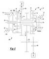
- FIG. 2is a close-up view of a gearbox of the powertrain shown in FIG. 1 ;
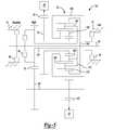
- FIG. 3is a close-up view of alternative gearbox for the powertrain shown in FIG. 1 in accordance with the principles of the present invention.
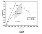
- FIG. 4is graph showing the relationship of the output speed ratio versus the variator speed ratio of the powertrain shown in FIG. 1 .
- the powertrain 10generally includes an engine 12 interconnected with a transmission 14 .
- the engine 12may be a conventional internal combustion engine or an electric motor, or any other type of prime mover, without departing from the scope of the present disclosure.
- the engine 12supplies a driving torque to the transmission 14 through, for example, a flexplate or other connecting device or a starting device (not shown) such as a hydrodynamic device or launch clutch.
- the transmission 14is a toroidal-type continuously variable transmission (CVT).
- the transmission 14includes a typically cast, metal housing 16 which encloses and protects the various components of the transmission 14 .
- the housing 16includes a variety of apertures, passageways, shoulders and flanges which position and support these components.
- the transmission 14includes a transmission input shaft 20 and a transmission output shaft 22 .
- Connected between the transmission input shaft 20 and the transmission output shaft 22is a gearbox 24 configured to provide forward and reverse speed or gear ratios between the transmission input shaft 20 and the transmission output shaft 22 and a variator 26 .
- the transmission input shaft 20is functionally interconnected with the engine 12 and receives input torque or power from the engine 12 .
- the transmission output shaft 22is preferably connected with a final drive unit 25 which includes, for example, a propshaft, a differential assembly, and drive axles connected to wheels, etc.
- the transmission input shaft 20is coupled to and provides drive torque to the gearbox 24 .
- the gearbox 24generally includes one or more gear sets, clutches and/or brakes, and shafts.
- the variator 26is illustrated as a toroidal race rolling type variator. However, it should be appreciated that various other types of variators may be employed without departing from the scope of the present invention.
- the variator 26includes a first input disc 28 and a second input disc 30 .
- the first input disk 28includes a toroidal outer surface or first input race 28 A and the second input disk 30 includes a toroidal outer surface or second input race 30 A.
- Disposed between the first and second input races 28 A, 30 Ais an output disk 32 .
- the output disk 32includes a toroidal outer surface or first output race 32 A and a toroidal outer surface or second output race 32 B.
- the first output race 32 Ais disposed opposite the first input race 28 A and the second output race 32 B is disposed opposite the second input race 30 A.
- the first input race 28 A and the first output race 32 Acooperate to define a first toroidal cavity 38 and the second input race 30 A and the second output race 32 B cooperate to define a second toroidal cavity 40 .
- Each of the disks 28 , 30 , and 32share a common rotational axis defined by a variator shaft 42 .
- the variator shaft 42is functionally interconnected to the transmission input shaft 20 and therefore receives drive torque from the engine 12 .
- the input disks 28 and 30are rotationally coupled to the variator shaft 42 and transfer drive torque to the output disk 32 via a plurality of rollers 50 and 52 .
- the first cavity 38includes the plurality of rollers 50 and second cavity 40 includes the plurality of rollers 52 .
- each of the first and second cavities 38 and 40include two or three rollers 50 and 52 , though it should be appreciated that any number of rollers may be employed without departing from the scope of the present invention.
- Each of the rollers 50 , 52are mounted for rotation about a roller axis and rolls upon the toroidal races 28 A, 32 A, 32 B, and 30 A of its associated input and output disks 28 , 30 , and 32 to transfer torque from the input disks 28 and 30 to the output disks 32 .
- Changes in variator torque ratioare achieved by precession of the rollers 50 , 52 such that the roller's axis is able to turn to change the inclination of the roller axis to the variator axis.
- Precession of the rollers 50 , 52results in changes of the radii of the paths traced upon the races 28 A, 32 A, 32 B, and 30 A by the rollers 50 , 52 and hence results in a change of variator drive ratio between the input disks 28 and 30 and the output disk 32 .
- a variator output gear 60is coupled to a distal portion 54 .
- the variator output transfer gear 60is intermeshed with the gearbox 24 .
- the gearbox 24is functionally interconnected with the transmission output shaft 22 through an output transfer gear 62 and supplies drive torque from the variator 26 and variator output transfer gear 60 to the transmission output shaft 22 and therefore the final drive unit 25 .
- the gearbox 24includes a first planetary gear set 64 and a second planetary gear set 66 positioned about a shaft 63 .
- the first planetary gear set 64includes a sun gear member 68 , a planet gear carrier member 70 , and a ring gear member 72 .
- the sun gear member 68is coupled to the input transfer gear 60 with a first shaft or interconnecting member 74 .
- the ring gear member 72is coupled to an intermediate transfer gear 76 with a second shaft or interconnecting member 78 .
- the planet gear carrier member 70is coupled to the shaft 63 and rotatably supports a set of planet gears 80 configured to intermesh with both the sun gear member 68 and the ring gear member 72 .
- the second planetary gear set 66includes a sun gear member 82 , a planet gear carrier member 84 , and a ring gear member 86 .
- the sun gear member 82is connected to a third shaft or interconnecting member 88
- the ring gear member 86is connected to a fourth shaft or interconnecting member 90 .
- the planet gear carrier member 84is coupled to the shaft 63 and rotatably supports a set of planet gears 85 configured to intermesh with both the sun gear member 82 and the ring gear member 86 .
- a first torque transmitting membersuch as, for example, a brake 92 selectively couples the third shaft or interconnecting member 88 to a stationary member or the transmission housing 16 .
- a second torque transmitting membersuch as, for example, a clutch 94 selectively couples the third shaft or interconnecting member 88 with the fourth shaft or interconnecting member 90 .
- a third torque transmitting membersuch as, for example, a brake 96 selectively couples the stationary member or the transmission housing 16 to the shaft 63 .
- the brake 92is operated to engage a first forward mode
- the clutch 94is operated to engage a second forward mode
- the brake 96is operated to engage a reverse mode of the transmission 14 .
- the brake 92When the transmission 14 is operated in the first forward mode (low mode), the brake 92 is engaged to hold the sun gear member 82 stationary. Input torque is transmitted from the variator 26 through the input transfer gear 60 to the ring gear member 86 . Accordingly, the rotational speed of the planet gear carrier member 84 , hence is set by planet gears 85 , is based on holding the sun gear member 82 and driving the ring gear member 86 . As such, the rotational speed of the planet gear carrier member 70 is the same as that of the planet gear carrier member 84 , and the output rotational speed of the gearbox 24 is equal to the ratio of the speed of the planet gear carrier member 70 to the speed of the sun gear 68 .
- the clutch 94When the transmission 14 is operated in the second forward mode (high mode), the clutch 94 is engaged. This couples the ring gear member 86 to the sun gear member 82 , such that the set of planet gears 85 has the same rotational speed as that of the planet gear carrier member 84 , resulting in the sun gear member 68 having the same rotational speed as the set of planet gears 80 .
- the gearbox 100includes a planetary gear set 101 positioned about the shaft 63 .
- the planetary gear set 101includes a ring gear member 172 , a first sun gear member 168 , a second sun gear member 185 , and a carrier member 170 .
- the first sun gear member 168is coupled to the input transfer gear 60 with the first shaft or interconnecting member 74 .
- the second sun gear member 185is connected to a second shaft or interconnecting member 188 .
- the ring gear member 172is coupled to the shaft 63 with a third shaft or interconnecting member 190 .
- the carrier member 170is coupled to the intermediate transfer gear 76 with a fourth shaft or interconnecting member 191 and rotatably supports a first pinion gear member 192 and a second pinion gear member 194 .
- the first pinion gear member 192is configured to intermesh with both the first sun gear member 168 and the second pinion gear member 194 .
- the second pinion gear member 194is configured to intermesh with the ring gear member 172 , the second sun gear member 185 , and the first pinion gear member 192 .
- a first torque transmitting membersuch as, for example, the brake 92 selectively couples the second shaft or interconnecting member 188 to a stationary member or the transmission housing 16 .
- a second torque transmitting membersuch as, for example, the clutch 94 selectively couples the fourth shaft or interconnecting member 191 with the shaft 63 .
- a third torque transmitting membersuch as, for example, the brake 96 selectively couples a stationary member or the transmission housing 16 to the shaft 63 .
- the brake 92is operated to engage a first forward mode (low mode)
- the clutch 94is operated to engage a second forward mode (high mode)
- the brake 96is operated to engage a reverse mode of the transmission 14 .
- the brake 96is engaged to prevent the ring gear member 172 from rotating.
- the input torque from the variator 26is transmitted to the first sun gear member 168 , which causes the first pinion gear 192 member and the second pinion gear member 194 to rotate.
- the second pinion gear 194 memberreacts against the stationary ring gear member 172 , which causes the carrier member 170 , and hence the intermediate transfer gear 76 , to rotate.
- the brake 92When the transmission 14 is operated in the first forward mode (low mode), the brake 92 is engaged to couple it to the second sun gear member 185 , holding the second sun gear member 185 stationary. Input torque is transmitted from the variator 26 through the input transfer gear 60 to the first sun gear member 168 . The rotating first sun gear member 168 rotates the first pinion gear member 192 and the second pinion gear member 194 . The pinion gear member 194 reacts against the stationary second sun gear member 185 , which causes the carrier member 170 , and hence the intermediate transfer gear 76 , to rotate.
- the clutch 94When the transmission 14 is operated in the second forward mode (high mode), the clutch 94 is engaged. Input torque is transmitted from the variator 26 through the input transfer gear 60 to the first sun gear member 168 .
- the carrier member 170 and the ring gear member 172are connected together with a rotating clutch. Therefore, the carrier member 170 and the ring gear member 172 rotate together at the same speed as the first sun gear member 168 .
- the rotating carrier member 170causes the intermediate transfer gear 76 to rotate.
- FIG. 4shows the variator ratio as a function of the transmission ratio.
- the line 200 and the line 201are the lower and upper boundaries of the low mode, respectively, while the line 202 and the line 203 are the upper and the lower boundaries of the high mode, respectively, where the region 204 is where the two modes overlap.
- the use of the two mode gearboxesgreatly expands the performance of the transmission over the use of a single mode.
- the transmissionis not limited to the two gearboxes described above. It will be clear, to those skilled in the art, that there are other ways to arrange gears and clutches to provide the necessary ratios after the variator.
Landscapes
- Engineering & Computer Science (AREA)
- General Engineering & Computer Science (AREA)
- Mechanical Engineering (AREA)
- Transmission Devices (AREA)
- Structure Of Transmissions (AREA)
Abstract
Description
Claims (16)
Priority Applications (3)
| Application Number | Priority Date | Filing Date | Title |
|---|---|---|---|
| US13/570,428US8888646B2 (en) | 2011-11-21 | 2012-08-09 | Two-mode continuously variable transmission |
| DE102012220872.0ADE102012220872B4 (en) | 2011-11-21 | 2012-11-15 | STAGE-FREE GEAR WITH TWO MODES |
| CN201210474506.7ACN103133613B (en) | 2011-11-21 | 2012-11-21 | Double mode buncher |
Applications Claiming Priority (2)
| Application Number | Priority Date | Filing Date | Title |
|---|---|---|---|
| US201161562143P | 2011-11-21 | 2011-11-21 | |
| US13/570,428US8888646B2 (en) | 2011-11-21 | 2012-08-09 | Two-mode continuously variable transmission |
Publications (2)
| Publication Number | Publication Date |
|---|---|
| US20130130859A1 US20130130859A1 (en) | 2013-05-23 |
| US8888646B2true US8888646B2 (en) | 2014-11-18 |
Family
ID=48427481
Family Applications (1)
| Application Number | Title | Priority Date | Filing Date |
|---|---|---|---|
| US13/570,428Expired - Fee RelatedUS8888646B2 (en) | 2011-11-21 | 2012-08-09 | Two-mode continuously variable transmission |
Country Status (2)
| Country | Link |
|---|---|
| US (1) | US8888646B2 (en) |
| CN (1) | CN103133613B (en) |
Cited By (2)
| Publication number | Priority date | Publication date | Assignee | Title |
|---|---|---|---|---|
| US20160131235A1 (en)* | 2013-06-06 | 2016-05-12 | Dana Limited | 3-mode front wheel drive and rear wheel drive continuously variable planetary transmission |
| US10041589B2 (en) | 2012-05-29 | 2018-08-07 | GM Global Technology Operations LLC | Containment control for a continuously variable transmission |
Families Citing this family (30)
| Publication number | Priority date | Publication date | Assignee | Title |
|---|---|---|---|---|
| US9347532B2 (en) | 2012-01-19 | 2016-05-24 | Dana Limited | Tilting ball variator continuously variable transmission torque vectoring device |
| CN104204615B (en) | 2012-02-15 | 2017-10-24 | 德纳有限公司 | Transmission device and the power train with tilt ball speed changer infinitely variable speed transmission |
| US9109679B2 (en)* | 2012-05-09 | 2015-08-18 | Gm Global Technology Operations, Llc | Toroidal traction drive transmission |
| US9383003B2 (en) | 2012-06-18 | 2016-07-05 | Gm Global Technology Operations, Llc | Hydraulic control system for a continuously variable transmission |
| US8888645B2 (en)* | 2012-07-31 | 2014-11-18 | Gm Global Technology Operations, Llc | Simple planetary gearset continuously variable transmission |
| EP2893219A4 (en) | 2012-09-06 | 2016-12-28 | Dana Ltd | Transmission having a continuously or infinitely variable variator drive |
| US9599204B2 (en) | 2012-09-07 | 2017-03-21 | Dana Limited | Ball type CVT with output coupled powerpaths |
| WO2014039713A1 (en) | 2012-09-07 | 2014-03-13 | Dana Limited | Ivt based on a ball type cvp including powersplit paths |
| US9689477B2 (en) | 2012-09-07 | 2017-06-27 | Dana Limited | Ball type continuously variable transmission/infinitely variable transmission |
| JP6320386B2 (en) | 2012-09-07 | 2018-05-09 | デーナ リミテッド | Ball type CVT / IVT including planetary gear set |
| WO2014039708A1 (en)* | 2012-09-07 | 2014-03-13 | Dana Limited | Ball type cvt including a direct drive mode |
| CN104768787A (en)* | 2012-09-07 | 2015-07-08 | 德纳有限公司 | Ball type CVT with powersplit paths |
| US10030748B2 (en) | 2012-11-17 | 2018-07-24 | Dana Limited | Continuously variable transmission |
| WO2014124063A1 (en) | 2013-02-08 | 2014-08-14 | Microsoft Corporation | Pervasive service providing device-specific updates |
| WO2014125048A2 (en)* | 2013-02-13 | 2014-08-21 | Torotrak (Development) Ltd | Variator |
| CN105121905A (en) | 2013-03-14 | 2015-12-02 | 德纳有限公司 | Ball type continuously variable transmission |
| US9551404B2 (en) | 2013-03-14 | 2017-01-24 | Dana Limited | Continuously variable transmission and an infinitely variable transmission variator drive |
| US9188218B2 (en) | 2013-05-31 | 2015-11-17 | Gm Global Technology Operations, Llc | Methodology for controlling a hydraulic control system of a continuously variable transmission |
| US8961350B1 (en) | 2013-09-19 | 2015-02-24 | Gm Global Technology Operations, Llc | Continuously variable transmission with chain output |
| WO2015073948A2 (en) | 2013-11-18 | 2015-05-21 | Dana Limited | Torque peak detection and control mechanism for cvp |
| US10030751B2 (en) | 2013-11-18 | 2018-07-24 | Dana Limited | Infinite variable transmission with planetary gear set |
| US9777814B2 (en) | 2014-04-24 | 2017-10-03 | GM Global Technology Operations LLC | Three mode continuously variable transmission |
| CN106536987A (en)* | 2014-06-17 | 2017-03-22 | 德纳有限公司 | Off-highway continuously variable planetary-based multimore transmission including infinite variable transmission and direct continuously variable tranmission |
| US9689481B2 (en) | 2014-09-04 | 2017-06-27 | Gm Global Technology Operations, Llc | One mode continuously variable transmission with low loss configuration |
| US9400042B2 (en)* | 2014-10-23 | 2016-07-26 | Gm Global Technology Operations, Llc | Two mode continuously variable transmission |
| US10030594B2 (en) | 2015-09-18 | 2018-07-24 | Dana Limited | Abuse mode torque limiting control method for a ball-type continuously variable transmission |
| JP6575376B2 (en)* | 2016-01-28 | 2019-09-18 | スズキ株式会社 | Continuously variable transmission |
| CN105673783B (en)* | 2016-04-21 | 2018-03-30 | 中国北方车辆研究所 | A kind of two gear planetary transmissions of big speed ratio |
| US11300188B2 (en)* | 2020-08-03 | 2022-04-12 | Jiangsu University | Gear-double ring-hydraulic hybrid transmission device |
| CN114593188B (en)* | 2022-02-25 | 2025-07-08 | 江苏大学 | Mechanical-double-ring-hydraulic composite transmission mechanism |
Citations (5)
| Publication number | Priority date | Publication date | Assignee | Title |
|---|---|---|---|---|
| US5980414A (en)* | 1997-04-25 | 1999-11-09 | General Dynamics Land Systems, Inc. | Multi-range, belt-type, continuously variable transmission |
| US20070060441A1 (en) | 2005-09-07 | 2007-03-15 | Jatco Ltd | Hydraulic control apparatus for belt-drive CVT of vehicle |
| US20070275808A1 (en)* | 2006-05-25 | 2007-11-29 | Aisin Aw Co., Ltd. | Hybrid drive device |
| US20090131216A1 (en)* | 2005-10-26 | 2009-05-21 | Toyota Jidosha Kabushiki Kaisha | Controller for vehicle drive device |
| US20110015012A1 (en) | 2009-07-15 | 2011-01-20 | Jatco Ltd | Belt-drive cvt |
Family Cites Families (2)
| Publication number | Priority date | Publication date | Assignee | Title |
|---|---|---|---|---|
| JP4637632B2 (en)* | 2005-03-31 | 2011-02-23 | 株式会社エクォス・リサーチ | Continuously variable transmission |
| US7494436B2 (en)* | 2006-07-24 | 2009-02-24 | Gm Global Technology Operations, Inc. | Hybrid architecture incorporating three interconnected gear sets and brakes |
- 2012
- 2012-08-09USUS13/570,428patent/US8888646B2/ennot_activeExpired - Fee Related
- 2012-11-21CNCN201210474506.7Apatent/CN103133613B/ennot_activeExpired - Fee Related
Patent Citations (5)
| Publication number | Priority date | Publication date | Assignee | Title |
|---|---|---|---|---|
| US5980414A (en)* | 1997-04-25 | 1999-11-09 | General Dynamics Land Systems, Inc. | Multi-range, belt-type, continuously variable transmission |
| US20070060441A1 (en) | 2005-09-07 | 2007-03-15 | Jatco Ltd | Hydraulic control apparatus for belt-drive CVT of vehicle |
| US20090131216A1 (en)* | 2005-10-26 | 2009-05-21 | Toyota Jidosha Kabushiki Kaisha | Controller for vehicle drive device |
| US20070275808A1 (en)* | 2006-05-25 | 2007-11-29 | Aisin Aw Co., Ltd. | Hybrid drive device |
| US20110015012A1 (en) | 2009-07-15 | 2011-01-20 | Jatco Ltd | Belt-drive cvt |
Cited By (3)
| Publication number | Priority date | Publication date | Assignee | Title |
|---|---|---|---|---|
| US10041589B2 (en) | 2012-05-29 | 2018-08-07 | GM Global Technology Operations LLC | Containment control for a continuously variable transmission |
| US20160131235A1 (en)* | 2013-06-06 | 2016-05-12 | Dana Limited | 3-mode front wheel drive and rear wheel drive continuously variable planetary transmission |
| US9777815B2 (en)* | 2013-06-06 | 2017-10-03 | Dana Limited | 3-mode front wheel drive and rear wheel drive continuously variable planetary transmission |
Also Published As
| Publication number | Publication date |
|---|---|
| CN103133613A (en) | 2013-06-05 |
| CN103133613B (en) | 2017-03-01 |
| US20130130859A1 (en) | 2013-05-23 |
Similar Documents
| Publication | Publication Date | Title |
|---|---|---|
| US8888646B2 (en) | Two-mode continuously variable transmission | |
| US9109679B2 (en) | Toroidal traction drive transmission | |
| US8888645B2 (en) | Simple planetary gearset continuously variable transmission | |
| US8376889B2 (en) | Transmission producing continuously variable speed ratios | |
| US8257217B2 (en) | Infinitely variable transmission with offset output shaft | |
| US8257216B2 (en) | Infinitely variable transmission | |
| US9242555B2 (en) | Two-speed transmission for electric vehicle | |
| US20110165986A1 (en) | Transmission Producing Continuously Speed Ratios | |
| US8142323B2 (en) | Continuously variable transmission | |
| US9435409B2 (en) | Variator output gearset | |
| CN101617146A (en) | Stepless speed change transmission device | |
| US7347800B2 (en) | Multi-speed power splitting CVT | |
| US5961415A (en) | Single cavity toroidal traction drive continually variable transmission | |
| JP6530404B2 (en) | CVT powertrain | |
| GB2407853A (en) | CVT which provides low speed shuttling for agricultural vehicle | |
| US5941789A (en) | All wheel drive continuously variable transmission having dual mode operation | |
| US6422966B1 (en) | Toroidal transmission with a starting clutch | |
| US9512911B2 (en) | Split power continuously variable transmission architecture incorporating a planetary type ball variator with multiple fixed ranges | |
| US10221927B2 (en) | Continuously variable transmission with overdrive | |
| US5921882A (en) | Dual cavity torodial traction drive transmission having multiple speed inputs to a planetary gear unit | |
| US6126567A (en) | Toroidal traction drive transmission having multiple speed inputs to a planetary gear unit | |
| JP5963227B2 (en) | Continuously variable transmission | |
| JP3164081B2 (en) | Transmission ratio infinitely variable transmission | |
| JP2007051695A (en) | Vehicle drive device | |
| JP2008025795A (en) | Continuously variable transmission |
Legal Events
| Date | Code | Title | Description |
|---|---|---|---|
| AS | Assignment | Owner name:GM GLOBAL TECHNOLOGY OPERATIONS LLC, MICHIGAN Free format text:ASSIGNMENT OF ASSIGNORS INTEREST;ASSIGNORS:LUNDBERG, PHILIP C.;PHILLIPS, ANDREW W.;GROCHOWSKI, EDWIN T.;SIGNING DATES FROM 20120315 TO 20120724;REEL/FRAME:028764/0776 | |
| AS | Assignment | Owner name:WILMINGTON TRUST COMPANY, DELAWARE Free format text:SECURITY AGREEMENT;ASSIGNOR:GM GLOBAL TECHNOLOGY OPERATIONS LLC;REEL/FRAME:030694/0500 Effective date:20101027 | |
| FEPP | Fee payment procedure | Free format text:PAYOR NUMBER ASSIGNED (ORIGINAL EVENT CODE: ASPN); ENTITY STATUS OF PATENT OWNER: LARGE ENTITY | |
| STCF | Information on status: patent grant | Free format text:PATENTED CASE | |
| AS | Assignment | Owner name:GM GLOBAL TECHNOLOGY OPERATIONS LLC, MICHIGAN Free format text:RELEASE BY SECURED PARTY;ASSIGNOR:WILMINGTON TRUST COMPANY;REEL/FRAME:034287/0415 Effective date:20141017 | |
| MAFP | Maintenance fee payment | Free format text:PAYMENT OF MAINTENANCE FEE, 4TH YEAR, LARGE ENTITY (ORIGINAL EVENT CODE: M1551) Year of fee payment:4 | |
| FEPP | Fee payment procedure | Free format text:MAINTENANCE FEE REMINDER MAILED (ORIGINAL EVENT CODE: REM.); ENTITY STATUS OF PATENT OWNER: LARGE ENTITY | |
| LAPS | Lapse for failure to pay maintenance fees | Free format text:PATENT EXPIRED FOR FAILURE TO PAY MAINTENANCE FEES (ORIGINAL EVENT CODE: EXP.); ENTITY STATUS OF PATENT OWNER: LARGE ENTITY | |
| STCH | Information on status: patent discontinuation | Free format text:PATENT EXPIRED DUE TO NONPAYMENT OF MAINTENANCE FEES UNDER 37 CFR 1.362 | |
| FP | Lapsed due to failure to pay maintenance fee | Effective date:20221118 |