US8888425B2 - Blind fastener - Google Patents
Blind fastenerDownload PDFInfo
- Publication number
- US8888425B2 US8888425B2US13/245,944US201113245944AUS8888425B2US 8888425 B2US8888425 B2US 8888425B2US 201113245944 AUS201113245944 AUS 201113245944AUS 8888425 B2US8888425 B2US 8888425B2
- Authority
- US
- United States
- Prior art keywords
- bolt
- fastener
- sleeve
- nut
- deformable
- Prior art date
- Legal status (The legal status is an assumption and is not a legal conclusion. Google has not performed a legal analysis and makes no representation as to the accuracy of the status listed.)
- Expired - Fee Related, expires
Links
- 230000006835compressionEffects0.000claimsabstractdescription3
- 238000007906compressionMethods0.000claimsabstractdescription3
- 238000009434installationMethods0.000description6
- 239000000463materialSubstances0.000description4
- 238000010438heat treatmentMethods0.000description3
- 230000006698inductionEffects0.000description3
- 229910000831SteelInorganic materials0.000description2
- 239000003623enhancerSubstances0.000description2
- 238000012986modificationMethods0.000description2
- 230000004048modificationEffects0.000description2
- 239000010959steelSubstances0.000description2
- 229910001069Ti alloyInorganic materials0.000description1
- 230000004075alterationEffects0.000description1
- 238000000137annealingMethods0.000description1
- 230000000712assemblyEffects0.000description1
- 238000000429assemblyMethods0.000description1
- 230000000903blocking effectEffects0.000description1
- 238000005260corrosionMethods0.000description1
- 230000007797corrosionEffects0.000description1
- 230000000694effectsEffects0.000description1
- 230000001747exhibiting effectEffects0.000description1
- 238000004519manufacturing processMethods0.000description1
- 238000000034methodMethods0.000description1
- 230000036316preloadEffects0.000description1
- 230000000750progressive effectEffects0.000description1
- 230000001737promoting effectEffects0.000description1
Images


Classifications
- F—MECHANICAL ENGINEERING; LIGHTING; HEATING; WEAPONS; BLASTING
- F16—ENGINEERING ELEMENTS AND UNITS; GENERAL MEASURES FOR PRODUCING AND MAINTAINING EFFECTIVE FUNCTIONING OF MACHINES OR INSTALLATIONS; THERMAL INSULATION IN GENERAL
- F16B—DEVICES FOR FASTENING OR SECURING CONSTRUCTIONAL ELEMENTS OR MACHINE PARTS TOGETHER, e.g. NAILS, BOLTS, CIRCLIPS, CLAMPS, CLIPS OR WEDGES; JOINTS OR JOINTING
- F16B19/00—Bolts without screw-thread; Pins, including deformable elements; Rivets
- F16B19/04—Rivets; Spigots or the like fastened by riveting
- F16B19/08—Hollow rivets; Multi-part rivets
- F16B19/10—Hollow rivets; Multi-part rivets fastened by expanding mechanically
- F16B19/1027—Multi-part rivets
- F16B19/1036—Blind rivets
- F16B19/1045—Blind rivets fastened by a pull - mandrel or the like
- F—MECHANICAL ENGINEERING; LIGHTING; HEATING; WEAPONS; BLASTING
- F16—ENGINEERING ELEMENTS AND UNITS; GENERAL MEASURES FOR PRODUCING AND MAINTAINING EFFECTIVE FUNCTIONING OF MACHINES OR INSTALLATIONS; THERMAL INSULATION IN GENERAL
- F16B—DEVICES FOR FASTENING OR SECURING CONSTRUCTIONAL ELEMENTS OR MACHINE PARTS TOGETHER, e.g. NAILS, BOLTS, CIRCLIPS, CLAMPS, CLIPS OR WEDGES; JOINTS OR JOINTING
- F16B5/00—Joining sheets or plates, e.g. panels, to one another or to strips or bars parallel to them
- F16B5/04—Joining sheets or plates, e.g. panels, to one another or to strips or bars parallel to them by means of riveting
- Y—GENERAL TAGGING OF NEW TECHNOLOGICAL DEVELOPMENTS; GENERAL TAGGING OF CROSS-SECTIONAL TECHNOLOGIES SPANNING OVER SEVERAL SECTIONS OF THE IPC; TECHNICAL SUBJECTS COVERED BY FORMER USPC CROSS-REFERENCE ART COLLECTIONS [XRACs] AND DIGESTS
- Y10—TECHNICAL SUBJECTS COVERED BY FORMER USPC
- Y10T—TECHNICAL SUBJECTS COVERED BY FORMER US CLASSIFICATION
- Y10T29/00—Metal working
- Y10T29/49—Method of mechanical manufacture
- Y10T29/49826—Assembling or joining
- Y10T29/49947—Assembling or joining by applying separate fastener
- Y10T29/49948—Multipart cooperating fastener [e.g., bolt and nut]
Definitions
- Blind bolt fastenerscan be used to connect two or more components together when access to one side of the components is limited. Blind bolt fasteners are also used with robotic assembly equipment to eliminate the need to coordinate activity on both sides of a fastener.
- blind bolt fastenersare used to attach panels to other components to make wings, flaps, ailerons and other airframe structures.
- Fasteners used on aerodynamically critical surfacesgenerally have flush heads that seat into machined or dimpled countersinks in the outer panel.
- Fasteners used in interior assembliesmay have generally protruding heads.
- a blind bolt fastenerthat includes a threaded nut and bolt combination that passes through a deformable sleeve that has a shoulder, a deformable portion and a non-deformable portion.
- the deformable portionUpon tightening of the threaded bolt and nut combination, the deformable portion is compressed so that it bulbs to form a bulbed head.
- the shoulder on the sleeveblocks further compression of the deformable portion once the bulbed head is substantially completely formed.
- FIG. 1is an exploded perspective assembly view of a blind bolt fastener.
- FIG. 2is a front elevational view of the bolt from the FIG. 1 blind bolt fastener.
- FIG. 3is a top plan view of the FIG. 2 bolt.
- FIG. 4is a front elevational view of the sleeve from the FIG. 1 blind bolt fastener.
- FIG. 5is a top plan view of the FIG. 4 sleeve.
- FIG. 6is a bottom plan view of the FIG. 4 sleeve.
- FIG. 7is a front elevational view of the nut from the FIG. 1 blind bolt fastener.
- FIG. 8is a top plan view of the FIG. 7 nut.
- FIG. 9is a bottom plan view of the FIG. 7 nut.
- FIG. 10is a front elevational view of the drive nut from the FIG. 1 blind bolt fastener.
- FIG. 11is a bottom plan view of the FIG. 10 drive nut.
- FIG. 12is a front elevational view, in full section, of the assembled FIG. 1 blind bolt fastener.
- FIG. 13is an enlarged view of the encircled portion of FIG. 12 .
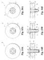
- FIG. 14Ais a top plan view of the FIG. 1 blind bolt fastener inserted through two work pieces.
- FIG. 14Bis a front elevational view, in full section, of the FIG. 14A configuration.
- FIG. 15Ais a top plan view of the FIG. 1 blind bolt fastener partially installed through two work pieces.
- FIG. 15Bis a front elevational view, in full section, of the FIG. 15A configuration.
- FIG. 16Ais a top plan view of the FIG. 1 blind bolt fastener installed fastening two work pieces together.
- FIG. 16Bis a front elevational view, in full section, of the FIG. 16A configuration.
- FIG. 17is a front elevational view, in full section, of an alternate embodiment of a blind bolt fastener inserted through two work pieces.
- FIG. 18is a front elevational view, in full section, of an alternate embodiment of a blind bolt fastener.
- blind bolt fastenerAs used herein, “above,” “top,” “second end” and “front side” refers to the head side of the blind bolt fastener that includes the head portions of the bolt and sleeve. Similarly, “bottom,” “below,” “first end” and “blind side” refers to the side of the blind bolt fastener that passes through the work pieces and may include the threaded portions of the bolt, the deformable portion of the sleeve and the nut.
- “Wrenching portions” and/or “wrenching surfaces” as used hereininclude any known surface that can be used to engage a manual or automatic tool including a cylindrical surface engagable by a one-way clutch or roller clutch.
- the blind bolt fasteners disclosed hereincan be used in both manual and automatic applications. Use of cylindrical surfaces instead of wrenching flats may make it easier to use blind bolt fasteners with automatic installation robots. Conversely, in manual applications, human operators are adapt at adjusting parts as required to fit geometric wrenches and geometric wrench apparatus are generally less expensive than one-way clutches so other applications lend themselves to the use of conventional wrenching surfaces.
- the wrenching portions illustrated hereinare generally external wrenching portions such as conventional hex-shaped surfaces.
- blind bolt fastener 10is illustrated as including bolt 20 , sleeve 30 , nut 60 and drive nut 80 .
- Blind bolt fastener 10is assembled with bolt 20 extending through drive nut 80 and sleeve 30 and threadingly engaged with nut 60 .
- Sleeve 30 and drive nut 80are positioned between bolt 20 and nut 60 .
- bolt 20is a threaded bolt that generally includes enlarged head 21 , head 22 , wrenching portions 23 , externally-threaded portion 24 , unthreaded portion 25 , break groove 26 and frustoconical bearing portion 28 on head 22 .
- Wrenching portion 23is a conventional hex-shaped configuration.
- Break groove 26is configured to fracture and separate enlarged head 21 from the rest of bolt 20 upon application of a predetermined torque to wrenching portion 23 .
- externally-threaded portion 24includes buttress threads incorporating a steep pressure flank and a shallow non-pressure flank.
- externally-threaded portion 24has a pressure flank of between approximately 75° and 90° off the axis of bolt 20 with a non-pressure flank of approximately 45°.
- the pitch of the thread of each flankis similar to that used for a 60° thread found on existing thread blind bolts such as MIL-S-8879 and MIL-S-7742.
- Another acceptable thread formis that of a trapezoid thread wherein the pressure and non-pressure flank angles are approximately 75° off the axis of the bolt 20 .
- a trapezoid thread formis easier to form on materials having little ductility, such as certain titanium alloys.
- sleeve 30includes frustoconical head 32 , inner bearing portion 33 , outer bearing portion 34 , a generally cylindrical body having outer surface 35 and defining bore 36 , wrenching cavities 38 , deformable portion 40 , non-deformable portion 42 , annealed portion 44 , shoulder 46 and end wall 48 .
- deformable portion 40is thin walled compared to comparatively thick walled non-deformable portion 42 .
- Wrenching cavities 38are illustrated in a generally cruciform configuration.
- nut 60is a generally cylindrical body defining internally-threaded bore 62 , ridge 64 , thin walled portion 66 , thick walled portion 68 and end wall 69 .
- Ridge 64is sloped at angle ⁇ , which in the illustrated embodiment is approximately 100°.
- drive nut 80includes wrenching portion 82 , bore 84 and protrusions 88 .
- Protrusions 88are illustrated in a generally cruciform configuration matching wrenching cavities 38 .
- Each protrusion 88has an exposed inclined edge.
- Wrenching portion 82is a conventional hex-shaped configuration.
- blind bolt fastener 10is assembled with core bolt 20 extending into bore 36 and bore 84 with externally-threaded portion 24 threadingly engaged with inner threaded bore 62 with end wall 48 abutting ridge 64 .
- Blind bolt fastener 10is assembled with a slight pretension such that nut 60 and sleeve 30 are substantially rotationally constrained together at the interface between end wall 48 and ridge 64 .
- sleeve 30 and nut 60may be rotationally constrained together using various methods known in the art including using knurled or other friction enhancers and/or mechanical interlocks therebetween to reduce relative rotation between sleeve 30 and nut 60 .
- thin walled deformable portion 40covers thin wall portion 66 .
- the contact area between thin walled deformable portions 40 and 66may also aid nut 60 and sleeve 30 being substantially rotationally constrained together.
- friction enhancers or mechanical interlockscan also be used between thin wall portions 40 and 66 .
- Protrusions 88are matched with wrenching cavities 38 so that drive nut 80 and sleeve 30 are rotationally constrained together when assembled.
- protrusions 88 and wrenching cavities 38are in a generally cruciform configuration with shallow recesses to fit the countersunk configuration of head 32 .
- other embodimentsmay utilize other configurations for wrenching cavities 38 and protrusions 88 , including configurations having a different number, spacing and shape of cavities and protrusions, as appropriate.
- drive nut 80is constrained between head 32 and enlarged head 21 so that protrusions 88 cannot readily cam out of wrenching cavities 38 so long as enlarged head 21 is attached to bolt 20 .
- sleeve 30is manufactured from a material that exhibits a controllable allotropism.
- materialsuch as A-286 corrosion and heat resistance steel (CRES).
- CRESA-286 corrosion and heat resistance steel
- A-286 steelcan be heat treated in a conventional manner to harden sleeve 30 .
- Annealed portion 44may then be selectively annealed to produce a hardness gradient that increases both above and below annealed portion 44 .
- induction heatingcan be used to selectively heat and anneal annealed portion 44 .
- the size and depth of induction heatingcan be controlled through choice of induction-frequency, power-density and time.
- sleeve 30having a high hardness and a high shear strength with annealed portion 44 having a lower hardness and exhibiting greater ductility.
- nut 60may be hardened to a higher hardness than sleeve 30 .
- sleeve 30is fabricated in a conventional manner on a four- or five-die progressive header to produce the shape illustrated in FIGS. 4-6 .
- end wall 48may be machined to square-up the face of end wall 48 to minimize incidents of nut 60 entering sleeve 30 during installation.
- Ridge 64is sloped at angle ⁇ , which in the illustrated embodiment is approximately 100°. In other embodiments, angle ⁇ can be between 90 and 120 degrees. In alternative embodiments, end wall 48 can be beveled to mate with the inclination of ridge 64 .
- blind bolt fastener 10is normally utilized for a range of total thickness of work pieces 90 and 96 (as illustrated in FIGS. 14A-16B ) that extends from a minimum to a maximum total work piece thickness.
- the range between minimum and maximum thicknessmay be 1/16 th of an inch (approximately 1.6 mm). Accordingly, the degree to which portion 44 is annealed and the precise location of annealed portion 44 is determined to provide an appropriately sized bulbed head 45 (as discussed below) over the desired thickness range.
- installation of blind bolt fastener 10is terminated upon application of a pre-determined torque by break groove 26 automatically separating enlarged head 21 from the rest of bolt 20 .
- the pre-determined torqueis set greater than the torque load required to form bulbed head 45 and abut end wall 69 against shoulder 46 .
- Other embodimentscould terminate installation by controlling torque of applied bolt 20 such as through the use of a torque wrench or a torque limited wrench.
- blind bolt fastener 10is illustrated inserted through aligned apertures 91 and 97 of work pieces 90 and 96 with outer bearing portion 34 located in and bearing against counter bore 92 .
- blind bolt fastener 10 ′is illustrated, showing blind bolt fastener 10 in a partially installed condition through work pieces 90 and 96 .
- FIGS. 15A-Billustrates nut 60 advanced up bolt 20 such that sleeve 60 has deformed forming bolt head 45 with end wall 69 abutting shoulder 46 as described above with bulbed head 45 bearing against blind side 98 .
- blind bolt fastener 10 ′′is illustrated, showing blind bolt fastener 10 in an installed configuration with break groove 26 fractured and enlarged head 21 and drive nut 80 removed.
- the installed configuration of the illustrated embodimentpositions unthreaded portion 25 and hardened, non-deformable portion 42 in the shear plane between work pieces 90 and 96 when the fastener is installed (the shear plane being defined in the illustrated embodiments as the interface between work pieces 90 and 96 ).
- blind bolt fastener 10is installed by inserting blind bolt fastener 10 through aligned apertures such as apertures 91 and 97 in work pieces 90 and 96 as illustrated in FIGS. 14A-B .
- Sleeve 30is then restrained by engaging wrenching portion 82 on drive nut 80 .
- Core bolt 20is then tightened by engaging wrenching portion 23 and tightening bolt 20 to advance nut 60 towards sleeve 30 .
- This results in a columnar load on sleeve 30causing it to bulb outwardly at its weakest unrestrained point to form bulbed head 45 . With a properly configured fastener, this should occur at blind side 98 of work piece 96 to clamp work pieces 90 and 96 together.
- Aperture 97constrains sleeve 30 from bulbing outwardly above blind side 98 , forcing bulbed head 45 to form outside of blind side 98 and to clamp work pieces 90 and 96 together.
- Continued tightening of bolt 20eventually increases the clamping force on work pieces 90 and 96 until end wall 69 abuts shoulder 46 , blocking nut 60 from advancing any further up bolt 20 .
- Further tightening of bolt 20increases torsional load on bolt 20 until the torsional strength of break groove 26 is exceeded, which fractures enlarged head 21 off of the remaining portions of bolt 20 and thereby permits the removal of drive nut 80 and enlarged head 21 from the installed assembly as illustrated in FIGS. 16A-B .
- the installed assemblymaintains the torsional load imparted during installation, thereby maintaining a pre-load clamping force between outer bearing portion 34 and bulbed head 45 .
- blind bolt fastener 110with bolt 120 that includes head 122 with wrenching portion 123 and break groove 126 .
- Blind bolt fastener 110requires the use of an external installation tool with protrusions to engage wrenching cavities 38 on sleeve 30 in lieu of drive nut 80 .
- the sleevecould include external wrenching surfaces, i.e. a conventional hex shaped bolt head, instead of internal wrenching cavities.
- blind bolt fastener 210comprising bolt 220 and sleeve 230 .
- Bolt 220includes groove 229 and sleeve 230 includes protuberance 239 .
- Groove 229 and protuberance 239form a sleeve-to-bolt lock that prevents bolt 220 from disengaging from sleeve 230 .
- the illustrated embodimentmay be formed by cold forming sleeve 230 with bolt 220 inserted therein to work material from sleeve 230 into groove 229 thereby creating protuberance 239 . While not illustrated, groove 229 and protuberance 239 can be incorporated in any other embodiment.
Landscapes
- Engineering & Computer Science (AREA)
- General Engineering & Computer Science (AREA)
- Mechanical Engineering (AREA)
- Dowels (AREA)
Abstract
Description
Claims (22)
Priority Applications (1)
| Application Number | Priority Date | Filing Date | Title |
|---|---|---|---|
| US13/245,944US8888425B2 (en) | 2009-03-27 | 2011-09-27 | Blind fastener |
Applications Claiming Priority (3)
| Application Number | Priority Date | Filing Date | Title |
|---|---|---|---|
| US16414109P | 2009-03-27 | 2009-03-27 | |
| PCT/US2010/028832WO2010111593A2 (en) | 2009-03-27 | 2010-03-26 | Blind bolt fastener |
| US13/245,944US8888425B2 (en) | 2009-03-27 | 2011-09-27 | Blind fastener |
Related Parent Applications (1)
| Application Number | Title | Priority Date | Filing Date |
|---|---|---|---|
| PCT/US2010/028832ContinuationWO2010111593A2 (en) | 2009-03-27 | 2010-03-26 | Blind bolt fastener |
Publications (2)
| Publication Number | Publication Date |
|---|---|
| US20120011702A1 US20120011702A1 (en) | 2012-01-19 |
| US8888425B2true US8888425B2 (en) | 2014-11-18 |
Family
ID=42781908
Family Applications (1)
| Application Number | Title | Priority Date | Filing Date |
|---|---|---|---|
| US13/245,944Expired - Fee RelatedUS8888425B2 (en) | 2009-03-27 | 2011-09-27 | Blind fastener |
Country Status (2)
| Country | Link |
|---|---|
| US (1) | US8888425B2 (en) |
| WO (1) | WO2010111593A2 (en) |
Cited By (12)
| Publication number | Priority date | Publication date | Assignee | Title |
|---|---|---|---|---|
| US20140047699A1 (en)* | 2012-04-04 | 2014-02-20 | John D. Pratt | Fastener and Method of Installing Same |
| US10294976B2 (en) | 2012-11-11 | 2019-05-21 | The Boeing Company | Method of installing a structural blind fastener |
| USD909857S1 (en)* | 2019-08-27 | 2021-02-09 | Sps Technologies, Llc | Blind fastener bolt head |
| USD909856S1 (en)* | 2019-08-27 | 2021-02-09 | Sps Technologies, Llc | Blind fastener bolt |
| USD920774S1 (en)* | 2019-08-27 | 2021-06-01 | Sps Technologies, Llc | Blind fastener |
| USD924045S1 (en)* | 2019-10-22 | 2021-07-06 | Domido Limited | Connecting metal nut |
| US11072412B2 (en)* | 2014-05-28 | 2021-07-27 | The Boeing Company | Mounting member with anti-rotation bushings |
| USD935877S1 (en)* | 2019-08-27 | 2021-11-16 | Sps Technologies, Llc | Blind fastener nut |
| US20230243374A1 (en)* | 2020-10-19 | 2023-08-03 | Häfele Berlin Gmbh & Co Kg | Doubling-up fitting and associated assembly having two doubled-up plates |
| US11867212B2 (en)* | 2014-10-13 | 2024-01-09 | Monogram Aerospace Fasterners, Inc. | Deformable sleeve nut and a method of manufacturing |
| US20240141941A1 (en)* | 2022-11-01 | 2024-05-02 | Vive Health LLC | Toilet seat rivet systems |
| EP4011558B1 (en) | 2020-12-08 | 2024-10-09 | The Boeing Company | Method and tool for installing a fastener |
Families Citing this family (14)
| Publication number | Priority date | Publication date | Assignee | Title |
|---|---|---|---|---|
| US9032602B2 (en)* | 2011-07-15 | 2015-05-19 | The Boeing Company | Methods and systems for in-process quality control during drill-fill assembly |
| SE536039C2 (en)* | 2011-08-31 | 2013-04-09 | Lkab Mek Ab | Apparatus for attaching wear means and systems comprising such a device |
| FR2990366B1 (en)* | 2012-05-09 | 2014-04-25 | Bollhoff Otalu Sa | METHOD FOR MANUFACTURING A CRIMPING ASSEMBLY ATTACHMENT TO A SUPPORT AND AN ASSEMBLY ACCESSORY |
| FR2998101B1 (en) | 2012-11-12 | 2014-11-14 | Dubuis Et Cie | DEVICE FOR FIXING AN ELECTRICAL CONNECTING PITCH ON A SUPPORT |
| DE202013011706U1 (en)* | 2013-03-06 | 2014-03-25 | Norma Germany Gmbh | Clamp screw connection, in particular for a clamp, and clamp |
| US20160179924A1 (en)* | 2014-12-23 | 2016-06-23 | International Business Machines Corporation | Persona based content modification |
| CN105508371B (en)* | 2016-02-18 | 2018-02-06 | 航天精工股份有限公司 | A kind of controllable threaded self-plugging rivet with bushing |
| EP3418589A1 (en)* | 2017-06-22 | 2018-12-26 | Metso Sweden Ab | Method and fastening device for fastening a lining element |
| US20190162222A1 (en)* | 2017-11-27 | 2019-05-30 | Sps Technologies, Llc | Blind fastener with frangible nut |
| USD913782S1 (en)* | 2019-06-07 | 2021-03-23 | Sps Technologies, Llc | Blind fastener sleeve |
| CN111963541B (en)* | 2020-08-19 | 2022-04-01 | 中国航空工业集团公司沈阳飞机设计研究所 | Aircraft structure coupling assembling |
| DE102021004482A1 (en) | 2021-09-03 | 2023-03-09 | LANIOL GmbH | head screw |
| US20230083921A1 (en)* | 2021-09-10 | 2023-03-16 | The Boeing Company | Blind fasteners and associated methods for installing blind fasteners |
| US12292065B2 (en) | 2022-02-11 | 2025-05-06 | The Boeing Company | Structural blind sleeves and associated systems and methods for clamping a first structure relative to a second structure to yield a clamped-up structure |
Citations (42)
| Publication number | Priority date | Publication date | Assignee | Title |
|---|---|---|---|---|
| US2282711A (en) | 1940-11-14 | 1942-05-12 | Howard J Eklund | Rivet |
| US2508409A (en) | 1948-03-18 | 1950-05-23 | Eloise T Roe | Locking, threading assembly |
| US2763314A (en) | 1952-11-29 | 1956-09-18 | Goodrich Co B F | Expansible hollow threaded rivet having a buttress porting to provide for increased resistance to shear |
| US2863351A (en) | 1956-02-20 | 1958-12-09 | Rudolph M Vaughn | Expanding fastener having threads of opposite hand to maintain the parts in engagement |
| US2971425A (en) | 1956-12-31 | 1961-02-14 | Richard H Blakeley | Blind fastener having an expandable nut drawn into endwise abutment with work surface |
| US3058386A (en) | 1957-09-25 | 1962-10-16 | Earle L Morrow | Binding device with contracting segments having radius smaller than rod engaged thereby |
| US3236143A (en) | 1959-05-15 | 1966-02-22 | Hi Shear Corp | Blind fastening device with collapsible tube |
| US3253495A (en) | 1962-12-06 | 1966-05-31 | Huck Mfg Co | Hardened blind bolt with annealed shank portion |
| US3283640A (en) | 1964-06-20 | 1966-11-08 | Ono Teizo | Anchor bolt |
| US3322449A (en) | 1964-06-18 | 1967-05-30 | Vsi Corp | Blind fastener system |
| US3345900A (en) | 1964-10-15 | 1967-10-10 | Standard Pressed Steel Co | Blind fastener |
| US3461771A (en) | 1967-08-07 | 1969-08-19 | Franklin S Briles | Blind fastener |
| US4015505A (en) | 1976-02-23 | 1977-04-05 | Illinois Tool Works Inc. | One sided fastener device |
| US4237768A (en) | 1976-11-05 | 1980-12-09 | Hi-Shear Corporation | Blind fastener |
| US4364697A (en) | 1977-12-12 | 1982-12-21 | Sps Technologies, Inc. | Blind fastener assembly |
| US4501515A (en) | 1982-06-25 | 1985-02-26 | Scott Investment Partners | Dynamic rock stabilizing fixture |
| US4772167A (en) | 1986-05-07 | 1988-09-20 | Monogram Industries, Inc. | Blind fastener with deformable drive nut |
| US4900205A (en) | 1988-08-15 | 1990-02-13 | Huck Manufacturing Co. | Blind fastener forming a blind head with a large effective area |
| US4919576A (en)* | 1984-09-04 | 1990-04-24 | Allfast Fastening Systems, Inc. | Locking apparatus for blind fasteners |
| US4929134A (en) | 1987-09-22 | 1990-05-29 | Hilti Aktiengesellschaft | Expansion dowel assembly |
| US4950115A (en) | 1989-10-02 | 1990-08-21 | Huck Manufacturing Company | Blind fastener with expandable sleeve forming a blind bulbed head with large bearing area and a pin having a controlled protrusion length |
| US4967463A (en)* | 1984-02-23 | 1990-11-06 | Mag Aerospace Industries, Inc. | Method of fastening panels using drive nut blind fasteners |
| US4973210A (en) | 1988-08-20 | 1990-11-27 | Emhart Industries, Inc. | Anchors for fixing to dense concrete, masonry and the like |
| US4984945A (en) | 1987-09-22 | 1991-01-15 | Hilti Aktiengesellschaft | Expansion dowel assembly |
| US4988247A (en) | 1989-05-16 | 1991-01-29 | Summerlin Frederick A | Blind rivet and method of making same |
| US5046348A (en) | 1989-10-05 | 1991-09-10 | Textron, Inc. | Blind fastener for composite materials |
| US5051048A (en) | 1987-08-31 | 1991-09-24 | The B. F. Goodrich Company | Blind fastener |
| US5152648A (en) | 1991-11-06 | 1992-10-06 | Textron Inc. | Blind fastener for composite materials |
| US5263803A (en) | 1992-05-13 | 1993-11-23 | Emhart Inc. | Anchor bolt |
| US5498110A (en) | 1994-02-25 | 1996-03-12 | Monogram Aerospace Fasteners | Blind fastener with deformable sleeve |
| US5569005A (en) | 1994-01-18 | 1996-10-29 | Emhart Inc. | Two-part deformable fastener |
| US5759001A (en) | 1995-09-23 | 1998-06-02 | Emhart Inc. | Blind rivet |
| US5816761A (en) | 1996-01-11 | 1998-10-06 | The Boeing Company | Lightweight structural blind fastener |
| US5947667A (en) | 1995-11-07 | 1999-09-07 | The Boeing Company | Structural blind fastener |
| US6021617A (en) | 1993-03-08 | 2000-02-08 | Sheahan; James P. | Leak localizing using a combination of penetrating devices and barriers |
| US6062783A (en) | 1997-12-31 | 2000-05-16 | Jaguar Cars, Limited | Expanding bush and captive bolt assembly |
| US6224309B1 (en)* | 1999-04-08 | 2001-05-01 | Fairchild Holding Corp. | Structural blind fastener |
| US20040022596A1 (en) | 2002-07-30 | 2004-02-05 | Belanger Joseph D. | Fastener having integral drive nut |
| US20040033119A1 (en) | 2002-08-13 | 2004-02-19 | Gerhart Hufnagl | Blind fastener and drive nut assembly and method of installation thereof |
| US6868757B2 (en) | 2003-05-20 | 2005-03-22 | Huck International, Inc. | Blind fastener and nose assembly for installation of the blind fastener |
| US20050123372A1 (en) | 2002-02-08 | 2005-06-09 | Yoshinori Sato | Fastener |
| US20070243035A1 (en) | 2006-02-28 | 2007-10-18 | Pratt John D | Mechanically locked blind bolt fastener |
- 2010
- 2010-03-26WOPCT/US2010/028832patent/WO2010111593A2/enactiveApplication Filing
- 2011
- 2011-09-27USUS13/245,944patent/US8888425B2/ennot_activeExpired - Fee Related
Patent Citations (45)
| Publication number | Priority date | Publication date | Assignee | Title |
|---|---|---|---|---|
| US2282711A (en) | 1940-11-14 | 1942-05-12 | Howard J Eklund | Rivet |
| US2508409A (en) | 1948-03-18 | 1950-05-23 | Eloise T Roe | Locking, threading assembly |
| US2763314A (en) | 1952-11-29 | 1956-09-18 | Goodrich Co B F | Expansible hollow threaded rivet having a buttress porting to provide for increased resistance to shear |
| US2863351A (en) | 1956-02-20 | 1958-12-09 | Rudolph M Vaughn | Expanding fastener having threads of opposite hand to maintain the parts in engagement |
| US2971425A (en) | 1956-12-31 | 1961-02-14 | Richard H Blakeley | Blind fastener having an expandable nut drawn into endwise abutment with work surface |
| US3058386A (en) | 1957-09-25 | 1962-10-16 | Earle L Morrow | Binding device with contracting segments having radius smaller than rod engaged thereby |
| US3236143A (en) | 1959-05-15 | 1966-02-22 | Hi Shear Corp | Blind fastening device with collapsible tube |
| US3253495A (en) | 1962-12-06 | 1966-05-31 | Huck Mfg Co | Hardened blind bolt with annealed shank portion |
| US3322449A (en) | 1964-06-18 | 1967-05-30 | Vsi Corp | Blind fastener system |
| US3283640A (en) | 1964-06-20 | 1966-11-08 | Ono Teizo | Anchor bolt |
| US3345900A (en) | 1964-10-15 | 1967-10-10 | Standard Pressed Steel Co | Blind fastener |
| US3461771A (en) | 1967-08-07 | 1969-08-19 | Franklin S Briles | Blind fastener |
| US4015505A (en) | 1976-02-23 | 1977-04-05 | Illinois Tool Works Inc. | One sided fastener device |
| US4237768A (en) | 1976-11-05 | 1980-12-09 | Hi-Shear Corporation | Blind fastener |
| US4364697A (en) | 1977-12-12 | 1982-12-21 | Sps Technologies, Inc. | Blind fastener assembly |
| US4501515A (en) | 1982-06-25 | 1985-02-26 | Scott Investment Partners | Dynamic rock stabilizing fixture |
| US4967463A (en)* | 1984-02-23 | 1990-11-06 | Mag Aerospace Industries, Inc. | Method of fastening panels using drive nut blind fasteners |
| US4919576A (en)* | 1984-09-04 | 1990-04-24 | Allfast Fastening Systems, Inc. | Locking apparatus for blind fasteners |
| US4772167A (en) | 1986-05-07 | 1988-09-20 | Monogram Industries, Inc. | Blind fastener with deformable drive nut |
| US5051048A (en) | 1987-08-31 | 1991-09-24 | The B. F. Goodrich Company | Blind fastener |
| US4929134A (en) | 1987-09-22 | 1990-05-29 | Hilti Aktiengesellschaft | Expansion dowel assembly |
| US4984945A (en) | 1987-09-22 | 1991-01-15 | Hilti Aktiengesellschaft | Expansion dowel assembly |
| US4900205A (en) | 1988-08-15 | 1990-02-13 | Huck Manufacturing Co. | Blind fastener forming a blind head with a large effective area |
| US4973210A (en) | 1988-08-20 | 1990-11-27 | Emhart Industries, Inc. | Anchors for fixing to dense concrete, masonry and the like |
| US4988247A (en) | 1989-05-16 | 1991-01-29 | Summerlin Frederick A | Blind rivet and method of making same |
| US4950115A (en) | 1989-10-02 | 1990-08-21 | Huck Manufacturing Company | Blind fastener with expandable sleeve forming a blind bulbed head with large bearing area and a pin having a controlled protrusion length |
| US5046348A (en) | 1989-10-05 | 1991-09-10 | Textron, Inc. | Blind fastener for composite materials |
| US5152648A (en) | 1991-11-06 | 1992-10-06 | Textron Inc. | Blind fastener for composite materials |
| US5263803A (en) | 1992-05-13 | 1993-11-23 | Emhart Inc. | Anchor bolt |
| US6021617A (en) | 1993-03-08 | 2000-02-08 | Sheahan; James P. | Leak localizing using a combination of penetrating devices and barriers |
| US5569005A (en) | 1994-01-18 | 1996-10-29 | Emhart Inc. | Two-part deformable fastener |
| US5498110A (en) | 1994-02-25 | 1996-03-12 | Monogram Aerospace Fasteners | Blind fastener with deformable sleeve |
| US5634751A (en) | 1994-02-25 | 1997-06-03 | Monogram Aerospace Fasteners | Blind fastener with deformable sleeve |
| US5759001A (en) | 1995-09-23 | 1998-06-02 | Emhart Inc. | Blind rivet |
| US5947667A (en) | 1995-11-07 | 1999-09-07 | The Boeing Company | Structural blind fastener |
| US5816761A (en) | 1996-01-11 | 1998-10-06 | The Boeing Company | Lightweight structural blind fastener |
| US6062783A (en) | 1997-12-31 | 2000-05-16 | Jaguar Cars, Limited | Expanding bush and captive bolt assembly |
| US6224309B1 (en)* | 1999-04-08 | 2001-05-01 | Fairchild Holding Corp. | Structural blind fastener |
| US20050123372A1 (en) | 2002-02-08 | 2005-06-09 | Yoshinori Sato | Fastener |
| US20040022596A1 (en) | 2002-07-30 | 2004-02-05 | Belanger Joseph D. | Fastener having integral drive nut |
| US20040033119A1 (en) | 2002-08-13 | 2004-02-19 | Gerhart Hufnagl | Blind fastener and drive nut assembly and method of installation thereof |
| US7033120B2 (en)* | 2002-08-13 | 2006-04-25 | Huck International, Inc. | Blind fastener and drive nut assembly and method of installation thereof |
| US6868757B2 (en) | 2003-05-20 | 2005-03-22 | Huck International, Inc. | Blind fastener and nose assembly for installation of the blind fastener |
| US20070243035A1 (en) | 2006-02-28 | 2007-10-18 | Pratt John D | Mechanically locked blind bolt fastener |
| US7857563B2 (en)* | 2006-02-28 | 2010-12-28 | Monogram Aerospace Fasteners, Inc. | Mechanically locked blind bolt fastener |
Non-Patent Citations (2)
| Title |
|---|
| Korean Intellectual Property Office; International Search Report dated Oct. 22, 2010 in related PCT Application No. PCT/US2010/028832. |
| Korean Intellectual Property Office; Written Opinion dated Oct. 22, 2010 received in related PCT Application No. PCT/US2010/028832. |
Cited By (13)
| Publication number | Priority date | Publication date | Assignee | Title |
|---|---|---|---|---|
| US9284971B2 (en)* | 2012-04-04 | 2016-03-15 | John D. Pratt | Fastener and method of installing same |
| US20140047699A1 (en)* | 2012-04-04 | 2014-02-20 | John D. Pratt | Fastener and Method of Installing Same |
| US10294976B2 (en) | 2012-11-11 | 2019-05-21 | The Boeing Company | Method of installing a structural blind fastener |
| US11072412B2 (en)* | 2014-05-28 | 2021-07-27 | The Boeing Company | Mounting member with anti-rotation bushings |
| US11867212B2 (en)* | 2014-10-13 | 2024-01-09 | Monogram Aerospace Fasterners, Inc. | Deformable sleeve nut and a method of manufacturing |
| USD909857S1 (en)* | 2019-08-27 | 2021-02-09 | Sps Technologies, Llc | Blind fastener bolt head |
| USD909856S1 (en)* | 2019-08-27 | 2021-02-09 | Sps Technologies, Llc | Blind fastener bolt |
| USD920774S1 (en)* | 2019-08-27 | 2021-06-01 | Sps Technologies, Llc | Blind fastener |
| USD935877S1 (en)* | 2019-08-27 | 2021-11-16 | Sps Technologies, Llc | Blind fastener nut |
| USD924045S1 (en)* | 2019-10-22 | 2021-07-06 | Domido Limited | Connecting metal nut |
| US20230243374A1 (en)* | 2020-10-19 | 2023-08-03 | Häfele Berlin Gmbh & Co Kg | Doubling-up fitting and associated assembly having two doubled-up plates |
| EP4011558B1 (en) | 2020-12-08 | 2024-10-09 | The Boeing Company | Method and tool for installing a fastener |
| US20240141941A1 (en)* | 2022-11-01 | 2024-05-02 | Vive Health LLC | Toilet seat rivet systems |
Also Published As
| Publication number | Publication date |
|---|---|
| US20120011702A1 (en) | 2012-01-19 |
| WO2010111593A3 (en) | 2011-01-13 |
| WO2010111593A2 (en) | 2010-09-30 |
Similar Documents
| Publication | Publication Date | Title |
|---|---|---|
| US8888425B2 (en) | Blind fastener | |
| US8348566B2 (en) | Blind fastener | |
| US8517649B2 (en) | Dual-action disposable clamp | |
| US7857563B2 (en) | Mechanically locked blind bolt fastener | |
| EP1635994B1 (en) | Blind fastener and nose assembly for installation of the blind fastener | |
| US8398345B2 (en) | Low profile dual-action disposable clamp | |
| JP4796278B2 (en) | Expandable collet anchor device, its components and methods for making and using the same | |
| US9284971B2 (en) | Fastener and method of installing same | |
| US11585364B2 (en) | Blind fastener | |
| US20070243037A1 (en) | Blind bolt fastener | |
| US20090053006A1 (en) | Blind fastener and nose assembly for installation thereof | |
| US20140037398A1 (en) | Blind rivet bolt | |
| US20180238372A1 (en) | Attachment fitted on a single side | |
| US9903403B2 (en) | Fastener and method of installing same | |
| EP2454493B1 (en) | Low profile dual-action disposable clamp | |
| TW202447094A (en) | Improved rivet nut | |
| US3285119A (en) | Torque-limiting fastener | |
| GB2146724A (en) | Torque-limited screw-thread locking fastener | |
| RU2762174C2 (en) | Tool for tightening torque control and combination of tool for tightening torque control and fastener | |
| US20190032695A1 (en) | Internal positive stop, break-off flushness in blind fasteners |
Legal Events
| Date | Code | Title | Description |
|---|---|---|---|
| AS | Assignment | Owner name:MONOGRAM AEROSPACE FASTENERS, INC., CALIFORNIA Free format text:ASSIGNMENT OF ASSIGNORS INTEREST;ASSIGNOR:PRATT, JOHN D.;REEL/FRAME:026996/0616 Effective date:20090406 | |
| AS | Assignment | Owner name:TRIMAS CORPORATION, MICHIGAN Free format text:RELEASE OF SECURITY INTEREST;ASSIGNOR:THE BANK OF NEW YORK MELLON TRUST COMPANY, N.A.;REEL/FRAME:029291/0265 Effective date:20121107 | |
| AS | Assignment | Owner name:JPMORGAN CHASE BANK, N.A., AS COLLATERAL AGENT, TE Free format text:PATENT SECURITY AGREEMENT;ASSIGNORS:TRIMAS CORPORATION (SUCCESSOR TO MASCOTECH, INC.);TRIMAS COMPANY LLC;ARMINAK & ASSOCIATES LLC;AND OTHERS;REEL/FRAME:029537/0582 Effective date:20121011 | |
| AS | Assignment | Owner name:TRIMAS COMPANY LLC, MICHIGAN Free format text:RELEASE OF REEL/FRAME 029537/0582;ASSIGNOR:JPMORGAN CHASE BANK, N.A.;REEL/FRAME:031645/0436 Effective date:20131016 Owner name:NI INDUSTRIES, INC., ILLINOIS Free format text:RELEASE OF REEL/FRAME 029537/0582;ASSIGNOR:JPMORGAN CHASE BANK, N.A.;REEL/FRAME:031645/0436 Effective date:20131016 Owner name:LAMONS GASKET COMPANY, TEXAS Free format text:RELEASE OF REEL/FRAME 029537/0582;ASSIGNOR:JPMORGAN CHASE BANK, N.A.;REEL/FRAME:031645/0436 Effective date:20131016 Owner name:ARROW ENGINE COMPANY, OKLAHOMA Free format text:RELEASE OF REEL/FRAME 029537/0582;ASSIGNOR:JPMORGAN CHASE BANK, N.A.;REEL/FRAME:031645/0436 Effective date:20131016 Owner name:CEQUENT CONSUMER PRODUCTS, INC., OHIO Free format text:RELEASE OF REEL/FRAME 029537/0582;ASSIGNOR:JPMORGAN CHASE BANK, N.A.;REEL/FRAME:031645/0436 Effective date:20131016 Owner name:TRIMAS CORPORATION (SUCCESSOR TO MASCO TECH, INC.) Free format text:RELEASE OF REEL/FRAME 029537/0582;ASSIGNOR:JPMORGAN CHASE BANK, N.A.;REEL/FRAME:031645/0436 Effective date:20131016 Owner name:COMPAC CORPORATION, NEW JERSEY Free format text:RELEASE OF REEL/FRAME 029537/0582;ASSIGNOR:JPMORGAN CHASE BANK, N.A.;REEL/FRAME:031645/0436 Effective date:20131016 Owner name:INNOVATIVE MOLDING, CALIFORNIA Free format text:RELEASE OF REEL/FRAME 029537/0582;ASSIGNOR:JPMORGAN CHASE BANK, N.A.;REEL/FRAME:031645/0436 Effective date:20131016 Owner name:NORRIS CYLINDER COMPANY, TEXAS Free format text:RELEASE OF REEL/FRAME 029537/0582;ASSIGNOR:JPMORGAN CHASE BANK, N.A.;REEL/FRAME:031645/0436 Effective date:20131016 Owner name:CEQUENT PERFORMANCE PRODUCTS, INC. (SUCCESSOR TO C Free format text:RELEASE OF REEL/FRAME 029537/0582;ASSIGNOR:JPMORGAN CHASE BANK, N.A.;REEL/FRAME:031645/0436 Effective date:20131016 Owner name:ARMINAK & ASSOCIATES LLC, CALIFORNIA Free format text:RELEASE OF REEL/FRAME 029537/0582;ASSIGNOR:JPMORGAN CHASE BANK, N.A.;REEL/FRAME:031645/0436 Effective date:20131016 Owner name:RIEKE-ARMINAK CORP., MICHIGAN Free format text:RELEASE OF REEL/FRAME 029537/0582;ASSIGNOR:JPMORGAN CHASE BANK, N.A.;REEL/FRAME:031645/0436 Effective date:20131016 Owner name:RIEKE CORPORATION, INDIANA Free format text:RELEASE OF REEL/FRAME 029537/0582;ASSIGNOR:JPMORGAN CHASE BANK, N.A.;REEL/FRAME:031645/0436 Effective date:20131016 Owner name:TRIMAS INTERNATIONAL HOLDINGS LLC, MICHIGAN Free format text:RELEASE OF REEL/FRAME 029537/0582;ASSIGNOR:JPMORGAN CHASE BANK, N.A.;REEL/FRAME:031645/0436 Effective date:20131016 Owner name:MONOGRAM AEROSPACE FASTENERS, INC., CALIFORNIA Free format text:RELEASE OF REEL/FRAME 029537/0582;ASSIGNOR:JPMORGAN CHASE BANK, N.A.;REEL/FRAME:031645/0436 Effective date:20131016 Owner name:RIEKE LEASING CO., INCORPORATED, INDIANA Free format text:RELEASE OF REEL/FRAME 029537/0582;ASSIGNOR:JPMORGAN CHASE BANK, N.A.;REEL/FRAME:031645/0436 Effective date:20131016 | |
| AS | Assignment | Owner name:PRATT, JOHN D., CALIFORNIA Free format text:ASSIGNMENT OF ASSIGNORS INTEREST;ASSIGNOR:MONOGRAM AEROSPACE FASTENERS, INC.;REEL/FRAME:035951/0714 Effective date:20150608 | |
| FEPP | Fee payment procedure | Free format text:MAINTENANCE FEE REMINDER MAILED (ORIGINAL EVENT CODE: REM.) | |
| LAPS | Lapse for failure to pay maintenance fees | Free format text:PATENT EXPIRED FOR FAILURE TO PAY MAINTENANCE FEES (ORIGINAL EVENT CODE: EXP.); ENTITY STATUS OF PATENT OWNER: LARGE ENTITY | |
| STCH | Information on status: patent discontinuation | Free format text:PATENT EXPIRED DUE TO NONPAYMENT OF MAINTENANCE FEES UNDER 37 CFR 1.362 | |
| FP | Lapsed due to failure to pay maintenance fee | Effective date:20181118 |