US8888336B2 - Air deflectors for heat management in a lighting module - Google Patents
Air deflectors for heat management in a lighting moduleDownload PDFInfo
- Publication number
- US8888336B2 US8888336B2US13/408,973US201213408973AUS8888336B2US 8888336 B2US8888336 B2US 8888336B2US 201213408973 AUS201213408973 AUS 201213408973AUS 8888336 B2US8888336 B2US 8888336B2
- Authority
- US
- United States
- Prior art keywords
- housing
- lighting module
- heat
- light
- deflector
- Prior art date
- Legal status (The legal status is an assumption and is not a legal conclusion. Google has not performed a legal analysis and makes no representation as to the accuracy of the status listed.)
- Active, expires
Links
Images


Classifications
- F—MECHANICAL ENGINEERING; LIGHTING; HEATING; WEAPONS; BLASTING
- F21—LIGHTING
- F21V—FUNCTIONAL FEATURES OR DETAILS OF LIGHTING DEVICES OR SYSTEMS THEREOF; STRUCTURAL COMBINATIONS OF LIGHTING DEVICES WITH OTHER ARTICLES, NOT OTHERWISE PROVIDED FOR
- F21V29/00—Protecting lighting devices from thermal damage; Cooling or heating arrangements specially adapted for lighting devices or systems
- F21V29/50—Cooling arrangements
- F21V29/70—Cooling arrangements characterised by passive heat-dissipating elements, e.g. heat-sinks
- B—PERFORMING OPERATIONS; TRANSPORTING
- B01—PHYSICAL OR CHEMICAL PROCESSES OR APPARATUS IN GENERAL
- B01J—CHEMICAL OR PHYSICAL PROCESSES, e.g. CATALYSIS OR COLLOID CHEMISTRY; THEIR RELEVANT APPARATUS
- B01J19/00—Chemical, physical or physico-chemical processes in general; Their relevant apparatus
- B01J19/08—Processes employing the direct application of electric or wave energy, or particle radiation; Apparatus therefor
- B01J19/12—Processes employing the direct application of electric or wave energy, or particle radiation; Apparatus therefor employing electromagnetic waves
- B01J19/122—Incoherent waves
- B01J19/123—Ultraviolet light
- F—MECHANICAL ENGINEERING; LIGHTING; HEATING; WEAPONS; BLASTING
- F21—LIGHTING
- F21V—FUNCTIONAL FEATURES OR DETAILS OF LIGHTING DEVICES OR SYSTEMS THEREOF; STRUCTURAL COMBINATIONS OF LIGHTING DEVICES WITH OTHER ARTICLES, NOT OTHERWISE PROVIDED FOR
- F21V19/00—Fastening of light sources or lamp holders
- F21V19/001—Fastening of light sources or lamp holders the light sources being semiconductors devices, e.g. LEDs
- F21V19/0015—Fastening arrangements intended to retain light sources
- F21V19/002—Fastening arrangements intended to retain light sources the fastening means engaging the encapsulation or the packaging of the semiconductor device
- F—MECHANICAL ENGINEERING; LIGHTING; HEATING; WEAPONS; BLASTING
- F21—LIGHTING
- F21V—FUNCTIONAL FEATURES OR DETAILS OF LIGHTING DEVICES OR SYSTEMS THEREOF; STRUCTURAL COMBINATIONS OF LIGHTING DEVICES WITH OTHER ARTICLES, NOT OTHERWISE PROVIDED FOR
- F21V29/00—Protecting lighting devices from thermal damage; Cooling or heating arrangements specially adapted for lighting devices or systems
- F21V29/50—Cooling arrangements
- F21V29/70—Cooling arrangements characterised by passive heat-dissipating elements, e.g. heat-sinks
- F21V29/83—Cooling arrangements characterised by passive heat-dissipating elements, e.g. heat-sinks the elements having apertures, ducts or channels, e.g. heat radiation holes
- H—ELECTRICITY
- H05—ELECTRIC TECHNIQUES NOT OTHERWISE PROVIDED FOR
- H05K—PRINTED CIRCUITS; CASINGS OR CONSTRUCTIONAL DETAILS OF ELECTRIC APPARATUS; MANUFACTURE OF ASSEMBLAGES OF ELECTRICAL COMPONENTS
- H05K7/00—Constructional details common to different types of electric apparatus
- H05K7/20—Modifications to facilitate cooling, ventilating, or heating
- H05K7/20009—Modifications to facilitate cooling, ventilating, or heating using a gaseous coolant in electronic enclosures
- H05K7/20136—Forced ventilation, e.g. by fans
- H05K7/20145—Means for directing air flow, e.g. ducts, deflectors, plenum or guides
- F—MECHANICAL ENGINEERING; LIGHTING; HEATING; WEAPONS; BLASTING
- F21—LIGHTING
- F21Y—INDEXING SCHEME ASSOCIATED WITH SUBCLASSES F21K, F21L, F21S and F21V, RELATING TO THE FORM OR THE KIND OF THE LIGHT SOURCES OR OF THE COLOUR OF THE LIGHT EMITTED
- F21Y2105/00—Planar light sources
- F21Y2105/10—Planar light sources comprising a two-dimensional array of point-like light-generating elements
- F—MECHANICAL ENGINEERING; LIGHTING; HEATING; WEAPONS; BLASTING
- F21—LIGHTING
- F21Y—INDEXING SCHEME ASSOCIATED WITH SUBCLASSES F21K, F21L, F21S and F21V, RELATING TO THE FORM OR THE KIND OF THE LIGHT SOURCES OR OF THE COLOUR OF THE LIGHT EMITTED
- F21Y2115/00—Light-generating elements of semiconductor light sources
- F21Y2115/10—Light-emitting diodes [LED]
- Y—GENERAL TAGGING OF NEW TECHNOLOGICAL DEVELOPMENTS; GENERAL TAGGING OF CROSS-SECTIONAL TECHNOLOGIES SPANNING OVER SEVERAL SECTIONS OF THE IPC; TECHNICAL SUBJECTS COVERED BY FORMER USPC CROSS-REFERENCE ART COLLECTIONS [XRACs] AND DIGESTS
- Y10—TECHNICAL SUBJECTS COVERED BY FORMER USPC
- Y10T—TECHNICAL SUBJECTS COVERED BY FORMER US CLASSIFICATION
- Y10T29/00—Metal working
- Y10T29/49—Method of mechanical manufacture
- Y10T29/49826—Assembling or joining
Definitions
- Solid-state light emitterssuch as light emitting diodes (LEDs) and laser diodes, have several advantages over using more traditional arc lamps during curing processes, such as ultraviolet (UV) curing processes.
- Solid-state light emittersgenerally use less power, generate less heat, produce a higher quality cure, and have higher reliability than traditional arc lamps. Some modifications increase the effectiveness and efficiency of the solid-state light emitters even further.
- solid-state light emittersemit less heat than their arc lamp counterparts, the temperatures emitted from the solid-state light emitters are still very high and can cause overheating of the solid-state light emitters during use and damage to the components of the solid-state light emitters over time. Overheating and damage to the components of the solid-state light emitters causes significant amounts of downtime for repair and loss of revenue.
- Some solid-state light emitterstry to incorporate cooling systems to remove some of the heat that is generated when the solid-state light emitter emits light.
- these cooling systemsinclude one or more heat sinks that help remove heat generated by the solid-state light emitters from the housing through openings or other heat exits in the housing, which results in air being expelled from the housing.
- These openings or heat exits in the housingare generally located near the medium on which the curing process occurs and can cause air to be expelled onto the medium, which disturbs or damages the curing process and decreases its accuracy. This results in the curing process needing to be repeated, which increases manufacturing costs and decreases quality and efficiency.
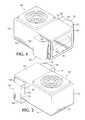
- FIG. 1shows a front perspective view of a lighting module having deflectors.
- FIG. 2shows a back perspective view of the lighting module with the deflectors shown in FIG. 1 .
- FIG. 3shows a top plan view of the air flow pathway that exits the lighting module having the deflectors that is illustrated in FIG. 1 .
- FIG. 4shows a partial exploded view of a deflector and the portion of the lighting module to which it is secured.
- FIGS. 1 and 2show a lighting module 100 having a housing 102 , an array of light-emitting elements 104 , and a pair of heat exits 106 .
- the housing 102is a rectangular, box-shaped structure in this example, although it can be any other suitable size and shape in other configurations.
- the housing 102is a protective structure to house the array of light-emitting elements 104 and may include any suitable protective materials.
- the housing 102 in FIGS. 1 and 2has a front surface 108 , a back surface 110 , two opposing side surfaces 112 , 114 , a top surface 116 , and a bottom surface (not shown).
- the front surface 108includes a window 118 through which the array of light-emitting elements 104 emits light.
- the window 118may be positioned on another suitable surface of the housing 102 in other configurations.
- the window 118 of the lighting module 100is positioned such that the array of light-emitting elements 104 emit light toward a medium with some type of light-curable material.
- the lighting module 100is positioned vertically and a substrate, such as paper or plastic, is positioned below the lighting module 100 , such that the front surface 108 of the lighting module 100 having the window 118 through which the light is emitted faces the substrate.
- the light-curable materialis positioned on the substrate so that the light cures the material when light is emitted through the window 118 .
- the lighting module 100is movable with respect to the medium in some configurations and may be adjustable in any suitable direction to achieve the necessary cure of the light-curing material to the medium.
- the array of light-emitting elements 104may include light-emitting diodes (LEDs). These LEDs may emit light in a range of wavelengths. For example, the LEDs may emit ultraviolet light in the range of wavelengths between 10-400 nanometers.
- the array of light-emitting elements 104generates a substantial amount of heat when it emits light that can damage the lighting module 100 .
- Various heat management systemshave been developed to help control the heat generated during this process, such as including one or more heat sinks 120 in the lighting module 100 .
- the heat sink(s) 120 included in the lighting module 100are often positioned to dissipate the heat generated within the housing 102 so that the heat can be expelled through a heat exit 106 or other type of opening in the housing 102 of the lighting module 100 .
- the heat dissipated by the heat sink(s)are expelled through the heat exits by a fan or other expulsion device.
- the heatis expelled through the heat exits in a passive manner without the use of a fan or any other type of expulsion device.
- Reference to the expulsion of heat from the housing 102 of the lighting module 100includes both the active expulsion of the heat by an expulsion device, such as a fan, and the passive expulsion of heat that does not require any type of assistive device to cause the heat to exit the housing 102 .
- Example heat exits 106 and an example heat sink 120are shown in FIGS. 1 and 2 .
- the heat sink(s) 120dissipate warm or hot air generated within the housing 102 that then exits the housing 102 through the heat exits 106 or openings positioned on the opposing side surfaces 112 , 114 of the housing 102 , as shown in FIGS. 1 and 2 .
- the heat sink(s) 120are spaced apart from or otherwise considered a discrete element from the heat exits 106 .
- the heat sinks 120are integrally formed with the heat exits 106 .
- FIGS. 1 and 2show a portion of a heat sink that is positioned within the openings of the heat exits 106 . In this configuration, warm or hot air is expelled through the heat exits 106 . Without the deflectors 122 shown in FIGS.
- this airis expelled in various directions from the housing 102 , including toward the front surface 108 and the window 118 of the housing 102 and thus toward the medium where the curing occurs.
- airis allowed to be expelled in the direction of the medium where the curing occurs, it often disrupts the curing process.
- the deflectors 122 shown in FIGS. 1 and 2guide the heat that generates the warm or hot air away from the housing 102 in a direction away from the medium upon which the curing occurs. In these examples, the deflectors 122 guide the heat away from the housing 102 in a direction away from the window 118 through which the light is emitted because the medium is positioned adjacent or otherwise near the window 118 .
- the deflectors 122 in FIGS. 1 and 2guide the air away from the housing 102 of the lighting module 100 in a direction that is approximately 180° away from the window 118 , essentially in a direction exactly opposite of the window 118 , as shown by the arrows in FIG. 3 .
- This configurationcauses the least amount of air to disrupt the curing process because the air flow path directs the air in the opposite direction of the window 118 on the front surface 108 of the lighting module 100 and thus away from the medium upon which the curing process occurs.
- the deflectors 122guide the air in a direction that is at an angle that is at least 90° with respect to the window 118 and in other examples the deflectors guide the air in a direction that is at an angle that is at least 120° with respect to the window 118 .
- the deflectors 122are any suitable shape that guides the heat away from the housing 102 of the lighting module 100 .
- the deflectors 122 in FIGS. 1-4have a curved portion 124 at one end that extends over a portion of the heat exit 106 .
- the curved portion 124extends over the entire heat exit 106 or accounts for the entire deflector 122 .
- the contour of the deflector 122may be entirely curved (i.e., the curved portion may comprise the entire deflector), may have multiple different curved portions, or may be some combination of curved and linear portions.
- the deflectors 122have a curved portion 124 and a linear portion 126 .
- the curved portion 124 and a portion of the linear portion 126extend over the heat exit 106 in these examples.
- the linear portion 126extends beyond the heat exit 106 on the side surface 112 of the lighting module 100 .
- the deflector 122extends a distance 128 away from the side surface 112 of the lighting module 100 to permit heat and air to be guided away from the housing 102 .
- the radius of curvature of the curved portion 124affects the angle at which the air or heat is guided away from the housing 102 of the lighting module 100 . As the radius of curvature of the curved portion 124 decreases the angle at which the heat or air is guided away from the housing 102 of the lighting module 100 increases with respect to the window 118 and the medium.
- the lighting module 100includes two heat exits 106 and two corresponding deflectors 122 that extend over their respective heat exits 106 .
- a deflector 122is positioned to extend over every heat exit 106 .
- some heat exitsdo not have a corresponding deflector.
- the heat exitsare positioned anywhere on the housing of the lighting module in any suitable arrangement and on any surface of the housing. The heat exits are arranged to most effectively help the heat sinks expel the heat and air from the housing when the array of light-emitting elements generate heat during use.
- one heat sink 120is positioned within the housing 102 to dissipate heat generated within the housing 102 , which is then expelled during use of the light-emitting elements 104 .
- the housing 102may have two heat exits 106 positioned on either side surface 112 , 114 of the housing 102 to expel heat from the heat sink 120 , as shown in FIGS. 1-3 .
- the heat exits 106are a discrete element from the heat sink 120 and in other examples, the heat exit(s) 106 form a portion of the heat sink 120 .
- multiple heat sinksare positioned in the housing and expel heat or air through one or more heat exits in any suitable manner.
- One or more deflectorsmay be positioned over any one or more heat exits in these examples.
- FIG. 4shows a partial exploded view of a deflector 122 and the portion of the lighting module 100 to which it is secured.
- the deflector 122is secured to the housing 102 with two different securing mechanisms in this example, although any suitable number and type(s) of securing mechanisms may be used in alternative configurations.
- the securing mechanism(s)may permanently attach the deflector to the housing of the lighting module, such as via cements, bonding, adhesives, and the like or the deflector may be removable from the housing such as with detachable mechanical connectors.
- the first securing mechanismincludes two tabs 130 secured to or otherwise formed integrally with the deflector 122 and a complementary set of slots 132 into which the tabs 130 are fitted.
- the tabs 130are located near the opening of the deflector 122 and on the surface of the deflector 122 that physically contacts the housing 102 when the deflector 122 is secured to the housing 102 .
- the tabs 130define a notch 134 into which an edge of a spacer 136 fits.
- the spacer 136is positioned between the deflector 122 and the housing 102 and extends around a portion of the perimeter of the heat exit 106 .
- Some spacersfunction as a type of gasket or sealer and may include various heat and/or moisture resistant materials.
- the spacerWhen the spacer functions as a type of gasket or sealer, it helps to prevent air that exits the lighting module 100 from escaping at the seam between the deflector 122 and the housing 102 and helps guide the air through the deflector 122 and away from the lighting module 100 in the intended direction.
- the second securing mechanismis a set of two screws 138 that extend through screw holes 140 in the deflector 122 , screw holes 142 in the spacer 136 , and into the housing 102 .
- Other configurationsinclude any other suitable securing mechanism.
Landscapes
- Engineering & Computer Science (AREA)
- Microelectronics & Electronic Packaging (AREA)
- General Engineering & Computer Science (AREA)
- Physics & Mathematics (AREA)
- Chemical & Material Sciences (AREA)
- Thermal Sciences (AREA)
- Health & Medical Sciences (AREA)
- General Health & Medical Sciences (AREA)
- Toxicology (AREA)
- Electromagnetism (AREA)
- Organic Chemistry (AREA)
- Chemical Kinetics & Catalysis (AREA)
- Non-Portable Lighting Devices Or Systems Thereof (AREA)
- Arrangement Of Elements, Cooling, Sealing, Or The Like Of Lighting Devices (AREA)
- Cooling Or The Like Of Electrical Apparatus (AREA)
Abstract
Description
Claims (15)
Priority Applications (8)
| Application Number | Priority Date | Filing Date | Title |
|---|---|---|---|
| US13/408,973US8888336B2 (en) | 2012-02-29 | 2012-02-29 | Air deflectors for heat management in a lighting module |
| TW102106886ATWI597455B (en) | 2012-02-29 | 2013-02-27 | Deflectors for a lighting module |
| JP2014600101UJP3196411U (en) | 2012-02-29 | 2013-02-28 | Deflector for lighting module |
| KR2020147000041UKR200484719Y1 (en) | 2012-02-29 | 2013-02-28 | Deflectors for a lighting module |
| DE212013000076.6UDE212013000076U1 (en) | 2012-02-29 | 2013-02-28 | Deflectors for a lighting module |
| PCT/US2013/028393WO2013130861A1 (en) | 2012-02-29 | 2013-02-28 | Deflectors for a lighting module |
| CN201390000279.2UCN204100188U (en) | 2012-02-29 | 2013-02-28 | Flow guides for lighting modules |
| US14/528,441US9170013B2 (en) | 2012-02-29 | 2014-10-30 | Air deflectors for heat management in a lighting module |
Applications Claiming Priority (1)
| Application Number | Priority Date | Filing Date | Title |
|---|---|---|---|
| US13/408,973US8888336B2 (en) | 2012-02-29 | 2012-02-29 | Air deflectors for heat management in a lighting module |
Related Child Applications (1)
| Application Number | Title | Priority Date | Filing Date |
|---|---|---|---|
| US14/528,441ContinuationUS9170013B2 (en) | 2012-02-29 | 2014-10-30 | Air deflectors for heat management in a lighting module |
Publications (2)
| Publication Number | Publication Date |
|---|---|
| US20130221245A1 US20130221245A1 (en) | 2013-08-29 |
| US8888336B2true US8888336B2 (en) | 2014-11-18 |
Family
ID=49001824
Family Applications (2)
| Application Number | Title | Priority Date | Filing Date |
|---|---|---|---|
| US13/408,973Active2033-01-26US8888336B2 (en) | 2012-02-29 | 2012-02-29 | Air deflectors for heat management in a lighting module |
| US14/528,441ActiveUS9170013B2 (en) | 2012-02-29 | 2014-10-30 | Air deflectors for heat management in a lighting module |
Family Applications After (1)
| Application Number | Title | Priority Date | Filing Date |
|---|---|---|---|
| US14/528,441ActiveUS9170013B2 (en) | 2012-02-29 | 2014-10-30 | Air deflectors for heat management in a lighting module |
Country Status (7)
| Country | Link |
|---|---|
| US (2) | US8888336B2 (en) |
| JP (1) | JP3196411U (en) |
| KR (1) | KR200484719Y1 (en) |
| CN (1) | CN204100188U (en) |
| DE (1) | DE212013000076U1 (en) |
| TW (1) | TWI597455B (en) |
| WO (1) | WO2013130861A1 (en) |
Cited By (2)
| Publication number | Priority date | Publication date | Assignee | Title |
|---|---|---|---|---|
| US20140376221A1 (en)* | 2013-06-19 | 2014-12-25 | Phoseon Technology, Inc. | Internal deflection venting |
| US20150053873A1 (en)* | 2012-02-29 | 2015-02-26 | Phoseon Technology, Inc. | Air deflectors for heat management in a lighting module |
Families Citing this family (10)
| Publication number | Priority date | Publication date | Assignee | Title |
|---|---|---|---|---|
| US20150092410A1 (en)* | 2013-09-27 | 2015-04-02 | Lsi Industries, Inc. | Luminaire |
| CN104338501B (en)* | 2014-11-04 | 2016-05-18 | 中国农业科学院棉花研究所 | Adjustable photochemical reaction case |
| CN105056859B (en)* | 2015-07-31 | 2017-11-28 | 张家港江苏科技大学产业技术研究院 | A kind of rotary biochemical reaction case |
| EP3715128B1 (en) | 2018-03-22 | 2021-09-15 | Kyocera Corporation | Light irradiation device and printing device |
| EP3919276B1 (en) | 2019-01-30 | 2023-11-01 | Kyocera Corporation | Light irradiation device and printing device |
| CN109803520B (en)* | 2019-03-06 | 2020-08-07 | 蚌埠崧欣电子科技有限公司 | Outdoor L ED power supply controller |
| KR102588811B1 (en) | 2019-07-29 | 2023-10-13 | 교세라 가부시키가이샤 | Light irradiation device and printing device |
| EP4112309A4 (en) | 2020-02-26 | 2024-03-13 | Kyocera Corporation | LIGHT IRRADIATION APPARATUS AND PRINTING APPARATUS |
| WO2022091063A2 (en)* | 2020-11-02 | 2022-05-05 | Molex, Llc | Air flow structures for connector assemblies |
| JP7542429B2 (en) | 2020-12-24 | 2024-08-30 | 浜松ホトニクス株式会社 | Active energy irradiation device and active energy irradiation system |
Citations (32)
| Publication number | Priority date | Publication date | Assignee | Title |
|---|---|---|---|---|
| WO1995007731A1 (en) | 1993-09-13 | 1995-03-23 | Efos Canada Inc. | A portable light emitting apparatus with a semiconductor emitter array |
| JPH07147110A (en) | 1992-12-31 | 1995-06-06 | Fusion Syst Corp | Method and apparatus for preventing backflow in air or gas cooled lamps |
| DE19619154A1 (en) | 1995-12-22 | 1997-06-26 | Heraeus Kulzer Gmbh | Radiation device |
| EP0879582A2 (en) | 1997-05-21 | 1998-11-25 | EKA Gesellschaft für medizinisch-technische Geräte mbH | Light radiation device for hardening of light-curing resins |
| US5857767A (en) | 1996-09-23 | 1999-01-12 | Relume Corporation | Thermal management system for L.E.D. arrays |
| US5936353A (en) | 1996-04-03 | 1999-08-10 | Pressco Technology Inc. | High-density solid-state lighting array for machine vision applications |
| WO2000059671A1 (en) | 1999-04-07 | 2000-10-12 | Mv Research Limited | Material inspection |
| WO2000067048A2 (en) | 1999-05-03 | 2000-11-09 | Premier Laser Systems, Inc. | Optical source and method |
| US6200134B1 (en) | 1998-01-20 | 2001-03-13 | Kerr Corporation | Apparatus and method for curing materials with radiation |
| EP1158761A1 (en) | 2000-05-26 | 2001-11-28 | GRETAG IMAGING Trading AG | Photographic image acquisition device using led chips |
| US20010046652A1 (en) | 2000-03-08 | 2001-11-29 | Ostler Scientific Internationsl, Inc. | Light emitting diode light source for curing dental composites |
| DE10127171A1 (en) | 2000-06-08 | 2001-12-13 | Ciba Sc Holding Ag | New metal-organic monoacyl-alkyl-phosphine compounds are used for production of acyl-phosphine oxide or acyl-phosphine sulfide photoinitiators for use in light-curable compositions, e.g. paint, printing ink, adhesives |
| WO2002011640A2 (en) | 2000-08-04 | 2002-02-14 | Kerr Corporation | Apparatus and method for curing materials with light radiation |
| WO2002013231A2 (en) | 2000-08-04 | 2002-02-14 | Osram Opto Semiconductors Gmbh | Radiation source and method for producing a lens mould |
| US6457823B1 (en) | 2001-04-13 | 2002-10-01 | Vutek Inc. | Apparatus and method for setting radiation-curable ink |
| US20020187454A1 (en) | 2001-04-26 | 2002-12-12 | Noureddine Melikechi | Photocuring device with axial array of light emitting diodes and method of curing |
| US6501084B1 (en) | 1999-03-31 | 2002-12-31 | Toyoda Gosei Co., Ltd. | Lamp unit using short-wave light emitting device |
| US20030043582A1 (en) | 2001-08-29 | 2003-03-06 | Ball Semiconductor, Inc. | Delivery mechanism for a laser diode array |
| WO2003023875A2 (en) | 2001-09-07 | 2003-03-20 | Intel Corporation | Phase change material memory device |
| US20030081096A1 (en) | 2001-10-31 | 2003-05-01 | Young Michael Y. | Systems and methods of printing with ultra violet photosensitive resin-containing materials using light emitting devices |
| US20040004817A1 (en) | 2002-03-07 | 2004-01-08 | David Greco | Cooling system for electronic devices |
| US6683421B1 (en) | 2001-01-25 | 2004-01-27 | Exfo Photonic Solutions Inc. | Addressable semiconductor array light source for localized radiation delivery |
| US6692250B1 (en) | 1999-02-05 | 2004-02-17 | Jean-Michel Decaudin | Apparatus for photoactivation of photosensitive composite materials utilized particularly in the dental field |
| EP1599340B1 (en) | 2003-03-01 | 2007-09-26 | Integration Technology Limited | Ultraviolet curing |
| WO2008156983A1 (en) | 2007-06-19 | 2008-12-24 | Evga Corporation | Cooling system with miniature fans for circuit board devices |
| US20090251898A1 (en) | 2008-04-04 | 2009-10-08 | Ruud Lighting, Inc. | LED Light Fixture |
| JP2010056045A (en) | 2008-08-29 | 2010-03-11 | Kyocera Corp | Illuminating device |
| WO2010144154A1 (en) | 2009-06-11 | 2010-12-16 | Relume Technologies, Inc. | Solar shield for led light emitting assembly |
| US7988336B1 (en)* | 2010-04-26 | 2011-08-02 | Xicato, Inc. | LED-based illumination module attachment to a light fixture |
| US20130107531A1 (en)* | 2010-07-13 | 2013-05-02 | Osram Ag | Heat sink for a semiconductor lamp and a semiconductor lamp |
| US8596836B2 (en)* | 2008-12-19 | 2013-12-03 | Martin Professional A/S | Moving head fixture and cooling module |
| US8632210B2 (en)* | 2009-01-28 | 2014-01-21 | Relume Technologies, Inc. | LED engine of finned boxes for heat transfer |
Family Cites Families (2)
| Publication number | Priority date | Publication date | Assignee | Title |
|---|---|---|---|---|
| US7686469B2 (en)* | 2006-09-30 | 2010-03-30 | Ruud Lighting, Inc. | LED lighting fixture |
| US8888336B2 (en)* | 2012-02-29 | 2014-11-18 | Phoseon Technology, Inc. | Air deflectors for heat management in a lighting module |
- 2012
- 2012-02-29USUS13/408,973patent/US8888336B2/enactiveActive
- 2013
- 2013-02-27TWTW102106886Apatent/TWI597455B/ennot_activeIP Right Cessation
- 2013-02-28CNCN201390000279.2Upatent/CN204100188U/ennot_activeExpired - Lifetime
- 2013-02-28DEDE212013000076.6Upatent/DE212013000076U1/ennot_activeExpired - Lifetime
- 2013-02-28JPJP2014600101Upatent/JP3196411U/ennot_activeExpired - Lifetime
- 2013-02-28WOPCT/US2013/028393patent/WO2013130861A1/enactiveApplication Filing
- 2013-02-28KRKR2020147000041Upatent/KR200484719Y1/ennot_activeExpired - Lifetime
- 2014
- 2014-10-30USUS14/528,441patent/US9170013B2/enactiveActive
Patent Citations (32)
| Publication number | Priority date | Publication date | Assignee | Title |
|---|---|---|---|---|
| JPH07147110A (en) | 1992-12-31 | 1995-06-06 | Fusion Syst Corp | Method and apparatus for preventing backflow in air or gas cooled lamps |
| WO1995007731A1 (en) | 1993-09-13 | 1995-03-23 | Efos Canada Inc. | A portable light emitting apparatus with a semiconductor emitter array |
| DE19619154A1 (en) | 1995-12-22 | 1997-06-26 | Heraeus Kulzer Gmbh | Radiation device |
| US5936353A (en) | 1996-04-03 | 1999-08-10 | Pressco Technology Inc. | High-density solid-state lighting array for machine vision applications |
| US5857767A (en) | 1996-09-23 | 1999-01-12 | Relume Corporation | Thermal management system for L.E.D. arrays |
| EP0879582A2 (en) | 1997-05-21 | 1998-11-25 | EKA Gesellschaft für medizinisch-technische Geräte mbH | Light radiation device for hardening of light-curing resins |
| US6200134B1 (en) | 1998-01-20 | 2001-03-13 | Kerr Corporation | Apparatus and method for curing materials with radiation |
| US6692250B1 (en) | 1999-02-05 | 2004-02-17 | Jean-Michel Decaudin | Apparatus for photoactivation of photosensitive composite materials utilized particularly in the dental field |
| US6501084B1 (en) | 1999-03-31 | 2002-12-31 | Toyoda Gosei Co., Ltd. | Lamp unit using short-wave light emitting device |
| WO2000059671A1 (en) | 1999-04-07 | 2000-10-12 | Mv Research Limited | Material inspection |
| WO2000067048A2 (en) | 1999-05-03 | 2000-11-09 | Premier Laser Systems, Inc. | Optical source and method |
| US20010046652A1 (en) | 2000-03-08 | 2001-11-29 | Ostler Scientific Internationsl, Inc. | Light emitting diode light source for curing dental composites |
| EP1158761A1 (en) | 2000-05-26 | 2001-11-28 | GRETAG IMAGING Trading AG | Photographic image acquisition device using led chips |
| DE10127171A1 (en) | 2000-06-08 | 2001-12-13 | Ciba Sc Holding Ag | New metal-organic monoacyl-alkyl-phosphine compounds are used for production of acyl-phosphine oxide or acyl-phosphine sulfide photoinitiators for use in light-curable compositions, e.g. paint, printing ink, adhesives |
| WO2002011640A2 (en) | 2000-08-04 | 2002-02-14 | Kerr Corporation | Apparatus and method for curing materials with light radiation |
| WO2002013231A2 (en) | 2000-08-04 | 2002-02-14 | Osram Opto Semiconductors Gmbh | Radiation source and method for producing a lens mould |
| US6683421B1 (en) | 2001-01-25 | 2004-01-27 | Exfo Photonic Solutions Inc. | Addressable semiconductor array light source for localized radiation delivery |
| US6457823B1 (en) | 2001-04-13 | 2002-10-01 | Vutek Inc. | Apparatus and method for setting radiation-curable ink |
| US20020187454A1 (en) | 2001-04-26 | 2002-12-12 | Noureddine Melikechi | Photocuring device with axial array of light emitting diodes and method of curing |
| US20030043582A1 (en) | 2001-08-29 | 2003-03-06 | Ball Semiconductor, Inc. | Delivery mechanism for a laser diode array |
| WO2003023875A2 (en) | 2001-09-07 | 2003-03-20 | Intel Corporation | Phase change material memory device |
| US20030081096A1 (en) | 2001-10-31 | 2003-05-01 | Young Michael Y. | Systems and methods of printing with ultra violet photosensitive resin-containing materials using light emitting devices |
| US20040004817A1 (en) | 2002-03-07 | 2004-01-08 | David Greco | Cooling system for electronic devices |
| EP1599340B1 (en) | 2003-03-01 | 2007-09-26 | Integration Technology Limited | Ultraviolet curing |
| WO2008156983A1 (en) | 2007-06-19 | 2008-12-24 | Evga Corporation | Cooling system with miniature fans for circuit board devices |
| US20090251898A1 (en) | 2008-04-04 | 2009-10-08 | Ruud Lighting, Inc. | LED Light Fixture |
| JP2010056045A (en) | 2008-08-29 | 2010-03-11 | Kyocera Corp | Illuminating device |
| US8596836B2 (en)* | 2008-12-19 | 2013-12-03 | Martin Professional A/S | Moving head fixture and cooling module |
| US8632210B2 (en)* | 2009-01-28 | 2014-01-21 | Relume Technologies, Inc. | LED engine of finned boxes for heat transfer |
| WO2010144154A1 (en) | 2009-06-11 | 2010-12-16 | Relume Technologies, Inc. | Solar shield for led light emitting assembly |
| US7988336B1 (en)* | 2010-04-26 | 2011-08-02 | Xicato, Inc. | LED-based illumination module attachment to a light fixture |
| US20130107531A1 (en)* | 2010-07-13 | 2013-05-02 | Osram Ag | Heat sink for a semiconductor lamp and a semiconductor lamp |
Non-Patent Citations (5)
| Title |
|---|
| Data Sheet for 3.0 mm Blue Series LEDs No. LNG997CKB, manufactured by the Panasonic Corporation, Mar. 2001, 1 page. |
| Data Sheet for 5.0 mm Blue Series LEDs No. LNG992CFB, manufactured by the Panasonic Corporation, Mar. 2001, 1 page. |
| Data Sheet for G*SiC Technology Super Blue LEDs No. C430-CB290-E1200, manufactured by Opto Semiconductors, May 1, 1999, 8 pages. |
| Data Sheet for G*SiC Technology Ultraviolet LEDs No. C395-MB290-E0400, manufactured by Cree, Inc., 2 pages. |
| Korean Intellectual Property Office, International Search Report and Written Opinion of PCT US2013/028393, WIPO, Jun. 26, 2013, 9 pages. |
Cited By (4)
| Publication number | Priority date | Publication date | Assignee | Title |
|---|---|---|---|---|
| US20150053873A1 (en)* | 2012-02-29 | 2015-02-26 | Phoseon Technology, Inc. | Air deflectors for heat management in a lighting module |
| US9170013B2 (en)* | 2012-02-29 | 2015-10-27 | Phoseon Technology, Inc. | Air deflectors for heat management in a lighting module |
| US20140376221A1 (en)* | 2013-06-19 | 2014-12-25 | Phoseon Technology, Inc. | Internal deflection venting |
| US9366417B2 (en)* | 2013-06-19 | 2016-06-14 | Phoseon Technology, Inc. | Internal deflection venting |
Also Published As
| Publication number | Publication date |
|---|---|
| KR20140006036U (en) | 2014-12-02 |
| TWI597455B (en) | 2017-09-01 |
| TW201350745A (en) | 2013-12-16 |
| DE212013000076U1 (en) | 2014-10-01 |
| US20130221245A1 (en) | 2013-08-29 |
| JP3196411U (en) | 2015-03-12 |
| WO2013130861A1 (en) | 2013-09-06 |
| US9170013B2 (en) | 2015-10-27 |
| KR200484719Y1 (en) | 2017-10-18 |
| US20150053873A1 (en) | 2015-02-26 |
| CN204100188U (en) | 2015-01-14 |
Similar Documents
| Publication | Publication Date | Title |
|---|---|---|
| US8888336B2 (en) | Air deflectors for heat management in a lighting module | |
| US9366417B2 (en) | Internal deflection venting | |
| JP6126644B2 (en) | Light irradiation device | |
| KR101669337B1 (en) | Ultraviolet irradiation head and ultraviolet irradiator | |
| JP2018523923A (en) | Ultraviolet irradiation assembly for radiation curing | |
| JP2018092755A (en) | Radiation device | |
| JP6069382B2 (en) | Light irradiation device | |
| US9033555B2 (en) | Wrap-around window for lighting module | |
| KR102331470B1 (en) | Methods and systems for release and curing via narrow-width radiation | |
| WO2016042974A1 (en) | Light illumination device | |
| JP2010287547A (en) | Light irradiating device | |
| JP2017159657A (en) | Light irradiation device | |
| JP2023147468A (en) | Ultraviolet irradiation device | |
| KR20200035675A (en) | Apparatus for irradiating ultraviolet light | |
| KR20200057163A (en) | UV LED module |
Legal Events
| Date | Code | Title | Description |
|---|---|---|---|
| AS | Assignment | Owner name:PHOSEON TECHNOLOGY, INC., OREGON Free format text:ASSIGNMENT OF ASSIGNORS INTEREST;ASSIGNOR:TILL, GARY R.;REEL/FRAME:027786/0301 Effective date:20120227 | |
| AS | Assignment | Owner name:SILICON VALLEY BANK, CALIFORNIA Free format text:SECURITY INTEREST;ASSIGNOR:PHOSEON TECHNOLOGY, INC.;REEL/FRAME:032650/0958 Effective date:20140403 | |
| STCF | Information on status: patent grant | Free format text:PATENTED CASE | |
| AS | Assignment | Owner name:SILICON VALLEY BANK, CALIFORNIA Free format text:SECURITY INTEREST;ASSIGNOR:PHOSEON TECHNOLOGY, INC.;REEL/FRAME:041365/0727 Effective date:20170113 | |
| MAFP | Maintenance fee payment | Free format text:PAYMENT OF MAINTENANCE FEE, 4TH YR, SMALL ENTITY (ORIGINAL EVENT CODE: M2551) Year of fee payment:4 | |
| MAFP | Maintenance fee payment | Free format text:PAYMENT OF MAINTENANCE FEE, 8TH YR, SMALL ENTITY (ORIGINAL EVENT CODE: M2552); ENTITY STATUS OF PATENT OWNER: SMALL ENTITY Year of fee payment:8 | |
| AS | Assignment | Owner name:PHOSEON TECHNOLOGY, INC., OREGON Free format text:RELEASE BY SECURED PARTY;ASSIGNOR:SILICON VALLEY BANK;REEL/FRAME:062687/0618 Effective date:20230208 | |
| FEPP | Fee payment procedure | Free format text:ENTITY STATUS SET TO UNDISCOUNTED (ORIGINAL EVENT CODE: BIG.); ENTITY STATUS OF PATENT OWNER: LARGE ENTITY | |
| AS | Assignment | Owner name:EXCELITAS TECHNOLOGIES CORP., MASSACHUSETTS Free format text:MERGER;ASSIGNOR:PHOSEON TECHNOLOGY, INC.;REEL/FRAME:067162/0245 Effective date:20231201 |