US8887824B1 - Tiller for residue crop preparation - Google Patents
Tiller for residue crop preparationDownload PDFInfo
- Publication number
- US8887824B1 US8887824B1US13/679,388US201213679388AUS8887824B1US 8887824 B1US8887824 B1US 8887824B1US 201213679388 AUS201213679388 AUS 201213679388AUS 8887824 B1US8887824 B1US 8887824B1
- Authority
- US
- United States
- Prior art keywords
- roller
- tiller
- band
- coulter
- shank
- Prior art date
- Legal status (The legal status is an assumption and is not a legal conclusion. Google has not performed a legal analysis and makes no representation as to the accuracy of the status listed.)
- Active
Links
- 238000002360preparation methodMethods0.000titleabstractdescription8
- 239000002689soilSubstances0.000claimsabstractdescription88
- 238000005520cutting processMethods0.000claimsabstractdescription27
- 238000000034methodMethods0.000claimsabstractdescription21
- 238000005096rolling processMethods0.000claimsabstractdescription15
- 238000003825pressingMethods0.000claimsabstract8
- 238000009313farmingMethods0.000claimsdescription9
- 239000003516soil conditionerSubstances0.000claimsdescription6
- 230000003750conditioning effectEffects0.000claimsdescription5
- 230000035515penetrationEffects0.000claimsdescription4
- 238000009499grossingMethods0.000claimsdescription3
- 229910000831SteelInorganic materials0.000claimsdescription2
- 239000010959steelSubstances0.000claimsdescription2
- 239000011800void materialSubstances0.000claims2
- 238000010899nucleationMethods0.000claims1
- 230000000717retained effectEffects0.000claims1
- 239000010908plant wasteSubstances0.000abstractdescription8
- 238000000354decomposition reactionMethods0.000abstractdescription2
- 241000196324EmbryophytaSpecies0.000description20
- 238000003971tillageMethods0.000description14
- XLYOFNOQVPJJNP-UHFFFAOYSA-NwaterSubstancesOXLYOFNOQVPJJNP-UHFFFAOYSA-N0.000description13
- 238000000429assemblyMethods0.000description11
- 230000000712assemblyEffects0.000description11
- 230000008901benefitEffects0.000description10
- 239000004009herbicideSubstances0.000description7
- 230000001965increasing effectEffects0.000description5
- 230000002829reductive effectEffects0.000description5
- 230000012010growthEffects0.000description4
- 230000002363herbicidal effectEffects0.000description4
- 239000011148porous materialSubstances0.000description4
- 240000006122Chenopodium albumSpecies0.000description3
- 235000009344Chenopodium albumNutrition0.000description3
- 239000002362mulchSubstances0.000description3
- 238000004162soil erosionMethods0.000description3
- 241001542006Amaranthus palmeriSpecies0.000description2
- 235000013479Amaranthus retroflexusNutrition0.000description2
- 235000004135Amaranthus viridisNutrition0.000description2
- 235000005484Chenopodium berlandieriNutrition0.000description2
- 235000009332Chenopodium rubrumNutrition0.000description2
- 238000005056compactionMethods0.000description2
- 230000003247decreasing effectEffects0.000description2
- 239000003337fertilizerSubstances0.000description2
- 230000008595infiltrationEffects0.000description2
- 238000001764infiltrationMethods0.000description2
- 238000004321preservationMethods0.000description2
- 230000008569processEffects0.000description2
- 230000035755proliferationEffects0.000description2
- 230000001629suppressionEffects0.000description2
- 244000036975Ambrosia artemisiifoliaSpecies0.000description1
- 235000003129Ambrosia artemisiifolia var elatiorNutrition0.000description1
- 235000009051Ambrosia paniculata var. peruvianaNutrition0.000description1
- 241000208841Ambrosia trifidaSpecies0.000description1
- 239000002028BiomassSubstances0.000description1
- 244000074881Conyza canadensisSpecies0.000description1
- 235000004385Conyza canadensisNutrition0.000description1
- 241001473317Eupatorium cannabinumSpecies0.000description1
- 240000001549Ipomoea eriocarpaSpecies0.000description1
- 235000005146Ipomoea eriocarpaNutrition0.000description1
- 241000110847KochiaSpecies0.000description1
- 244000278243Limnocharis flavaSpecies0.000description1
- 235000003403Limnocharis flavaNutrition0.000description1
- 240000002307Solanum ptychanthumSpecies0.000description1
- 235000000341Solanum ptychanthumNutrition0.000description1
- 241000607479Yersinia pestisSpecies0.000description1
- 235000003484annual ragweedNutrition0.000description1
- 230000004888barrier functionEffects0.000description1
- 230000009286beneficial effectEffects0.000description1
- 230000015572biosynthetic processEffects0.000description1
- 235000003488common ragweedNutrition0.000description1
- 238000001816coolingMethods0.000description1
- 244000038559crop plantsSpecies0.000description1
- 238000012272crop productionMethods0.000description1
- 238000010586diagramMethods0.000description1
- 201000010099diseaseDiseases0.000description1
- 208000037265diseases, disorders, signs and symptomsDiseases0.000description1
- 238000001035dryingMethods0.000description1
- 230000000694effectsEffects0.000description1
- 230000002708enhancing effectEffects0.000description1
- 230000007613environmental effectEffects0.000description1
- 230000003628erosive effectEffects0.000description1
- 238000001704evaporationMethods0.000description1
- 230000008020evaporationEffects0.000description1
- 210000003608feceAnatomy0.000description1
- 230000035558fertilityEffects0.000description1
- 239000000835fiberSubstances0.000description1
- 235000013305foodNutrition0.000description1
- 239000000446fuelSubstances0.000description1
- 230000036541healthEffects0.000description1
- 230000002401inhibitory effectEffects0.000description1
- 230000009545invasionEffects0.000description1
- 239000010871livestock manureSubstances0.000description1
- 230000007774longtermEffects0.000description1
- 238000012423maintenanceMethods0.000description1
- 239000000203mixtureSubstances0.000description1
- 238000012986modificationMethods0.000description1
- 230000004048modificationEffects0.000description1
- 239000005416organic matterSubstances0.000description1
- 239000002245particleSubstances0.000description1
- 230000037361pathwayEffects0.000description1
- 238000005325percolationMethods0.000description1
- 239000011435rockSubstances0.000description1
- 230000002786root growthEffects0.000description1
- 230000007226seed germinationEffects0.000description1
- 239000002681soil colloidSubstances0.000description1
- 239000004016soil organic matterSubstances0.000description1
- 238000003860storageMethods0.000description1
- 239000000126substanceSubstances0.000description1
- 238000002834transmittanceMethods0.000description1
- 238000010792warmingMethods0.000description1
- 238000003466weldingMethods0.000description1
Images


Classifications
- A—HUMAN NECESSITIES
- A01—AGRICULTURE; FORESTRY; ANIMAL HUSBANDRY; HUNTING; TRAPPING; FISHING
- A01B—SOIL WORKING IN AGRICULTURE OR FORESTRY; PARTS, DETAILS, OR ACCESSORIES OF AGRICULTURAL MACHINES OR IMPLEMENTS, IN GENERAL
- A01B49/00—Combined machines
- A01B49/02—Combined machines with two or more soil-working tools of different kind
- A01B49/027—Combined machines with two or more soil-working tools of different kind with a rotating, soil working support element, e.g. a roller
- A—HUMAN NECESSITIES
- A01—AGRICULTURE; FORESTRY; ANIMAL HUSBANDRY; HUNTING; TRAPPING; FISHING
- A01B—SOIL WORKING IN AGRICULTURE OR FORESTRY; PARTS, DETAILS, OR ACCESSORIES OF AGRICULTURAL MACHINES OR IMPLEMENTS, IN GENERAL
- A01B33/00—Tilling implements with rotary driven tools, e.g. in combination with fertiliser distributors or seeders, with grubbing chains, with sloping axles, with driven discs
- A01B33/02—Tilling implements with rotary driven tools, e.g. in combination with fertiliser distributors or seeders, with grubbing chains, with sloping axles, with driven discs with tools on horizontal shaft transverse to direction of travel
- A01B33/021—Tilling implements with rotary driven tools, e.g. in combination with fertiliser distributors or seeders, with grubbing chains, with sloping axles, with driven discs with tools on horizontal shaft transverse to direction of travel with rigid tools
- A01B33/024—Tilling implements with rotary driven tools, e.g. in combination with fertiliser distributors or seeders, with grubbing chains, with sloping axles, with driven discs with tools on horizontal shaft transverse to direction of travel with rigid tools with disk-like tools
Definitions
- the present inventionrelates generally to tillage farming implements trailed behind farm tractors such as field cultivators.
- the present inventionrelates to crop tillers having pressure rollers.
- the present inventionrelates to tillers and cultivators that prepare crop fields having residue or cover crops planted therein just before spring planting.
- Reduced tillage strategiesare popular in farming.
- Reduced tillage techniquesinclude no tilling, strip tilling, mulch tilling, rotational tilling, and ridge tilling.
- strip tillingoften referred to as “strip-till” is a conservation system that uses a minimum of tillage by focusing tillage actions on the intended seed bed or seed furrow while leaving the surrounding areas relatively undisturbed.
- Strip tillingcombines the soil drying and warming benefits of conventional tillage with the soil-protecting advantages of no tilling at all by disturbing only the seed row portion of the soil.
- Another benefit of strip tillingis that a farmer can apply chemicals and fertilizer at the same time as tillage.
- strip tillingSome of the more immediate benefits of strip tilling include the field-wide preservation of soil colloids, soil pores, and root channels from previous crops, and strip tilling also preserve crop residue which aids in the buildup of soil organic matter. Additionally, the presence of large pores in the soil increases water percolation and improves crop rooting. Long-term research studies have shown that utilization of strip tilling and strategic fertilizer placement improves yield potential, including the preservation of water, soil, and improved plant health. Soils that were managed under strip tilling conditions generally have more beneficial worms per square foot, more frequent and larger soil pores per square inch, greater percent organic matter, faster water infiltration rates, and greater crop yields compared to soils that were managed under conventional-tillage. That is most likely the reason that strip tilling acreage in the Great Plains has greatly increased since the year 2000.
- Strip tillingalso has many economic benefits.
- Strip tillagereduces the amount of trips through a field to two or possibly even one when using a strip till implement combined with a planter. This can save the farmer a considerable amount of time and fuel, and it reduces soil compaction due to the press weight of tractors in a field. With the use of GPS guided tractors, precision farming can increase overall yields even more.
- Strip tillingis also used effectively in the preparation of a field for planting in which cover crops have been planted.
- Cover cropsare planted primarily to manage soil fertility, soil quality, water, weeds, pests, diseases, biodiversity and wildlife in agro-ecosystems, ecological systems managed and largely shaped by humans across a range of intensities to produce food, feed, or fiber.
- two primary uses of cover cropsare emerging in the U.S. to augment farming strategies. First, cover crops are often used as an alternative to herbicide weed controls; and second cover crops are used for conservation, such as water and soil conservation.
- weed suppressioncan be problematic, and expensive. Fields left uncultivated tend to breed weeds and especially those weeds that have become resistance to herbicidal management which tend to proliferate in farming communities. Hence, reduced tilling may cause an increase in total farm expenses because herbicides are used in place of cultivation for weed suppression.
- weedssuch as Morningglory, Pigweed (including Palmer amaranth), Lambsquarters, Marestail, Waterhemp, Giant and common ragweed, Velvetleaf, Eastern Black Nightshade, and Kochia are a prevalent and increasing problem in different parts of the country.
- Palmer amaranthaka “Pigweed”— Amaranthus palmeri
- Most of these varietiesare becoming herbicide resistant, and farmers are seeking alternatives to herbicides to combat the invasion of these weeds. Therefore, farmers using reduced tillage methods are always looking for ways to combat the weed proliferation problem.
- cover cropsto cover the ground and crowd out weeds between primary crop growing seasons.
- a thick cover cropwill compete well with weeds during the cover crop growth period, and can prevent most germinated weed seeds from completing their life cycle and reproducing. If the cover crop is left on the soil surface rather than incorporated into the soil as a green manure after its growth is terminated, it can form a nearly impenetrable mat. This drastically reduces light transmittance to weed seeds, which in many cases reduces weed seed germination rates.
- cover cropsare becoming a viable alternative to the use of ever increasing quantities of herbicides.
- cover cropsBy reducing soil erosion, cover crops often also reduce both the rate and quantity of water that drains off the field, which would normally pose environmental risks to waterways and ecosystems downstream.
- Cover crop biomassacts as a physical barrier between rainfall and the soil surface, allowing raindrops to steadily trickle down through the soil profile.
- cover crop root growthresults in the formation of soil pores, which in addition to enhancing soil macro-fauna habitat, and provides pathways for water to filter through the soil profile rather than draining off the field as surface flow. With increased water infiltration, the potential for soil water storage and the recharging of aquifers can be improved, as well as generally increasing the soil moisture content.
- Cover cropsalso can conserve water in another manner. Just before cover crops are killed, such as by mowing, tilling, disc mulching, rolling, or a herbicide application, the cover crop plants contain large amounts of moisture. When the cover crop is incorporated into the soil, or left on the soil surface, it increases soil moisture. In addition, in agro-ecosystems where water for crop production is in short supply, cover crops can be used as a mulch to conserve water by shading and cooling the soil surface, thereby reducing the evaporation of soil moisture.
- cover cropscan perform multiple functions in an agro-ecosystem simultaneously, they are often grown for the sole purpose of preventing soil erosion. Soil erosion is a process that can irreparably reduce the productive capacity of an agro-ecosystem.
- dense cover cropstands physically slow down the velocity of rainfall before it contacts the soil surface, preventing soil splashing and erosive surface runoff, and cover crop root networks help anchor the soil in place and increase soil porosity, creating suitable habitat networks for soil macro-fauna.
- cover cropsin combination with strip tilling have significant advantages to increase crop yields and over-all economic advantages, cover crops must be tilled to some degree prior to primary crop planting.
- the use of strip tilling with cover cropsis the optimal strategy, but using an optimal strip tilling procedure can be elusive, due to the dense foliage of cover crops and due to the strong network of roots developed by cover crops. This can require a farmer to make multiple tilling passes over a cover crop field to properly prepare the field for planting, thereby costing the farmer more in gas, time, and labor, and defeating the very purpose of strip tilling.
- the inventionconsists of a tilling apparatus and associated method suitable for tilling a cover crop field in a single pass, including providing a consistent planting row depth and creating a proper seedbed.
- the inventionincludes a series of band coulters surrounding a roller or press drum that cuts surface and subsurface cover crop residue and compresses the cover crop residue into the soil.
- a trailing shank just behind and aligned with the coulterclears debris from the planting furrow, and a pair of staggered wavy coulters behind the shank closes any shank voids.
- a rolling basket or an optional furrow drumtrail behind shank to create a suitable seedbed for primary crop planting.
- the apparatus and an associated method of useaid in cover crop decomposition and pre-plant field preparation.
- FIG. 1is a rear perspective view of the tiller
- FIG. 2Ais a top aerial view of the tiller
- FIG. 2Bis a rear elevational view of the tiller
- FIG. 3is a side elevational view of the tiller
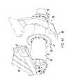
- FIG. 4Ais a lower perspective view of the arrangement of the press drum, band coulter, and trailing shank;
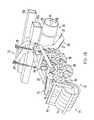
- FIG. 4Bis a perspective view of the tiller assembly
- FIG. 5Ais a perspective view of a section of the press drum and the band coulter
- FIG. 5Bis a top aerial view of the press drum assembly held by the tiller frame
- FIG. 6Ais a perspective view of one type of furrow conditioner
- FIG. 6Bis a perspective view of another type of furrow conditioner
- FIG. 7is a perspective view of the tiller assembly during tilling
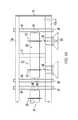
- FIG. 8is a diagrammatic view showing the spatial relationship between the press drum, band coulter, and trailing shank;
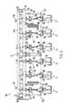
- FIG. 9is a top aerial view of another embodiment of the tiller.
- FIG. 10is a front elevational view of another embodiment of the tiller.
- FIG. 11is a perspective view of the press drum with multiple installed band coulters
- FIG. 11Ais an inset view of the end-cap support shafts supporting the ends of the press drum.
- FIG. 12is a step flow diagram of the tilling method used in association with the invention.
- FIG. 1shows a perspective view of the tiller 10 when in use in a farm field.
- the tiller 10is designed to be pulled by a tractor 11 to till multiple rows of soil 15 for planting seeds to grow various types of farm crops and vegetation (not illustrated).
- the tiller 10is designed to till either live or killed cover crops in preparation for planting of a primary crop during the growing season.
- the tiller 10is primarily a type of “strip tiller” because aside from cover crop compaction narrow strips of planting rows are tilled while leaving the surrounding compacted cover crop intact.
- a standard hitch 16allows for the connection of the tiller 10 to tractor 11 such that hydraulic control by the tractor 11 over the tiller is maintained.
- the structure of the hitch 16permits the operator of the tractor 11 to raise and lower the tiller 10 to accommodate different types of field conditions and for ease of transportation.
- the tiller 10is typically lowered fully onto the field surface and dragged behind the tractor.
- Settings on the tiller 10allow for adjustments to tilling depth pursuant to varying types of crops and field soil composition, as will be discussed.
- hitch 16is robustly connected to a support frame 12 to hydraulically control the frame.
- the support framehas two parallel beams 13 a , and 13 b , with 13 b being positioned toward the rear of the tiller 10 .
- beam 13 bmay also be referred to as a “tool bar” because a plurality of tilling “tools” typically depend rearward from the beam 13 b .
- Beams 13are connected with a series of welded lateral cross beams 17 and have their ends connected by two welded end plates 14 .
- Tiller assembles 18are connected to tool bar 13 b and trail behind it.
- Each tiller assembly 18has, in turn, a soil conditioner 71 that trails behind the assembly 18 .
- Each assemble 18also includes a pressure spring assembly 22 for biasing the tiller assembly 18 downward.
- tiller 10is supported over the soil surface 15 by two support or “gauge” wheels 19 , and a series of axially aligned press drums or rollers 31 mounted to frame 12 via angled drum support beams 46 .
- press drum, press roller, or rollershall be used interchangeably to describe a rolling cylindrical implement of predetermined length having a consistent exterior surface, as exemplified by roller 31 shown in the figures.
- the wheels 19may be adjusted by adjustable angle journal brackets 20 , as is known in the art, to adjust the height of the frame 12 over the soil surface as it moves over a planting field.
- Shank support beams 46 that support the drums 31are rotatably affixed to mounting bracket 49 and supported at their ends by beams 13 a,b .
- Each end of drum 31is mounted to the beam 46 by a journal and bearing assembly 48 , preferably using a flange type bearing.
- Press drum 31is positioned to a distance below frame 12 by gauge plate 47 such that as the tiller moves forward the majority of weight of the tiller 10 is borne by drum 31 upon the soil surface 15 .
- Tilling shank 26is positioned rearward of drum 31 and just below it in depth.
- Shank support arm 27is mounted to the rearward edge of beam 13 b in robust arrangement with shank tip 28 extending just below drum 31 as shown.
- Shank tip 28may be of any number of known types of shank tips, such as sweeps, winged tips, or ridges, to control the flow of excavated soil and debris.
- Tilling assembly 18also includes one or two pairs of wavy coulters 56 mounted to the tiller assembly frame 23 at cross members 24 .
- coulters 56are staggered in orientation to one another and may include two or four coulters in a tilling assembly 18 .
- the left three assemblies 18 of FIG. 2Ainclude four wavy coulters and two of the three right assemblies 18 include only two wavy coulters.
- the depth of each coulter 56is set by a mounting bracket holding a support post for each coulter.
- a set of rolling tires 56 amay be positioned alongside or on top of the furrow 58 to smooth the soil and compress any vegetation down further.
- the use of rolling tires 56 a in place of coulters 56may also obviate the need for additional soil conditioners trailing behind the tilling assembly, such as those described in FIGS. 6A-6B .
- FIG. 4Ashows the positional relationship between the press drum 31 , a band coulter assembly 33 , and shank 26 .
- Shank 26trails drum 31 and aligns shank tip 28 with band coulter assembly 33 .
- Shank tip 28extends below the outer circumference of band coulter assembly 33 by at least several inches so that it protrudes into the soil 15 deeper than the band coulter's cutting edge 37 .
- Journal and bearing 48 assemblysupport drum shaft 44 and drum assembly 31 on drum support beam 46 at the end of each drum assembly 31 so that the drum can rotate freely.
- FIG. 4Bshows the tiller assembly 18 arranged with four wavy coulters 56 mounted to the assembly frame 21 at parallel cross members 24 .
- Wavy coulterssmooth soil around a furrow created by shank 26 as it proceeds forward through the soil to close up any voids created by the shank 26 .
- Wavy coultersare positioned in a staggered arrangement just behind shank 26 for optimal furrow conditioning.
- FIG. 5Ashows press drum assembly 31 along its rotating axis 35 positioned vertically.
- Press drum 31includes a steel drum 32 having a hollow interior 41 , with its band coulter assembly 33 affixed to the surface 39 of drum 32 .
- Band coulter 36is mounted onto drum 32 with a pair of mounting plates 34 a,b and a series of bolts 38 .
- Coulter 36is slid over drum 32 at one end or the other, and positioned against a mounting band 40 welded onto the surface 39 .
- drum 31has a length of 72 inches, an interior diameter of 12 inches, and consists of standard 12 inch weld casing pipe having % of an inch wall thickness.
- the diameter of the band coulter 33can vary depending upon the type of crop application, but a typical diameter is 20-24 inches, with 21 inches being optimal.
- Coulter blade widthi.e. cutting depth
- press drum 31is mounted between support beams 46 on journal assemblies 48 .
- Band coulter assemblies 33are aligned with shank tip 28 to facilitate furrow clearing by shank 26 after coulter 33 cuts surface and sub-surface soil 15 , as will be discussed.
- the configuration showing in FIG. 5Bshows a relatively short roller 31 having only two coulters 33 installed on the drum surface 39 , with three rollers axial aligned between support beam 13 a and 13 b .
- the embodiment showing 10is preferred by the inventors, but various other numerical configurations of rollers and coulters are possible. For example, instead of the disclosed configuration of three rollers each holding two coulters (i.e.
- a single roller holding six coultersis possible, as will be shown below (i.e. 6 planting rows), or two rollers with four coulters (i.e. 8 planting rows), or one roller with four coulters (i.e. 4 planting rows), or a single roller with four coulters and having two fold-up rollers, one on each side with 3 coulters each (i.e. 12 planting rows).
- 6 planting rowsor two rollers with four coulters
- one roller with four coultersi.e. 4 planting rows
- a single roller with four coulters and having two fold-up rollers, one on each side with 3 coulters eachi.e. 12 planting rows.
- FIGS. 6A and 6Bshow two types of seedbed soil conditioners 71 that may be trailed behind tiller assembly 18 .
- FIG. 6Ashows a seedbed roller having a support arm 72 that is rotatably connected to the rear of tiller assembly frame 21 .
- the roller 74is typically flat-surfaced to smooth the soil as it passes underneath the roller 74 .
- FIG. 6Bshows a pair of conditioners affixed to frame 21 in the same manner, but trails instead of a pair of rotating implements.
- Frame 76holds in its forward part a soil crumbler 78 for dissipating large soil conglomerates, and a rolling basket 79 to further reduce the size of the soil particles, thereby providing a porous seedbed to facilitate water penetration and plant root proliferation.
- FIG. 7it may be seen how the tiller 10 operates in a crop field.
- roller 31moves forward as the leading edge of the tiller 10 to engage crops or crop residue.
- the tiller 10is oriented by the tractor operator with hitch 16 so that majority of the weight of tiller 10 resides on the roller 31 .
- band coulter 36slices through compressed foliage on the soil surface 15 along furrow center line 58 , and slices through any sub-surface roots or residue.
- Shank support arm 27 and tip 28clear a furrow along the furrow line 58 , thereby removing any type of crop debris and pushing up debris and soil on either side of the center line 58 .
- At least a pair of wavy coulters 56then spreads any furrow ridges or mounds created by the shank 26 adjacent to furrow center line 58 to fill in any furrow voids created by tiller shank 26 .
- a second pair of wavy coulters 58may provide further smoothing of ridges or mounds.
- shank 26is aligned with band coulter blade 36 along line 58 and, preferably, aligned with an intended furrow in the crop field.
- a pressure spring assembly 22maintains constant down-force on tiller assembly 18 to maintain continuous contact of tiller 10 on soil surface 15 and a consistence tilling depth of the shank 26 relative to the roller 31 .
- FIG. 8represents another embodiment of the tiller 10 and provides a clearer picture of the relationship between the band coulter assembly 33 , roller 31 , and tiller shank 26 .
- Shank tip 28trails behind coulter blade cutting edge 37 a distance of A 61 as coulter blade 36 cuts through ground surface 67 to a depth of F 68 .
- Drum surface 39presses against ground surface 67 as it rotates forward, thereby supporting the majority of weight of tiller 10 on the ground surface 67 .
- Shank tip 28is positioned to a depth of C 63 below the ground surface, and trails behind the press drum center rotation axis 35 a distance of B, and shank arm 27 trails behind blade edge 37 just above the ground surface a distance of D 64 . If present, wings or tip ridges may raise above tip 28 to a distance below the ground surface of E 66 .
- a 61 through F 68will vary depending upon farming location, soil conditions, and weather. For example, sandy soil conditions might require the tiller operator to raise up the shank 26 thereby decreasing the depth C 63 and move the shank 26 forward relative to the roller 32 thereby decreasing the distance A 61 behind the cutting edge 37 .
- the roller 32has a diameter of 103 ⁇ 4 inches and the band coulter disc diameter is 22 inches.
- the band coulter 36has a cutting blade depth F 68 through the ground surface 67 of approximately 5% inches.
- band coulter 36has a series of support ridges 70 formed in its surface between the mounting plates 34 and the blade edge 37 . These ridges are longitudinally oriented toward the center rolling axis of the coulter such that they provide additional support to the coulter 36 as it cuts through crop surface residue and root residue, but without inhibiting the cutting effect of the coulter blade 36 .
- Embodiment 80rearranges some elements of tiller 10 so that tiller shank 26 may be spring biased against the ground so that in the event that the shank 26 encounters a strong root or a subsurface rock, it may raise upward to surmount the obstacle without damage to the shank tip 28 nor to the arm 27 and reset to the original depth.
- Embodiment 80also presents a configuration in which a single roller is used to till multiple crop rows.
- Gauge wheels 19are relocated inside at least one tiller assembly 81 as shown to provide more interior support to tool bar 13 b .
- Four vertical pairs of support members 82rigidly connect tool bar 13 b to two smaller aligned, trailing tool bars 13 c , to which a series of soil conditioner assemblies 71 are affixed. It will also be noticed that pairs of wavy coulters 56 are attached the tool bar 13 c , thereby leaving tiller shank assembly 81 as the primary support for the shank 26 .
- a single roller 31spans the length of tool bar 13 b , having 6 coulter assemblies 33 mounted on the roller.
- the embodimentincludes front and rear stands 84 , 83 , to support the tiller 80 when detached from tractor 11 .
- single roller 31is rotatably supported by two drum support assemblies 50 , 50 ′ each having a pillow bearing assembly 86 .
- the support assemblies 50 , 50 ′serve a similar support function to the angled support arm 46 and gauge bar 47 in the configuration of the preferred embodiment 10 .
- some tractorsmight require a hydraulic lift-assist to be attached to bar 13 b in order to lift rear tool bar 13 b with its attached tiller assemblies.
- the tiller shank assemblies 81each have a pair of springs as shown to bias the shank downward to a selected depth into the soil, while allowing for shank to travel upward to pass over obstacles in the soil.
- FIG. 11shows the roller and support structure for it in the embodiment 80 .
- Roller support assembly 50includes a downwardly angled support bar 53 rotatably coupled to rear angled support member 54 via side bracket 55 , with the combination securely clamped to tool bar 13 b via clamps 51 .
- the bottom of rear angled support member 54includes a pillow bearing assembly 86 that fits over a shaft 119 that extends from the inside of roller 31 .
- a support shaft weldment 115includes a shaft 119 and two discs 117 a,b rigidly spaced from one another by four (4) gussets 118 such that disc 117 a is positioned at about the mid-point of shaft 119 .
- the weldment 115is sized such that it may be inserted into the end of the roller 31 to tightly fit the inner circumference of roller 31 , with disc 11 a welded to the inner circumference of the roller adjacent to its end, leaving a portion at the end 116 of shaft 119 extending along axis 35 outside of the roller.
- the central rotation axis 35 and the rotation axis of shaft 119must be closely aligned so that roller 31 rotates equidistantly around axis 35 as shaft 119 rotates.
- disc 117 aserves to seal the end of roller and provide a rigid support to the roller.
- the end of shaft 119may then be inserted into pillow bearing assembly 86 and repeated with assembly 50 ′ so that roller 31 is able to freely rotate below front beam 13 a and rear tool bar beam 13 b.
- each coulter 33is installed along the surface of roller 31 in the manner described above, with a spacing G 59 between each coulter arranged to match a predetermined crop row width, depending upon the crop and soil conditions of the farming field area.
- shorter tiller assemblies having rollers and coulters of varying lengthsmay be arranged as “wings” to the left and right of the configuration shown in FIGS. 9-11 to accommodate larger parallel row tilling, such as for example two (3) three row wings on each side of the (6) six coulter configuration 80 so that 12 rows may be tilled in a single pass.
- a consistent tillagemay be achieved on live cover crop or cover crop residue to achieve the benefits of planting a cover crop with a minimum of tillage labor, as may be seen in FIG. 12 .
- the tractor operatoradjusts the height of the tiller 10 (or 80) to accommodate planting field conditions 202 , and positions the tractor and tiller 10 (or 80) such that each band coulter 33 (and shank 26 ) is aligned 203 with an intended planting furrow center line 58 .
- the operatorthen lowers the tiller 10 to engage the soil surface 203 while moving forward at a 2-8 mph pace.
- the paceis determined by the density of the cover crop or crop residue that is present in the planting field, as is known in the art.
- press roller 31compresses the cover crop into a highly compressed mat 206 while slicing a 4-6 inch deep division in the surface and sub-surface soil 15 along the furrow center line 58 207 .
- the penetration of the shank and band coulter into the soilis controlled by the position of the gauge bar 47 and by adjustment of support wheels 19 via journal bracket 20 , and can vary by cover crop type, growth density, and soil type.
- Trailing soil conditioners 71may further condition the seedbed to create an optimal soil medium. Either replacing trailing soil conditioners 71 or trailing behind the soil conditioners, a planter may optionally deposit seeds into the created seedbed 210 so that an additional planting pass is obviated. After a single group of parallel planting rows is prepared, additional rows may be tilled 212 if any remain 211 until the field preparation is finished and ready for the included step of seed planting or for a separately timed planting operation.
Landscapes
- Life Sciences & Earth Sciences (AREA)
- Engineering & Computer Science (AREA)
- Mechanical Engineering (AREA)
- Soil Sciences (AREA)
- Environmental Sciences (AREA)
- Soil Working Implements (AREA)
Abstract
Description
Claims (30)
Priority Applications (1)
| Application Number | Priority Date | Filing Date | Title |
|---|---|---|---|
| US13/679,388US8887824B1 (en) | 2011-11-17 | 2012-11-16 | Tiller for residue crop preparation |
Applications Claiming Priority (2)
| Application Number | Priority Date | Filing Date | Title |
|---|---|---|---|
| US201161560806P | 2011-11-17 | 2011-11-17 | |
| US13/679,388US8887824B1 (en) | 2011-11-17 | 2012-11-16 | Tiller for residue crop preparation |
Publications (1)
| Publication Number | Publication Date |
|---|---|
| US8887824B1true US8887824B1 (en) | 2014-11-18 |
Family
ID=51870022
Family Applications (1)
| Application Number | Title | Priority Date | Filing Date |
|---|---|---|---|
| US13/679,388ActiveUS8887824B1 (en) | 2011-11-17 | 2012-11-16 | Tiller for residue crop preparation |
Country Status (1)
| Country | Link |
|---|---|
| US (1) | US8887824B1 (en) |
Cited By (14)
| Publication number | Priority date | Publication date | Assignee | Title |
|---|---|---|---|---|
| CN104737647A (en)* | 2015-04-10 | 2015-07-01 | 山东临沂烟草有限公司 | Residual mulching film recycling machine |
| US20160044857A1 (en)* | 2014-08-14 | 2016-02-18 | Deere & Company | Agricultural implement and attachment with down pressure control system |
| US20160100516A1 (en)* | 2014-10-09 | 2016-04-14 | Ben Jordan | Soil tillage apparatus and method |
| CN106954395A (en)* | 2017-03-31 | 2017-07-18 | 盐城旭华机械有限公司 | A kind of deep-ploughing rotary cultivator |
| EP3384745A1 (en)* | 2017-04-04 | 2018-10-10 | Konrad Hendlmeier | Soil cultivation device |
| US10194574B2 (en) | 2016-11-18 | 2019-02-05 | Cnh Industrial America Llc | System for adjusting smoothing tools of a harrow according to location |
| US10368474B2 (en) | 2017-01-25 | 2019-08-06 | Cnh Industrial America Llc | Double rolling basket linkage |
| US10375891B2 (en) | 2016-07-05 | 2019-08-13 | Charles H. Martin | Agricultural device |
| CN110249730A (en)* | 2019-08-02 | 2019-09-20 | 中国热带农业科学院农业机械研究所 | A sugarcane subsoiling device |
| CN110771342A (en)* | 2019-10-30 | 2020-02-11 | 华中农业大学 | Anti-winding and anti-sticking wheat strip scattering, earthing, fertilizing and seeding machine for rice stubble field |
| DE102019007772A1 (en)* | 2019-11-06 | 2021-05-06 | Mats-Frerik Blöcker | Soil cultivation device for tearing up and chopping up plants and parts of plants |
| US11266060B2 (en) | 2019-06-06 | 2022-03-08 | Cnh Industrial America Llc | System and method for controlling the operation of a seed-planting implement based on cover crop density |
| WO2022266081A3 (en)* | 2021-06-15 | 2023-03-23 | Pioneer Hi-Bred International, Inc | Agronomic practices and sustainability methods involving yield traits |
| US20240125084A1 (en)* | 2022-10-12 | 2024-04-18 | Brian Craig | Skid steer rake with variable scarifiers and clod-cleaving wheels |
Citations (30)
| Publication number | Priority date | Publication date | Assignee | Title |
|---|---|---|---|---|
| US1622968A (en) | 1926-07-27 | 1927-03-29 | Herman E Orthman | Cultivator |
| US2098738A (en) | 1937-05-19 | 1937-11-09 | Campbell George | Attachment for lister planters |
| US2221550A (en) | 1939-12-29 | 1940-11-12 | Int Harvester Co | Roll-over type dammer |
| US2269724A (en)* | 1940-05-24 | 1942-01-13 | Linkogel Albert | Grass cultivator |
| US2325997A (en) | 1941-09-17 | 1943-08-03 | Kelly | Subsoil breaker |
| US3233686A (en) | 1963-07-30 | 1966-02-08 | Taylor Machine Works | Apparatus for tilling soil |
| US3392791A (en) | 1964-10-22 | 1968-07-16 | Henry K. Orthman | Ground conditioning device |
| US3613797A (en) | 1970-04-16 | 1971-10-19 | Kelley Mfg Co | Peanut digger, shaker and inverter |
| US3766988A (en) | 1972-05-15 | 1973-10-23 | Kelley Mfg Co | Rotary hoe |
| US4102406A (en) | 1977-01-24 | 1978-07-25 | Orthman Manufacturing, Inc. | Ground conditioning device and method of conditioning soil |
| US4231433A (en) | 1978-09-11 | 1980-11-04 | Kelley Manufacturing Co. | Cultivator with tool support arm and latch for holding same in raised non-working position |
| US4298071A (en) | 1978-09-11 | 1981-11-03 | Kelley Manufacturing Co. | Cultivator with parallel quadrant plates for positioning cultivating element |
| US4453601A (en) | 1982-03-24 | 1984-06-12 | Orthman Manufacturing, Inc. | 180° Folding tool bar |
| US4492272A (en) | 1982-03-15 | 1985-01-08 | Deere & Company | Tillage implement and improved gang assembly therefor |
| US4762181A (en)* | 1987-02-03 | 1988-08-09 | Cox, Inc. | Minimum tillage implement |
| US4865132A (en)* | 1988-02-22 | 1989-09-12 | Allied Products Corporation | Tillage implement having independent depth control mechanism |
| US5062488A (en) | 1990-07-19 | 1991-11-05 | Lochmiller Alan W | Small terrace generating machine with lateral dammers |
| US5333694A (en)* | 1992-05-01 | 1994-08-02 | Roggenbuck David C | Strip-till seed bed preparation apparatus |
| US5390745A (en)* | 1992-05-07 | 1995-02-21 | Brown Manufacturing Corporation | Cultivator with sweep and sifting assemblies |
| US5623997A (en)* | 1995-08-29 | 1997-04-29 | Unverferth Manufacturing Co., Inc. | Soil zone-builder coulter closer/tiller |
| US5782309A (en) | 1994-01-25 | 1998-07-21 | Bultman; Alan D. | Apparatus and method for tilling soil |
| US6431287B1 (en) | 2000-04-05 | 2002-08-13 | Russell Ramp | Soil tiller assembly and method for tilling soil |
| US20030178209A1 (en)* | 2002-02-02 | 2003-09-25 | Dean Knobloch | Strip-till primary tillage system |
| US6681868B2 (en)* | 2002-01-28 | 2004-01-27 | Case, Llc | Rip strip primary tillage system |
| US6692351B2 (en) | 2002-07-17 | 2004-02-17 | Case Corporation | Crop residue chopper with reconfigurable fixed offset blades |
| US20040144550A1 (en)* | 2003-01-23 | 2004-07-29 | Paul Hurtis | Soil conditioning rotary reel |
| US20050016424A1 (en) | 2003-05-16 | 2005-01-27 | Ellington Kenneth J. | Crop preparation apparatus |
| US6928941B1 (en) | 2003-02-13 | 2005-08-16 | The United States Of America As Represented By The Secretary Of Agriculture | Diamond row pattern planter |
| US20070089888A1 (en) | 2005-10-26 | 2007-04-26 | Condrey Tommy H | Single pass plow |
| US7594546B2 (en)* | 2007-03-23 | 2009-09-29 | Krause Corporation | Chain reel for tillage implement |
- 2012
- 2012-11-16USUS13/679,388patent/US8887824B1/enactiveActive
Patent Citations (32)
| Publication number | Priority date | Publication date | Assignee | Title |
|---|---|---|---|---|
| US1622968A (en) | 1926-07-27 | 1927-03-29 | Herman E Orthman | Cultivator |
| US2098738A (en) | 1937-05-19 | 1937-11-09 | Campbell George | Attachment for lister planters |
| US2221550A (en) | 1939-12-29 | 1940-11-12 | Int Harvester Co | Roll-over type dammer |
| US2269724A (en)* | 1940-05-24 | 1942-01-13 | Linkogel Albert | Grass cultivator |
| US2325997A (en) | 1941-09-17 | 1943-08-03 | Kelly | Subsoil breaker |
| US3233686A (en) | 1963-07-30 | 1966-02-08 | Taylor Machine Works | Apparatus for tilling soil |
| US3392791A (en) | 1964-10-22 | 1968-07-16 | Henry K. Orthman | Ground conditioning device |
| US3613797A (en) | 1970-04-16 | 1971-10-19 | Kelley Mfg Co | Peanut digger, shaker and inverter |
| US3766988A (en) | 1972-05-15 | 1973-10-23 | Kelley Mfg Co | Rotary hoe |
| US4102406A (en) | 1977-01-24 | 1978-07-25 | Orthman Manufacturing, Inc. | Ground conditioning device and method of conditioning soil |
| US4231433A (en) | 1978-09-11 | 1980-11-04 | Kelley Manufacturing Co. | Cultivator with tool support arm and latch for holding same in raised non-working position |
| US4298071A (en) | 1978-09-11 | 1981-11-03 | Kelley Manufacturing Co. | Cultivator with parallel quadrant plates for positioning cultivating element |
| US4492272A (en) | 1982-03-15 | 1985-01-08 | Deere & Company | Tillage implement and improved gang assembly therefor |
| US4453601A (en) | 1982-03-24 | 1984-06-12 | Orthman Manufacturing, Inc. | 180° Folding tool bar |
| US4762181A (en)* | 1987-02-03 | 1988-08-09 | Cox, Inc. | Minimum tillage implement |
| US4865132A (en)* | 1988-02-22 | 1989-09-12 | Allied Products Corporation | Tillage implement having independent depth control mechanism |
| US5062488A (en) | 1990-07-19 | 1991-11-05 | Lochmiller Alan W | Small terrace generating machine with lateral dammers |
| US5333694A (en)* | 1992-05-01 | 1994-08-02 | Roggenbuck David C | Strip-till seed bed preparation apparatus |
| US5390745A (en)* | 1992-05-07 | 1995-02-21 | Brown Manufacturing Corporation | Cultivator with sweep and sifting assemblies |
| US5782309A (en) | 1994-01-25 | 1998-07-21 | Bultman; Alan D. | Apparatus and method for tilling soil |
| US5623997A (en)* | 1995-08-29 | 1997-04-29 | Unverferth Manufacturing Co., Inc. | Soil zone-builder coulter closer/tiller |
| US6431287B1 (en) | 2000-04-05 | 2002-08-13 | Russell Ramp | Soil tiller assembly and method for tilling soil |
| US6681868B2 (en)* | 2002-01-28 | 2004-01-27 | Case, Llc | Rip strip primary tillage system |
| US6761120B2 (en)* | 2002-01-28 | 2004-07-13 | Cnh America Llc | Row cleaner in combination of primary tillage shank system |
| US20030178209A1 (en)* | 2002-02-02 | 2003-09-25 | Dean Knobloch | Strip-till primary tillage system |
| US6692351B2 (en) | 2002-07-17 | 2004-02-17 | Case Corporation | Crop residue chopper with reconfigurable fixed offset blades |
| US20040144550A1 (en)* | 2003-01-23 | 2004-07-29 | Paul Hurtis | Soil conditioning rotary reel |
| US6928941B1 (en) | 2003-02-13 | 2005-08-16 | The United States Of America As Represented By The Secretary Of Agriculture | Diamond row pattern planter |
| US20050016424A1 (en) | 2003-05-16 | 2005-01-27 | Ellington Kenneth J. | Crop preparation apparatus |
| US20070089888A1 (en) | 2005-10-26 | 2007-04-26 | Condrey Tommy H | Single pass plow |
| US8235132B2 (en) | 2005-10-26 | 2012-08-07 | Mod-Track Corporation | Single pass plow |
| US7594546B2 (en)* | 2007-03-23 | 2009-09-29 | Krause Corporation | Chain reel for tillage implement |
Non-Patent Citations (10)
| Title |
|---|
| KMC Rip Strip Generation 1 Data Sheet (2 pages); publication date is unknown, but presumed to be before Nov. 17, 2011. |
| KMC Rip Strip Generation 2 Data Sheet (4 pages); publication date is unknown, but presumed to be before Nov. 17, 2011. |
| One Trip Plow Parts List KBH Corporation (Licensee of U.S. Pat. No. 8235132 to Condrey); published on May 19, 2008. |
| Orthman Data Sheet (1tRIPr) 4 pages; publication date is unknown, but presumed to be before Nov. 17, 2011. |
| Orthman Data Sheet (8315 Cultivator) 1 page; publication date is unknown, but presumed to be before Nov. 17, 2011. |
| Orthman Data Sheet (8350 Cultivator) 1 page; publication date is unknown, but presumed to be before Nov. 17, 2011. |
| Orthman Data Sheet (8375 Cultivator) 1 page; publication date is unknown, but presumed to be before Nov. 17, 2011. |
| Orthman Data Sheet (Cultivator Accessories) 1 page; publication date is unknown, but presumed to be before Nov. 17, 2011. |
| Orthman Data Sheet (Stalk Puller) 1 page; publication date is unknown, but presumed to be before Nov. 17, 2011. |
| Orthman Data Sheet (Toolbar Accessories) 2 pages; publication date is unknown, but presumed to be before Nov. 17, 2011. |
Cited By (17)
| Publication number | Priority date | Publication date | Assignee | Title |
|---|---|---|---|---|
| US20160044857A1 (en)* | 2014-08-14 | 2016-02-18 | Deere & Company | Agricultural implement and attachment with down pressure control system |
| US9723776B2 (en)* | 2014-08-14 | 2017-08-08 | Deere & Company | Agricultural implement and attachment with down pressure control system |
| US20160100516A1 (en)* | 2014-10-09 | 2016-04-14 | Ben Jordan | Soil tillage apparatus and method |
| US9723773B2 (en)* | 2014-10-09 | 2017-08-08 | Ben Jordan | Soil tillage apparatus and method |
| CN104737647A (en)* | 2015-04-10 | 2015-07-01 | 山东临沂烟草有限公司 | Residual mulching film recycling machine |
| US10375891B2 (en) | 2016-07-05 | 2019-08-13 | Charles H. Martin | Agricultural device |
| US10194574B2 (en) | 2016-11-18 | 2019-02-05 | Cnh Industrial America Llc | System for adjusting smoothing tools of a harrow according to location |
| US10368474B2 (en) | 2017-01-25 | 2019-08-06 | Cnh Industrial America Llc | Double rolling basket linkage |
| CN106954395A (en)* | 2017-03-31 | 2017-07-18 | 盐城旭华机械有限公司 | A kind of deep-ploughing rotary cultivator |
| EP3384745A1 (en)* | 2017-04-04 | 2018-10-10 | Konrad Hendlmeier | Soil cultivation device |
| US11266060B2 (en) | 2019-06-06 | 2022-03-08 | Cnh Industrial America Llc | System and method for controlling the operation of a seed-planting implement based on cover crop density |
| CN110249730A (en)* | 2019-08-02 | 2019-09-20 | 中国热带农业科学院农业机械研究所 | A sugarcane subsoiling device |
| CN110249730B (en)* | 2019-08-02 | 2024-05-31 | 中国热带农业科学院农业机械研究所 | Sugarcane field subsoiling soil preparation device |
| CN110771342A (en)* | 2019-10-30 | 2020-02-11 | 华中农业大学 | Anti-winding and anti-sticking wheat strip scattering, earthing, fertilizing and seeding machine for rice stubble field |
| DE102019007772A1 (en)* | 2019-11-06 | 2021-05-06 | Mats-Frerik Blöcker | Soil cultivation device for tearing up and chopping up plants and parts of plants |
| WO2022266081A3 (en)* | 2021-06-15 | 2023-03-23 | Pioneer Hi-Bred International, Inc | Agronomic practices and sustainability methods involving yield traits |
| US20240125084A1 (en)* | 2022-10-12 | 2024-04-18 | Brian Craig | Skid steer rake with variable scarifiers and clod-cleaving wheels |
Similar Documents
| Publication | Publication Date | Title |
|---|---|---|
| US8887824B1 (en) | Tiller for residue crop preparation | |
| US9456539B2 (en) | Apparatus and method for no-till inter-row simultaneous application of herbicide and fertilizer, soil preparation, and seeding of a cover crop in a standing crop | |
| US9445538B2 (en) | Apparatus and method for no-till inter-row simultaneous application of herbicide and fertilizer, soil preparation, and seeding of a cover crop in a standing crop | |
| US9474197B2 (en) | Universal custom agricultural field preparation implement | |
| US9320189B2 (en) | Tillage system | |
| US8627898B2 (en) | Tillage system | |
| US6431287B1 (en) | Soil tiller assembly and method for tilling soil | |
| CA2375838C (en) | Low-till harrow implement | |
| JPS6043317A (en) | Soil maintenance intercropping method and apparatus | |
| US5267517A (en) | Multi function tillage or planting implement | |
| US4524837A (en) | Soil conditioning and bed preparation apparatus | |
| Evans et al. | Development of strip tillage on sprinkler irrigated sugarbeet | |
| Friedrich | The role of no or minimum mechanical soil disturbance in Conservation Agriculture systems | |
| WO2019157312A1 (en) | Herbicide application device and method for row crop cultivation | |
| Vento et al. | Machinery for direct sowing of rice in agricultural conditions | |
| WO2018142172A1 (en) | Cultivator, especially for within-the-row cultivation | |
| RU2345513C2 (en) | Tillager | |
| CA3061314A1 (en) | Method for cultivating sown crops and apparatus for carrying out said method (variants) | |
| CN118339963A (en) | Multifunctional peanut planter and method | |
| Wightman et al. | Permanent raised bed cropping in southern Australia: practical guidelines for implementation | |
| Bachmann et al. | Conservation agriculture in Mongolia | |
| CA2854653C (en) | Universal custom agricultural field preparation implement | |
| RU198575U1 (en) | COMBINED SEEDING UNIT | |
| Dumitru et al. | Use of minimum soil tillage technology in arid areas. | |
| RU63634U1 (en) | UNIT FOR TILLING SOIL AND SEEDING |
Legal Events
| Date | Code | Title | Description |
|---|---|---|---|
| AS | Assignment | Owner name:JOHNSON, MYRON Q., ALABAMA Free format text:ASSIGNMENT OF ASSIGNORS INTEREST;ASSIGNOR:SANDERS, JOHN W, JR.;REEL/FRAME:029314/0289 Effective date:20121115 | |
| STCF | Information on status: patent grant | Free format text:PATENTED CASE | |
| FEPP | Fee payment procedure | Free format text:MAINTENANCE FEE REMINDER MAILED (ORIGINAL EVENT CODE: REM.) | |
| FEPP | Fee payment procedure | Free format text:SURCHARGE FOR LATE PAYMENT, SMALL ENTITY (ORIGINAL EVENT CODE: M2554); ENTITY STATUS OF PATENT OWNER: SMALL ENTITY | |
| MAFP | Maintenance fee payment | Free format text:PAYMENT OF MAINTENANCE FEE, 4TH YR, SMALL ENTITY (ORIGINAL EVENT CODE: M2551); ENTITY STATUS OF PATENT OWNER: SMALL ENTITY Year of fee payment:4 | |
| FEPP | Fee payment procedure | Free format text:MAINTENANCE FEE REMINDER MAILED (ORIGINAL EVENT CODE: REM.); ENTITY STATUS OF PATENT OWNER: SMALL ENTITY | |
| FEPP | Fee payment procedure | Free format text:7.5 YR SURCHARGE - LATE PMT W/IN 6 MO, SMALL ENTITY (ORIGINAL EVENT CODE: M2555); ENTITY STATUS OF PATENT OWNER: SMALL ENTITY | |
| MAFP | Maintenance fee payment | Free format text:PAYMENT OF MAINTENANCE FEE, 8TH YR, SMALL ENTITY (ORIGINAL EVENT CODE: M2552); ENTITY STATUS OF PATENT OWNER: SMALL ENTITY Year of fee payment:8 |